
www.gys.fr
Find more languages of user manuals
FR 02-09 / 58-60 DRAW ALIGNER PRO
Équerre de tirage
Pulling bracket
Richtausleger
Escuadra de tiro
Стенд для правки
Trekbalk
Braccio di tiro
EN 10-17 / 58-60
DE 18-25 / 58-60
ES 26-33 / 58-60
RU 34-41 / 58-60
NL 42-49 / 58-60
IT 50-57 / 58-60
73502 V3 08/06/2023

2
Manuel d’utilisation DRAW ALIGNER PRO
Notice originale
Merci de votre choix ! Afin de tirer le maximum de satisfaction de votre EQUERRE DE TIRAGE PRO et pour votre sécurité veuillez
lire avec attention ce mode d’emploi avant la première utilisation et de le conserver soigneusement pour toute relecture future.
AVERTISSEMENTS - RÈGLES DE SÉCURITÉ
CONSIGNE GÉNÉRALE
Ce manuel d’utilisation comprend des indications sur le fonctionnement de votre appareil et les précautions à
suivre pour votre sécurité. Merci de le lire attentivement avant la première utilisation et de le conserver soigneu-
sement pour toute relecture future. Ne pas utiliser cet outil si des pièces son manquantes ou endommagées. Ce
produit ne doit pas être modifié, de quelque manière que ce soit. Des fixations serrées à un couple excessif ou
insuffisant, susceptibles de casser, de se desserrer ou de se séparer, peuvent entraîner de graves accidents.
Les ensembles démontés peuvent devenir des projectiles. Les assemblages qui exigent un couple de serrage
spécifique doivent être vérifiés à l’aide d’un dynamomètre. Si les marquages indicateurs de la charge nominale,
de la pression de service ou des panneaux d’avertissement sont illisibles ou manquants, ils doivent être rempla-
cés. Les opérateurs et le personnel d’entretien doivent être physiquement capables de supporter la charge, le
poids et la puissance de l’équipement connecté et doivent être en mesure de réaliser le travail. L’utilisation de cet
appareil est réservée aux professionnels.
PROTECTION INDIVIDUELLE
Pour bien se protéger et protéger les autres, respecter les instructions de sécurité suivantes :
Porter des gants de protection pour limiter les risques liés à l’exposition aux vibrations. Les mouvements répétés
et l’exposition aux vibrations peuvent être nuisibles aux mains et aux bras. En cas d’engourdissement, de
démangeaison, de douleur ou de décoloration de la peau, cesser d’utiliser l’outil et consulter un médecin.
Portez une protection auditive. Une exposition prolongée au bruit de fonctionnement d’un outil pneumatique peut
entraîner une perte auditive permanente.
Porter des chaussures de sécurité afin d’éviter un accident lors d’une éventuelle chute de pièce ou du montage
ENVIRONNEMENT DE TRAVAIL
Les glissades, trébuchements ou chutes sont une cause majeure d’accidents corporels graves voire mortels. Prêter attention aux
flexibles laissés sur le sol. Utiliser toujours l’outil à une distance de sécurité par rapport aux personnes et aux objets qui se trouvent
près de la zone de travail. L’équerre de tirage Pro est prévu pour être utilisé à l’intérieur dans un environnement bien éclairé sur un
sol plat.
DESCRIPTIF DE L’EQUERRE DE TIRAGE PRO
L’Equerre de tirage Pro est destinée à être utilisée pour le redressage de tôles d’habillage. Elle permet à un opérateur de redresser
les tôles au niveau du bas de caisse mais également au niveau des ailes. Avec son mât rotatif l’équerre de tirage pro permet de
redresser les tôles suivant différents angles. La platine sous roue apport une solution pour les zones ou la prise d’appuie sous bas
de caisse n’est pas possible.

FR
3
Manuel d’utilisation DRAW ALIGNER PRO
Notice originale
MONTAGE
PROTOTYPE
Vis M12x90 : 1
Ecrou frein M12 : 1
Rondelle M12 : 2
Assembler l’articulation du
bras vertical sur la partie
horizontale de l’équerre de
la vis à l’aide la vis M12x90
et de son écrou.
Vis M12x90 : 1
Ecrou frein M12 : 1
Assembler la barre verticale
sur l’articulation du bras
vertical à l’aide la vis M12x90
et de son écrou. Placer la
goupille de réglage d’angle
pour maintenir le mat à la
verticale.

4
Manuel d’utilisation DRAW ALIGNER PRO
Notice originale
Vis M14x60 : 1
Ecrou frein M14 : 1
Rondelle M14 : 2
Accrocher le ressort et visser
le vérin sur l’articulation du
bras vertical.
Vis M12x85 : 1
Ecrou frein M12 : 1
Rondelle M12 : 2
Placer sur la partie
horizontale de l’équerre la
pièce métallique permettant
le passage de la chaine.

FR
5
Manuel d’utilisation DRAW ALIGNER PRO
Notice originale
Placer la pièce métallique
permettant le tirage sur
l’axe vertical, à l’aide de
la tige fournie.
Connecter la pompe sur
le raccord du vérin sur
l’équerre.
Ecrou frein M20 : 1
Assembler la platine sous
roue à l’aide de l’écrou M20.
Vis M10x55 : 1
Ecrou frein M10 : 1
Assembler le patin avec
le tube de Ø 25mm.

6
Manuel d’utilisation DRAW ALIGNER PRO
Notice originale
Vis M10x55 : 1
Ecrou frein M10 : 1
Assembler le carré de
fixation avec le tube de Ø
30mm.
Positionner la barre
stabilisatrice à l’arrière de
l’équerre de tirage.

FR
7
Manuel d’utilisation DRAW ALIGNER PRO
Notice originale
UTILISATION
Dans un premier temps des anneaux doivent être soudés ou coller sur la carrosserie
pour permettre le tirage avec la griffe 6 dents et la chaine. Faire passer une tige
à travers les anneaux pour permettre le tirage avec la chaine. L’équerre peut se
positionner de 2 façons contre le véhicule pour permettre le tirage :
Si le véhicule possède une lèvre sous le châssis utiliser la pièce métallique
montrée ci-contre pour s’appuyer contre la lèvre et bloquer l’équerre pendant
le tirage. Pour ce faire actionner la manivelle à l’arrière de l’équerre de tirage.
Si la zone à redresser se situe à proximité d’une roue, vous pouvez utiliser
la platine en positionnant la roue du véhicule sur la platine. La platine pivote
pour se positionner dans l’axe de tirage souhaité. Vous pouvez si besoin
rajouter un appui à l’aide des bras télescopique
L’équerre de tirage Pro dispose d’un mat rotatif permettant de modifier l’angle
de tirage afin de s’adapter à la configuration de tirage.

8
Manuel d’utilisation DRAW ALIGNER PRO
Notice originale
SECURITE LORS DE L’UTILISATION ET DU DÉPLACEMENT
Soyez attentif aux risques lors de l’utilisation de l’équerre de tirage Pro. Avant de commencer à tirer
toujours vérifier la stabilité de l’équerre de tirage Pro. Si vous utiliser les bras d’appui s’assurer qu’il soit
bien en place contre le bas de caisse ou la roue. Avec la platine sous roue, s’assurer que le véhicule
repose correctement sur cette dernière. Ne jamais se mettre derrière la chaine lorsque celle-ci est en
tension, si elle se décroche le risque de blessure est important.
Cette équerre de tirage est destinée à être utilisée pour le redressage de tôle d’habillage. Cette équerre ne doit
aucunement être utilisée sur des éléments de structure (longeron, pied milieu, renfort de bas de caisse), car ces
éléments sont constitués d’acier à haute limite élastique, très résistants, nécessitant une force de tirage très importante.
Tout dommage occasionné au produit suite à une utilisation ne suivant pas ces recommandations ne sera pas pris sous
garantie.
Ne pas positionner la pompe à la verticale au risque de la désamorcer.
Toujours placer la pompe au sol lors de son utilisation.
Ne pas se placer derrière la barre de tirage lorsqu’elle est en action. Risque de graves blessures.
MAINTENANCE
Afin que le produit puisse fonctionner dans les meilleures conditions, il est important de faire un entretien régulier selon
les instructions ci-dessous. L’intervalle de maintenance est défini en fonction d’une utilisation normale et avec une
utilisation journalière de 8h. Pour une utilisation plus intense, l’intervalle de maintenance doit être plus fréquent.
- Vérifiez l’état de la chaine et de la griffe de tirage,
- Vérifiez les pièces afin d’identifier des éventuelles fissures ou points d’usure,
- Vérifiez que les boulons sont bien serrés,
- Vérifier l’état du flexible de la pompe qu’il ne présente pas de détérioration coupure,
- Vérifier le niveau d’huile et compléter si besoin,
- Vérifier le serrage des raccords hydraulique.
ENTRETIEN
Un dépoussiérage peut être fait à l’aide d’une soufflette avant le nettoyage. Lavez l’équerre de tirage Pro avec un produit
approprié pour des surfaces d’acier peintes. Suivez les instructions indiquées sur le produit de nettoyage. Essuyez
l’équerre de tirage Pro avec un chiffon après le nettoyage. N’appliquez jamais un appareil à jet haute pression, celui-ci
peut endommager la peinture.
DÉPANNAGE
L’équerre de tirage Pro et conçu pour une utilisation effective et sécurisée à conditions que les instructions de
maintenance aient été respectées. Si vous rencontrez toutefois des problèmes de fonctionnement, voici ci-dessous
quelques conseils. Si les problèmes persistent, contactez votre réparateur ou le fabricant.
Si le bras de l’équerre Pro ne bouge pas lorsque vous actionnez la pompe manuelle :
- Vérifier que la molette de la pompe est bien serrée à fond,
- Vérifier qu’il y a suffisamment d’huile dans la pompe,
- Vérifier le bon raccordement de la pompe au vérin.
CARACTERISTIQUES TECHNIQUES
Poids du produit à vide 53 Kg
Capacité de tirage 1.2 T
Hauteur de produit 123 cm
Largeur du produit 39 cm / 116 cm
Profondeur du produit 116.5 cm / 165.6 cm
Température de stockage 0°C à 60°C
Température de fonctionnement 5°C à 50°C

FR
9
Manuel d’utilisation DRAW ALIGNER PRO
Notice originale
GARANTIE
L’équerre de tirage Pro est garantie 2 ans à partir de la date d’expédition. La garantie couvre les défauts du matériel et (ou) de
fabrication. Cette garantie est uniquement valable si l’entretien a été effectué selon les instructions indiquées dans ce manuel
d’utilisation. La garantie ne couvre pas l’entretien périodique, le calibrage ou les ajustements réguliers. Les couts de main d’œuvres
liés à ce type d’action ne sont pas couverts. Les incidents liés à une mauvaise utilisation ou une utilisation abusive risquent d’annuler
la garantie.
DEMONTAGE ET RECYCLAGE
Pour démonter l’équerre de tirage Pro, référez-vous à la rubrique (Etapes de montage) et inverser l’ordre. L’équerre de tirage Pro doit
être mise au rebut conformément aux directives actuelles relatives à l’environnement et à la mise au rebut.

10
User manual DRAW ALIGNER PRO
Translation of the original
instructions
Thank you for choosing GYS! In order to get the maximum satisfaction from your DRAW ALIGNER PRO and for your own safety,
please read these instructions carefully before using the machine for the first time and keep them for future reference..
WARNINGS - SAFETY INSTRUCTIONS
GENERAL INSTRUCTIONS
This user’s manual includes instructions on how to operate your appliance and what precautions to take for your
safety. Please read it carefully before using the device for the first time and keep it for future reference. Do not use
this machine if any parts are missing or damaged. This product must not be modified in any way. Fasteners that
are over- or under-torqued and susceptible to breakage, loosening or separation can lead to serious accidents.
Unmounted components can become projectiles. Assemblies that require a specific torque should be checked
with a torque gauge. If the markings indicating the rated load, working pressure or warning signs are illegible or
missing, they must be replaced. Users and maintenance personnel must be physically capable of supporting the
load, weight and power of the equipment when connected and must be able to carry out the work. This device is
intended for professional use only.
INDIVIDUAL PROTECTION
To protect yourself and others, please observe the following safety instructions:
Wear protective gloves to limit the risks associated with vibration exposure. Repeated movement and exposure to
vibrations can be harmful to both the hands and arms. In the event of numbness, itching, pain or discolouration of
the skin, stop using the tool and consult a doctor.
Wear ear protection. Prolonged exposure to the noise of a pneumatic tool can lead to permanent hearing loss.
Wear safety shoes to avoid accidents in the event that parts fall or when assembling the machine.
WORK ENVIRONMENT
Slips, trips or falls are a major cause of serious injury or death. Pay attention to loose hoses on the floor. Always use the tool at a
safe distance from people and objects around the work area. The DRAW ALIGNER PRO is intended for indoor use only in a well-lit
environment on a flat surface.
DESCRIPTION OF THE DRAW ALIGNER PRO
The DRAW ALIGNER PRO is intended to be used for straightening cladding plates. It allows the operator to straighten the sheet metal
not only at the bodywork level but also at the flange level. With its rotating pole, the DRAW ALIGNER PRO can be used to straighten
sheet metal at various angles. The under-wheel support plate provides solutions for areas where underbody support is not possible.

EN
11
User manual DRAW ALIGNER PRO
Translation of the original
instructions
ASSEMBLY
PROTOTYPE
M12x90 screw: 1
M12 lock nut: 1
M12 washer: 2
Assemble the vertical arm
joint to the horizontal part
of the screw bracket using
the M12x90 screw and its
corresponding nut.
M12x90 screw: 1
M12 lock nut: 1
Connect the vertical bar
to the vertical arm joint
using the M12x90 screw
and nut. Position the angle
adjument pin to keep the
pole vertical.

12
User manual DRAW ALIGNER PRO
Translation of the original
instructions
M14x60 screw: 1
M14 lock nut: 1
M14 washer: 2
Attach the spring and screw
the cylinder in position to the
vertical arm joint.
M12x85 screw: 1
M12 lock nut: 1
M12 washer: 2
Attach the metal part
allowing the chain to pass
through on to the horizontal
part of the bracket.

EN
13
User manual DRAW ALIGNER PRO
Translation of the original
instructions
Place the metal, pulling
part on the vertical pole,
using the rod provided.
Connect the pump to
the bracket’s cylinder
connection.
M20 lock nut: 1
Attach the under-wheel plate
using the M20 nut.
M10x55 screw: 1
M10 lock nut: 1
Assemble the slider with
the Ø 25mm tube.

14
User manual DRAW ALIGNER PRO
Translation of the original
instructions
M10x55 screw: 1
M10 lock nut: 1
Assemble the square
bracket with the Ø 30 mm
tube.
Position the stabiliser bar
behind the pulling bracket.

EN
15
User manual DRAW ALIGNER PRO
Translation of the original
instructions
APPLICATION
Firstly, rings must be welded or glued to the bodywork to allow the double claw foot
chain to be attached. Pass a rod through the rings to allow the chain to be pulled
through. The bracket can be positioned in two different ways on the vehicle to allow
for easy pulling:
If the vehicle has a lip under the chassis, use the metal piece shown opposite
to rest against the lip and lock the bracket in place during pulling. To do this,
turn the crank on the back of the drawer aligner.
If the area to be straightened is near a wheel, you can use the plate by
positioning the vehicle’s wheel on the plate. The plate swivels to position itself
in the desired pull direction. If necessary, you can add a support using the
telescopic extensions.
The DRAW ALIGNER PRO has a rotating pole to change the pull angle to suit
the pulling situation.

16
User manual DRAW ALIGNER PRO
Translation of the original
instructions
SAFETY WHEN USING AND MOVING
Be aware of the risks when using the DRAW ALIGNER PRO. Before beginning to pull, always check the stability
of the DRAW ALIGNER PRO. If you are using the support arms, make sure they are firmly in place against the
underbody or wheel. With the plate under the wheel, ensure that the vehicle rests correctly on the plate. Never
stand behind the chain when it is under tension. If it comes off, there is a high risk of injury.
This drawing bracket is intended to be used for straightening cladding plates. This bracket must not be used on structural components
(sleeper blocks, B pillars, lower-body reinforcements), as these elements are made of high-strength, high-tensile steel and require a
very high pulling force. Any damage to the product resulting from use that does not follow these recommendations will not be covered
by the warranty.
Do not position the pump vertically as this may cause the pump to be deflated.
Always place the pump on the ground when in use.
Do not stand behind the drawbar when it is in operation. Risk of serious injury.
MAINTENANCE
In order for the product to work at its best, it is important to perform regular maintenance according to the instructions below. The
frequently that maintenance is carried out is based on normal use and a daily usage of eight hours. For more intensive use, the
maintenance should be carried out more frequently.
- Check the condition of the chain and the pulling claw,
- Check the parts for possible cracks or wear,
- Check that the bolts are tight,
- Check the pump hose for damage,
- Check the oil level and top up if necessary,
- Check the tightness of the hydraulic connections.
MAINTENANCE
Dusting can be done with an air gun before cleaning. Wash the DRAW ALIGNER PRO with a product suitable for painted, steel
surfaces. Follow the cleaning product’s instructions. After cleaning, wipe the DRAW ALIGNER PRO with a cloth. Never use a high-
pressure sprayer as this can damage the paint.
TROUBLESHOOTING
Providing that the maintenance instructions have been followed, the DRAW ALIGNER PRO is designed for safe and effective
useage. However, if you do encounter any operating problems, here is some advice. If problems persist, contact the repairer or the
manufacturer.
If the DRAW ALIGNER PRO’s arm does not move when you operate the hand pump:
- Check that the pump’s control knob is fully tightened,
- Check that there is enough oil in the pump,
- Check that the pump is correctly connected to the jack cylinder.
TECHNICAL FEATURES
Product weight when empty 53 kg
Pulling capacity 1.2 T
Height of product 123 cm
Width of product 39 cm / 116 cm
Depth of product 116.5 cm / 165.6 cm
Storage temperature 0°C to 60°C
Operating temperature 5°C to 50°C

EN
17
User manual DRAW ALIGNER PRO
Translation of the original
instructions
WARRANTY
The DRAW ALIGNER PRO is covered by a two-year warranty from the date of shipment. The warranty covers defects in equipment
and/or workmanship. This warranty is only valid if the maintenance has been carried out according to the instructions in this user
manual. The warranty does not cover periodic maintenance, calibration or regular adjustments. Labour costs related to this type of
operation are not covered. Incidents related to misuse or abuse may void the warranty.
DISMANTLING AND RECYCLING
To dismantle the DRAW ALIGNER PRO, refer to the section (Assembly steps) and reverse the order. The DRAW ALIGNER PRO
must be disposed of in accordance with current environmental and disposal guidelines.

18
Betriebsanleitung DRAW ALIGNER PRO
Übersetzung der
Originalbetriebsanleitung
Danke, dass Sie sich für uns entschieden haben.
Danke für Ihre Wahl!
Damit Ihr RICHTAUSLEGER PRO Ihnen noch viele Jahre gute Dienste leistet und zu Ihrer eigenen Sicherheit, lesen Sie bitte dieses
Handbuch vor der ersten Benutzung sorgfältig durch und bewahren Sie es zum späteren Nachschlagen auf.
WARNUNGEN - SICHERHEITSREGELN
ALLGEMEINER HINWEIS
Diese Benutzerhandbuch enthält Informationen zur Bedienung des Geräts und zu Vorsichtsmaßnahmen für Ihre
Sicherheit. Bitte lesen Sie diese vor dem ersten Gebrauch sorgfältig durch und bewahren Sie sie zum späteren
Nachschlagen auf. Verwenden Sie dieses Gerät nicht, wenn Teile fehlen oder sie beschädigt sind. Dieses Gerät
darf in keiner Weise modifiziert werden. Zu fest oder zu wenig angezogene Befestigungselemente, die anfällig
für Bruch, Lockerung oder Loslösung sind, können zu schweren Unfällen führen. Abgebrochene Teile können
zu Geschossen werden. Verbindungen, die ein bestimmtes Drehmoment erfordern, müssen mit einem Dyna-
mometer überprüft werden. Wenn die Aufschriften für die Nennlast, den Betriebsdruck oder die Warnzeichen
unleserlich sind oder fehlen, müssen sie ersetzt werden. Bediener und Wartungspersonal müssen der Last, dem
Gewicht und der Leistung der angeschlossenen Geräte körperlich standhalten und die Arbeit ausführen können.
Die Nutzung dieses Geräts ist Fachkräften vorbehalten.
INDIVIDUELLER SCHUTZ
Schützen Sie daher sich selbst und andere. Beachten Sie unbedingt die folgenden Sicherheitshinweise:
Tragen Sie Schutzhandschuhe, um die Risiken, die mit Schwingungsbelastungen verbunden sind, zu begrenzen.
Die wiederholten Bewegungen und die Schwingungsbelastung können für Hände und Arme schädlich sein. Bei
Taubheit, Juckreiz, Schmerzen oder Verfärbungen der Haut verwenden Sie das Gerät nicht weiter und suchen
einen Arzt auf.
Tragen Sie einen Gehörschutz. Längere Lärmbelastung von einem Druckluftwerkzeug kann zu dauerhaftem
Hörverlust führen.
Tragen Sie Sicherheitsschuhe, um Unfälle beim möglichen Herabfallen von Teilen oder bei der Montage zu
vermeiden.
ARBEITSUMGEBUNG
Ausrutschen, Stolpern und Stürze gehören zu den Hauptursachen für schwere oder tödliche Unfälle. Achten Sie auf am Boden
liegende Schläuche. Bedienen Sie das Werkzeug immer mit einem sicheren Abstand zu Personen und Gegenständen, die sich in
der Nähe des Arbeitsbereichs befinden. Der Richtausleger Pro ist zur Verwendung in Innenräumen und in einer gut beleuchteten
Umgebung auf ebenem Boden vorgesehen.
BESCHREIBUNG DES RICHTAUSLEGERS PRO
Der Richtausleger Pro soll Außenhautbleche richten. Der Bediener kann damit die Bleche im Bereich des Schwellers und auch
im Bereich der Kotflügel richten. Mit seinem Auslegearm kann der Richtausleger Pro zum Richten von Blechen in verschiedenen
Winkeln eingesetzt werden. Die Platte unter dem Rad bietet eine Lösung für die Bereiche, in denen das Abstützen unter dem
Schweller nicht möglich ist.

DE
19
Betriebsanleitung DRAW ALIGNER PRO
Übersetzung der
Originalbetriebsanleitung
MONTAGE
PROTOTYPE
Schraube M12x90 : 1
Selbsichernde
Schraubenmutter M12 : 1
Unterlegscheibe M12 : 2
Befeigen Sie das Gelenk
des vertikalen Arms mit
der Schraube M12x90 und
ihrer Schraubenmutter
am horizontalen Teil des
Schraubwinkels.
Schraube M12x90 : 1
Selbsichernde
Schraubenmutter M12 : 1
Befeigen Sie den
Vertikalbalken am Gelenk
des vertikalen Arms mit
der Schraube M12x90 und
ihrer Schraubenmutter.
Setzen Sie den Stift für
die Winkeleinellung ein,
um den Ma senkrecht zu
halten.

20
Betriebsanleitung DRAW ALIGNER PRO
Übersetzung der
Originalbetriebsanleitung
Schraube M14x60 : 1
Selbstsichernde
Schraubenmutter M14 : 1
Unterlegscheibe M14 : 2
Hängen Sie die Feder ein
und schrauben Sie den
Zylinder auf das Gelenk des
vertikalen Arms.
Schraube M12x85 : 1
Selbstsichernde
Schraubenmutter M12 : 1
Unterlegscheibe M12 : 2
Platzieren Sie auf
dem horizontalen Teil
des Winkeleisens das
Metallstück, durch das die
Kette läuft.

DE
21
Betriebsanleitung DRAW ALIGNER PRO
Übersetzung der
Originalbetriebsanleitung
Platzieren Sie das
Metallstück, das das
Ziehen auf der vertikalen
Achse ermöglicht, mit
dem mitgelieferten
Bolzen.
Schließen Sie die
Pumpe am Zylinder am
Winkeleisen an.
Selbstsichernde
Schraubenmutter M20 : 1
Befestigen Sie mit der
Schraubenmutter M20 die
Platte unter dem Rad.
Schraube M10x55 : 1
Selbstsichernde
Schraubenmutter M10 : 1
Verbinden Sie das
Gleitstück mit dem Ø 25
mm-Rohr.

22
Betriebsanleitung DRAW ALIGNER PRO
Übersetzung der
Originalbetriebsanleitung
Schraube M10x55 : 1
Selbstsichernde
Schraubenmutter M10 : 1
Verbinden Sie das
Befestigungsviereck mit
dem Ø 30 mm-Rohr.
Platzieren Sie den
Stabilisator hinten am
Richtausleger.

DE
23
Betriebsanleitung DRAW ALIGNER PRO
Übersetzung der
Originalbetriebsanleitung
VERWENDUNG
Zunächst müssen Ringe an die Karosserie geschweißt oder geklebt werden, um das
Ziehen mit der 6-Haken-Kralle und der Kette zu ermöglichen. Führen Sie eine Stange
durch die Ringe, damit die Kette gezogen werden kann. Der Ausleger kann auf 2 Arten
gegen das Fahrzeug gestellt werden, damit gezogen werden kann:
Wenn das Fahrzeug eine Auflagefläche unter dem Fahrgestell hat, verwenden
Sie das nebenstehend abgebildete Metallstück, um sich dort abzustützen und
den Ausleger während des Ziehens zu blockieren. Betätigen Sie dazu das
Drehrad hinten am Richtausleger.
Wenn sich der zu richtende Bereich in der Nähe eines Rades befindet,
können Sie die mitgelieferte Platte verwenden und das Fahrzeugrad auf die
Platte stellen. Die Platte dreht sich, um sich auf der gewünschten Ziehachse
zu positionieren. Sie können ggf. mit Teleskoparmen eine Stütze hinzufügen.
Der Richtausleger Pro verfügt über einen Zugbalken, um den Zugwinkel
entsprechend der Zugkonfiguration zu ändern.

24
Betriebsanleitung DRAW ALIGNER PRO
Übersetzung der
Originalbetriebsanleitung
SICHERHEITSHINWEISEVERWENDUNG UNDLAGERUNG
Passen Sie beim Einsatz des Richtauslegers Pro auf Gefahren auf. Überprüfen Sie immer die Stabilität des
Richtauslegers Pro, bevor Sie ihn in Betrieb nehmen. Wenn Sie die Traverse einsetzen, sorgen Sie dafür, dass sie
am Schweller oder am Rad anliegen. Bei der Platte unter dem Rad stellen Sie sicher, dass das Fahrzeug richtig
darauf steht. Stellen Sie sich niemals hinter die Kette, wenn diese unter Spannung steht, denn wenn sie sich löst,
ist die Verletzungsgefahr groß.
Dieser Richtausleger ist zum Richten und Instandsetzen von Außenhautblechen vorgesehen. Dieser Richtausleger darf nicht an
Strukturelementen (Längsträger, Mittelfuß, Schwellerverstärkung) verwendet werden, da diese Elemente aus hochfestem Stahl
gefertigt sind und eine sehr hohe Zugkraft erfordern. Produktschäden aufgrund nicht bestimmungsgemäßer oder unsachgemäßer
Verwendung fallen nicht unter die Garantie.
Positionieren Sie die Pumpe nicht senkrecht, da sonst die Gefahr besteht, dass sie entschärft wird.
Stellen Sie die Pumpe immer auf den Boden, wenn Sie sie benutzen.
Stellen Sie sich nicht hinter die Deichsel, wenn diese in Betrieb ist. Gefahr von schweren Verletzungen.
WARTUNG
Damit das Produkt unter den besten Bedingungen funktioniert, muss gemäß der folgenden Anleitung eine regelmäßige Wartung
durchgeführt werden. Das Wartungsintervall ist nach normalem Einsatz und bei einer täglichen Nutzung von 8 Stunden definiert.Bei
einer häufigeren Nutzung muss die Wartung öfter erfolgen.
- Überprüfen Sie den Zustand der Kette und der Zugkralle,
- Überprüfen Sie die Teile auf mögliche Risse oder etwaigen Verschleiß,
- Überprüfen Sie, ob die Schrauben fest angezogen sind,
- Überprüfen Sie den Pumpenschlauch auf Beschädigungen,
- Überprüfen Sie den Ölstand und füllen Sie diesen ggf. auf,
- Überprüfen Sie die Befestigung der Hydraulikanschlüsse.
PFLEGE
Vor der Reinigung kann mit einem Druckluftreiniger abgestaubt werden. Waschen Sie den Richtausleger Pro mit einem Produkt,
das für lackierte Stahloberflächen geeignet ist. Befolgen Sie die Anweisungen, die auf dem Reinigungsprodukt stehen. Wischen Sie
den Richtausleger Pro nach der Reinigung mit einem Tuch ab. Verwenden Sie nie ein Hochdruckstrahlgerät, der Lack kann sonst
beschädigt werden.
FEHLERBEHEBUNG
Der Richtausleger Pro ist für eine effektive und sichere Verwendung ausgelegt, sofern die Wartungsanleitung befolgt wird. Sie finden
nachfolgend einige Tipps, falls Sie doch auf Funktionsprobleme stoßen. Wenn die Probleme weiterhin bestehen, wenden Sie sich an
Ihren Techniker oder an den Hersteller.
Wenn sich der Arm des Richtausleger Pro nicht bewegt, wenn Sie die Handpumpe betätigen:
- Überprüfen Sie, ob das Pumpenrad vollständig angezogen ist,
- Überprüfen Sie, ob sich genügend Öl in der Pumpe befindet,
- Überprüfen Sie, ob die Pumpe richtig am Zylinder angeschlossen ist.
TECHNISCHE EIGENSCHAFTEN
Gewicht des reinenGeräts 53 Kg
Zugleistung 1.2 T
Gerätehöhe 123 cm
Gerätebreite 39 cm / 116 cm
Gerätetiefe 116.5 cm / 165.6 cm
Lagertemperatur 0°C à 60°C
Betriebstemperatur 5°C à 50°C

DE
25
Betriebsanleitung DRAW ALIGNER PRO
Übersetzung der
Originalbetriebsanleitung
GARANTIE
Der Richtausleger Pro hat ab dem Versanddatum 2 Jahre Garantie. Die Garantie deckt Material- und/oder Verarbeitungsfehler ab.
Diese Garantie gilt nur, wenn die Wartung gemäß den Anweisungen in diesem Benutzerhandbuch durchgeführt wurde. Die Garantie
erstreckt sich nicht auf regelmäßige Wartung, Kalibrierung oder regelmäßige Justierungen.Arbeitskosten im Zusammenhang mit
dieser Art von Arbeiten sind nicht abgedeckt. Durch unsachgemäßen Gebrauch oder übermäßigen Einsatz kann die Garantie
erlöschen.
DEMONTAGE UND RECYCLING
Zur Demontage des Richtauslegers Pro lesen Sie den Abschnitt (Montageschritte) und gehen in umgekehrter Reihenfolge vor. Der
Richtausleger Pro muss nach den geltenden Umwelt- und Entsorgungsrichtlinien entsorgt werden.

26
Manual de uso DRAW ALIGNER PRO
Traducción de las instrucciones
originales
¡Gracias por su elección! Para obtener la máxima satisfacción de su ESCUADRA DE TIRO PRO y por su propia seguridad, lea aten-
tamente estas instrucciones antes de utilizarla por primera vez y guárdelas para futuras consultas.
ADVERTENCIAS - NORMAS DE SEGURIDAD
CONSIGNA GENERAL
Este manual de uso contiene indicaciones sobre el funcionamiento de su aparato y las precauciones que debe
tomar para su seguridad. Léalo atentamente antes del primer uso y consérvelo con cuidado para cualquier relec-
tura en el futuro. No utilice esta herramienta si falta alguna pieza o está dañada. Este producto no debe ser mo-
dificado de ninguna manera. Los sujetadores que se aprietan con un par de apriete excesivo o insuficiente, que
pueden romperse, aflojarse o separarse, pueden causar accidentes graves. Los conjuntos desmontados pueden
convertirse en proyectiles. Los montajes que requieren un par de apriete específico deben ser comprobados
con un torquímetro. Si las marcas que indican la carga nominal, la presión de trabajo o los signosLas etiquetas
de advertencia son ilegibles o faltan, deben ser reemplazadas. Los operadores y el personal de mantenimiento
deben ser físicamente capaces de soportarla carga, el peso y la potencia del equipo conectado y debe ser capaz
de realizar el trabajo. Este dispositivo está diseñado para uso profesional solamente.
PROTECCION INDIVIDUAL
Para protegerse correctamente y proteger a los demás, siga las instrucciones de seguridad siguientes:
Use guantes protectores para limitar los riesgos asociados con la exposición a la vibración. El movimiento
repetido y la exposición a la vibración pueden ser perjudiciales para las manos y los brazos. Si se produce
entumecimiento, comezón, dolor o decoloración de la piel, interrumpa el uso y consulte a un médico.
Use protección para los oídos. Exposición prolongada al ruido de funcionamientode una herramienta neumática
puede resultar en una pérdida auditiva permanente.
Lleve zapatos de seguridad para evitar accidentes en caso de caída de piezas o durante el montaje.
ENTORNO DE TRABAJO
Los resbalones, tropiezos o caídas son una causa importante de lesiones graves o muerte. Preste atención a las mangueras dejadas
en el suelo. Utilice la herramienta siempre a una distancia segura de las personas y objetos que se encuentren en las proximidades
del área de trabajo. Le Escuadra de tiro Pro está pensada para su uso en interiores, en un entorno bien iluminado y sobre un suelo
plano.
DESCRIPCIÓN DE LA ESCUADRA DE TIRO PRO
La escuadra de tiro Pro está diseñada para ser utilizada para enderezar hojas de corte. Permite al operario enderezar las chapas en
los bajos y también en las alas. Con su mástil giratorio, puede utilizarse para enderezar chapas en diferentes ángulos. La placa bajo
la rueda ofrece una solución para las zonas en las que no es posible el apoyo de los bajos.

ES
27
Manual de uso DRAW ALIGNER PRO
Traducción de las instrucciones
originales
MONTAJE
PROTOTYPE
Tornillo M12x90 : 1
Tuerca freno M12: 1
Arandela M12: 2
Montar la articulación del
brazo vertical a la parte
horizontal del soporte de
tornillo utilizando el tornillo
M12x90 y su tuerca.
Tornillo M12x90 : 1
Tuerca freno M12: 1
Monte la barra vertical en la
articulación del brazo vertical
utilizando el tornillo M12x90
y su tuerca. Coloque el
pasador de ajue del ángulo
para mantener el máil
vertical.

28
Manual de uso DRAW ALIGNER PRO
Traducción de las instrucciones
originales
Tornillo M14x60 : 1
Tuerca freno M14: 1
Arandela M14: 2
Coloque el muelle y atornille
el cilindro a la articulación
del brazo vertical.
Tornillo M12x85 : 1
Tuerca freno M12: 1
Arandela M12: 2
Coloque la parte metálica
para la cadena en la parte
horizontal del soporte.

ES
29
Manual de uso DRAW ALIGNER PRO
Traducción de las instrucciones
originales
Coloque la pieza metálica
que permite el arrastre en
el eje vertical, utilizando
la varilla suministrada.
Conecte la bomba a la
conexión del cilindro en el
soporte.
Tuerca freno M20: 1
Montar la placa bajo la rueda
con la tuerca M20.
Tornillo M10x55 : 1
Tuerca freno M10: 1
Montar el patín con el
tubo de Ø 25mm.

30
Manual de uso DRAW ALIGNER PRO
Traducción de las instrucciones
originales
Tornillo M10x55 : 1
Tuerca freno M10: 1
Montar el cuadrado de
fijación con el tubo de Ø
30mm.
Coloque la barra
estabilizadora en la parte
trasera del soporte de
tracción.

ES
31
Manual de uso DRAW ALIGNER PRO
Traducción de las instrucciones
originales
UTILIZACIÓN
En primer lugar, hay que soldar o pegar los anillos al cuerpo para poder tirar de la
garra de 6 dientes y de la cadena. Pase una varilla a través de las anillas para poder
tirar con la cadena. La Escuadra puede colocarse de 2 maneras contra el vehículo
para permitir el tirón:
Si el vehículo tiene un labio debajo del chasis, utilice la pieza metálica que
se muestra al lado para apoyarse en el labio y bloquear el soporte durante el
tirón. Para ello, accione la manivela situada en la parte posterior del soporte
de tracción.
Si la zona a enderezar está cerca de una rueda, puede utilizar la placa
colocando la rueda del vehículo sobre la misma. La rueda se puede girar
al eje de tracción deseado. Si es necesario, puede añadir soporte con los
brazos telescópicos.
La escuadra de tiro Pro tiene un mástil giratorio que permite cambiar el ángulo
de tiro para adaptarse a la configuración de tiro.

32
Manual de uso DRAW ALIGNER PRO
Traducción de las instrucciones
originales
SEGURIDAD EN EL USO Y EN LOS DESPLAZAMIENTOS
Sea consciente de los riesgos al utilizar la escuadra de tiro Pro. Antes de empezar a tirar, compruebe siempre la
estabilidad de la escuadra Si utiliza los brazos de soporte, asegúrese de que estén firmemente colocados contra
los bajos de la carrocería o la rueda. Cuando utilice la placa bajo la rueda, asegúrese de que el vehículo está
apoyado correctamente sobre la rueda. No se coloque nunca detrás de la cadena cuando esté en tensión, si se
despliega el riesgo de lesiones es alto.
La escuadra de tiro Pro está diseñada para ser utilizada para enderezar hojas de corte. Esta escuadra no debe utilizarse en
elementos estructurales (largueros, pilar central, refuerzo de los bajos de la carrocería), ya que estos elementos son de acero de alta
resistencia y requieren una fuerza de tracción muy elevada. Cualquier daño causado al producto como resultado de un uso que no
siga estas recomendaciones no estará cubierto por la garantía.
No coloque la bomba en posición vertical, ya que podría desinflarse.
Coloque siempre la bomba en el suelo cuando la utilice.
No se sitúe detrás de la barra de tiro cuando esté en funcionamiento. Riesgo de lesiones graves.
MANTENIMIENTO
Para que el producto funcione en las mejores condiciones, es importante realizar un mantenimiento periódico según las instrucciones
que se indican a continuación. El intervalo de mantenimiento se basa en un uso normal y una utilización diaria de 8 horas. Para un
uso más intensivo, el intervalo de mantenimiento debe ser más frecuente.
- Compruebe el estado de la cadena y de la garra de tracción,
- Revise las piezas en busca de grietas o puntos de desgaste.
- Comprueba que los pernos y tornillos estén bien apretados.
- Compruebe el estado de la manguera de la bomba en busca de daños o cortes,
- Compruebe el nivel de aceite y rellene si es necesario,
- Compruebe la estanqueidad de las conexiones hidráulicas.
MANTENIMIENTO
El polvo puede ser removido con un soplador antes de limpiarlo. Lave la escuadra con un producto adecuado para superficies de
acero pintadas. Siga las instrucciones del producto de limpieza. Limpie la escuadra con un paño después de la limpieza. Nunca
aplique un pulverizador de alta presión, puede dañar la pintura.
SOLUCIÓN DE PROBLEMAS
La escuadra de tiro Pro está diseñado para un uso seguro y eficaz siempre que se hayan seguido las instrucciones de mantenimiento.
El soporte de la llave de impacto está diseñado para un uso eficaz y seguro, siempre que se hayan seguido las instrucciones de
mantenimiento. Si los problemas persisten, póngase en contacto con su taller de reparación o con el fabricante.
Si el brazo de la escuadra no se mueve al accionar la bomba manual:
- Compruebe que el pomo de la bomba está completamente apretado,
- Compruebe que hay suficiente aceite en la bomba,
- Compruebe que la bomba está bien conectada al cilindro.
CARACTERÍSTICAS TÉCNICAS
Peso del producto en vacío 53 Kg
Capacidad de tracción 1.2 T
Altura del producto 123 cm
Anchura del producto 39 cm – 116 cm
Profundidad del producto 116.5 cm – 165.6 cm
Temperatura de almacenaje 0°C a 60°C
Temperatura de funcionamiento 5°C a 50°C

ES
33
Manual de uso DRAW ALIGNER PRO
Traducción de las instrucciones
originales
GARANTÍA
La escuadra de tiro Pro tiene una garantía de 2 años a partir de la fecha de envío. La garantía cubre los defectos de materiales y/o
mano de obra. Esta garantía sólo es válida si el mantenimiento se ha llevado a cabo de acuerdo con las instrucciones de este manual
de usuario. La garantía no cubre el mantenimiento periódico, la calibración o los ajustes regulares. Los gastos de mano de obra
relacionados con este tipo de acción no están cubiertos. Los incidentes de mal uso o abuso pueden anular la garantía.
DESMONTAJE Y RECICLAJE
Para desmontar la escuadra, consulte (Pasos de montaje) e invierta el orden.. La escuadra debe eliminarse de acuerdo con las
directrices medioambientales y de eliminación vigentes.

34
Инструкция по
применению DRAW ALIGNER PRO
Перевод оригинальных
инструкций
Благодарим за ваш выбор! Чтобы получить максимально использовать возможности PRO SHOOTING SET а также для вашей
безопасности, пожалуйста, внимательно прочитайте данное руководство перед первым использованием и сохраните его для
дальнейшего использования.
ПРЕДОСТЕРЕЖЕНИЯ - ПРАВИЛА БЕЗОПАСНОСТИ
ОБЩИЕ УКАЗАНИЯ
Данная инструкция описывает функционирование вашего устройства и меры предосторожности в целях
обеспечения вашей безопасности. Пожалуйста, прочтите ее перед первым использованием и сохраните,
чтобы при надобности перечитать. Не используйте этот инструмент, если какие-либо детали отсутствуют
или повреждены. Запрещается каким-либо образом модифицировать данное изделие. Крепеж который
затянут с избыточной или недостаточной силой может быть поврежден и привести к серьезным авариям.
Не закрепленные детали, могут вылететь при работе. Соединения, требующие определенного момента
затяжки, следует проверять динамометрическим ключом. Если маркировка, указывающая номинальную
нагрузку, рабочее давление или предупреждающие знаки, неразборчива или отсутствует, ее необходимо
заменить. Операторы и обслуживающий персонал должны быть физически готовы к нагрузке и мощности
оборудования и должны быть в состоянии выполнять работу на этом аппарате. Использование этого
устройства предназначено только для профессионалов.
ИНДИВИДУАЛЬНАЯ ЗАЩИТА
Что бы правильно защитить себя и окружающих, соблюдайте следующие правила безопасности:
Надевайте защитные перчатки, чтобы ограничить риски, связанные с воздействием вибрации.
Повторяющиеся движения и воздействия вибрации могут быть вредны для рук и кистей. При появлении
онемения, зуда, боли или изменения цвета кожи прекратите использование и обратитесь к врачу.
Носите защиту для ушей. Длительное воздействие шума от пневматического инструмента может привести
к необратимой потере слуха.
Носите защитную обувь, чтобы избежать несчастных случаев при падении деталей или во время сборки.
РАБОЧАЯ СРЕДА
Скольжение, спотыкание и падение - основная причина серьезных несчастных случаев и также несчастных случаев со
смертельным исходом. Обращайте внимание на провода, оставленные на полу. Всегда используйте инструмент, находясь
на безопасном расстоянии от людей и предметов, находящихся в рабочей зоне. Стапель угловой Pro предназначен для
использования внутри помещений в хорошо освещенном месте на ровной поверхности.
ОПИСАНИЯ УГЛОВОГО СТАПЕЛЯ
Стапель угловой Pro предназначен для выпрямления облицовочных листов. Он позволяет оператору выпрямлять листы
на уровне днища, а также на уровне крыльев. Благодаря вращающейся мачте профессиональный угловой стапель можно
использовать для выпрямления листов под разными углами. Пластина под колесо обеспечивает решение для тех областей,
где опора под колесо невозможна.

RU
35
Инструкция по
применению DRAW ALIGNER PRO
Перевод оригинальных
инструкций
СБОРКА
PROTOTYPE
Винт M12x90 1
Стопорная гайка M12: 1
Шайба М12: 2
Соберите шарнир
вертикального плеча на
горизонтальной части
углового стапеля с
помощью винта M12x90 и
его гайки.
Винт M12x90 1
Стопорная гайка M12: 1
Соберите шарнир
вертикального плеча на
вертикальной части с
помощью винта M12x90
и его гайки. Установите
штифт регулировки угла
наклона, чтобы мачта
оставалось вертикальной.

36
Инструкция по
применению DRAW ALIGNER PRO
Перевод оригинальных
инструкций
Винт M14x60 1
Стопорная гайка M14: 1
Шайба М14: 2
Прикрепите пружину и
прикрутите цилиндр к
шарниру вертикального
рычага.
Винт M12x85 1
Стопорная гайка M12: 1
Шайба М12: 2
Поместите на
горизонтальную часть
стапеля металлическую
деталь, через которую
будет проходить цепь.

RU
37
Инструкция по
применению DRAW ALIGNER PRO
Перевод оригинальных
инструкций
Установите
металлическую деталь
на вертикальную ось,
используя прилагаемый
стержень.
Подсоедините насос к
разъему цилиндра на
стапеле.
Стопорная гайка M20: 1
Установите пластину под
колесо с помощью гайки
М20.
Винт M10x55 1
Стопорная гайка M10: 1
Установите подошвы
с помощь трубки Ø
25mm.
Винт M10x55 1

38
Инструкция по
применению DRAW ALIGNER PRO
Перевод оригинальных
инструкций
Стопорная гайка M10: 1
Установите квадратный
держатель при помощи
трубки Ø 30mm.
Расположите рейку
стабилизатора в задней
части углового стапеля.

RU
39
Инструкция по
применению DRAW ALIGNER PRO
Перевод оригинальных
инструкций
ИСПОЛЬЗОВАНИЕ
Прежде всего, на корпусе должны быть приварены или приклеены кольца, чтобы
можно было тянуть гребенкой (грейфером) с 6 зубцами и цепью. Пропустите
стержень через кольца, чтобы можно было протянуть цепь. Есть 2 способа
установки углового стапеля относительно автомобиля для натяжения:
Если автомобиль имеет выступ под шасси, используйте металлическую
деталь, указанную напротив, чтобы упереться в выступ и зафиксировать
стапель на месте вытягивания. Для этого, приведите в действие рукоятку
на задней стороне углового стапеля.
Если участок, подлежащий рихтовке, находится рядом с колесом, можно
использовать пластину, установив колесо автомобиля на пластину.
Пластина поворачивается для позиционирования на нужной оси
вытягивания. При необходимости можно добавить опору с помощью
телескопических кронштейнов.
Угловой стапель Pro имеет вращающуюся мачту для изменения угла
натяжения для более точной настройки.

40
Инструкция по
применению DRAW ALIGNER PRO
Перевод оригинальных
инструкций
БЕЗОПАСНОСТЬ ПРИ ЭКСПЛУАТАЦИИ И ПЕРЕМЕЩЕНИИ
Будьте внимательны при использовании Перед каждым натяжением, проверяйте устойчивость стапеля.
Если вы используете опорные рычаги, убедитесь, что они прилегают к днищу или к колесу. При работе с
подколесной пластиной убедитесь, что автомобиль правильно опирается на нее. Никогда не стойте за
цепью, когда она находится в натянутом состоянии, в случае ее обрыва высок риск получения травмы.
Угловой стапель Pro предназначен для выпрямления облицовочных листов. Стапель не должен использоваться на
конструкциях (боковой элемент, средняя нога, армирование днища), так как эти элементы изготовлены из высокопрочной
стали с высоким пределом прочности на растяжение и требуют очень большого усилия натяжения. Любое повреждение
изделия, вызванное использованием, не соответствующим этим рекомендациям, не покрывается гарантией.
Не располагайте насос вертикально, так как это может привести к его сдуванию.
При использовании насоса всегда ставьте его на землю.
Не стойте за дышлом, когда оно работает. Опасность получения серьезной травмы.
ТЕХОБСЛУЖИВАНИЕ
Для того чтобы изделие функционировало как можно лучше, важно регулярно проводить техническое обслуживание
в соответствии с приведенными ниже инструкциями. Интервал ТО основан на нормальной эксплуатации и ежедневном
использовании в течение 8 часов. При более интенсивном использовании интервал ТО должен быть более частым.
- Проверьте состояние цепи и тягового захвата,
- Проверьте детали на наличие трещин или износа,
- Убедитесь, что болты затянуты,
- Проверьте состояние шланга насоса на наличие повреждений,
- Проверьте уровень масла и при необходимости долейте,
- Проверьте герметичность гидравлических соединений.
УХОД
Перед уборкой можно удалить пыль при помощи продувки. Вымойте угловой стапель Pro средством, подходящим для
окрашенных стальных поверхностей. Следуя инструкциям на упаковке чистящего средства. После очистки протрите стапель
Pro тканевой салфеткой. Никогда не используйте распылитель под давлением, так как он может повредить краску.
УСТРАНЕНИЕ НЕИСПРАВНОСТЕЙ
Стапель Pro предназначен для безопасного и эффективного использования при условии соблюдения инструкций. Однако,
если у вас возникли проблемы при использовании, здесь вы найдете несколько советов. Если проблемы не исчезли,
обратитесь к представителю сервисной службы или производителю.
Если плечо стапеля Pro не перемещается при работе ручного насоса:
- Убедитесь, что ручка насоса хорошо закручена,
- Проверьте достаточно ли масла в насосе,
- Убедитесь, что насос правильно подсоединен к цилиндру.
ТЕХНИЧЕСКИЕ ХАРАКТЕРИСТИКИ
Вес продукта без нагрузки 53 кг
Способность тяги 1.2 T
Высота продукта 123 см
Ширина продукта 39 см / 116 см
Глубина продукта 116.5 см / 165.6 см
Температура хранения 0°C à 60°C
Рабочая температура 5°C à 50°C

RU
41
Инструкция по
применению DRAW ALIGNER PRO
Перевод оригинальных
инструкций
ГАРАНТИЯ
Гарантия на стапель Pro составляет 2 года с даты отгрузки. Гарантия распространяется на дефекты материала и/или
изготовления. Эта гарантия действительна только в том случае, если ТО проводилось в соответствии с инструкциями,
приведенными в данном руководстве пользователя. Гарантия не распространяется на периодическое ТО, калибровку или
регулярные регулировки. Оплата труда при ТО не производится. Случаи неправильного использования или злоупотребления
могут привести к аннулированию гарантии.
РАЗБОРКА И УТИЛИЗАЦИЯ
Чтобы разобрать угловой стапель Pro, обратитесь к разделу (Этапы сборки) и выполните действия в обратном порядке.
Стапель Pro должен быть утилизирован в соответствии с действующими правилами охраны окружающей среды и утилизации.

42
Gebruikershandleiding DRAW ALIGNER PRO
Vertaling van de originele handleiding
Hartelijk dank u voor uw keuze! Leest u deze handleiding alstublieft aandachtig door alvorens het apparaat in gebruik te nemen, en
bewaar de handleiding vervolgens als naslagwerk.
WAARSCHUWINGEN - VEILIGHEIDSINSTRUCTIES
ALGEMENE INSTRUCTIES
Deze handleiding bevat belangrijke aanwijzingen voor het gebruik van uw apparaat en de veiligheidsmaatrege-
len die in acht moeten worden genomen voor, tijdens en na het gebruik. Leest u deze handleiding aandachtig
door alvorens het apparaat in gebruik te nemen, en bewaar de handleiding vervolgens als naslagwerk. Gebruik
dit gereedschap niet wanneer er onderdelen ontbreken of wanneer er onderdelen beschadigd zijn. Er mogen
op geen enkele manier wijzigingen aangebracht worden aan dit product. Te strak aangedraaide elementen of
elementen die niet strak genoeg zijn aangedraaid, kunnen beschadigen, losraken en wegschieten en ernstige
ongelukken veroorzaken. Losgeraakte onderdelen kunnen als projectielen weggeschoten worden. De te assem-
bleren onderdelen die een precies aandraaimoment vereisen moeten worden gecontroleerd met behulp van een
krachtmeter. Als de teksten die de nominale belasting en de werkdruk aangeven niet meer goed leesbaar zijn,
of als er overige waarschuwingsplaatjes onleesbaar zijn of als ze missen, moeten ze worden vervangen. De ge-
bruikers van dit product en het onderhoudspersoneel ervan moeten lichamelijk in staat zijn om het gewicht en het
vermogen van de aangesloten uitrusting te dragen, en ze moeten in staat zijn om met deze apparatuur te werken.
Het gebruik van dit apparaat is uitsluitend voorbehouden aan professionele gebruikers.
PERSOONLIJKE BESCHERMING
Bescherm uzelf en bescherm anderen, respecteer de volgende veiligheidsinstructies :
Draag veiligheidshandschoenen, die u beschermen tegen blootstelling aan trillingen. Vaak herhaalde bewegingen
en blootstelling aan trillingen kunnen schadelijk zijn voor handen en armen. Wanneer u een verdoofd gevoel heeft,
of jeuk, pijn of een verkleuring van de huid waarneemt, stopt u dan onmiddellijk met het gebruik van dit apparaat
en raadpleeg een arts.
Draag een gehoorbescherming. Een langdurige blootstelling aan het geluid van een pneumatisch apparaat kan
blijvende gehoorschade ten gevolge hebben.
Draag altijd veiligheidsschoenen, om u te beschermen tegen de gevolgen van vallende onderdelen.
WERKOMGEVING
Uitglijden, struikelen of vallen vormen een belangrijke oorzaak van veel ernstige en zelfs dodelijke ongevallen. Let goed op eventuele
slangen en kabels die op de grond liggen. Gebruik het gereedschap altijd op een voldoende veilige afstand tot personen en objecten
die zich in de buurt van de werkzone bevinden. De Trekbalk Pro moet binnen worden gebruikt, in een goed verlichte werkruimte en
op een vlakke, niet hellende ondergrond.
BESCHRIJVING VAN DE TREKBALK PRO
De Trekbalk Pro is speciaal ontworpen voor het herstellen van gedeukt plaatwerk. Met de Trekbalk Pro kunt u het plaatwerk van de
dorpel van het voertuig rechttrekken en deuren en zijkanten repareren. Dankzij z’n draaiende as kan de Trekbalk Pro plaatwerk vanuit
verschillende hoeken rechttrekken. De plaat voor onder de wielen biedt een oplossing voor zones waar u geen steun heeft onder het
chassis.

NL
43
Gebruikershandleiding DRAW ALIGNER PRO
Vertaling van de originele handleiding
MONTAGE
PROTOTYPE
Schroef M12x90 : 1
Borgmoer M12 : 1
Sluitring M12 : 2
Assembleer het bewegende
deel van de verticale arm op
het horizontale gedeelte van
de trekbalk met behulp van
de schroef M12x90 en de
daarbij passende moer.
Schroef M12x90 : 1
Borgmoer M12 : 1
Assembleer de verticale
ang op het bewegende
deel van de verticale arm
met behulp van de schroef
M12x90 en de bijbehorende
moer. Plaats de pin om zo
de ma in verticale positie
te houden.

44
Gebruikershandleiding DRAW ALIGNER PRO
Vertaling van de originele handleiding
Schroef M14 x60 : 1
Borgmoer M14 : 1
Sluitring M14 : 2
Haak de haak vast en
schroef de cilinder aan het
bewegende deel van de
verticale arm.
Schroef M12x85 : 1
Borgmoer M12 : 1
Sluitring M12 : 2
Plaats het metalen
onderdeel waar de ketting
doorheen gehaald wordt op
het horizontale deel van de
trekbalk.

NL
45
Gebruikershandleiding DRAW ALIGNER PRO
Vertaling van de originele handleiding
Plaats, met behulp van
de meegeleverde pin,
het metalen onderdeel
waarmee de trekkracht
op de verticale as wordt
overgebracht.
Sluit de pomp aan op de
aansluiting van de cilinder
op de trekbalk.
Borgmoer M20 : 1
Assembleer plaat die onder
de wielen geplaatst kan
worden met behulp van de
moer M20.
Schroef M10x55 : 1
Borgmoer M10 : 1
Bevestig de steunen aan
de buizen met een Ø van
25mm.

46
Gebruikershandleiding DRAW ALIGNER PRO
Vertaling van de originele handleiding
Schroef M10x55 : 1
Borgmoer M10 : 1
Bevestig de vierkante
onderdelen aan de buizen
met een Ø van 30mm.
Plaats de stabiliserende
stang aan de achterkant
van de trekbalk.

NL
47
Gebruikershandleiding DRAW ALIGNER PRO
Vertaling van de originele handleiding
GEBRUIK
Er moeten eerst ringen worden gelast of geplakt op de carrosserie, om he trekken met
een 6-tands klauw en een ketting mogelijk te maken. Breng een pin in door de ringen
om zo met de ketting te kunnen trekken. De trekbalk kan op 2 manieren tegen het
voertuig worden geplaatst om te kunnen trekken :
Als het voertuig een rand heeft onder het chassis, gebruik dan het hiernaast
afgebeelde metalen onderdeel om druk uit te oefenen op de rand en de
trekbalk tijdens het trekken te blokkeren. Activeer hiertoe de hendel die zich
aan de achterkant van de trekbalk bevindt.
Als de te repareren zone zicht dichtbij een wiel bevindt, kunt u de plaat
gebruiken door het wiel erop te plaatsen. De plaat draait, en zal zich
positioneren in de gewenste positie. U kunt, indien gewenst, de telescoop-
armen toevoegen.
De Trekbalk Pro beschikt over een draaiende is waarmee de trek-hoek kan
worden aangepast, om zo een optimale werksituatie te creëren.

48
Gebruikershandleiding DRAW ALIGNER PRO
Vertaling van de originele handleiding
VEILIGHEIDSMAATREGELEN TIJDENS HET GEBRUIK EN HET VERVOER
Wees altijd alert op eventuele risico’s wanneer u met de Trekbalk Pro werkt. Voordat u begint met werkzaamheden
moet u altijd eerst de stabiliteit van de Trekbalk Pro controleren. Als u de steunarmen gebruikt, verzekert u zich er
dan van dat deze correct tegen de onderkant van het voertuig of de wielen geplaatst zijn. Als u de plaat onder de
wielen plaatst, verzekert u zich er dan van dat het voertuig hier correct op staat. Er mag zich nooit iemand achter
de ketting bevinden wanneer hier spanning op staat. Als de ketting onverhoopt los mocht raken zal er een zeer
gevaarlijke situatie ontstaan en een groot risico op verwondingen opleveren.
De Trekbalk Pro is speciaal ontworpen voor het herstellen van beschadigd en gedeukt plaatwerk. Deze trekbalk mag niet worden
gebruikt op de structuur-elementen van een voertuig (spar, stijlen, bodemversterking), daar deze onderdelen bestaan uit zeer resistent
HSS staal en een zeer hoge treksterkte vragen). Iedere vorm van schade aan het apparaat dat is ontstaan als gevolg van foutief
gebruik (het niet respecteren van de hier genoemde aanbevelingen) zal niet onder de garantie vallen.
Plaats de pomp niet verticaal, want dan kan hij leeglopen.
Zet de pomp altijd op de grond wanneer hij in gebruik is.
Ga niet achter de dissel staan als deze in werking is. Gevaar voor ernstig letsel.
ONDERHOUD
Om dit apparaat zo optimaal mogelijk te laten functioneren, is het belangrijk om regelmatig onderhoud uit te voeren, volgens de
hieronder vermelde instructies. De aanbevolen duur tussen twee onderhoudsbeurten is die voor een normaal gebruik, met een
dagelijkse activiteit van 8 uur. Wanneer het apparaat vaker of intensiever gebruikt wordt, zult u vaker een onderhoudsbeurt moeten
laten uitvoeren.
- Controleer de staat van de ketting en de staat van de trekklauw,
- Controleer de onderdelen om eventuele scheurtjes of slijtage op te sporen,
- Controleer of de bouten en de schroeven correct aangedraaid zijn,
- Controleer de staat van de slang van de pomp, en verzekert u zich ervan dat deze in goede staat is,
- Controleer het niveau van de olie en vul indien nodig bij,
- Verzekert u zich ervan dat de hydraulische aansluitingen in orde zijn.
REINIGEN
U kunt voor het reinigen het stof in en rondom het apparaat verwijderen met een blazer. Was de gespoten oppervlaktes van de
Trekbalk Pro met een daarvoor geschikt reinigingsmiddel. Volg hierbij de instructies die aangegeven staan op de verpakking van het
reinigingsmiddel. Droog de Trekbalk Pro na het reinigen af met een doek. Gebruik nooit een hoge-druk reiniger, dit kan het spuitwerk
van het apparaat beschadigen.
REPARATIE
De Trekbalk Pro is efficiënt en veilig in gebruik, op voorwaarde dat de onderhoudsvoorschriften gerespecteerd worden. Als u tijdens
het werken met dit gereedschap toch problemen ondervindt, vindt u hier enkele adviezen : Indien de problemen aanhouden, dient u
uw servicemonteur of de fabrikant te raadplegen.
Als de arm van de Trekbalk Pro niet beweegt wanneer u de handmatige pomp activeert :
- Controleer of de draaiknop van de pomp goed aangedraaid is,
- Controleer of er voldoende olie in de pomp aanwezig is,
- Controleer of de pomp goed aangesloten is op de cilinder.
TECHNISCHE EIGENSCHAPPEN
Gewicht van het apparaat 53 Kg
Trekcapaciteit 1.2 T
Hoogte van het apparaat 123 cm
Breedte van het apparaat 39 cm / 116 cm
Diepte van het apparaat 116.5 cm / 165.6 cm
Bewaartemperatuur 0°C tot 60°C
Gebruikstemperatuur 5°C tot 50°C

NL
49
Gebruikershandleiding DRAW ALIGNER PRO
Vertaling van de originele handleiding
GARANTIE
De Trekbalk Pro heeft een garantie van 2 jaar vanaf de verzend-datum. De garantie dekt de materiële gebreken en (of) fabricage-
fouten van het apparaat. Deze garantie is alleen geldig indien de onderhoudswerkzaamheden uitgevoerd zijn volgens de instructies,
zoals ze worden vermeld in deze handleiding. De garantie dekt niet het periodieke onderhoud, het kalibreren of het regelmatig
bijstellen van dit apparaat. De kosten van het arbeidsloon voor dit type werkzaamheden worden niet gedekt door de garantie.
Incidenten ten gevolge van een foutief, onzorgvuldig of overmatig gebruik kunnen de garantie ongeldig maken.
DEMONTEREN EN RECYCLEREN VAN HET APPARAAT
Voor het demonteren van de Trekbalk Pro kunt u de rubriek (Montage stappen) raadplegen, en in de omgekeerde volgorde het
apparaat demonteren. De Trekbalk Pro moet volgens de in het land van gebruik geldende regels betreffende afvalverwerking
afgevoerd worden.

50
Manuale di utilizzo DRAW ALIGNER PRO
Traduzione delle istruzioni
originali
Grazie per la Vostra scelta ! Per ottenere il massimo della soddisfazione dal vostro BRACCIO DI TIRO PRO e per la vostra sicurezza
leggete con attenzione il libretto di istruzioni prima del primo utilizzo e conservatelo con cura per qualsiasi rilettura futura.
AVVERTENZE - NORME DI SICUREZZA
ISTRUZIONI GENERALI
Questo manuale descrive il funzionamento dell’apparecchio e le precauzioni da seguire per la vostra sicurezza.
Leggerlo attentamente prima dell’uso e conservarlo con cura per poterlo consultare successivamente. Non utiliz-
zare questo strumento se dei pezzi sono mancanti o danneggiati. Questo prodotto non deve essere modificato,
in qualsiasi modalità che non sia questa. I dispositivi di fissaggio serrati a una coppia eccessiva o insufficiente,
che possono rompersi, allentarsi o separarsi, possono causare gravi incidenti. Le varie parti smontate possono
diventare dei proiettili. Gli assemblaggi che esigono una coppia di serraggio specifica devono essere verificate
con l’aiuto di un dinamometro. l’aide d’un dynamomètre. Se le marcature che indicano la carica nominale, la
pressione di servizio o dei pannelli d’avvertimento sono illegibili o mancanti, devono essere sostituite. Gli ope-
ratori ed il personale di manutenzione devono essere fisicamente in grado di supportare la carica, il peso e la
potenza dell’attrezzatura connessa e devono essere in condizione di realizzare il lavoro. L’utilizzo di questo
apparecchio è destinato ai professionisti.
PROTEZIONE INDIVIDUALE
Proteggere voi e gli altri, rispettate le seguenti istruzioni di sicurezza:
Indossare i guanti di protezione per limitare i rischi legati all’esposizione alle vibrazioni. I movimenti ripetuti e
l’esposizione alle vibrazioni possono essere nocive alle mani e alle braccia. In caso di intorpidimento, di prurito, di
doloro o di alterazione del colore della pelle, smettere di usare il dispositivo e consultare un medico.
Indossare una protezione auditiva. Una esposizione prolungata al rumore del funzionamento di un utensile
pneumatico può portare ad una perdita auditiva permanente.
Indussare le calzature di sicurezza per evitare ogni incidente dovuto ad un’eventuale caduta dei pezzi o del
montaggio.
AMBIENTE DI LAVORO
Scivolare, inciampare o cadere sono la più grande causa di incidenti corporali gravi o mortali. Prestare attenzione ai flessibili lasciati
per terra. Utilizzare sempre lo strumento a distanza di sicurezza in rapporto alle persone e agli oggetti che si trovano vicino alla zona
di lavoro. Il braccio di tiro Pro è concepito per essere utilizzato in ambiente illuminato e a suolo piatto
DESCRITTIVO DEL BRACCIO DI TIRO PRO
Il braccio di tiro Pro è pensato per essere utilizzata per la raddrizzatura delle lamiere di rivestimento. Permette a un operatore di
raddrizzare le lamiere al livello del sottoscocca ma anche al livello dei parafanghi. Con il suo braccio rotante il braccio di tiro pro
permette di raddrizzare le lamiere seguendo diversi angoli. Il piatto sotto ruota apporta una soluzione per le zone in cui la presa
d’appoggio sotto il sottoscocca non è possibile.

IT
51
Manuale di utilizzo DRAW ALIGNER PRO
Traduzione delle istruzioni
originali
MONTAGGIO
PROTOTYPE
Vite M12x90 : 1
Dado freno M12 : 1
Rondella M12 : 2
Assemblare l’articolazione
del braccio verticale sulla
parte orizzontale della aa
della vite con l’aiuto della
vite M12x90 e del suo dado.
Vite M12x90 : 1
Dado freno M12 : 1
Assemblare la barra
verticale sull’articolazione
del braccio verticale con
l’aiuto della vite M12x90 e
del suo dado. Posizionare
il perno di regolazione
d’angolo per mantenere la
aa verticale.

52
Manuale di utilizzo DRAW ALIGNER PRO
Traduzione delle istruzioni
originali
Vite M14x60 : 1
Dado freno M14 : 1
Rondella M14 : 2
Appendere la molla e avvitare
il pistone sull’articolazione
del braccio verticale.
Vite M12x85 : 1
Dado freno M12 : 1
Rondella M12 : 2
Appoggiare sulla parte
orizzontale della staffa la
parte metallica che permette
il passaggio della catena.

IT
53
Manuale di utilizzo DRAW ALIGNER PRO
Traduzione delle istruzioni
originali
Posizionare la parte
metallica permettendo
il tiro sull’asse verticale,
utilizzando l’asta in
dotazione.
Collegare la pompa sul
raccordo del pistone sulla
staffa.
Dado freno M20 : 1
Assemblare il piatto sotto
ruota con l’aiuto del dado
M20.
Vite M10x55 : 1
Dado freno M10 : 1
Assemblare il piede con il
tubo Ø 25mm.

54
Manuale di utilizzo DRAW ALIGNER PRO
Traduzione delle istruzioni
originali
Vite M10x55 : 1
Dado freno M10 : 1
Assemblare la barra di
fissaggio con il tubo Ø
30mm.
Posizionare la barra
stabilizzatrice dietro la
staffa di tiro.

IT
55
Manuale di utilizzo DRAW ALIGNER PRO
Traduzione delle istruzioni
originali
UTILIZZO
Inizialmente, gli anelli devono essere saldati o incollati al corpo per consentire la
trazione con il gancio a 6 denti e la catena. Passare un’asta attraverso gli anelli per
consentire la trazione con la catena. La staffa può essere posizionata in 2 modalità
contro il veicolo per permettere la trazione:
Se il veicolo ha una protezione sotto il telaio, utilizzare la parte metallica
mostrata a lato per appoggiare lla protezione e bloccare la staffa durante la
trazione. Per fare ciò azionare la manovella dietro alla staffa di trazione.
Se la zona da raddrizzare è vicina ad una ruota, è possibile utilizzare la
piastra posizionando la ruota del veicolo sulla piastra. La piastra ruota per
posizionarsi nell’asse di trazione desiderato. Se necessario, puoi aggiungere
supporto utilizzando i bracci telescopici
Il braccio di tiro Pro è dotato di un albero rotante per modificare l’angolo di
trazione in base alla configurazione di trazione.

56
Manuale di utilizzo DRAW ALIGNER PRO
Traduzione delle istruzioni
originali
SICUREZZA DURANTE L’UTILIZZO E NEGLI SPOSTAMENTI
Presta attenzione ai richi quando si utilizza il braccio di tiro Pro. Prima di cominciare a tirare, verificare sempre la
stabilità del braccio di tiro Pro. Se si utilizzanoSe stai usando i bracci di supporto, assicurarsi che sia posizionato
contro il sottoscocca o la ruota. Con la piastra sotto la ruota, assicurarsi che il veicolo poggi correttamente su di
essa. Non mettersi mai dietro la catena quando è in tensione, se si allenta il rischio di lesioni è alto.
Questo braccio di tiraggio è destinato a essere utilizzato per la radrizzatura delle lamiere di rivestimento. Questo braccio non deve
assolutamente essere utilizzato su degli elementi strutturali (longherone, montante, supporto sottoscocca), perchè questi elementi
sono fatti di acciaio con un alto limite elastico, molto resistente, che necessita una forza di tiro molto importante. Eventuali danni
causati al prodotto a seguito di un utilizzo non conforme a queste raccomandazioni non saranno coperti da garanzia.
Non posizionare la pompa in verticale per evitare che si sgonfi.
Posizionare sempre la pompa a terra quando è in uso.
Non stare dietro il timone quando è in funzione. Rischio di lesioni gravi.
MANUTENZIONE
Affinchè il prodotto possa funzionare nelle migliori condizioni, è importante fare una manutenzione regolare secondo le istruzioni qua
sotto. L’intervallo della manutenzione è definita in funzione di un utilizzo normale e con un utilizzo giornaliero di 8 ore. Per un utilizzo
più intenso, l’intervallo di manutenzione dovrebbe essere più frequente.
- Verificare lo stato della catena e del gancio di tiraggio,
- Verificare le pinze al fine di identificare eventuali fessure o punti di usura,
- Verificare che i bulloni siano ben stretti,
- Verificare lo stato del flessibile della pompa che non deve presentare né deteriorazioni nè tagli,
- Verificare il livello dell’olio e aggiungerlo se necessario,
- Verificare il serraggio dei raccordi idraulici
MANUTENZIONE
Un spolverata può essere effettuata con un soffiatore prima della pulizia. Lavare il braccio di tiro Pro con un prodotto appropriato
per delle superfici in acciaio verniciato. Seguire le istruzioni indicate sul prodotto per la pulizia. Asciugare il braccio di tiro Pro con un
panno dopo la pulizia. Non applicare mai un apparecchio a getto ad alta pressione, potrebbe rovinare la vernice.
RIPARAZIONE
Il braccio di tiro Pro è progettato per un utilizzo efficace e sicuro a condizione che le istruzioni di manutenzione vengano rispettate.
Tuttavia, se si verificano problemi operativi, ecco alcuni suggerimenti qui di seguito.. Se i problemi persistono, contattate il vostro
riparatore o il fabbricante.
Se il braccio della staffa non si muove allora azionare la pompa manuale:
- Verificare che la manopola della pompa dia ben stretta fino in fondo,
- Verificare che ci sia olio sufficiente nella pompa,
- Verificare il corretto raccordo della pompa al pistone.
CARATTERISTICHE TECNICHE
Peso del produtto a vuoto 53 Kg
Capacità di tiro 1.2 T
Altezza del prodotto 123 cm
Larghezza del prodotto 39 cm / 116 cm
Profondità del prodotto 116.5 cm / 165.6 cm
Temperatura di stoccaggio 0°C a 60°C
Temperatura di funzionamento 5°C a 50°C

IT
57
Manuale di utilizzo DRAW ALIGNER PRO
Traduzione delle istruzioni
originali
GARANZIA
Il braccio di tiro Pro ha garanzia 2 anni a partire dalla data di spedizione. La garanzia copre i difetti del materiale e della fabbricazione.
Questa garanzia è unicamente valida se la manutenzione è stata effettuata secondo le istruzioni indicate in questo manuale d’utilizzo.
La garanzia non copre la manutenzione periodica, la calibratura o le regolazioni regolari. I costi di manodopera relativi a questo tipo
di azione non sono coperti. Gli incidenti legati a un sbagliato utilizzo o un utilizzo abusivo rischiano di annullare la garanzia.
SMONTAGGIO E RICICLAGGIO
Per smontare il braccio di tiro Pro, fare riferimento alla rubbrica (Tappe di montaggio) e invertire l’ordine. Il braccio di tiro Pro deve
essere smaltito conformemente alle direttive attuali relative l’ambiente.

58
Spécications
Techniques DRAW ALIGNER PRO
TECHNICAL SPECIFICATIONS / TECHNISCHE DATEN / ESPECIFICACIONES TÉCNICAS /
ТЕХНИЧЕСКИЕ СПЕЦИФИКАЦИИ / TECHNISCHE GEGEVENS / SPECIFICHE TECNICHE
DRAW ALIGNER PRO
Poids de produit à vide / Product weight when empty / Produktgewicht im Leerzustand / Peso del producto en vacío / Вес
продукта в порожнем состоянии / Gewicht van het product in lege toestand / Peso del prodotto a vuoto 53 kg
Capacité de tirage / Drawing capacity / Zeichnungskapazität / Capacidad de dibujo / Производительность рисунка /
Tekencapaciteit / Capacità di disegno 1.2 T
Hauteur du produit / Product height / Höhe des Produkts / Altura del producto / Высота изделия / Product hoogte / Altezza
del prodotto 123 cm
Largeur du produit / Product width / Breite des Produkts / Anchura del producto / Ширина изделия / Breedte van het product
/ Larghezza del prodotto 39 cm / 116 cm
Profondeur du produit / Product depth / Produkttiefe / Profundidad del producto / Глубина продукта / Productdiepte /
Profondità del prodotto 116.5 cm / 165.6 cm

59
Pictogrammes DRAW ALIGNER PRO
SYMBOLS / ZEICHENERKLÄRUNG / ICONOS / СИМВОЛЫ / PICTOGRAMMEN / ICONE / ÍCONES /
IKONY / IKONER / IKONER / IKONER / KUVAKKEET / IKONOK / VYSVĚTLENÍ SYMBOLŮ / アイコン / 图示 /
ΕΙΚΟΝΙΔΙΑ / ICOANE
FR
Attention ! Lire le manuel d’instruction avant utilisation.
EN
Warning ! Read the user manual before use.
DE
ACHTUNG ! Lesen Sie diese Anleitung sorgfältig durch vor
Inbetriebnahme des Geräts.
ES
¡Atención! Lea el manual de instrucciones antes de su uso.
RU
Внимание! Прочтите инструкцию перед использованием.
NL
Let op! Lees
aandachtig de handleiding.
IT
Attenzione! Leggere il manuale d’istruzioni prima dell’uso.
PT
Atenção! Ler o manual de instruções antes de usar.
PL
Uwaga! Przed użyciem
należy uważnie przeczytać instrukcję obsługi.
DA
Advarsel! Læs brugsanvisningen før brug.
SW
Varning ! Läs bruksanvisningen före användning.
NO
Advarsel! Les bruksan-
visningen før bruk.
FI
Varoitus! Lue ohjekirja ennen käyttöä.
HU
Figyelem! Használat előtt olvassa el a használati útmutatót!
CZ
Varování! Přečtete si návod k obsluze před
použítím.
JP
警告!取り扱い説明書をお読みください。
CN
警告!使用前请阅读用户手册
GR
Προειδοποίηση: Διαβάστε το εγχειρίδιο χρήσης πριν από τη χρήση.
RO
Avertizare ! Citiți manualul de instructiuni înainte de utilizare.
FR
Produit recyclable qui relève d’une consigne de tri.
EN
This product should be recycled appropriately
DE
Recyclingprodukt, das gesondert entsorgt werden muss.
ES
Producto reciclable que requiere una separación determinada.
RU
Этот аппарат подлежит утилизации.
NL
Product recyclebaar, niet bij het huishoudelijk afval gooien
IT
Prodotto riciclabile soggetto a raccolta differenziata.
PT
Produto reciclável que se enquadra em uma ordem de classicação.
PL
Produkt nadaje się do recyklingu zgodnie z
instrukcjami sortowni.
DA
Dette produkt skal genbruges på passende vis
SW
Denna produkt ska återvinnas på tillbörligt sätt
NO
Dette produktet skal resirkuleres på riktig måte
FI
Tuote on kierrätettävä asianmukaisesti
HU
Újrahasznosítható termék, be kell tartani a válogatásra vonatkozó előírást.
CZ
Produkty pro tříděný sběr odpadu
JP
この製品
は適 切にリサイクルされることが好ましいです。
CN
该产品应适当回收利用
GR
Αυτό το προϊόν πρέπει να ανακυκλώνεται κατάλληλα
RO
Acest produs trebuie reciclat în
mod corespunzător.

GYS France
Siège social / Headquarter
1, rue de la Croix des Landes - CS 54159
53941 Saint-berthevin Cedex
France
www.gys.fr
+33 2 43 01 23 60
service.client@gys.fr
GYS UK
Filiale / Subsidiary
Unit 3
Great Central Way
CV21 3XH - Rugby - Warwickshire
United Kingdom
www.gys-welding.com
+44 1926 338 609
uk@gys.fr
GYS GmbH
Filiale / Niederlassung
Professor-Wieler-Straße 11
52070 Aachen
Deutschland
www.gys-schweissen.com
+49 241 / 189-23-710
aachen@gys.fr
GYS Italia
Filiale / Filiale
Vega – Parco Scientico Tecnologico di
Venezia
Via delle Industrie, 25/4
30175 Marghera - VE
Italia
www.gys-welding.com
+39 041 53 21 565
italia@gys.fr
GYS China
Filiale / 子公司
6666 Songze Road,
Qingpu District
201706 Shanghai
China
www.gys-china.com.cn
+86 6221 4461
contact@gys-china.com.cn
GYS Iberica
Filiale / Filial
Avenida Pirineos 31, local 9
28703 San Sebastian de los reyes
España
www.gys-welding.com
+34 917.409.790
iberica@gys.fr
-
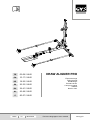 1
1
-
 2
2
-
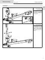 3
3
-
 4
4
-
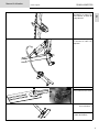 5
5
-
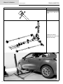 6
6
-
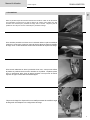 7
7
-
 8
8
-
 9
9
-
 10
10
-
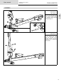 11
11
-
 12
12
-
 13
13
-
 14
14
-
 15
15
-
 16
16
-
 17
17
-
 18
18
-
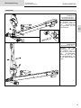 19
19
-
 20
20
-
 21
21
-
 22
22
-
 23
23
-
 24
24
-
 25
25
-
 26
26
-
 27
27
-
 28
28
-
 29
29
-
 30
30
-
 31
31
-
 32
32
-
 33
33
-
 34
34
-
 35
35
-
 36
36
-
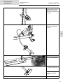 37
37
-
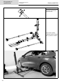 38
38
-
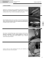 39
39
-
 40
40
-
 41
41
-
 42
42
-
 43
43
-
 44
44
-
 45
45
-
 46
46
-
 47
47
-
 48
48
-
 49
49
-
 50
50
-
 51
51
-
 52
52
-
 53
53
-
 54
54
-
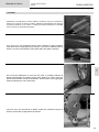 55
55
-
 56
56
-
 57
57
-
 58
58
-
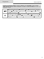 59
59
-
 60
60


en otros idiomas
- français: GYS DRAW ALIGNER PRO Manuel utilisateur
- italiano: GYS DRAW ALIGNER PRO Manuale utente
- Deutsch: GYS DRAW ALIGNER PRO Benutzerhandbuch
- Nederlands: GYS DRAW ALIGNER PRO Handleiding
Artículos relacionados
Otros documentos
-
Greenlee Ultra Tugger - Serial Code AJF Manual de usuario
-
Zipper ZI-HS16E El manual del propietario
-
 DEVILLE REGAIN 77REGAIN 77 T.RUST El manual del propietario
-
Yamaha 2000 WR450FM Owner's Service Manual
-
-
Malaguti KYMCO 150 - KY - ML 15 Manual de usuario
-
