Craftsman 247.88845 Manual de usuario
- Categoría
- Lanzadores de nieve
- Tipo
- Manual de usuario
Este manual también es adecuado para

Sears, Roebuck and Co., Hoffman Estates, IL 60179, U.S.A.
Visit our website: www.craftsman.com
CAUTION: Before using
this product, read this
manual and follow all
safety rules and operating
instructions.
Operator’s Manual
• SAFETY
• ASSEMBLY
• OPERATION
• MAINTENANCE
• PARTS LIST
• ESPAÑOL
45” SNOW THROWER
Model No. 247.88845
June 11, 2008
FORM NO. 769-04062A

2
TABLE OF CONTENTS
WARRANTY STATEMENT
PRODUCT SPECIFICATIONS MODEL NUMBER
Engine Oil Type: SAE 5W-30
Engine Oil Capacity: 28 ounces
Fuel Capacity: 4 Quarts
Spark Plug: Champion® RC12YC
Spark Plug Gap: .030”
Model Number .................................................................
Serial Number .................................................................
Date of Purchase .............................................................
Record the model number, serial number
and date of purchase above
© Sears Brands, LLC
Warranty Statement ..................................Page 2
Safe Operation Practices ..........................Pages 3-6
Safety Labels ............................................Page 7
Assembly ..................................................Pages 8-11
Operation ..................................................Pages 12-15
Service and Maintenance .........................Pages 16-23
Off-Season Storage ..................................Page 24
Troubleshooting ........................................Page 25
Parts List ...................................................Page 26-41
Repair Protection Agreement ...................Page 47
Español .....................................................Page 48
Service Numbers ......................................Back Cover
CRAFTSMAN PROFESSIONAL LIMITED WARRANTY
Two Years on Snow Thrower
When operated and maintained according to all supplied instructions, if this snow thrower fails due to a defect in material or workmanship within two years from
the date or purchase, call 1-800-4-MY-HOME® to arrange for free repair.
This warranty applies for only one year from the date of purchase if this snow thrower is ever used for commercial or rental purposes.
During the first year of purchase, there will be no charge for warranty service in your home. For your convenience, in-home warranty service will still be available
after the first year of purchase, but a trip charge will apply. This charge will be waived if you transport the snow thrower to an authorized Craftsman drop-off
location. For the nearest authorized location, call 1-800-4-MY-HOME®.
This warranty covers ONLY defects in material and workmanship. Sears will NOT pay for:
• Expendableitemsthatbecomewornduringnormaluse,includingbutnotlimitedtoskidshoes,shaveplate,shearpins,sparkplug,air
cleaner, belts, and oil filter.
• Standardmaintenanceservicing,oilchanges,ortune-ups.
• Tirereplacementorrepaircausedbypuncturesfromoutsideobjects,suchasnails,thorns,stumps,orglass.
• Tireorwheelreplacementorrepairresultingfromnormalwear,accident,orimproperoperationormaintenance.
• Repairsnecessarybecauseofoperatorabuse,includingbutnotlimitedtodamagecausedbyimpactingobjectsthatbendtheframeor
crankshaft, or over-speeding the engine.
• Repairsnecessarybecauseofoperatornegligence,includingbutnotlimitedto,electricalandmechanicaldamagecausedbyimproper
storage, failure to use the proper grade and amount of engine oil, or failure to maintain the equipment according to the instructions
contained in the operator’s manual.
• Engine(fuelsystem)cleaningorrepairscausedbyfueldeterminedtobecontaminatedoroxidized(stale).Ingeneral,fuelshouldbe
used within 30 days of its purchase date.
• Normaldeteriorationandwearoftheexteriorfinishes,orproductlabelreplacement.
This warranty applies only while this product is within the United States.
This warranty gives you specific legal rights, and you may also have other rights which vary from state to state.
Sears, Roebuck and Co., Hoffman Estates, IL 60179

3
SAFETY INSTRUCTIONS
TRAINING
Read, understand, and follow all instructions on the machine and •
inthemanual(s)beforeattemptingtoassembleandoperate.
Failuretodosocanresultinseriousinjurytotheoperatorand/
or bystanders. Keep this manual in a safe place for future and
regular reference and for ordering replacement parts. For ques-
tions call, 1-800-659-5917.
Be familiar with all controls and their proper operation. Know how •
to stop the machine and disengage them quickly.
Never allow children under 14 years of age to operate this •
machine. Children 14 and over should read and understand the
instructions and safe operation practices in this manual and on
the machine and be trained and supervised by an adult.
Never allow adults to operate this machine without proper •
instruction.
Thrownobjectscancauseseriouspersonalinjury.Planyour•
snow-throwing pattern to avoid discharge of material toward
roads, bystanders and the like.
Keep bystanders, pets and children at least 75 feet from the •
machine while it is in operation. Stop machine if anyone enters
the area.
Exercisecautiontoavoidslippingorfalling,especiallywhen•
operating in reverse.
PREPARATION
Thoroughly inspect the area where the equipment is to be used.
Remove all doormats, newspapers, sleds, boards, wires and other
foreignobjects,whichcouldbetrippedoverorthrownbytheauger/
impeller.
Always wear safety glasses or eye shields during operation and •
whileperforminganadjustmentorrepairtoprotectyoureyes.
Thrownobjectswhichricochetcancauseseriousinjurytothe
eyes.
Do not operate without wearing adequate winter outer garments. •
Donotwearjewelry,longscarvesorotherlooseclothing,which
could become entangled in moving parts. Wear footwear which
will improve footing on slippery surfaces.
Useagroundedthree-wireextensioncordandreceptacleforall•
machines with electric start engines.
Disengage all control levers before starting the engine. •
Adjustcollectorhousingheighttocleargravelorcrushedrock•
surfaces.
Neverattempttomakeanyadjustmentswhileengineisrunning,•
exceptwherespecificallyrecommendedintheoperator’smanual.
Letengineandmachineadjusttooutdoortemperaturebefore•
starting to clear snow.
WARNING
CALIFORNIA PROPOSITION 65
EngineExhaust,someofitsconstituents,andcertainvehicle
components contain or emit chemicals known to State of California
to cause cancer and birth defects or other reproductive harm.
WARNING
Your Responsibility—Restrict the use of this power machine to
persons who read, understand and follow the warnings and instruc-
tions in this manual and on the machine.
SAVE THESE INSTRUCTIONS!
WARNING
This symbol points out important safety instructions which, if not
followed,couldendangerthepersonalsafetyand/orpropertyof
yourself and others. Read and follow all instructions in this manual
before attempting to operate this machine. Failure to comply with
theseinstructionsmayresultinpersonalinjury.Whenyouseethis
symbol,HEEDITSWARNING!
DANGER
This machine was built to be operated according to the safe opera-
tion practices in this manual. As with any type of power equipment,
carelessness or error on the part of the operator can result in serious
injury.Thismachineiscapableofamputatingfingers,hands,toes
and feet and throwing debris. Failure to observe the following safety
instructionscouldresultinseriousinjuryordeath.

4
SAFETY INSTRUCTIONS
Safe Handling of Gasoline
Toavoidpersonalinjuryorpropertydamageuseextremecarein
handlinggasoline.Gasolineisextremelyflammableandthevaporsare
explosive.Seriouspersonalinjurycanoccurwhengasolineisspilled
on yourself or your clothes which can ignite. Wash your skin and
change clothes immediately.
Use only an approved gasoline container.•
Extinguishallcigarettes,cigars,pipesandothersources•
of ignition.
Never fuel machine indoors. •
Never remove gas cap or add fuel while the engine is hot •
or running.
Allow engine to cool at least two minutes before refueling.•
Never over fill fuel tank. Fill tank to no more than ½ inch •
below bottom of filler neck to provide space for fuel
expansion.
Replace gasoline cap and tighten securely.•
Ifgasolineisspilled,wipeitofftheengineandequipment.•
Move machine to another area. Wait 5 minutes before
starting the engine.
Never store the machine or fuel container inside where •
thereisanopenflame,sparkorpilotlight(e.g.furnace,
waterheater,spaceheater,clothesdryeretc.).
Allow machine to cool at least 5 minutes before storing.•
Never fill containers inside a vehicle or on a truck or trailer •
bed with a plastic liner. Always place containers on the
ground away from your vehicle before filling.
Ifpossible,removegas-poweredequipmentfromthetruck•
ortrailerandrefuelitontheground.Ifthisisnotpossible,
then refuel such equipment on a trailer with a portable
container, rather than from a gasoline dispenser nozzle.
Keep the nozzle in contact with the rim of the fuel tank or •
container opening at all times until fueling is complete. Do
not use a nozzle lock-open device.
OPERATION
Donotputhandsorfeetnearrotatingparts,intheauger/impeller•
housing or chute assembly. Contact with the rotating parts can
amputate hands and feet.
Theauger/impellercontrolleverisasafetydevice.Neverbypass•
its operation. Doing so makes the machine unsafe and may cause
personalinjury.
The control levers must operate easily in both directions and •
automatically return to the disengaged position when released.
Never operate with a missing or damaged chute assembly. Keep •
all safety devices in place and working.
Never run an engine indoors or in a poorly ventilated area. Engine •
exhaustcontainscarbonmonoxide,anodorlessanddeadlygas.
Do not operate machine while under the influence of alcohol or •
drugs.
Muffler and engine become hot and can cause a burn. Do not •
touch. Keep children away.
Exerciseextremecautionwhenoperatingonorcrossinggravel•
surfaces. Stay alert for hidden hazards or traffic.
Exercisecautionwhenchangingdirectionandwhileoperatingon•
slopes.
Plan your snow-throwing pattern to avoid discharge towards •
windows, walls, cars etc. Thus, avoiding possible property
damageorpersonalinjurycausedbyaricochet.
Never direct discharge at children, bystanders and pets or allow •
anyone in front of the machine.
Do not overload machine capacity by attempting to clear snow at •
too fast of a rate.
Never operate this machine without good visibility or light. Always •
be sure of your footing and keep a firm hold on the handles. Walk,
never run.
Disengagepowertotheauger/impellerwhentransportingornot•
in use.
Never operate machine at high transport speeds on slippery •
surfaces. Look down and behind and use care when backing up.
Ifthemachineshouldstarttovibrateabnormally,stoptheengine,•
disconnect the spark plug wire and ground it against the engine.
Inspectthoroughlyfordamage.Repairanydamagebefore
starting and operating.
Disengage all control levers and stop engine before you leave •
theoperatingposition(behindthehandles).Waituntiltheauger/
impeller comes to a complete stop before unclogging the chute
assembly,makinganyadjustments,orinspections.
Never put your hand in the discharge or collector openings. Do •
not unclog chute assembly while engine is running. Shut off
engine and remain behind handles until all moving parts have
stopped before unclogging.
Use only attachments and accessories approved by the manufac-•
turer(e.g.wheelweights,tirechains,cabsetc.).
When starting engine, pull cord slowly until resistance is felt, then •
pullrapidly.Rapidretractionofstartercord(kickback)willpull
hand and arm toward engine faster than you can let go. Broken
bones, fractures, bruises or sprains could result.
Ifsituationsoccurwhicharenotcoveredinthismanual,usecare•
andgoodjudgment.ContactCustomerSupportforassistance
and the name of your nearest servicing dealer.
CLEARING A CLOGGED DISCHARGE CHUTE
Hand contact with the rotating impeller inside the discharge chute
isthemostcommoncauseofinjuryassociatedwithsnowthrowers.
Never use your hand to clean out the discharge chute.
To clear the chute:
SHUTTHEENGINEOFF!1.
Wait 10 seconds to be sure the impeller blades have stopped 2.
rotating.
Always use a clean-out tool, not your hands.3.

5
SAFETY INSTRUCTIONS
MAINTENANCE & STORAGE
Never tamper with safety devices. Check their proper operation •
regularly.Refertothemaintenanceandadjustmentsectionsof
this manual.
Before cleaning, repairing, or inspecting machine disengage all •
controlleversandstoptheengine.Waituntiltheauger/impeller
come to a complete stop. Disconnect the spark plug wire and
ground against the engine to prevent unintended starting.
Check bolts and screws for proper tightness at frequent intervals •
to keep the machine in safe working condition. Also, visually
inspect machine for any damage.
Do not change the engine governor setting or over-speed the •
engine.Thegovernorcontrolsthemaximumsafeoperatingspeed
of the engine.
Snowthrowershaveplatesandskidshoesaresubjecttowear•
and damage. For your safety protection, frequently check all
components and replace with original equipment manufacturer’s
(OEM)partsonly.“Useofpartswhichdonotmeettheoriginal
equipment specifications may lead to improper performance and
compromisesafety!”
Check control levers periodically to verify they engage and disen-•
gageproperlyandadjust,ifnecessary.Refertotheadjustment
section in this operator’s manual for instructions.
Maintain or replace safety and instruction labels, as necessary.•
Observe proper disposal laws and regulations for gas, oil, etc. to •
protect the environment.
Prior to storing, run machine a few minutes to clear snow from •
machineandpreventfreezeupofauger/impeller.
Never store the machine or fuel container inside where there is an •
open flame, spark or pilot light such as a water heater, furnace,
clothes dryer etc.
Always refer to the operator’s manual for proper instructions on •
off-season storage.
Check fuel line, tank, cap, and fittings frequently for cracks or •
leaks. Replace if necessary.
Do not crank engine with spark plug removed.•
AccordingtotheConsumerProductsSafetyCommission(CPSC)•
andtheU.S.EnvironmentalProtectionAgency(EPA),thisproduct
has an Average Useful Lifeofseven(7)years,or60hoursof
operation. At the end of the Average Useful Life have the machine
inspected annually by an authorized service dealer to ensure that
all mechanical and safety systems are working properly and not
wornexcessively.Failuretodosocanresultinaccidents,injuries
or death.
DO NOT MODIFY ENGINE
Toavoidseriousinjuryordeath,donotmodifyengineinanyway.
Tampering with the governor setting can lead to a runaway engine and
cause it to operate at unsafe speeds. Never tamper with factory setting
of engine governor.
NOTICE REGARDING EMISSIONS
Engines which are certified to comply with California and federal
EPAemissionregulationsforSORE(SmallOffRoadEquipment)are
certified to operate on regular unleaded gasoline, and may include
thefollowingemissioncontrolsystems:EngineModification(EM),
OxidizingCatalyst(OC),SecondaryAirInjection(SAI)andThreeWay
Catalyst(TWC)ifsoequipped.
SPARK ARRESTOR
Ifasparkarresterisused,itshouldbemaintainedineffectiveworking
orderbytheoperator.IntheStateofCaliforniatheaboveisrequired
bylaw(Section4442oftheCaliforniaPublicResourcesCode).Other
states may have similar laws. Federal laws apply on federal lands.
A spark arrester for the muffler is available through your nearest Sears
Parts and Repair Service Center.
WARNING
This machine is equipped with an internal combustion engine and
should not be used on or near any unimproved forest-covered,
brush-coveredorgrass-coveredlandunlesstheengine’sexhaust
system is equipped with a spark arrester meeting applicable local or
statelaws(ifany)

6
SAFETY INSTRUCTIONS
SAFETY SYMBOLS
This page depicts and describes safety symbols that may appear on this product. Read, understand, and follow all instructions on the machine
before attempting to assemble and operate.
Symbol Description
READ THE OPERATOR’S MANUAL(S)
Read, understand, and follow all instructions in the manual(s) before attempting to assemble and
operate
WARNING— ROTATING BLADES
Keep hands out of inlet and discharge openings while machine is running. There are rotating blades
inside
WARNING— ROTATING BLADES
Keep hands out of inlet and discharge openings while machine is running. There are rotating blades
inside
WARNING— ROTATING AUGER
Do not put hands or feet near rotating parts, in the auger/impeller housing or chute assembly.
Contact with the rotating parts can amputate hands and feet.
WARNING—THROWN OBJECTS
This machine may pick up and throw and objects which can cause serious personal injury.
WARNING—GASOLINE IS FLAMMABLE
Allow the engine to cool at least two minutes before refueling.
WARNING— CARBON MONOXIDE
Never run an engine indoors or in a poorly ventilated area. Engine exhaust contains carbon
monoxide, an odorless and deadly gas.
WARNING— ELECTRICAL SHOCK
Do not use the engine’s electric starter in the rain

7
SAFETY LABELS
KEEP AWAY FROM ROTATING IMPELLER
AND AUGER. CONTACT WITH IMPELLER OR
AUGER CAN AMPUTATE HANDS AND FEET
.
USE CLEAN-OUT TOOL TO UNCLOG
DISCHARGE CHUTE.
DISENGAGE CLUTCH LEVERS, STOP ENGINE ,
AND REMAIN BEHIND HANDLES UNTIL ALL
MOVING PARTS HAVE STOPPED BEFORE
UNCLOGGING OR SERVICING MACHINE.
TO AVOID THROWN OBJECTS INJURIES,
NEVER DIRECT DISCHARGE AT BYSTANDERS.
USE EXTRA CAUTION WHEN OPERATING ON
GRAVEL SURFACES.
READ OPERATOR'S MANUAL.
1.
2.
3.
4.
5.
DANGER
CLEAN-OUT TOOL
DANGER
AVOID INJURY FROM
ROTATING AUGER -
KEEP HANDS, FEET
AND CLOTHING AWAY.
DANGER
NEVER PUT HAND IN CHUTE. CONTACT WITH
ROTATING PARTS CAN AMPUTATE FINGERS
AND HANDS.
SHUT OFF ENGINE AND WAIT UNTIL AL L
MOVING PARTS HA VE STOPPED BEFORE
UNCLOGGING.
USE CLEAN-OUT TOOL OR WOODEN
STICK TO
UNCLOG DISCHARGE CHUTE.

8
ASSEMBLY
NOTE: References to right or left side of the snow thrower are
determinedfrombehindtheunitintheoperatingposition(standing
directlybehindthesnowthrower,facingthehandlepanel).
REMOVING FROM CRATE
Remove screws 1. from the bottom of the crate securing the sides,
and ends of the shipping crate.
Lift off the top off of the crate and set out of the way of the 2.
assembly area.
Remove and discard plastic bag that covers unit.3.
Removeanyloosepartsincludedwithunit(e.g.,Operator’s4.
Manual,etc.).
Push down on the lower handle and pull unit back out of crate.5.
Make certain the crate has been completely emptied before 6.
discarding it.
ASSEMBLY
Make certain the springs at the lower end of the auger and drive 1.
cables are securely hooked into their respective actuator
bracket before pivoting the handle upward. Refer to Fig. 10.
a. Place the shift lever in the F6 position.
b. Remove the lower wing knob and carriage bolt from each
side of the upper handle. Pull up on upper handle as shown
in Fig. 1. Align upper handle with the lower handle. Again,
make certain the springs at the lower end of the auger and
drive cables are securely hooked into their respective
actuator bracket. Also, remove any rubber bands securing
the cables to the wing nuts.
2. a. Secure the upper handle and lower handle with the two wing
knobs and carriage bolts removed earlier.
b. Tighten the two wing knobs already installed in the upper
holes to firmly secure the upper handle and support tubes.
3. Align the upper and lower shift rods, then slide the shift rod
connector down over the end of the lower shift rod. Tap the
connector until the lower rod is completely through the connector.
See Fig. 2.
NOTE:Iftheconnectorisnotproperlyassembled,theshiftrodwill
pivot and you will not be able to properly change speeds or direction.
NOTE:Ifthefullrangeofspeeds(forwardandreverse)cannotbe
achieved,refertothe“MakingAdjustments”section.
4. a. Cut the cable tie securing the chute assembly to the lower
chute crank rod for shipping purposes.
b. Remove the internal cotter pin from the upper chute crank.
Slide the upper chute crank into the sleeve on the lower
chute crank. See Fig. 3.
c. Align the hole in the upper chute crank with the hole in the
sleeve(Ifnecessary,useapairofplierstoassistinaligning
holes).Inserttheinternalcotterpinthroughtheholesto
secure the chute crank. See Fig. 3.
Remove lock nuts and screws securing one of the flange keepers 5.
to the chute assembly.
Figure 1
Figure 2
a
b
Figure 3

9
ASSEMBLY
Place chute assembly onto chute base as shown in Fig. 4, 6.
making sure that the notches engage with the spiral end of chute
directional control.
Secure flange keeper removed earlier with lock nuts and screws. 7.
Tighten down nuts securing the other two flange keepers. See Fig. 5.
Ifnotalreadydone,slipthecablesthatrunfromthehandle8.
paneltothedischargechuteintothecableguideextendingover
the top of the engine. See Fig. 4.
Normally the cable ties holding the steering cables against the 9.
handle are loosely installed on each side of the lower handle at
thefactory.Pullthecabletiestighttosecure.Cuttheexcess
from the ends of cable ties.
Theextensioncordisfastenedwithacabletietotherearoftheauger
housing for shipping purposes. Cut the cable tie and remove it before
operating the snow thrower.
SET-UP
Chute Clean-Out Tool
A chute clean-out tool is fastened to the top of the auger housing
with a mounting clip. See Fig. 6. The tool is designed to clear a chute
assemblyoficeandsnow.Thisitem,alongwiththeextensioncord,is
fastened with a cable tie at the factory, which you were instructed to
cut in the previous section.
Drift Cutters
Remove the two screws and lock nuts that secure each drift 1.
cutter, and remove them from the sides of the auger housing.
Turn the drift cutters around and position them as shown in Fig. 7 2.
to the outside of the auger housing.
Attach the drift cutters with the screws and lock nuts removed 3.
earlier.
Figure 5
Figure 4
Figure 6
WARNING
Never use your hands to clear a clogged chute assembly. Shut
off engine and remain behind handles until all moving parts have
stopped before using the clean-out tool to clear the chute assembly.
Figure 7
Chute Clean-out Tool

10
ASSEMBLY
Tire Pressure
Before operating, check tire pressure. Refer to the tire sidewall for
exacttiremanufacturer’srecommendedormaximumpsi.
NOTE:Ifthetirepressureisnotequalinbothtires,theunitmaynot
travel in a straight path and the shave plate may wear unevenly.
ADJUSTMENTS
Skid Shoes
Thesnowthrowerskidshoesareadjustedupwardatthefactoryfor
shippingpurposes.Adjustthemdownward,ifdesired,priortooperat-
ing the snow thrower.
For close snow removal on a smooth surface, raise skid shoes •
higher on the auger housing.
Use a middle or lower position when the area to be cleared is •
uneven.
NOTE:Ifyouchoosetooperatethesnowthroweronagravelsurface,
keeptheskidshoesinpositionformaximumclearancebetweenthe
ground and the shave plate.
Figure 8
CAUTION
Itisnotrecommendedthatyouoperatethissnowthrowerongravel
as it can easily pick up and throw loose gravel, causing personal
injuryordamagetothesnowthrowerandsurroundingproperty.
Toadjusttheskidshoes:
Loosen the 1. sixhexnuts(threeoneachside)andcarriagebolts.
Move skid shoes to desired position. See Fig. 8.
Make certain the entire bottom surface of skid shoe is against the 2.
ground to avoid uneven wear on the skid shoes.
Retighten nuts and bolts securely.3.
Figure 9
Drive
Control
Drive
Control
Cable
Auger
Control
Auger
Control
Cable
Shift Lever
Chute Tilt Control

11
ASSEMBLY
Ifadjustingtheaugercable,threadthelocknutdownthecoupler4.
towards the end of the thread to lengthen the cable as necessary
to stop the auger from turning when the control is released.
Reattach the spring to the 5. rearmost hole in the actuator bracket.
Repeat the wheel drive and auger control tests to verify proper 6.
adjustment.Repeatpreviousstepsifnecessarytoattainproper
adjustmentofeachcable.
Testing Auger Drive Control
Whentheaugercontrolisreleasedandinthedisengaged“up”posi-
tion, the cable should have very little slack, but should NOT be tight.
Refer to Fig. 9 for location of controls.
Inawell-ventilatedarea,startthesnowthrowerengineas1.
instructed in the Operation section.
Whilestandingintheoperator’sposition(behindthesnow2.
thrower),engagetheaugercontrolandallowtheaugertoremain
engagedforapproximatelytensecondsbeforereleasingthe
auger control. Repeat this several times.
With the engine running and the auger control in the disengaged 3.
“up”position,walktothefrontofthemachine.Confirmthatthe
auger has completely stopped rotating and shows no signs of
motion.
Iftheaugershowsanysignsofrotating,immediatelyreturntothe4.
operator’s position and shut off the engine. Wait for all moving
partstostopbeforereadjustingtheaugercontrolcable.
Testing Wheel Drive Control & Speed Selector
Shift Lever
Refer to Fig. 9 for location of controls.
Movetheshiftleverintosixth(6)position.1.
With the wheel drive control released, push the snow thrower 2.
forward, then pull it back. The machine should move freely.
Engage the drive control and attempt to move the machine both 3.
forward and back, resistance should be felt.
Movetheshiftleverintothefastreverse(R2)positionandrepeat4.
the previous two steps.
Ifyouexperiencedresistancerollingtheunit,eitherwhenrepositioning
the shift lever from 6 to R2 or when attempting to move the machine
withthedrivecontrolreleased,adjustthedrivecontrolimmediately.
SeeAdjustingDriveandAugerControls.
Adjusting Wheel Drive & Auger Controls
From beneath the handle, pull downward on the appropriate cable 1.
and unhook the spring found on the end of the cable from its
respective actuator bracket. Refer to Fig. 9 and 10.
Slidethespringupthecabletoexposethecablecouplerthreads2.
and lock nut. Refer to Fig. 11.
Ifadjustingthedrivecable,threadthelocknutoutward(downthe3.
couplertowardstheendfothethread)tolengthenthecableand
allow the unit to move freely when the control is released. Thread
thelocknutinward(upthecouplertowardsthecable)toshorten
the cable to reduce slippage and prevent the machine from being
easily moved with the drive control engaged.
Figure 10
WARNING
Prior to operating your snow thrower, carefully read and follow all
instructionsbelow.Performalladjustmentstoverifyyoursnow
thrower is operating safely and properly.
Figure 11
WARNING
Do not over-tighten the cable. Over-tightening may prevent the auger
from disengaging and compromise the safety of the snow thrower.

12
OPERATION
Now that you have setup your snow thrower, it’s important to become
acquainted with its controls and features. Refer to Figure 11.
SPEED SELECTOR SHIFT LEVER
The shift lever is located on the right side of the handle panel.
Place the shift lever into any of eight positions to control the
direction of travel and ground speed.
Forward
Yoursnowthrowerhassixforward(F)speeds.Positionone(1)is
theslowestandpositionsix(6)isthefastest.
Reverse
Yoursnowthrowerhastworeverse(R)speeds.One(1)isthe
slowerandtwo(2)isthefaster.
IGNITION KEY
Theignitionkeyisasafetydevice.Itmustbefullyinsertedinorderfor
the engine to start. Remove the ignition key when the snow thrower is
not in use.
NOTE: Do not turn the ignition key in an attempt to start the engine.
Doing so may cause it to break.
CHOKE CONTROL
The choke control is found on the rear of the
engine and is activated by rotating the knob
clockwise. Activating the choke control closes the
choke plate on the carburetor and aids in starting
the engine.
PRIMER
Depressing the primer forces fuel directly into the engine’s carburetor
to aid in cold-weather starting.
OIL FILL
Engine oil level can be checked and oil added through the oil fill.
Figure 11
Meets ANSI Safety Standards
CraftsmanSnowThrowersconformtothesafetystandardoftheAmericanNationalStandardsInstitute(ANSI).
Drive Control
Headlight
Oil Fill
Fuel Cap
Primer
Choke
Ignition
Key
Oil Drain
Starter
Button
Electric Starter Outlet
Recoil Starter
Handle
Chute
Assembly
Drift
Cutters
Clean-Out Tool
Auger Control
Shift Lever
Two-Way Chute Control™
Wheel Steering
Control
Chute Directional
Control
Skid Shoe
Augers

13
OPERATION
ON / OFF SWITCH
Press into the ON position when starting the engine and will shut off
the engine when moved into the OFF position.
RECOIL STARTER HANDLE
This handle is used to manually start the engine.
ELECTRIC STARTER BUTTON
Pressing the electric starter button engages the engine’s electric
starter when plugged into a 120V power source.
ELECTRIC STARTER OUTLET
Requirestheuseofathree-prongoutdoorextensioncord(included)
anda120Vpowersource/walloutlet.
AUGERS
When engaged, the augers rotate and draw snow into the auger
housing.
CHUTE ASSEMBLY
Snow drawn into the auger housing is discharged out the chute
assembly.
GAS CAP
Unthread the gas cap to add gasoline to the fuel tank.
AUGER CONTROL
The auger control is located on the left handle. Squeeze the control
grip against the handle to engage the augers and start snow throwing
action. Release to stop.
WHEEL DRIVE CONTROL /AUGER CONTROL
LOCK
The wheel drive control is located on the right handle. Squeeze the
control grip against the handle to engage the wheel drive. Release
to stop. The Wheel drive control also locks the auger control so you
can operate the chute directional control without interrupting the snow
throwingprocess.Iftheaugercontrolisengagedsimultaneouslywith
thewheeldrivecontrol,theoperatorcanreleasetheaugercontrol(on
thelefthandle)andtheaugerswillremainengaged.Releaseboth
controls to stop the augers and wheel drive.
NOTE: Always release the wheel drive control before changing
speeds. Failure to do so will result in increased wear on your machine’s
drive system.
TWO-WAY CHUTE CONTROL™
Thedistancesnowisthrowncanbechangedbyadjustingtheangle
of the chute assembly. Move the chute control forward to decrease the
distance, toward the rear to increase.
CHUTE DIRECTIONAL CONTROL
The chute directional control is located on the left side of the snow
thrower.
To change the direction in which snow is thrown, crank clockwise to •
discharge to the left and counterclockwise to discharge to the right.
SKID SHOES
Positiontheskidshoesbasedonsurfaceconditions.Adjustupward
forhard-packedsnow.Adjustdownwardwhenoperatingongravelor
crushed rock surfaces.
WHEEL STEERING CONTROLS
The left and right wheel steering controls are located on the underside
of the handles. Squeeze the right control to turn right; squeeze the left
control to turn left.
NOTE: Operate the snow thrower in open areas until you are familiar
with these controls.
HEADLIGHT
Theheadlightislocatedontopofthehandlepanel.Itmaybeadjusted
by loosening the screws on each side of the light housing, pivoting the
light up or down, and retightening the screws.
DRIFT CUTTERS
The drift cutters are designed for use in deep snow. Their use is
optional for normal snow conditions.
CLEAN-OUT TOOL
The chute clean-out tool is conveniently fastened to the rear of the
auger housing with a mounting clip. Should snow and ice become
lodged in the chute assembly during operation, proceed as follows to
safely clean the chute assembly and chute opening.
AUGER
CONTROL
GO
DRIVE
CONTROL
GO

14
OPERATION
CLEAN-OUT TOOL
The chute clean-out tool is conveniently fastened to the rear of the
auger housing with a mounting clip. Should snow and ice become
lodged in the chute assembly during operation, proceed as follows to
safely clean the chute assembly and chute opening:
Release both the Auger Control and the Wheel drive control.1.
Stop the engine by removing the ignition key. 2.
Remove the clean-out tool from the clip which secures it to the 3.
rear of the auger housing.
Use the shovel-shaped end of the clean-out tool to dislodge and 4.
scoop any snow and ice which has formed in and near the chute
assembly.
Refasten the clean-out tool to the mounting clip on the rear of 5.
the auger housing, reinsert the ignition key and start the snow
thrower’s engine.
Whilestandingintheoperator’sposition(behindthesnow6.
thrower),engagetheaugercontrolforafewsecondstoclearany
remaining snow and ice from the chute assembly.
BEFORE STARTING ENGINE
Oil
The unit was shipped with oil in the engine. Check oil level before each
operation to ensure adequate oil in the engine. For further instructions,
refer to the Service & Maintenance section of this manual.
Remove the dipstick from the oil fill. 1.
Check and make sure that the level of oil is up to the FULL mark 2.
on the dipstick.
IftheoillevelisnotuptoFULL,pourfreshmotoroil(5W-30,with3.
aminimumclassificationofSF/SG/SH/SJ)slowlythroughthe
opening. Replace oil fill dipstick and check oil level again.
Gasoline
Store gasoline in a clean, approved container and keep the cap in •
place on the container.
Make sure that the container from which you pour the gasoline is •
clean and free from rust or other foreign particles.
NOTE: A plastic dust cap may be found inside the fuel fill opening.
Remove and discard, if present.
Always fill the fuel tank outdoors and use a funnel or spout to •
prevent spilling.
Fill fuel tank with clean, fresh, unleaded gasoline with a minimum •
of 85 octane. Fresh fuel prevents gum from forming in the fuel
system or on essential carburetor parts. Purchase fuel in a
quantity that can be used within 30 days.
Neverfillthefueltankcompletely.Fillthetanktowithin1-1/2”•
fromthetoptoprovidespaceforexpansionoffuel.
Make sure to wipe off any spilled fuel before starting the engine.•
STARTING THE ENGINE
Make certain both the auger control and wheel drive control are in 1.
thedisengaged(released)position.
Insertignitionkeyintoslot.Makesureitsnapsintoplace.Donot2.
attempt to turn the key.
NOTE: The engine cannot start without the key is fully inserted into the
ignition switch.
Electric Starter
Determine that your home’s wiring is a three-wire grounded system.
Ask a licensed electrician if you are not certain.
Ifyouhaveagroundedthree-prongreceptacle,proceedasfollows:
Plugtheextensioncordintotheoutletlocatedontheengine’s1.
surface.Plugtheotherendofextensioncordintoathree-prong
120-volt, grounded, AC outlet in a well-ventilated area.
Rotate choke control to FULL 2. chokeposition(foracold
enginestart).
NOTE:Iftheengineisalreadywarm,placechokecontrolintheOFF
position instead of FULL .
Depressprimer.Ifitis15°Forhigherpushprimertwotimes,if3.
below15°F,pushprimerfourtimes.
Push rocker switch to ON position.4.
Push starter button to start engine.5.
CAUTION
Toprolongstarterlife,useshortstartingcycles(5secondsmaximum,
thenwaitoneminute).
Once the engine starts, release starter button.6.
Allowtheenginetowarmupseveralminutes,adjustingchoke7.
toward RUN position. Wait until engine runs smoothly before each
chokeadjustment.
Whendisconnectingtheextensioncord,alwaysunplugtheend8.
at the three-prong wall outlet before unplugging the opposite end
from the snow thrower.
WARNING
Never use your hands to clear a clogged chute assembly. Shut
off engine and remain behind handles until all moving parts have
stopped before unclogging.
WARNING
Read, understand, and follow all instructions and warnings on the
machine and in this manual before operating.
WARNING
Useextremecarewhenhandlinggasoline.Gasolineisextremely
flammableandthevaporsareexplosive.Never fuel the machine
indoorsorwhiletheengineishotorrunning.Extinguishcigarettes,
cigars, pipes and other sources of ignition.
WARNING
The optional electric starter is equipped with a grounded three-wire
power cord and plug, and is designed to operate on 120 volt AC
householdcurrent.Itmustbeusedwithaproperlygroundedthree-
prong receptacle at all times to avoid the possibility of electric shock.
Follow all instructions carefully prior to operating the electric starter.

15
OPERATION
Recoil Starter
Rotate choke control to CHOKE 1. position.
Depressprimer.Ifitis15°Forhigherpushprimertwotimes,if2.
below15°F,pushprimerfourtimes.
Push rocker switch to ON position.3.
Grasp the recoil starter handle and slowly pull the rope out. At 4.
the point where it becomes slightly harder to pull the rope, slowly
allow the rope to recoil.
Pull the starter handle with a firm, rapid stroke. Do not release 5.
the handle and allow it to snap back. Keep a firm hold on the
starter handle and allow it to slowly recoil.
Allowtheenginetowarmupseveralminutes,adjustingchoke6.
toward RUN position. Wait until engine runs smoothly before each
chokeadjustment.
STOPPING THE ENGINE
Run engine for a few minutes before stopping to help dry off any
moisture on the engine.
PushtheOn/OffswitchtotheOFFposition.1.
CAUTION
Do NOT move the choke control to CHOKE position to stop
the engine. Backfire or engine damage may occur.
Remove the ignition key and store in a safe place.2.
Wipe all snow and moisture from the area around the engine as 3.
well as the area in and around the wheel drive control and auger
control. Also, engage and release both controls several times.
TO ENGAGE WHEEL DRIVE
Moveshiftleverintooneofthesixforward(F)positionsortwo1.
reverse(R)positions.Selectaspeedappropriateforthesnow
conditions and a pace you’re comfortable with.
NOTE: When selecting a Drive Speed, use the slower speeds until
you are comfortable and familiar with the operation of the snow
thrower.
Squeeze the wheel drive control against the handle the snow 2.
thrower will move. Release it and drive motion will stop.
NOTE: NEVERrepositiontheshiftlever(changespeedsordirection
oftravel)withoutfirstreleasingthewheeldrivecontrolandbringing
the snow thrower to a complete stop. Doing so will result in premature
wear to the snow thrower’s drive system.
TO ENGAGE AUGERS
To engage the augers and start throwing snow, squeeze the 1.
auger control against the left handle. Release to stop the augers.
REPLACING SHEAR PINS
The augers are secured to the spiral shaft with two shear pins and cot-
terpins.Iftheaugershouldstrikeaforeignobjectoricejam,thesnow
throwerisdesignedsothattheshearpinsmayshear.Iftheaugerswill
not turn, check to see if the pins have sheared. See Figure 12.
CAUTION
NEVER replace the auger shear pins with anything other than OEM
Part No. 738-04155 replacement shear pins. Any damage to the
augergearboxorothercomponentsasaresultoffailingtodosowill
NOT be covered by your snow thrower’s warranty.
WARNING
Always turn off the snow thrower’s engine and remove the key prior to
replacing shear pins.
Figure 12

16
SERVICE AND MAINTENANCE
ENGINE MAINTENANCE
Checking Engine Oil
Be sure engine is upright and level1.
Unscrew oil fill cap from oil filler tube and wipe dipstick clean.2.
Screw oil fill cap back into oil filler tube. Tighten securely.3.
Unscrew and remove oil fill cap from oil filler tube. Note oil level. 4.
Ifoilreadingondipstickisbelow“ADD”mark,slowlyaddoilto
reach“FULL”level.SeeFigure13.
Screw oil fill cap back into oil filler tube. Tighten securely.5.
Wipe away any spilled oil.6.
Changing Engine Oil
To avoid engine damage, it is important to:
Check oil level before each use and every eight operating hours.•
Change oil after first 5 to 8 operating hours and every 50 operat-•
ing hours or once a season thereafter.
Place engine level and remove safety key.1.
With engine OFF but still warm, remove oil drain plug and drain oil 2.
into an appropriate receptacle. See Figure 13.
CAUTION
Used oil is a hazardous waste product. Dispose of used oil properly.
Do not discard with household waste. Check with your local authori-
tiesorSearsServiceCenterforsafedisposal/recyclingfacilities.
Reinstall oil drain plug and tighten securely.3.
Refill the engine with recommended oil. See Recommended Oil 4.
Usage chart. The engine’s oil capacity is 20 ounces.
-20 F
O
32 F
O
32 F
O
40 F
O
-20 C
O
20 F
O
40 C
O
30 C
O
20 C
O
10 C
O
0 C
O
-10 C
O
-30 C
O
0 F
O
60 F
O
80 F
O
100 F
O
Recommended Oil Usage
5W-30, 10W-30
Synthetic 5W-30, 10W-30
Wipe away any spilled oil.5.
Checking Spark Plug
Figure 13
FULL
ADD
Maintain oil level
at FULL
Figure 14
Oil FIll
Oil Drain
WARNING
Before lubricating, repairing, or inspecting, disengage all controls and
stop engine. Wait until all moving parts have come to a complete stop.
Remove the ignition key to prevent unintended firing of the engine.

17
SERVICE AND MAINTENANCE
Check spark plug yearly or every 100 operating hours.
Remove choke control knob and safety key.1.
Loosen and remove the mounting screws from the snow hood.2.
Slowly remove the snow hood, making sure that the primer bulb 3.
hose and ignition wire remain connected. See Figure 15.
Remove and inspect spark plug.4.
Replace spark plug if porcelain is cracked or if electrodes are 5.
pitted, burned or fouled with deposits.
Check electrode gap with a feeler gauge and set gap to .030 6.
(0.76mm)ifnecessary.SeeFigure16.
Reinstall spark plug and tighten securely.7.
Remount the snow hood to the engine with the mounting screws, 8.
again making sure the primer bulb hose and ignition wire are
connected.
Connect the choke control knob to the choke shaft on the 9.
carburetor.Ifthechokecontrolknobisnotinstalledcorrectly,the
choke will not operate.
Installthesafetykey.10.
NOTE: A resistor spark plug must be used for replacement. Contact a
Sears Parts and Repair Center for a replacement spark plug.
Carburetor
Enginesoperatedatabout3000to5000feet(900to1500meters)
abovesealevelmayrequireahighaltitudecarburetormainjet.If
erratic performance is observed, contact a Sears Parts and Repair
Centerforcosttoinstall/purchaseahighaltitudecarburetormainjet.
Engine Speed
LUBRICATION
Drive and Shifting Mechanism
At least once a season or after every 25 hours of operation, remove
rear cover. Lubricate all chains, sprockets, gears, bearings, shafts, and
the shifting mechanism. Use engine oil or a spray lubricant. Refer to
Figure 17.
NOTE: Be careful not to get any oil on the aluminum drive plate or
rubber friction wheel. Doing so will hinder the snow thrower’s drive
system.Wipeoffanyexcessorspilledoil.
Wheels
Atleastonceaseason,removebothwheels.Cleanandcoattheaxles
with a multipurpose automotive grease before reinstalling wheels.
Chute Directional Control
Once a season, lubricate the eye bolt bushing and the spiral with
3-in-1 oil.
Figure 16
2
3
1
1. .030(.76mm)Gap
2. Electrodes
3. Porcelain
WARNING
Avoidseriousinjuryordeath,DONOTmodifyengineinanyway.
Tampering with the governor setting can cause the engine and
equipment to operate at unsafe speeds. NEVER tamper with factory
setting of engine governor. Running the engine faster than the speed
set at the factory is dangerous.
Figure 17
Figure 15
Mounting
Screws
Choke Control
Knob
Snow Hood
Spark Plug
Hex Shaft

18
SERVICE AND MAINTENANCE
Auger Shaft
At least once a season, remove the shear pins on auger shaft. Spray
lubricant inside shaft, and around the spacers and flange bearings
found at either end of the shaft. See Figure 18.
SHAVE PLATE AND SKID SHOES
The shave plate and skid shoes on the bottom of the snow thrower are
subjecttowear.Theyshouldbecheckedperiodicallyandreplaced
when necessary.
Skid Shoes
NOTE: The skid shoes on this machine have two wear edges. When
onesidewearsout,theycanberotated180°tousetheotheredge.
Removethesixcarriageboltsandhexnutsthatsecurethetwo1.
skid shoes to the sides of the auger housing. Refer to Figure 19.
Position the new skid shoes and secure with the carriage bolts 2.
andhexnuts.Makecertaintheskidshoesareadjustedtobe
level.
Shave Plate
Removethehexnutsandcarriageboltsthatsecuretheshave1.
plate to the bottom of the housing.
Removetherearmosthexnutandcarriageboltsecuringtheback2.
of each skid shoe to the sides of the housing. Loosen the four
remaininghexnutssecuringtheskidshoes.
Slide the shave plate out of the off-set slot at the bottom of the 3.
housing, and from between the skid shoes and side panels of the
housing.
With the mounting holes toward the back of the unit, slide the new 4.
shave plate into position and secure with the fasteners removed
previously.
ADJUSTMENTS
Shift Rod
Ifthefullrangeofspeeds(forwardandreverse)cannotbeachieved,
refertoFigure20totheleftandadjusttheshiftrodasfollows:
Looking underneath the handle panel, note which of the three 1.
holes in the shift lever the ferrule is inserted into. Also note the
direction of insertion. Then remove the internal cotter pin and flat
washer from the ferrule and withdraw the ferrule from the shift
lever. See Figure 20.
Placeshiftleverinsixth(6)positionorfastestforwardspeed.2.
Push shift rod and shift arm assembly down sharply as far as it 3.
will go to put the drive into the fastest forward position.
As necessary, rotate the ferrule up or down the shift rod until the 4.
ferrule lines up with the hole from which it was earlier removed.
See Figure 20.
From the direction noted earlier, insert the ferrule into the proper hole. 5.
Reinstall the washer and the internal cotter pin.6.
Chute Control
Thedistancesnowisthrowncanbeadjustedbyadjustingtheangleof
the chute assembly. Refer to the Operation section for instructions.
Theremotechutecontrolcableshavebeenpre-adjustedatthefactory.
Figure 19
Figure 20
Figure 18

19
SERVICE AND MAINTENANCE
Move the remote chute lever on the control panel forward to pivot the
upper chute down; move the lever rearward to pivot the upper chute
up.
Wheel drive control
RefertotheAdjustmentsectionoftheAssemblyinstructionstoadjust
thewheeldrivecontrol.Tofurtherchecktheadjustment,proceedas
follows:
Withthesnowthrowertippedforward(becertaintorunthe1.
fueltankdrybeforetippingtheunitforward),removetheframe
cover underneath the snow thrower by removing the self-tapping
screws.
Locatetheopeningbetweentheaxlesupportbracketand2.
thefrontframesupport(SeeFigure21).Lookingthroughthis
opening, with the wheel drive control released, there must be
clearance between the friction wheel and the drive plate in all
positions of the shift lever.
With the wheel drive control engaged, the friction wheel must 3.
contact the drive plate. See Figure 21.
Ifthereisnofrictionwheelclearance,orthefrictionwheeldoes4.
notsolidlycontactthedriveplate,re-adjustthelocknutonthe
lower end of the drive cable following the instructions in the
Assembly section.
Reassemble the frame cover.5.
Chute Bracket
Ifthespiralatthebottomofthechutedirectionalcontrolisnotfully
engagingwiththechuteassembly,thechutebracketcanbeadjusted.
To do so:
Loosen the two nuts which secure the chute bracket and reposi-1.
tion it slightly. See Figure 22.
Retighten the nuts.2.
Auger Control
RefertotheAssemblysectionforinstructionsonadjustingtheauger
control cable.
Skid Shoes
RefertotheAssemblysectionforinstructionsonadjustingtheskid
shoes.
BELT REPLACEMENT
Belt Removal Preparation
Disconnect the chute crank assembly at the discharge chute end 1.
by removing the hairpin clip and the flat washer. Refer to Figure
23.
Remove the plastic belt cover, located near the engine, by remov-2.
ing the three self-tapping screws that secure it. See Figure 24.
Loosen the bolt shown in Figure 25 securing the belt keeper 3.
bracket and remove the other bolt. Push the belt keeper and
bracket up off the engine pulley.
Auger Belt Replacement
Remove the hairpin clip and flat washer from the ferrule in order to 1.
disconnect the auger idler rod from the brake bracket assembly.
Figure 21
Figure 22
Figure 23
Axle Supp.
Brkt.
Opening
Drive
Plate
Friction
Wheel

20
SERVICE AND MAINTENANCE
See Figure 26.
NOTE: Make sure that the location of the ferrule on the auger
idler rod is maintained.
Sliptheaugercontrolbelt(thefrontbelt)offtheenginepulley.2.
Pull the 3. brake bracket assembly towards the cable guide roller
andunhooktheaugercable“Z”fitting.SeeFigure27.
Frombothsidesofthetheframeassembly,usea1/2”wrenchto4.
removethethreehextapscrewssecuringtheframetotheauger
housing assembly. Refer to Figure 23 on previous page.
NOTE:Donotremovethelowerhexflangelocknutoneachside.
5. Place a block of wood underneath the auger housing as shown in
Figure 28 and separate auger housing from the frame by tilting the
housing forward and pulling up the handles.
Block the impeller with a piece of wood to prevent it from spinning 6.
andusea1/2”wrenchtoremovethehexscrewandflatwasher
from the center of the pulley on the auger housing. See Figure 29.
Lift the brake bracket assembly out of the pulley groove and slide 7.
the pulley assembly off the posts of the auger pulley adapter to
remove the old belt. Refer to Figure 29.
NOTE: The pulley adapter may slide off the auger input shaft when
removingthepulley.Useextracautiontoensuretheadapterdoesfall
and/orgetdamagedwhenremovingthepulley.
8. Place the new auger belt in the V-groove of the auger pulley and
placethepulleyw/beltinsidethebeltkeepers.
9.Turnthepulleyasnecessarytoalignitsthreeslotsapproximately
with the posts of the pulley adapter, then move the brake bracket
assembly away from the input shaft. While aligning the pulley
slots and adapter posts, push the auger pulley fully onto the
adapter. Refer to Figure 29.
NOTE:Ifthepulleyadapterwasremovedwiththepulley,alignthe
splines of the pulley adapter and auger input shaft, and push the pulley
and adapter onto the input shaft. Refer to Figure 29.
10.Slidethewasherontothehexscrewremovedearlierandapply
Loctite262tothethreadsofthehexscrew.
11.Insertthehexscrewthroughthepulleyassemblyandintothe
Figure 24
Figure 25
Figure 26
Figure 27
Loosen
Remove

21
SERVICE AND MAINTENANCE
threadsoftheinputshaft.Torquethehexscrewto250-325in.
/lbs.tosecuretheaugerpulleyassemblyontheinputshaft.
12.Ifalsoreplacingthedrivebelt,proceedtothe“DriveBelt”
instruction.Ifnot,repositionthetransmissionframebackonto
theaugerhousing.Installthedrivebeltontheenginepulley,
re-connecttheaugercable“Z”fittingandaugeridlerrodferrule
to the brake bracket. Reposition and secure the engine pulley
belt guard, and re-install the belt cover.
NOTE: Make sure to remove the piece of wood blocking the impeller.
Checktheaugerdrivebeltadjustment.Withtheaugerclutchlever
in the disengaged position, the top surface of the new belt should be
even with the outside diameter of the pulley.
Toadjust,disconnectferrulefrombrakebracketassembly.Thread
ferrulein(towardsidler)toincreasetensiononbelt,orouttodecrease
belt tension.
NOTE: The brake puck must always be firmly seated in the pulley
groove when auger control is disengaged.
IMPORTANT:Repeatthe“AugerDriveControlTest”fromtheAs-
sembly section before operating snow thrower.
Drive Belt Replacement
Ifnotalreadydone,removetheaugerdrivebeltfromthefrontpulleyof
theenginedoublepulley.Referto“AugerBeltReplacement”instruc-
tions in the previous sub-section.
1. a. Pull the idler pulley away from the backside of the drive belt to
relieve the tension. See Figure 30.
b. Slip the drive belt off the idler pulley. Carefully release the idler
pulley.
2. Roll the drive belt off the lower drive pulley.
3. Remove the belt from the engine pulley.
4.Installthenewbeltonthepulleysinthereverseorderand
re-tension with the idler pulley.
5. Reassemble by performing the previous steps in the opposite
order and manner of removal.
CHANGING FRICTION WHEEL
Therubberonthefrictionwheelissubjecttowearandshouldbe
checked periodically. Replace the friction wheel if any signs of wear or
cracking are found.
Run the unit’s fuel tank dry before performing Step 2.1.
Tip the snow thrower up and forward, so that it rests on the 2.
housing.
Remove screws from the frame cover underneath the snow 3.
thrower(refertoFigure31).Removetherightwheelfromtheaxle.
Figure 28
Figure 29
A
C
B
Pulley Slot
Adapter Post
Figure 30
2
3
1a
1b

22
SERVICE AND MAINTENANCE
Figure 31
Figure 32
Usinga3/4”wrench,holdthehexshaftandremovethehex4.
screw and belleville washer and bearing from left side of the
frame. Refer to Figure 32.
Holdingthefrictionwheelassembly,slidethehexshaftoutof5.
the friction wheel assembly and the right side of the frame. The
spacerontheleftsideofthehexshaftwillfallandthesprocket
should remain hanging lose in the chain.
Liftthefrictionwheelassemblyoutbetweentheaxleshaftand6.
the drive shaft assemblies.
Remove four screws securing the friction wheel to the hub 7.
assembly(refertoFigure33).Discardoldfrictionwheel.
Reassemble the new friction wheel onto the hub assembly, 8.
tighteningthefourscrewsinrotationandwithequalforce.Itis
important to assemble the friction wheel symmetrically for proper
functioning.
Reposition the friction wheel assembly in the snow thrower frame. 9.
Insertthepinfromtheshiftarmassemblyintothefrictionwheel
assembly and hold assembly in position. Refer to Figure 34.
Slidethehexshaftthroughtherightsideoftheframetowardthe10.
left side and through the friction wheel assembly.
After making certain that the chain is on both the large and the 11.
smallsprocket,alignthehexshaftwiththehexhubofthesmall
sprocket, and slide the shaft through the sprocket.
NOTE:Ifthesprocketfellfromthesnowthrowerwhileremovingthe
hexshaft,placethesprocketonthechain.Realignthesprocketonthe
chainwiththehexhubfacingtherightsideofunit.Positionthehex
hub of the sprocket toward the friction wheel when sliding the sprocket
ontothehexshaft.
Figure 33
Friction Wheel Ass’y.
HexShaft
Slide Hex
Shaft Out
Right Side
Remove HexScrew
Belleville Washer

23
SERVICE AND MAINTENANCE
12.Slidethespacerontotheendofthehexshaft.
13.Alignthebearingontherightendofthehexshaftwiththehole
intherightsideoftheframe,thenpushthehexshafttotheleft
into position in the frame.
14.Slidethebearingontotheleftendofthehexshaftandpressinto
the hole on the left side the frame.
15.Placethebellevillewasher(roundedsidetowardhead)ontothe
hexscrewremovedearlier,andinsertthescrewintothethreaded
holeofthehexshaft.
16.Graduallytightenthehexscrewtofullyseatthebearingsineach
sideoftheframeandtosecurethehexshaft.
17. Position the frame cover on the bottom of the frame and secure
with the self-tapping screws. Pivot the snow thrower down to it
normal operating position.
Figure 34
Interval Item Service Service Log
Each Use Engine oil level1.
Loose or missing hardware2.
Unit and engine.3.
Check1.
Tighten or replace2.
Clean3.
1st 5 - 8 hours Engine oil1. Change1.
25 hours Engine oil†1.
Control linkages and pivots2.
Change1.
Lube with light oil2.
50 hours Engine oil1. Change1.
Annually or 100 hours Spark plug1. Clean, replace, re-gap1.
Before Storage Fuel system1. Run engine until it stops from lack of 1.
fuel or add a gasoline additive to the
gas in the tank.
† Under heavy load or in high temperatures
WARNING
Beforeperforminganytypeofmaintenance/service,disengageall
controls and stop the engine. Wait until all moving parts have come to
a complete stop. Disconnect spark plug wire and ground it against the
engine to prevent unintended starting. Always wear safety glasses during
operationorwhileperforminganyadjustmentsorrepairs.
Follow the maintenance schedule given below. This chart describes
service guidelines only. Use the Service Log column to keep track of
completed maintenance tasks. To locate the nearest Sears Service
Center or to schedule service, simply contact Sears at
1-800-4-MY-HOME®.
MAINTENANCE SCHEDULE

24
OFF-SEASON STORAGE
PREPARING ENGINE
For engines stored over 30 days:
1. To prevent gum from forming in fuel system or on essential carbure-
tor parts:
a.Iffueltankcontainsoxygenatedorreformulatedgasoline
(gasolineblendedwithanalcoholorether),runengineuntilitstops
from lack of fuel.
b.Iffueltankcontainsgasoline,eitherrunengineuntilitstopsfrom
lackoffueloraddagasolineadditivetothegasinthetank.Ifyou
use a gas additive, run the engine for several minutes to circulate
the additive through the carburetor.
2. While the engine is still warm, change the oil.
3. Removethesparkplugandpourabout1/2ounceofengineoil
through the spark plug hole into the cylinder. Replace spark plug
and crank the engine several times to distribute the oil.
Ifthesnowthrowerwillnotbeusedfor30daysorlonger,orifitistheendofthesnowseasonwhenthelastpossibilityofsnowisgone,the
equipment needs to be stored properly. Follow storage instructions below to ensure top performance from the snow thrower for many more years.
PREPARING SNOW THROWER
When storing the snow thrower in an unventilated or metal stor-•
age shed, care should be taken to rustproof the equipment. Using
a light oil or silicone, coat the equipment, especially any chains,
springs, bearings and cables.
Removealldirtfromexteriorofengineandequipment.•
Follow lubrication recommendations.•
Store equipment in a clean, dry area.•
WARNING
Never store snow thrower with fuel in tank indoors or in poorly venti-
lated areas, where fuel fumes may reach an open flame, spark or pilot
light as on a furnace, water heater, clothes dryer or gas appliance.
CAUTION
Alcoholblendedfuels(calledgasoholorusingethanolormethanol)
can attract moisture which leads to separation and formation of acids
during storage. Acidic gas can damage the fuel system of an engine
while in storage.
WARNING
Never use engine or carburetor cleaning products in the fuel tank or
permanent damage may occur.

25
TROUBLESHOOTING
Problem Cause Remedy
Engine fails to start Choke control not in ON position.1.
Spark plug wire disconnected.2.
Faulty spark plug.3.
Fuel tank empty or stale fuel.4.
Engine not primed.5.
Safety key not inserted.6.
Move choke control to ON position.1.
Connect wire to spark plug.2.
Clean,adjustgap,orreplace.3.
Fill tank with clean, fresh gasoline.4.
Prime engine as instructed in the Operation Section.5.
Insertkeyfullyintotheswitch.6.
Engine runs erratically Engine running on CHOKE.1.
Stale fuel.2.
Water or dirt in fuel system.3.
Carburetoroutofadjustment.4.
Move choke control to OFF position.1.
Fill tank with clean, fresh gasoline.2.
Drain fuel tank. Refill with fresh fuel.3.
Contact your Sears Parts & Repair Center.4.
Engine overheats Carburetornotadjustedproperly.1. Contact your Sears Parts & Repair Center.1.
Excessivevibration Loose parts or damaged auger.1. Stop engine immediately and disconnect spark plug 1.
wire. Tightenallboltsandnuts.Ifvibrationcontinues,
have unit serviced by a Sears Parts & Repair Center.
Loss of power Spark plug wire loose.1.
Gas cap vent hole plugged.2.
Connect and tighten spark plug wire.1.
Remove ice and snow from gas cap. Be certain vent 2.
hole is clear.
Unit fails to propel itself Drivecableinneedofadjustment. 1.
Drive belt loose or damaged.2.
Friction wheel worn.3.
Adjustdrivecontrolcable.RefertoServiceand1.
Maintenance section.
Replace drive belt. Refer to Service & Maint. section.2.
Replace friction wheel.3.
Unit fails to discharge snow Chute assembly clogged. 1.
Foreignobjectlodgedinauger. 2.
Augercableinneedofadjustment. 3.
Auger belt loose or damaged. 4.
Shearpin(s)sheared.5.
Stop engine immediately and disconnect spark plug 1.
wire. Clean chute assembly and inside of auger
housing with clean-out tool or a stick.
Stop engine immediately and disconnect spark plug 2.
wire.Removeobjectfromaugerwithclean-outtool
or a stick.
Adjustaugercontrolcable.RefertoAssembly3.
section.
Replace auger belt. Refer to Service and Mainte-4.
nance section.
Replacewithnewshearpin(s).5.
This section addresses minor service issues. To locate the nearest Sears Service Center or to schedule service, simply contact Sears
at 1-800-4-MY-HOME®.
WARNING
Beforeperforminganytypeofmaintenance/service,disengageall
controls and stop the engine. Wait until all moving parts have come to
a complete stop. Disconnect spark plug wire and ground it against the
engine to prevent unintended starting. Always wear safety glasses during
operationorwhileperforminganyadjustmentsorrepairs.

26
PARTS LIST
Craftsman Snow Thrower Model 247.88845
26
29
59
11
21
38
9
54
1
65
21
32
74
72
20
31
25
74
40
66
51
68
67
70
26
70
40
49
39
44
49
49
32
21
8
8
8
3
3
46
2
27
7
7
7
32
49
42
45
13
33
34
14
36
62
22
11
6
14
30
21
36
48
10
21
17
11
21
60
47
52
21
15
11
21
57
58
15
63
64
22
11
11
22
5
28
43
4
35
18
55
37
53
22
27
19
50
41
43
37
12
16
24
61
73
69
23
71
24
23
56

27
PARTS LIST
Craftsman Snow Thrower Model 247.88845
Ref. No. Part No. Description
1. 05244B Housing, Bearing
2. 05845C Housing, Bearing
3. 618-04515 GearBoxAssembly,Auger
4. 618-0281A Bracket Assy, Auger Brake
5. 684-0090B Impellar,16”
6. 684-04224 Housing, Auger - 45”
7. 684-04151 Spiral Assy, LH
8. 684-04152 Spiral Assy, RH
9. 710 -1245B Screw,5/16-24x.875
10. 710-0389 Bolt,Carriage,3/8-16x.750
11. 710-0451 Screw,Carriage,5/16-18x.75
12. 710-0347 Scr,HexCap,3/8-24x1.5
13. 710-0376 Scr,HexCap,5/16-18x1.00
14. 710-04484 Screw,5/16-18x.750
15. 726-04012 Nut, Push
16. 629-0071 ExtensionCord,110V
17. 710-3168 Bolt,Carriage,3/8-16x1.0
18. 710-04606 Screw,5/16-18x.4300
19. 711- 067 7 Ferrule
20. 717-0299 Gear, Worm, Dbl Thread
21. 712-04063 Nut,FlngeLk,5/16-18
22. 712-04065 Nut,FlgLk,3/8-16
23. 741-0217 Sleeve
24. 736-0291 Washer,Flat,.88IDx.38OD
25. 714-0126 Key,HiPro,3/16x3/4
26. 714-0135 Key,Woodruff,1/4x3/4
27. 714-04040 Pin, Bowtie Cotter
28. 715 - 0118 Pin,Spirol,5/16x1.75
29. 725-0157 Tie, Cable
30. 731-1696B Adapter, Chute, 6”
31. 738-0275 Shf, Gear, Worm
32. 731-05163 Spacer,1.0x1.5x1
33. 731-2635 Clip, Mounting
34. 731-2643 Tool, Cleanout
35. 732-0858 Spring,Extension
36. 736-0159 Washer,.349x.879x.063
37. 736-0174 Washer,.625x.885x.015
Ref. No. Part No. Description
38. 736-0505 Washer,Flat,.34x1.50x.150
39. 750-04020 Spacer,1.004x1.375x.25
40. 721-0146 Oil Seal
41. 736-3008 Washer,.344x.75x.12
42. 736-3046A Washer,1.01x1.86x.06
43. 738-0281 Screw,Shoulder,.625x.17
44. 738-04155 Pin,Shear,.25x1.75
45. 738-04159 Axle,Spiral,45”
46. 741-0192 Bearing,Flangew/Flats
47. 741-04024 Bearing, Self Aligning
48. 741-0475 Bushing, Nylon
49. 741-0494 Bushing,Flange,1.051x1.16
50. 747- 0980A Rod,AugerIdler
51. 721-0325 Plug
52. 754-04131 VBelt,1/2x42”Long
53. 756-0178 Pulley,FlatIdler,2.75OD
54. 756-04244A Pulley, Auger Drive, 10.0
55. 784-0385B Bracket,AugerIdler
56. 790-00264A Bracket,GearBoxSupport
57. 784-5123 Bracket, Chute Crank
58. 710-0276 Screw,Carriage,5/16-18x1.00
59. 790-00181 Drift Cutter
60. 790-00280 Plate, Shave, 45”
61. 741-0184 Brg, Thrust
62. 784-5697 Shoe, Skid
63. 749-04384 Support Tube
64. 710-3008 Screw,5/16-18x.75
65. 748- 04067A Pulley, Adapter, .75 Dia.
66. 618-0246 HsgAssyAugerRH(Inc.40&70)
67. 618-0247 HsgAssyAugerLH(Inc.40&70)
68. 710 -1260A Screw,LD,5/16-18x.750
69. 711-04714 Shf, Drive, Auger
70. 741- 0670 Flange Bearing
71. 716 -0111 Ext,Ret,Ring
72. 717-1425 Gear, Worm, LH
73. 721-0145 Seal, Oil
74. 736-0266 Washer,Flat,1.52IDx2.0OD

28
PARTS LIST
1
A
A
53
50
6
42
73
17
52
83
84
57
56
22
30
49
63
44
43
69
58
21
5
26
33
38
20
19
34
3
52
27
9
19
32
21
2
39
7
36
14
72
41
19
19
35
29
31
19
68
47
60
61
2
64
65
17
4
59
51
28
45
57
40
48
82
62
16
66
67
24
47
37
70
15
16
25
10
18
47
68
53
54
52
16
55
46
71
8
23
28
11
28
12
13
78
77
79
76
80
75
81
74
1
Craftsman Snow Thrower Model 247.88845

29
PARTS LIST
Ref. No. Part No. Description
1. 625-04053 Assembly, Light
2. 646-0012 CableAss’y,Auger/Drive
3. 684-0053B Crank, Chute, 26.0
4. 705-5218 Handle, Engage, RH
5. 705-5219 Handle, Engage, LH
6. 705-5266 Bracket, Chute Crank
7. 710-0458 Screw,Carr.,5/16-18x1.75
8. 710-0572 Screw,Carr.,5/16-18x2.5
9. 710-1003 Screw,#10-16x.625
10. 710-1625 Screw,#10-24x1.75
11. 710-04682 Screw,Hex,3/8-16x2.00
12. 710 -3118 Screw,Hex,3/8-16x1.00
13. 710-3015 Screw,Hex,1/4-20x.75
14. 711- 067 7 Ferrule,5/16-18x.312Dia
15. 784-5679 Brkt., Handle Support - LH
16. 712-04064 Nut,HexFlange,1/4-20
17. 712-3068 Nut,HexLock,5/16-18GR5
18. 714-0101 Pin,InternalCotter
19. 714-0104 Pin,InternalCotter
20. 720-0201A Knob, Crank
21. 720-04039 Knob, Shift
22. 720-0284 Knob,Wing,5/16-18
23. 725-0157 Tie, Cable
24. 784-5682 Brkt., Handle Support - RH
25. 784-5681 Brkt., Handle Support - LH
26. 726-0100 Cap,Push,3/8
27. 731-2298 Panel, Handle
28. 736-0105 Wash,Bell,.375x.87x.063
29. 736-0185 Wash,Fl.,.375x.738x.063
30. 736-0242 Wash,Bell,.34x.872x.06
31. 736-0275 Wash,Fl,.344x.688x.065
32. 741-0475 Bushing,Plastic,.38ID
33. 746-0950A Cable Assembly, Trigger
34. 747- 0624 Rod, Chute Crank
35. 747-0983A Rod, Lower Shift
36. 747- 0997 Rod, Upper Shift
37. 784-5680 Brkt., Handle Support - RH
38. 749-0989A Handle, Upper LH
39. 749-0990A Handle, Upper RH
40. 749 - 0991 Handle, Lower
41. 750-0963 Connector, Shift Rod
42. 684-0102A Panel, Handle
Ref. No. Part No. Description
43. 710-0276 Screw,Carr,5/16-18x1.0
44. 710-0458 Screw,Carr.,5/16-18x1.75
45. 710-0459A Screw,Hex,3/8-24x1.5
46. 710-0597 Screw,Hex,1/4-20x1.0
47. 710-0599 Screw,Hx,1/4-20x.5
48. 710-0805 Screw,Hex,5/16-18x1.5
49. 710-0895 Screw,Hx,1/4-15x.75
50. 711- 0653 Pin,Clevis,.312x1.0
51. 712- 0116 Nut,Insert,3/8-24
52. 712-04063 Nut,FlngeLk,5/16-18
53. 714-0507 Pin,Cotter,3/32x.75
54. 731-0846C Chute, Upper, 6.0
55. 731-0851A Flange Keeper, Chute
56. 731-0903E Chute, Lower
57. 731-1313C Cbl. Guide, Chute Tilt
58. 732-0145 Spring, Compression
59. 732-0193 Spring, Compression
60. 732- 0746 Spring, Torsion
61. 735-0199A Bumper, Rubber
62. 784-5619B Handle, Shift
63. 736-0231 Wash,Fl,.344x1.125x.12
64. 736 - 0119 Washer,Lock,5/16
65. 736-0509 Wash,Fl,.35Sqx.72x.134
66. 746- 0902 Cable, Chute Control, 66”
67. 746 -0903 Cable,ChuteControlw/Clip,
68. 747-0877 Rod, Cam
69. 748-0362 Cam, Handle Lock
70. 748-0363 Pawl, Handle Lock
71. 784-5594 Bracket, Cable
72. 784-5604A Handle, Chute Tilt
73. 736-0159 Washer,Flat,.349x.879x.063
74. 705-5217 Bracket, Mount, Lamp
75. 710-0451 Bolt,Carriage,5/16-18x.750
76. 710 -1240 Screw,M4x.7
77. 925 -1658 Lamp
78. 725-1669 Housing, Lamp
79. 725-04622 Harness
80. 731-1364 Housing
81. 735-0225 Grommet
82. 736-3008 Wash,Fl,.344x.750x.120
83. 747-04786 Cable Guide
84. 710-04484 Screw,5/16-18x.750

30
PARTS LIST
11
62
9
21
A
B
B
A
17
32
38
61
60
50
26
49
13
73
52
72
58
19
31
59
1
31
35
20
29
80
74
69
41
36
20
8
53
25
8
56
70
51
27
95
67
23
2
42
54
38
100
4
43
43
24
71
24
18
66
3
63
40
38
69
48
31
10
63
6
12
91
92
79
77
85
89
44
86
88
46
64
17
62
7
37
39
33
65
16
57
30
45
55
47
76
29
61
75
14
82
90
97
83
98
99
87
81
96
28
84
93
94
15
29
95
78
34
34
5
68
17
22
Craftsman Snow Thrower Model 247.88845

31
PARTS LIST
Continued on following page
Craftsman Snow Thrower Model 247.88845
Ref. No. Part No. Description
1. 05244B Housing, Bearing
2. 618-0279 Dogg, Steering Drive, LH
3. 618-0280 Dogg, Steering Drive, RH
4. 618-0282E Shaft Assembly, Steering
5. 618- 04178 Assembly, Friction Wheel
718-04034 Wheel, Friction, Bonded
710-0896 Screw,HexWash
6. 684 -0118 B Bracket, Auger Actuator
7. 684-0119B Bracket, Drive Actuator
8. 684-04235 Sprocket, 32T
9. 684-0161 Arm, Shift
10. 684-04212 Brkt, Friction Drive Suprt.
11. 684-04103 Rod Assembly, Shift
12. 684-04169 IdlerPulleyAssembly
13. 710-0538 Screw,HexCapLock,
14. 710-0237 Screw,HexCap,5/16-24
15. 710-0347 Scr,HexCap,3/8-16x1.75
16. 750-04718 Spcr.,.51IDx3.66Lg.
17. 710-1652 Screw,HexWash.
18. 750-04717 Spcr.,.51IDx7.895Lg.
19. 710-3001 Screw,HexCap,3/8-16
20. 750-04703 Spcr.,1.0IDx1.50OD
21. 710-0788 Screw,Hex,1/4-20x1.00
22. 710-0607 Screw,HxWashHdTapp
23. 711- 04279 Shaft,HexDrive
24. 711-04605 Shaft, Actuator
25. 716-04048 Ring, Retainer
26. 712- 0116 Nut,HexInsertJamLock
27. 712-0138 Nut,Hex,1/4-28GR5
28. 710-0624 Screw,HexCap,5/16-24x1.50
29. 712-04065 Nut,HxFlngeInsertLk
30. 712-0413 Nut,HxInsertJamLk
31. 710-04484 TTScrew,5/16-18x.750
32. 712-0717 Nut,Insert3/8-16
33. 713-0284 Chain,Endless,#41x36L
34. 713-0286 Chain,#420x40L
35. 713-04015 Sprocket,#41x10T
36. 714-0135 Key, Woodruff
37. 714-0104 Pin,InternalCotter
Ref. No. Part No. Description
38. 716-0104 E-Ring
39. 714-0388 Key,Hi-Pro,3/16x5/8
40. 716-0136 Ring, Retaining
41. 717- 0302 Plate, Drive
42. 732-0121 Spring,Extension
43. 732-0209 Spring,Extension
44. 710-0627 Screw,HexCap,5/16-24x.750
45. 736-0158 Washer,Lock,5/8
46. 710-0654A Screw,3/8-16x1.00
47. 634-0225A Wheel Ass’y. - LH
634-0226A Wheel Ass’y. - RH
734-2031 Tire
734-1124A Rim Assembly
734-0255 Valve
741- 0246A Bearing
48. 711- 04615 Pin, Clevis
49. 736-0242 Wsh,Bell.,.34x.872x.06
50. 736-0300 Wash,.406x.875x.059
51. 736-0329 Washer,Lock,1/4
52. 714-0149B Pin,InternalCotter
53. 737-3000 Fitting,Lube,3/16Drive
54. 738-0143 Screw,Shldr.,.498x.34
55. 738-0279 Spindle, Drive Plate
56. 738-0924A Screw,HexShldr.,1/4-28
57. 741- 0163A Ass’y,Bearing/Housing
58. 741-04108 Bearing,HexFlange
59. 741-04025 Bearing, Self Aligning
60. 741- 04076 Bearing, Ball
61. 741-0563 Bearing, Ball
62. 741-0748 Bush,Flg,.5IDx.627OD
63. 746-0949A Cable, Steering
64. 746- 0951 Cable,AugerIdler
65. 747- 0973 Rod, Drive Clutch
66. 750-0903B Spcr.,.514x.632x2.44
67. 750-0997 Spacer,.675x1.0x.23
68. 750-1302B Spcr,.6725x1.125x2.48
69. 756-0344 Pulley, Drive
70. 756-0625 Roller, Cable
71. 790-00257 Cover, Upper Frame

32
PARTS LIST
Continued from previous page
Craftsman Snow Thrower Model 247.88845
Ref. No. Part No. Description
72. 790-00259 Cover, Lower Frame
73. 711-04606 Axle,Wheel,45”
74. 790-00255A Frame, Transmission
75. 784-0406A Bracket, Frame Support
76. 784-0407 Bracket,AxleSupport
77. 710-0809 Screw,1/4-20x1.25
78. 710-1044 HexHd.Screw,3/8-24x1.50GR8
79. 714 -0118 Key,Square,1/4x1.5
80. 726-04012 Nut, Push
81. 731-2531 Cover, Belt
82. 732-04308A TorsionSpring,.850dia.x.333lg.
83. 736 -0119 Washer,Lock,5/16
84. 736-0247 Washer,Flat,.406x1.25
85. 736-3092 Washer,Flat,.265x1.0x.030
86. 748- 0234 Spacer, Shoulder
87. 74 8 - 0 4112 A ShoulderSpacer,.3175x.500x.094
88. 750-04020 Spacer,1.004x1.375x.25
89. 750-04571 ShoulderSpacer,.260x.785x.538
90. 750-04821 ShoulderSpacer,.340x1.00
91. 754-0367 V-Belt,3/8x34.4
92. 754-04131 VBelt,1/2x42
93. 756- 0178 Pulley,FlatIdler,2.75OD
94. 756-0241B DoublePulley,3.25x2.75
95. 784-0385B Bracket,AugerIdler
96. 790-00167A Belt Keeper Bracket
97. 790-00208C IdlerDriveWheelBracket
98. 790-00254A Belt Cover Bracket
99. GW-1166 -1 Washer,Flat,1.015x1.375x.062
100. 726-0221 Speed Nut, .500

33
PARTS LIST
Craftsman Engine Model 21M314-0641 For Snow Thrower Model 247.88845
524
287
177
847
523
525
1351
306
3
552
15
718
718A
21
20
1221
27
30
32
741
146
24
742
746
220
22
725
18
19
1
16
219
29
2
27
26
25
28
30
32
29
307
1427
998
529
1058 OPERATOR’S MANUAL
170
46
45
37
616
614
404
505
562
227
278
48 SHORT BLOCK
1329 REPLACEMENT ENGINE

34
PARTS LIST
45
1026
383
337
914
13
1171
1022
635
1023
35
883
868
7
1100
798
1022
36
51
51A
122
34
33
42
192
1029
5
42
358 ENGINE GASKET SET
51
51A
7
1022
883
868
163
20
12
3
7
1095 VALVE GASKET SET
1022
868
51
51A
883
358 ENGINE GASKET SET
Craftsman Engine Model 21M314-0641 For Snow Thrower Model 247.88845

35
PARTS LIST
108
118
130
135
117
369
127
51
51A
104
105
137
1127
975
125
122
133
95
632
633
97
98
633
109G
121A CARBURETOR OVERHAUL KIT
105
104
127
633
51
51A
163
98
105
104
127
121 CARBURETOR OVERHAUL KIT
137
972
957A
957
190
187
601
53
Craftsman Engine Model 21M314-0641 For Snow Thrower Model 247.88845

36
PARTS LIST
613
613A
883
300
751
832
836
188
1230
632
222
209
604
604A
697
732
727
735
309
Craftsman Engine Model 21M314-0641 For Snow Thrower Model 247.88845

37
PARTS LIST
731
610
668
53
163
976
731A
892
1196
11
1288
1318
990
1352
1251A
1252
1251
528
472
347
851
334
333
878
474
1119
751
578
Craftsman Engine Model 21M314-0641 For Snow Thrower Model 247.88845

38
PARTS LIST
1036 EMISSIONS LABEL
332
455
1070
1005
23
55
1211
1210
58
459
689
456
597
60
930
608
305
363
304
695
65
Craftsman Engine Model 21M314-0641 For Snow Thrower Model 247.88845

39
PARTS LIST
Ref. No. Part No. Description
1 794850 Cylinder Assembly
2 698340 Kit-Bushing/Seal(MagnetoSide)
3* 391086s Seal-Oil(MagnetoSide)
5 794871 Head-Cylinder
7*+ 697690 Gasket-Cylinder Head
11 696750 Tube-Breather
12* 694953 Gasket-Crankcase
13 794829 Screw(CylinderHead)
15 691686 Plug-Oil Drain
16 794716 Crankshaft
18 791965 Cover-Crankcase
19 698340 Kit-Bushing/Seal(PTOSide)
20* 391086s Seal-Oil(PTOSide)
21 281658s Cap-Oil Fill
22 794825 Screw(CrankcaseCover/Sump)
23 794812 Flywheel
24 222698s Key-Flywheel
25 793318 PistonAssembly(Standard)
793325 PistonAssembly(.020”Oversize)
26 793319 RingSet(Standard)
793324 RingSet(.020”Oversize)
27 690975 Lock-Piston Pin
28 696581 Pin-Piston
29 694691 Rod-Connecting
30 694692 Dipper-Connecting Rod
32 690976 Screw(ConnectingRod)
33 499596 Valve-Exhaust
34 795199 Valve-Intake
35 694865 Spring-Valve(Intake)
36 694865 Spring-Valve(Exhaust)
37 795715 Guard-Flywheel
42 499586 Keeper-Valve
45 690977 Tappet-Valve
46 795697 Camshaft
48 794914 Short Block
51*+ 694874 Gasket-Intake
51A*+ 694875 Gasket-Intake
53 795017 Stud(Carburetor)
55 696710 Housing-Rewind Starter
58 693389 Rope-Starter(CutToRequiredLength)
Ref. No. Part No. Description
60 699334 Grip-Starter Rope
65 699851 Screw(RewindStarter)
95^ 690718 Screw(ThrottleValve)
97 696387 Shaft-Throttle
98 695408 Kit-IdleSpeed
104^ 694918 Pin-Float Hinge
105^ 696136 Valve-Float Needle
108 696736 Valve-Choke
109 793520 Shaft-Choke
117 796080 Jet-Main(Standard)
(UsedAfterCodeDate:08050600)
696134 Jet-Main(Standard)
(UsedBeforeCodeDate:08050700)
118 796128 Jet-Main(HighAltitude)
(UsedAfterCodeDate:08050600)
696135 Jet-Main(HighAltitude)
(UsedBeforeCodeDate:08050700)
121 698787 Kit-Carburetor Overhaul
(UsedAfterCodeDate:08050600)
121A 696146 Kit-Carburetor Overhaul
(UsedBeforeCodeDate:08050700)
122% 694876 Spacer-Carburetor
125 796122 Carburetor
(UsedAfterCodeDate:08050600)
794593 Carburetor
(UsedBeforeCodeDate:08050700)
127^ 690727 Plug-Welch
130 696139 Valve-Throttle
133 694914 Float-Carburetor
135^ 698780 Tube-Fuel Transfer
(UsedAfterCodeDate:08050600)
696142 Tube-Fuel Transfer
(UsedBeforeCodeDate:08050700)
137% 698781 Gasket-Float Bowl
(UsedAfterCodeDate:08050600)
695426 Gasket-Float Bowl
(UsedBeforeCodeDate:08050700)
146 690979 Key-Timing
163*% 692277 Gasket-Air Cleaner
170 794833 Stud(CrankcaseCover/Sump)
Craftsman Engine Model 21M314-0641 For Snow Thrower Model 247.88845

40
PARTS LIST
Ref. No. Part No. Description
177 795015 Seal-ORing(Dipstick)
187 699479 Line-Fuel
188 691693 Screw(ControlBracket)
192 690083 Adjuster-RockerArm
209 695491 Spring-Governor
219 693578 Gear-Governor
220 691724 Washer(GovernorGear)
222 794801 Bracket-Control
227 694864 Lever-Governor Control
232 691842 Spring-Governor Link
238 691843 Cap-Valve
278 792008 Washer(GovernorControlLever)
287 699269 Screw(DipstickTube)
300 794948 Muffler
304 795699 Housing-Blower
305 699480 Screw(BlowerHousing)
306 697240 Shield-Cylinder
307 794822 Screw(CylinderShield)
309 793524 Motor-Starter
332 794824 Nut(Flywheel)
333 492341 Armature-Magneto
334 699477 Screw(MagnetoArmature)
337 491055s Plug-Spark
347 698338 Switch-Rocker
358 795201 Gasket Set-Engine
363 19203 Puller-Flywheel
369 695422 Spring-Float Bowl
(UsedBeforeCodeDate:08050700)
383 19374s Wrench-Spark Plug
404 795759 Washer(GovernorCrank)
455 795011 Cup-Flywheel
456 692299 Plate-Pawl Friction
459 281505s Pawl-Ratchet
472 791948 Knob-Choke Shaft
474 793118 Alternator
505 691251 Nut(GovernorControlLever)
523 790477 Dipstick
524 691876 Seal-Dipstick Tube
525 792041 Tube-Dipstick
528 793006 Hose-Primer
Ref. No. Part No. Description
529 791822 Grommet
552 694674 Bushing-Governor Crank
562 793216 Bolt(GovernorControlLever)
578 792576 Wire Assembly
597 691696 Screw(PawlFrictionPlate)
601 791850 Hose-Clamp
604 696758 Cover-Control
604A 790473 Cover-Control
608 699335 Starter-Rewind
610 794541 Arrester-Intake
613 794846 Screw(Muffler)(Short)
613A 691678 Screw(Muffler)(Torx)
614 691620 Pin-Cotter(GovernorCrank)
616 795758 Crank-Governor
632 695917 Spring/Link-MechanicalGovernor
633 690998 Seal-Choke/ThrottleShaft
635 691909 Boot-Spark Plug
668 794539 Spacer(SnowHood)
689 691855 Spring-Friction
695 698807 Screw(RingGear)
697 795012 Screw(DriveCap)
718 690959 Pin-Locating(Cylinder)
718A 695178 Pin-Locating(CylinderHead)
725 696756 Shield-Heat
727 697465 Cover-Starter Drive
731 794540 Hood-Snow(Bottom)
731A 793621 Hood-Snow
732 699200 Screw(StarterDriveCover)
735 795901 Cord-Starter
741 691288 Gear-Timing
742 692564 Retainer-E Ring
746 694679 Gear-Idler
751 794839 Washer(StopWire)
798 697890 Screw(RockerArm)
832 795078 Guard-Muffler
836 699234 Screw(MufflerGuard)
842 691031 Seal-ORing(DipstickTube)
847 795087 Dipstick/TubeAssembly
851 692424 Terminal-Spark Plug
868*+ 794086 Seal-Valve
Craftsman Engine Model 21M314-0641 For Snow Thrower Model 247.88845

41
PARTS LIST
Ref. No. Part No. Description
878 398661 Wire/Connector-Alternator
883*+ 695398 Gasket-Exhaust
892 791944 Switch-Key
914 794827 Screw(RockerCover)
930 696709 Guard-Rewind
957 795027 Cap-Fuel Tank
957A 792647 Cap-FuelTank(FreshStart)
972 694260 Tank-Fuel
975 698783 Bowl-Float
(UsedAfterCodeDate:08050600)
696138 Bowl-Float
(UsedBeforeCodeDate:08050700)
976 695756 Primer-Carburetor
990 794696 Key Set
998 696683 Pipe-Oil
1005 794815 Fan-Flywheel
1022*+ 690971 Gasket-Rocker Cover
1023 698042 Cover-Rocker
1026 695177 Rod-Push
1029 690972 Arm-Rocker
1036 Label-Emissions(AvailablefromaBriggs
&StrattonAuthorizedDealer)
* IncludedinEngineGasketSet,KeyNumber358
+ IncludedinValveGasketSet,KeyNumber1095
^ IncludedinCarburetorOverhaulKit,KeyNumber121
% IncludedinCarburetorOverhaulKit,KeyNumber121A
Craftsman Engine Model 21M314-0641 For Snow Thrower Model 247.88845
Ref. No. Part No. Description
1058 277104 Operator’s Manual
1070 794821 Screw(FlywheelFan)
1095 795200 Gasket Set-Valve
110 0 791959 Pivot-Rocker Arm
1119 699772 Screw(Alternator)
1127 695407 Screw(FloatBowl)
1171 794828 Stud(RockerCover)
119 6 696692 Screw(SnowHood)
1210 498144 Pulley/SpringAssembly(Pulley)
1211 498144 Pulley/SpringAssembly(Spring)
1230 699847 Stud(ControlBracket)
1251 696762 Shield-Snow
1251A 790471 Shield-Snow
1252 699480 Screw(SnowShield)
1288 794383 Nut(SnowShield)
1318 6 9 8111 Knob-Snow Hood
1329 21M414-
0519-E1
Replacement Engine
1351 794847 Stud(CylinderShield)
1352 795016 Nut(SparkPlugShield)
1427 695757 Cap-Pipe

NOTES
42

NOTES
43

44
(ThispageapplicableintheU.S.A.andCanadaonly.)
Sears, Roebuck and Co., U.S.A. (Sears), the California Air Resources Board (CARB)
and the United States Environmental Protection Agency (U.S. EPA)
Emission Control System Warranty Statement (Owner’s Defect Warranty Rights and Obligations)
EMISSIONCONTROLWARRANTYCOVERAGEISAPPLICABLETOCERTI-
FIEDENGINESPURCHASEDINCALIFORNIAIN1995ANDTHEREAF-
TER,WHICHAREUSEDINCALIFORNIA,ANDTOCERTIFIEDMODEL
YEAR1997ANDLATERENGINESWHICHAREPURCHASEDANDUSED
ELSEWHEREINTHEUNITEDSTATES(ANDAFTERJANUARY1,2001IN
CANADA).
California and United States Emission Control Defects Warranty Statement
TheCaliforniaAirResourcesBoard(CARB),U.S.EPAandSearsarepleased
toexplaintheEmissionControlSystemWarrantyonyourmodelyear2000and
latersmalloff-roadengine(SORE).InCalifornia,newsmalloff-roadengines
must be designed, built and equipped to meet the State’s stringent anti-smog
standards. Elsewhere in the United States, new non-road, spark-ignition
engines certified for model year 1997 and later must meet similar standards set
forth by the U.S. EPA. Sears must warrant the emission control system on your
engine for the periods of time listed below, provided there has been no abuse,
neglect or improper maintenance of your small off-road engine. Your emis-
sion control system includes parts such as the carburetor, air cleaner, ignition
system, muffler and catalytic converter. Also included may be connectors and
otheremissionrelatedassemblies.Whereawarrantableconditionexists,Sears
will repair your small off-road engine at no cost to you including diagnosis, parts
and labor.
Sears Emission Control Defects Warranty Coverage
Small off-road engines are warranted relative to emission control parts defects
foraperiodofoneyear,subjecttoprovisionssetforthbelow.Ifanycovered
part on your engine is defective, the part will be repaired or replaced by Sears.
Owner’s Warranty Responsibilities
As the small off-road engine owner, you are responsible for the performance of
therequiredmaintenancelistedinyourOperatingandMaintenanceInstruc-
tions. Sears recommends that you retain all your receipts covering maintenance
on your small off-road engine, but Sears cannot deny warranty solely for the
lack of receipts or for your failure to ensure the performance of all scheduled
maintenance. As the small off-road engine owner, you should however be
aware that Sears may deny you warranty coverage if your small off-road engine
or a part has failed due to abuse, neglect, improper maintenance or unap-
proved modifications. You are responsible for presenting your small off-road
enginetoanAuthorizedSearsServiceDealerassoonasaproblemexists.The
undisputed warranty repairs should be completed in a reasonable amount of
time,nottoexceed30days.Ifyouhaveanyquestionsregardingyourwarranty
rights and responsibilities, you should contact a Sears Service Representative
at 1-800-469-4663. The emission warranty is a defects warranty. Defects are
judgedonnormalengineperformance.Thewarrantyisnotrelatedtoanin-use
emission test.
Sears Emission Control Defects Warranty Provisions
ThefollowingarespecicprovisionsrelativetoyourEmissionControlDefectsWarrantyCoverage.ItisinadditiontotheSearsenginewarrantyfornon-regulated
enginesfoundintheOperatingandMaintenanceInstructions.
1. Warranted Parts
Coverageunderthiswarrantyextendsonlytothepartslistedbelow(the
emissioncontrolsystemsparts)totheextentthesepartswerepresenton
the engine purchased.
a. Fuel Metering System
•Coldstartenrichmentsystem
•Carburetorandinternalparts
•FuelPump
b. AirInductionSystem
•Aircleaner
•Intakemanifold
c. IgnitionSystem
•Sparkplug(s)
•Magnetoignitionsystem
d. Catalyst System
•Catalyticconverter
•Exhaustmanifold
•Airinjectionsystemorpulsevalve
e. MiscellaneousItemsUsedinAboveSystems
•Vacuum,temperature,position,timesensitivevalves
and switches
•Connectorsandassemblies
2. Length of Coverage
Sears warrants to the initial owner and each subsequent purchaser that
the Warranted Parts shall be free from defects in materials and workman-
ship which caused the failure of the Warranted Parts for a period of one
year from the date the engine is delivered to a retail purchaser.
3. No Charge
Repair or replacement of any Warranted Part will be performed at no
charge to the owner, including diagnostic labor which leads to the
determination that a Warranted Part is defective, if the diagnostic work is
performed at an Authorized Sears Service Dealer. For emissions warranty
service contact your nearest Authorized Sears Service Dealer as listed in
the“YellowPages”under“Engines,Gasoline,”“GasolineEngines,”“Lawn
Mowers,” or similar category.
4. ClaimsandCoverageExclusions
Warranty claims shall be filed in accordance with the provisions of the
SearsEngineWarrantyPolicy.Warrantycoverageshallbeexcludedfor
failures of Warranted Parts which are not original Sears parts or because
of abuse, neglect or improper maintenance as set forth in the Sears
Engine Warranty Policy. Sears is not liable to cover failures of Warranted
Parts caused by the use of add-on, non-original, or modified parts.
5. Maintenance
Any Warranted Part which is not scheduled for replacement as required
maintenance or which is scheduled only for regular inspection to the effect
of“repairorreplaceasnecessary”shallbewarrantedastodefectsforthe
warranty period. Any Warranted Part which is scheduled for replacement
as required maintenance shall be warranted as to defects only for the
period of time up to the first scheduled replacement for that part. Any
replacement part that is equivalent in performance and durability may
be used in the performance of any maintenance or repairs. The owner is
responsible for the performance of all required maintenance, as defined in
theSearsOperatingandMaintenanceInstructions.
6. Consequential Coverage
Coveragehereundershallextendtothefailureofanyenginecomponents
caused by the failure of any Warranted Part still under warranty.
IntheUSAandCanada,a24hourhotline,1-800-469-4663, has a menu of pre-recorded messages offering you engine maintenance information.
GDOC-100188 Rev. A

45
Look For Relevant Emissions Durability Period and
Air Index Information On Your Engine Emissions Label
Engines that are certified to meet the California Air Resources Board (CARB) Tier 2 Emission Standards must
display information regarding the Emissions Durability Period and the Air Index. Sears, Roebuck and Co., U.S.A.
makes this information available to the consumer on our emission labels.
The Emissions Durability Period describes the number of hours of actual running time for which the engine is
certified to be emissions compliant, assuming proper maintenance in accordance with the Operating & Mainte-
nance Instructions. The following categories are used:
Moderate: Engine is certified to be emission compliant for 125 hours of actual engine running time.
Intermediate: Engine is certified to be emission compliant for 250 hours of actual engine running time.
Extended: Engine is certified to be emission compliant for 500 hours of actual engine running time.
For example, a typical walk-behind lawn mower is used 20 to 25 hours per year. Therefore, the Emissions
Durability Period of an engine with an intermediate rating would equate to 10 to 12 years.
The Air Index is a calculated number describing the relative level of emissions for a specific engine family. The
lower the Air Index, the cleaner the engine. This information is displayed in graphical form on the emissions label.
After July 1, 2000, Look For Emissions Compliance Period
On Engine Emissions Compliance Label
After July 1, 2000 certain Sears, Roebuck and Co., U.S.A. engines will be certified to meet the United States
Environmental Protection Agency (USEPA) Phase 2 emission standards. For Phase 2 certified engines, the Emis-
sions Compliance Period referred to on the Emissions Compliance label indicates the number of operating hours
for which the engine has been shown to meet Federal emission requirements.
For engines less than 225 cc displacement, Category C = 125 hours, B = 250 hours and A = 500 hours.
For engines of 225 cc or more, Category C = 250 hours, B = 500 hours and A = 1000 hours.
This is a generic representation of the emission label typically found on a certified engine.
GDOC-100182 Rev. A

46
REPAIR PROTECTION AGREEMENT
Congratulations on making a smart purchase. Your new Craftsman®
product is designed and manufactured for years of dependable opera-
tion. But like all products, it may require repair from time to time. That’s
when having a Repair Protection Agreement can save you money and
aggravation.
Here’s what the Repair Protection Agreement* includes:
• Expert service by our 10,000 professional repair specialists
• Unlimited service and no charge for parts and labor on all
covered repairs
• Product replacement up to $1500 if your covered product can’t be
fixed
• Discount of 10% from regular price of service and related installed
parts not covered by the agreement; also, 10% off regular price of
preventive maintenance check
• Fast help by phone – we call it Rapid Resolution – phone support
fromaSearsrepresentative.Thinkofusasa“talkingowner’s
manual.”
Once you purchase the Agreement, a simple phone call is all that it
takes for you to schedule service. You can call anytime day or night, or
schedule a service appointment online.
TheRepairProtectionAgreementisarisk-freepurchase.Ifyoucancel
for any reason during the product warranty period, we will provide a full
refund. Or, a prorated refund anytime after the product warranty period
expires.PurchaseyourRepairProtectionAgreementtoday!
Some limitations and exclusions apply. For prices and additional
information in the U.S.A. call 1-800-827-6655.
*Coverage in Canada varies on some items. For full details call
Sears Canada at 1-800-361-6665.
Sears Installation Service
For Sears professional installation of home appliances, garage door
openers,waterheaters,andothermajorhomeitems,intheU.S.A.or
Canada call 1-800-4-MY-HOME®.

47
ÍNDICE
DECLARACIÓN DE GARANTÍA
ESPECIFICACIONES DEL
PRODUCTO
NÚMERO DE MODELO
Declaración de garantía ............................Página 47
Prácticas operación seguras .....................Página 48
Montaje ......................................................Página 50
Operación ..................................................Página 54
Servicio y Mantenimiento ..........................Página 58
Almacenamiento fuera de temporada .......Página 67
Solución de problemas ..............................Página 68
Etiquetas de seguridad ..............................Página 7
Lista de piezas ...........................................Página 26
Acuerdo de protección para reparaciones .... Página 71
Número de servicio ...................................atrás página
Tipo de aceite del motor: SAE 5W-30
Capacidad de aceite del motor: 28 onzas
Capacidad de combustible: 4 cuartos
Bujías: Champion®RC12YC
Separacióndelasbujías: .030”
Número de modelo ..........................................................
Número de serie ..............................................................
Fecha de compra .............................................................
Registre arriba el número del modelo, el número de serie y la fecha
de compra
© Sears Brands, LLC
CRAFTSMAN GARANTÍA LIMITADA
Dos Años en Lanzador de Nieve
Cuando hecho funcionar y mantenido según todas las instrucciones suministradas, si este lanzador de nieve falla debido a un defecto en material o habilidad
dentro de dos años de la fecha o compra, 1-800-4-MY-HOME de llamada ® para hacer los arreglos para la reparación libre.
Estagarantíasolicitasólounañodelafechadelacomprasiestelanzadordenieveesusadoalgunavezparaobjetivosdealquileropublicidad.
Duranteelprimerañodelacompra,nohabráningúnprecioparaelserviciodegarantíaensucasa.Parasuconveniencia,endecasaelserviciodegarantía
todavíaestarádisponibledespuésdelprimerañodelacompra,perounpreciodeviajeseaplicará.Esteprecioserárenunciadosiustedtransportaallanzador
denieveaunautorizadoCraftsmanposicióndebajada.Paralaposiciónautorizadamáscercana,call1-800-4-MY-HOME®.
EstagarantíacubreSÓLOdefectosenmaterialyhabilidad.Chamuscanopagarápara:
• Losartículosprescindiblesquesehacenllevadospuestosduranteelusonormal,incluso,peronolimitadosparapatinarzapatos,platodeafeitado,
esquilanalfileres,bujía,filtrodeaire,cinturones,yfiltrodelaceite.
• Revisióndemantenimientoestándar,cambiosdeaceite,opuestasapunto.
• Reemplazodeneumáticooreparacióncausadaporpinchazosdesdefueradeobjetos,comouñas,espinas,tocones,ocristal.
• Neumáticooreemplazoderuedaoreparaciónqueresultaderopanormal,accidente,uoperaciónimpropiaomantenimiento.
• Lasreparacionesnecesariasdebidoalabusodeoperador,inclusoperonolimitadoparadañarcausadoafectandoobjetosquedoblanelmarcooel
cigüeñal,oelsobreexcesodevelocidaddelmotor.
• Reparacionesnecesariasdebidoanegligenciadeoperador,inclusoperonolimitadocon,dañoeléctricoymecánicocausadoporalmacenaje
impropio, fracaso de usar el grado apropiado y cantidad de petróleo de motor, o fracaso de mantener el equipo según las instrucciones contenidas
en el manual del operador.
• Motor(sistemadecombustible)lalimpiezaolasreparacionescausadasporelcombustibledeterminarondesercontaminadasuoxidado(se
vuelvenduro).Engeneral,elcombustibledeberíaserusado30díasdespuésdesufechadecompra.
• Elempejoramientonormalylaropadelosfinesexteriores,oproductoetiquetanelreemplazo.
EstagarantíaseaplicasólomientrasesteproductoesdentrodelosEstadosUnidos.
Estagarantíaledaderechoslegalesespecíficos,yustedtambiénpuedetenerotrosderechosquevaríandeestadoalestado.
Sears, Roebuck and Co., Hoffman Estates, IL 60179

48
INSTRUCCIONES DE SEGURIDAD
CAPACITACIÓN
Lea, entienda y cumpla todas las instrucciones incluidas en la máquina •
y en los manuales antes de montarla y utilizarla. Guarde este manual
enunlugarseguroparaconsultasfuturasyregulares,asícomopara
solicitar repuestos.
Familiarícesecontodosloscontrolesysufuncionamientoapropiado.•
Sepa cómo detener la máquina y cómo desengranar los controles
rápidamente.
No permita nunca que los niños menores de 14 años utilicen esta •
máquina. Los niños de 14 años y más mayores deben leer y com-
prender las instrucciones de funcionamiento y las reglas de seguridad
contenidasenestemanual,ytambiéndebensercapacitadosyestar
supervisados por uno de los padres.
Nunca permita que los adultos utilicen esta máquina sin recibir antes la •
instrucción apropiada.
Losobjetosarrojadosporlamáquinapuedenproducirlesionesgraves.•
Planifiqueelpatrónenelquevaairarrojandonieveparaevitarquela
descarga de material se realice hacia los caminos, los observadores,
etc.
Mantenga a los observadores, ayudantes, mascotas y niños por lo •
menos a 75 pies de la máquina mientras la misma está en funciona-
miento. Detenga la máquina si alguien entra en la zona.
Sea precavido para evitar patinarse o caerse especialmente cuando •
opera la máquina en reversa.
PREPARATIVOS
Inspeccioneminuciosamenteeláreadondeutilizaráelequipo.Saque•
todoslosfelpudos,periódicos,trineos,tablas,cablesyotrosobjetos
extrañosconlosquepodríatropezaroquepodríanserarrojadosporla
barrena/motor.
Paraprotegerselosojosutilicesiempreanteojosoantiparrasde•
seguridadmientrasoperalamáquinaomientraslaajustaorepara.Los
objetosarrojadosquerebotanpuedenlesionargravementelavista.
No opere la máquina sin la vestimenta adecuada para estar al aire libre •
eninvierno.Noutilicealhajas,bufandaslargasuotrasprendassueltas
quepodríanenredarseenlaspartesmóviles.Utiliceuncalzadoespecial
para superficies resbaladizas.
Useunprolongadoryuntomacorrientedetrescablesconconexióna•
tierraparatodaslasunidadesconmotoresdeencendidoeléctrico.
Ajustelaalturadelacajadeltomacorrienteparalimpiarlagravaolas•
superficies con piedras trituradas.
Desengrane todas las palancas de control antes de arrancar el motor.•
Nuncaintenterealizarajustesmientraselmotorestáenmarchaexcepto•
enloscasosespecíficamenterecomendadosenelmanualdeloperador.
Dejequeelmotorylamáquinaseadaptenalatemperaturaexterior•
antes de comenzar a sacar la nieve.
Para evitar lesiones personales o daños materiales sea sumamente cuidadoso al •
manipular la gasolina. La gasolina es altamente inflamable y sus vapores pueden causar
explosiones.Sepuedelesionargravementesiderramagasolinasobreustedosobrela
ropa ya que se puede prender fuego. Lávese la piel y cámbiese de ropa de inmediato.
Utilice sólo recipientes para gasolina autorizados.•
Apague todos los cigarrillos, cigarros, pipas y otras fuentes de combustión.•
Nunca cargue combustible en la máquina en un espacio cerrado.•
Nunca saque la tapa del gas ni agregue combustible mientras el motor •
está caliente o en marcha.
Dejequeelmotorseenfríeporlomenosdosminutosantesdevolvera•
cargar combustible.
Nunca recargue el tanque de combustible. Llene el tanque no más de •
1/2pulgadapordebajodelabasedelcuellodelfiltroparadejarespacio
para la dilatación del combustible.
Vuelvaacolocarlatapadelagasolinayajústelabien.•
Limpie la gasolina derramada sobre el motor y el equipo. Traslade la •
máquina a otra zona. Espere 5 minutos antes de encender el motor.
Nunca almacene la máquina o el recipiente de combustible en un •
espaciocerradodondehayafuego,chispasoluzpiloto(porejemplo,
hornos,calentadoresdeagua,calefactores,secadoresderopa,etc.).
Dejequelamáquinaseenfríeporlomenos5minutosantesde•
guardarla.
Su responsabilidad: Restrinjaelusodeestamáquinamotorizada
a las personas que lean, comprendan y respeten las advertencias e
instrucciones que aparecen en este manual y en la máquina.
PELIGRO
Esta máquina fue construida para ser operada de acuerdo con las reglas
de seguridad contenidas en este manual. Al igual que con cualquier tipo
de equipo motorizado, un descuido o error por parte del operador puede
producir lesiones graves. Esta máquina es capaz de amputar manos y pies
ydearrojarobjetoscongranfuerza.Denorespetarlasinstruccionesde
seguridad siguientes se pueden producir lesiones graves o la muerte.
ADVERTENCIA
El escape del motor de este producto, algunos de sus componentes y
algunoscomponentesdelvehículocontienenoliberansustanciasquímicas
que el estado de California considera que pueden producir cáncer, defectos
de nacimiento u otros problemas reproductivos.
ADVERTENCIA
Lapresenciadeestesímboloindicaquesetratade
instrucciones importantes de seguridad que se deben
respetar para evitar poner en peligro su seguridad
personaly/omaterialyladeotraspersonas.Leaysiga
todas las instrucciones de este manual antes de poner
enfuncionamientoestamáquina.Sinorespetaestasinstruccionespodría
provocarlesionespersonales.Cuandoveaestesímbolo,¡presteatencióna
laadvertencia!

49
INSTRUCCIONES DE SEGURIDAD
OPERACIÓN
Nopongalasmanosolospiescercadelaspiezasrotatorias,enlacaja•
delabarrena/motoroenelmontajedelcanaldedescarga.Elcontacto
con las piezas rotatorias puede producir la amputación de manos y pies.
Lapalancadecontroldelabarrena/motoresundispositivodeseguri-•
dad. Nunca pase por alto su funcionamiento. De hacerlo la operación de
la máquina es riesgosa y puede ocasionar lesiones.
Las palancas de control deben funcionar bien en ambas direcciones y •
regresar automáticamente a la posición de desengrane cuando se las
suelta.
Nuncaoperelamáquinasifaltaunmontajedelcanalosielmismoestádañado.•
Mantenga todos los dispositivos de seguridad en su lugar y en funcionamiento.
Nunca encienda un motor en espacios cerrados o en una zona con poca •
ventilación.Elescapedelmotorcontienemonóxidodecarbono,ungas
inodoro y letal.
Noutilicelamáquinabajolainfluenciadelalcohololasdrogas.•
El silenciador y el motor se calientan y pueden producir quemaduras. No •
los toque.
Sea sumamente precavido cuando opere la máquina sobre una •
superficiecongravaocuandolacruce.Manténgasealertaporsise
presentan peligros ocultos o tránsito.
Tenga cuidado cuando cambie de dirección o cuando opere la máquina •
en pendientes.
Planifiqueelpatrónenelquevaairarrojandonieveparaevitarque•
la descarga de material se produzca hacia las ventanas, las paredes,
losautomóviles,etc.yevitarasíposiblesdañosmaterialesolesiones
producidas por los rebotes.
Nuncadirijaladescargahacialosniños,losobservadoresylas•
mascotasnidejequenadieseparedelantedelamáquina.
No sobrecargue la capacidad de la máquina tratando de sacar la nieve •
muy rápidamente.
Nunca opere esta máquina sin buena visibilidad o iluminación. Siempre •
debe estar seguro de que está bien afirmado y sostenga bien las
manijas.Camine,nuncacorra.
Cortelacorrientealabarrena/motorcuandotransportelamáquinao•
cuando la misma no está en uso.
Nunca opere la máquina a alta velocidad de desplazamiento sobre •
superficiesresbaladizas.Mirehaciaabajoyhaciaatrásytengacuidado
cuando vaya marcha atrás.
Si la máquina comenzara a vibrar de manera anormal, detenga el motor, •
desconecteelcabledelabujíaypóngalademaneraquehagamasa
contraelmotor.Inspeccionelamáquinaminuciosamenteparaversi
está dañada. Repare todos los daños antes de encender y operar la
máquina.
Desengrane todas las palancas de control y detenga el motor antes de •
dejarlaposicióndeoperación(detrásdelasmanijas).Espereaquela
barrena/motorsedetengaporcompletoantesdedestaparelmontaje
delcanalorealizarajusteseinspecciones.
Nunca ponga las manos en las aberturas de descarga o de recolección. •
Utilicesiemprelaherramientadelimpiezaqueseadjuntaparadestapar
laaberturadedescarga.Nodestapeelmontajedelcanalmientrasel
motor está en funcionamiento. Antes de destaparlo, apague el motor y
permanezcadetrásdelasmanijashastaquetodaslaspartesmóvilesse
hayan detenido.
Usesólounionesyaccesoriosaprobadosporelfabricante(porejemplo,•
pesasparalasruedas,cadenasparalosneumáticos,cabinas,etc.).
Si se presentan situaciones que no están previstas en este manual, sea •
cuidadoso y use el sentido común. Contacte con su centro de servicio
Sears para obtener ayuda.
MANTENIMIENTO Y ALMACENAMIENTO
Nunca manipule los dispositivos de seguridad de manera imprudente. •
Controleperiódicamentequefuncionendeformaadecuada.Remítasea
lasseccionesdemantenimientoyajustedeestemanual.
Antes de realizar la limpieza, reparar o revisar la máquina, desengrane •
todas las palancas de control y detenga el motor. Espere a que la bar-
rena/motorsedetengaporcompleto.Desconecteelcabledelabujía
y póngalo de manera que haga masa contra el motor para evitar que se
encienda de manera accidental.
Controlefrecuentementequetodoslospernosytornillosesténbien•
ajustadosparacomprobarquelamáquinaseencuentraencondiciones
seguras de funcionamiento. Asimismo, realice una inspección visual de
la máquina para controlar si la misma está dañada.
No cambie la configuración del regulador del motor ni acelere de-•
masiadoelmismo.Elreguladorcontrolalavelocidadmáximasegurade
operación del motor.
Las placas de raspado y las zapatas antideslizantes que se usan con la máquina •
quitanieve se desgastan y se dañan. Para proteger su seguridad, verifique
frecuentemente todos los componentes y reemplácelos sólo con partes de los
fabricantesdeequiposoriginales(OEM).“Lautilizacióndepiezasquenocum-
planconlasespecificacionesdeequiposoriginalespodríatenercomoresultado
unrendimientoincorrecto,yademáslaseguridadpodríaestarcomprometida”
Revise los controles periódicamente para verificar que engranen y •
desengranenadecuadamenteyajústelossiesnecesario.Consultela
seccióndeajustesenestemanualdeloperadorparaobtenerinstruc-
ciones.
Mantenga o reemplace las etiquetas de seguridad e instrucciones según •
sea necesario.
Respete las normas referentes a la disposición correcta y las reglamen-•
taciones sobre gas, combustible, etc. para proteger el medio ambiente.
Antesdealmacenarlamáquinaenciéndalaunosminutosparasacarla•
nievequehayaquedadoenlamismayparaevitarasíquesecongelela
barrena/motor.
Nunca almacene la máquina o el recipiente de combustible en un •
espacio cerrado donde haya fuego, chispas o luz piloto como por
ejemplo,calentadoresdeagua,hornos,secadoresderopa,etc.
Consulte siempre el manual de funcionamiento para conocer las instruc-•
ciones adecuadas para el almacenamiento fuera de temporada.
No modifique el motor
Paraevitarlesionesgravesolamuerte,nomodiqueelmotorbajoninguna
circunstancia. Si cambia la configuración del regulador el motor puede descon-
trolarse y operar a velocidades inseguras. Nunca cambie la configuración de
fábrica del regulador del motor.

50
MONTAJE
NOTA: Las referencias a lado derecho o izquierdo de la máquina
quitanieve se determinan situándose detrás de la unidad en posición
deoperación(permaneciendodirectamentedetrásdelamáquina
quitanieve,mirandohaciaelpaneldelamanija).
EXTRACCIÓN DE LA UNIDAD DEL CAJÓN
Retire los tornillos y grapas de la parte superior, los lados y 1.
extremosdelcajóndeembalaje.
Retire el panel para evitar que se pinchen los neumáticos o que 2.
se produzcan lesiones personales.
Retire y descarte la bolsa de plástico que cubre la unidad.3.
Quitecualquierpartesueltaqueseincluyaconlaunidad(es4.
decir,elmanualdeloperador,etc.).
Aprieteenmangosysaquelaunidadatrásdelcajón.5.
Asegúresedevaciarcompletamenteelcajónantesdedesecharlo.6.
MONTAJE
1. Asegúresedequelosresortesdelextremoinferiordelabarrenay
loscablesdelatransmisiónesténenganchadosfirmementeenel
respectivo soporte del accionador.
a. Coloque la palanca de cambios en posición F6.
b. Extraigalaperillaenestrellayeltornillodelcarroacadaladode
lamanijasuperior.Tirehaciaarribadelamanijasuperiorsegún
semuestraenlaFigura1.Alineelamanijasuperiorconlamanija
inferior.Asegúresedequelosresortesdelextremoinferiorde
labarrenayloscablesdelatransmisiónesténenganchados
firmemente en el respectivo soporte del accionador.
2.a. Sujetelamanijasuperiorylamanijainferiorconlasdosperillas
de mariposa y los pernos del carro que se retiraron antes.
b. Apriete las dos perillas de mariposa ya instaladas en los orificios
superioresparasujetarfirmementelamanijasuperiorylostubos
de soporte.
3. Alinee las varillas de cambios inferior y superior, luego deslice
elconectordelavarilladecambioshaciaabajo,porencimadel
extremodelavarilladecambiosinferior.Déunosgolpecitosen
el conector hasta que la varilla inferior atraviese totalmente el
conector. Vea la Figura 2.
NOTA: Si el conector no está montado correctamente, la varilla de
cambio girará y no podrá cambiar velocidades ni la dirección.
NOTA:Sinosepuedealcanzarelrangototaldevelocidades(marcha
atrásohaciaadelante),consultelasección“Realizarajustes”.
4. a. Retire el pasador de chaveta interno de la manivela del canal
superior. Deslice la manivela del canal superior en el manguito
de la manivela del canal inferior. Vea la Figura 3.
b. Alinee el orificio en la manivela del canal superior con el orificio
delmanguito(siesnecesario,useunpardepinzasparaayudara
alinearlosorificios).Inserteelpasadordechavetainternoatravés
delosorificiosparasujetarlamaniveladelcanal.VealaFigura3.
5. Retirelastuercasdeseguridadylostornillosquesujetanunode
losfijadoresdebridaalconjuntodelcanal.
6. Coloqueelconjuntodelcanalsobrelabasedelcanalsegún
se muestra en la Figura 4, asegurándose de que las muescas
engranenconelextremoenespiraldelcontroldireccionaldelcanal.
Figura 1
Figura 2
a
b
Figura 3

51
MONTAJE
7. Sujeteelfijadordebridaqueseretiróantesconlastuercasde
seguridadylostornillos.Aprietelastuercasquesujetanlosotros
dosfijadoresdebrida.VealaFigura5.
8. Sitodavíanolohahecho,desliceloscablesquevandesdeel
paneldelamanijaalcanaldedescargadentrodelaguíadel
cable ubicada en la parte superior del motor.
9. Sitodavíanolohahecho,enrolleelcabledelcableadodelfaro
delanterodebajodelamanijaderechahastaqueelcablese
pueda conectar en el conector de cable del alternador del motor
en el motor.
10. Normalmente las uniones de cable que sostienen los cables de
direccióncontralamanijasoninstaladosflojosacadaladode
lamanijainferior,enfábrica.Tiredelasunionesdecablepara
sujetarlasfirmemente.Corteelexcesodelosextremosdelas
uniones de cable.
Elprolongadorseajustamedianteunaunióndecablealaparte
posteriordelacajadelabarrenaparaelembarque.Cortelauniónde
cableyretírelaantesdeoperarlamáquinaquitanieve.
CONFIGURACIÓN
Herramienta de limpieza del canal
Hay una herramienta de limpieza del canal ajustadaalapartesuperior
delacajadelabarrenaconunpasadordeensamblado.VealaFigura6.
Laherramientaestádiseñadaparalimpiarelhieloylanievedelconjunto
decanal.Esteproductosesujetamedianteunaunióndecableen
fábrica. Corte la unión de cable antes de operar la máquina quitanieve.
Cortadores de desplazamiento de nieve
Retirelosdostornillosyarandelasdeseguridadquesujetancada1.
cortadordedesplazamientodenieveyretírelosdelosladosdela
cajadelabarrena.
Gire los cortadores de desplazamiento de nieve y posiciónelos según 2.
semuestraenlaFigura7haciaelexteriordelacajadelabarrena.
Acople los cortadores de desplazamiento de nieve con los 3.
tornillos y las tuercas de seguridad que se retiraron antes.
Figura 5
Figura 4
Figura 6
ADVERTENCIA
Nuncauselasmanosparadespejarunconjuntodecanaltapado.
Apagueelmotorypermanezcadetrásdelasmanijashastaquetodas
las partes móviles se hayan detenido antes de utilizar la herramienta
delimpiezaparadespejarelconjuntodelcanal.
Figura 7
Herramienta de
limpieza del canal

52
MONTAJE
Presión de los neumáticos
Antes del funcionamiento, compruebe la presión de neumático.
Refiérasealflancodeneumáticoparaelfabricantedeneumático
exactoharecomendadoomáximopsi.
NOTA: Si la presión de los neumáticos no es igual en ambos
neumáticos, es posible que la unidad no siga una trayectoria recta y
quelaplacaderaspadosedesgastedeformadespareja.
AJUSTES
Zapatas antideslizantes
Laszapatasantideslizantesdelamáquinaquitanieveseajustanhacia
arribaenfábrica,paraelenvío.Silodesea,puedeajustarlashacia
abajoantesdehacerfuncionarlamáquinaquitanieve.
Si desea quitar la nieve al ras en una superficie lisa, eleve a •
mayoralturalaszapatasantideslizantesdelacajadelabarrena.
Uselasposicionesintermediaobajacuandolasuperficieque•
deseelimpiaresdespareja,porejemploenuncaminodegrava.
NOTA: Si tiene que usar la máquina quitanieve sobre grava, mantenga
las zapatas antideslizantes en la posición que permita lograr una
separaciónmáximaentreelpisoylaplacaderaspado.
Figura 8
PRECAUCIÓN
Se recomienda no operar esta máquina quitanieve sobre grava ya que
la unidad puede recoger y lanzar grava suelta fácilmente, causando
lesionespersonalesodañosalamáquinaylosobjetosquelarodean.
Paraajustarlaszapatasantideslizantes:
Aflojelasseistuercashexagonales(tresacadalado)ylos1.
pernos del carro. Mueva las zapatas antideslizantes a la posición
deseada. Vea la Figura 8.
Compruebe que toda la superficie inferior de las zapatas 2.
antideslizantes está contra el suelo para evitar el desgaste
desparejodelasmismas.
Figura 9
Palanca de cambios
Control de la
transmisión
Cable de control
de transmisión
Cable de control
de la barrena
Control de inclinación
del canal
Control de
la barrena

53
MONTAJE
Vuelvaaajustarbienlastuercasylospernos.3.
Prueba del control de la transmisión de la barrena
Cuando se suelta el control de la barrena y está en posición
desengranadaarriba,elcabledebetenermuypocojuego,peroNO
debeestarajustado.
En un área bien ventilada, arranque el motor de la máquina 1.
quitanieve según se indica en la sección Funcionamiento.
Ubicadoenlaposicióndeloperador(detrásdelamáquina2.
quitanieve),engraneelcontroldelabarrenaydejequelabarrena
quedeengranadaduranteaproximadamentediezsegundosantes
de soltar el control de la barrena. Repita esta operación varias
veces.
Con el control del taladro en la posición el desengranada llega, 3.
paseo hacia el frente de la máquina. Confirme que el taladro
deberíahaberdejadodedarvueltacompletamenteynomuestra
ningún signo del movimiento.
Si la barrena muestra algún signo de rotación, vuelva 4.
inmediatamente a la posición del operador y apague el motor.
Espere a que todas las partes móviles se detengan antes de
volveraajustarelcabledecontroldelabarrena.
Prueba de control de transmisión y palanca de
cambios
Consulte la Figura 9 para ver la ubicación de los controles.
Coloquelapalancadecambiosenlasexta(6)posición.1.
Conelcontroldetransmisiónenlasruedassuelto,empujela2.
máquina quitanieve hacia adelante, luego tire de la misma hacia
atrás. La máquina se debe mover libremente.
Engrane el control de transmisión e intente mover la máquina 3.
hacia adelante y hacia atrás, se debe sentir resistencia.
Muevalapalancadecambiosenposiciónmarchaatrás(R2)4.
rápida y repita los dos pasos previos.
Siexperimentaresistenciaparahacerrodarlaunidad,yasea
reposicionando la palanca de cambios de 6 a R2 o cuando intenta
moverlamáquinaconelcontroldetransmisiónsuelto,ajusteelcontrol
detransmisióninmediatamente.VeaAjustedetransmisiónycontroles
de barrena.
Vea Ajuste de transmisión y controles de barrena.
Desdedebajodelamanija,tirehaciaabajoenelcableque1.
corresponda y desenganche el resorte que se encuentra en el
extremodelcabledesdeelsoportedelaccionadorrespectivo.
Consulte las Figuras 9 y 10.
Desliceelresortehaciaarribadelcableparadejarexpuestaslas2.
roscas del acoplador de cable y la tuerca de seguridad. Consulte
la Figura 11.
Siajustaelcabledetransmisión,enrosquelatuercadeseguridad3.
haciaafuera(haciaabajodelacoplador)paraprolongarelcable
ypermitirquelaunidadsemuevalibrementealaflojarelcontrol.
Enrosquelatuercadeseguridadhaciaadentro(haciaarribadel
acoplador)paraacortarelcable,reducireldeslizamientoyevitar
Figura 10
ADVERTENCIA
Antes de operar su máquina quitanieve, lea atentamente y cumpla
todas las instrucciones que aparecen a continuación. Realice todos los
ajustesparaverificarquelamáquinaestáoperandoconseguridady
correctamente.
Figura 11
que la máquina se mueva fácilmente con la transmisión engranada.
Siajustaelcabledelabarrena,enrosquelatuercadeseguridad4.
haciaabajoparaprolongarelcablecuantoseanecesariopara
detenerelgirodelabarrenacuandoseaflojaelcontrol.
Vuelva a acoplar el resorte al soporte del accionador.5.
Repita las pruebas de control de la transmisión en las ruedas y de 6.
labarrenaparaverificarelajustecorrecto.Siesnecesario,repita
lospasospreviosparaalcanzarelajusteadecuadodecadacable.
ADVERTENCIA
Noajustedemasiadoelcable.Elajusteexcesivopuedeimpedir
que la barrena se desengrane y poner en peligro la seguridad de la
máquina quitanieve.

54
OPERACIÓN
Ahoraqueyahaajustadosulamáquinaquitanieveparalaoperación,
familiaríceseconsuscontrolesycaracterísticas.VealaFigura11.
PALANCA DE CAMBIOS
La palanca de cambios está ubicada en el lado derecho del panel
de mango. Sitúe la palanca de cambios en cualquiera de las ocho
posiciones para controlar la dirección del desplazamiento y la
velocidad de piso.
Avance
Haycincoposicionesdeavance(F).Laposiciónuno(1)eslamás
lenta,ylaposiciónseis(6)eslamásrápida.
Retroceso
Haydosvelocidadesderetroceso(R).Launo(1)eslamáslenta,
ylados(2)eslamásrápida.
FARO
Elfaroeslocalizadoencimadelpaneldemango.Puedeserajustado
soltandolostornillosencadaladodelalojamientoligero,girodelaluz
oabajo,ynuevoapretamientodelostornillos.
LLAVE DE ENCENDIDO
La llave de encendido es un dispositivo de seguridad. Debe estar
completamente insertada para que el motor arranque. Retire la llave
de encendido cuando no use la máquina quitanieve.
NOTE: No gire la llave de encendido para intentar arrancar el motor. Al
hacerlopodríaromperla.
CONTROL DE OBTURACIÓN
El control de obturación se encuentra en la parte
posterior del motor, y se activa haciendo girar la
perillaensentidodelasagujasdelreloj.Alactivar
el control de obturación se cierra la placa de
obturación del carburador y se ayuda a encender
el motor.
CONTROL DEL ESTRANGULADOR
El control del estrangulador está ubicado en el motor. Regula la
velocidad del motor, y lo apaga cuando mueva el control a la posición
STOP.
Figura 11
Cumple con los estándares de seguridad de ANSI
LasmáquinasquitanievedeCraftsmancumplenconlosestándaresdeseguridaddelinstitutoestadounidensedeestándaresnacionales(ANSI).
Control de la transmisión
Montaje del
canal
Tapón de combustible
Palanca
de cambios
Control de la barrena
Rueda que Conduce Mandos
Salida de Juez de salida Eléctrica
Llave de
contacto
Estárter
Cartilla
Silenciador
Botón de Juez
de salida
Llenado de
aceite
Pare Interruptor
Control del canal de 2 direcciones™
Herramienta
de limpieza
Cortadores
de
movimiento
Barrenas
Faro
Zapata
antideslizante
Control direccional del
canal

55
OPERACIÓN
MANIJA DEL ARRANCADOR DE RETRO-
CESO
Estamanijaseutilizaparaarrancarelmotormanualmente.
BOTÓN DEL ARRANCADOR
ELÉCTRICO
Sioprimeelbotóndelarrancadoreléctricoseengranaelarrancador
eléctricodelmotorcuandoseloenchufaaunafuentedeenergíade
120V.
SALIDA DEL ARRANCADOR
ELÉCTRICO
Esnecesariousaruncordónprolongadorparaexterioresdetres
espigasyunafuentedeenergía/tomacorrientedeparedde120V.
BARRENAS
Cuando están en granadas, las barreras giran y retiran la nieve al
interiordelacajadelabarrena.
MONTAJE DEL CANAL
Lanieveretiradaalinteriordelacajadelabarrenasedescargaenel
montajedelcanal.
CEBADOR
Alpresionarelcebadorseenvíacombustibledirectamentealcarbura-
dordelmotorparaayudaralencendidocuandoelclimaesfrío.
LLENADO DE ACEITE
Esposiblecontrolarelniveldeaceitedelmotor,asícomotambién
agregaraceite,atravésdelllenadodeaceite.
TAPÓN DE COMBUSTIBLE
Desenrosque el tapón de combustible para agregar gasolina al tanque
de combustible.
ZAPATAS ANTIDESLIZANTES
Ubique las zapatas antideslizantes en función de las condiciones de
lasuperficie.Ajustehaciaarribasilanieveestámuycompactada.
Ajústelashaciaabajosiusalamáquinaengravasosuperficiescon
piedras trituradas.
CORTADORES DE MOVIMIENTO
Los cortadores de movimiento son diseñados para el uso en la nieve
profunda. Su uso es opcional para condiciones de nieve normales.
CONTROL DE LA BARRENA
Elcontroldelabarrenaestáubicadoenlamanijaizquierda.Aprietela
empuñaduradecontrolcontralamanijaparaengranarlasbarrenasy
empiece a quitar nieve. Suelte para que se detenga.
CONTROL DE LA TRANSMISIÓN/ CONTROL
DE LA BARRENA DE CERRADURA
Elcontroldetransmisiónestáubicadoenlamanijaderecha.Presione
laempuñaduradecontrolcontralamanijaparaengranarlaruedade
transmisión. Suelte para que se detenga.
Elcontroldelatransmisióntambiénbloqueaelcontroldelabarrena
de manera que puede operar el control direccional del canal sin
interrumpir el proceso de quitar la nieve. Si el control de la barrena se
engrana simultáneamente con el control de transmisión, el operador
puedesoltarelcontroldelabarrena(enlamanijaizquierda)ylasbar-
renas continuarán engranadas. Suelte ambos controles para detener
tanto las barrenas como la transmisión de las ruedas.
NOTA: Suelte siempre el control de la transmisión antes de cambiar
develocidad.Denoprocederasí,aumentaráeldesgastedelsistema
de transmisión de su máquina.
RUEDA QUE CONDUCE MANDOS
La rueda izquierda y derecha que conduce mandos es localizada en la
parte oculta de los mangos. Apriete el control derecho para dar vuelta
a la derecha; apriete el control izquierdo para dar vuelta a la izquierda.
NOTA: Haga funcionar al lanzador de nieve en áreas abiertas hasta
que usted sea familiar con estos mandos.
CONTROL DEL CANAL DE
2 DIRECCIONES™
Lanievededistanciaeslanzadapuedesercambiadoajustandoel
ángulo de la asamblea de tolva. Avance el control de inclinación de
tolva para disminuir la distancia, hacia el reverso para aumentar.
CONTROL DE
LA BARRENA
GO
CONTROL DE LA
TRANSMISIÓN
GO

56
OPERACIÓN
CONTROL DIRECCIONAL DEL CANAL
La control direccional del canal es localizada en el lado izquierdo del
lanzador de nieve.
Paracambiarladirecciónhacialacualsearrojalanieve,gire•
ensentidodelasagujasdelrelojparadescargarlanievehacia
laizquierda,yendireccióncontrariadelasagujasdelrelojpara
descargarla hacia la derecha.
HERRAMIENTA DE LIMPIEZA
Laherramientadelimpiezadelcanalestáajustadaconvenientemente
alaparteposteriordelacajadelabarrenaconunpasadordeensam-
blado. Si se acumulan nieve y hielo en el canal de descarga durante
la operación, proceda como se indica a continuación para limpiar de
maneraseguraelmontajedelcanalylaaberturadelcanal:
Suelte el control de la barrena y el control de la transmisión.1.
Para detener el motor saque la llave de encendido.2.
Saquelaherramientadelimpiezadelpasadorquelaajustaala3.
parteposteriordelacajadelabarrena.
Useelextremoconformadepaladelaherramientadelimpieza4.
para desplazar y recoger la nieve y el hielo que se formaron
cercadelconjuntodelcanal.
Vuelvaaajustarlaherramientadelimpiezaalpasadordeens-5.
ambladoubicadoenlaparteposteriordelacajadelabarrena,
inserte de nuevo la llave de encendido y encienda el motor de la
máquina quitanieve.
Paradoenlaposicióndeloperador(detrásdelamáquinaquita-6.
nieve),engraneelcontroldelabarrenaduranteunossegundospara
eliminarlanieveoelhieloquehayanquedadoenelconjuntodel
canal.
ANTES DE ENCENDER EL MOTOR
Aceite
El motor se envió con aceite en el motor. Controle el nivel de aceite
antes de cada operación para asegurarse de que haya aceite
suficienteenelmotor.Paraobtenermásinstrucciones,remítasealos
pasos que aparecen en la página 51.
Saque la varilla del nivel de aceite del orificio de llenado de 1.
aceite.
Controleycompruebequeelniveldeaceiteestéhastaarribaen2.
la marca FULL de la varilla del nivel del aceite.
Si el nivel de aceite no llega hasta FULL, vierta aceite de motor 3.
nuevo(5W-30,conunaclasificaciónmínimadeSL/SJ)lenta-
menteatravésdelaabertura.Vuelvaacolocarlavarilladelnivel
aceite en el llenado de aceite y controle nuevamente el nivel de
aceite.
Gasolina
Almacene la gasolina en un recipiente aprobado limpio y coloque •
la tapa en el recipiente.
Asegúrese de que el recipiente desde el cual vierte la gasolina •
estélimpioynoestéoxidadonicontaminadoconotraspartículas
extrañas.
NOTA: Dentro de la apertura para llenado de combustible puede
encontrarse una tapa guardapolvos de plástico. Retire y descarte, si la
hubiera.
Llene siempre el tanque de combustible al aire libre y use un •
embudo o pico para evitar derramamientos.
Llene el tanque de combustible con gasolina sin plomo, limpia y fresca.•
Nuncallenecompletamenteeltanque.Lleneeltanquehasta1/2pulgpor•
debajodeltope,dejandoasíespacioparaladilatacióndelcombustible.
Asegúrese de limpiar el combustible que se haya derramado •
antes de arrancar el motor.
ENCENDIDO DEL MOTOR
Conecteelcabledelabujíaalamisma.Compruebequeellazo1.
demetaldelextremodelabujíaestébienajustado(dentrodela
mangadegoma)sobrelapuntametálicadelabujía.
Asegúrese de que el control de la barrena y el control de la 2.
transmisiónesténenposicióndesengranada(sinpresionar).
Insertelallavedeencendidoenlaranura.Asegúresedeque3.
entre a presión en su lugar. No intente girar la llave.
NOTA: El motor no puede arrancar si la llave no está completamente
insertada en el interruptor de encendido.
Arrancador eléctrico
Determine si el cableado de su hogar es un sistema de tres cables
conectado a tierra. Consulte con un electricista matriculado si no está
seguro.
Si cuenta con un receptáculo de tres terminales, siga los siguientes
pasos:
Conecte el prolongador a la salida situada en la superficie del 1.
motor.Conecteelotroextremodelprolongadorenunreceptáculo
deCAconconexiónatierradetresterminalesde120voltios,en
un área bien ventilada.
ADVERTENCIA
Nuncausesusmanosparaliberarunmontajedecanaltapado.Antes
dedestaparlo,apagueelmotorypermanezcadetrásdelasmanijas
hasta que todas las partes móviles se hayan detenido.
ADVERTENCIA
Lea, comprenda y siga todas las instrucciones y advertencias que
aparecen en la máquina y en este manual antes de operarla.
ADVERTENCIA
Tengaextremocuidadocuandomanipulegasolina.Lagasolinaes
altamenteinflamableysusvaporespuedencausarexplosiones.
Nunca agregue combustible a la máquina en interiores o mientras
el motor está caliente o en funcionamiento. Apague los cigarrillos,
cigarros, pipas y otras fuentes de combustión.

57
OPERACIÓN
Gire el control de obturación a posición de obturación FULL 2.
(paraencendidoconelmotorenfrío).
NOTA: si el motor ya está caliente, ubique el control del obturador en
posición OFF en lugar de FULL .
3. Presione el cebador dos o tres veces para arrancar el motor en
frío,asegurándosedecubrirelorificiodeventilaciónsituadoen
elcentrodelcebadorcuandoestépresionando.
NOTA:NOUTILICEelcebadorparareiniciarunmotorcalientetras
una detención breve.
4. Presione el botón del arrancador para arrancar el motor.
NOTA:NOmantengaelbotónoprimidodurantemásdesiete(7)
segundosalavez.Silohace,puededañarelarrancadoreléctricodel
motor.
5. Una vez encendido el motor, suelte el botón del arrancador.
6. Mientras se calienta el motor, gire lentamente el control del obtu
radoraposiciónOFF(apagado).Sielmotorfalla,vuelvaagirar
rápidamente el obturador a posición FULL y luego,
lentamente, a posición OFF de nuevo.
7. Cuando desconecte el prolongador, desenchufe siempre el
extremodelreceptáculodetresterminaleseneltomacorriente
deparedantesdedesenchufarelextremoopuestodela
máquina quitanieve.
Arrancador de retroceso
Gire el control de obturación a posición de obturación FULL 1.
(encendidoconelmotorenfrío).
NOTA:Isielmotoryaestácaliente,ubiqueelcontroldelobturadoren
posición OFF en lugar de FULL .
2. Presione el cebador dos o tres veces para arrancar el motor en
frío,asegurándosedecubrirelorificiodeventilaciónsituadoen
elcentrodelcebadorcuandoestépresionando.
NOTA:NOUTILICEelcebadorparareiniciarunmotorcalientetras
una detención breve.
NOTA: tal vez sea necesario un cebado adicional si la temperatura es
inferiora15°Fahrenheit.
ADVERTENCIA
Elarrancadoreléctricoopcionalestáequipadoconuncabledeali-
mentación y un enchufe de tres terminales conectados a tierra y está
diseñadoparaoperarconcorrientedomésticade120voltios.Debe
ser utilizado con un receptáculo de tres terminales correctamente
conectado a tierra en todo momento para evitar la posibilidad de
descargaseléctricas.Sigatodaslasinstruccionescuidadosamente
paraoperarelarrancadoreléctrico.
3.Tomelamanijadelarrancadorderetrocesoytiredelacuerda
hacia afuera lentamente. En el momento en el que se haga
levementemásdifíciltirardelacuerda,permitaquelamisma
retroceda lentamente.
4.Tiredelamanijadelarrancadorconunmovimientofirmey
rápido.Nosueltelamanijanipermitaquesedesenganche.
Mantengalamanijadelarrancadorfirmementesujetaypermita
que la cuerda retroceda lentamente.
5. Mientras se calienta el motor, gire lentamente el control del
obturadoraposiciónOFF(apagado).Sielmotorfalla,vuelvaa
girar rápidamente el obturador a posición FULL
y luego,
lentamente, a posición OFF de nuevo.
NOTA: permita que el motor se caliente durante unos minutos tras el
arranque. El motor no desarrollará toda su potencia hasta que alcance
temperaturas operativas.
DETENCIÓN DEL MOTOR
Dejeencendidoelmotordurantealgunosminutosantesdedetenerlo
para permitir que se seque la humedad en el mismo.
Mueva el control del estrangulador a la posición STOP 1.
STOP
.
Retire la llave de encendido y guárdela en un lugar seguro.2.
Limpielanieveylahumedaddeláreaalrededordelmotor,así3.
comotambiénenelárea(yalrededordeésta)delinteriordelos
controles de la transmisión y de la barrena. Asimismo, enganche
y suelte ambos controles varias veces.
PROCEDIMIENTO PARA ENGRANAR LA
TRANSMISIÓN
Mueva la palanca de cambios a una de las seis posiciones de 1.
avance(F)odelasdosposicionesdereversa(R).Seleccione
lavelocidadadecuadaparaelestadodelanieveexistenteyuna
velocidad con la que se sienta cómodo.
NOTA: Al seleccionar una velocidad de la transmisión, use las veloci-
dades más lentas hasta que se sienta cómodo y se haya familiarizado
con el funcionamiento de la máquina quitanieve.
2.Aprieteelcontroldelatransmisióncontralamanijaderecha,yla
máquinaquitanievesemoverá.Suélteloysedetendráel
movimiento de la transmisión.
NOTA:NUNCAcambielaposicióndelapalancadecambios(cambio
develocidadesodedireccióndedesplazamiento)sinsoltarprimeroel
control de transmisión y detener por completo la máquina quitanieve.
Esto producirá un desgaste prematuro del sistema de transmisión de
la máquina quitanieve.
PROCEDIMIENTO PARA ENGRANAR LAS
BARRENAS
Aprieteelcontroldelabarrenacontralamanijaylasbarrenas1.
rotarán.Suéltelaylasbarrenassedetendrán.

58
SERVICIO Y MANTENIMIENTO
MANTENIMIENTO DE MOTOR
Control del aceite del motor
Asegúrese de que el motor está vertical y nivelado.1.
Desenrosque el tapón de llenado de aceite del tubo de llenado de 2.
aceite y limpie la varilla de nivel de aceite.
Vuelva a enroscar el tapón de llenado de aceite en el tubo de 3.
llenadodeaceite.Ajustebien.
Desenrosque y retire el tapón de llenado de aceite del tubo de 4.
llenadodeaceite.Fíjeseenelniveldeaceite.Silalecturaen
lavarilladelniveldeaceiteestápordebajodelamarca“ADD”
(agregue),agregueaceitelentamentehastaalcanzarelnivel
“FULL”(lleno).Vealafigura1.
Vuelva a enroscar el tapón de llenado de aceite en el tubo de 5.
llenadodeaceite.Ajustebien.
Limpie todo el aceite que se haya derramado.6.
Cambio de aceite del motor
Para evitar que el motor resulte dañado, es importante que:
Controle el nivel de aceite antes de cada uso y cada ocho horas •
de operación.
Cambieelaceitedespuésdelasdos(5to8)primerashorasde•
operaciónydespuésdecada50horasdeoperación.
El motor debe estar tibio pero no caliente por su uso reciente.•
Localiceeltapóndedrenajedelaceite.Vealafigura13.1.
Asegúresedequelatapadelagasolinaestápuestaybienajustada.2.
Limpieeláreaalrededordeltapóndedrenajedelaceite.3.
Coloqueunrecipientedeaceitereciclableaprobadobajoeltapón4.
deldrenajedelaceite.
Saqueeltapóndedrenajedelaceiteydreneelaceite.5.
NOTA: el aceite usado debe desecharse en un centro de recogida
adecuado.
6.Instaleeltapóndedrenajedelaceiteyajustebien.
7. Vuelva a llenar el motor con el aceite recomendado. Consulte el
gráfico Uso de aceite recomendado. La capacidad de aceite del
motor es de 20 onzas.
8. Limpie todo el aceite que se haya derramado.
Figura 13
Figura 12
FULL
ADD
Mantenga el nivel
de aceite entre
FULL (lleno) y ADD (agregue)
ADVERTENCIA
Antes de realizar tareas de lubricación, reparación o inspección,
desengrane todos los controles y detenga el motor. Espere a que se
detengan todas las piezas móviles.
T
apón de Ilenado de aceite
Tapón para
drenado de
aceite
-20 F
O
32 F
O
32 F
O
40 F
O
-20 C
O
20 F
O
40 C
O
30 C
O
20 C
O
10 C
O
0 C
O
-10 C
O
-30 C
O
0 F
O
60 F
O
80 F
O
100 F
O
Recommended Oil Usage
5W-30, 10W-30
Synthetic 5W-30, 10W-30

59
SERVICIO Y MANTENIMIENTO
Control de la bujía
Controlelabujíaanualmenteocada100horasdeoperación.
Limpieeláreaalrededordelabujía.1.
Saqueeinspeccionelabujía.2.
Cambielabujíasilaporcelanaestárotaosiloselectrodosestán:3.
picados, quemados o atorados con depósitos
Controle el espacio del electrodo con un calibrador de sepa-4.
racionesyajustedichoespacioa0,030pulg(0,76mm)sies
necesario. Vea la figura 14.
Vuelvaainstalarlabujíayajustebien.5.
NOTA:Paraelreemplazosedebeutilizarunabujíaderesistor.
ContacteconuncentrodepartesyreparaciónSearsparaunabujía
de repuesto.
Carburador
Sicreequesucarburadornecesitaunajuste,consulteconuncentro
de partes y reparación Sears. El desempeño del motor no debe verse
afectadoaaltitudesdehasta7.000pies(2.134m).Paraoperacionesa
mayor altitud, contacte con un centro de partes y reparación Sears.
Velocidad del motor
LUBRICACIÓN
Paseo y Cambio de Mecanismo
Almenosunavezunatemporadaodespuésdecada25horasdela
operación, quite la tapa trasera. Lubrique todas las cadenas, piñones,
marchas,portes,ejes,yelmecanismoquecambia.Useelpetróleode
motor o un lubricante de spray. Vea la figura 15.
NOTA: Evite los derrames de aceite sobre la rueda de fricción de
caucho y sobre la placa de transmisión de aluminio.
Ruedas
Retire ambas ruedas al menos una vez cada temporada. Limpie y
recubralosejesconunagrasaparaautomotoresmultiusosantesde
volver a instalar las ruedas.
Control direccional del canal
Lubriqueelmanguitodelpernodeojoylaespiralconaceite3-en-1
una vez por temporada.
Eje de la barrena
Al menos una vez por temporada, quite los pasadores de cuchilla del
ejedelabarrena.Rocíelubricantealinteriordeleje,alrededorde
losseparadores.Asimismo,lubriqueloscojinetesbridadosquese
encuentranenambosextremosdeleje.Vealafigura16.
Figura 14
Figura 15
ADVERTENCIA
Paraevitarlesionesgravesolamuerte,NOmodifiqueelmotorbajo
ninguna circunstancia. Si cambia la configuración del regulador, el
motor y el equipo pueden operar a velocidades inseguras. NUNCA
cambie la configuración de fábrica del regulador del motor. Hacer
funcionar el motor a una velocidad superior a la establecida en
fábrica es peligroso.
2
3
1
1. Espaciode0,030pulg(0,76mm)
2. Electrodo
3. Porcelana
Figura 16

60
SERVICIO Y MANTENIMIENTO
PLACA DE RASPADO Y ZAPATAS
ANTIDESLIZANTES
La placa de raspado y las zapatas antideslizantes ubicadas en la base
delamáquinaquitanieveestánsujetasadesgaste.Debecontrolarlas
periódicamente y reemplazarlas cuando sea necesario.
Zapatas antideslizantes
NOTA: Las zapatas de esta máquina tienen dos bordes de desgaste.
Cuando un lado se desgasta, se las puede rotar 180º para usar el otro
borde.
Retirelosseispernosytuercashexagonalesdelcarroque1.
sujetanlasdoszapatasalosladosdelacajadelabarrena.
Consulte la Figura 17.
Ubiquelaszapatasnuevasyajústelasconlospernosy2.
tuercashexagonalesdelcarro.Compruebequelaszapatas
antideslizantesestánajustadasparaquequedenparejas.
Placa de raspado
Retirelastuercashexagonalesylospernosdelcarroqueajustan1.
laplacaderaspadoalabasedelacaja.
Retirelaúltimatuercahexagonalyelúltimopernodelcarroque2.
ajustanlaparteposteriordecadazapataalosladosdelacaja.
Aflojelascuatrotuercashexagonalesrestantesquesujetanlas
zapatas antideslizantes.
Deslice la placa de raspado fuera de la ranura de compensación 3.
enlabasedelacaja,ydesdesuposiciónentrelaszapatasylos
paneleslateralesdelacaja.
Conlosorificiosdemontajehaciaatrás,deslicelanuevaplaca4.
deraspadoenposiciónyajústelaconlossujetadoresquese
retiraron previamente.
AJUSTES
Varilla de cambio
Sinosepuedelogrartodalagamadevelocidades(avancey
retroceso),consultelafiguradelaizquierdayajustelavarillade
cambios de la siguiente forma:
Mirandodebajodelpaneldelamanija,observeencuáldelos1.
tres orificios de la palanca de cambios se encuentra insertada la
férula.Observetambiénladireccióndelainserción.Luegoretire
elpasadordechavetaylaarandelaplanainternosdelaférulay
retirelaféruladelapalancadecambios.VealaFigura18.
Coloquelapalancadecambiosenlasexta(6)posiciónoenla2.
velocidad más rápida hacia adelante.
Empujelavarilladecambiosyelconjuntodelbrazode3.
desplazamientohaciaabajoconfirmezatantocomosepueda
para colocar la transmisión en la posición de velocidad más
rápida hacia adelante.
Segúnseanecesario,rotelaférulahaciaarribaohaciaabajode4.
lavarilladecambioshastaquelaférulasealineearribaconel
orificio del cual fue retirada antes. Vea la Figura 18.
Desdeladirecciónqueseobservóantes,insertelaférulaenel5.
orificio adecuado.
Vuelva a instalar la arandela y el pasador de chaveta interno.6.
Figura 17
Figura 18
Control del canal
Sepuedeajustarladistanciaalacualsearrojalanievemediante
elajustedelángulodelconjuntodelcanal.Consultelasección
Funcionamiento para obtener instrucciones.
Loscablesdecontroldelcanalremotosonajustadospreviamenteen
fábrica. Mueva la palanca de tolva remota en el panel de instrumentos
avanzadoparagirarlatolvasuperiorabajo;muevalapalancahacia
atrás para girar la tolva superior.

61
SERVICIO Y MANTENIMIENTO
Control de la transmisión
ConsultelasecciónAjustedelasinstruccionesdemontajepara
ajustarelcontroldelatransmisión.Paracontrolaraúnmáselajuste,
proceda de la siguiente manera:
Conlamáquinaquitanieveinclinadahaciaadelante(asegúrese1.
devaciarlagasolinaodecolocarunapelículaplásticadebajo
del tapón de llenado del combustible si la máquina ya ha sido
puestaenfuncionamiento),saquelacubiertadelmarcoubicada
bajolamáquinaquitanieve,paralocualdebesacarlostornillos
autorroscantes.
Ubiquelaaberturaentrelaménsuladesoportedelejeyel2.
soportedelcuadrodelantero(VealaFigura19).Mirandoatravés
de esta abertura, tras soltar el control de la transmisión, debe
existirunaseparacióndeentrelaruedadefricciónylaplacade
la transmisión en todas las posiciones de la palanca de cambios.
Con el control de la transmisión engranado, la rueda de fricción debe 3.
hacer contacto con la placa de la transmisión. Vea la Figura 19.
Si no hay separación de la rueda de fricción, o si la rueda 4.
de fricción no hace contacto firmemente con la placa de la
transmisión,reajustelatuercadeseguridadenelextremoinferior
del cable de transmmisión según las instrucción de la sección
Montaje.
Vuelva a ensamblar la cubierta del marco.5.
NOTA:Sianteriormentecolocópelículaplásticadebajodeltapónde
llenado de gasolina, sáquela en este momento.
Soporte del canal
Si la espiral situada en la parte inferior del control direccional del canal
noseenganchacompletamenteconelconjuntodelcanal,esposible
ajustarelsoportedelcanal.Parahacerlo:
Aflojelasdostuercasquesujetanelsoportedelcanalycambie1.
su posición ligeramente. Vea la Figura 20.
Vuelvaaajustarlastuercas.2.
Control de la barrena
ConsultelasecciónMontajeparaverlasinstruccionesdelajustedel
cable de control de la barrena.
Zapatas antideslizantes
ConsultelasecciónMontajeparaverlasinstruccionesparaelajuste
de las zapatas antideslizantes.
CAMBIO DE CORREA
Preparación para sacar la correa
Desconecteelconjuntodemaniveladelcanalenelextremodel1.
canal de descarga. Para ello saque el broche de horquilla y la
arandela plana. Consulte la Figura 21.
Retire la cubierta plástica de la correa, ubicada cerca del motor. 2.
Paraellosaquelostrestornillosautorroscantesquelasujetan.
Vea la Figura 22.
Figura 19
Figura 20
Figura 21
Rueda de
fricción
Placa de
transmisión
Abertura de
la ménsula
de soporte
del eje

62
SERVICIO Y MANTENIMIENTO
AflojeelpernoquesemuestraenlaFigura23quesujetala3.
ménsuladelguardacorreayretireelotroperno.Empujeel
guardacorreaylaménsulahaciaarribaparasacarlosdelapolea
del motor. Vea la Figura 23.
Reemplazo de la correa de la barrena
Retire el broche del pasador de horquilla y la arandela plana de 1.
laférulaparadesconectarlavarillaintermediadelabarrenadel
conjuntodelsoportedelfreno.VealaFigura24.
NOTA: Asegúrese que la posición del regatón en la vara de
holgazán de taladro es mantenida.
Deslicelacorreadecontroldelabarrena(lacorreadelantera)2.
fuera de la polea del motor.
Tiredelconjuntodelsoportedelfrenohaciaelrodilloguíadel3.
cableydesengancheelaccesorioZdelcabledelabarrena.Vea
la Figura 25.
Desdelosdosladosdelconjuntodelcuadro,useunallavede4.
1/2”pararetirarlostrestornillosroscadoshexagonalesque
sujetanelmarcoalconjuntodelacajadelabarrena.Consultela
figura 21 en la página anterior.
NOTA:Noretirelatuercadeseguridadbridadahexagonalinferior
a cada lado.
Coloqueunbloquedemaderadebajodelacajadelabarrena5.
comosemuestraenlaFigura26yseparelacajadelabarrenadel
marcoinclinandolacajahaciaadelanteytirandohaciaarribade
lasmanijas.
Bloquee la aspa con un pedazo de madera para impedirle girar, y 6.
conunallavede1/2”,retireeltornillohexagonalylaarandelaplana
delcentrodelapoleasobrelacajadelabarrena.VealaFigura27.
Levanteelconjuntodelsoportedelfrenofueradelaranurade7.
lapoleaydesliceelconjuntodelapoleafueradelospostesdel
adaptadordelapoleadelabarrenapararetirarlacorreavieja.
Consulte la Figura 27.
NOTA:Eladaptadordelapoleasepuededeslizarfueradelejede
entradadelabarrenaalretirarlapolea.Extremeprecaucionespara
asegurarqueeladaptadornosecaigay/odañealretirarlapolea.
Figura 22
Figura 23
Figura 24
Figura 25
Afloje
Extraiga

63
SERVICIO Y MANTENIMIENTO
8. Coloque la nueva correa de la barrena en la ranura en V de la
polea de la barrena y coloque la polea con la correa dentro de los
guardacorreas.
9. Gire la polea cuanto sea necesario para alinear sus tres ranuras
aproximadamenteconlospostesdeladaptadordelapolea,
luegomuevaelconjuntodelsoportedelfrenolejosdelejede
entrada. Cuando alinea las ranuras de la polea y los postes del
adaptador,empujelapoleadelabarrenatotalmentesobreel
adaptador. Consulte la Figura 27.
NOTA: Si el adaptador de la polea se retiró con la polea, alinee los
canalesdeladaptadordelapoleayelejedeentradadelabarrenay
empujelapoleayeladaptadorsobreelejedeentrada.Consultela
Figura 27.
10. Deslicelaarandelasobreeltornillohexagonalqueseretiróantes
yapliqueLoctite262alasroscasdeltornillohexagonal.
11. Inserteeltornillohexagonalatravésdelconjuntodelapoleay
enlasroscasdelejedeentrada.Ajusteeltornillohexagonala
250-325pulgadas/librasparasujetarelconjuntodelapoleadela
barrenaalejedeentrada.
12. Sitambiénsecambialacorreadetransmisión,pasealas
instruccionesde“Correadetransmisión.”Delocontrario,
coloquedenuevoelmarcodetransmisiónatrásenelalojamiento
detaladro.Instalelacorreadetransmisiónsobrelapoleadel
motor,vuelvaaconectarelaccesorioZdelcabledelabarrenay
laféruladelavarillaintermediadelabarrenaalsoportedelfreno.
Vuelvaaubicarysujeteelprotectordelacorreadelapoleadel
motor e instale nuevamente la cubierta de la correa.
NOTA: Asegúrese para quitar el pedazo de madera que bloquea la
aspa.
Controleelajustedelacorreadetransmisióndelabarrena.Con
la palanca del embrague de la barrena en posición desengranada,
lasuperficiesuperiordelacorreanuevadebequedarparejaconel
diámetroexteriordelapolea.
Paraajustar,desconetelaféruladelconjuntodesoportedelfreno.
Enrosquelaférulahaciaadentro(hacialapolealoca)paraaumentar
la tensión sobre la correa o hacia afuera para reducirla.
NOTA:Elpatíndelfrenosiempredebequedarfirmementeasentado
en la ranura de la polea cuando se desengrana el control de la
barrena.
IMPORTANTE:Repita“elTaladroExpulsandelaPruebade
Control” de la sección de Asamblea antes del lanzador de nieve de
operaciones.
Reemplazo de la correa de transmisión
Sitodavíanoseretirólacorreadetransmisióndelabarren,dela
polea delantera en la polea doble del motor, hágalo ahora. Consulte
lasinstruccionesparael“Cambiodelacorreadelabarrena”enla
subsección anterior.
1. a. Tire de la polea loca separándola de la parte posterior de la
correadetransmisiónparaaflojarlatensión.VealaFigura28.
b. Deslice la correa de transmisión fuera de la polea loca. Suelte
la polea loca con cuidado.
Figura 26
Figura 27
A
C
B
Figura 28
2
3
1a
1b
Poste del
adaptador
Ranura de polea

64
SERVICIO Y MANTENIMIENTO
Figura 29
Figura 30
2. Haga rodar la correa de transmisión fuera de la polea de
transmisión inferior.
3. Retire la correa de la polea del motor.
4. Instalelacorreanuevaenlaspoleasenelordeninversoyvuelva
a tensarla con la polea loca.
5. Para realizar el reensamblado siga los pasos anteriores en orden
ydemanerainversosalaextracción.
CAMBIO DE LA RUEDA DE FRICCIÓN
Lagomadelaruedadefricciónestásujetaadesgasteyseladebe
controlardespuésdelasprimeras25horasdefuncionamientoy
luego de forma periódica. Reemplace la rueda de fricción si detecta la
presencia de signos de desgaste o grietas.
Drene la gasolina de la máquina quitanieve o coloque un trozo de 1.
plásticodebajodeltapóndellenadodelcombustible.
Inclinelamáquinaquitanievehaciaarribayhaciaadelantede2.
maneraquequedeapoyadasobrelacaja.
Retirelostornillosdelacubiertadelcuadrodebajodelamáquina3.
quitanieve(consultelaFigura29).Retirelaruedaderechadeleje.
Conunallavede3/4”sostengaelejehexagonalyretireeltornillo4.
hexagonalylaarandelabellevilleyelcojinetedelladoizquierdo
del marco. Consulte la Figura 30.
Mientrassostieneelconjuntodelaruedadefricción,desliceel5.
ejehexagonalhaciaafueradelconjuntodelaruedadefricción
y del costado derecho del marco. El separador del costado
izquierdodelejehexagonalcaeylaruedadentadadebequedar
suelta colgando de la cadena.
Levanteelconjuntodelaruedadefricciónhaciaafueraentrelos6.
conjuntosdelsemiejeydelejedetransmisión.
Retireloscuatrotornillosqueajustanlaruedadefricciónal7.
conjuntodelcubo(consultelaFigura31).Desechelaruedade
fricciónvieja.
Vuelvaaensamblarlaruedadefricciónnuevaenelconjunto8.
delcubo,ajustandoloscuatrotornillosenrotaciónyconla
misma fuerza. Es importante ensamblar la rueda de fricción
simétricamenteparaquefuncioneadecuadamente.
Vuelvaacolocarelconjuntodelaruedadefricciónenelmarco9.
delamáquinaquitanieve.Inserteelpasadordelconjuntodel
brazodedesplazamientoenelconjuntodelaruedadefriccióny
mantengaelconjuntoensulugar.ConsultelaFigura32.
Desliceelejehexagonalatravésdelladoderechodelmarco10.
haciaelladoizquierdoyatravésdelconjuntodelaruedade
fricción.
Despuésdeverificarquelacadenaseencuentresobrelarueda11.
dentadagrandeysobrelapequeña,alineeelejehexagonalcon
elcubohexagonaldelaruedadentadapequeña,ydesliceeleje
atravésdelaruedadentada.
Figura 31
Saque la arandela belleville
del tornillo hexagonal
Conjunto de
rueda de fricción
Eje hexagonal
Deslice el eje
hexagonal
Hacia afuera
Lado derecho

65
SERVICIO Y MANTENIMIENTO
NOTA: Si se sale la rueda dentada de la máquina quitanieve mientras
seestásacandoelejehexagonal,coloquelaruedadentadaenel
cadena. Realinee el piñón en la cadena con el cubo de maleficio que
afrontaladerechadeunidad.Coloqueelbujehexagonaldelarueda
dentada hacia la rueda de fricción cuando deslice la rueda dentada
sobreelejehexagonal.
12. Desliceelseparadorsobreelextremodelejehexagonal.
13. Alineeelcojineteenelextremoderechodelejehexagonal
conelorificiodelladoderechodelmarco,luegoempujeeleje
hexagonalhacialaizquierdaenposiciónenelmarco.
14. Desliceelcojinetesobreelextremoizquierdodelejehexagonal
y presione dentro del orificio del lado izquierdo del marco.
15. Coloquelaarandellabelleville(ladoredondeadohacialacabeza)
eneltornillohexagonalqueseretiróantes,einserteeltornillo
dentrodelorificioroscadodelejehexagonal.
16. Gradualmenteaprieteeltornillohexagonalparaasentar
totalmenteloscojinetesacadaladodelmarcoysujetareleje
hexagonal.
17. Coloque la cubierta del marco sobre la parte inferior del marco y
sujételaconlostornillosautorroscantes.Hagagirarlamáquina
quitanievehaciaabajoalaposiciónoperativanormal.
NOTA:Sicolocópelículaplásticadebajodeltapóndellenadodel
combustible, asegúrese de sacarla.
BARRENAS
Lasbarrenasestánajustadasalejeespiralcondospasadoresde
cuchillaypasadoresdechaveta.Silabarrenagolpeaunobjeto
extrañoounabarradehielo,lamáquinaquitanieveestádiseñadade
manera que los pasadores se pueden cortar. Si las barrenas no giran,
verifique si los pasadores se cortaron. Vea la figura 33.
Figura 32
Figure 33
NUNCA cambie los pasadores de cuchilla de las barrenas por otra
cosa que los pasadores de cuchilla de repuesto del fabricante del
equipo original, Nº de pieza 738-04124A. Cualquier daño que sufra
elengranajedelabarrenaocualquierotrocomponentepordejarde
hacerloloanterior,NOestarácubiertoporlagarantíadesumáquina
quitanieve.
PRECAUCIÓN
ADVERTENCIA
Siempre debe apagar el motor de la máquina quitanieve y retirar la
llave antes de cambiar los pasadores de cuchilla.

66
SERVICIO Y MANTENIMIENTO
ADVERTENCIA
Antesderealizarcualquiertipodelmantenimiento/servicio,suelte
todos los mandos y pare el motor. Espere hasta que todas las partes
de movimiento hayan venido a una parada completa. Desconecte el
alambredebujíaybáselocontraelmotorparaprevenirelcomienzo
involuntario. Siempre lleve puestos cristales inastillables durante la
operaciónorealizandocualquierajusteoreparaciones.
Intervalo Artículo Servicio Tronco de Servicio
Cada Uso Nivel del aceite de motor1.
Hardware suelto o ausente2.
Unidad y motor3.
Comprobar1.
Apriete o sustituir2.
Limpio3.
1os 2 horas El aceite de motor1. Cambio1.
25 horas El aceite de motor†1.
Encadenamientos de control 2.
y pivotes
Cambio1.
Lubricación con petróleo ligero2.
50 horas El aceite de motor1. Cambio1.
Anualmente o 100 horas Bujía1. Limpio, sustituya, nuevo hueco1.
AntesdeAlmacenaje Sistema de combustible1. El motor dirigido hasta que esto se 1.
pare a falta del combustible o añada
un aditivo de gasolina al gas en el
tanque.
†Bajocargapesadaoentemperaturasaltas
Sigalalistademantenimientodadaabajo.Estacartadescribepautas
de servicio sólo. Use la columna de Tronco de Servicio para guardar
la pista de tareas de mantenimiento completadas. Localizar el más
cercano Chamusca el Centro de Servicio o programar el servicio, sim-
plemente ponerse en contacto Chamusca en 1-800-4-MY-HOME®.
LISTA DE MANTENIMIENTO

67
ALMACENAMIENTO FUERA DE TEMPORADA
PREPARACIÓN DEL MOTOR
Almacenaje a Corto plazo
Es importante evitar que durante el almacenamiento se formen depósi-
tos de goma en las piezas esenciales del sistema de combustible del
motorcomo,porejemplo,enelcarburador,elfiltrodecombustible,la
manguera de combustible o el depósito.
Elusodeestabilizadoresdecombustible(comoSTA-BIL)esunaal-
ternativa aceptable para minimizar la formación de depósitos de goma
de combustible durante el almacenamiento. Agregue el estabilizador
a la gasolina que se encuentra en el depósito de combustible o en
el recipiente de almacenamiento. Respete siempre la proporción de
mezclado que figura en el recipiente del estabilizador. Ponga el motor
enmarchaporlomenos10minutosdespuésdeagregarelestabiliza-
dor para permitirle llegar al carburador. No drene el carburador si está
utilizando un estabilizador de combustible.
Almacenaje a Largo plazo
Para evitar problemas con el motor, el sistema del combustible debe
servaciadoantesdealmacenarlamáquinadurante30díasomás.
Ponga el motor en marcha hasta vaciar el depósito de com-1.
bustible y hasta que el motor se detenga debido a la falta de
combustible.
Retirelabujíayvierta(1)onzadeaceiteparamotoratravésdel2.
orificiodelabujíayhaciaelinteriordelcilindro.Cubraelorificio
delabujíaconuntrapoypongaelmotorenmarchavariasveces
paradistribuirelaceite.Reemplacelabujía.
PREPARACIÓN DE LA MÁQUINA QUITANIEVE
Cuando almacene la máquina quitanieve en un galpón de 1.
depósito metálico o con poca ventilación, tenga especial cuidado
derealizarleuntratamientoanti-oxidantealequipo.Useaceite
ligero o silicón para recubrir el equipo, especialmente las
cadenas,losresortes,loscojinetesyloscables.
Eliminetodoelpolvodelexteriordelmotorydelequipo.2.
Siga las recomendaciones de lubricación en la sección de 3.
mantenimiento de este manual.
Almaceneelequipoenunáreadespejadayseca.4.
PRECAUCIÓN
Aloscombustiblesconmezcladealcohol(quesellamangasohol,
oqueutilizanetanolometanol)puedenatraerlahumedad,loque
conduce a la separación y formación de ácidos durante el almace-
namiento.Elgasacídicopuededañarelsistemadelcombustiblede
un motor durante el almacenamiento del mismo.
ADVERTENCIA
Nunca almacene la máquina quitanieve con combustible en el
tanque en un espacio cerrado o en áreas con poca ventilación,
donde los gases del combustible puedan alcanzar el fuego, chispas
o una luz piloto como la que tienen algunos hornos, calentadores de
agua, secadores de ropa o algún otro dispositivo a gas.
ADVERTENCIA
Elcombustiblequesedejeenelmotorsedeterioracuandoelclima
es cálido y causa graves problemas de encendido.
ADVERTENCIA
Nunca use el motor o el carburador que limpia productos en el
depósito de combustible o el daño permanente puede ocurrir.
Sinosevaautilizaelequipodurante30díasomás,osieselfinaldelatemporadadenieveyyanoexisteposibilidaddequenieve,esnecesario
almacenar el equipo de manera adecuada. Siga las instrucciones de almacenamiento que se indican a continuación para garantizar el rendimiento
máximodelamáquinaquitanievedurantemuchosaños .

68
SOLUCIÓN DE PROBLEMAS
ADVERTENCIA
Antesderealizarcualquiertipodelmantenimiento/servicio,sueltetodoslosmandosypareelmotor.Esperehastaquetodaslaspartesde
movimientohayanvenidoaunaparadacompleta.Desconecteelalambredebujíaybáselocontraelmotorparaprevenirelcomienzoinvolun-
tario.Siemprellevepuestoscristalesinastillablesdurantelaoperaciónorealizandocualquierajusteoreparaciones.
Problema Causa Remedio
El motor no arranca La palanca de obturación no está en la 1.
posiciónON(encendido)
Sehadesconectadoelcabledelabujía2.
Labujíanofuncionacorrectamente3.
Eltanquedecombustibleestávacíooel4.
combustibleesviejo
El motor no está cebado 5.
La llave de seguridad no se encuentra en el 6.
encendido del motor
PongaelinterruptorenlaposiciónCHOKE(obtura-1.
ción).
Conecteelcablealabujía.2.
Limpie,ajusteladistanciadisruptivaocambie.3.
Llene el tanque con gasolina limpia y fresca. 4.
Cebe el motor tal y como se indica en la sección de 5.
operaciòn.
Insertelallavetotalmentedentrodelinterruptor.6.
El motor funciona de manera
errática
La unidad está funcionando en la posición 1.
CHOKE(obturación)
Elcombustibleesviejo2.
Agua o suciedad en el sistema del combus-3.
tible
Esnecesarioajustarelcarburador4.
Cambie la palanca de obturación a la posición OFF 1.
(apagado).
Llene el tanque con gasolina limpia y fresca.2.
Vacíeeltanquedelcombustible.Vuelvaallenarlo3.
con combustible limpio.
Contacte con su centro de partes y reparaciones 4.
Sears.
El motor recalienta Elcarburadornoestáajustadocorrecta-1.
mente
Contacte con un centro de partes y servicio Sears.1.
Demasiada vibración Haypiezasqueestánflojasolabarrena1.
está dañada
Detenga el motor de inmediato y desconecte el 1.
cabledelabujía.Ajustetodoslospernosylas
tuercas. Si la vibración continúa, lleve la unidad a
reparar a un centro de partes y reparación Sears.
Pérdidadepotencia Elcabledelabujíaestáflojo1.
El orificio de ventilación del tapón de 2.
llenado del combustible está obstruido
Conecteyajusteelcabledelabujía.1.
Retire el hielo y la nieve del tapón de llenado del 2.
combustible. Compruebe que el orificio de venti-
laciónnoestéobstruido.
La unidad no se autopropulsa El cable del control de transmisión necesita 1.
unajuste
Lacorreadetransmisiónestáflojao2.
dañada
Ajusteelcabledelcontroldetransmisión.Consulte1.
la sección de Servicio y Mantenimiento.
Reemplace la correa de la transmisión. 2. Consulte la
sección de Servicio y Mantenimiento.
La unidad no descarga la
nieve
Elmontajedelcanalestátapado 1.
Hayunobjetoextrañoenlabarrena 2.
El cable del control de la barrena necesita 3.
unajuste
Lacorreadelabarrenaestáflojaodañada4.
El/lospasador/esdecuchillaestán5.
cortados
Detenga el motor de inmediato y desconecte el 1.
cabledelabujía.Limpieelmontajedelcanalyel
interiordelacajadelabarrenaconlaherramienta
de limpieza o una varilla.
Detenga el motor de inmediato y desconecte el 2.
cabledelabujía.Retireelobjetodelabarrenacon
la herramienta de limpieza o una varilla.
Ajusteelcabledelcontroldelabarrena.Consultela3.
seccióndemontaje.
4. Reemplace la correa de la barrena Consulte la
sección de Servicio y Mantenimiento.
Reemplaceconnuevo(s)pasador(es)decuchilla.5.
Esta sección se dirige a cuestiones de servicio menores. Localizar el más cercano Chamusca el Centro de Servicio o programar el
servicio, simplemente ponerse en contacto Chamusca en 1-800-4-MY-HOME®.

(EstapáginaseaplicasóloenEE.UU.yCanadá).
Sears, Roebuck and Co., U.S.A. (Sears), el Consejo de Recursos Ambientales de California (CARB)
y la Agencia de Protección Ambiental de los Estados Unidos (EPA)
Declaración de garantía del sistema de control de emisiones (derechos y obligaciones de la garantía de defectos del propi-
etario)
LACOBERTURADELAGARANTÍADECONTROLDEEMISIONESES
APLICABLEALOSMOTORESCERTIFICADOSCOMPRADOSENCALIFOR-
NIAEN1995YPOSTERIORMENTE,QUESEUTILIZANENCALIFORNIA,
YPARALOSMODELOSCERTIFICADOSDELAÑO1997YPOSTERIORES,
QUESECOMPRENYUTILICENENCUALQUIERPARTEDELOSESTADOS
UNIDOS(YAPARTIRDEL1DEENERODE2001ENCANADÁ).
Declaración de garantía sobre defectos en el control de emisiones para California y los Estados Unidos
ElConsejodeRecursosAmbientalesdeCalifornia(CARB),laEPA(Agencia
deProtecciónAmbientaldelosEE.UU.)ySearstienenelgustodeexplicarla
garantíadelsistemadecontroldeemisionesparamotoresdelaño2000ypara
elfuturoconrelaciónamotorespequeñostodoterreno(SORE).EnCalifornia,
los nuevos motores pequeños todo terreno deben estar diseñados, construidos
y equipados para cumplir con las rigurosas normas anti-smog del estado. En
el resto de los Estados Unidos, los motores nuevos todo terreno de encendido
por chispa certificados para el año 1997 deben cumplir estándares similares
establecidos por la EPA. Sears debe garantizar el sistema de control de emis-
ionesdesumotorparalosperíodosdetiempoenumeradosacontinuación,
siempre que no haya abuso, negligencia o mantenimiento indebido de su
motor todo terreno pequeño. Su sistema de control de emisiones puede incluir
piezas tales como el carburador, el filtro de aire, el sistema de encendido, el
silenciadoryelconversorcatalítico.Tambiénpuedeincluirconectoresyotras
unidadesrelacionadasconlasemisiones.Dondeexistaunacondicióncubierta
porlagarantía,Searsrepararásupequeñomotortodoterrenosincostoalguno
incluyendo diagnóstico, piezas y mano de obra
Cobertura de la garantía Sears para defectos en el control de emisiones
Los motores todo terreno pequeños están garantizados en lo relativo al control
deemisionesparadefectosenpiezasduranteunperíododedosaños,sujeto
a las disposiciones que se indiquen a continuación. Si una parte de su motor
cubiertaporlagarantíaesdefectuosa,Searsrepararáosustituirádichaparte.
Responsabilidades del propietario en relación con la garantía
Como propietario del motor todo terreno pequeño, Ud. es responsable de la
realización del mantenimiento requerido que se incluye en las instrucciones
de operación y mantenimiento. Sears recomienda que se conserven todos los
recibos relativos al mantenimiento de su motor todo terreno pequeño, pero
nopudedenegarlagarantíasimplementeporlafaltadelosmismos,oporsu
incumplimiento del mantenimiento programado. Como propietario del motor
pequeño todoterreno debe saber que, sin embargo, Sears le puede negar
lacoberturadelagarantíasisumotortodoterrenopequeñoounapiezadel
mismo han fallado debido a abuso, negligencia, mantenimiento indebido o
a modificaciones no aprobadas. Ud. es responsable de presentar su motor
todoterreno pequeño a un distribuidor de servicios Sears autorizado tan pronto
comoaparezcaunproblema.Lasreparacionesdelagarantíasinconicto
debencompletarseenunplazodetiemporazonable,nosuperiora30días.Si
tiene alguna pregunta respecto a sus derechos y responsabilidades referen-
tesalagarantía,debecontactarconunrepresentantedeserviciosSearsal
1--800--469--4663.Lagarantíadeemisionesesunagarantíapordefectos.Los
defectossejuzgandeacuerdoconelfuncionamientonormaldeunmotor.La
garantíanoestárelacionadaconunapruebadeemisionesenuso.
Disposiciones de la garantía Sears para defectos en el control de emisiones
Lassiguientessondisposicionesespecícasrelacionadasconlacoberturadelagarantíaparadefectosenelcontroldeemisiones.Esunañadidoalagarantíade
motor Sears para motores no regulados que se encuentra en las instrucciones de funcionamiento y mantenimiento.
1. Piezascongarantía
Lacoberturadeestagarantíaseextiendeúnicamentealaspiezas
queaparecenacontinuación(laspartesdelossistemasdecontrolde
emisiones),siemprequedichaspiezasestuvieranyaenelmotorenel
momento de su compra.
a. Sistema de medición de combustible
•Sistemadeenriquecimientoparaarranqueenfrío
•Carburadorypartesinternas
•Bombadecombustible
b. Sistema de inducción de aire
•Filtrodeaire
•Colectordeadmisión
c. Sistema de encendido
•Bujía(s)deencendido
•Sistemadeencendidomagneto
d. Sistema del catalizador
•Convertidorcatalítico
•Colectordeescape
•Sistemadeinyeccióndeaireoválvuladeimpulsos
e. Elementos variados usados en los sistemas anteriores
•Válvulasdevacío,sensiblesatemperatura,posiciónytiempo
e interruptores
•Conectoresymontajes
2. Alcance de la cobertura
Sears garantiza al poseedor inicial y a los compradores subsiguientes
quelaspiezascongarantíanotendrándefectosenmaterialesnimano
deobraqueprovoquenlafalladelasmismasduranteunperíodode
dos años a partir de la fecha en que el motor se entrega a un comprador
particular.
3. Sin cargo
Lareparaciónoreemplazodecualquierpartecongarantíaserealizará
sin cargo alguno para el poseedor, incluyendo tareas de diagnóstico que
permitandeterminarsiunapartecongarantíaesdefectuosa,siempreque
dicho diagnóstico se realice en un distribuidor de servicios Sears autoriza-
do.Paraelserviciodelagarantíadeemisiones,contactealdistribuidorde
serviciosSearsautorizadomáscercanoincluidoenlas“Páginasamarillas”
enlascategorías“Motores,gasolina”,“Motoresdegasolina”,“Podadoras
decésped”,osimilares.
4. Reclamacionesyexclusionesalacobertura
Lasreclamacionesdelagarantíadebenenviarsedeacuerdoconlas
disposicionesdelapolíticadegarantíaparamotoresSears.Lacobertura
delagarantíaexcluirádefectosenpiezascongarantíaquenoseanpartes
originales Sears, o abuso, negligencia o mantenimiento incorrecto, tal y
comoseestableceenlapolíticadegarantíaparamotoresSears.Searsno
esresponsabledelasfallasenpiezascongarantíaprovocadasporeluso
de partes añadidas, que no sean originales o que se hayan modificado.
5. Mantenimiento
Cualquierpartecongarantíaquenoestéprogramadaparaserreem-
plazada como mantenimiento requerido, o que sólo deba inspeccionarse
regularmentealefectode“inspeccioneoreemplacesegúnseanecesario”,
estarágarantizadacontradefectosduranteelperíododelagarantía.Todas
laspiezasgarantizadasqueesténprogramadasparasureemplazopara
cumplir con los requisitos de mantenimiento estarán garantizadas sólo
porelperíodoanterioralprimerreemplazoprogramadoparadichapieza.
Cualquier pieza de recambio que sea equivalente en funcionamiento y
durabilidad puede usarse para realizar mantenimiento o reparaciones. El
propietario es responsable de realizar todo el mantenimiento requerido, tal
y como se define en las instrucciones de funcionamiento y mantenimiento
Sears
6. Cobertura indirecta
Porlapresente,lacoberturaseextiendealafalladecualquiercomponente
demotorprovocadaporlafalladeunapiezacongarantíaqueestétodavía
enperíododegarantía.
EnlosEstadosUnidosyCanadáhayunalíneadeatenciónde24horas,1-800-469--4663,quecuentaconunmenúconmensajespre-grabadosquecontienen
información para el mantenimiento de motores.

70
Busque el período de duración de emisiones importantes yla información de clasificación de aire en
la etiqueta de emisiones de su motor
Los motores cuyo cumplimiento con los estándares de emisión Tier 2 de la Comisión de Recursos Ambientales de California (CARB)
esté certificado deben exhibir la información relacionada con el período de duración de las emisiones y la clasificación de aire. Sears,
Roebuck and Co., de los Estados Unidos ponen esta información a disposición del consumidor en nuestras etiquetas de emisiones.
El Período de Duración de las Emisiones describe el número de horas de tiempo real de funcionamiento para el cual se certifica que
el motor cumple con las reglas de emisión, descontando el mantenimiento adecuado del mismo según las instrucciones de oper-
ación y mantenimiento. Se utilizan las siguientes categorías:
Moderado:Se certifica que el motor cumple con las reglas de emisión durante 125 horas de tiempo real de funcionamiento del motor .
Inmediato:Se certifica que el motor cumple con las reglas de emisión durante 250 horas de tiempo real de funcionamiento del motor .
Extendido:Se certifica que el motor cumple con las reglas de emisión durante 500 horas de tiempo real de funcionamiento del motor .
Por ejemplo, una cortadora de césped típica que se empuja desde atrás se usa entre 20 y 25 horas por año. Por lo tanto, el Período
de Duración de Emisiones de un motor con una clasificación intermedia sería equivalente a entre 10 y 12 años.
Laclasificación de aire es un número calculado para describir el nivel relativo de emisiones para un grupo de motores en particular.
Cuanto menor sea la clasificación de aire, mayor es la limpieza del motor. La información se presenta de forma gráfica en la etiqueta
de emisiones.
Después del 1 de julio de 2000, busque el período de cumplimiento de las reglas de
emisiones en la etiqueta de cumplimiento de las reglas de emisiones del motor
Después del 1 de julio de 2000 se certificará que determinados motores Sears, Roebuck and Co., de los Estados Unidos
cumplen con los estándares de emisiones de la fase 2 de la Agencia de Protección Ambiental de los Estados Unidos (USE-
PA). Para los motores certificados para la etapa 2, el período de cumplimiento con las reglas de emisiones al cual se hace
referencia en la etiqueta de cumplimiento con las reglas de emisiones indica el número de horas de funcionamiento para el
cual se ha demostrado que el motor cumple con los requerimientos federales de emisión.
Para los motores con desplazamiento inferior a 225 cc, Categoría C = 125 horas, B = 250 horas y A = 500 horas.
Para los motores con desplazamiento de 225 cc o más, Categoría C = 250 horas, B = 500 horas y A = 1000 horas.
El desplazamiento de los motores de la serie modelo 150112 es 249 cc.
La presente es una representación genérica de la etiqueta de emisión que se encuentra generalmente en un
motor certificado.
GDOC-100182 Rev. A

71
ACUERDO DE PROTECCIÓN PARA REPARACIONES
Felicitaciones por haber realizado una adquisición inteligente. El
producto Craftsman® que ha adquirido está diseñado y fabricado
para brindar muchos años de funcionamiento confiable. Pero como
todos los productos a veces puede requerir de reparaciones. Es en
ese momento cuando el disponer de un Acuerdo de protección para
reparaciones le puede ahorrar dinero y problemas.
A continuación se detallan los puntos incluidos en el Acuerdo:
• Servicio experto prestado por nuestros 10,000 especialistas en
reparaciones profesionales
• Servicio ilimitado sin cargo para las piezas y la mano de obra en
todas las reparaciones cubiertas
• Reemplazo del producto hasta 1500 dólares si no es posible
reparar el producto cubierto
• Descuento de 10% del precio normal del servicio y de las piezas
relacionadasconelmismoquenoesténcubiertasporelacuerdo;
además, 10% del precio normal de la verificación de manten-
imiento preventivo
• Ayuda rápida por teléfono - lo llamamos Resolución Rápida – el
apoyo telefónico de un Chamusca al representante. Piense en
nosotroscomoelmanual“deundueñohablador.”
Una vez adquirido el Acuerdo, puede programar el servicio con
tan sólo realizar una llamada telefónica. Puede llamar en cualquier
momentodeldíaodelanocheoprogramarunservicioenlínea.
El Acuerdo de Protección de Reparación es una compra sin riesgo.
Siustedanulaporalgunarazónduranteelperíododegarantíade
producto, proporcionaremos un reembolso lleno. O, un reembolso
prorrateadoencualquiermomentodespuésdelperíododegarantía
deproductoexpira.¡Adquierahoysuacuerdodeprotecciónpara
reparaciones!
Se aplican determinadas limitaciones y exclusiones. Para obtener
información adicional y precios en los Estados Unidos llame al
1-800-827-6655.
El *Coverage en Canadá varía en algunos artículos. Para detalles
llenos la llamada Chamusca Canadá en 1-800-361-6665.
Servicio de instalación de Sears
Si desea solicitar la instalación profesional de Sears de aparatos
domésticos,dispositivosparaabrirportones,calentadoresdeagua
yotrosartículosdomésticosimportantes,enlosEstadosUnidoso
Canadá llame al 1-800-4-MY-HOME®.

® Registered Trademark /
TM
Trademark /
SM
Service Mark of Sears Brands, LLC
® Marca Registrada /
TM
Marca de Fábrica /
SM
Marca de Servicio de Sears Brands, LLC
MC
Marque de commerce /
MD
Marque déposée de Sears Brands, LLC
© Sears Brands, LLC
Your Home
For expert troubleshooting and home solutions advice:
www.managemyhome.com
For repair – in your home – of all major brand appliances,
lawn and garden equipment, or heating and cooling systems,
no matter who made it, no matter who sold it!
For the replacement parts, accessories and
owner’s manuals that you need to do-it-yourself.
For Sears professional installation of home appliances
and items like garage door openers and water heaters.
1-800-4-MY-HOME
®
(1-800-469-4663)
Call anytime, day or night (U.S.A. and Canada)
www.sears.com www.sears.ca
Our Home
For repair of carry-in items like vacuums, lawn equipment,
and electronics, call anytime for the location of your nearest
Sears Parts & Repair Service Center
1-800-488-1222 (U.S.A.) 1-800-469-4663 (Canada)
www.sears.com www.sears.ca
To purchase a protection agreement on a product serviced by Sears:
1-800-827-6655
(U.S.A.)
1-800-361-6665
(Canada)
Para pedir servicio de reparación
a domicilio, y para ordenar piezas:
1-888-SU-HOGAR
®
(1-888-784-6427)
Au Canada pour service en français:
1-800-LE-FOYER
MC
(1-800-533-6937)
www.sears.ca
-
 1
1
-
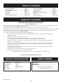 2
2
-
 3
3
-
 4
4
-
 5
5
-
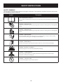 6
6
-
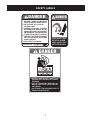 7
7
-
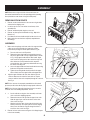 8
8
-
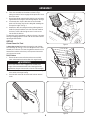 9
9
-
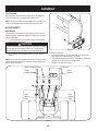 10
10
-
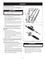 11
11
-
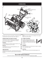 12
12
-
 13
13
-
 14
14
-
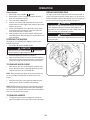 15
15
-
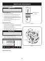 16
16
-
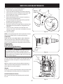 17
17
-
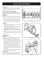 18
18
-
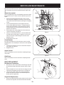 19
19
-
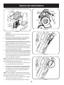 20
20
-
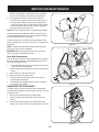 21
21
-
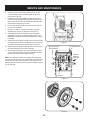 22
22
-
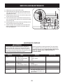 23
23
-
 24
24
-
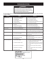 25
25
-
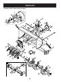 26
26
-
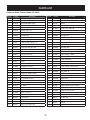 27
27
-
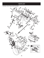 28
28
-
 29
29
-
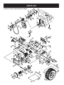 30
30
-
 31
31
-
 32
32
-
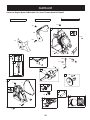 33
33
-
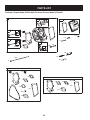 34
34
-
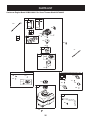 35
35
-
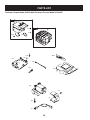 36
36
-
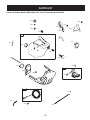 37
37
-
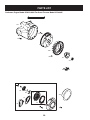 38
38
-
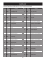 39
39
-
 40
40
-
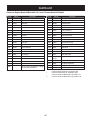 41
41
-
 42
42
-
 43
43
-
 44
44
-
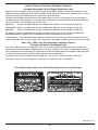 45
45
-
 46
46
-
 47
47
-
 48
48
-
 49
49
-
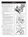 50
50
-
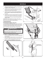 51
51
-
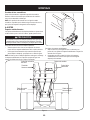 52
52
-
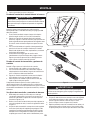 53
53
-
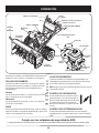 54
54
-
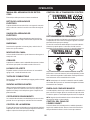 55
55
-
 56
56
-
 57
57
-
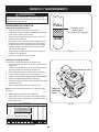 58
58
-
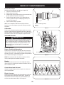 59
59
-
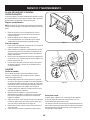 60
60
-
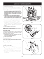 61
61
-
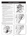 62
62
-
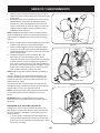 63
63
-
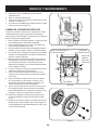 64
64
-
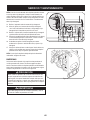 65
65
-
 66
66
-
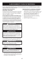 67
67
-
 68
68
-
 69
69
-
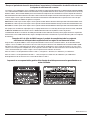 70
70
-
 71
71
-
 72
72


Craftsman 247.88845 Manual de usuario
- Categoría
- Lanzadores de nieve
- Tipo
- Manual de usuario
- Este manual también es adecuado para
en otros idiomas
- English: Craftsman 247.88845 User manual
Artículos relacionados
-
Craftsman 247.881900 Manual de usuario
-
-
-
MTD 247883962 El manual del propietario
-
-
-
-
-
-
Otros documentos
-
Sears Snow Blower 247.88355 Manual de usuario
-
Troy-Bilt 31BM73Q3766 Manual de usuario
-
MTD E285 Manual de usuario
-
-
Troy-Bilt 31AH97P7711 Manual de usuario
-
-
-
-
-