Troy-Bilt 31BM73Q3766 Manual de usuario
- Categoría
- Lanzadores de nieve
- Tipo
- Manual de usuario
Este manual también es adecuado para

TROY-BILT LLC, P.O. BOX 361131 CLEVELAND, OHIO 44136-0019
Printed In USA
Op e r a t O r ’s Ma n u a l
Safe Operation Practices • Set-Up • Operation • Maintenance • Service • Troubleshooting • Warranty
WARNING
READ AND FOLLOW ALL SAFETY RULES AND INSTRUCTIONS IN THIS MANUAL
BEFORE ATTEMPTING TO OPERATE THIS MACHINE.
FAILURE TO COMPLY WITH THESE INSTRUCTIONS MAY RESULT IN PERSONAL INJURY.
Snow Tracker 2690
Form No. 769-05188A
(July 31, 2009)

Customer Support
Please do NOT return the machine to the retailer or dealer without first contacting our Customer Support Department.
If you have difficulty assembling this product or have any questions regarding the controls, operation, or maintenance of
this machine, you can seek help from the experts. Choose from the options below:
Visit us on the web at www.troybilt.com◊
Call a Customer Support Representative at (800) 828-5500 or (330) 558-7220◊
◊
Thank you for purchasing a Snow Thrower manufactured by
Troy-Bilt LLC. It was carefully engineered to provide excellent
performance when properly operated and maintained.
It instructs you how to safely and easily set up, operate and
persons who will operate the machine, carefully follow the
recommended safety practices at all times. Failure to do so could
result in personal injury or property damage.
All information in this manual is relative to the most recent
product information available at the time of printing. Review
this manual frequently to familiarize yourself with the machine,
Manual may cover a range of product specifications for various
models. Characteristics and features discussed and/or illustrated
in this manual may not be applicable to all models. Troy-Bilt LLC
reserves the right to change product specifications, designs and
equipment without notice and without incurring obligation.
If you have any problems or questions concerning the machine,
phone a authorized Troy-Bilt service dealer or contact us directly.
address and mailing address can be found on this page. We want
to ensure your complete satisfaction at all times.
Throughout this manual, all references to right and left side of the
machine are observed from the operating position.
Thank You
Record Product Information
Before setting up and operating your new equipment, please
locate the model plate on the equipment and record the
information in the provided area to the right. You can locate the
down at the rear of the frame. This information will be necessary,
should you seek technical support via our web site, Customer
Support Department, or with a local authorized service dealer.
MO d e l nu M b e r
se r i a l nu M b e r
To The Owner
1
2
Safe Operation Practices ........................................ 3
Assembly & Set-Up .................................................. 7
Controls ...................................................................12
Operation ................................................................15
Maintenance & Adjustment..................................17
Engine Maintenance ............................................. 20
Service .................................................................... 22
Troubleshooting .................................................... 26
Replacement Parts ................................................ 27
Spanish ....................................................................31
Warranty ..................................................Back Cover
Table of Contents

Important Safe Operation Practices
2
3
Training
Read, understand, and follow all instructions on the
machine and in the manual(s) before attempting to
assemble and operate. Keep this manual in a safe place for
future and regular reference and for ordering replacement
parts.
Be familiar with all controls and their proper operation. 2.
Know how to stop the machine and disengage them
quickly.
3.
the instructions and safe operation practices in this manual
and on the machine and be trained and supervised by an
adult.
Never allow adults to operate this machine without proper
instruction.
5.
your snow-throwing pattern to avoid discharge of material
toward roads, bystanders and the like.
Keep bystanders, pets and children at least 75 feet from the
machine while it is in operation. Stop machine if anyone
enters the area.
Exercise caution to avoid slipping or falling, especially 7.
when operating in reverse.
Preparation
Thoroughly inspect the area where the equipment is to be used.
Remove all doormats, newspapers, sleds, boards, wires and other
foreign objects, which could be tripped over or thrown by the
auger/impeller.
Always wear safety glasses or eye shields during operation
and while performing an adjustment or repair to protect
your eyes. Thrown objects which ricochet can cause serious
injury to the eyes.
Do not operate without wearing adequate winter outer 2.
garments. Do not wear jewelry, long scarves or other loose
clothing, which could become entangled in moving parts.
Wear footwear which will improve footing on slippery
surfaces.
Use a grounded three-wire extension cord and receptacle 3.
for all machines with electric start engines.
Adjust collector housing height to clear gravel or crushed
rock surfaces.
Disengage all control levers before starting the engine. 5.
Never attempt to make any adjustments while engine is
running, except where specifically recommended in the
Let engine and machine adjust to outdoor temperature 7.
before starting to clear snow.
WARNING! This symbol points out important safety instructions which, if not followed,
could endanger the personal safety and/or property of yourself and others. Read and follow
all instructions in this manual before attempting to operate this machine. Failure to comply
with these instructions may result in personal injury.
When you see this symbol. HEED ITS WARNING!
DANGER: This machine was built to be operated according to the safe operation practices in
this manual. As with any type of power equipment, carelessness or error on the part of the
operator can result in serious injury. This machine is capable of amputating fingers, hands,
toes and feet and throwing foreign objects. Failure to observe the following safety
instructions could result in serious injury or death.
CALIfORNIA PROPOSITION 65
WARNING! Engine Exhaust, some of its constituents, and certain vehicle components
contain or emit chemicals known to State of California to cause cancer and birth defects
or other reproductive harm.

4 se c t i O n 2 — iM p O r t a n t sa f e Op e r a t i O n pr a c t i c e s
Safe Handling of Gasoline
To avoid personal injury or property damage use extreme care
in handling gasoline. Gasoline is extremely flammable and the
vapors are explosive. Serious personal injury can occur when
gasoline is spilled on yourself or your clothes which can ignite.
Wash your skin and change clothes immediately.
Use only an approved gasoline container.a.
Extinguish all cigarettes, cigars, pipes and other b.
sources of ignition.
Never fuel machine indoors. c.
Never remove gas cap or add fuel while the engine is d.
hot or running.
Allow engine to cool at least two minutes before e.
refueling.
Never over fill fuel tank. Fill tank to no more than ½ f.
inch below bottom of filler neck to provide space for
fuel expansion.
Replace gasoline cap and tighten securely.g.
If gasoline is spilled, wipe it off the engine and h.
equipment. Move machine to another area. Wait 5
minutes before starting the engine.
Never store the machine or fuel container inside i.
where there is an open flame, spark or pilot light
(e.g. furnace, water heater, space heater, clothes
dryer etc.).
Allow machine to cool at least 5 minutes before j.
storing.
Never fill containers inside a vehicle or on a truck k.
or trailer bed with a plastic liner. Always place
containers on the ground away from your vehicle
before filling.
If possible, remove gas-powered equipment from l.
the truck or trailer and refuel it on the ground. If this
is not possible, then refuel such equipment on a
trailer with a portable container, rather than from a
gasoline dispenser nozzle.
Keep the nozzle in contact with the rim of the fuel m.
tank or container opening at all times until fueling is
complete. Do not use a nozzle lock-open device.
Operation
Do not put hands or feet near rotating parts, in the auger/
impeller housing or chute assembly. Contact with the
rotating parts can amputate hands and feet.
The auger/impeller control lever is a safety device. Never 2.
bypass its operation. Doing so makes the machine unsafe
and may cause personal injury.
The control levers must operate easily in both directions 3.
and automatically return to the disengaged position when
released.
Never operate with a missing or damaged chute assembly.
Keep all safety devices in place and working.
Never run an engine indoors or in a poorly ventilated area. 5.
Engine exhaust contains carbon monoxide, an odorless
and deadly gas.
Do not operate machine while under the influence of
alcohol or drugs.
Muffler and engine become hot and can cause a burn. Do 7.
not touch. Keep children away.
Exercise extreme caution when operating on or crossing 8.
gravel surfaces. Stay alert for hidden hazards or traffic.
Exercise caution when changing direction and while
operating on slopes.
towards windows, walls, cars etc. Thus, avoiding possible
property damage or personal injury caused by a ricochet.
Never direct discharge at children, bystanders and pets or
allow anyone in front of the machine.
Do not overload machine capacity by attempting to clear
snow at too fast of a rate.
Never operate this machine without good visibility or light.
Always be sure of your footing and keep a firm hold on the
handles. Walk, never run.
Disengage power to the auger/impeller when transporting
or not in use.
Never operate machine at high transport speeds on
slippery surfaces. Look down and behind and use care
when backing up.
If the machine should start to vibrate abnormally, stop
the engine, disconnect the spark plug wire and ground it
against the engine. Inspect thoroughly for damage. Repair
any damage before starting and operating.
Disengage all control levers and stop engine before you
leave the operating position (behind the handles). Wait
until the auger/impeller comes to a complete stop before
unclogging the chute assembly, making any adjustments,
or inspections.
Never put your hand in the discharge or collector openings.
Always use the clean-out tool provided to unclog the
discharge opening. Do not unclog chute assembly while
engine is running. Shut off engine and remain behind
handles until all moving parts have stopped before
unclogging.
Use only attachments and accessories approved by the
manufacturer (e.g. wheel weights, tire chains, cabs etc.).
When starting engine, pull cord slowly until resistance 20.
is felt, then pull rapidly. Rapid retraction of starter cord
(kickback) will pull hand and arm toward engine faster than
you can let go. Broken bones, fractures, bruises or sprains
could result.
If situations occur which are not covered in this manual, use
care and good judgment. Contact Customer Support for
assistance and the name of your nearest servicing dealer.

5se c t i O n 2 — iM p O r t a n t sa f e Op e r a t i O n pr a c t i c e s
Clearing a Clogged Discharge Chute
chute is the most common cause of injury associated with snow
throwers. Never use your hand to clean out the discharge chute.
To clear the chute:
2.
stopped rotating.
Always use a clean-out tool, not your hands.3.
Maintenance & Storage
Never tamper with safety devices. Check their proper
operation regularly. Refer to the maintenance and
adjustment sections of this manual.
Before cleaning, repairing, or inspecting machine 2.
disengage all control levers and stop the engine. Wait until
the auger/impeller come to a complete stop. Disconnect
the spark plug wire and ground against the engine to
prevent unintended starting.
Check bolts and screws for proper tightness at frequent 3.
intervals to keep the machine in safe working condition.
Also, visually inspect machine for any damage.
Do not change the engine governor setting or over-speed
the engine. The governor controls the maximum safe
operating speed of the engine.
Snow thrower shave plates and skid shoes are subject to 5.
wear and damage. For your safety protection, frequently
check all components and replace with original equipment
not meet the original equipment specifications may lead to
Check control levers periodically to verify they engage
and disengage properly and adjust, if necessary. Refer
instructions.
Maintain or replace safety and instruction labels, as 7.
necessary.
8.
etc. to protect the environment.
from machine and prevent freeze up of auger/impeller.
Never store the machine or fuel container inside where
there is an open flame, spark or pilot light such as a water
heater, furnace, clothes dryer etc.
instructions on off-season storage.
Check fuel line, tank, cap, and fittings frequently for cracks
or leaks. Replace if necessary.
Do not crank engine with spark plug removed.
this product has an Average Useful Life of seven (7) years,
Average Useful
Life have the machine inspected annually by an authorized
service dealer to ensure that all mechanical and safety
systems are working properly and not worn excessively.
Failure to do so can result in accidents, injuries or death.
Do not modify engine
To avoid serious injury or death, do not modify engine in any
way. Tampering with the governor setting can lead to a runaway
engine and cause it to operate at unsafe speeds. Never tamper
with factory setting of engine governor.
Notice Regarding Emissions
Engines which are certified to comply with California and federal
are certified to operate on regular unleaded gasoline, and
may include the following emission control systems: Engine
Injection (SAI) and Three Way Catalyst (TWC) if so equipped.
Spark Arrestor
WARNING! This machine is equipped with an
internal combustion engine and should not be used
on or near any unimproved forest-covered, brush
exhaust system is equipped with a spark arrester
meeting applicable local or state laws (if any).
If a spark arrester is used, it should be maintained in effective
working order by the operator. In the State of California the
apply on federal lands.
A spark arrester for the muffler is available through your
nearest engine authorized service dealer or contact the service

6 se c t i O n 2 — iM p O r t a n t sa f e Op e r a t i O n pr a c t i c e s
Safety Symbols
This page depicts and describes safety symbols that may appear on this product. Read, understand, and follow all instructions on the
machine before attempting to assemble and operate.
Symbol Description
Read, understand, and follow all instructions in the manual(s) before attempting to
assemble and operate
Keep hands out of inlet and discharge openings while machine is running. There are rotating
blades inside
Keep hands out of inlet and discharge openings while machine is running. There are rotating
blades inside
Do not put hands or feet near rotating parts, in the auger/impeller housing or chute
assembly. Contact with the rotating parts can amputate hands and feet.
This machine may pick up and throw objects which can cause serious personal injury.
Allow the engine to cool at least two minutes before refueling.
Never run an engine indoors or in a poorly ventilated area. Engine exhaust contains carbon
monoxide, an odorless and deadly gas.
Engine parts, especially the muffler, become extremely hot during operation. Allow engine
and muffler to cool before touching.
WARNING! Your Responsibility—Restrict the use of this power machine to persons who read, understand and
follow the warnings and instructions in this manual and on the machine.
SAVE THESE INSTRUCTIONS!

Assembly
Handle
Remove the lower plastic wing nut and carriage bolt from 2.
each side of the upper handle; then raise the upper handle
assembly until it snaps over the lower handle. Make certain
the upper ends of each cable are seated properly in the
Looking beneath the handle panel, check that all of the 3.
cables (steering, auger, shift, and drive) are properly routed
and not pinched or kinked.
Secure the handle by tightening the plastic knob located
on both the left and right sides of the handle. Remove
and discard any rubber bands, if present. They are for
packaging purposes only.
Chute Assembly
Remove cotter pin, wing nut and hex screw from chute
control head and clevis pin and bow-tie cotter pin from
chute support bracket. See Fig. 3-2.
2.
chute control head as possible, keeping the holes in the
hex rod pointing upward. See Fig. 3-3.
Contents of Crate
Two Ignition Keys
Manual
Figure 3-1
Chute Control Head
Chute
Chute Support
Bracket
Chute Base
Figure 3-2
Figure 3-3
Assembly & Set-Up
3
7

Place chute onto chute base and ensure hex rod is 3.
positioned under the handle panel. Install hex bolt
previously removed but do not secure with wind nut at this
time. See Fig. 3-4.
Squeeze the trigger on the joystick and rotate the chute by 4.
hand to face forward. The holes in the chute control input
will be facing up. See Fig. 3-5.
Note: The chute will not rotate without squeezing the
trigger on the joystick.
Rotate the joystick to the one o’clock position so that the 5.
silver indicator arrow on the pinion gear below the control
panel faces upward. See Fig. 3-6.
Note: The joystick will be angled slightly to the right.
Insert the hex rod into the pinion gear below the joystick. 6.
Make sure to line up the hole in the hex rod with the arrow
on the pinion gear. See Fig. 3-7.
Note: The hex rod will fit snuggly into the pinion gear.
Support the rear of the dash panel with one hand while
inserting the hex rod with your other hand to ensure the
hex rod is inserted all the way into the pinion gear.
Note: The hole is a reference for aligning the rod with the
indicator arrow on the pinion gear.
Figure 3-4
Top View
Chute Control
Input
Figure 3-5
Figure 3-6
Figure 3-7
8 Se c t i o n 2— AS S e m b l y & Se t -Up

Set-Up
Shear Pins
A pair of replacement auger shear pins and bow tie cotter pins
are included with your snow thrower in the manual bag. Store
Chute Clean-Out Tool
The chute clean-out tool is fastened to the top of the auger
housing with a mounting clip and a cable tie at the factory. Cut
Figure 3-10
7.
in the hex rod lines up with the hole in the chute control
input closest to the chute control head and insert the
cotter pin. See Fig. 3-8.
Note: The second hole is used to achieve further
engagement of the hex rod into the pinion gear if required.
Finish securing chute control head to chute support 8.
bracket with wing nut, clevis pin, and bow-tie cotter pin
Check that all cables are properly routed through the cable
Note: For smoothest operation, the cables should all be to
the left of the hex rod.
Chute Clean-Out Tool
Figure 3-11
Figure 3-8
Figure 3-9
9se c t i O n 2 — as s e M b l y & se t -up

Fuel Recommendations
Use automotive gasoline (unleaded or low leaded to minimize
combustion chamber deposits) with a minimum of 87 octane.
Butyl Ether) can be used. Never use an oil/gasoline mixture or
dirty gasoline. Avoid getting dirt, dust, or water in the fuel tank.
Refuel in a well-ventilated area with the engine stopped.
Do not smoke or allow flames or sparks in the area where
the engine is refueled or where gasoline is stored.
Do not overfill the fuel tank. After refueling, make sure the
tank cap is closed properly and securely.
Be careful not to spill fuel when refueling. Spilled fuel or
fuel vapor may ignite. If any fuel is spilled, make sure the
area is dry before starting the engine.
Avoid repeated or prolonged contact with skin or
breathing of vapor.
Adding Fuel
WARNING! Use extreme care when handling
gasoline. Gasoline is extremely flammable and the
vapors are explosive. Never fuel the machine
indoors or while the engine is hot or running.
Extinguish cigarettes, cigars, pipes and other
sources of ignition.
WARNING! Always keep hands and feet clear of
pressurized starting fluid. Vapors are flammable.
Clean around the fuel fill before removing the cap to fuel.
A fuel level indicator is located in the fuel tank. Fill the tank 2.
careful not to overfill.
Checking Oil Level
CAUTION: The engine is shipped with oil in the
engine. You must, however, check the oil level prior
to operating the snow thrower. Running the engine
with insufficient oil can cause serious engine
damage and void the engine warranty.
NOTE: Be sure to check the engine on a level surface with the
engine stopped.
Remove the oil filler cap/dipstick and wipe the dipstick
Insert the cap/dipstick into the oil filler neck, but do 2. not screw it
in.
Remove the oil filler cap/dipstick. If the level is low, slowly 3.
the correct oil viscosity and engine oil capacity.
NOTE:
engine smoking, hard starting or spark plug fouling.
Replace and tighten the cap/dipstick firmly before starting
the engine.
Fill
between
high
and low
marks
Figure 3-13
Fuel Level Indicator
Top View
Figure 3-12
10 se c t i O n 2— as s e M b l y & se t -up

Adjustments
Skid Shoes
The snow thrower skid shoes are adjusted upward at the factory
for shipping purposes. Adjust them downward, if desired, prior
to operating the snow thrower.
CAUTION: It is not recommended that you operate
this snow thrower on gravel as it can easily pick up
and throw loose gravel, causing personal injury or
damage to the snow thrower and surrounding
property.
For close snow removal on a smooth surface, raise the skid shoes
higher on the auger housing.
Use a middle or lower position when the area to be cleared is
uneven, such as a gravel driveway
NOTE: If you choose to operate the snow thrower on
a gravel surface, keep the skid shoes in position for
maximum clearance between the ground and the shave
plate.
To adjust the skid shoes:
Loosen the four hex nuts (two on each side) and carriage
bolts. Move the skid shoes to the desired position. See Fig.
Make certain the entire bottom surface of the skid shoe is against 2.
the ground to avoid uneven wear on the skid shoes.
Retighten the nuts and bolts securely.3.
Auger Control
WARNING!
carefully read and follow all the instructions below.
is operating safely and properly.
Check the adjustment of the auger control as follows:
When the auger control is released and in the disengaged
In a well-ventilated area, start the snow thrower engine. 2.
3.
thrower), engage the auger.
Allow the auger to remain engaged for approximately ten
several times.
With the throttle control in the FAST (rabbit) position and 5.
the front of the machine.
Confirm that the auger has completely stopped rotating
IMPORTANT: If the auger shows ANY signs of rotating,
engine. Wait for ALL moving parts to stop before readjusting the
auger control.
To readjust the control cable, loosen the hex jam nut on the 7.
8.
pliers and tighten the jam nut against the ferrule.
Figure 3-14
Figure 3-15
11se c t i O n 2 — as s e M b l y & se t -up

Track Drive Control/Auger
Control Lock
Headlight
Chute Assembly
Chute
Cleanout
Tool
Auger
Skid Shoe
Shift Lever
Chute Directional Control
Auger Control
Track Steering Control
Heated Grips
Track Lock Lever
Normal Snow
Packed Snow
Transport
Ignition Key
Oil Fill
Primer
Gasoline
Cap
Electric
Starter
Outlet
Recoil Starter
Handle
Oil Drain
Choke
Control
Throttle
Control
Electric
Starter
Button
Figure 4-1
WARNING! Read, understand, and follow all
instructions and warnings on the machine and in
this manual before operating.
Shift Lever
The shift lever is located in the right side of the handle panel and
is used to determine both the ground speed and direction of
travel. It can be moved into any of eight positions.
Forward
Your snow thrower has six forward (F) speeds, with position
Reverse
Your snow thrower has two reverse (R) speeds, with position
NOTE: Always release the drive control before changing
speeds.
Headlight
The headlight is on whenever the engine is running.
Heated Grip
To activate the heated grips, move the switch found on the rear
Skid Shoe
The space between the shave plate and the ground can be
adjusted by positioning the skid shoes. Refer to Skid Shoe
Controls and Features
4
12

Track Drive Control / Auger Clutch Lock*
The track drive control is located on the right handle. Squeeze
the control grip against the handle to engage the track drive.
Release to stop.
Note: Always release the drive control before changing speeds.
drive system.
so that you can operate the chute control handle without
interrupting the snow throwing process. If the auger control is
engaged simultaneously with the drive control, the operator can
release the auger control (on the left handle) and the augers will
remain engaged. Release both controls to stop the augers and
the track drive.
Auger Control
The auger control is located on the left handle. Squeeze the
control grip against the handle to engage the augers and start
snow throwing action. Release to stop.
Augers
When engaged, the augers rotate and draw snow into the auger
housing.
Chute Assembly
Snow drawn into the auger housing is discharged out the chute
assembly.
Recoil Starter Handle
This handle is used to manually start the engine.
Track Steering Controls
The left and right track steering controls are located on the
underside of the handles and they are used to assist in steering
the snow thrower. Squeeze the right track control when turning
snow thrower in open areas until you become familiar with these
controls.
NOTE: It is easier to maneuver a non-running snow thrower
with both track steering controls held in simultaneously.
Chute Directional Control
The chute directional control is located on the left side of the
dash panel.
To change the direction in which snow is thrown, squeeze
the button on the joy-stick and pivot the joy-stick to the
right or to the left.
To change the angle/distance which snow is thrown, pivot
the joy-stick forward or backward.
Track Lock Lever
The track lock lever is located on the right side of the snow
thrower and is used to select the position of the auger housing
and the method of track operation. Move the lever to the right,
then forward or backward to one of the three positions.
Transport
Raises the front end of the snow thrower for easy transport.
Using proper caution, this position may also be used on many
gravel driveways to clear snow while leaving gravel undisturbed.
13se c t i O n 4 — cO n t r O l s a n d fe a t u r e s

Normal Snow
Allows the tracks to be suspended independently for continuous
ground contact.
Packed Snow
Locks the front end of the snow thrower down to the ground for
hard-packed or icy snow conditions.
Oil Fill
Engine oil level can be checked and oil added through the oil fill.
Oil Drain
Engine oil can be drained through the oil drain.
Muffler
Engine exhaust exists the engine via the muffler.
WARNING! Do not touch the muffler while the
engine is hot or running. The muffler is hot and can
cause a severe burn.
Electric Starter Outlet
Requires the use of a three-prong outdoor extension cord and a
NOTE: The electric starter is mounted to the plastic shroud and is
Electric Starter Button
Gas Cap
Un-thread the gas cap to add gasoline to the fuel tank.
Primer
Throttle Control
The throttle control is located on the engine. It regulates the
speed of the engine and will shut off the engine when pushed
into the stop position.
Choke Control
The choke control is found on the rear of
the engine and is activated by rotating the
knob clockwise. Activating the choke control
closes the choke plate on the carburetor and
aids in starting the engine.
RUN
MAR
V
DÉ RT
Key
The key must be fully inserted and snapped
in place before the engine will start. Remove
the key to prevent any unauthorized use of the
equipment.
NOTE:
Chute Clean-Out Tool
WARNING! Never use your hands to clear a
clogged chute assembly. Shut off engine and remain
behind handles until all moving parts have stopped
before unclogging.
The chute clean-out tool is conveniently fastened to the rear of
the auger housing with a mounting clip. Should snow and ice
become lodged in the chute assembly during operation, proceed
as follows to safely clean the chute assembly and chute opening:
Release both the Auger Control and the Drive Control.
Stop the engine by removing the ignition key.2.
Remove the clean-out tool from the clip which secures it to 3.
the rear of the auger housing.
Use the shovel-shaped end of the clean-out tool to
dislodge and scoop any snow and ice which has formed in
and near the chute assembly.
Refasten the clean-out tool to the mounting clip on the 5.
rear of the auger housing, reinsert the ignition key and
thrower), engage the auger control for a few seconds to clear any
remaining snow and ice from the chute assembly.
14 se c t i O n 4— cO n t r O l s a n d fe a t u r e s

Starting the Engine
WARNING! Always keep hands and feet clear of
moving parts. Do not use a pressurized starting
fluid. Vapors are flammable.
NOTE: Allow the engine to warm up for a few minutes after
starting. The engine will not develop full power until it reaches
operating temperatures.
Electric Starter
WARNING! The electric starter is equipped with a
grounded three-wire power cord and plug, and is
current. It must be used with a properly grounded
three-prong receptacle at all times to avoid the
possibility of electric shock. Follow all instructions
carefully prior to operating the electric starter.
grounded system. Ask a licensed electrician if you are
unsure. If you have a grounded three-prong receptacle,
proceed as follows. If you do not have the proper house
conditions.
2.
unless the key is inserted into the ignition switch.
3.
ventilated area. See Fig. 5-2.
Move the throttle control to the FAST (rabbit) position.
5.
engine is warm, place the choke in the RUN position.
the vent hole when pushing. If the engine is warm, push
the primer only once. Always cover the vent hole when
pushing. Cool weather may require priming to be repeated.
7.
engine starts, immediately release the starter button.
The electric starter is equipped with thermal overload
protection; the system will temporarily shut-down to
allow the starter to cool if the electric starter becomes
overloaded.
As the engine warms, slowly rotate the choke control to 8.
the RUN position. If the engine falters, restart the engine
and run with the choke at half-choke position for a short
period of time, and then slowly rotate the choke into the
RUN position.
After the engine is running, disconnect the power cord
from the electric starter. When disconnecting, always
unplug the end at the wall outlet before unplugging the
opposite end from the engine.
Figure 5-1
Figure 5-2
Operation
5
15

Recoil Starter
CAUTION! Do not pull the starter handle while the
engine running.
WARNING! To avoid unsupervised engine
operation, never leave the engine unattended while
running. Turn the engine off after use and remove
the key
unless the key is inserted into the ignition switch.
Move the throttle control to the FAST (rabbit) position.2.
3.
If the engine is warm, place the choke in the RUN position.
the vent hole when pushing. If the engine is warm, push
the primer only once. Always cover the vent hole when
pushing. Cool weather may require priming to be repeated.
5.
resist, then pull quickly and forcefully to overcome the
compression. Do not release the handle and allow it to
If required, repeat this step.
WARNING! Rapid retraction of the starter cord
(kickback) will pull your hand and arm toward
engine faster than you can let go. Broken bones,
fractures, bruises or sprains could result.
As the engine warms, slowly rotate the choke control to the
RUN position. If the engine falters, restart the engine and
run with the choke at the half-choke position for a short
period of time, and then slowly rotate the choke into RUN
position.
Stopping the Engine
WARNING! To avoid unsupervised engine
operation, never leave the machine unattended
with the engine running. Turn the engine off after
use and remove the key
Run the engine for a few minutes before stopping to help dry off
any moisture on the engine.
Remove the key. Removing the key will reduce the 2.
possibility of any unauthorized starting of the engine while
the equipment is not in use. Keep the key in a safe place.
The engine cannot start without the key.
Wipe any moisture away from the controls on the engine.3.
To Engage Drive
With the throttle control in the Fast (rabbit) position, move
the shift lever into one of the six forward (F) positions or
two reverse (R) positions. Select a speed appropriate for
the snow conditions and a pace you are comfortable with.
Squeeze the drive control against the handle and the snow 2.
thrower will move. Release it and the drive motion will
stop.
To Engage Augers
To engage the augers and start throwing snow, squeeze
the auger control against the left handle. Release to stop
the augers.
16 se c t i O n 5— Op e r a t i O n

Maintenance
Engine
Refer to the Engine Maintenance section.
Shave Plate and Skid Shoes
The shave plate and skid shoes on the bottom of the snow
thrower are subject to wear. They should be checked periodically
and replaced when necessary.
To remove the skid shoes:
Remove the four carriage bolts and hex flange nuts which
secure them to the snow thrower.
Reassemble the new skid shoes with the four carriage bolts 2.
To remove the shave plate:
Remove the carriage bolts and hex nuts which attach it to the
snow thrower housing.
Reassemble new shave plate, making sure heads of 2.
carriage bolts are to the inside of housing. Tighten securely.
Lubrication
Gear Shaft
The gear (hex) shaft should be lubricated at least once a season
or after every twenty-five (25) hours of operation.
Run fuel tank dry, then carefully pivot the snow thrower up
and forward so that it rests on the auger housing.
Remove the frame cover from the underside of the snow 2.
thrower by removing the four self-tapping screws which
3.
NOTE: Augers not shown for clarity.
Figure 6-1
Self-Tapping Screws
Figure 6-2
Gear (Hex) Shaft
Friction Wheel
Figure 6-3
Maintenance & Adjustments
6
17

NOTE: When lubricating the hex shaft, be careful not to get
any oil on the aluminum drive plate or the rubber friction
system. Wipe off any excess or spilled oil.
Auger Shaft
At least once a season, remove the shear pins from the auger
shaft. Spray lubricant inside the shaft and around the spacers and
the flange bearings found at either end of the shaft.
Adjustments
Shift Cable
If the full range of speeds (forward and reverse) cannot be
achieved adjust the shift cable as follows:
Loosen the hex nut on the shift cable index bracket. See 2.
3.
Retighten the hex nut.
Auger Control
Refer to the Assembly and Set-up section for instructions on
adjusting the auger control cable.
Skid Shoes
Refer to the Assembly and Set-up section for instructions on
adjusting the skid shoes.
Track Tension
the flange lock nut on the front of the track side plate. This pulls
Shear Pin
Bow-Tie Cotter Pin
Figure 6-4
Figure 6-5
“J” Bolt
Flange Lock Nut
Track Side Plate
Figure 6-6
18 se c t i O n 6— Ma i n t e n a n c e & ad j u s t M e n t s

Drive Control
tight.
NOTE: If excessive slack is present in the drive cable or if the snow
the cable may be in need of adjustment.
Check the adjustment of the drive control as follows:
With the drive control released, push the snow thrower
gently forward. The unit should roll freely.
Engage the drive control and gently attempt to push the 2.
snow thrower forward. The wheels should not turn. The
unit should not roll freely.
With the drive control released, move the shift lever back 3.
several times. There should be no resistance in the shift
lever.
If any of the above tests failed, the drive cable is in need of
To readjust the drive, loosen the hex jam nut on the auger 5.
pliers and tighten the jam nut against the ferrule.
Rotate the coupling end of the cable counterclockwise to 7.
provide more slack.
8.
Repeat Auger Control Test to verify proper adjustment has been
achieved.
Chute Directional Control
To adjust the chute control rod, proceed as follows:
Remove the cotter pin from the hole closest to the chute
assembly on the chute rotation assembly.
2.
with the second hole in the chute rotation assembly. See
Reinsert the cotter pin through this hole and the chute 3.
Off-Season Storage
If the snow thrower will not be used for 30 days or longer, follow
the storage instructions below.
Lubricate the machine as instructed earlier in this section.
Store in a clean, dry area.2.
If storing the snow thrower in an unventilated area, 3.
rustproof the machine using a light oil or silicone to coat
the snow thrower.
Clean the exterior of the engine and the snow thrower.
NOTE: Refer to the Engine Maintenance section for information
on storing your engine.
Figure 6-7
Figure 6-8
19se c t i O n 6 — Ma i n t e n a n c e & ad j u s t M e n t s

WARNING! To prevent accidental start-up, shut off
the engine and remove the key before performing
any type of engine maintenance.
high level performance is to be maintained. Regular maintenance
will also ensure a long service life. The required service intervals
and the type of maintenance to be performed are described
in the table below. Follow the hourly or calendar intervals,
whichever occur first. More frequent service is required when
operating in adverse conditions.
Maintenance Schedule
Changing Engine Oil
NOTE: Check the oil level before each use and after every five
hours of operation to be sure correct oil level is maintained. Refer
Drain fuel from tank by running engine until the fuel tank is
empty. Be sure fuel fill cap is secure.
2.
3.
Tip engine to drain oil into the container. Used oil must be
disposed of at a proper collection center.
Reinstall the drain plug and washer and tighten securely. 5.
Oil Drain
Oil Plug
Figure 7-1
Refill with the recommended oil and check the oil level;
Reinstall the oil filler cap/dipstick securely.7.
CAUTION: Thoroughly wash your hands with soap
and water as soon as possible after handling
used oil.
NOTE:
friendly to the environment. Take it to a recycling center or other
collection center.
Oil Recommendations
When adding oil to the engine, refer to viscosity chart below.
quality motor oil certified to meet or exceed U.S. automobile
Motor oils classified SG, SF will show this designation on the
container.
-30º -20º -10º 0º
0º 20º 40º-20º
5W-30
0W-30
-40º
Synthetic
CAUTION:
service life.
TasksF.Each Use or
Evers.
Every Season
Every Season
or 5s.
Every Season
00rs.
Service Dates
Check engine oil
Change engine oil
Check spark plug
Service spark plug
Clean exhaust area
Engine Maintenance
7
20

Check that the spark plug washer is in good condition
and thread the spark plug in by hand to prevent cross-
threading.
After the spark plug is seated, tighten with a spark plug 5.
wrench to compress the washer.
NOTE: When installing a new spark plug, tighten ⁄-turn
after the spark plug seats to compress the washer. When
reinstalling a used spark plug, tighten ⁄- to ⁄-turn after
the spark plug seats to compress the washer.
CAUTION! The spark plug must be tightened
securely. A loose spark plug can become very hot
and can damage the engine.
Cleaning the Engine
If the engine has been running, allow it to cool for at least half
engine.
CAUTION! Do not spray engine with water to clean
because water could contaminate fuel. Using a
garden hose or pressure washing equipment can
also force water into the muffler opening. Water that
passes through the muffler can enter the cylinder,
causing damage.
WARNING! Accumulation of debris around muffler
could cause a fire. Inspect and clean before every
use.
Off-Season Storage
Engines stored over 30 days need to be drained of fuel to
prevent deterioration and gum from forming in the fuel
system or on essential carburetor parts. If the gasoline in your
engine deteriorates during storage, you may need to have the
carburetor, and other fuel system components, serviced or
replaced.
Remove all fuel from tank by running engine until it stops.
Change the engine oil.
several times to distribute the oil, and reinstall the spark
plug.
Clean debris from around engine, and under, around, and
behind muffler. Apply a light film of oil on any areas that
are susceptible to rust.
Store in a clean, dry and well ventilated area away from any
appliance that operates with a flame or pilot light, such as a
furnace, water heater, or clothes dryer. Avoid any area with
a spark producing electric motor, or where power tools are
operated.
If possible, avoid storage areas with high humidity.
Keep the engine level in storage. Tilting can cause fuel or
oil leakage.
Spark Plug
WARNING!
plug removed.
WARNING! If the engine has been running, the
muffler will be very hot. Be careful not to touch the
muffler.
To ensure proper engine operation, the spark plug must be
properly gapped and free of deposits.
Remove the spark plug boot and use a spark plug wrench
to remove the plug. See Fig. 7-2.
Visually inspect the spark plug. Discard the spark plug 2.
if there is apparent wear, or if the insulator is cracked or
chipped. Clean the spark plug with a wire brush if it is to be
reused.
Measure the plug gap with a feeler gauge. Correct as 3.
necessary by bending side electrode. See Fig. 7-3. The gap
Spark Plug
Spark Plug Boot
Figure 7-2
Figure 7-3
.02-.03 in.
(0.60-0.80 mm)
Electrode
21se c t i O n 7 — en g i n e Ma i n t e n a n c e

Belt Replacement
Auger Belt
NOTE: It is not necessary to remove both belts in order to change
either one. If changing just one belt, be certain to check the
condition of the other belt.
Drain the gasoline from the snow thrower, or place a piece
of plastic film under the gas cap.
Remove the plastic belt cover at the front of the engine by 2.
Tip the snow thrower up and forward so that it rests on its 3.
auger housing.
Remove the frame cover from the underside of the snow
thrower by removing the self-tapping screws which secure
it. See Fig. 7-2.
Roll the auger belt off the engine pulley. See Fig. 7-3.5.
Self-Tapping Screws
Figure 7-3
Figure 7-1
Figure 7-2
Service
8
22

Unhook the idler spring from the hex bolt on the auger
Lift the auger belt from the auger pulley, and slip belt 7.
between the support bracket and the auger pulley. See Fig.
7-5.
Replace auger drive belt by following instructions in 8.
reverse order.
Drive Belt
as follows:
Drain the gasoline from the snow thrower or run the fuel
tank dry.
Remove the plastic belt cover on the front of the engine by 2.
Carefully pivot the snow thrower up and forward so that it 3.
rests on the auger housing.
Remove the frame cover from the underside of the snow
thrower by removing self-tapping screws which secure it.
Ref. Fig. 7-2.
To remove the belt from the pulleys proceed as follows:5.
Use a wrench to pivot the idler pulley toward the a.
Roll the auger belt off the engine pulley.b.
Lift the drive belt off engine pulley.c.
Back out the stop bolt until the support bracket rests on
A
B
C
Figure 7-6
Auger Belt
Auger Pulley
Figure 7-5
Idler Spring
Hex Bolt
Stop Bolt
Figure 7-4
23se c t i O n 8 — se r v i c e

Slip the drive belt off the pulley and between friction
wheel and drive pulley. See Fig. 7-7.
Remove and replace belt in the reverse order.7.
NOTE: Engaging the drive control will ease re-assembly of
the belt.
Friction Wheel Removal
The rubber on the friction wheel is subject to wear and should be
checked after 25 hours of operation, and periodically thereafter.
Replace the friction wheel rubber if any signs of wear or cracking
are found.
Drain the gasoline from the snow thrower.
Tip the snow thrower up and forward, so that it rests on the 2.
housing.
Remove the self-tapping screws from the frame cover 3.
underneath the snow thrower.
Using a ⁄
bolt and bell washer on the left end of gear shaft. See Fig.
Move the gear shaft to the right and slide the friction wheel 5.
Drive Pulley
Drive Belt
Figure 7-7
Hex Screw &
Bell Washer
Track
Figure 7-8
Gear Shaft
Friction Wheel
Assembly
Figure 7-9
24 se c t i O n 8— se r v i c e

If replacing the entire assembly, put the new friction
wheel assembly in place and follow the steps in reverse to
re-assemble. If you only want to replace the friction wheel
rubber continue with step 7.
Remove the four screws from the friction wheel assembly. 7.
Remove the friction wheel rubber from between the 8.
friction wheel plates.
Reassemble new friction wheel rubber to the friction wheel
plates and hub, tightening the four screws in rotation and
the shift rod assembly, and slide the shaft through the
Screws
Side Plates
Rubber Ring
Figure 7-11
25se c t i O n 8 — se r v i c e

Troubleshooting
9
26
Problem Cause Remedy
Engine fails to start Fuel tank empty, or stale fuel. 1.
Blocked fuel line.2.
Choke not in the RUN position.3.
Faulty spark plug.4.
Key not in ignition switch on engine.5.
Spark plug wire disconnected.6.
Primer button not being used properly.7.
Fill tank with clean, fresh gasoline. Fuel 1.
becomes stale after thirty days.
Clean the fuel line.2.
Move choke control to RUN position3.
Clean, adjust gap or replace.4.
Insert the key fully into the switch.5.
Connect spark plug wire.6.
Refer to the Operation Section.7.
Engine running erratically/
inconsistent RPM (hunting
or surging)
Engine running on CHOKE.1.
Fuel line blocked or stale fuel. 2.
Water or dirt in fuel system.3.
Carburetor out of adjustment.4.
Over-governed engine.5.
Move choke control to RUN position.1.
Clean fuel line and fill tank with fresh clean, 2.
gasoline.
Run engine until it stops. Refill with fresh fuel.3.
Contact an authorized service center.4.
Contact an authorized service center.5.
Loss of power Spark plug wire loose.1.
Gas cap vent hole plugged.2.
Connect and tighten spark plug wire.1.
Remove ice and snow from gas cap. Be 2.
certain vent hole is clear.
Excessive vibration Loose parts or damaged auger.1. Stop the engine immediately and disconnect 1.
the spark plug wire. Tighten all bolts and
nuts. If vibration continues, have the snow
thrower serviced by an authorized service
dealer.
Snow Thrower fails to
propel itself
Drive control cable in need of adjustment. 1.
Drive belt loose or damaged. 2.
Friction wheel worn.3.
Adjust drive control cable. Refer to 1.
Maintenance & Adjustments Section.
Replace drive belt. Refer to the Service 2.
Section.
Replace the friction wheel.3.
Snow Thrower fails to
discharge snow
Chute assembly clogged. 1.
Shear pin(s) sheared.2.
Foreign object lodged in auger. 3.
Auger control cable in need of adjustment. 4.
Auger belt loose or damaged.5.
Stop engine and disconnect spark plug wire. 1.
Clean chute and inside of auger housing with
clean-out tool or a stick.
Replace shear pin(s).2.
Stop engine immediately and disconnect 3.
spark plug wire. Remove object from auger.
Adjust auger control cable. Refer to the 4.
Maintenance & Adjustments Section.
Refer to Service Section.5.
Chute fails to easily rotate
180 degrees
Chute assembled incorrectly.1. Unassemble chute control and reassemble as 1.
directed in the Assembly section.

Component Part Number and Description
Replacement Parts
10
27
(800) 828-5500

Troy-Bilt LLC (Troy-Bilt), the California Air Resources Board (CARB)
and the United States Environment Protection Agency (U. S. EPA)
Emission Control System Warranty Statement
(Owner’s Defect Warranty Rights and Obligations)
EMISSION CONTROL SYSTEM COVERAGE IS APPLICABLE TO CERTIFIED ENGINES PURCHASED IN CALIFORNIA IN 2005 AND THERE-
AFTER, WHICH ARE USED IN CALIFORNIA, AND TO CERTIFIED MODEL YEAR 2005 AND LATER ENGINES WHICH ARE PURCHASED AND
USED ELSEWHERE IN THE UNITED STATES.
California and elsewhere in the United States Emission Control Defects Warranty Coverage
The California Air Resources Board (CARB), U. S. EPA and Troy-Bilt are pleased to explain the emissions control system warranty on your model
year 2006 and later small off-road engine. In California, new small off-road engines must be designed, built and equipped to meet the States
anti-smog standards. Elsewhere in the United States, new non-road, spark-ignition engines certified for model 2005 and later, must meet similar
standards set forth by the U. S. EPA. Troy-Bilt must warranty the emission control system on your engine for the period of time listed below,
provided there has been no abuse, neglect or improper maintenance of your small off-road engine.
Your emission control system may include parts such as the carburetor, fuel-injection system, the ignition system, and catalytic converter, fuel tanks,
fuel lines, fuel caps, valves, canisters, filters, vapor hoses, clamps, connectors, and other associated emission-related components.
Where a warrantable condition exists, Troy-Bilt will repair your small off-road engine at no cost to your including diagnosis, parts and labor.
MANUFACTURER’S WARRANTY COVERAGE:
This emissions control system is warranted for two years. If any emission-related part on your engine is defective, the part will be repaired or
replaced by Troy-Bilt.
OWNER’S WARRANTY RESPONSIBILITIES:
As the small off-road engine owner, you are responsible for the performance of the required maintenance listed in your Owner’s Manual. Troy-Bilt
recommends that you retain all your receipts covering maintenances on your small off-road engine, but Troy-Bilt can not deny warranty solely for the
lack of receipts or for your failure to ensure the performance to all scheduled maintenance.
As the small off-road engine owner, you should however be aware that Troy-Bilt may deny your warranty coverage if your small off-road engine or
part has failed due to abuse, neglect, improper maintenance or unapproved modifications.
You are responsible for presenting your small off-road engine to an Authorized Troy-Bilt Service Dealer as soon as a problem exists. The warranted
repairs should be completed in a reasonable amount of time, not to exceed 30 days.
If you have any questions regarding your warranty rights and responsibilities, you should contact a Troy-Bilt Service Representative at (866) 840-
6483 and address is Troy-Bilt, LLC, P.O. Box 361131, Cleveland OH, 44136-0019.
DEFECTS WARRANTY REqUIREMENTS FOR 1995 AND LATER SMALL OFF-ROAD ENGINES:
This section applies to 1995 and later small off-road engines. The warranty period begins on the date the engine or equipment is delivered to an
ultimate purchaser.
(a) General Emissions Warranty Coverage
Troy-Bilt must warrant to the ultimate purchaser and each subsequent purchaser that the engine is:
(1) Designed, built, and equipped so as to conform with all applicable regulations adopted by the Air Resources Board pursuant to its authority in
Chapters 1 and 2,Part 5, Division 26 of the Health and Safety Code; and
(2) Free from defects in materials and workmanship that cause the failure of a warranted part to be identical in all material respects to the part as
described in the engine manufacturer’s application for certification for a period of two years.
(b) The warranty on emissions-related parts will be interpreted as follows:
(1) Any warranted part that is not scheduled for replacement as required maintenance in the written instructions required by Subsection (c)
must be warranted for the warranty period defined in Subsection (a)(2). If any such part fails during the period of warranty coverage, it must be
repaired or replaced by Troy-Bilt according to Subsection (4) below. Any such part repaired or replaced under the warranty must be warranted
for the remaining warranty period.
(2) Any warranted part that is scheduled only for regular inspection in the written instructions required by Subsection (c) must be warranted for
the warranty period defined in Subsection (a)(2). A statement in such written instructions to the effect of “repair or replace as necessary” will
not reduce the period of warranty coverage. Any such part repaired or replaced under warranty must be warranted for the remaining warranty
period.
(3) Any warranted part that which is scheduled for replacement as required maintenance in the written instructions required by Subsection (c)
must be warranted for the period of time prior to the first scheduled replacement point for that part. If the part fails prior to the first scheduled
replacement, the part must be repaired or replaced by Troy-Bilt according to Subsection (4) below. Any such part repaired or replaced under
warranty must be warranted for the remainder of the period prior to the first scheduled replacement point for the part.

(4) Repair or replacement of any warranted part under the warranty provisions of this article must be performed at no charge to the owner at a
warranty station.
(5) Notwithstanding the provisions of Subsection (4) above, warranty services or repairs must be provided at all Troy-Bilt distribution centers that
are franchised to service the subject engines.
(6) The owner must not be charged for diagnostic labor that leads to the determination that a warranted part is in fact defective, provided that
such diagnostic work is performed at a warranty station.
(7) The engine manufacturer is liable for damages to other engine components proximately caused by a failure under warranty of any warranted
part.
(8) Throughout the engine’s warranty period defined in Subsection (a)(2), Troy-Bilt will maintain a supply of warranted parts sufficient to meet
the expected demand for such parts.
(9) Any replacement part may be used in the performance of any warranty maintenance or repairs and must be provided without charge to the
owner. Such use will not reduce the warranty obligations of Troy-Bilt.
(10) Add-on or modified parts that are not exempted by the Air Resources Board may not be used. The use of any non-exempted add-on or
modified parts shall be grounds for disallowing a warranty claim made in accordance with this article. The engine manufacturer shall not be
liable under this article to warrant failures of warranted parts caused by the use of non-exempted add-on or modified part.
(c) Troy-Bilt will include a copy of the following emission warranty parts list with each new engine, using those portions of the list applicable to
the engine.
(1) Fuel Metering System
•Coldstartenrichmentsystem(softchoke)
•Carburetorandinternalparts
•FuelPump
•FuelTank
(2) Air Induction System
•Aircleaner
•Intakemanifold
(3) Ignition System
•Sparkplug(s)
•MagnetoIgnitionSystem
(4) Exhaust System
•Catalyticconverter
•SAI(Reedvalve)
(5) Miscellaneous Items Used in Above System
•Vacuum,temperature,position,timesensitivevalvesandswitches
•Connectorsandassemblies
(6) Evaporative control
•FuelHosecertifiedforARBevaporativeemissionof2006.
•FuelHoseClamps
•Tetheredfuelcap
•Carboncanister
•Vaporlines
GDOC-100172 Rev. A

MANUFACTURER’S LIMITED WARRANTY FOR
GDOC-100166 REV. A
The limited warranty set forth below is given by Troy-Bilt LLC with
respect to new merchandise purchased and used in the United States
and/or its territories and possessions, and by MTD Products Limited
with respect to new merchandise purchased and used in Canada and/
or its territories and possessions (either entity respectively, “Troy-
Bilt”).
“Troy-Bilt” warrants this product (excluding its Normal Wear Parts
and Attachments as described below) against defects in material and
workmanship for a period of two (2) years commencing on the date
of original purchase and will, at its option, repair or replace, free of
charge, any part found to be defective in materials or workmanship.
This limited warranty shall only apply if this product has been
operated and maintained in accordance with the Operator’s Manual
furnished with the product, and has not been subject to misuse,
abuse, commercial use, neglect, accident, improper maintenance,
alteration, vandalism, theft, fire, water, or damage because of other
peril or natural disaster. Damage resulting from the installation or use
of any part, accessory or attachment not approved by Troy-Bilt for use
with the product(s) covered by this manual will void your warranty as
to any resulting damage.
Normal Wear Parts are warranted to be free from defects in material
and workmanship for a period of thirty (30) days from the date of
purchase. Normal wear parts include, but are not limited to items
such as: batteries, belts, blades, blade adapters, tines, grass bags,
wheels, rider deck wheels, seats, snow thrower skid shoes, friction
wheels, shave plates, auger spiral rubber and tires.
Attachments — Troy-Bilt warrants attachments for this product
against defects in material and workmanship for a period of one (1)
year, commencing on the date of the attachment’s original purchase
or lease. Attachments include, but are not limited to items such as:
grass collectors and mulch kits.
HOW TO OBTAIN SERVICE: Warranty service is available, WITH
PROOF OF PURCHASE, through your local authorized service dealer.
To locate the dealer in your area:
In the U.S.A.
Check your Yellow Pages, or contact Troy-Bilt LLC at P.O. Box 361131,
Cleveland, Ohio 44136-0019, or call 1-866-840-6483,
1-330-558-7220 or log on to our Web site at www.troybilt.com.
In Canada
Contact MTD Products Limited, Kitchener, ON N2G 4J1, or call 1-800-
668-1238 or log on to our Web site at www.mtdcanada.com.
This limited warranty does not provide coverage in the following
cases:
a. Log splitter pumps, valves, and cylinders have a separate one-
year warranty.
b. Routine maintenance items such as lubricants, filters, blade
sharpening, tune-ups, brake adjustments, clutch adjustments,
deck adjustments, and normal deterioration of the exterior finish
due to use or exposure.
c. Service completed by someone other than an authorized service
dealer.
d. Troy-Bilt does not extend any warranty for products sold or
exported outside of the United States and/or Canada, and their
respective possessions and territories, except those sold through
Troy-Bilt’s authorized channels of export distribution.
e. Replacement parts that are not genuine Troy-Bilt parts.
f. Transportation charges and service calls.
g. Troy-Bilt does not warrant this product for commercial use.
No implied warranty, including any implied warranty of
merchantability of fitness for a particular purpose, applies after
the applicable period of express written warranty above as to the
parts as identified. No other express warranty, whether written or
oral, except as mentioned above, given by any person or entity,
including a dealer or retailer, with respect to any product, shall
bind Troy-Bilt. During the period of the warranty, the exclusive
remedy is repair or replacement of the product as set forth above.
The provisions as set forth in this warranty provide the sole and
exclusive remedy arising from the sale. Troy-Bilt shall not be liable
for incidental or consequential loss or damage including, without
limitation, expenses incurred for substitute or replacement lawn
care services or for rental expenses to temporarily replace a
warranted product.
Some states do not allow the exclusion or limitation of incidental
or consequential damages, or limitations on how long an implied
warranty lasts, so the above exclusions or limitations may not apply
to you.
In no event shall recovery of any kind be greater than the amount of
the purchase price of the product sold. Alteration of safety features of
the product shall void this warranty. You assume the risk and liability
for loss, damage, or injury to you and your property and/or to others
and their property arising out of the misuse or inability to use the
product.
This limited warranty shall not extend to anyone other than the
original purchaser or to the person for whom it was purchased as a
gift.
HOW STATE LAW RELATES TO THIS WARRANTY: This limited
warranty gives you specific legal rights, and you may also have other
rights which vary from state to state.
IMPORTANT: Owner must present Original Proof of Purchase to
obtain warranty coverage.
Troy-Bilt LLC, P.O. BOX 361131 CLEVELAND, OHIO 44136-0019; Phone: 1-866-840-6483, 1-330-558-7220
MTD Canada Limited - KITCHENER, ON N2G 4J1; Phone 1-800-668-1238

TROY-BILT LLC, P.O. BOX 361131 CLEVELAND, OHIO 44136-0019
Impreso en Estados Unidos de América
Ma n u a l d e l O p e r a d O r
Medidas importantes de seguridad • Conguración • Funcionamiento • Mantenimiento • Servicio •
Solución de problemas • Garantía
ADVERTENCIA
LEA Y SIGA TODAS LAS INSTRUCCIONES DE ESTE MANUAL ANTES DE PONER EN
FUNCIONAMIENTO ESTA MÁQUINA.
SI NO RESPETA ESTAS INSTRUCCIONES PUEDE PROVOCAR LESIONES PERSONALES.
Máquina quitanieve de dos etapas — Storm Tracker 2690
Formulario No. 769-05188
(Junio 23, 2009)

Al propietario
1
32
Asistencia al Cliente
Por favor, NO devuelva la unidad al minorista o distribuidor sin ponerse en contacto primero con el Departamento de
Asistencia al Cliente.
En caso de tener problemas para montar este producto o de tener dudas con respecto a los controles, funcionamiento o
mantenimiento del mismo, puede solicitar la ayuda de expertos. Elija entre las opciones que se presentan a continuación:
Visite nuestro sitio web en www.troybilt.com◊
Llame a un representante de Asistencia al Cliente al (800) 828-5500 ó (330) 558-7220◊
◊
Gracias por comprar una máquina quitanieve fabricada por
Troy-Bilt LLC. La misma ha sido diseñada cuidadosamente
para brindar excelente rendimiento si se la opera y mantiene
correctamente.
Le indica cómo configurar, operar y mantener la máquina
cuidadosamente y en todo momento las prácticas de seguridad
recomendadas, y hacérselas seguir a cualquier otra persona que
opere la máquina. En caso de no hacerlo podrían producirse
lesiones personales o daños materiales.
Toda la información contenida en este manual hace referencia
a la más reciente información de producto disponible en el
momento de la impresión. Revise el manual frecuentemente
para familiarizarse con la unidad, sus características y
productos de diferentes modelos. Las características y funciones
incluidas y/o ilustradas en este manual pueden no ser aplicables
a todos los modelos. Troy-Bilt LLC se reserva el derecho de
modificar las especificaciones de los productos, los diseños y el
equipo estándar sin previo aviso y sin generar responsabilidad
un distribuidor de servicio Troy-Bilt autorizado o póngase en
dirección del sitio web y dirección postal de la Asistencia al
Cliente de Troy-Bilt se encuentran en esta página. Queremos
garantizar su entera satisfacción en todo momento.
En este manual, las referencias al lado derecho o izquierdo de la
máquina se observan desde la posición del operador.
Gracias
Importante Medidas importantes de seguridad 33
Ensamblado y Conguración ............................... 37
Controles y Características ................................... 42
Funcionamiento .................................................... 45
Mantenimiento y Ajustes ...................................... 47
Mantenimiento de Motor ..................................... 50
Servicio ................................................................... 52
Solución de Problemas ......................................... 56
Piezas de Reemplazo ............................................ 57
Índice
nú M e r O d e M O d e l O
nú M e r O d e s e r i e
Registro de información de producto
Antes de configurar y operar su equipo nuevo, por favor localice
la placa del modelo en el equipo y registre la información en
colóquese detrás de la unidad en la posición del operador y mire
hacia la parte inferior de la sección trasera del chasis. Si tiene
que solicitar soporte técnico a través de nuestro sitio web, el
Departamento de Asistencia al Cliente, o de un distribuidor de
servicio autorizado local, necesitará esta información.

Medidas importantes de seguridad
2
33
Capacitación
Lea, entienda y cumpla todas las instrucciones incluidas en
la máquina y en los manuales antes de montarla y utilizarla.
Guarde este manual en un lugar seguro para consultas
futuras y periódicas, así como para solicitar repuestos.
Familiarícese con todos los controles y con el uso adecuado 2.
de los mismos. Sepa cómo detener la máquina y desactivar
los controles rápidamente.
3.
deben leer y entender las instrucciones de operación y
normas de seguridad contenidas en este manual, y en la
máquina ydeben ser entrenados y supervisados por un
adulto.
Nunca permita que los adultos operen esta máquina sin
recibir antes la instrucción apropiada.
Los objetos arrojados por la máquina pueden producir 5.
arrojando nieve para evitar que la descarga de material se
realice hacia los caminos, los observadores, etc.
Mantenga a los observadores, ayudantes, mascotas y niños
por lo menos a 75 pies de la máquina mientras la misma
está en funcionamiento. Detenga la máquina si alguien se
acerca.
Sea precavido para evitar patinarse o caerse especialmente 7.
cuando opera la máquina en reversa.
Preparativos
Inspeccione minuciosamente el área donde utilizará el equipo.
Saque todos los felpudos, periódicos, trineos, tablas, cables y
otros objetos extraños con los que podría tropezar o que podrían
ser arrojados por la barrena / impulsor.
antiparras de seguridad mientras opera la máquina o
mientras la ajusta o repara. Los objetos arrojados que
rebotan pueden producir lesiones oculares graves.
No opere la máquina sin la vestimenta adecuada para 2.
estar al aire libre en invierno. No utilice alhajas, bufandas
largas u otras prendas sueltas que podrían enredarse en las
partes móviles. Utilice un calzado especial para superficies
resbaladizas.
Use un prolongador y un tomacorriente de tres cables con 3.
conexión a tierra para todas las máquinas con motores de
encendido eléctrico.
Ajuste la altura de la caja del tomacorriente para limpiar la
grava o las superficies con piedras trituradas.
Desengrane todas las palancas de control antes de arrancar 5.
el motor.
¡ADVERTENCIA! La presencia de este símbolo indica que se trata de instrucciones
importantes de seguridad que se deben respetar para evitar poner en peligro su seguridad
personal y/o material y la de otras personas. Lea y siga todas las instrucciones de este manual
antes de poner en funcionamiento esta máquina. Si no respeta estas instrucciones puede
provocar lesiones personales.
Cuando vea este símbolo. ¡TENGA EN CUENTAS LAS ADVERTENCIAS!
PELIGRO: Esta máquina está diseñada para ser utilizada respetando las normas de seguridad
contenidas en este manual. Al igual que con cualquier tipo de equipo motorizado, un
descuido o error por parte del operador puede producir lesiones graves. Esta máquina es
capaz de amputar dedos, manos y pies y de arrojar objetos extraños con gran fuerza. De no
respetar las instrucciones de seguridad siguientes se pueden producir lesiones graves o la
muerte.
PROPOSICIóN 65 DE CALIfORNIA
¡ADVERTENCIA! El escape del motor de este producto, algunos de sus componentes y
algunos componentes del vehículo contienen o liberan sustancias químicas que el estado
de California considera que pueden producir cáncer, defectos de nacimiento u otros
problemas reproductivos.

34 se c t i O n 2 — Me d i d a s i M p O r t a n t e s d e s e g u r i d a d
Nunca intente realizar ajustes mientras el motor está
en marcha excepto en los casos específicamente
recomendados en el manual del operador.
Deje que el motor y la máquina se adapten a la 7.
temperatura exterior antes de comenzar a sacar la nieve.
Manejo seguro de la gasolina
evitar lesiones personales o daños materiales tenga mucho
cuidado cuando trabaje con gasolina. La gasolina es sumamente
inflamable y sus vapores pueden causar explosiones. Si se
derrama gasolina encima o sobre la ropa se puede lesionar
gravemente ya que se puede incendiar. Lávese la piel y cámbiese
de ropa de inmediato.
Ua. tilice sólo los recipientes para gasolina autorizados.
Apague todos los cigarrillos, cigarros, pipas y otras b.
fuentes de combustión.
Nunca cargue combustible en la máquina en un c.
espacio cerrado.
Nunca saque la tapa del combustible ni agregue d.
combustible mientras el motor está caliente o en
marcha.
Deje que el motor se enfríe por lo menos dos e.
minutos antes de volver a cargar combustible.
Nunca llene en exceso el depósito de combustible. f.
Llene el tanque a no más de ½ pulgada por debajo
de la base del cuello de llenado dejando espacio
para la dilatación del combustible.
g.
bien.
Limpie el combustible que se haya derramado sobre h.
el motor y el equipo. Traslade la máquina a otra
zona. Espere 5 minutos antes de encender el motor.
Nunca almacene la máquina o el recipiente de i.
combustible en un espacio cerrado donde haya
fuego, chispas o luz piloto (por ejemplo, hornos,
calentadores de agua, calefactores, secadores de
ropa, etc.).
Deje que la máquina se enfríe por lo menos 5 j.
minutos antes de guardarla.
Nunca llene los recipientes en el interior de k.
un vehículo o camión o caja de remolque con
recubrimientos plásticos. Coloque siempre los
recipientes en el piso y lejos del vehículo antes de
llenarlos.
Si es posible, retire el equipo a gasolina del camión o l.
remolque y llénelo en el suelo. Si esto no es posible,
llene el equipo en un remolque con contenedor
portátil, en vez de desde una boquilla dispensadora
de gasolina.
Mantenga la boquilla dispensadora en contacto m.
con el borde del depósito de combustible o con la
abertura del recipiente en todo momento, hasta
terminar la carga. No utilice un dispositivo de
apertura/cierre de boquilla.
Funcionamiento
No ponga las manos o los pies cerca de las piezas
rotatorias, en la caja de la barrena / impulsor o en el
giratorias puede resultar en la amputación de manos o
pies.
La palanca de control de la barrena / impulsor es un 2.
dispositivo de seguridad. Nunca evite su funcionamiento.
De hacerlo la operación de la máquina es riesgosa y puede
ocasionar lesiones.
Las palancas de control deben funcionar bien en ambas 3.
direcciones y regresar automáticamente a la posición de
desengrane cuando se las suelta.
Nunca opere la máquina si falta un montaje del canal o si
el mismo está dañado. Mantenga todos los dispositivos de
seguridad en su lugar y en funcionamiento.
Nunca encienda el motor en espacios cerrados o en una 5.
zona con poca ventilación. El escape del motor contiene
monóxido de carbono, un gas inodoro y letal.
No utilice la máquina bajo la influencia del alcohol o las
drogas.
El silenciador y el motor se calientan y pueden causar 7.
quemaduras. No los toque. Mantenga a los niños alejados.
Sea sumamente precavido cuando opere la máquina sobre 8.
una superficie con grava o cuando la cruce. Manténgase
alerta por si se presentan peligros ocultos o tránsito.
Tenga cuidado cuando cambie de dirección o cuando
opere la máquina en pendientes.
evitar que la descarga de material se produzca hacia las
ventanas, las paredes, los automóviles, etc. y evitar así
posibles daños materiales o lesiones producidas por los
rebotes.
Nunca dirija la descarga hacia los niños, los observadores
o las mascotas ni deje que nadie se pare delante de la
máquina.
No sobrecargue la capacidad de la máquina tratando de
sacar la nieve muy rápidamente.
Nunca opere esta máquina sin buena visibilidad o
iluminación. Siempre debe estar seguro de que está bien
afirmado y sujetando firmemente las manijas. Camine,
nunca corra.
Corte la corriente a la barrena / impulsor cuando transporte
la máquina o cuando la misma no está en uso.
Nunca opere la máquina a alta velocidad de
desplazamiento sobre superficies resbaladizas. Mire hacia
abajo y hacia atrás y tenga cuidado cuando vaya marcha
atrás.
Si la máquina comenzara a vibrar de manera anormal,
detenga el motor, desconecte el cable de la bujía y póngala
de manera que haga masa contra el motor. Inspeccione la
máquina minuciosamente para ver si está dañada. Repare
todos los daños antes de encender y operar la máquina.
Desengrane todas las palancas de control y detenga el
motor antes de dejar la posición de operación (detrás de las
manijas). Espere a que la barrena / impulsor se detenga por
completo antes de destapar el montaje del canal o realizar
ajustes e inspecciones.
Nunca ponga las manos en las aberturas de descarga o
de recolección. Utilice siempre la herramienta de limpieza
que se adjunta para destapar la abertura de descarga. No
destape el montaje del canal mientras el motor está en
funcionamiento. Antes de destaparlo, apague el motor
y permanezca detrás de las manijas hasta que todas las
partes móviles se hayan detenido.
Use sólo uniones y accesorios aprobados por el fabricante
(por ejemplo, pesas para las ruedas, cadenas para los
neumáticos, cabinas, etc.).

35se c t i O n 2 — Me d i d a s i M p O r t a n t e s d e s e g u r i d a d
20.
que sienta resistencia, luego jale rápidamente. El repliegue
rápido de la cuerda de arranque (tensión de retroceso) le
jalará la mano y el brazo hacia el motor más rápido de lo
que usted puede soltar. El resultado pueden ser huesos
rotos, fracturas, hematomas o esguinces.
Si se presentan situaciones que no están previstas en este
contacto con Asistencia al Cliente para solicitar ayuda y el
nombre del distribuidor de servicio más cercano.
Mantenimiento y Almacenamiento
Nunca altere los dispositivos de seguridad. Controle
periódicamente que funcionen correctamente. Remítase a
las secciones de mantenimiento y ajuste de este manual.
Antes de realizar la limpieza, reparar o revisar la máquina, 2.
desengrane todas las palancas de control y detenga el
motor. Espere a que la barrena / impulsor se detenga
por completo. Desconecte el cable de la bujía y póngalo
haciendo masa contra el motor para evitar que se encienda
accidentalmente.
Controle frecuentemente que todos los pernos y tornillos 3.
estén bien ajustados para comprobar que la máquina se
encuentra en condiciones seguras de funcionamiento.
Además, haga una inspección visual de la máquina para
verificar si está dañada.
No cambie la configuración del regulador del motor
ni acelere demasiado el mismo. El regulador del motor
controla la velocidad máxima segura de funcionamiento
del motor.
Las placas de raspado y las zapatas antideslizantes que se 5.
usan con la máquina quitanieve se desgastan y se dañan.
todos los componentes y reemplácelos sólo con partes
piezas que no cumplen con las especificaciones del equipo
original puede resultar en rendimiento inadecuado además
Revise las palancas de control periódicamente para
verificar que engranen y desengranen adecuadamente y
este manual del operador para obtener instrucciones.
Mantenga o reemplace las etiquetas de seguridad e 7.
Respete las normas referentes a la disposición correcta y las 8.
reglamentaciones sobre gasolina, aceite, etc. para proteger
el medio ambiente.
Antes de almacenar la máquina enciéndala unos minutos
para sacar la nieve que haya quedado en la misma y para
evitar así que se congele la barrena / impulsor.
Nunca almacene la máquina o el recipiente de combustible
en un espacio cerrado donde haya fuego, chispas o luz
piloto como por ejemplo, calentadores de agua, hornos,
secadores de ropa, etc.
Consulte siempre el manual del operador para obtener
instrucciones adecuadas para el almacenamiento fuera de
temporada.
Verifique frecuentemente la línea de combustible, el
tanque, el tapón, y los accesorios buscando rajaduras o
pérdidas. Reemplace de ser necesario.
No dé arranque al motor si no está la bujía de encendido.
este producto tiene una vida útil media de siete (7) años,
vida útil
media, adquiera una máquina nueva o haga inspeccionar
anualmente ésta por un distribuidor de servicio autorizado
para cerciorarse de que todos los sistemas mecánicos y de
seguridad funcionan correctamente y no tienen excesivo
desgaste. Si no lo hace, pueden producirse accidentes,
lesiones o muerte
No modifique el motor
bajo ninguna circunstancia. Si cambia la configuración del
regulador el motor puede descontrolarse y operar a velocidades
inseguras. Nunca cambie la configuración de fábrica del
regulador del motor.
Aviso referido a emisiones
Los motores que están certificados y cumplen con las
siguientes sistemas de control de emisiones: Modificación de
motor (EM) y catalizador de tres vías (TWC) si están equipados de
esa manera.
Guardachispas
¡ADVERTENCIA! Esta máquina está equipada con
un motor de combustión interna y no debe ser
utilizada en o cerca de un terreno agreste cubierto
por bosque, malezas o hierba excepto si el sistema
de escape del motor está equipado con un
amortiguador de chispas que cumpla con las leyes
locales o estatales correspondientes, en caso de
haberlas.
Si se utiliza un amortiguador de chispas el operador lo debe
mantener en condiciones de uso adecuadas. En el Estado
de California las medidas anteriormente mencionadas son
de California). Es posible que existan leyes similares en otros
estados. Las leyes federales se aplican en territorios federales.
a través de su distribuidor autorizado de motores o poniéndose

36 se c t i O n 2 — Me d i d a s i M p O r t a n t e s d e s e g u r i d a d
Símbolos de Seguridad
Esta página describe los símbolos y figuras de seguridad internacionales que pueden aparecer en este producto. Lea el manual del
operador para obtener la información terminada sobre seguridad, reunirse, operación y mantenimiento y reparación.
Símbolo Descripción
Lea, entienda, y siga todas las instrucciones en el manual (es) antes de intentar reunirse y
funcionar.
Guarde manos de entrada y aperturas de la descarga mientras la máquina corre. Allí ellos
hacen para girar platos dentro.
Guarde manos de entrada y aperturas de descarga mientras la máquina corre. Allí hacen girar
láminas dentro.
No ponga manos o pies cerca del giro de partes, en el alojamiento de taladro/aspa o asamblea
de tolva. Contacto con las partes rotativas puede amputar manos y pies.
Esta máquina puede recoger y lanzar objetos que pueden causar la herida personal seria.
combustible.
Nunca dirijas un motor dentro o en un área mal ventilada. Los gases de combustión de motor
contienen el monóxido de carbono, un gas inodoro y mortal.
No use el juez de salida eléctrico del motor en la lluvia.
Las partes del motor, especialmente el silenciador, llega a ser muy caliente durante la
¡ADVERTENCIA! Su para Restringir responsabilidad el uso de esta máquina de poder a personas que leyeron,
entienda y siga las advertencias e instrucciones en este manual y en la máquina.
¡SALVE ÉSTOS INSTRUCCIONES!

Insertar varilla hexagonal en la tolva de control de la 2.
cabeza. Varilla de empuje en la medida de control de la
tolva en la cabeza como sea posible, manteniendo los
orificios de la varilla hexagonal apuntando hacia arriba. Vea
la Fig. 3-3.
Montaje
Manija
Coloque la palanca de cambios en la posición de avance
Quite la tuerca de mariposa inferior de plástico y el 2.
transporte pernos de cada lado de la parte superior del
mango, y luego aumentar la parte superior del mango
de montaje hasta que encaje en la parte inferior manejar.
Mirando por debajo de la palanca del panel, compruebe 3.
que todos los cables (de dirección, barrena, por turnos,
y en coche) son dirigidas correctamente y no apretado o
torsión.
Asegure la manija ajustando la perilla de plástico situada
en los lados izquierdo y derecho de dicha manija. Retire
y descarte todos las bandas elásticas, si las hubiera.
Únicamente se utilizan para el empaque.
Montaje del canal
Retire la clavija Cotter, ala tuerca y el tornillo hexagonal de
la tolva de control de la cabeza y horquilla y la clavija de
proa-alfiler de corbata Cotter tolva soporte. Vea la Fig. 3-2.
Figura 3-3
Contenido de la caja
Una máquina quitanieve Dos pasadores de cuchilla de
barrena de repuesto
Canal de montaje
Máquina Quitanieve
Varilla hexagonal
Figura 3-2
Chute Control Head
Chute
Chute Support
Bracket
Chute Base
Figura 3-1
Montaje y Configuración
3
37

Lugar en la tolva tolva de base y garantizar la varilla 3.
hexagonal está situado bajo el asa del panel. Instalar el
perno hexagonal previamente eliminado, pero no seguro
Aprieta el gatillo en el mando y girar la tolva de la mano a
la cara hacia adelante. Los orificios de la tolva de entrada
de control será hacia arriba. Vea la Fig. 3-5.
Nota: La tolva de no rotar sin apretar el gatillo sobre el
joystick.
Gire el joystick hacia la posición de una manera que la 5.
flecha que indica la plata en el piñón artes debajo del panel
Nota: El joystick se ángulo ligeramente a la derecha.
Insertar la varilla hexagonal en la marcha por debajo de
varilla hexagonal con la flecha en el piñón artes. Vea la Fig.
3-7.
Nota: El agujero es una referencia para la armonización de
la vara con el indicador de flecha en el piñón artes.
Figura 3-7
Top View
Chute Control
Input
Figura 3-4
Figura 3-6
Figura 3-5
38 se c c i ó n 3 — MO n t a j e y cO n f i g u r a c i ó n

Empuje la varilla hexagonal hacia el panel de control hasta 7.
que el agujero de la varilla hexagonal líneas con el agujero
de la tolva de entrada de control más cercana a la tolva de
control de la cabeza e inserte el perno Cotter. Vea la Fig.
3-8.
Nota: El segundo agujero se utiliza para lograr una mayor
participación de la varilla en el hexagonal de piñón artes,
Rod ajustes.
Finalizar asegurar el control de la cabeza a la tolva tolva de 8.
soporte con tuerca de mariposa, horquilla alfiler, y arco-tie
Compruebe que todos los cables están correctamente a
través de la guía de cable en la parte superior del motor.
Nota:
estar a la izquierda de la varilla hexagonal.
Configuración
Pasadores de cuchilla
Su máquina quitanieve trae un par de pasadores de cuchilla de la
barrena y pasadores de chaveta con unión curva de reemplazo.
Guárdelos en el panel de instrumentos de la máquina hasta que
Herramienta de limpieza del canal
La herramienta de limpieza del canal viene de fábrica ajustada
a la parte superior de la caja de la barrena con un pasador de
ensamblado y una unión de cable. Corte la unión de cable antes
Figura 3-10
Herramienta de
limpieza del canal
Figura 3-11
Figura 3-8
Figure 3-9
39se c c i ó n 3 — MO n t a j e y cO n f i g u r a c i ó n

Recomendaciones sobre el combustible
Utilice gasolina para automóviles (sin plomo o con bajo
contenido de plomo para minimizar los depósitos en la cámara
de combustión) con un octanaje mínimo de 87. Se puede usar
metílico terciario-butílico). Nunca use una mezcla de aceite y
gasolina ni gasolina sucia. Evite que se introduzca suciedad, polvo
Cargue combustible en un área bien ventilada y con el
motor apagado. No fume ni permita llamas o chispas en
el lugar donde se carga combustible o se encuentra el
depósito de combustible del motor.
No llene en exceso el tanque de combustible. Después de
esté bien cerrado y asegurado.
Tenga cuidado de no derramar combustible al realizar
la recarga. El combustible derramado o sus vapores se
que el área esté seca antes de arrancar el motor.
Evite el contacto repetido o prolongado con la piel o inhalar los
vapores.
Carga de combustible
¡ADVERTENCIA! Tenga mucho cuidado al trabajar con
gasolina. La gasolina es sumamente inflamable y sus
vapores pueden causar explosiones. Nunca agregue
combustible a la máquina en interiores ni mientras el
motor está caliente o en funcionamiento. Apague
cigarrillos, cigarros, pipas y otras fuentes de combustión.
¡ADVERTENCIA! Siempre mantenga las manos y
los pies alejados de las piezas móviles del equipo.
No utilice fluidos presurizados para arrancar. Los
vapores son inflamables.
Antes de sacar la tapa para cargar combustible, limpie
alrededor.
En el tanque de combustible hay un indicador de nivel. Llene el 2.
tanque hasta llegar al nivel de combustible del indicador; vea la
Verificación del nivel de aceite
PRECAUCIÓN: El motor se envía con aceite en el
motor. Sin embargo, debe controlar el nivel de
aceite antes de hacer funcionar la máquina
aceite puede causarle graves daños y anula la
garantía del motor.
NOTA:
nivelada y con el motor apagado.
Retire el tapón de llenado / la varilla de medición de nivel
Inserte el tapón/ la varilla de medición en el cuello de 2.
llenado de aceite, pero no la atornille.
Extraiga el tapón de llenado / la varilla de nivel de aceite. 3.
Si el nivel es bajo, agregue aceite lentamente hasta que
Consulte la sección Mantenimiento del motor para ver la
viscosidad y capacidad correctas del aceite del motor.
NOTA: No lo llene en exceso. El llenado excesivo de aceite
puede hacer que el motor genere humo, que cueste
arrancarlo o fallas en la bujía.
Vuelva a colocar el tapón /la varilla de aceite y ajuste con
firmeza antes de arrancar el motor.
Vista superior del indicador
de nivel de combustible
NIVEL DE
COMBUSTIBLE
Figura 3-12
Llene
entre las
marcas
de nivel
alto y
bajo.
Figura 3-13
40 se c c i ó n 3 — MO n t a j e y cO n f i g u r a c i ó n

Ajustes
Zapatas antideslizantes
Las zapatas antideslizantes de la máquina quitanieve se ajustan
para arriba en fábrica para el envío. Si lo desea, puede ajustarlas
hacia abajo antes de hacer funcionar la máquina quitanieve.
PRECAUCIÓN: Se recomienda no operar esta
máquina quitanieve sobre grava ya que puede
recoger y lanzar grava suelta fácilmente, causando
lesiones personales o daños a la máquina y los
objetos que la rodean.
Si desea quitar nieve al ras del suelo, eleve más las zapatas
antideslizantes en la caja de la barrena.
Use las posiciones media o baja cuando la superficie que
desea limpiar es despareja, tal como un camino de grava.
NOTA: Si tiene que usar la máquina quitanieve sobre grava,
mantenga las zapatas antideslizantes en la posición más elevada
para lograr una separación máxima entre el piso y la placa de
raspado.
Afloje las cuatros tuercas hexagonales (dos en cada lado) y
los pernos del carro. Mueva las zapatas antideslizantes a la
Compruebe que toda la superficie inferior de las zapatas 2.
antideslizantes esté contra el suelo para evitar el desgaste
desparejo de las mismas.
Vuelva a ajustar bien las tuercas y los pernos.3.
Control de la barrena
¡ADVERTENCIA! Antes de operar su máquina
quitanieve, lea atentamente y cumpla todas las
instrucciones que aparecen a continuación. Realice
todos los ajustes para verificar que la máquina está
operando con seguridad y correctamente.
Compruebe el ajuste del control de la barrena de la siguiente
forma:
Cuando se suelta el control de la barrena y está en posición
desengranada arriba, el cable debe tener muy poco juego.
En un área bien ventilada, arranque el motor de la máquina 2.
quitanieve. Consulte la sección Encendido del motor en la
3.
la máquina quitanieve), engrane la barrena.
Deje la barrena engranada durante aproximadamente
Repita esta operación varias veces.
Con la válvula de control en el FAST (conejo) y la posición 5.
la parte frontal de la máquina.
Confirme que la barrena ha dejado de rotar y no muestra
signos de movimiento.
IMPORTANTE:
rotación, inmediatamente volver a la posición del operador
y apagar el motor. Espere a que todas las partes móviles se
detengan antes de reajustar el control de la barrena.
7.
8.
el cable. Mantenga los pisos en la virola con unos alicates y
apriete la tuerca contra el atasco de la virola.
Figura 3-15
Figura 3-14
41se c c i ó n 3 — MO n t a j e y cO n f i g u r a c i ó n

Track Drive Control/Auger
Control Lock
Headlight
Chute Assembly
Chute
Cleanout
Tool
Auger
Skid Shoe
Shift Lever
Chute Directional Control
Auger Control
Track Steering Control
Heated Grips
Track Lock Lever
Normal Snow
Packed Snow
Transport
Ignition Key
Oil Fill
Primer
Gasoline
Cap
Electric
Starter
Outlet
Recoil Starter
Handle
Oil Drain
Choke
Control
Throttle
Control
Electric
Starter
Button
Figura 4-1
¡ADVERTENCIA! Lea, comprenda y siga todas las
instrucciones y advertencias que aparecen en la
máquina y en este manual antes de hacerla
funcionar.
Palanca de cambios
La palanca de cambios está ubicada del lado derecho del panel
de la manija y se usa para determinar tanto la velocidad absoluta
como la dirección de desplazamiento. Es posible moverla a ocho
posiciones diferentes.
Marcha directa
Su máquina quitanieve tiene seis velocidades de avance (F),
Marcha atrás
Su máquina quitanieve tiene dos velocidades de retroceso (R),
NOTA: Suelte siempre el control de la transmisión antes de
cambiar de velocidad.
Faro delantero
El faro delantero se enciende siempre que el motor está en
marcha.
Agarre térmico
encuentra en la parte posterior del panel de instrumentos a la
Zapata antideslizante
Se puede regular el espacio que existe entre la placa de raspado
y el suelo colocando las zapatas antideslizantes. Consulte Ajuste
Nieve normal
Tapón del
combustible
Botón del
arrancador
eléctrico
Control del
cebador
Control del
regulador
Llave de
encendido
Control direccional del canal
Traba del control de transmisión de
orugas / control de la barrena
Zapata
antideslizante
Barrena
Herramienta
de limpieza del
canal
Montaje del canal
Llenado
de aceite
Drenaje del aceite
Cebador
Silenciador
Controles de dirección de las orugas
Agarre térmico
Control de la barrena
Palanca de cambios
Transporte
Nieve compactada
Palanca de traba de las orugas
Faro
delantero
Salida del
arrancador
eléctrico
Manija del arrancador
de retroceso
Controles y Características
4
42

Control de transmisión de orugas / Traba del
embrague de la barrena*
El control de transmisión de orugas está ubicado en la manija
enganchar la transmisión de orugas. Suelte para que se detenga.
Nota: Suelte siempre el control de la transmisión antes de
cambiar de velocidad. De no proceder así, aumentará el desgaste
del sistema de transmisión de su máquina.
*En ciertos modelos, el control de la transmisión también
bloquea el control de la barrena de manera que puede operar la
manija del control del canal sin interrumpir el proceso de quitar
la nieve. Si el control de la barrena se engrana simultáneamente
con el control de transmisión, el operador puede soltar el control
de la barrena (en la manija izquierda) y las barrenas continuarán
engranadas. Suelte ambos controles para detener las barrenas y
la transmisión de orugas.
Control de la barrena
El control de la barrena está ubicado en la manija izquierda.
Apriete la empuñadura de control contra la manija para engranar
las barrenas y empiece a quitar nieve. Suelte para que se detenga.
Barrenas
Cuando están engranadas, las barrenas giran y mandan la nieve
hacia el interior de la caja de la barrena.
Montaje del canal
La nieve empujada al interior de la caja de la barrena se descarga
por el montaje del canal.
Manija del arrancador de retroceso
Esta manija se utiliza para arrancar el motor manualmente.
Controles de dirección de la oruga
Los controles de dirección de la oruga, izquierdo y derecho, están
situados en la parte inferior de las manijas y se usan para facilitar
oruga derecha cuando gire a la derecha; y el control izquierdo
espacios abiertos hasta que se familiarice con estos controles.
NOTA: Es más fácil maniobrar una máquina quitanieve que
no está funcionando con ambos controles de dirección de
la oruga presionados simultáneamente.
Control direccional del canal
El control direccional del canal está ubicado del lado izquierdo
del panel de instrumentos.
botón de la palanca de mando y gire la palanca a derecha
o izquierda.
gire la palanca de mando hacia adelante o atrás.
Palanca de traba de las orugas
La palanca de traba de la oruga está situada en el lado derecho
de la máquina quitanieve, y se usa para seleccionar la posición
de la caja de la barrena y el método de operación de la oruga.
Mueva la palanca a la derecha, y luego hacia delante o hacia
atrás, a una de las tres posiciones.
Transporte
eleva el extremo frontal de la máquina quitanieve para facilitar
el transporte. Con la debida precaución, esta posición también
puede usarse en muchos caminos de grava para limpiar la nieve
sin tocar la grava.
CONTROL DE
TRANSMISIÓN
CONTROL DE
LA BARRENA
MANDOS DE LA DIRECCIÓN
CONTROL DIRECCIONAL DEL CANAL
PULSADOR
PULSADOR
ROTAR IZQUIERDA
CANAL
ROTAR DERECHA
CANAL
IINCLINAR ARRIBA CANAL
INCLINAR ABAJO CANAL
43se c c i ó n 4 — cO n t r O l e s y ca r a c t e r í s t i c a s

Nieve normal
contacto continuo con la tierra.
Nieve compactada
Enclava el frente de la máquina quitanieve pegada al suelo para
condiciones de nieve muy compactada o congelada.
Llenado de aceite
Es posible controlar el nivel de aceite del motor, así como
también agregar aceite, a través del llenado de aceite.
Drenaje del aceite
El aceite del motor se puede drenar a través del tubo de drenaje.
Silenciador
El escape del motor sale del motor a través del silenciador.
¡ADVERTENCIA! No toque el silenciador mientras
el motor esté caliente o funcionando. El silenciador
está caliente y puede causar quemaduras graves.
Salida del arrancador eléctrico
Es necesario usar un cordón prolongador para exteriores de tres
NOTA: El arrancador eléctrico se monta sobre la cubierta plástica y
Botón del arrancador eléctrico
Si oprime el botón del arrancador eléctrico se engrana el
arrancador eléctrico del motor cuando se lo enchufa a una
Tapa de combustible
Desenrosque el tapón para agregar gasolina al tanque de
combustible.
Cebador
directamente al carburador del motor para ayudar a
arrancar cuando hace frío.
Control del regulador
El control del regulador está ubicado sobre el motor. Regula
la velocidad del motor y lo apaga cuando se lo coloca en la
posición de detención.
Control del cebador
El control del cebador se encuentra en
la parte posterior del motor, y se activa
haciendo girar la perilla hacia la derecha. Al
activar el control del cebador se cierra la placa
del cebador del carburador y esto ayuda a
poner en marcha el motor.
Llave
La llave debe estar totalmente insertada y calzada
en su lugar para poder arrancar el motor. Retire la
llave para evitar el uso no autorizado del equipo.
NOTA:
Herramienta de limpieza del canal
¡ADVERTENCIA! nunca use sus manos para
liberar un montaje de canal tapado. Antes de
destaparlo, apague el motor y permanezca detrás
de las manijas de control hasta que todas las partes
móviles se hayan detenido.
La herramienta de limpieza del canal está ajustada
convenientemente a la parte posterior de la caja de la barrena
con un pasador de ensamblado. Si se acumulan nieve y hielo
en el canal de descarga durante la operación, proceda como se
indica a continuación para limpiar de manera segura el montaje
del canal y la abertura del canal:
Suelte el control de la barrena y el control de la transmisión.
2.
Saque la herramienta de limpieza del pasador que la ajusta 3.
a la parte posterior de la caja de la barrena.
Use el extremo con forma de pala de la herramienta de
limpieza para desplazar y recoger la nieve y el hielo que se
formen cerca del montaje del canal.
Vuelva a ajustar la herramienta de limpieza al pasador de 5.
ensamblado ubicado en la parte posterior de la caja de la
barrena, inserte de nuevo la llave de encendido y encienda
el motor de la máquina quitanieve.
quitanieve), engrane el control de la barrena durante unos
segundos para eliminar la nieve o el hielo que hayan quedado en
el conjunto del canal.
44 se c c i ó n 4 — cO n t r O l e s y ca r a c t e r í s t i c a s

Encendido del motor
¡ADVERTENCIA! Siempre mantenga las manos y
los pies alejados de las partes móviles. No utilice
fluidos comprimidos para arrancar. Los vapores son
inflamables.
NOTA: Deje que el motor se caliente durante unos minutos tras
el arranque. El motor no desarrollará toda su potencia hasta que
alcance temperaturas operativas.
Arrancador eléctrico
¡ADVERTENCIA! El arrancador eléctrico está
equipado con un cable de alimentación y un
enchufe de tres terminales conectados a tierra y está
diseñado para operar con corriente doméstica de
para tres patas correctamente conectado a tierra en
todo momento para evitar la posibilidad de
descargas eléctricas. Siga todas las instrucciones
cuidadosamente antes de operar el arrancador
eléctrico.
NO utilice el arrancador eléctrico en la lluvia.
Determine si el cableado de su hogar es un sistema de
tres cables conectado a tierra. Consulte con un electricista
matriculado si no está seguro. Si tiene un receptáculo
de tres terminales con conexión a tierra, proceda de la
siguiente manera: Si el cableado de su hogar no es el
circunstancia.
Inserte la llave de encendido completamente en la ranura, 2.
la llave. El motor no puede arrancar si la llave no está
completamente insertada en el interruptor de encendido.
Conecte el prolongador al tomacorriente situado en la 3.
cubierta plástica. Conecte el otro extremo del prolongador
para tres patas, en un área bien ventilada. Vea la Fig. 5-2.
Mueva la palanca de control del regulador a la posición
FAST (rápido, representada por una liebre).
5.
(encendido con el motor en frío). Si el motor está caliente,
ubique el cebador en la posición RUN.
de cubrir el orificio de ventilación al presionar. Si el motor
está caliente, presione el cebador una sola vez. Cubra
siempre el orificio de ventilación cuando oprima el botón
del cebador. Si hace frío puede resultar necesario repetir el
cebado.
7. Una vez
encendido el motor, suelte inmediatamente el botón del
arrancador. El arrancador eléctrico tiene protección contra
sobrecarga térmica; en caso de sobrecarga del arrancador
eléctrico el sistema se apaga transitoriamente para que el
arrancador se enfríe.
Mientras se calienta el motor, gire lentamente el control 8.
del cebador a la posición RUN. Si el motor falla, vuelva a
encenderlo, hágalo funcionar con el cebador en su posición
media durante un lapso breve y luego gírelo lentamente a
la posición RUN.
Una vez que el motor esté funcionando, desconecte
desconectarlo, desenchufe siempre el extremo que está
enchufado al tomacorriente de pared antes de desenchufar
el extremo opuesto que está conectado al motor.
Figura 5-1
Figura 5-2
Funcionamiento
5
45

Arrancador de retroceso
¡PRECAUCIÓN! No tire de la manija del arrancador
mientras el motor está en marcha.
¡ADVERTENCIA!
sin control, nunca lo deje sin vigilancia mientras está
en marcha. Apague el motor después de usarlo y
saque la llave.
Inserte la llave de encendido completamente en la ranura,
la llave. El motor no puede arrancar si la llave no está
completamente insertada en el interruptor de encendido.
Mueva la palanca de control del regulador a la posición 2.
FAST (rápido, representada por una liebre).
3.
(encendido con el motor en frío). Si el motor está caliente,
ubique el cebador en la posición RUN.
de cubrir el orificio de ventilación al presionar. Si el motor
está caliente, presione el cebador una sola vez. Cubra
siempre el orificio de ventilación cuando oprima el botón
del cebador. Si hace frío puede resultar necesario repetir el
cebado.
5.
comience a ofrecer resistencia, luego tire rápidamente
y con fuerza para superar la compresión. No suelte la
manija ni permita que se desenganche. Vuelva la cuerda
LENTAMENTE a su posición original. De ser necesario, repita
este paso.
¡ADVERTENCIA! El repliegue rápido de la cuerda
de arranque (tensión de retroceso) le jalará la mano
y el brazo hacia el motor más rápido de lo que usted
puede soltar. El resultado pueden ser huesos rotos,
fracturas, hematomas o esguinces.
Mientras se calienta el motor, gire lentamente el control
del cebador a la posición RUN. Si el motor falla, vuelva a
encenderlo, hágalo funcionar con el cebador en su posición
media durante un lapso breve y luego gírelo lentamente a
la posición RUN.
Detención del motor
¡ADVERTENCIA!
sin control, nunca deje la máquina sin vigilancia
mientras está en marcha. Apague el motor después
de usarlo y saque la llave.
Deje el motor encendido durante algunos minutos antes de
detenerlo para ayudar a secar toda la humedad del motor.
(detención).
Retire la llave. Al retirar la llave se reduce la posibilidad 2.
de que el motor sea puesto en marcha sin autorización
mientras el equipo no está en uso. Guarde la llave en un
lugar seguro. El motor no puede arrancar sin la llave.
Elimine la humedad de los controles del motor.3.
Procedimiento para engranar la transmisión
Con el control del regulador en posición rápida (conejo),
mueva la palanca de cambios a una de las seis posiciones
de avance (F) o de las dos posiciones de marcha atrás (R).
Seleccione la velocidad adecuada para el estado de la nieve
y un ritmo con el que se sienta cómodo.
Apriete el control de la transmisión contra la manija y la 2.
máquina quitanieve se moverá. Suéltela y se detiene el
movimiento de la transmisión.
Procedimiento para engranar las barrenas
apriete el control de la barrena contra la manija izquierda.
Suelte para detener las barrenas.
46 se c c i ó n 5— fu n c i O n a M i e n t O

Mantenimiento
Motor
Consulte la sección Mantenimiento del motor.
Placa de raspado y zapatas antideslizantes
La placa de raspado y las zapatas antideslizantes ubicadas en
la base de la máquina quitanieve están sujetas a desgaste.
Debe controlarlas periódicamente y reemplazarlas cuando sea
necesario.
Quite los cuatro pernos del carro y las tuercas de brida
hexagonales que las aseguran a la máquina quitanieve.
Monte las nuevas zapatas antideslizantes con los 2.
cuatros pernos de carro (dos en cada lado) y las tuercas
Quite los pernos de carro y las tuercas hexagonales que la
sujetan a la caja de la máquina quitanieve.
Monte la placa de raspado nueva, asegurándose de que 2.
las cabezas de los pernos de carro se encuentren del lado
Lubricación
Eje de engranaje
El eje de engranaje (hexagonal) se debe lubricar al menos una vez
por temporada o después de cada lapso de 25 horas de operación.
luego gire con cuidado la máquina quitanieve hacia arriba
y hacia adelante para que quede apoyada sobre la caja de
la barrena.
Saque la cubierta del marco desde debajo de la máquina 2.
quitanieve retirando los cuatro tornillos autorroscantes que
3.
Figura 6-1
Figura 6-2
Figura 6-3
Goma
Eje de engranaje (hexagonal):
Nota: Para más claridad no se
muestran las barrenas
Tornillos
autorroscantes
Mantenimiento y Ajustes
6
47

NOTA: Al lubricar el eje hexagonal, cuide que el aceite no
llegue a la placa de transmisión de aluminio o la rueda de
fricción de caucho. Si eso ocurre el sistema de transmisión
de la máquina quitanieve se verá comprometido. Limpie
cualquier excedente o aceite derramado.
Eje de la barrena
Al menos una vez por temporada, quite los pasadores de cuchilla
del eje de la barrena. Rocíe lubricante en el interior del eje y
alrededor de los separadores y los cojinetes bridados que se
Ajustes
Cable de cambios
Si no se puede lograr la gama completa de velocidades (avance y
retroceso) ajust el cable de cambios de la siguiente forma:
Coloque la palanca de cambios en la posición más rápida
de avance.
Afloje la tuerca hexagonal del soporte de posicionamiento 2.
Gire el soporte hacia abajo para reducir el juego del cable. 3.
Vuelva a apretar la tuerca hexagonal.
Control de la barrena
Consulte la sección Montaje y Configuración para ver las
instrucciones de ajuste del cable de control de la barrena.
Zapatas antideslizantes
Consulte la sección Montaje y Configuración para ver las
instrucciones de ajuste de las zapatas antideslizantes.
Tensión de orugas
la tensión de las orugas gire la tuerca de seguridad con brida del
Figura 6-4
Figura 6-5
Figura 6-6
Pasador de cuchilla
Pasador de chaveta
con unión curva
Placa lateral de las orugas
Tuerca de seguridad
con brida
Perno en “J”
48 se c c i ó n 6— Ma n t e n i M i e n t O y aj u s t e s

Control de la transmisión
Cuando se suelta el control de la transmisión y está en posición
debe estar tenso.
NOTA: Si el cable de transmisión tiene demasiado juego o
si la transmisión de la máquina quitanieve se desengancha
intermitentemente durante la operación, es posible que deba
ajustar el cable.
Compruebe el ajuste del control de la transmisión de la siguiente
forma:
Suelte el control de la transmisión y empuje la máquina
quitanieve suavemente hacia delante. La unidad debería
avanzar libremente.
Enganche el control de la transmisión e intente empujar 2.
suavemente la máquina quitanieve hacia adelante.
Las ruedas no deben girar. La unidad no debe avanzar
libremente.
Suelte el control de la transmisión y mueva la palanca 3.
de cambios hacia atrás y delante entre la posición R2 y la
palanca de cambios.
Si falla cualquiera de las pruebas anteriores, es necesario
manera:
5.
el cable. Mantenga los pisos en la virola con unos alicates y
apriete la tuerca contra el atasco de la virola.
Gire el acoplamiento extremo del cable en sentido de 7.
proporcionar más holgura.
8.
buen ajuste que se ha logrado.
Control direccional del canal
manera:
Extraiga el pasador de chaveta del orificio más cercano al
conjunto del canal sobre el montaje de rotación del canal.
Retire la varilla de control del canal hasta que el orificio de 2.
la misma se alinee con el segundo orificio en el montaje de
Vuelva a insertar el pasador de chaveta a través de este 3.
Almacenamiento fuera de temporada
Si no se va a usar la máquina quitanieve durante 30 días o más,
siga las siguientes instrucciones de almacenaje.
Lubrique la máquina como se indicó anteriormente en esta
sección.
Almacénela en un área despejada y seca.2.
Si almacena la máquina en un lugar mal ventilado, debe 3.
realizarle un tratamiento antioxidante usando un aceite
ligero o silicona para cubrir la máquina quitanieve.
Limpie el exterior del motor y de la máquina quitanieve.
NOTA: Consulte la sección Mantenimiento del motor para
obtener información sobre cómo almacenar el motor.
Figura 6-7
Figura 6-8
49se c c i ó n 6— Ma n t e n i M i e n t O y aj u s t e s

¡ADVERTENCIA!
accidental, apague el motor y retire la llave antes de
realizar cualquier tipo de mantenimiento del motor.
La inspección y los ajustes periódicos del motor son esenciales
si se desea mantener un alto nivel de rendimiento. El
mantenimiento regular también garantizará una prolongada
y el tipo de mantenimiento a realizar se describen en la tabla
siguiente. Siga los intervalos por hora o calendarios, lo que
ocurra primero. Cuando se opera en condiciones adversas es
necesario realizar mantenimientos más frecuentes.
Cambio del Aceite del Motor
NOTA: Verifique el nivel de aceite antes de cada uso y después
de cada cinco horas de funcionamiento para cerciorarse que se
mantiene el nivel de aceite indicado. Consulte la Verificación del
nivel de aceite en la sección Funcionamiento
Vacíe el combustible del tanque haciendo funcionar el
motor hasta que el tanque de combustible esté vacío.
Cerciórese de que la tapa del combustible está asegurada.
Coloque un recipiente adecuado para recolectar el aceite 2.
bajo el tapón de drenaje de aceite.
3.
Incline el motor para drenar el aceite en el recipiente. El
aceite usado se debe descartar en un centro de recolección
adecuado.
5.
Tubo de Drenaje
Tapón de Drenaje
de Aceite
Figura 7-1
Vuelva a llenar con el aceite recomendado y controle el
nivel de aceite, consulte las instrucciones de la sección
Funcionamiento.
Vuelva a c7. olocar y ajustar el tapón de llenado/la varilla de
nivel de aceite.
PRECAUCIÓN: Lávese bien las manos con agua y
jabón inmediatamente después de tocar aceite
usado.
NOTA: Elimine el aceite usado del motor de una manera que no
perjudique el medio ambiente. Llévelo a un centro de reciclado u
otro centro de recolección.
Recomendaciones sobre el Aceite
Cuando le agregue aceite al motor, consulte la siguiente tabla de
20 onzas). No llene excesivamente. Use un aceite para motor de
certificado que cubra o exceda las exigencias de los fabricantes
de automóviles americanos respecto de la clasificación de
servicio SG y SF. Los aceites para motor con la clasificación SG, SF
tienen está designación en el envase.
-30º -20º -10º 0º
0º 20º 40º-20º
5W-30
0W-30
-40º
PRECAUCIÓN:
Calendario de mantenimiento
Tareas
5 horas
Cada uso o cada
5 horas
Cada temporada
o cada 25 horas
Cada temporada
o cada 50 horas
Cada temporada
Fechas de Mantenimiento
Controlar aceite del
motor
Cambiar aceite del
motor
Controlar la bujía
Realizar mantenimiento
de la bujía
Limpiar zona de
escape
Mantenimiento del motor
7
50

Verifique que la arandela de la bujía esté en buenas
condiciones y enrósquela manualmente para no estropear
la rosca.
Una vez que la bujía esté colocada, apriétela con una llave 5.
para comprimir la arandela.
NOTA: Cuando instale una bujía nueva, una vez colocada la
bujía apriete ⁄ vuelta para comprimir la arandela. Cuando
vuelva a colocar una bujía usada, una vez colocada la bujía
apriete ⁄ - ⁄ de vuelta para comprimir la arandela.
¡PRECAUCIÓN! La bujía debe estar bien ajustada.
Una bujía floja puede recalentarse y dañar el motor.
Limpieza del Motor
Si el motor ha estado funcionando, déjelo enfriar durante por lo
menos media hora antes de limpiarlo. Retire periódicamente la
suciedad acumulada en el motor.
¡PRECAUCIÓN! No rocíe el motor con agua para
limpiarlo porque el agua puede contaminar el
combustible. Con una manguera de jardín o equipo
de lavado a presión también se puede forzar agua
dentro de la abertura del silenciador. El agua puede
pasar por el silenciador e ingresar en el cilindro,
causando daño.
¡ADVERTENCIA! Los residuos acumulados
alrededor del silenciador pueden ocasionar un
incendio. Inspeccione y limpie antes de cada uso.
Almacenamiento Fuera de Temporada
Los motores que se almacenan durante más de 30 días necesitan
ser drenados de combustible para evitar que se deterioren y
se forme goma en el sistema de combustible o en las piezas
principales del carburador. Si la gasolina de su motor se deteriora
durante el almacenamiento, es posible que deba reparar o
reemplazar el carburador y otros componentes del sistema de
combustible.
Elimine todo el combustible del tanque haciendo funcionar
el motor hasta que se detenga.
Cambie el aceite del motor.
Extraiga la bujía y vierta en el cilindro aproximadamente
veces del arrancador de retroceso para distribuir el aceite y
reinstale la bujía.
Limpie los residuos de alrededor del motor, y debajo,
alrededor, y detrás del silenciador. Aplique una capa
delgada de aceite en todas las áreas que pueden llegar a
oxidarse.
Almacene en un sector limpio, seco y bien ventilado, lejos
de cualquier artefacto que funcione con una llama o luz
piloto como un horno, calentador de agua o secador
de ropa. Evite cualquier sector con un motor eléctrico
que produzca chispas o donde se utilicen herramientas
eléctricas.
Si e s posible, evite sectores de almacenamiento con mucha
humedad.
Manten ga el motor nivelado en el almacén. La inclinación
del motor puede causar pérdidas de combustible o aceite.
Bujía de Encendido
¡ADVERTENCIA!
está la bujía de encendido.
¡ADVERTENCIA! Si el motor ha estado
funcionando, el silenciador estará muy caliente.
Tenga cuidado de no tocar el silenciador.
tener una separación correcta y no tener sedimentos.
Retire la funda de la bujía y utilice una llave para bujías para
extraerla, Figura 7-2.
Inspec2. cione visualmente la bujía. Descarte la bujía si
presenta mucho desgaste, o si el aislante está agrietado o
astillado. Limpie la bujía con un cepillo de alambre si la va a
volver a utilizar.
Mida l3. a separación de bujía con un calibrador. Corrija de
ser necesario torciendo el electrodo lateral, Figura 7-3. La
separación debe establecerse entre 0,02 y 0,03 pulgadas
,80 mm).
Figura 7-2
Figura 7-3
51se c c i ó n 7 — Ma n t e n i M i e n t O d e l MO t O r

Cambio de correa
Correa de barrena
NOTA: No hace falta sacar ambas correas para cambiar una de
ellas. Si cambia una sola correa, no olvide verificar el estado de la
otra.
Drene la gasolina de la máquina quitanieve o coloque un
trozo de película plástica debajo del tapón de combustible.
Saque la cubierta plástica de la correa ubicada en el frente 2.
del motor retirando los dos tornillos autorroscantes. Vea la
Incline la máquina quitanieve hacia arriba y hacia delante 3.
de manera que quede apoyada sobre la caja de la barrena.
Saque la cubierta del marco desde debajo de la máquina
quitanieve retirando los tornillos autorroscantes que la
sujetan. Vea la Fig. 7-2.
Saque la correa de la barrena de la polea del motor. Vea la 5.
Fig. 7-3.
Figura 7-3
Figura 7-1
Figura 7-2
Tornillos
autorroscantes
Servicio
8
52

Desenganche el resorte intermedio del perno hexagonal
Levante la correa de la polea de la barrena y deslícela entre 7.
la ménsula de soporte y la polea de la barrena. Vea la Fig.
7-5.
Reemplace la correa de la barrena siguiendo las 8.
instrucciones en orden inverso.
Repita la prueba de control de la barrena que aparece en la
Correa de la transmisión
quitanieve, proceda como se indica a continuación:
Drene la gasolina de la máquina tiranieve o haga funcionar
hasta vaciar el tanque.
Saque la cubierta plástica de la correa ubicada en el frente 2.
del motor retirando los dos tornillos autorroscantes. Ref.
Gire con cuidado la máquina quitanieve hacia arriba y hacia 3.
adelante de manera que quede apoyada sobre la caja de la
barrena.
Saque la cubierta del marco desde debajo de la máquina
quitanieve retirando los tornillos autorroscantes que la
aseguran. Ref. Fig. 7-2.
5.
Use una llave para girar la polea loca hacia la a.
Saque la correa de la barrena de la polea del motor.b.
Levante la correa de la barrena para sacarla de la c.
polea del motor.
Retire hacia atrás el perno de parada hasta que la ménsula
de soporte se apoye sobre la polea de la barrena. Vea la Fig.
Figura 7-6
Figura 7-5
Figura 7-4
Perno de
parada
Perno
hexagonal
Resorte
intermedio
Polea de la
barrena
Correa de barrena
53se c c i ó n 8— se r v i c i O

Quite la correa de transmisión de la polea y de entre la 7.
rueda de fricción y la polea de transmisión. Vea la Fig. 7-7.
Retire y reemplace la correa en el orden inverso.
NOTA: Engranando el control de la transmisión se facilita el
montaje de la correa.
Extracción de la rueda de fricción
La goma de la rueda de fricción está sujeta a desgaste y
se la debe controlar después de las primeras 25 horas de
funcionamiento y luego de forma periódica. Reemplace la goma
de la rueda de fricción si detecta signos de desgaste o grietas.
Drene la gasolina de la máquina quitanieve.
Incline la máquina quitanieve hacia arriba y hacia adelante 2.
de manera que quede apoyada sobre la caja.
Saque los tornillos autorroscantes de la cubierta del marco 3.
ubicada debajo de la máquina quitanieve.
Sujetando el eje de engranaje con una llave de ⁄
el perno hexagonal y la arandela de campana que están a
Mueva el eje del engranaje a la derecha y retire el montaje 5.
Figura 7-7
Figura 7-8
Figura 7-9
Correa de la
transmisión
de transmisión
Oruga
Eje de
engranaje
Tornillo hexagonal y
arandela de campana
Montaje de rueda
de fricción
54 se c c i ó n 8— se r v i c i O

Si está reemplazando todo el montaje, coloque el nuevo
montaje de la rueda de fricción en su lugar y siga las
instrucciones a la inversa para volver a armar. Si solo desea
paso 7.
Saque los cuatro tornillos del montaje de la rueda de 7.
Saque la goma de la rueda de fricción de entre las placas de 8.
la rueda de fricción.
Vuelva a montar la goma de la rueda de fricción nueva
en las placasy el buje de la rueda, ajustando los cuatro
pie-libras).
Ubique el montaje de la rueda de fricción sobre el pasador
del montaje de la varilla de cambio, y deslice el eje a través
inverso.
Figura 7-11
Tornillos
Placas laterales
Anillo de goma
55se c c i ó n 8— se r v i c i O

Problema Causa Solución
El motor no arranca El con trol del cebador no está en la posición
Se ha desconectado el cable de la bujía.2.
El depósito de combustible está vacío o el 3.
combustible se ha echado a perder.
El motor no está cebado.
La bujía no funciona correctamente.5.
La llave no se ha insertado.
trol del cebador en la posición
Conecte el cable a la bujía.2.
Llene el tanque con gasolina limpia y fresca.3.
Cebe el motor tal como se explicó en la
sección Funcionamiento.
Limpie o cambie la bujía, o ajuste la 5.
separación.
Inserte la llave totalmente dentro del
interruptor.
El motor funciona de
manera errática
El motor está funcionando en la posición
El combustible es viejo.2.
Agua o suciedad en el sistema del 3.
combustible.
Es necesario regular el carburador.
Mueva el control del cebador a la posición
RUN (apagado).
Llene el tanque con gasolina limpia y fresca.2.
Vacíe el tanque de combustible. Vuelva a 3.
llenarlo con combustible limpio.
servicio autorizado..
El motor recalienta El carburador no está bien regulado.
servicio autorizado.
Demasiada vibración
dañada.
Detenga el motor de inmediato y desconecte
el cable de la bujía. Ajuste todos los pernos
revisar la unidad por un centro de servicio
autorizado para realizar el mantenimiento.
El cable de la bujía está flojo.
El orificio de ventilación del tapón de 2.
combustible está obstruido.
Conecte el cable de la bujía.
Retire el hielo y la nieve del tapón de 2.
combustible. Compruebe que el orificio de
ventilación no esté obstruido.
La unidad no se
autoimpulsa
El cable del control de transmisión necesita
un ajuste.
La correa de transmisión está floja o dañada.2.
Ajuste el cable del control de transmisión.
Consulte la sección Mantenimiento y Ajustes.
Reemplace la correa de transmisión. Consulte 2.
la sección Servicio.
La unidad no descarga la
nieve
El montaje del canal está tapado.
2.
El cable del control de la barrena necesita un 3.
ajuste.
La correa de la barrena está floja o dañada.
El o los pasadores de cuchilla están 5.
quebrados.
Detenga el motor de inmediato y desconecte
el cable de la bujía. Limpie el montaje del
canal y el interior de la caja de la barrena con
la herramienta de limpieza o una varilla.
Detenga el motor de inmediato y desconecte 2.
el cable de la bujía. Retire el objeto de la
barrena con la herramienta de limpieza o una
varilla.
Ajuste el cable del control de la barrena. 3.
Consulte la sección Montaje y Configuración.
consulte la sección Servicio.
Reemplace el o los pasadores de cuchilla.5.
56
Solución de Problemas
9
56

Componente Número de pieza y Descripción
Bujía
Repuesto sin cargo alguno.
Piezas de Reemplazo
10
57

TROY-BILT, LLC (Troy-Bilt), el Bordo de Recursos de Aire de California (CARB)
y la Agencia de Protección Medioambiental de Estados Unidos (U. S. EPA)
Declaración de Garantía del Sistema de Control de Emisiones
(Derechos y obligaciones del propietario según la garantía contra defectos)
LA COBERTURA DE SISTEMA DE CONTROL DE EMISIÓN ES APLICABLE A MOTORES CERTIFICADOS COMPRADOS EN CALIFORNIA
EN 2005 Y A PARTIR DE ENTONCES, QUE SON USADOS EN CALIFORNIA, Y HASTA AÑO 2005 DE MODELO CERTIFICADO Y MOTORES
POSTERIORES QUE SON COMPRADOS Y USADOS EN OTRA PARTE EN LOS ESTADOS UNIDOS.
California y en otra parte en la Cobertura de Garantía de Defectos de Control de Emisión de los Estados Unidos
El Bordo de Recursos de Aire de California (CARB), la U. S. EPA y Troy-Bilt se complacen en explicar la garantía del sistema de control de
emisiones de su motor para equipo todo terreno, modelo, año 2005 y versiones posteriores. En California, los nuevos motores pequeños para
equipo todo terreno se deben diseñar, fabricar y equipar para cumplir con estándares de antiniebla tóxica de estados. En otra parte en los Estados
Unidos, el nuevo no camino, motores de ignición de chispa certificados para el modelo 2005 y más tarde, debe encontrar el juego de estándares
similar adelante por los Estados Unidos. EPA. Troy-Bilt debe garantizar el sistema de control de emisiones de su motor por el período de tiempo
indicado más abajo, siempre y cuando no haya existido uso incorrecto, negligencia ni mantenimiento inadecuado de su motor pequeño para equipo
todo terreno.
El sistema de control de emisiones puede incluir piezas como, por ejemplo, el carburador, sistema de inyección de combustible, el sistema de
encendido, el catalizador, los depósitos de combustible, abastece de combustible líneas, gorras de combustible, válvulas, latas, filtros, mangueras
de vapor, abrazaderas, conectores y otros componentes relacionados con las emisiones.
Donde exista una condición cubierta por la garantía, Troy-Bilt reparará su motor pequeño para equipo todo terreno sin costo alguno incluyendo el
diagnóstico, las piezas y la mano de obra.
COBERTURA DE LA GARANTÍA DEL FABRICANTE:
Este sistema de control de emisiones se garantiza por el término de dos años. Si alguna pieza de su motor relacionada con las emisiones es
defectuosa, Troy-Bilt reparará o sustituirá dicha pieza.
RESPONSABILIDADES DEL PROPIETARIO SEGÚN LA GARANTÍA:
Como propietario de un motor pequeño de equipo todo terreno, usted es responsable de realizar el mantenimiento necesario que figura en el
manual del propietario. Troy-Bilt le recomienda que conserve todos los recibos que cubren los servicios de mantenimiento del motor pequeño
para equipo todo terreno, no obstante lo cual Troy-Bilt no podrá denegar el cumplimiento de la garantía únicamente por la falta de recibos o por su
imposibilidad de asegurar que se realizarán todos los servicios de mantenimiento programado.
Como propietario del motor pequeño para equipo todo terreno, sin embargo, usted también debe saber que Troy-Bilt puede denegar la cobertura
de la garantía si su motor pequeño para equipo todo terreno o una pieza del mismo fallan debido a uso incorrecto, negligencia, mantenimiento
indebido o a modificaciones no aprobadas.
Usted es responsable de presentar la cortadora de césped al centro de distribución o de mantenimiento de TROY-BILT, LLC. tan pronto como
apareciera el problema. Las reparaciones cubiertas por la garantía se deben llevar a cabo en un lapso razonable que no exceda de 30 días. Si
desea realizar alguna consulta con respecto a la cobertura de la garantía, debe ponerse en contacto con su distribuidor local de Troy-Bilt. Para
comunicarse con la Línea de Asistencia al Cliente de Distribuidores de Troy-Bilt, llame al número (877) 282-8684.
REqUERIMIENTOS DE GARANTÍA SOBRE DEFECTOS PARA MOTORES PEqUEÑOS DE EqUIPO TODO TERRENO
DE 1995 Y VERSIONES POSTERIORES:
Esta sección se aplica a motores pequeños de equipo todo terreno de 1995 y versiones posteriores. El período de garantía comienza a partir de la
fecha en que el motor o el equipo se entregan al comprador final.
(a) Cobertura de la garantía contra emisiones generales
Troy-Bilt garantiza al comprador final y a cada comprador subsiguiente que el motor:
(1) ha sido diseñado, construido y equipado de manera que cumpla con todas las regulaciones vigentes adoptadas por el Departamento de los
Recursos de Aire en virtud a su autoridad conferida en los capítulos 1 y 2, Parte 5, División 26 del Código de Salud y Seguridad; y
(2) está libre de defectos en los materiales y en la mano de obra que causen la falla de una pieza bajo garantía que sea idéntica en todos los
aspectos materiales a la pieza como aparece descripta en la aplicación del fabricante del motor para certificación por un período de dos años.
(b) La garantía sobre piezas relacionadas con emisiones se interpretará de la siguiente manera:
(1) Cualquier pieza cubierta por garantía que no esté programada para su reemplazo según el mantenimiento requerido en las instrucciones
escritas de la Subsección (c) debe estar garantizada por un período de garantía definido en la Subsección (a) (2). Si la pieza falla durante el
período de cobertura de la garantía, la misma será reparada o reemplazada por Troy-Bilt de acuerdo con la Subsección (4) a continuación.
Cualquier pieza reparada o reemplazada según la garantía se garantizará por el resto del período de garantía.
(2) Cualquier pieza cubierta por garantía que esté programada solo para inspección regular en las instrucciones escritas de la Subsección
(c) debe estar garantizada por un período de garantía definido en la Subsección (a) (2). Una declaración en dichas instrucciones por escrito
al efecto de “reparación o reemplazo según sea necesario” no reducirá el período de cobertura de la garantía. Cualquier pieza reparada o

reemplazada según la garantía se garantizará por el resto del período de garantía.
(3) Cualquier pieza garantizada que esté programada para reemplazo según el mantenimiento requerido de conformidad con las instruc-
ciones escritas de la Subsección (c) se garantiza por el período de tiempo anterior a la primera fecha de reemplazo programada para esa pieza.
Si la pieza falla antes del primer reemplazo programado, la misma será reparada o reemplazada por Troy-Bilt de acuerdo con la Subsección
(4) a continuación. Cualquier pieza reparada o reemplazada bajo garantía se garantizará por el resto del período anterior al primer reemplazo
programado puntual para esa pieza.
(4) La reparación o el reemplazo de cualquier pieza garantizada de conformidad con las disposiciones de la garantía que aquí se estipula se
debe realizar en un centro de garantía sin costo alguno para el propietario.
(5) Sin perjuicio de las disposiciones de la Subsección (4) anterior, los servicios o reparaciones cubiertos por la garantía deben ser suminis-
trados por todos los centros de distribución de Troy-Bilt que tengan la franquicia para realizar reparaciones y mantenimiento a los motores en
cuestión.
(6) El propietario no debe afrontar ningún cargo para trabajos de diagnóstico que lleven a la conclusión de que una pieza bajo garantía presenta
efectivamente defectos, siempre y cuando dicho diagnóstico sea llevado a cabo en un centro cubierto por la garantía.
(7) El fabricante del motor es responsable por daños causados a otros componentes de motores derivados de la falla bajo garantía de cualquier
pieza garantizada.
(8) Durante todo el período de garantía del motor definido en la Subsección (a) (2), Troy-Bilt mantendrá un suministro de piezas cubiertas por
garantía suficiente para satisfacer la demanda esperada para tales piezas.
(9) Cualquier pieza de reemplazo se podrá usar para el cumplimiento del mantenimiento o reparaciones bajo garantía, y se suministrará sin
cargo al propietario. Dicho uso no reducirá las obligaciones de garantía de Troy-Bilt.
(10) No se podrán usar piezas adicionales ni modificadas que no estén exentas de acuerdo con el Departamento de los Recursos del Aire (Air
Resources Board). El uso de piezas adicionales o modificadas no exentas será causa suficiente para anular un reclamo bajo garantía realizado
de acuerdo con este artículo. El fabricante del motor no tendrá responsabilidad, en conformidad con este artículo, de garantizar fallas de piezas
garantizadas que fueren causadas por el uso de una pieza no exenta adicional o modificada.
(c) Troy-Bilt incluirá una copia de la siguiente lista de piezas bajo garantía contra emisiones con cada nuevo motor, utilizando las partes de la
lista aplicables al motor.
(1) Sistema de medición de combustible
•Sistemademejoraparainicioenfrío(cebadosuave)
•Carburadorycomponentesinternos
•Bombadecombustible
•Depósitodecombustible
(2) Sistema de inducción de aire
•Filtrodeaire
•Colectordeentrada
(3) Sistema de encendido
•Bujía(s)
•Sistemadeencendidopormagneto
(4) Sistema de escape
•Catalizador
•SAI(válvuladeCaña)
(5) Componentes varios utilizados en el sistema anterior
•Válvulaseinterruptoresdevacío,temperatura,posiciónsensiblesaltiempo
•Conectoresymontajes
(6) Control de Evaporative
•MangueradeCombustiblecertificadaparaARBevaporativeemisiónde2006.
•AbrazaderasdeMangueradeCombustible
•Gorradecombustibleatada
•Latadecarbón
•Líneasdevapor
GDOC-100172 Rev. A

GARANTÍA LIMITADA DEL FABRICANTE PARA
GDOC-100166 REV. A
Troy-Bilt LLC, P.O. BOX 361131 CLEVELAND, OHIO 44136-0019, Teléfono: 1-866-840-6483,
1-330-558-7220 MTD Canada Limited - KITCHENER, ON N2G 4J1; Teléfono 1-800-668-1238
La siguiente garantía limitada es otorgada por Troy-Bilt LLC con
respecto a nuevos productos adquiridos y utilizados en Estados
Unidos y/o sus territorios y posesiones, y por MTD Products Limited
con respecto a nuevos productos adquiridos y utilizados en Canadá
y/o sus territorios y posesiones (cualquiera de las dos entidades,
respectivamente, “Troy-Bilt”).
“Troy-Bilt” garantiza este producto (excluidas las Piezas y Accesorios
con Desgaste Normal según se describe más abajo) contra defectos
en los materiales y mano de obra por un período de dos (2) años
a partir de la fecha de compra original y, a su opción, reparará o
reemplazará, sin costo alguno, cualquier pieza que presente defectos
en los materiales o de mano de obra. Esta garantía limitada sólo se
aplicará si el producto ha sido operado y mantenido de acuerdo con
las instrucciones del Manual del Operador que se proporciona con el
producto y no ha sido sujeto a uso inapropiado, abuso, uso comercial,
abandono, accidente, mantenimiento incorrecto, alteración,
vandalismo, robo, incendio, inundación o algún daño debido a otro
peligro o desastre natural. El daño resultante por la instalación o el
uso de piezas, accesorios o aditamentos no aprobados por Troy-Bilt
para su uso con el(los) producto(s) incluido(s) en este manual
anulará la garantía en lo que respecta a esos daños.
Se garantiza que las Piezas con Desgaste Normal están libres
de defectos en los materiales y mano de obra por un período de
treinta (30) días a partir de la fecha de compra. Las piezas sujetas
a desgaste normal incluyen pero no se limitan a: baterías, correas,
cuchillas, adaptadores para cuchillas, dientes, bolsas para pasto,
ruedas, ruedas para la plataforma de la podadora tractor, asientos,
zapatas antideslizantes, ruedas de fricción, placas de raspado, gomas
helicoidales y neumáticos.
Accesorios — Troy-Bilt garantiza que los accesorios de este
producto están libres de defectos de material y mano de obra
durante un período de un (1) año a partir de la fecha de compra o
arrendamiento original del accesorio. Los accesorios incluyen, pero
no se limitan a: colectores de césped y kits para abono.
CÓMO SOLICITAR Y OBTENER SERVICIO TÉCNICO: El servicio de
la garantía está disponible, CON PRUEBA DE COMPRA, a través del
distribuidor de servicio local autorizado. Para localizar al distribuidor
de su zona:
En Estados Unidos de América
Consulte las páginas amarillas, o póngase en contacto con Troy-Bilt
LLC en P.O. Box 361131, Cleveland, Ohio 44136-0019, llame al 1-866-
840- -6483, 1-330-558-7220 ó visite nuestro sitio web en www.
troybilt.com.
En Canadá
Póngase en contacto con MTD Products Limited, Kitchener, ON N2G
4J1, llame al 1-800-668-1238 ó visite nuestro sitio web en www.
mtdcanada.com.
Esta garantía limitada no suministra cobertura en los siguientes
casos:
a. Las bombas, válvulas y cilindros del rompetroncos tienen una
garantía separada de un año.
b. Los artículos necesarios para el mantenimiento de rutina como
por ejemplo lubricantes, filtros, afiladores de cuchillas, sincroni-
zación del motor, los ajustes de los frenos, del embrague o de la
plataforma y el deterioro normal del acabado exterior debido al
uso o exposición.
c. Mantenimiento no realizado por el distribuidor de servicio
autorizado.
d. Troy-Bilt no extiende ninguna garantía para los productos
vendidos o exportados fuera de los Estados Unidos de América
y/o Canadá, y sus respectivas posesiones y territorios, excepto
para aquellos vendidos a través de los canales autorizados de
distribución de exportaciones de Troy-Bilt.
e. Piezas de reemplazo que no son piezas originales de Troy-Bilt.
f. Gastos de transporte y visitas técnicas.
g. Troy-Bilt no garantiza este producto para uso comercial.
No existe ninguna garantía implícita, incluyendo cualquier
garantía implícita de comerciabilidad o adaptabilidad para un
propósito en particular, una vez transcurrido el período aplicable
de garantía escrita según lo antedicho en relación con las piezas
identificadas. Ninguna otra garantía expresa, ni oral ni escrita,
excepto la mencionada anteriormente, extendida por personas
reales o jurídicas, incluidos los distribuidores o los minoristas
con respecto a cualquier producto, obligará a Troy-Bilt. Durante el
plazo de la garantía el único recurso es la reparación o reemplazo
del producto como se indicó anteriormente.
Las disposiciones de esta garantía cubren el recurso de reparación
única y exclusiva que surge de la venta. Troy-Bilt no se hará
responsable de ninguna pérdida o daño incidental o resultante,
incluyendo sin limitación, los gastos incurridos para los servicios
de mantenimiento del césped, o los gastos de arrendamiento para
reemplazar de manera transitoria un producto bajo garantía.
Algunos estados no permiten la exclusión o limitación de los daños y
perjuicios incidentales o directos, o las limitaciones sobre la duración
de las garantías implícitas, por lo que las exclusiones o limitaciones
mencionadas anteriormente pueden no serle de aplicación.
En ningún caso se obtendrá una compensación de ningún tipo por un
monto mayor al precio de compra del producto vendido. La alteración
de las características de seguridad del producto anulará esta garantía.
Usted asume el riesgo y la responsabilidad de las pérdidas, daños
o lesiones que sufran usted y sus bienes y / u otras personas y sus
bienes como resultado del uso incorrecto o de la falta de capacidad
para usar este producto.
Esta garantía limitada cubre solamente al comprador original, o a la
persona que recibió el producto de regalo.
CÓMO SE RELACIONA LA LEGISLACIÓN ESTATAL CON ESTA
GARANTÍA: Esta garantía limitada le otorga derechos legales
específicos y usted también puede contar con otros derechos que
varían de un estado a otro.
IMPORTANTE: El propietario debe presentar prueba de compra
original para obtener la cobertura de la garantía.
-
 1
1
-
 2
2
-
 3
3
-
 4
4
-
 5
5
-
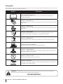 6
6
-
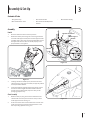 7
7
-
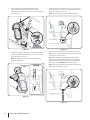 8
8
-
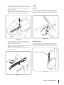 9
9
-
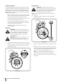 10
10
-
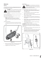 11
11
-
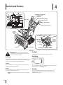 12
12
-
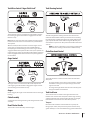 13
13
-
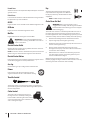 14
14
-
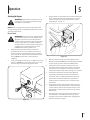 15
15
-
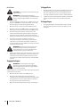 16
16
-
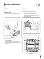 17
17
-
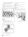 18
18
-
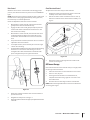 19
19
-
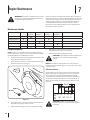 20
20
-
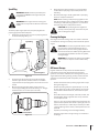 21
21
-
 22
22
-
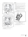 23
23
-
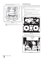 24
24
-
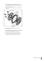 25
25
-
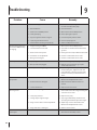 26
26
-
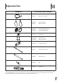 27
27
-
 28
28
-
 29
29
-
 30
30
-
 31
31
-
 32
32
-
 33
33
-
 34
34
-
 35
35
-
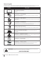 36
36
-
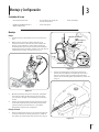 37
37
-
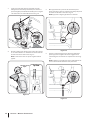 38
38
-
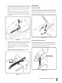 39
39
-
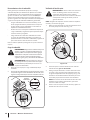 40
40
-
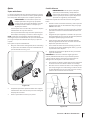 41
41
-
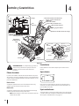 42
42
-
 43
43
-
 44
44
-
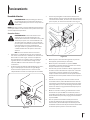 45
45
-
 46
46
-
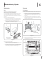 47
47
-
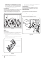 48
48
-
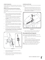 49
49
-
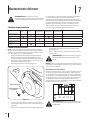 50
50
-
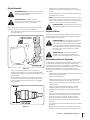 51
51
-
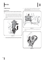 52
52
-
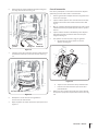 53
53
-
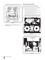 54
54
-
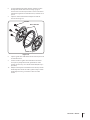 55
55
-
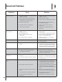 56
56
-
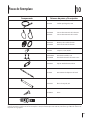 57
57
-
 58
58
-
 59
59
-
 60
60


Troy-Bilt 31BM73Q3766 Manual de usuario
- Categoría
- Lanzadores de nieve
- Tipo
- Manual de usuario
- Este manual también es adecuado para
en otros idiomas
- English: Troy-Bilt 31BM73Q3766 User manual
Artículos relacionados
-
Troy-Bilt 2100 Manual de usuario
-
Troy-Bilt 31AH55Q5711 Manual de usuario
-
Troy-Bilt 31AH64Q4766 Manual de usuario
-
Troy-Bilt 31BM63P3766 Manual de usuario
-
-
Troy-Bilt 31BM73Q3766 Manual de usuario
-
-