La página se está cargando...

# QR813
Owner’s Manual
Manual del usario
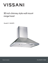
Chimney style stainless steel
range hood
Campana extractora de
chimenea de acero inoxidable

QR813 2
ENGLISH
Table of Contents
Safety Information ..................................2
Warranty ...........................................
One Year Limited Warranty ...........................4
Warranty Claim Procedure ...........................4
Pre-Installation ......................................
Tools Required ....................................5
Package Contents .................................6
Hardware Included .................................6
Planning Installation ...............................7
Installation .......................................10
Operation. . . . . . . . . . . . . . . . . . . . . . . . . . . . . . . . . . . . . . . . . 12
Maintenance ........................................
Filters ..........................................13
Light Bulbs ......................................13
Care and Cleaning ...................................
Range Hood .....................................14
Filters ..........................................14
Troubleshooting ...................................15
Specications .......................................
Wiring Diagram ..................................16
Service Parts ......................................17
MANUAL DEL USARIO ...............................18
Safety Information
READ AND SAVE THESE INSTRUCTNIONS
Warning - To reduce the risk of re, electric shock, or injury to
persons, observe the following:
1. Use this unit only in the manner intended by the manufacturer. If
you have any questions, contact the manufacturer.
2. Before servicing or cleaning unit, switch power off at service
panel and lock service disconnecting means to prevent
power from being switched on accidentally. When the service
disconnecting means cannot be locked, securely fasten a
prominent warning device, such as a tag, to the service panel.
3. Installation work and electrical wiring must be done by qualied
person(s) in accordance with all applicable codes and standards,
including re-rated construction.
4. Sufcient air is needed for proper combustion and exhausting
of gases through the ue (chimney) of fuel burning equipment
to prevent back drafting. Follow the heating equipment
manufacturer's guideline and safety standards such as those
published by the National Fire Protection Association (NFPA)
and the American Society for Heating, Refrigeration and Air
Conditioning Engineers (ASHRAE), and the local code authorities.
5. When cutting or drilling into wall or ceiling, do not damage
electrical wiring and other hidden utilities.
6. Ducted fans must always be vented to the outdoors.
WARNING: FUEL (GAS) BURNING RANGES MUST BE VENTED
OUTDOORS USING, AT MINIMUM, METAL DUCTWORK AND RANGE
HOODS OF SUFFICIENT CAPACITY. Follow your fuel burning
equipment manufacturer’s guidelines, as well as, all applicable
safety standards published by the National Fire Protection
Association (NFPA), and the American Society for Heating,
Refrigeration and Air Conditioning Engineers (ASHRAE), and your
local code authorities.
DANGER: Turn off the power circuit breaker or the power
switch on the junction box before installing or servicing
this unit. Touching circuitry inside the range hood while it is
energized will result in death or serious injury.
DANGER: All electrical wiring must be properly installed,
insulated, and grounded. Improper insulation and grounding
will result in deadly electrical shock.
DANGER: If installing this unit over a gas range, turn off the
gas at the source before installing or servicing this unit.
WARNING: Attempting to install or service this unit when
you do not have the necessary technical or electrical
background could result in personal injury.
WARNING: This unit has sharp edges. Always wear safety
gloves during installation, cleaning, or servicing.
WARNING: Always leave safety grills and lters in place.
Without these components, operating fans could catch on to
hair, ngers, or loose clothing.
WARNING: Stay clear of the rotating fan when the motor is
running.
WARNING: Keep this appliance clean and free of grease
and residue build-up at all times to prevent res.
CAUTION: This device is for general ventilating use only.
Do not use to exhaust hazardous or explosive materials and
vapors.

3
Please contact vissani@conglom.com or 1-888-449-9197 between 8:30 am - 5 pm, EST, Monday - Friday for further assistance.
ENGLISH
Safety Information
COOKING SAFETY INFORMATION
1. Never leave the range hood unattended when in use.
2. Never cook over open ames under the range hood.
3. Always turn the range hood on when cooking at high heat
or when cooking aming foods.
4. The minimum installation distance above the range (3) is 24 in.
(610 mm). Use extra caution as the surface of the range hood
may become extremely hot to the touch if the range is operated
on high power for an extended amount of time.
5. Use caution when cooking with oil or with deep-fryers.
Overheating may cause oil to reach its ash point and ignite.
Used oil will ignite at lower temperatures than fresh oil. Heat
oils slowly on low to medium setting.
6. Avoid boil overs, as they may cause smoking and greasy
spillovers that could ignite.
7. To prevent burns or res, always use cookware appropriate to
the size of the heating element that you are using.
8. In event of a cooking re, observe the following:
- Be careful to avoid burns.
- Smother ames with a close-tting lid, cookie sheet, or
metal tray, then turn off the burner. If the ames do not go
out immediately, evacuate and call the re department.
- Never pick up a aming pan.
- Do not use water, including wet dishcloths or towels, as you
could cause a steam explosion.
- Use an extinguisher only if: (a) you have a class ABC
extinguisher and you know how to operate it, (b) the re is
small and contained in the area where it started, (c) the re
department is being called, and (d) you can ght the re with
your back to the exit.
CLEANING SAFETY INFORMATION
1. The fan and lters must be cleaned periodically and kept free
from accumulation of cooking residue. Old and worn lters must
be replaced immediately.
2. Never disassemble parts to clean. Parts should be disassembled
by qualied persons only.
WARNING: To reduce the risk of re, use only metal duct
work. Never use plastic duct work.
WARNING: To reduce the risk of re or electric shock, do
not use this range hood with any external solid state speed
control device.
CAUTION: For general ventilation use only. Do not use the
range hood fans to exhaust hazardous or explosive vapors.
CAUTION: Never dispose of cigarette ashes, ignitable
substances, or any foreign objects in fans.
CAUTION: At least two people are needed to move and
safely install the unit. Failure to properly lift the range hood
could result in product damage or personal injury.
CAUTION: To reduce risk of re and to properly exhaust
air, be sure to duct air outside-do not vent exhaust air into
spaces within walls or ceilings or into attics, crawl spaces,
or garage.
3
Fig. 1

QR813 4
ENGLISH
Warranty
ONE YEAR LIMITED WARRANTY
A thorough inspection must be made before installation and any damage must be promptly reported. We will not be liable for failures or
damage that could have been discovered or avoided by proper inspection and testing prior to installation.
Vissani warrants this product to be free from defects in materials or workmanship for one (1) year from the date of purchase. Proof of
purchase (original sales receipt) from the original consumer purchaser must be made available to Vissani for all warranty claims.
This warranty is non-transferable and shall be voided if the unit is removed from its initial installation or if it is not installed following the
manufacturer’s instructions. It does not apply in the event of product damage due to the use of other than genuine replacement parts,
(Replacement parts may be obtained by e-mail at vissani@conglom.com or by calling 1-888-449-9197 between 8:30 am - 5 pm, EST, Monday
- Friday) installation error, abuse, misuse or improper care and maintenance (whether performed by a plumber, contractor, service provider or
member of the purchaser’s household). The warranty excludes damage due to aggressive air or water conditions, harsh or abrasive cleaners
and/or materials.
Under no circumstance shall we be held liable for personal injury or property damage resulting from improper installation or use of this
product. We will not be held liable for inconvenience caused by loss of use of this product, costs incurred for materials, removal and installation
of replacement units, or any other incidental or consequential damages. Costs relating to obtaining access for repair or replacement are the
responsibility of the user.
Our obligation shall be limited to the repair or replacement of a unit (at our discretion) that may prove, by our sole examination, to be defective
under normal use and service during the warranty period.
Any failure of this product that is not traceable to a defect in material or workmanship is not covered by this warranty. These non-warrantable
items include, but are not limited to:
- Improper installation not in accordance with manufacturer’s instructions.
- Dents and/or scratches incurred during shipping, handling, or installation.
- Change in color or nish due to chemical usage.
- Damage caused by failure to follow care and cleaning guidelines, including damage caused by the use of abrasive cleaners.
- Alterations made to the unit by the purchaser or installer.
- Damage caused by accidental impact, re, ood, freezing, and normal wear.
- Bends and warping caused by forced connections, over-tightened ttings, and inadequate support during installation.
- Any damage to light bulbs.
WARRANTY CLAIM PROCEDURE
If a claimable defect occurs or replacement parts are needed, please contact our customer service team at vissani@conglom.com or
1-888-449-9197 between 8:30 am - 5 pm, EST, Monday - Friday.
Before you make your call, please ensure that you have:
- Model number or description.
- Proof of sale.
- Details regarding the defect and/or part number.
- Name(s) and address(es) of the owner and/or installer.

5
Please contact vissani@conglom.com or 1-888-449-9197 between 8:30 am - 5 pm, EST, Monday - Friday for further assistance.
ENGLISH
Pre-Installation
TOOLS REQUIRED
Measuring tape Level Utility knife
Marker or pencil Duct tape Adjustable wrench
Phillips screwdriver
Flathead
screwdriver
Electric drill
or powered
screwdriver
Safety goggles Safety gloves

QR813 6
ENGLISH
Pre-Installation (continued)
PACKAGE CONTENTS
Carefully check the range hood for damage and for missing parts prior to installation. If there is any damage or if you are missing parts, do
not proceed with the installation. Report damage and missing parts immediately. Do not dispose of packaging before you are satised with
your new range hood.
A
B C
D
E
F
G H
Part Description Quantity
A
Range hood (including pre-installed
controls, lights, blower, lters and damper)
1
B Lower chimney 1
C Upper chimney 1
D Range Hood Support Bracket 1
E Upper Chimney Bracket - 8" (204 mm) long 1
F Lower Chimney Bracket - 7.6" (194 mm) long 1
G 6" Round Flexible Duct 1
H Charcoal Filters 2
HARDWARE INCLUDED
NOTE:
Parts not shown to actual size.
AA
BB
CC
Part Description Quantity
AA Tapping Screws (ST4 x 30 mm) 9
BB Tapping Screws (ST3 x 10 mm) 2
CC Plastic Wall Anchors 9

7
Please contact vissani@conglom.com or 1-888-449-9197 between 8:30 am - 5 pm, EST, Monday - Friday for further assistance.
ENGLISH
Pre-Installation (continued)
PLANNING INSTALLATION
Number of people required: 2 strongly recommended.
1. Choose a location for your range hood. The range hood location
should be away from strong draft areas, such as windows, doors,
and strong heating vents.
2. Measure all distances to ensure the proper position of the range
hood (A) and chimney set (B, C).
- The size of the range hood installation location must have
a width (1) of at least 35.5 in. (900 mm) and a depth (2) of
at least 19.7 in. (500 mm) to accommodate the size of the
range hood (A).
- The minimum distance (3) from the cooking surface to
the range hood is 24" (610 mm). If your range species a
different distance, use the greater distance of the two. For
best performance, distance (3) should not exceed 36 in
(914 mm).
3. Supplied mounting hardware can be used to secure the hood
to most wall types. However, a qualied technician must verify
suitability of the supplied mounting hardware for your wall type.
4. Due to the size and weight of this range hood, the supports must
be rmly attached to the wall. For plaster or sheet rock walls, the
support must be attached to the studs. If this is not possible, a
support structure must be built behind the plaster or sheet rock.
5. Put a thick, protective covering over your counter, cooktop, or
range to protect it from damage and dirt during installation.
Remove any hazardous objects around the area.
WARNING: Always wear safety goggles and gloves during
installation.
NOTE:
Do not remove the plastic covering on the chimney set at this time,
as it protects the chimney set from scratches during installation.
3
C
B
A
1
2
Fig. 2

QR813 8
ENGLISH
Pre-Installation (continued)
6. For ducted installations, adjust old duct work or install included
new duct work, as necessary, by following these guidelines:
- Your venting system must vent to the outdoors either
horizontally through the back wall (4) or vertically through
the roof (5).
- A straight, short duct run will allow the hood to perform
most efciently. Long duct runs, with elbows and
transitions will reduce the performance of the range hood.
Use as few of them as possible.
- Use round metal duct work with a uniform diameter of
6 in. (152 mm) (included). Larger ducting may be required
for best performance with longer duct runs.
- Before making cuts, make sure there is proper clearance
within the ceiling or wall for the exhaust vent.
- Fasten all connections between pieces of duct with sheet
metal screws and tape all joints with certied duct tape.
- Cap the exterior of the duct with a wall cap (6) or roof
cap (7).
4
6
5
7
Fig. 3

9
Please contact vissani@conglom.com or 1-888-449-9197 between 8:30 am - 5 pm, EST, Monday - Friday for further assistance.
ENGLISH
Pre-Installation (continued)
INSTALLING SUPPORT BRACKETS
- Draw a vertical center line (1) on the supporting wall up to the ceiling, or as
high as pratical, at the center of the area in which the hood will be installed.
- Draw a horizontal line (2) above the range at the preferred distance between
24 - 36 in (610 -914 mm). Consult the user manual of your range if so
required.
- Position the range hood support bracket (D) on the wall about 11.8 in. (300
mm) from the line (2) to the mounting holes, aligning the center with the
vertical reference line (1). Mark the mounting hole locations.
- Position the lower chimney support (F) on the wall about 17.94 in. (456
mm) from the range hood support bracket (D), aligning the center with the
vertical reference line (1). Mark the mounting hole locations.
- Position the mounting holes of the upper chimney support (E) on the wall
0.75 in. (19mm) from the ceiling, aligning the center with the vertical
reference line(1). Mark the mounting hole locations. If the distance between
lower and upper chimney support bracket holes is more than 18.8 in (478
mm) then the range hood support bracket (D) and the lower chimney
support bracket (F) should be raised to ensure the upper chimney is
installed ush with the ceiling.
- Check to ensure the supplied power cable is long enough to reach your
grounded electrical outlet. See "INSTALLING THE WIRING" for more details.
- Once you are satised with the layout, drill pilot holes at the marked
locations.
INSTALLING THE WIRING
DANGER: Risk of electrical shock. This range hood must be
properly grounded.
DANGER: Turn off the power circuit breaker or the power
switch on the junction box before installing or servicing
this unit. Touching circuitry inside the range hood while it is
energized will result in death or serious injury.
DANGER: All electrical wiring must be properly installed,
insulated, and grounded. Improper insulation and grounding
will result in deadly electrical shock.
- It is the customer’s responsibility to contact a qualied electrical installer
and assure that the electrical installation is adequate and complies with
the National Electrical Code, or CSA standards, as well as all local codes
and ordinances.
- This range hood is equipped with a cable with a grounding wire and a
grounding plug. The plug must be plugged into an electrical outlet that is
properly installed and grounded.
- The outlet shall be located within an area covered by the decorative
chimney as shown in gure 5.
Ceiling
18.8 in. or less.
(478 mm)
17.94 in.
(455.8 mm)
11.8 in.
(300.2 mm)
24 - 36 in.
(610 - 914 mm)
6.89 in.
(175 mm)
E
F
0.75 in. (19 mm)
Fig. 4
6.5 in.
(165 mm)
5.9 in.
(150 mm)
IMPORTANT:
Installation work and electrical wiring must be done by a qualied
person(s) in accordance with all applicable codes and standards,
including re-rated construction.
Hood
Centerline
3 in. MAX
(76 mm)
36 in. MAX
(914 mm)
Fig. 5

QR813 10
ENGLISH
Installation
ATTACHING THE SUPPORT BRACKETS
- Use appropriate hardware to fasten the supplied support
brackets to your wall.
- If fastening hardware supplied with this range hood is
appropriate for your wall type, enlarge the pilot holes using
a 1/4 in. (6 mm) drill bit. Install the plastic wall anchors
(CC) and fasten the brackets using the supplied tapping
screws (AA).
INSTALLING THE DAMPER (IF NECESSARY)
WARNING: Sharp edges. Wear safety gloves.
CAUTION: Be very careful when installing the damper.
Applying too much force or bending the damper too much
may damage or break the damper hinge ends.
The damper is pre-installed at the factory. Make sure that it has
not come loose during shipping and that it opens freely. Re-
install it if necessary.
- Insert one end of the damper (3) into the hinge slot (4) at
the top of the range hood (A).
- Gently bend the damper (3) and insert its other end into the
hinge slot (4).
Fig. 6
A
3
4
3
Fig. 7
INSTALLING THE RANGE HOOD
CAUTION: Make sure the range hood is secure before
releasing it.
- Hang the range hood on the range hood support bracket (D)
and mark the locations of the two mounting holes inside the
range hood. Take the range hood off the wall and drill two
pilot holes in the marked locations.
- If fastening hardware supplied with this range hood is
appropriate for your wall type, enlarge the pilot holes using a
1/4 in. (6 mm) drill bit and install the plastic wall anchors (CC).
Lastly, hang the range hood back on the range hood support
bracket (D) and secure to the wall with two tapping screws
(AA).
Fig. 8

11
Please contact vissani@conglom.com or 1-888-449-9197 between 8:30 am - 5 pm, EST, Monday - Friday for further assistance.
ENGLISH
Installation (continued)
ATTACHING THE DUCT (FOR OUTDOOR VENTED
INSTALLATIONS)
WARNING: FUEL (GAS) BURNING RANGES MUST BE VENTED
OUTDOORS USING, AT MINIMUM, METAL DUCTWORK AND RANGE
HOODS OF SUFFICIENT CAPACITY.
NOTE:
In interior vented installations, air is recirculated through a charcoal
lters and exhausted through the top of the chimney. Skip this step if
you are recirculating the air indoors.
- Attach the supplied duct (G) to the range hood (A) and
connect it to your exterior duct using duct tape.
INSTALLING THE CHIMNEY
WARNING: Sharp edges. Wear safety gloves.
- Plug the range hood into the grounded electrical outlet and make
sure it is operating correctly before proceeding.
- Place the upper chimney (C) inside the lower chimney (B) and
place them both onto the range hood. Hang the lower chimney
(B) on the lower support bracket (F) as shown in gure 9.
- Slide the upper chimney (C) upwards and hang it on the upper
chimney support bracket (E) as shown in gure 11.
- Secure the chimney extensions to the support brackets with
tapping screws (BB) from both sides as shown in gure 11.
Fig. 9
A
G
C
B
C
B
E
E
E
E
BB
E
Fig. 10
Fig. 11

QR813 12
ENGLISH
Operation
Fig. 12
STANDBY STATE
- Once the range hood is powered it remains in a stand
by state.
TIMER DELAYED SHUTDOWN
- You can set a custom shut down delay time by pressing
the time button (5) and adjusting the timer using the +
and - buttons.
TURN ON FAN
- Press the power button (1) to quickly activate both
the fan and light at once. Press the + button (3) and -
button (4) to control fan speed.
- Alternatively you can press the fan button (2) to activate
the fan only.
TWO LEVEL LIGHTING
- Press the light button (6) at anytime to activate the light
at low level. Press the light button (6) a second time to
set the light to high level. Press the light button (6) a
third time to turn it off.
TURNING OFF FAN
- Press the fan button (2) or the power button (1) while
the fan is operating to deactivate it.
SETTING THE CLOCK
- Press and hold the time button (5) until the display starts
ashing. Press the + and - buttons to set the correct time.
Press the time button (5) again to set desired time.

13
Please contact vissani@conglom.com or 1-888-449-9197 between 8:30 am - 5 pm, EST, Monday - Friday for further assistance.
ENGLISH
Maintenance
FILTERS
Bafe lters should be cleaned regularly using a warm, mild
dish-washing detergent solution. Damaged bafe lters should be
replaced.
Charcoal lters should only be used in indoor-vented (recirculating)
ventilation systems and should be replaced periodically, depending
on frequency of use.
- Turn off the range hood and disconnect the power.
- While holding the bafe lter, press the lock knob and
remove the lter. Clean the lter and ensure the bafe lter
is dry before reinstallation.
- Charcoal lters are installed directly onto the motor
housing. Slide the lter onto the lock feature in the center
for the grille and rotate it until it locks into posion.
DANGER: Turn off the power circuit breaker or the power
switch on the junction box before performing maintenance.
Touching circuitry inside the range hood while it is
energized will result in death or serious injury.
WARNING: Failure to replace worn out or damaged lters
will increase the risk of re.
Fig. 14
LIGHT BULBS
WARNING: Light bulbs can become hot when turned on.
Do not touch bulbs until they are switched off and cooled.
Touching hot bulbs could cause serious burns.
When light bulbs burn out, replace them with factory approved
replacement bulbs available from our customer service team.
- Turn off the range hood, disconnect it from its power source,
and ensure that the lights are cool.
- Remove the lters and gently press on the bulbs from
inside the range hood to remove them. Disconnect the bulb
connector.
- Connect a new replacement bulb to the bulb connector and
and gently press the bulb back into the the bulb opening until
it locks into place.
- Reinstall the lters and restore the power to the range hood.
Fig. 15

QR813 14
ENGLISH
Care and Cleaning
RANGE HOOD
WARNING: Failure to maintain basic standards of care and cleaning of the range hood will increase the risk of re.
The range hood should be cleaned (regularly internally and externally) to preserve its appearance and performance.
Do: Do Not:
- Always clean in the direction of the grain (original
polish lines).
- Clean the range hood periodically with hot, soapy
water and a clean cotton cloth.
- Always rinse well with clean water two or three
times after cleaning. Wipe completely dry with a
soft non-abrasive cloth.
- After cleaning, you may polish with a non-abrasive
stainless steel polish or cleaner. Always rub lightly
and with the grain.
- Ensure that the venting system is free of debris, if
you have one.
- Do not use abrasive detergents, steel wool, or
scouring pads. These will scratch and damage the
stainless steel surface.
- Do not use corrosive detergents, or any products
containing chloride, uoride, iodide, or bromide on this
product, as they will deteriorate the surface rapidly.
- Do not allow cleaning compounds, salt solutions,
disinfectants, or bleaches to remain in contact with
the product for extended periods of time.
- Do not allow deposits to remain for long periods of
time on the range hood. Rinse with water immediately
and wipe dry with a clean cloth.
- Do not let plaster dust or any other construction
residue enter the hood. During construction or
renovation, cover the hood.
- Combustible products used for cleaning such as acetone,
alcohol, ether, or benzol are highly explosive and should
never be used close to a range or stove.
FILTERS
The bafe lters are intended to lter out residue and grease from cooking. You do not need to replace them on a regular basis,
but you should keep them clean.
Do: Do Not:
- Clean the lters once a month using non-abrasive
detergents, either by hand or in the dishwasher.
When using a dishwasher, set the dishwasher to
a low temperature and a short cycle setting. The
lter may become discolored in a dishwasher, but
this does not affect its performance.
- Dry the lters before re-installing them in the
range hood.
- Do not allow oil to accumulate over more than 80%
of the lter surface. Oil accumulations may drip oil
onto the range.

15
Please contact vissani@conglom.com or 1-888-449-9197 between 8:30 am - 5 pm, EST, Monday - Friday for further assistance.
ENGLISH
Troubleshooting
DANGER: Turn off the power circuit breaker or the power switch on the junction box before performing maintenance. Touching circuitry inside
the range hood while it is energized will result in death or serious injury.
Problem Solution
The range hood will not operate.
- Check that the power supply cable and all electrical wiring are properly
connected.
- Check that the power is turned on at the junction box or circuit breaker.
- Check that the wiring between the switch control and the control board are
connected properly.
The range hood vibrates when the fan is operating.
- Check that the range hood has been secured properly to the wall. Tighten into
position, if necessary.
- Check that the motor is secured in place. If not, then tighten the motor in place.
- Check that the fan is not damaged. If so, replace the fan.
The fans seem weak.
- Check that the duct size used is at least 6 in. (152 mm) round. The range hood
will not function efciently with insufcient duct size.
- Check that the duct is not clogged with debris and the tight mesh on the wall
cap, if applicable, isn’t restricting air ow.
- Check that the damper unit is opening properly.
- Check that no birds or animals have nested in the duct.
The lights work, but the fan is not spinning, is stuck,
or is rattling.
- The thermal protection system detects if the motor is too hot to operate and
shuts the motor down. In this case, the motor will function properly after the
thermal protection system cools down (after approximately 10 min.).
- Check that the fan isn’t jammed.
- If nothing else works, the motor may be defective or seized. If so, replace the
motor.
The range hood is not venting properly. - Check that no birds or animals have nested in the duct.
- Check that the distance between the cooktop and the bottom of the range hood
is within the previously recommended distance.
- Check that duct work follows all requirements. Use round metal duct work with
a uniform diameter of 6 in. (152 mm). The length of duct work must not exceed
35 ft (10.7 m). Reduce the length of duct work and the number of elbows if
necessary. Ensure that all joints are properly connected, sealed, and taped.
- Check that the duct does not open against the wind.
- Ensure that the power is on high speed for heavy cooking.
- Wind from opened windows or doors may affect the performance of the range
hood. Close all windows and doors to eliminate outside air ow.
- To enhance the performance of the range hood, open slightly a window on the
opposite side of the house where the range hood vents outdoors.
The light does not work. - Check to see if light bulb is burnt. If so, replace.
- Check to ensure the light bulb is connected properly.

QR813 16
ENGLISH
Specications
6.6 in
(168 mm)
8.2 in
(208 mm)
2.4 in
(60 mm)
35.2 in
(895 mm)
19.7 in
(500 mm)
11 in
(279 mm)
30.3 - 48 in
(770 - 1220 mm)
Model Dimensions Rating Speeds CFM Control Type Illumination Venting Options
QR813
35.2 in (895 mm) W
120 V /
60 Hz /
3.6A
3
500 ±
10%
Max
Electronic Touch
Switch
2 x 1.5 W LED Light
Top venting/
Recirculating
19.7 in (500 mm) D
11 in (279 mm) H
Lower Chimney 8.2 in. W x 6.6 in. D x 19.7 in. H (208 mm W x 168 mm D x 500 mm H)
Upper Chimney 8.1 in. W x 6.5 in. D x 19.7 in. H (205 mm W x 165 mm D x 500 mm H)
WIRING DIAGRAM
PCB
Yellow
Orange
Black
Grey
White
Blue
Black Red

17
Please contact vissani@conglom.com or 1-888-449-9197 between 8:30 am - 5 pm, EST, Monday - Friday for further assistance.
ENGLISH
Service Parts
If you are missing parts or if you require replacement parts, please contact our customer service team at vissani@conglom.com or
1-888-449-9197 between 8:30 am - 5 pm, EST, Monday - Friday. Identify the required part(s) and have the part number(s) ready.
E
F
G
A B
H
AA BB CC
C
D
Part Description Code Quantity Part Description Code Quantity
A Control board QHR230 1 AA Tapping Screws (ST4 x 30 mm) QHR238 9
B Control panel QHR231 1 BB Tapping Screws (ST3 x 10 mm) QHR239 2
C Charcoal Filters QHR232 2 CC Plastic Wall Anchor QHR240 9
D 6" Round Flexible Chimney QHR233 1
E Motor and fan set QHR234 1
F Capacitor QHR235 1
G Light QHR236 2
H Bafe Filter QHR242 3

QR813 18
ESPAÑOL
Índice
OWNER’S MANUAL ..................................2
Información de seguridad ...........................18
Garantía. . . . . . . . . . . . . . . . . . . . . . . . . . . . . . . . . . . . . . . . . . . .
Un año de garantía limitada .........................20
Procedimiento de reclamación de garantía .............20
Preinstalación .......................................
Herramientas requeridas ...........................21
Contenido del paquete .............................22
Accesorios incluidos ..............................22
Planicación de la instalación .......................23
Instalación .......................................26
Funcionamiento ...................................28
Mantenimiento ......................................
Filtros ..........................................29
Bombillas .......................................29
Cuidado y limpieza ...................................
Campana extractora. . . . . . . . . . . . . . . . . . . . . . . . . . . . . . . 30
Filtros ..........................................30
Solución de problemas ..............................31
Especicaciones .....................................
Diagrama de cableado .............................32
Piezas de refacción ................................33
Información de seguridad
LEA Y GUARDE ESTAS INSTRUCCIONES
Advertencia: Para reducir el riesgo de incendio, descarga eléctrica o
lesiones a las personas, tenga en cuenta lo siguiente:
1. Use esta unidad exclusivamente de la manera concebida por el
fabricante. Si tiene alguna pregunta, póngase en contacto con el
fabricante.
2. Antes de darle mantenimiento a la unidad o de limpiarla, apague el
suministro eléctrico en el panel de servicio y bloquee el medio de
desconexión para evitar que el equipo se encienda accidentalmente.
Cuando el medio de desconexión del servicio no se pueda bloquear,
adhiera de manera segura un dispositivo visible de advertencia al panel
de servicio, tal como un rótulo.
3. El trabajo de instalación y el cableado eléctrico debe llevarse a cabo
por personas calicadas, de acuerdo con todos los códigos y normas
aplicables, lo que incluye una construcción calicada a prueba de
incendios.
4. Se necesita una cantidad suciente de aire para lograr una
combustión correcta y el escape de los gases a través del conducto
de humos (chimenea) de los equipos que queman combustible para
evitar el contratiraje. Siga las especicaciones del fabricante del
equipo de calentamiento y las normas de seguridad, tales como
aquellas publicadas por la Asociación Nacional de Protección contra
Incendios (National Fire Protection Association, NFPA) y la Sociedad
Estadounidense de Ingenieros de Calefacción, Refrigeración y Aire
Acondicionado (American Society for Heating, Refrigeration and Air
Conditioning Engineers, ASHRAE), así como por los códigos de las
autoridades locales.
5. Al cortar o perforar en pared o cielo raso, no dañe el cableado eléctrico
ni otros servicios ocultos.
6. Los ventiladores con conductos siempre deben tener salida al exterior.
ADVERTENCIA: LAS HORNILLAS DE GAS DEBEN VENTILARSE EN EXTERIORES
UTILIZANDO, POR LO MENOS, CONDUCTOS METÁLICOS Y CAMPANAS
EXTRACTORAS DE CAPACIDAD SUFICIENTE. Siga las especicaciones
del fabricante del equipo quemador de combustible y las normas de
seguridad correspondientes, como las que publica la Asociación Nacional
de Protección contra Incendios (National Fire Protection Association, NFPA)
y la Sociedad Estadounidense de Ingenieros de Calefacción, Refrigeración
y Aire Acondicionado (American Society for Heating, Refrigeration and Air
Conditioning Engineers, ASHRAE), así como los códigos de las autoridades
locales.
PELIGRO: Apague el disyuntor o el interruptor de alimentación
en la caja de derivación antes de instalar o dar servicio a esta
unidad. No toque los circuitos que se encuentran dentro de la
campana extractora mientras está conectada, pues esto puede
ocasionar la muerte o una lesión grave.
PELIGRO: Todos los cables eléctricos deben instalarse,
aislarse y conectarse a tierra apropiadamente. Si el
aislamiento y la conexión a tierra no son adecuados, existe
el riesgo de que se produzca una descarga eléctrica mortal.
PELIGRO: Si va a instalar la unidad sobre una estufa de
gas, apague la fuente de gas antes de la instalación o de
darle mantenimiento a la unidad.
ADVERTENCIA: No intente instalar o dar servicio a
esta unidad si no tiene los conocimientos técnicos o de
electricidad necesarios, ya que podría sufrir alguna lesión.
ADVERTENCIA: La unidad tiene bordes alados. Siempre
use guantes de seguridad al instalarla, limpiarla o darle
mantenimiento.
ADVERTENCIA: Siempre deje los ltros y las rejillas de
seguridad en su lugar. Sin estos componentes, cuando los
ventiladores están en funcionamiento se puede atorar el
cabello, los dedos o la ropa suelta.
ADVERTENCIA: Manténgase lejos del ventilador giratorio
cuando el motor esté funcionando.
ADVERTENCIA:
Mantenga el dispositivo limpio y sin grasa ni
acumulación de residuos en todo momento para evitar incendios.
PRECAUCIÓN: El uso de este dispositivo debe ser
únicamente para ventilación. No lo utilice para expulsar
materiales y vapores peligrosos o explosivos.

19
Por favor, contacte vissani@conglom.com o llamé al 1-888-449-9197 de 8:30 a.m. a 5:00 p.m.,
EST, de lunes a viernes, para obtener más ayuda.
ESPAÑOL
Información de seguridad
INFORMACIÓN DE SEGURIDAD AL COCINAR
1. Nunca deje la campana de extracción sin supervisión cuando
esté funcionando.
2. Nunca cocine sobre llamas abiertas debajo de la campana de
extracción.
3. Siempre encienda la campana extractora cuando cocine con
fuego alto
o cuando cocine alimentos ameados.
4. La distancia mínima de instalación por encima de la estufa (3)
es de 24 pulgadas (610 mm). Tenga especial cuidado, ya que la
supercie de la campana podría estar extremadamente caliente
al tacto si la estufa estuvo funcionando con fuego alto durante
un periodo largo.
5. Tenga cuidado al cocinar con aceite o al freír con una freidora.
El sobrecalentamiento puede ocasionar que el aceite alcance
su punto de ignición y se incendie. El aceite usado se incendia a
temperaturas inferiores que el aceite nuevo. Caliente los aceites
lentamente jando el control a una temperatura baja o media.
6. No permita que los líquidos se derramen cuando los hierva, ya
que pueden ocasionar humos y derrames grasosos que pueden
incendiarse.
7. Para evitar quemaduras o incendios, siempre use el equipo de
cocina apropiado para el tamaño de la hornilla o quemador que
use.
8. En caso de que haya fuego al cocinar, siga las indicaciones que
presentamos a continuación:
- Tenga cuidado para no quemarse.
- Sofoque las llamas con una tapa que cierre herméticamente,
con una lámina para hornear galletas o una bandeja
metálica; posteriormente, apague el hornillo o quemador. Si
las llamas no se apagan de inmediato, evacue y llame a los
bomberos.
- Nunca levante una sartén en llamas.
- No use agua, trapos de cocina húmedos ni toallas, ya que
puede ocasionar una explosión de vapor.
- Use un extintor únicamente si: (a) es tipo ABC y sabe cómo
manejarlo, (b) el fuego es pequeño y está contenido en el
área donde comenzó, (c) si el departamento de bomberos ya
fue avisado, y (d) puede extinguir el incendio con su espalda
orientada hacia a la salida.
INFORMACIÓN DE SEGURIDAD PARA LIMPIEZA
1. El ventilador y los ltros deben limpiarse periódicamente y
mantenerse libres de acumulación de los residuos generados al
cocinar. Los ltros viejos y desgastados deben ser reemplazados
de inmediato.
2. Nunca desarme las partes que van a limpiarse. Las partes deben
ser desarmadas únicamente por personal calicado.
ADVERTENCIA: Para reducir el riesgo de incendio, utilice
sólo ductos metálicos. Nunca utilice ductos de plástico.
ADVERTENCIA: Para reducir el riesgo de incendio o
descarga eléctrica, no use esta campana con ningún
dispositivo externo de control de velocidad de estado sólido.
PRECAUCIÓN: El único uso de este dispositivo debe ser
de ventilación. No use los ventiladores de la campana
extractora para sacar vapores peligrosos o explosivos.
PRECAUCIÓN: Nunca tire cenizas de cigarrillo, sustancias
inamables ni objetos externos en los ventiladores.
PRECAUCIÓN: Se requieren al menos dos personas para
mover e instalar la unidad con seguridad. El no levantar
adecuadamente la campana extractora podría ocasionar
daños en el producto o lesiones personales.
PRECAUCIÓN: Para reducir el riesgo de incendio y dejar
escapar el aire de manera adecuada, asegúrese de conducir
el aire hacia el exterior, no dirija el aire de escape hacia las
paredes o techos, espacios cerrados, áticos, entrepisos ni
cocheras.
3
Fig. 1

QR813 20
ESPAÑOL
Garantía
UN AÑO DE GARANTÍA LIMITADA
Se debe realizar una inspección a conciencia antes de la instalación y reportar inmediatamente cualquier daño. No nos hacemos responsables
por fallos o daños que pudieran haberse descubierto o evitado con una inspección y pruebas adecuadas antes de la instalación.
Vissani garantiza este producto contra defectos en materiales y de fabricación durante 1 (un) año a partir de la fecha de compra. Es necesario
que el comprador original entregue a Vissani el comprobante de compra (recibo original) para todos los reclamos relacionados con la garantía.
Esta garantía no es transferible y será anulada si la unidad se quita del lugar donde se instaló inicialmente o si no se instala de acuerdo con
las instrucciones del fabricante. La garantía no se aplica en caso de daños en el producto debidos al uso de piezas distintas a los repuestos
originales (las piezas de repuesto se pueden obtener enviando un correo electrónico a vissani@conglom.com o llamando al 1-888-449-9197
entre las 8:30 am. y las 5:00 pm, hora del Este, de lunes a viernes), a los errores de instalación, el maltrato, el uso indebido y el cuidado y
mantenimiento inapropiados (sin importar si los realiza un plomero, contratista, proveedor de servicios o familiar del comprador). La garantía
no incluye los daños debidos a condiciones agresivas del aire o el agua, ni al uso de limpiadores o materiales fuertes o abrasivos.
Bajo ninguna circunstancia seremos responsables de lesiones físicas o daños a la propiedad que sean consecuencia de una instalación o
uso inapropiados de este producto. No seremos responsables por inconvenientes ocasionados por pérdida de uso de este producto, costos
incurridos en materiales, retiro e instalación de unidades de reemplazo, ni ningún otro daño incidental o consecuente. Los costos relacionados
con la obtención de acceso para la reparación o el reemplazo son responsabilidad del usuario.
Nuestra obligación se limita a la reparación o reemplazo de una unidad (a nuestra discreción) cuando pueda comprobarse, únicamente al
examinarla nosotros, que tiene defectos en circunstancias de uso y servicio normal durante el periodo de garantía.
Cualquier fallo de este producto que no sea identicable como un defecto en materiales o de fabricación no estará cubierto por esta garantía.
Los aspectos que no se pueden garantizar incluyen, entre otros:
- Instalación indebida sin seguir las instrucciones del fabricante.
- Abolladuras y/o rayones ocasionados durante el transporte, el manejo o la instalación.
- Cambio en el color o acabado debido al uso de productos químicos.
- Daños ocasionados por no seguir las pautas de cuidado y limpieza, incluyendo daños ocasionados por el uso de limpiadores
abrasivos.
- Alteraciones hechas a la unidad por parte del comprador o instalador.
- Daños ocasionados por golpes accidentales, incendios, inundaciones, congelamiento y por el desgaste normal.
- Dobleces y deformaciones causados por conexiones forzadas, accesorios demasiado apretados y soporte inadecuado durante la
instalación.
- Cualquier daño en las bombillas.
PROCEDIMIENTO DE RECLAMACIÓN DE GARANTÍA
Si ocurre un defecto por el que se pueda presentar una reclamación o si se necesitan repuestos, póngase en contacto con nuestro equipo de
servicio al cliente escribiendo a vissani@conglom.com o llamando al teléfono 1-888-449-9197 entre las 8:30 a. m. y las 5:00 p. m., hora del
Este, de lunes a viernes.
Antes de llamar para presentar una reclamación, asegúrese de tener a la mano:
- El número o la descripción del modelo.
- El comprobante de compra.
- Los detalles del defecto y/o el número de pieza.
- Nombre(s) y domicilio(s) del propietario o el instalador.

21
Por favor, contacte vissani@conglom.com o llamé al 1-888-449-9197 de 8:30 a.m. a 5:00 p.m.,
EST, de lunes a viernes, para obtener más ayuda.
ESPAÑOL
Preinstalación
HERRAMIENTAS REQUERIDAS
Cinta métrica Nivel Navaja
Marcador o lápiz Cinta aislante Llave inglesa
Destornillador de estrella
(Phillips)
Destornillador
plano
Taladro eléctrico
o destornillador
eléctrico
Gafas de seguridad Guantes de seguridad

QR813 22
ESPAÑOL
Preinstalación (continuación)
CONTENIDO DEL PAQUETE
Verique cuidadosamente que la campana de extracción no tenga daños y que no falten partes antes de la instalación. Si hay algún daño
o faltan partes, no prosiga con la instalación. Reporte de inmediato los daños y las partes faltantes. No deseche el empaque antes de que
esté satisfecho con su nueva campana de extracción.
A
B C
D
E
F
G H
Pieza Descripción Cantidad
A
Campana extractora (incluyendo los controles,
las luces, el extractor, los ltros y el regulador preinstalados)
1
B Chimenea inferior 1
C Chimenea superior 1
D Soporte de la campana extractora 1
E Soporte superior de la chimenea - 8" (204 mm) de largo 1
F Soporte inferior de la chimenea - 7.6" (194 mm) de largo 1
G Chimenea exible redonda de 6" 1
H Filtros de carbón 2
ACCESORIOS INCLUIDOS
NOTA:
Las piezas no se muestran en su tamaño real.
AA
BB
CC
Pieza Descripción Cantidad
AA Tornillos de rosca (ST4 x 30 mm) 9
BB Tornillos de rosca (ST3 x 10 mm) 2
CC Tarugos 9

23
Por favor, contacte vissani@conglom.com o llamé al 1-888-449-9197 de 8:30 a.m. a 5:00 p.m.,
EST, de lunes a viernes, para obtener más ayuda.
ESPAÑOL
Preinstalación (continuación)
PLANIFICACIÓN DE LA INSTALACIÓN
Número de personas necesarias: Se recomienda enfáticamente que
participen 2 personas.
1. Elija dónde colocar su campana extractora. La ubicación de la
campana extractora debe ser lejos de corrientes de aire como
ventanas, puertas y conductos de calefacción.
2. Mida todas las distancias para asegurarse de la posición adecuada
de la campana extractora (A) y del juego de chimenea (B, C).
- El espacio que se necesita para instalar la campana
extractora debe ser de al menos 35.5 pulgadas de ancho
(1) (900 mm) y al menos 19.7 pulgadas (500 mm) de
profundidad (2) para que la campana de extracción (A)
disponga de suciente espacio.
- La distancia (3) entre la supercie de cocción y
la campana debe ser de al menos 24" (610 mm). Si la estufa
de gas indica una distancia distinta, tome en cuenta la que
sea mayor. Para un mejor rendimiento, esta distancia (3) no
debe ser mayor de 36" (914 mm).
3. Los accesorios de instalación proporcionados pueden usarse
para jar la campana a la mayoría de los muros. Sin embargo, un
técnico especialista debe revisar que en la pared puedan colocarse
los accesorios de instalación proporcionados.
4. Debido al tamaño y el peso de la campana extractora, los soportes
deben sujetarse con rmeza a la pared. Para yeso o tablarroca,
el soporte debe colocarse en los apoyos. De no ser posible, debe
construirse una estructura de soporte detrás del yeso o de la
tablarroca.
5. Coloque una protección gruesa sobre su cubierta, parrillas
y estufa, para evitar que se dañen o se empolven durante la
instalación. Retire cualquier objeto peligroso del área.
ADVERTENCIA: Siempre use gafas y guantes de seguridad
durante la instalación.
NOTA:
No quite la cubierta de plástico del juego de la chimenea aún,
ya que lo protege de raspones durante la instalación.
3
C
B
A
1
2
Fig. 2

QR813 24
ESPAÑOL
Preinstalación (continuación)
6. Para instalaciones con ductos, si es necesario ajustar el viejo
ducto o instalar uno nuevo, siga estas indicaciones:
- Su sistema de ventilación debe llevar el aire hacia el
exterior, ya sea horizontalmente a través de la pared
trasera (4) o verticalmente a través del techo (5).
- Un ducto recto y corto permitirá que la campana funcione
con mayor eciencia. Un ducto largo, curvo o transicional
reducirá el rendimiento de la campana extractora. Trate de
no utilizar estos ductos.
- Utilice un ducto de metal redondo con un diámetro
uniforme de
6 pulgadas (152 mm) (incluido). Es posible que requiera un
ducto más largo para un mejor rendimiento.
- Antes de realizar algún corte, asegúrese de que haya un
espacio libre entre el techo y la pared para la abertura de
escape.
- Ajuste todas las conexiones de los ductos con tornillos
para lámina metálica y aplique cinta especíca para
ductos en todas las juntas.
- Coloque una tapa para pared (6) o una tapa para techo
(7) en el tubo exterior.
4
6
5
7
Fig. 3

25
Por favor, contacte vissani@conglom.com o llamé al 1-888-449-9197 de 8:30 a.m. a 5:00 p.m.,
EST, de lunes a viernes, para obtener más ayuda.
ESPAÑOL
Preinstalación (continuación)
CÓMO INSTALAR LOS SOPORTES
- Dibuje una línea central vertical (1) en la pared de soporte hasta el techo,
o tan alto como convenga, en el centro del área en la que se instalará la
campana.
- Dibuje una línea horizontal (2) por encima de la estufa a la distancia
preferida entre 24 y 36 pulgadas (entre 610 y 914 mm). Consulte el manual
de usuario de la estufa, si es necesario.
- Coloque el soporte de la campana extractora (D) en el muro,
aproximadamente a 11.8 pulgadas (300 mm) desde la línea (2) hasta los
oricios de montaje, alineando el centro con la línea de referencia vertical
(1). Marque las ubicaciones de los oricios de montaje.
- Coloque el soporte de la chimenea inferior (F) en el muro, aproximadamente
a 17.94 pulgadas (456 mm) del soporte de la campana extractora (D),
alineando el centro con la línea de referencia vertical (1). Marque las
ubicaciones de los oricios de montaje.
- Coloque los oricios de montaje del soporte de la chimenea superior (E)
en la pared a 0.75 pulgadas (19 mm) del techo, alineando el centro con
la línea de referencia vertical (1). Marque las ubicaciones de los oricios
de montaje. Si la distancia entre los oricios del soporte de la chimenea
inferior y superior es mayor de 18.8 pulgadas (478 mm), entonces el soporte
de la campana extractora (D) y el soporte de la chimenea inferior (F) deben
elevarse para garantizar que la chimenea superior se instale a ras del techo.
- Verique que el cable de alimentación suministrado sea lo sucientemente
largo como para llegar a la toma eléctrica con conexión a tierra. Consulte
"CÓMO INSTALAR EL CABLEADO" para obtener más información.
- Una vez que esté satisfecho con el diseño, taladre agujeros piloto en las
ubicaciones marcadas.
CÓMO INSTALAR EL CABLEADO
PELIGRO: Riesgo de descarga eléctrica. Esta campana
extractora debe estar conectada correctamente.
PELIGRO: Apague el disyuntor o el interruptor de
alimentación en la caja de derivación antes de instalar o
dar servicio a esta unidad. No toque los circuitos que se
encuentran dentro de la campana extractora mientras está
conectada, pues esto puede ocasionar la muerte o una
lesión grave.
PELIGRO: Todos los cables eléctricos deben instalarse,
aislarse y conectarse a tierra apropiadamente. Si el
aislamiento y la conexión a tierra no son adecuados, existe
el riesgo de que se produzca una descarga eléctrica mortal.
- Es responsabilidad del cliente comunicarse con un instalador eléctrico
calicado y asegurarse de que la instalación eléctrica sea adecuada y
cumpla con el Código Eléctrico Nacional, o con las normas de la CSA y
todos los demás códigos y normas locales.
- Esta campana extractora está equipada con un cable con conexión a tierra
y un enchufe de conexión a tierra. El enchufe debe estar conectado a una
toma eléctrica que esté correctamente instalada y tenga conexión a tierra.
- La toma debe estar ubicada dentro de un área cubierta por la chimenea
decorativa, como se muestra en la gura 5.
Techo
18.8 pulgadas o menos
(478 mm)
17.94 pulg.
(455.8 mm)
11.8 pulg.
(300.2 mm)
24 - 36 pulg.
(610 - 914 mm)
6.89 pulg.
(175 mm)
E
F
0.75 pulg. (19 mm)
Fig. 4
6.5 pulg.
(165 mm)
5.9 pulg.
(150 mm)
IMPORTANTE:
El trabajo de instalación y el cableado eléctrico deberán
realizarlos personas calicadas de acuerdo con todos los
códigos y normas aplicables, lo cual incluye una instalación
contra incendios.
Línea central
de la campana
3 pulg.
MAX
(76 mm)
36 pulgadas MÁX.
(914 mm)
Fig. 5

QR813 26
ESPAÑOL
Instalación
CÓMO COLOCAR LOS SOPORTES
- Use herramientas adecuadas para instalar en la pared los
soportes suministrados.
- Si los accesorios de jación suministrados con esta
campana extractora son adecuados para su tipo de pared,
amplíe los oricios piloto con una broca de 1/4 pulgadas
(6 mm). Instale los tarugos (CC) y je los soportes con los
tornillos de rosca suministrados (AA).
INSTALACIÓN DEL REGULADOR (EN CASO
NECESARIO)
ADVERTENCIA: Hay bordes alados. Utilice guantes de
seguridad.
PRECAUCIÓN: Tenga mucho cuidado cuando instale el
regulador. Si aplica demasiada fuerza o dobla demasiado el
regulador, los extremos de las bisagras se pueden dañar o
romper.
El regulador viene previamente instalado de fábrica. Asegúrese
de que no se haya aojado durante el envío y de que se abre
fácilmente. Vuelva a instalarlo, en caso necesario.
- Introduzca un extremo del regulador (3) en la ranura de la
bisagra (4), en la parte superior de la campana extractora (A).
- Doble con cuidado el regulador (3) e inserte el otro extremo
en la ranura de la bisagra (4).
Fig. 6
A
3
4
3
Fig. 7
INSTALACIÓN DE LA CAMPANA EXTRACTORA
PRECAUCIÓN: Asegúrese de que la campana extractora
esté ja antes de soltarla.
- Coloque la campana extractora en el soporte correspondiente
(D) y marque la ubicación de los dos oricios de montaje
dentro de la campana. Retire la campana extractora de
la pared y taladre dos oricios piloto en las ubicaciones
marcadas.
- Si los accesorios de jación suministrados con esta campana
extractora son adecuados para su tipo de pared, amplíe
los oricios piloto con una broca de 1/4 pulgadas (6 mm)
e instale los tarugos (CC). Por último, coloque la campana
extractora en el soporte correspondiente (D) y fíjela a la pared
con los dos tornillos de rosca (AA).
Fig. 8

27
Por favor, contacte vissani@conglom.com o llamé al 1-888-449-9197 de 8:30 a.m. a 5:00 p.m.,
EST, de lunes a viernes, para obtener más ayuda.
ESPAÑOL
Instalación (continuación)
COLOCACIÓN DEL TUBO (PARA LAS
INSTALACIONES CON VENTILACIÓN EN
EXTERIORES)
ADVERTENCIA: LAS HORNILLAS DE GAS DEBEN VENTILARSE
EN EXTERIORES UTILIZANDO, POR LO MENOS, CONDUCTOS
METÁLICOS Y CAMPANAS EXTRACTORAS DE CAPACIDAD
SUFICIENTE.
NOTA:
En instalaciones con ventilación interior, el aire se recircula
a través de ltros de carbón y se expulsa a través de la parte
superior de la chimenea. Omita este paso si está recirculando el
aire en interiores.
- Conecte el tubo incluido (G) a la campana extractora (A) y
conéctelo al ducto exterior con cinta aislante.
CÓMO INSTALAR LA CHIMENEA
ADVERTENCIA: Hay bordes alados. Utilice guantes de
seguridad.
- Enchufe la campana extractora a la toma eléctrica con conexión a
tierra y asegúrese de que esté funcionando correctamente antes
de continuar.
- Coloque la chimenea superior (C) dentro de la chimenea inferior
(B) y colóquelas en la campana extractora. Cuelgue la chimenea
inferior (B) del soporte inferior (F) como se muestra en la gura 9.
- Deslice la chimenea superior (C) hacia arriba y cuélguela del
soporte de la chimenea superior (E) como se muestra en la gura
11.
- Fije las extensiones de la chimenea a los soportes con tornillos de
rosca (BB) desde ambos lados, como se muestra en la gura 11.
Fig. 9
A
G
C
B
C
B
E
E
E
E
BB
E
Fig. 10
Fig. 11

QR813 28
ESPAÑOL
Funcionamiento
Fig. 12
EN ESPERA
- Una vez que la campana extractora esté conectada a
una fuente de energía, estará en espera.
APAGADO CON TEMPORIZADOR PROGRAMADO
- Puede congurar un tiempo de apagado programado
según sus necesidades presionando el botón de tiempo
(5) y ajustando el temporizador con los botones + y -.
CÓMO ENCENDER EL VENTILADOR
- Presione el botón de encendido (1) para ingresar al
estado listo. Presione el botón + (3) para encender
el ventilador a una velocidad alta o el botón - (4) para
encenderlo a una velocidad baja.
- Otra opción es presionar el botón del ventilador (2) para
activarlo a una velocidad alta.
ILUMINACIÓN DE DOS NIVELES
- Presione el botón de luz (6) en cualquier momento para
activar la luz en el nivel bajo. Presione el botón de
luz (6) por segunda vez para ajustar la luz en el nivel
alto. Presione el botón de luz (6) por tercera vez para
apagarla.
CÓMO APAGAR EL VENTILADOR
- Presione el botón del ventilador (2) mientras el
ventilador esté en funcionamiento, para desactivarlo.
AJUSTE DEL RELOJ
- Mantenga presionado el botón de tiempo (5) hasta que la
pantalla comience a parpadear. Presione los botones +
y - para congurar la hora correcta. Presione el botón de
hora (5) nuevamente para congurar la hora deseada.

29
Por favor, contacte vissani@conglom.com o llamé al 1-888-449-9197 de 8:30 a.m. a 5:00 p.m.,
EST, de lunes a viernes, para obtener más ayuda.
ESPAÑOL
Mantenimiento
FILTROS
Los ltros deectores deben limpiarse regularmente utilizando
una solución de detergente para platos tibia y suave. Los ltros
deectores dañados deben reemplazarse.
Los ltros de carbón solo deben usarse en instalaciones con
ventilación en interiores (recirculación) y deben reemplazarse
periódicamente, dependiendo de la frecuencia de uso.
- Apague la campana de extracción y desconecte la
alimentación eléctrica.
- Mientras sostiene el ltro deector, presione la perilla de
bloqueo y retire el ltro. Limpie el ltro y asegúrese de que
esté seco antes de volver a instalarlo.
- Los ltros de carbón se instalan directamente en la carcasa
del motor. Deslice el ltro en el elemento de bloqueo en
el centro de la rejilla y gírelo hasta que se ajuste a su
posición.
PELIGRO: Desconecte el disyuntor de alimentación o
apague el interruptor de la caja de derivación antes de
realizar el mantenimiento. No toque los circuitos que se
encuentran dentro de la campana extractora mientras está
conectada, pues esto puede ocasionar la muerte o una
lesión grave.
ADVERTENCIA: El no sustituir los ltros gastados o
dañados incrementará el riesgo de incendio.
Fig. 14
BOMBILLAS
Cuando las bombillas se fundan, remplácelas con el tipo de
bombilla aprobado de fábrica que están disponibles con nuestro
equipo de servicio al cliente.
- Apague la campana extractora, desconecte la energía y
asegúrese de que las luces se hayan enfriado.
- Retire los ltros y presione suavemente las bombillas desde
el interior de la campana de extracción para retirarlas.
Desconecte el conector de la bombilla.
- Conecte una nueva bombilla de reemplazo al conector y
presione suavemente la bombilla de nuevo en la abertura de la
bombilla hasta que encaje en su lugar.
- Reinstale los ltros y vuelva a conectar la alimentación de
energía de la campana extractora.
ADVERTENCIA:
Las bombillas pueden alcanzar temperaturas
muy elevadas cuando están encendidas. No toque las bombillas
hasta que estén apagadas y se hayan enfriado. Tocar las
bombillas calientes puede ocasionar quemaduras graves.
Fig. 15

QR813 30
ESPAÑOL
Cuidado y limpieza
CAMPANA EXTRACTORA
ADVERTENCIA: Si no se mantienen los estándares de cuidado y de limpieza básicos de la campana extractora,
aumenta el riesgo de incendio.
La campana extractora debe limpiarse (regularmente, tanto interna como externamente) para conservar su apariencia y desempeño.
Qué hacer: Qué no hacer:
- Siempre limpie en dirección de la veta (líneas de
pulido originales).
- Limpie la campana extractora periódicamente con
agua caliente jabonosa y un paño de algodón.
- Siempre enjuague bien con agua limpia dos o tres
veces después de limpiar. Seque completamente
con un paño suave no abrasivo.
- Después de limpiar, puede pulir con una pasta de
pulido para acero inoxidable no abrasiva. Siempre
frote ligeramente y siguiendo la dirección del
acabado.
- Si cuenta con un sistema de ventilación, asegúrese
de que esté libre de residuos.
- No use detergentes corrosivos o abrasivos, lana de
acero ni almohadillas de restregado, ya que éstas
rallarán y dañarán la supercie de acero inoxidable.
- No use detergentes corrosivos o abrasivos, ni ningún
producto que contenga cloruro, uoruro, yoduro ni
bromuro en este producto, ya que éstos deteriorarán
la supercie rápidamente.
- No permita que los productos de limpieza,
las soluciones de sal, los desinfectantes o los
blanqueadores permanezcan en contacto con el
producto durante mucho tiempo.
- No permita que permanezcan depósitos en la
campana extractora durante mucho tiempo. Enjuague
con agua inmediatamente y seque con un paño
limpio.
- No deje que entre en la campana polvo de yeso ni
ningún residuo de construcción. Durante una obra de
construcción o una renovación, cubra la campana.
- Los productos combustibles utilizados para limpiar,
tales como la acetona, el alcohol, el éter o el benzol
son altamente explosivos y no deben utilizarse cerca
de una estufa o parrilla.
FILTROS
Los ltros deectores tienen como n ltrar los residuos y la grasa que se generan al cocinar. No necesita remplazarlos regularmente,
pero debe mantenerlos limpios.
Qué hacer: Qué no hacer:
- Limpie los ltros una vez al mes usando
detergentes no abrasivos, ya sea a mano o en el
lavavajillas. Cuando use el lavavajillas, utilice una
temperatura baja y un ciclo corto. Es posible que
el ltro se destiña en el lavavajillas, pero eso no
afecta su desempeño.
- Seque los ltros antes de instalarlos nuevamente
en la campana extractora.
- No permita que el aceite se acumule sobre más del
80% de la supercie del ltro. Las acumulaciones
de aceite pueden gotear en la estufa.

31
Por favor, contacte vissani@conglom.com o llamé al 1-888-449-9197 de 8:30 a.m. a 5:00 p.m.,
EST, de lunes a viernes, para obtener más ayuda.
ESPAÑOL
Solución de problemas
PELIGRO: Desconecte el disyuntor de alimentación o apague el interruptor de la caja de derivación antes de realizar el mantenimiento. No
toque los circuitos que se encuentran dentro de la campana extractora mientras está conectada, pues esto puede ocasionar la muerte o una
lesión grave.
Problema Solución
La campana extractora no funciona.
- Verique que el cable de alimentación y el cableado eléctrico estén conectados
apropiadamente.
- Verique que la corriente esté encendida en la caja de derivación o del disyuntor.
- Verique que el cableado entre el control de interruptores y la tarjeta de control esté conecta-
do adecuadamente.
La campana extractora vibra cuando
el ventilador está encendido.
- Verique que la campana extractora esté rmemente sujeta a la pared. Ajuste las sujeciones,
si es necesario.
- Verique que el motor esté rmemente sujeto. Si no lo está, ajuste las sujeciones del motor.
- Verique que el ventilador no esté dañado. Si lo estuviera, sustituya el ventilador.
Los ventiladores parecen débiles.
- Verique que el tamaño del ducto utilizado tenga un diámetro de al menos 6 pulgadas
(152mm). La campana extractora no funcionará ecientemente si el tamaño del ducto no es
el adecuado.
- Verique que el ducto no este bloqueado con residuos y que la na malla en la tapa de pared,
en caso de que la haya, no limite el ujo de aire.
- Verique que el regulador se abra adecuadamente.
- Verique que no haya nidos de pájaros u otros animales en el ducto.
Las luces funcionan, pero el
ventilador no gira, está trabado o
traquetea.
- El sistema de protección térmica detecta si el motor está demasiado caliente para operar
y lo apaga. En este caso, el motor funcionará correctamente después de que el sistema de
protección térmica se enfríe (después de aproximadamente 10 minutos).
- Verique que el ventilador no esté atorado.
- Si ninguna de estas soluciones funciona, es posible que el motor esté defectuoso o atorado. Si
así fuera, reemplace el motor.
La campana extractora no ventila
correctamente.
- Verique que no haya nidos de pájaros u otros animales en el ducto.
- Verique que la distancia entre la estufa y la parte inferior de la campana extractora sea de
entre dentro de la distancia recomendada anteriormente.
- Verique que los ductos cumplan con todos los requisitos. Utilice un ducto de metal redondo
con un diámetro uniforme de 6 pulgadas (152 mm). La longitud de los ductos no debe superar
los 35 pies (10.7 m). En caso necesario, reduzca la longitud de los ductos y el número de
codos. Asegúrese de que todas las juntas estén conectadas correctamente, selladas y con
cinta.
- Verique que el ducto no se abra con el viento.
- Asegúrese de que la campana extractora esté encendida a velocidad alta para cocinar
alimentos que produzcan mucho humo o vapor.
- El viento procedente de ventanas o puertas abiertas puede afectar el desempeño de la
campana extractora. Cierre todas las ventanas y puertas para eliminar las corrientes de aire
provenientes del exterior.
- Para mejorar el rendimiento de la campana extractora, abra ligeramente una ventana en el
lado opuesto de la casa al lugar en que se encuentre la salida de la campana extractora al
exterior.
La luz no funciona. - Revise si la bombilla está fundida. En ese caso, cámbiela.
- Compruebe que la bombilla esté conectada correctamente.

QR813 32
ESPAÑOL
Especicaciones
Modelo Dimensiones Clasicación Velocidades CFM Tipo de control Iluminación Opciones de
ventilación
QR813
35.2 pulgadas (895 mm)
de ancho
120 V/60 Hz/
3.6 A
3
500 ± 10%
Máx.
Interruptor
electrónico
sensible al tacto
Luz LED de
2 x 1.5 W
Ventilación
superior
Recirculación
19.7 pulgadas (500 mm)
de profundidad
11 pulgadas (279 mm) de
altura
Chimenea inferior
8.2 pulgadas de ancho x 6.6 pulgadas de profundidad x 19.7 pulgadas de altura (208 mm de ancho x 168 mm
de profundidad x 500 mm de altura)
Chimenea superior
8.1 pulgadas de ancho x 6.5 pulgadas de profundidad x 19.7 pulgadas de altura (205 mm de ancho x 165 mm
de profundidad x 500 mm de altura)
DIAGRAMA DE CABLEADO
6.6 pulg.
(168 mm)
8.2 pulg.
(208 mm)
2.4 pulg.
(60 mm)
35.2 pulg.
(895 mm)
19.7 pulg.
(500 mm)
11 pulg.
(279 mm)
30.3 - 48 pulg.
(770 - 1220 mm)
PCB
Amarillo
Naranja
Negro
Gris
Blanco
Azul
Negro Rojo
TAPA
LÁMPARA
INTERRUPTOR ELECTRÓNICO

33
Por favor, contacte vissani@conglom.com o llamé al 1-888-449-9197 de 8:30 a.m. a 5:00 p.m.,
EST, de lunes a viernes, para obtener más ayuda.
ESPAÑOL
Refacciones
Si le faltan piezas o requiere refacciones, escríbale a nuestro equipo de servicio al cliente a vissani@conglom.com o llame al
1-888-449-9197de 8:30 a. m. a 5:00 p. m., hora del Este, de lunes a viernes. Identique la(s) pieza(s) requerida(s) y tenga listo el número
de pieza correspondiente.
E
F
G
A B
H
AA BB CC
C
D
Pieza Descripción Código Cantidad Pieza Descripción Código Cantidad
A Tablero de control QHR230 1 AA Tornillos de rosca (ST4 x 30 mm) QHR238 9
B Panel de control QHR231 1 BB Tornillos de rosca (ST3 x 10 mm) QHR239 2
C Filtros de carbón QHR232 2 CC Tarugo QHR240 9
D Chimenea exible redonda de 6" QHR233 1
E Conjunto de motor y ventilador QHR234 1
F Condensador QHR235 1
G Luz QHR236 2
H Filtro deector QHR242 3

Questions, problems, missing pieces?
Before returning to the store, please contact Customer Service
from 8:30 am - 5 pm, EST, Monday - Friday
¿Preguntas, problemas, piezas faltantes?
Antes de devolver el producto a la tienda, comuníquese con nuestro equipo de servicio al cliente
de 8:30 am. a 5:00 pm., hora del Este, de lunes a viernes
1-888-449-9197
HOMEDEPOT.COM
Retain this manual for future use.
Conserve este manual para futuras consultas.
Made in China / Hecho en China
1/34