Kichler Lighting 42123CH Manual de usuario
- Tipo
- Manual de usuario

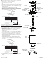
NOTE: Thread locking compound must be applied to all stem threads as noted with symbol
(4) to prevent accidental rotation of fixture during cleaning, relamping, etc.
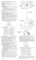
1) Screw center stem onto coupling on top of fixture body..
2) Turn off power.
3) Install canopy mounting screws, finger tight.
4) Apply thread locking compound to threaded pipe from parts bag approximately 1/2” into
stem.
5) Slip canopy then mounting strap over stem(s) assembled to fixture.
6) Apply thread locking compound to threads in ball swivel. Secure in place by threading
a hexnut onto threaded pipe inside ball.
7) Lift mounting strap up against ball swivel, aligning slot in ball with tab in strap. Snap
ball retainer into place. Placing one side of ball retainer in place and then snapping
the other in is suggested.
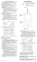
8) Attach assembled fixture/mounting strap to outlet box. Assemble mounting strap to
ceiling with ball slot and tab towards lower portion of slope in ceiling.
(REF: Illustration A)
9) Attach ground wire from outlet box between cupped washer and green ground screw
and thread ground screw into mounting strap. If fixture is provided with ground wire,
connect fixture ground wire to outlet box ground wire with wire connectors (not provided).
Never connect ground wire to black or white power supply wire.
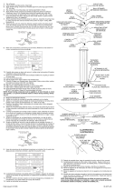
10) Make wire connections (connectors not provided.) Reference chart below for correct
connections and wire accordingly.
11) Carefully slip canopy up stem and secure to ceiling using lockwashers (Canadian
installations only) and ball knobs.
12) Set glass over socket and screw on socket ring.
NOTa: Debe aplicarse un compuesto para el sellado de roscas en todas las roscas de
las varillas indicadas con el símbolo (4) para evitar la rotación accidental del artefacto
durante su limpieza, cambio de bombillas, etc.
1) Atornille el vástago central en el acoplamiento encima del cuerpo del artefacto.
2) Apague la alimentación eléctrica.
3) Instalar los tornillos de montaje del escudete, apretando con los dedos.
4) Aplique un compuesto para el sellado de roscas (suministrado en la bolsa de las
partes) al tubo roscado aproximadamente 1/2” dentro de la varilla.
5) Deslizar el escudete y luego la abrazadera de montaje sobre el (los) vástago(s)
montados al artefacto.
6) Aplique el compuesto para sellar las roscas, a las roscas de la bola de giro. Fije en
su lugar colocando y atornillando una tuerca hexanogal en el tubo roscado dentro de
la esfera.
7) Levantar la abrazadera de montaje contra el pivote a rótula, alineando la muesca
en la rótula con la orejeta en la abrazadera. Instalar rápido el retenedor redondo en
su lugar. Se sugiere colocar un lado del retenedor redondo en el lugar y luego
enganchar el otro.
8) Acoplar la abrazadera de montaje/artefacto ensamblados a la caja de salida. Montar
la abrazadera de montaje al cielorraso con la muesca y orejeta hacia la porción más
baja de la inclinación del cielorraso.
(Ref: Ilustración A)
9) Acoplar el alambre de tierra de la caja de salida entre la arandela cóncava y el
tornillo de tierra verde, y roscar el tornillo de tierra en la abrazadera de montaje.
Si el artefacto está provisto con un alambre de tierra, conectar el alambre de tierra
del artefacto al alambre de tierra de la caja de salida,con los conectores de alambre
(no se proveen). Nunca se debe conectar el alambre de tierra al alambre de alimentación
negro o blanco.
10) Hacer las conexiones de los alambres (conectores no incluidos.) Ver el cuadro más
abajo para las conexiones correctas y alambrar de acuerdo a esto.
11) Cuidadosamente deslizar el escudete arriba en el vástago y asegurar al cielorraso
usando las arandelas de seguridad (Sólo en instalaciones canadienses) y las perillas
redondas.
12) Coloque el vidrio encima de los casquillos y atornille en los anillos del casquillo.
TORNILLO DE TIERRA
VERDE
CONECTOR DE ALAMBRE
(NO SE PROVEE)
TIERRA DE LA
CAJA DE SALIDA
ARANDELA
CONCAVA
TIERRA
ARTEFACTO
Connect Black or
Red Supply Wire to:
Connect
White Supply Wire to:
Black White
*Parallel cord (round & smooth) *Parallel cord (square & ridged)
Clear, Brown, Gold or Black
without tracer
Clear, Brown, Gold or Black
with tracer
Insulated wire (other than green)
with copper conductor
Insulated wire (other than green)
with silver conductor
*Note: When parallel wires (SPT I & SPT II)
are used. The neutral wire is square shaped
or ridged and the other wire will be round in
shape or smooth (see illus.)
Neutral Wire
GREEN GROUND
SCREW
WIRE CONNECTOR
(NOT PROVIDED)
OUTLET BOX
GROUND
CUPPED
WASHER
FIXTURE
GROUND
Connect Black or
Red Supply Wire to:
Connect
White Supply Wire to:
Black White
*Parallel cord (round & smooth) *Parallel cord (square & ridged)
Clear, Brown, Gold or Black
without tracer
Clear, Brown, Gold or Black
with tracer
Insulated wire (other than green)
with copper conductor
Insulated wire (other than green)
with silver conductor
*Note: When parallel wires (SPT I & SPT II)
are used. The neutral wire is square shaped
or ridged and the other wire will be round in
shape or smooth (see illus.)
Neutral Wire
CANOPY
CAPUCHÓN
STEM
VARILLA
GLASS
VIDRIO
Date Issued: 12/12/08 IS-42123-US
BALL RETAINER
RETENEDOR REDONDO
HEXNUT
TUERCA HEXAGONAL
MOUNTING STRAP
ABRAZADERA
DE MONTAJE
THREADED PIPE
TUBO ROSCADO
GREEN GROUND SCREW
TORNILLO VERDE DE
TIERRA
BALL SWIVEL
PIVOTE A ROTULA
BALL KNOB
PERILLA REDONDA
SLOT AND TAB
MUESCA Y OREJETA
SLOPED CEILING
CIELORRASO
INCLINADO
ILLUSTRaTION a
COUPLING
ACOPLAMIENTO
3
SOCKET RING
ANILLO DEL CASQUILLO
FIXTURE BODY
CUERPO DEL
ARTEFACTO
3
3
Transcripción de documentos
NOTE: Thread locking compound must be applied to all stem threads as noted with symbol (4) to prevent accidental rotation of fixture during cleaning, relamping, etc. 1) Screw center stem onto coupling on top of fixture body.. 2) Turn off power. 3) Install canopy mounting screws, finger tight. 4) Apply thread locking compound to threaded pipe from parts bag approximately 1/2” into stem. 5) Slip canopy then mounting strap over stem(s) assembled to fixture. 6) Apply thread locking compound to threads in ball swivel. Secure in place by threading a hexnut onto threaded pipe inside ball. 7) Lift mounting strap up against ball swivel, aligning slot in ball with tab in strap. Snap ball retainer into place. Placing one side of ball retainer in place and then snapping the other in is suggested. 8) Attach assembled fixture/mounting strap to outlet box. Assemble mounting strap to ceiling with ball slot and tab towards lower portion of slope in ceiling. (REF: Illustration A) 9) Attach ground wire from outlet box between cupped washer and green ground screw and thread ground screw into mounting strap. If fixture is provided with ground wire, connect fixture ground wire to outlet box ground wire with wire connectors (not provided). Never connect ground wire to black or white power supply wire. WIRE CONNECTOR (NOT PROVIDED) BALL RETAINER RETENEDOR REDONDO HEXNUT TUERCA HEXAGONAL THREADED PIPE TUBO ROSCADO MOUNTING STRAP ABRAZADERA DE MONTAJE BALL SWIVEL PIVOTE A ROTULA 3 GREEN GROUND SCREW TORNILLO VERDE DE TIERRA FIXTuRE GROuND CANOPY capuchón OuTLET BOX GROuND CuPPED WASHER GREEN GROuND SCREW BALL KNOB PERILLA REDONDA STEM VARILLA 10) Make wire connections (connectors not provided.) Reference chart below for correct connections and wire accordingly. Connect Black or Red Supply Wire to: Connect White Supply Wire to: Black White *Parallel cord (round & smooth) *Parallel cord (square & ridged) Clear, Brown, Gold or Black without tracer Clear, Brown, Gold or Black with tracer Insulated wire (other than green) with copper conductor Insulated wire (other than green) with silver conductor *Note: When parallel wires (SPT I & SPT II) are used. The neutral wire is square shaped or ridged and the other wire will be round in shape or smooth (see illus.) 3 Neutral Wire 11) Carefully slip canopy up stem and secure to ceiling using lockwashers (Canadian installations only) and ball knobs. 12) Set glass over socket and screw on socket ring. Nota: Debe aplicarse un compuesto para el sellado de roscas en todas las roscas de las varillas indicadas con el símbolo (4) para evitar la rotación accidental del artefacto durante su limpieza, cambio de bombillas, etc. 1) Atornille el vástago central en el acoplamiento encima del cuerpo del artefacto. 2) Apague la alimentación eléctrica. 3) Instalar los tornillos de montaje del escudete, apretando con los dedos. 4) Aplique un compuesto para el sellado de roscas (suministrado en la bolsa de las partes) al tubo roscado aproximadamente 1/2” dentro de la varilla. 5) Deslizar el escudete y luego la abrazadera de montaje sobre el (los) vástago(s) montados al artefacto. 6) Aplique el compuesto para sellar las roscas, a las roscas de la bola de giro. Fije en su lugar colocando y atornillando una tuerca hexanogal en el tubo roscado dentro de la esfera. 7) Levantar la abrazadera de montaje contra el pivote a rótula, alineando la muesca en la rótula con la orejeta en la abrazadera. Instalar rápido el retenedor redondo en su lugar. Se sugiere colocar un lado del retenedor redondo en el lugar y luego enganchar el otro. 8) Acoplar la abrazadera de montaje/artefacto ensamblados a la caja de salida. Montar la abrazadera de montaje al cielorraso con la muesca y orejeta hacia la porción más baja de la inclinación del cielorraso. (Ref: Ilustración A) 9) Acoplar el alambre de tierra de la caja de salida entre la arandela cóncava y el tornillo de tierra verde, y roscar el tornillo de tierra en la abrazadera de montaje. Si el artefacto está provisto con un alambre de tierra, conectar el alambre de tierra del artefacto al alambre de tierra de la caja de salida,con los conectores de alambre (no se proveen). Nunca se debe conectar el alambre de tierra al alambre de alimentación negro o blanco. COUPLING ACOPLAMIENTO 3 FIXTURE BODY CUERPO DEL ARTEFACTO GLASS VIDRIO CONECTOR DE ALAMBRE (NO SE PROVEE) TIERRA DE LA CAJA DE SALIDA TIERRA ARTEFACTO ARANDELA CONCAVA SOCKET RING ANILLO DEL CASQUILLO TORNILLO DE TIERRA VERDE 10) Hacer las conexiones de los alambres (conectores no incluidos.) Ver el cuadro más abajo para las conexiones correctas y alambrar de acuerdo a esto. Connect Black or Red Supply Wire to: Connect White Supply Wire to: Black White *Parallel cord (round & smooth) *Parallel cord (square & ridged) Clear, Brown, Gold or Black without tracer Clear, Brown, Gold or Black with tracer Insulated wire (other than green) with copper conductor Insulated wire (other than green) with silver conductor *Note: When parallel wires (SPT I & SPT II) are used. The neutral wire is square shaped or ridged and the other wire will be round in shape or smooth (see illus.) ILLUSTRATION A SLOPED CEILING CIELORRASO INCLINADO SLOT AND TAB MUESCA Y OREJETA Neutral Wire 11) Cuidadosamente deslizar el escudete arriba en el vástago y asegurar al cielorraso usando las arandelas de seguridad (Sólo en instalaciones canadienses) y las perillas redondas. 12) Coloque el vidrio encima de los casquillos y atornille en los anillos del casquillo. Date Issued: 12/12/08 IS-42123-US-
 1
1

Kichler Lighting 42123CH Manual de usuario
- Tipo
- Manual de usuario
en otros idiomas
- English: Kichler Lighting 42123CH User manual
Artículos relacionados
-
 Kichler Lighting 3275NI Manual de usuario
-
 Kichler Lighting 3275NI Guía de instalación
-
 Kichler Lighting 42549CLP Manual de usuario
-
 Kichler Lighting 2655NI Manual de usuario
-
 Kichler Lighting 2640NI Manual de usuario
-
 Kichler Lighting 1672OZ Manual de usuario
-
 Kichler Lighting 3278AP Manual de usuario
-
 Kichler Lighting 2643NI Manual de usuario
-
 Kichler Lighting 2055NI Manual de usuario
-
 Kichler Lighting 2955NI Manual de usuario


