Volkswagen 2004 Golf Manual de usuario
- Categoría
- Motor
- Tipo
- Manual de usuario
Este manual también es adecuado para

P
r
o
t
e
c
t
e
d
b
y
c
o
p
y
r
i
g
h
t
.
C
o
p
y
i
n
g
f
o
r
p
r
i
v
a
t
e
o
r
c
o
m
m
e
r
c
i
a
l
p
u
r
p
o
s
e
s
,
i
n
p
a
r
t
o
r
i
n
w
h
o
l
e
,
i
s
n
o
t
p
e
r
m
i
t
t
e
d
u
n
l
e
s
s
a
u
t
h
o
r
i
s
e
d
b
y
V
o
l
k
s
w
a
g
e
n
A
G
.
V
o
l
k
s
w
a
g
e
n
A
G
d
o
e
s
n
o
t
g
u
a
r
a
n
t
e
e
o
r
a
c
c
e
p
t
a
n
y
l
i
a
b
i
l
i
t
y
w
i
t
h
r
e
s
p
e
c
t
t
o
t
h
e
c
o
r
r
e
c
t
n
e
s
s
o
f
i
n
f
o
r
m
a
t
i
o
n
i
n
t
h
i
s
d
o
c
u
m
e
n
t
.
C
o
p
y
r
i
g
h
t
b
y
V
o
l
k
s
w
a
g
e
n
A
G
.
Workshop Manual
Golf 2004 ➤
Golf Plus 2005 ➤
4-cylinder diesel engine (1.9 l engine)
Engine ID
BJB BKC BRU BLS BXE BXF BXJ
Edition 01.2009
Service
Service Department. Technical Information

P
r
o
t
e
c
t
e
d
b
y
c
o
p
y
r
i
g
h
t
.
C
o
p
y
i
n
g
f
o
r
p
r
i
v
a
t
e
o
r
c
o
m
m
e
r
c
i
a
l
p
u
r
p
o
s
e
s
,
i
n
p
a
r
t
o
r
i
n
w
h
o
l
e
,
i
s
n
o
t
p
e
r
m
i
t
t
e
d
u
n
l
e
s
s
a
u
t
h
o
r
i
s
e
d
b
y
V
o
l
k
s
w
a
g
e
n
A
G
.
V
o
l
k
s
w
a
g
e
n
A
G
d
o
e
s
n
o
t
g
u
a
r
a
n
t
e
e
o
r
a
c
c
e
p
t
a
n
y
l
i
a
b
i
l
i
t
y
w
i
t
h
r
e
s
p
e
c
t
t
o
t
h
e
c
o
r
r
e
c
t
n
e
s
s
o
f
i
n
f
o
r
m
a
t
i
o
n
i
n
t
h
i
s
d
o
c
u
m
e
n
t
.
C
o
p
y
r
i
g
h
t
b
y
V
o
l
k
s
w
a
g
e
n
A
G
.
List of Workshop Manual Repair GroupsList of Workshop Manual
Repair GroupsList of Workshop Manual Repair Groups
Repair Group
00 - Technical data
10 - Removing and installing engine
13 - Crankshaft group
15 - Cylinder head, valve gear
17 - Lubrication
19 - Cooling
20 - Fuel supply system
21 - Turbocharging/supercharging
23 - Mixture preparation - injection
26 - Exhaust system
28 - Glow plug system
Technical information should always be available to the foremen and mechanics, because their
careful and constant adherence to the instructions is essential to ensure vehicle road-worthiness and
safety. In addition, the normal basic safety precautions for working on motor vehicles must, as a
matter of course, be observed.
Service
All rights reserved.
No reproduction without prior agreement from publisher.
Copyright © 2010 Volkswagen AG, Wolfsburg K0059000420

P
r
o
t
e
c
t
e
d
b
y
c
o
p
y
r
i
g
h
t
.
C
o
p
y
i
n
g
f
o
r
p
r
i
v
a
t
e
o
r
c
o
m
m
e
r
c
i
a
l
p
u
r
p
o
s
e
s
,
i
n
p
a
r
t
o
r
i
n
w
h
o
l
e
,
i
s
n
o
t
p
e
r
m
i
t
t
e
d
u
n
l
e
s
s
a
u
t
h
o
r
i
s
e
d
b
y
V
o
l
k
s
w
a
g
e
n
A
G
.
V
o
l
k
s
w
a
g
e
n
A
G
d
o
e
s
n
o
t
g
u
a
r
a
n
t
e
e
o
r
a
c
c
e
p
t
a
n
y
l
i
a
b
i
l
i
t
y
w
i
t
h
r
e
s
p
e
c
t
t
o
t
h
e
c
o
r
r
e
c
t
n
e
s
s
o
f
i
n
f
o
r
m
a
t
i
o
n
i
n
t
h
i
s
d
o
c
u
m
e
n
t
.
C
o
p
y
r
i
g
h
t
b
y
V
o
l
k
s
w
a
g
e
n
A
G
.
Contents
00 - Technical data . . . . . . . . . . . . . . . . . . . . . . . . . . . . . . . . . . . . . . . . . . . . . . . . . . . . 1
1 Technical data . . . . . . . . . . . . . . . . . . . . . . . . . . . . . . . . . . . . . . . . . . . . . . . . . . . . . . . . . . 1
1.1 Engine number . . . . . . . . . . . . . . . . . . . . . . . . . . . . . . . . . . . . . . . . . . . . . . . . . . . . . . . . . . 1
1.2 Engine data . . . . . . . . . . . . . . . . . . . . . . . . . . . . . . . . . . . . . . . . . . . . . . . . . . . . . . . . . . . . 1
10 - Removing and installing engine . . . . . . . . . . . . . . . . . . . . . . . . . . . . . . . . . . . . . . 2
1 Removing and installing engine . . . . . . . . . . . . . . . . . . . . . . . . . . . . . . . . . . . . . . . . . . . . . . 2
1.1 Removing engine . . . . . . . . . . . . . . . . . . . . . . . . . . . . . . . . . . . . . . . . . . . . . . . . . . . . . . . . 2
1.2 Securing engine to assembly stand . . . . . . . . . . . . . . . . . . . . . . . . . . . . . . . . . . . . . . . . . . 7
1.3 Notes on installing . . . . . . . . . . . . . . . . . . . . . . . . . . . . . . . . . . . . . . . . . . . . . . . . . . . . . . . . 7
1.4 Assembly mountings . . . . . . . . . . . . . . . . . . . . . . . . . . . . . . . . . . . . . . . . . . . . . . . . . . . . . . 10
13 - Crankshaft group . . . . . . . . . . . . . . . . . . . . . . . . . . . . . . . . . . . . . . . . . . . . . . . . . . 12
1 Dismantling and assembling engine . . . . . . . . . . . . . . . . . . . . . . . . . . . . . . . . . . . . . . . . . . 12
1.1 Assembly overview - poly V-belt drive . . . . . . . . . . . . . . . . . . . . . . . . . . . . . . . . . . . . . . . . 12
1.2 Removing and installing poly V-belt . . . . . . . . . . . . . . . . . . . . . . . . . . . . . . . . . . . . . . . . . . 13
1.3 Assembly overview - toothed belt drive . . . . . . . . . . . . . . . . . . . . . . . . . . . . . . . . . . . . . . . . 15
1.4 Assembly overview - crankcase . . . . . . . . . . . . . . . . . . . . . . . . . . . . . . . . . . . . . . . . . . . . . . 19
2 Removing and installing sealing flange and flywheel . . . . . . . . . . . . . . . . . . . . . . . . . . . . . . 20
2.1 Assembly overview - sealing flanges and flywheel . . . . . . . . . . . . . . . . . . . . . . . . . . . . . . 20
2.2 Renewing crankshaft oil seal - pulley end . . . . . . . . . . . . . . . . . . . . . . . . . . . . . . . . . . . . . . 21
2.3 Removing and installing sealing flange - pulley end . . . . . . . . . . . . . . . . . . . . . . . . . . . . . . 23
2.4 Renewing crankshaft sealing flange - flywheel end . . . . . . . . . . . . . . . . . . . . . . . . . . . . . . 25
2.5 Removing and installing engine speed sender G28 . . . . . . . . . . . . . . . . . . . . . . . . . . . . . . 31
3 Crankshaft . . . . . . . . . . . . . . . . . . . . . . . . . . . . . . . . . . . . . . . . . . . . . . . . . . . . . . . . . . . . . . 33
3.1 Assembly overview - crankshaft . . . . . . . . . . . . . . . . . . . . . . . . . . . . . . . . . . . . . . . . . . . . . . 33
3.2 Crankshaft dimensions . . . . . . . . . . . . . . . . . . . . . . . . . . . . . . . . . . . . . . . . . . . . . . . . . . . . 38
4 Pistons and conrods . . . . . . . . . . . . . . . . . . . . . . . . . . . . . . . . . . . . . . . . . . . . . . . . . . . . . . 39
4.1 Assembly overview - pistons and conrods . . . . . . . . . . . . . . . . . . . . . . . . . . . . . . . . . . . . . . 39
4.2 Separating new conrod . . . . . . . . . . . . . . . . . . . . . . . . . . . . . . . . . . . . . . . . . . . . . . . . . . . . 40
4.3 Checking piston projection at TDC . . . . . . . . . . . . . . . . . . . . . . . . . . . . . . . . . . . . . . . . . . . . 41
4.4 Piston and cylinder dimensions . . . . . . . . . . . . . . . . . . . . . . . . . . . . . . . . . . . . . . . . . . . . . . 42
4.5 Piston rings, cylinder bore and piston installation position . . . . . . . . . . . . . . . . . . . . . . . . . . 42
15 - Cylinder head, valve gear . . . . . . . . . . . . . . . . . . . . . . . . . . . . . . . . . . . . . . . . . . 44
1 Cylinder head . . . . . . . . . . . . . . . . . . . . . . . . . . . . . . . . . . . . . . . . . . . . . . . . . . . . . . . . . . . . 44
1.1 Assembly overview - cylinder head . . . . . . . . . . . . . . . . . . . . . . . . . . . . . . . . . . . . . . . . . . 45
1.2 Removing and installing cylinder head cover . . . . . . . . . . . . . . . . . . . . . . . . . . . . . . . . . . . . 48
1.3 Removing, installing and tensioning toothed belts . . . . . . . . . . . . . . . . . . . . . . . . . . . . . . . . 50
1.4 Removing and installing cylinder head . . . . . . . . . . . . . . . . . . . . . . . . . . . . . . . . . . . . . . . . 67
1.5 Checking compression . . . . . . . . . . . . . . . . . . . . . . . . . . . . . . . . . . . . . . . . . . . . . . . . . . . . 71
2 Valve gear . . . . . . . . . . . . . . . . . . . . . . . . . . . . . . . . . . . . . . . . . . . . . . . . . . . . . . . . . . . . . . 74
2.1 Assembly overview - valve gear . . . . . . . . . . . . . . . . . . . . . . . . . . . . . . . . . . . . . . . . . . . . . . 74
2.2 Checking valve guides . . . . . . . . . . . . . . . . . . . . . . . . . . . . . . . . . . . . . . . . . . . . . . . . . . . . 76
2.3 Renewing valve stem seals . . . . . . . . . . . . . . . . . . . . . . . . . . . . . . . . . . . . . . . . . . . . . . . . 78
2.4 Removing and installing camshaft . . . . . . . . . . . . . . . . . . . . . . . . . . . . . . . . . . . . . . . . . . . . 80
2.5 Removing and installing camshaft oil seal . . . . . . . . . . . . . . . . . . . . . . . . . . . . . . . . . . . . . . 84
17 - Lubrication . . . . . . . . . . . . . . . . . . . . . . . . . . . . . . . . . . . . . . . . . . . . . . . . . . . . . . 86
1 Engine oil . . . . . . . . . . . . . . . . . . . . . . . . . . . . . . . . . . . . . . . . . . . . . . . . . . . . . . . . . . . . . . 86
1.1 Oil capacities . . . . . . . . . . . . . . . . . . . . . . . . . . . . . . . . . . . . . . . . . . . . . . . . . . . . . . . . . . . . 86
1.2 Checking engine oil level . . . . . . . . . . . . . . . . . . . . . . . . . . . . . . . . . . . . . . . . . . . . . . . . . . 86
Golf 2004 ➤ , Golf Plus 2005 ➤
4-cylinder diesel engine (1.9 l engine) - Edition 01.2009
Contents i

P
r
o
t
e
c
t
e
d
b
y
c
o
p
y
r
i
g
h
t
.
C
o
p
y
i
n
g
f
o
r
p
r
i
v
a
t
e
o
r
c
o
m
m
e
r
c
i
a
l
p
u
r
p
o
s
e
s
,
i
n
p
a
r
t
o
r
i
n
w
h
o
l
e
,
i
s
n
o
t
p
e
r
m
i
t
t
e
d
u
n
l
e
s
s
a
u
t
h
o
r
i
s
e
d
b
y
V
o
l
k
s
w
a
g
e
n
A
G
.
V
o
l
k
s
w
a
g
e
n
A
G
d
o
e
s
n
o
t
g
u
a
r
a
n
t
e
e
o
r
a
c
c
e
p
t
a
n
y
l
i
a
b
i
l
i
t
y
w
i
t
h
r
e
s
p
e
c
t
t
o
t
h
e
c
o
r
r
e
c
t
n
e
s
s
o
f
i
n
f
o
r
m
a
t
i
o
n
i
n
t
h
i
s
d
o
c
u
m
e
n
t
.
C
o
p
y
r
i
g
h
t
b
y
V
o
l
k
s
w
a
g
e
n
A
G
.
2 Parts of lubrication system . . . . . . . . . . . . . . . . . . . . . . . . . . . . . . . . . . . . . . . . . . . . . . . . . . 87
2.1 Assembly overview - oil pump, sump . . . . . . . . . . . . . . . . . . . . . . . . . . . . . . . . . . . . . . . . . . 87
2.2 Removing and installing sump . . . . . . . . . . . . . . . . . . . . . . . . . . . . . . . . . . . . . . . . . . . . . . 88
3 Oil filter bracket, oil pressure, engine oil cooler and oil supply line . . . . . . . . . . . . . . . . . . 92
3.1 Assembly overview - oil filter bracket and engine oil cooler . . . . . . . . . . . . . . . . . . . . . . . . 92
3.2 Checking oil pressure and oil pressure switch . . . . . . . . . . . . . . . . . . . . . . . . . . . . . . . . . . 93
3.3 Assembly overview - oil supply line to turbocharger . . . . . . . . . . . . . . . . . . . . . . . . . . . . . . 94
3.4 Removing and installing oil supply line to turbocharger . . . . . . . . . . . . . . . . . . . . . . . . . . . . 95
19 - Cooling . . . . . . . . . . . . . . . . . . . . . . . . . . . . . . . . . . . . . . . . . . . . . . . . . . . . . . . . . . 97
1 Parts of cooling system . . . . . . . . . . . . . . . . . . . . . . . . . . . . . . . . . . . . . . . . . . . . . . . . . . . . 97
1.1 Parts of cooling system, body side . . . . . . . . . . . . . . . . . . . . . . . . . . . . . . . . . . . . . . . . . . . . 98
1.2 Parts of cooling system, engine side . . . . . . . . . . . . . . . . . . . . . . . . . . . . . . . . . . . . . . . . . . 99
1.3 Coolant hose schematic diagram . . . . . . . . . . . . . . . . . . . . . . . . . . . . . . . . . . . . . . . . . . . . 101
1.4 Draining and filling with coolant . . . . . . . . . . . . . . . . . . . . . . . . . . . . . . . . . . . . . . . . . . . . . . 102
1.5 Removing and installing radiator . . . . . . . . . . . . . . . . . . . . . . . . . . . . . . . . . . . . . . . . . . . . 105
1.6 Removing and installing coolant pump . . . . . . . . . . . . . . . . . . . . . . . . . . . . . . . . . . . . . . . . 106
1.7 Removing and installing thermostat . . . . . . . . . . . . . . . . . . . . . . . . . . . . . . . . . . . . . . . . . . 108
1.8 Checking cooling system for leaks . . . . . . . . . . . . . . . . . . . . . . . . . . . . . . . . . . . . . . . . . . . . 110
1.9 Checking engine oil cooler for leaks . . . . . . . . . . . . . . . . . . . . . . . . . . . . . . . . . . . . . . . . . . 112
20 - Fuel supply system . . . . . . . . . . . . . . . . . . . . . . . . . . . . . . . . . . . . . . . . . . . . . . . . 114
1 Safety precautions when working on fuel supply system . . . . . . . . . . . . . . . . . . . . . . . . . . 114
2 Rules for cleanliness . . . . . . . . . . . . . . . . . . . . . . . . . . . . . . . . . . . . . . . . . . . . . . . . . . . . . . 115
3 Fuel tank, vehicles with front-wheel drive . . . . . . . . . . . . . . . . . . . . . . . . . . . . . . . . . . . . . . 116
3.1 Assembly overview - fuel tank . . . . . . . . . . . . . . . . . . . . . . . . . . . . . . . . . . . . . . . . . . . . . . 116
3.2 Emptying fuel tank . . . . . . . . . . . . . . . . . . . . . . . . . . . . . . . . . . . . . . . . . . . . . . . . . . . . . . . . 117
3.3 Removing and installing fuel tank . . . . . . . . . . . . . . . . . . . . . . . . . . . . . . . . . . . . . . . . . . . . 121
3.4 Removing and installing fuel delivery unit . . . . . . . . . . . . . . . . . . . . . . . . . . . . . . . . . . . . . . 123
3.5 Removing and installing fuel gauge sender . . . . . . . . . . . . . . . . . . . . . . . . . . . . . . . . . . . . 124
3.6 Checking fuel pump . . . . . . . . . . . . . . . . . . . . . . . . . . . . . . . . . . . . . . . . . . . . . . . . . . . . . . 125
4 Fuel tank, vehicles with four-wheel drive . . . . . . . . . . . . . . . . . . . . . . . . . . . . . . . . . . . . . . 127
4.1 Assembly overview - fuel tank . . . . . . . . . . . . . . . . . . . . . . . . . . . . . . . . . . . . . . . . . . . . . . 127
4.2 Emptying fuel tank . . . . . . . . . . . . . . . . . . . . . . . . . . . . . . . . . . . . . . . . . . . . . . . . . . . . . . . . 128
4.3 Removing and installing fuel tank . . . . . . . . . . . . . . . . . . . . . . . . . . . . . . . . . . . . . . . . . . . . 132
4.4 Removing and installing fuel gauge sender 2 G169 . . . . . . . . . . . . . . . . . . . . . . . . . . . . . . 135
4.5 Removing and installing suction-jet pump . . . . . . . . . . . . . . . . . . . . . . . . . . . . . . . . . . . . . . 137
4.6 Checking fuel pump . . . . . . . . . . . . . . . . . . . . . . . . . . . . . . . . . . . . . . . . . . . . . . . . . . . . . . 138
5 Repairing fuel supply system . . . . . . . . . . . . . . . . . . . . . . . . . . . . . . . . . . . . . . . . . . . . . . . . 140
5.1 Assembly overview - fuel filter . . . . . . . . . . . . . . . . . . . . . . . . . . . . . . . . . . . . . . . . . . . . . . 140
5.2 Removing and installing fuel cooler . . . . . . . . . . . . . . . . . . . . . . . . . . . . . . . . . . . . . . . . . . 141
5.3 Assembly overview - accelerator mechanism . . . . . . . . . . . . . . . . . . . . . . . . . . . . . . . . . . 142
5.4 Checking tandem pump . . . . . . . . . . . . . . . . . . . . . . . . . . . . . . . . . . . . . . . . . . . . . . . . . . . . 143
5.5 Removing and installing tandem pump . . . . . . . . . . . . . . . . . . . . . . . . . . . . . . . . . . . . . . . . 147
21 - Turbocharging/supercharging . . . . . . . . . . . . . . . . . . . . . . . . . . . . . . . . . . . . . . . . 151
1 Charge air system with turbocharger . . . . . . . . . . . . . . . . . . . . . . . . . . . . . . . . . . . . . . . . . . 151
1.1 Safety precautions . . . . . . . . . . . . . . . . . . . . . . . . . . . . . . . . . . . . . . . . . . . . . . . . . . . . . . . . 151
1.2 Rules for cleanliness . . . . . . . . . . . . . . . . . . . . . . . . . . . . . . . . . . . . . . . . . . . . . . . . . . . . . . 151
1.3 Assembly overview - turbocharger . . . . . . . . . . . . . . . . . . . . . . . . . . . . . . . . . . . . . . . . . . . . 152
1.4 Removing and installing turbocharger . . . . . . . . . . . . . . . . . . . . . . . . . . . . . . . . . . . . . . . . 156
1.5 Assembly overview - parts of charge air cooling . . . . . . . . . . . . . . . . . . . . . . . . . . . . . . . . 158
1.6 Hose connections . . . . . . . . . . . . . . . . . . . . . . . . . . . . . . . . . . . . . . . . . . . . . . . . . . . . . . . . 161
1.7 Checking charge air system for leaks . . . . . . . . . . . . . . . . . . . . . . . . . . . . . . . . . . . . . . . . 162
1.8 Vacuum hose schematic diagram . . . . . . . . . . . . . . . . . . . . . . . . . . . . . . . . . . . . . . . . . . . . 164
Golf 2004 ➤ , Golf Plus 2005 ➤
4-cylinder diesel engine (1.9 l engine) - Edition 01.2009
ii Contents

P
r
o
t
e
c
t
e
d
b
y
c
o
p
y
r
i
g
h
t
.
C
o
p
y
i
n
g
f
o
r
p
r
i
v
a
t
e
o
r
c
o
m
m
e
r
c
i
a
l
p
u
r
p
o
s
e
s
,
i
n
p
a
r
t
o
r
i
n
w
h
o
l
e
,
i
s
n
o
t
p
e
r
m
i
t
t
e
d
u
n
l
e
s
s
a
u
t
h
o
r
i
s
e
d
b
y
V
o
l
k
s
w
a
g
e
n
A
G
.
V
o
l
k
s
w
a
g
e
n
A
G
d
o
e
s
n
o
t
g
u
a
r
a
n
t
e
e
o
r
a
c
c
e
p
t
a
n
y
l
i
a
b
i
l
i
t
y
w
i
t
h
r
e
s
p
e
c
t
t
o
t
h
e
c
o
r
r
e
c
t
n
e
s
s
o
f
i
n
f
o
r
m
a
t
i
o
n
i
n
t
h
i
s
d
o
c
u
m
e
n
t
.
C
o
p
y
r
i
g
h
t
b
y
V
o
l
k
s
w
a
g
e
n
A
G
.
23 - Mixture preparation - injection . . . . . . . . . . . . . . . . . . . . . . . . . . . . . . . . . . . . . . . . 166
1 Diesel direct injection system . . . . . . . . . . . . . . . . . . . . . . . . . . . . . . . . . . . . . . . . . . . . . . . . 166
1.1 Safety precautions . . . . . . . . . . . . . . . . . . . . . . . . . . . . . . . . . . . . . . . . . . . . . . . . . . . . . . . . 166
1.2 Rules for cleanliness . . . . . . . . . . . . . . . . . . . . . . . . . . . . . . . . . . . . . . . . . . . . . . . . . . . . . . 167
1.3 Assembly overview - unit injector . . . . . . . . . . . . . . . . . . . . . . . . . . . . . . . . . . . . . . . . . . . . 167
1.4 Removing and installing unit injector . . . . . . . . . . . . . . . . . . . . . . . . . . . . . . . . . . . . . . . . . . 169
1.5 Adjusting non-contact gap of unit injectors . . . . . . . . . . . . . . . . . . . . . . . . . . . . . . . . . . . . . . 171
1.6 Removing and installing O-rings for unit injector . . . . . . . . . . . . . . . . . . . . . . . . . . . . . . . . 172
1.7 Assembly overview - intake manifold . . . . . . . . . . . . . . . . . . . . . . . . . . . . . . . . . . . . . . . . . . 174
1.8 Cleaning the intake manifold flap support, Engine code BLS and BXJ . . . . . . . . . . . . . . . . 176
1.9 Assembly overview - air filter . . . . . . . . . . . . . . . . . . . . . . . . . . . . . . . . . . . . . . . . . . . . . . . . 177
2 Engine control unit . . . . . . . . . . . . . . . . . . . . . . . . . . . . . . . . . . . . . . . . . . . . . . . . . . . . . . . . 178
2.1 Reading and erasing engine control unit fault memory . . . . . . . . . . . . . . . . . . . . . . . . . . . . 178
2.2 Adapting functions and components . . . . . . . . . . . . . . . . . . . . . . . . . . . . . . . . . . . . . . . . . . 179
2.3 Removing and installing engine control unit, Golf . . . . . . . . . . . . . . . . . . . . . . . . . . . . . . . . 180
2.4 Removing and installing anti-theft engine control unit, Golf . . . . . . . . . . . . . . . . . . . . . . . . 180
2.5 Removing and installing engine control unit, Golf Plus . . . . . . . . . . . . . . . . . . . . . . . . . . . . 183
2.6 Removing and installing anti-theft engine control unit, Golf Plus . . . . . . . . . . . . . . . . . . . . 183
26 - Exhaust system . . . . . . . . . . . . . . . . . . . . . . . . . . . . . . . . . . . . . . . . . . . . . . . . . . 186
1 Exhaust system . . . . . . . . . . . . . . . . . . . . . . . . . . . . . . . . . . . . . . . . . . . . . . . . . . . . . . . . . . 186
1.1 Assembly overview - front exhaust pipe with catalytic converter . . . . . . . . . . . . . . . . . . . . 186
1.2 Assembly overview - front exhaust pipe with particulate filter . . . . . . . . . . . . . . . . . . . . . . 187
1.3 Assembly overview - silencer with mountings (vehicles with front wheel drive) . . . . . . . . . . 189
1.4 Assembly overview - silencer with mountings (vehicles with four-wheel drive) . . . . . . . . . . 191
1.5 Aligning exhaust system free of stress . . . . . . . . . . . . . . . . . . . . . . . . . . . . . . . . . . . . . . . . 192
2 Exhaust gas recirculation system . . . . . . . . . . . . . . . . . . . . . . . . . . . . . . . . . . . . . . . . . . . . 193
2.1 Assembly overview - parts of exhaust gas recirculation . . . . . . . . . . . . . . . . . . . . . . . . . . . . 193
28 - Glow plug system . . . . . . . . . . . . . . . . . . . . . . . . . . . . . . . . . . . . . . . . . . . . . . . . . . 198
1 Checking glow plug system . . . . . . . . . . . . . . . . . . . . . . . . . . . . . . . . . . . . . . . . . . . . . . . . 198
1.1 Removing, installing and checking glow plugs . . . . . . . . . . . . . . . . . . . . . . . . . . . . . . . . . . 198
1.2 Characteristics of ceramic glow plugs . . . . . . . . . . . . . . . . . . . . . . . . . . . . . . . . . . . . . . . . 199
1.3 Removing, installing and checking ceramic glow plugs . . . . . . . . . . . . . . . . . . . . . . . . . . . . 200
Golf 2004 ➤ , Golf Plus 2005 ➤
4-cylinder diesel engine (1.9 l engine) - Edition 01.2009
Contents iii

P
r
o
t
e
c
t
e
d
b
y
c
o
p
y
r
i
g
h
t
.
C
o
p
y
i
n
g
f
o
r
p
r
i
v
a
t
e
o
r
c
o
m
m
e
r
c
i
a
l
p
u
r
p
o
s
e
s
,
i
n
p
a
r
t
o
r
i
n
w
h
o
l
e
,
i
s
n
o
t
p
e
r
m
i
t
t
e
d
u
n
l
e
s
s
a
u
t
h
o
r
i
s
e
d
b
y
V
o
l
k
s
w
a
g
e
n
A
G
.
V
o
l
k
s
w
a
g
e
n
A
G
d
o
e
s
n
o
t
g
u
a
r
a
n
t
e
e
o
r
a
c
c
e
p
t
a
n
y
l
i
a
b
i
l
i
t
y
w
i
t
h
r
e
s
p
e
c
t
t
o
t
h
e
c
o
r
r
e
c
t
n
e
s
s
o
f
i
n
f
o
r
m
a
t
i
o
n
i
n
t
h
i
s
d
o
c
u
m
e
n
t
.
C
o
p
y
r
i
g
h
t
b
y
V
o
l
k
s
w
a
g
e
n
A
G
.
Golf 2004 ➤ , Golf Plus 2005 ➤
4-cylinder diesel engine (1.9 l engine) - Edition 01.2009
iv Contents

P
r
o
t
e
c
t
e
d
b
y
c
o
p
y
r
i
g
h
t
.
C
o
p
y
i
n
g
f
o
r
p
r
i
v
a
t
e
o
r
c
o
m
m
e
r
c
i
a
l
p
u
r
p
o
s
e
s
,
i
n
p
a
r
t
o
r
i
n
w
h
o
l
e
,
i
s
n
o
t
p
e
r
m
i
t
t
e
d
u
n
l
e
s
s
a
u
t
h
o
r
i
s
e
d
b
y
V
o
l
k
s
w
a
g
e
n
A
G
.
V
o
l
k
s
w
a
g
e
n
A
G
d
o
e
s
n
o
t
g
u
a
r
a
n
t
e
e
o
r
a
c
c
e
p
t
a
n
y
l
i
a
b
i
l
i
t
y
w
i
t
h
r
e
s
p
e
c
t
t
o
t
h
e
c
o
r
r
e
c
t
n
e
s
s
o
f
i
n
f
o
r
m
a
t
i
o
n
i
n
t
h
i
s
d
o
c
u
m
e
n
t
.
C
o
p
y
r
i
g
h
t
b
y
V
o
l
k
s
w
a
g
e
n
A
G
.
00 – Technical data
1 Technical data
Engine number ⇒ page 1
Engine data ⇒ page 1
1.1 Engine number
The engine number (“code letters” and “serial number”) can be
found at the joint between engine and gearbox.
Additionally there is a sticker on the toothed belt guard with “en‐
gine code” and “serial number”.
The engine code is also included on the vehicle data sticker.
1.2 Engine data
Engine code BJB BKC BRU BLS BXE BXF BXJ
Manufactured 10.03 ▸ 10.03 ▸ 04.04 ▸ 02.06 ▸ 03.06 03.06 11.07
Emissions fulfil EU3
standard
EU4
standard
EU4
standard
EU4
standard
EU4
standard
EU4
standard
EU4
standard
Capacity l 1.9 1.9 1.9 1.9 1.9 1.9 1.9
Output kW at
rpm
77/
4000
77/
4000
66/
4000
77/
4000
77/
4000
66/
4000
66/
4000
Torque Nm at
rpm
250/
1900
250/
1900
210/
1800...250
0
250/
1900
250/
1900
210/
1800
210/
1800...250
0
Bore ∅ mm 79.5 79.5 79.5 79.5 79.5 79.5 79.5
Stroke mm 95.5 95.5 95.5 95.5 95.5 95.5 95.5
Valves per cylinder 2 2 2 2 2 2 2
Compression ratio 19.0 19.0 19.0 18.5 18.5 19.0 19.0
Fuel accord‐
ing to
DIN EN
590
DIN EN
590
DIN EN
590
DIN EN
590
DIN EN
590
DIN EN
590
DIN EN
590
Firing order
1-3-4-2 1-3-4-2 1-3-4-2 1-3-4-2 1-3-4-2 1-3-4-2 1-3-4-2
Catalytic converter yes yes yes yes yes yes yes
Exhaust gas recircu‐
lation
yes yes yes yes yes yes yes
Turbocharging/super‐
charging
yes yes yes yes yes yes yes
Charge air cooler yes yes yes yes yes yes yes
Particulate filter no no no yes no no no
Golf 2004 ➤ , Golf Plus 2005 ➤
4-cylinder diesel engine (1.9 l engine) - Edition 01.2009
1. Technical data 1

P
r
o
t
e
c
t
e
d
b
y
c
o
p
y
r
i
g
h
t
.
C
o
p
y
i
n
g
f
o
r
p
r
i
v
a
t
e
o
r
c
o
m
m
e
r
c
i
a
l
p
u
r
p
o
s
e
s
,
i
n
p
a
r
t
o
r
i
n
w
h
o
l
e
,
i
s
n
o
t
p
e
r
m
i
t
t
e
d
u
n
l
e
s
s
a
u
t
h
o
r
i
s
e
d
b
y
V
o
l
k
s
w
a
g
e
n
A
G
.
V
o
l
k
s
w
a
g
e
n
A
G
d
o
e
s
n
o
t
g
u
a
r
a
n
t
e
e
o
r
a
c
c
e
p
t
a
n
y
l
i
a
b
i
l
i
t
y
w
i
t
h
r
e
s
p
e
c
t
t
o
t
h
e
c
o
r
r
e
c
t
n
e
s
s
o
f
i
n
f
o
r
m
a
t
i
o
n
i
n
t
h
i
s
d
o
c
u
m
e
n
t
.
C
o
p
y
r
i
g
h
t
b
y
V
o
l
k
s
w
a
g
e
n
A
G
.
10 – Removing and installing engine
1 Removing and installing engine
Removing engine ⇒ page 2
Securing engine to assembly stand ⇒ page 7
Notes on installing ⇒ page 7 .
Assembly mountings ⇒ page 10 .
1.1 Removing engine
Special tools and workshop
equipment required
♦ Lifting tackle -2024 A-
♦ Engine bracket -T10012-
♦ Support clamp -VW 313-
♦ Engine and gearbox sup‐
port -VW 540-
♦ Workshop crane -V.A.G
1202 A-
♦ Drip tray -V.A.G 1306-
Golf 2004 ➤ , Golf Plus 2005 ➤
4-cylinder diesel engine (1.9 l engine) - Edition 01.2009
2 Rep. Gr.10 - Removing and installing engine

P
r
o
t
e
c
t
e
d
b
y
c
o
p
y
r
i
g
h
t
.
C
o
p
y
i
n
g
f
o
r
p
r
i
v
a
t
e
o
r
c
o
m
m
e
r
c
i
a
l
p
u
r
p
o
s
e
s
,
i
n
p
a
r
t
o
r
i
n
w
h
o
l
e
,
i
s
n
o
t
p
e
r
m
i
t
t
e
d
u
n
l
e
s
s
a
u
t
h
o
r
i
s
e
d
b
y
V
o
l
k
s
w
a
g
e
n
A
G
.
V
o
l
k
s
w
a
g
e
n
A
G
d
o
e
s
n
o
t
g
u
a
r
a
n
t
e
e
o
r
a
c
c
e
p
t
a
n
y
l
i
a
b
i
l
i
t
y
w
i
t
h
r
e
s
p
e
c
t
t
o
t
h
e
c
o
r
r
e
c
t
n
e
s
s
o
f
i
n
f
o
r
m
a
t
i
o
n
i
n
t
h
i
s
d
o
c
u
m
e
n
t
.
C
o
p
y
r
i
g
h
t
b
y
V
o
l
k
s
w
a
g
e
n
A
G
.
♦ Torque wrench -V.A.G
1331-
♦ Torque wrench -V.A.G
1332-
♦ Engine and gearbox jack -
V.A.G 1383 A-
♦ Spring-type clip pliers -VAS
5024-
♦ Stepladder -VAS 5085-
♦ Guide rods -T10093-
♦ Cable ties
Note
♦
Before carrying out further work, disconnect battery earth
strap. First check whether a coded radio is fitted. Obtain anti-
theft coding first if necessary.
♦
The engine is removed downwards together with the gearbox.
♦
All cable ties which are opened or cut through when engine is
removed must be replaced in the same position when engine
is installed.
Golf 2004 ➤ , Golf Plus 2005 ➤
4-cylinder diesel engine (1.9 l engine) - Edition 01.2009
1. Removing and installing engine 3

P
r
o
t
e
c
t
e
d
b
y
c
o
p
y
r
i
g
h
t
.
C
o
p
y
i
n
g
f
o
r
p
r
i
v
a
t
e
o
r
c
o
m
m
e
r
c
i
a
l
p
u
r
p
o
s
e
s
,
i
n
p
a
r
t
o
r
i
n
w
h
o
l
e
,
i
s
n
o
t
p
e
r
m
i
t
t
e
d
u
n
l
e
s
s
a
u
t
h
o
r
i
s
e
d
b
y
V
o
l
k
s
w
a
g
e
n
A
G
.
V
o
l
k
s
w
a
g
e
n
A
G
d
o
e
s
n
o
t
g
u
a
r
a
n
t
e
e
o
r
a
c
c
e
p
t
a
n
y
l
i
a
b
i
l
i
t
y
w
i
t
h
r
e
s
p
e
c
t
t
o
t
h
e
c
o
r
r
e
c
t
n
e
s
s
o
f
i
n
f
o
r
m
a
t
i
o
n
i
n
t
h
i
s
d
o
c
u
m
e
n
t
.
C
o
p
y
r
i
g
h
t
b
y
V
o
l
k
s
w
a
g
e
n
A
G
.
WARNING
When doing any repair work, especially in the engine compart‐
ment, pay attention to the following due to the cramped condi‐
tions:
♦ Route all the various lines (e.g. for fuel, hydraulics, acti‐
vated charcoal filter system, coolant, refrigerant, brake
fluid and vacuum) and electrical wiring in their original po‐
sitions.
♦ Ensure that there is sufficient clearance to all moving or
hot components.
Procedure
– With ignition switched off, disconnect earth strap from battery.
One-piece engine cover
For one-piece engine cover, pull engine cover abruptly upwards
at front and right -arrows A-, then pull forwards out of rear fas‐
tening -arrow B-.
Two-piece engine cover
For two-piece engine cover, first pull outer engine cover abruptly
upwards at -arrows-, then pull inner engine cover abruptly up‐
wards at -arrows-.
– Remove plenum chamber bulkhead. ⇒ General body repairs,
exterior; Rep. Gr. 50 ; Body - front, plenum chamber bulk‐
head .
– Remove air filter housing with air mass meter and connecting
pipe.
Golf 2004 ➤ , Golf Plus 2005 ➤
4-cylinder diesel engine (1.9 l engine) - Edition 01.2009
4 Rep. Gr.10 - Removing and installing engine

P
r
o
t
e
c
t
e
d
b
y
c
o
p
y
r
i
g
h
t
.
C
o
p
y
i
n
g
f
o
r
p
r
i
v
a
t
e
o
r
c
o
m
m
e
r
c
i
a
l
p
u
r
p
o
s
e
s
,
i
n
p
a
r
t
o
r
i
n
w
h
o
l
e
,
i
s
n
o
t
p
e
r
m
i
t
t
e
d
u
n
l
e
s
s
a
u
t
h
o
r
i
s
e
d
b
y
V
o
l
k
s
w
a
g
e
n
A
G
.
V
o
l
k
s
w
a
g
e
n
A
G
d
o
e
s
n
o
t
g
u
a
r
a
n
t
e
e
o
r
a
c
c
e
p
t
a
n
y
l
i
a
b
i
l
i
t
y
w
i
t
h
r
e
s
p
e
c
t
t
o
t
h
e
c
o
r
r
e
c
t
n
e
s
s
o
f
i
n
f
o
r
m
a
t
i
o
n
i
n
t
h
i
s
d
o
c
u
m
e
n
t
.
C
o
p
y
r
i
g
h
t
b
y
V
o
l
k
s
w
a
g
e
n
A
G
.
– Remove bolt -arrow A- and pull air filter housing upwards out
of mounting.
– Remove battery and battery tray.
– Disconnect fuel supply and return lines as well as coolant line
on cylinder head.
WARNING
♦ The fuel and the fuel lines in the fuel system can become
very hot (danger of scalding)!
♦ The fuel system is also under pressure! Before opening
the system, place cloths around the connections. Then
carefully loosen connection to release the pressure!
♦ Wear eye and hand protection when performing any type
of repair work on the fuel system!
– Remove insulation tray ⇒ General body repairs, exterior; Rep.
Gr. 50 ; Body - front; Assembly overview
– Bring lock carrier into service position ⇒ General body repairs,
exterior; Rep. Gr. 50 ; Body - front; Lock carrier - service po‐
sition .
– Drain coolant ⇒ page 102 .
Vehicles with air conditioner
Note
To prevent damage to condenser or to refrigerant lines/hoses,
ensure that the lines and hoses are not stretched, kinked or bent.
To facilitate removing and installing engine without opening re‐
frigerant circuit:
– Remove poly V-belt ⇒ page 13 .
– Remove air conditioner compressor ⇒ Heating, air condition‐
ing; Rep. Gr. 87 ; Removing and installing compressor brack‐
et .
– Secure air conditioner compressor to lock carrier so that re‐
frigerant lines are free of stress.
– Remove alternator ⇒ Electrical system; Rep. Gr. 27 ; Re‐
moving and installing alternator and poly V-belt .
Continuation for all vehicles
– Remove connecting pipes between charge air cooler and en‐
gine.
– Unbolt left and right-hand drive shafts from gearbox ⇒ Run‐
ning gear, axles, steering; Rep. Gr. 40 ; Removing and
installing drive shaft .
– Remove front exhaust pipe ⇒ page 186 .
– Release connectors on engine control unit and pull them off.
Golf 2004 ➤ , Golf Plus 2005 ➤
4-cylinder diesel engine (1.9 l engine) - Edition 01.2009
1. Removing and installing engine 5

P
r
o
t
e
c
t
e
d
b
y
c
o
p
y
r
i
g
h
t
.
C
o
p
y
i
n
g
f
o
r
p
r
i
v
a
t
e
o
r
c
o
m
m
e
r
c
i
a
l
p
u
r
p
o
s
e
s
,
i
n
p
a
r
t
o
r
i
n
w
h
o
l
e
,
i
s
n
o
t
p
e
r
m
i
t
t
e
d
u
n
l
e
s
s
a
u
t
h
o
r
i
s
e
d
b
y
V
o
l
k
s
w
a
g
e
n
A
G
.
V
o
l
k
s
w
a
g
e
n
A
G
d
o
e
s
n
o
t
g
u
a
r
a
n
t
e
e
o
r
a
c
c
e
p
t
a
n
y
l
i
a
b
i
l
i
t
y
w
i
t
h
r
e
s
p
e
c
t
t
o
t
h
e
c
o
r
r
e
c
t
n
e
s
s
o
f
i
n
f
o
r
m
a
t
i
o
n
i
n
t
h
i
s
d
o
c
u
m
e
n
t
.
C
o
p
y
r
i
g
h
t
b
y
V
o
l
k
s
w
a
g
e
n
A
G
.
– Open all cable guide fasteners -arrows-.
– Remove wiring harness from cable guide on longitudinal mem‐
ber and lay to side on engine.
– Pull off or disconnect all other electrical connections from en‐
gine and gearbox as necessary and lay to side.
– Separate all connecting, coolant, vacuum and intake hoses
from engine.
Vehicles with manual gearbox
– Remove slave cylinder for hydraulic clutch. ⇒ 6-speed manual
gearbox 02S; Rep. Gr. 30 ; Repairing clutch mechanism; As‐
sembly overview - hydraulics .
– Unbolt gear selector mechanism from gearbox. ⇒ 6-speed
manual gearbox 02S; Rep. Gr. 34 ; Repairing selector mech‐
anism .
Vehicles with four-wheel drive:
– Remove selector mechanism from gearbox ⇒ 6-speed man‐
ual gearbox 02Q, four-wheel drive; Rep. Gr. 34 ; Repairing
selector mechanism .
– Separate pressure line for hydraulic clutch control.
– Remove front propshaft ⇒ Final drive 02D, 0AV; Rep. Gr. 39 ;
Assembly overview - repairing propshaft .
Continuation for all vehicles:
– Unbolt pendulum support -arrows-.
Vehicles with particulate filter
– Remove subframe ⇒ Running gear, axles, steering; Rep. Gr.
40 ; Removing and installing subframe .
– Remove right drive shaft ⇒ Running gear, axles, steering;
Rep. Gr. 40 ; Removing and installing drive shafts .
– Remove steering box ⇒ Running gear, axles, steering; Rep.
Gr. 48 ; Removing and installing steering box .
Continuation for all vehicles:
– Insert engine bracket -T10012- in engine and gearbox jack -
V.A.G 1383 A- .
Note
Support pins must be secured to engine bracket -T10012- as
shown.
– Fit engine bracket -T10012- to cylinder block with M10 x 25/
8.8 bolt and tighten to approx. 40 Nm.
– Raise engine and gearbox slightly using engine and gearbox
jack -V.A.G 1383 A- .
Golf 2004 ➤ , Golf Plus 2005 ➤
4-cylinder diesel engine (1.9 l engine) - Edition 01.2009
6 Rep. Gr.10 - Removing and installing engine

P
r
o
t
e
c
t
e
d
b
y
c
o
p
y
r
i
g
h
t
.
C
o
p
y
i
n
g
f
o
r
p
r
i
v
a
t
e
o
r
c
o
m
m
e
r
c
i
a
l
p
u
r
p
o
s
e
s
,
i
n
p
a
r
t
o
r
i
n
w
h
o
l
e
,
i
s
n
o
t
p
e
r
m
i
t
t
e
d
u
n
l
e
s
s
a
u
t
h
o
r
i
s
e
d
b
y
V
o
l
k
s
w
a
g
e
n
A
G
.
V
o
l
k
s
w
a
g
e
n
A
G
d
o
e
s
n
o
t
g
u
a
r
a
n
t
e
e
o
r
a
c
c
e
p
t
a
n
y
l
i
a
b
i
l
i
t
y
w
i
t
h
r
e
s
p
e
c
t
t
o
t
h
e
c
o
r
r
e
c
t
n
e
s
s
o
f
i
n
f
o
r
m
a
t
i
o
n
i
n
t
h
i
s
d
o
c
u
m
e
n
t
.
C
o
p
y
r
i
g
h
t
b
y
V
o
l
k
s
w
a
g
e
n
A
G
.
– Unbolt assembly mounting on engine side from engine bracket
-arrows-.
Note
To remove securing bolts, use stepladder -VAS 5085- .
– Unbolt assembly mounting on gearbox side from gearbox
bracket -arrows-.
– Carefully lower engine with gearbox.
Note
Engine with gearbox must be guided carefully when lowered to
prevent damage to bodywork.
1.2 Securing engine to assembly stand
When working on the engine, secure it to support clamp -VW 313-
of the assembly stand using engine and gearbox support -VW
540- .
Procedure
– Disconnect gearbox.
– Attach lifting tackle -2024 A- as shown and raise engine out of
engine and gearbox jack -V.A.G 1383 A- using workshop hoist
-V.A.G 1202 A- .
Pulley end: 2nd hole in hook rail at position 1
Flywheel end: 4th hole in hook at position 8
WARNING
The hooks and locating pins must be secured with locking pins.
Note
♦
The positions marked 1...4 on the bar must be towards the
pulley end.
♦
The holes in the hook rails are counted up from the hook.
– Secure engine on support clamp -VW 313- using engine and
gearbox jack -VW 540- .
1.3 Notes on installing
Installation is carried out in the reverse order. When installing,
note the following:
Golf 2004 ➤ , Golf Plus 2005 ➤
4-cylinder diesel engine (1.9 l engine) - Edition 01.2009
1. Removing and installing engine 7

P
r
o
t
e
c
t
e
d
b
y
c
o
p
y
r
i
g
h
t
.
C
o
p
y
i
n
g
f
o
r
p
r
i
v
a
t
e
o
r
c
o
m
m
e
r
c
i
a
l
p
u
r
p
o
s
e
s
,
i
n
p
a
r
t
o
r
i
n
w
h
o
l
e
,
i
s
n
o
t
p
e
r
m
i
t
t
e
d
u
n
l
e
s
s
a
u
t
h
o
r
i
s
e
d
b
y
V
o
l
k
s
w
a
g
e
n
A
G
.
V
o
l
k
s
w
a
g
e
n
A
G
d
o
e
s
n
o
t
g
u
a
r
a
n
t
e
e
o
r
a
c
c
e
p
t
a
n
y
l
i
a
b
i
l
i
t
y
w
i
t
h
r
e
s
p
e
c
t
t
o
t
h
e
c
o
r
r
e
c
t
n
e
s
s
o
f
i
n
f
o
r
m
a
t
i
o
n
i
n
t
h
i
s
d
o
c
u
m
e
n
t
.
C
o
p
y
r
i
g
h
t
b
y
V
o
l
k
s
w
a
g
e
n
A
G
.
– Check clutch release bearing for wear and renew if necessary.
– Lubricate splines of input shaft lightly with G 000 100.
– Check whether dowel sleeves for centring engine and gearbox
are in cylinder block and install if necessary.
When installing engine, ensure correct position of assembly
mountings:
– On belt pulley side, ensure that there is a distance -a- of at
least 10 mm between engine support and right longitudinal
member.
– The side surface of the engine support -2- should be located
parallel to the support arm -1-. Dimension -x- must be identical
at top and bottom.
Note
Distance -a- = 10 mm can also be checked with a metal rod of
suitable size, or similar.
Golf 2004 ➤ , Golf Plus 2005 ➤
4-cylinder diesel engine (1.9 l engine) - Edition 01.2009
8 Rep. Gr.10 - Removing and installing engine

P
r
o
t
e
c
t
e
d
b
y
c
o
p
y
r
i
g
h
t
.
C
o
p
y
i
n
g
f
o
r
p
r
i
v
a
t
e
o
r
c
o
m
m
e
r
c
i
a
l
p
u
r
p
o
s
e
s
,
i
n
p
a
r
t
o
r
i
n
w
h
o
l
e
,
i
s
n
o
t
p
e
r
m
i
t
t
e
d
u
n
l
e
s
s
a
u
t
h
o
r
i
s
e
d
b
y
V
o
l
k
s
w
a
g
e
n
A
G
.
V
o
l
k
s
w
a
g
e
n
A
G
d
o
e
s
n
o
t
g
u
a
r
a
n
t
e
e
o
r
a
c
c
e
p
t
a
n
y
l
i
a
b
i
l
i
t
y
w
i
t
h
r
e
s
p
e
c
t
t
o
t
h
e
c
o
r
r
e
c
t
n
e
s
s
o
f
i
n
f
o
r
m
a
t
i
o
n
i
n
t
h
i
s
d
o
c
u
m
e
n
t
.
C
o
p
y
r
i
g
h
t
b
y
V
o
l
k
s
w
a
g
e
n
A
G
.
– Ensure that the edges of the support arm on the gearbox as‐
sembly mounting -2- and gearbox support -1- are parallel.
Dimension -x- must be identical at top and bottom.
Note
♦
Torque specifications for assembly mounting ⇒ page 10 .
♦
Electrical connections and routing. ⇒ Electrical system; Rep.
Gr. 97
– Install pendulum support.
– Install drive shafts ⇒ Running gear, axles, steering; Rep. Gr.
40 ; Removing and installing drive shafts .
– Install front exhaust pipe ⇒ page 186 .
Vehicles with manual gearbox
– Install slave cylinder for hydraulic clutch ⇒ 6-speed manual
gearbox 02S; Rep. Gr. 30 ; Repairing clutch mechanism; As‐
sembly overview - hydraulics .
– Remove selector mechanism from gearbox ⇒ 6-speed man‐
ual gearbox 02S; Rep. Gr. 34 ; Repairing selector mecha‐
nism .
Vehicles with four-wheel drive:
– Install selector mechanism on gearbox ⇒ 6-speed manual
gearbox 02Q, four-wheel drive; Rep. Gr. 34 ; Repairing se‐
lector mechanism .
– Install pressure line for hydraulic clutch control.
– Install front propshaft ⇒ Final drive 02D, 0AV; Rep. Gr. 39 ;
Assembly overview - repairing propshaft .
Continuation for all vehicles:
– On vehicles with particulate filter install subframe ⇒ Running
gear, axles, steering; Rep. Gr. 40
– Install alternator ⇒ Electrical system; Rep. Gr. 27 ; Removing
and installing alternator and poly V- belt .
– Install air conditioner compressor ⇒ Heating, air conditioning;
Rep. Gr. 87 ; Removing and installing compressor bracket.
– Install poly V-belt ⇒ page 13 .
– Install insulation tray ⇒ General body repairs, exterior; Rep.
Gr. 50 ; Body - front; Assembly overview.
– Install engine control unit ⇒ page 178 .
– Install plenum chamber bulkhead ⇒ General body repairs,
exterior; Rep. Gr. 50 ; Body - front; Plenum chamber bulk‐
head .
– Fill cooling system with coolant ⇒ page 102 .
– Carry out road test and then read fault memory ⇒ page 178 .
Golf 2004 ➤ , Golf Plus 2005 ➤
4-cylinder diesel engine (1.9 l engine) - Edition 01.2009
1. Removing and installing engine 9

P
r
o
t
e
c
t
e
d
b
y
c
o
p
y
r
i
g
h
t
.
C
o
p
y
i
n
g
f
o
r
p
r
i
v
a
t
e
o
r
c
o
m
m
e
r
c
i
a
l
p
u
r
p
o
s
e
s
,
i
n
p
a
r
t
o
r
i
n
w
h
o
l
e
,
i
s
n
o
t
p
e
r
m
i
t
t
e
d
u
n
l
e
s
s
a
u
t
h
o
r
i
s
e
d
b
y
V
o
l
k
s
w
a
g
e
n
A
G
.
V
o
l
k
s
w
a
g
e
n
A
G
d
o
e
s
n
o
t
g
u
a
r
a
n
t
e
e
o
r
a
c
c
e
p
t
a
n
y
l
i
a
b
i
l
i
t
y
w
i
t
h
r
e
s
p
e
c
t
t
o
t
h
e
c
o
r
r
e
c
t
n
e
s
s
o
f
i
n
f
o
r
m
a
t
i
o
n
i
n
t
h
i
s
d
o
c
u
m
e
n
t
.
C
o
p
y
r
i
g
h
t
b
y
V
o
l
k
s
w
a
g
e
n
A
G
.
Specified torques
Threaded connection
Specified torque
Bolts, nuts M6 10 Nm
M8 20 Nm
M10 45 Nm
M12 60 Nm
1.4 Assembly mountings
Engine assembly mounting
A = 20 Nm + 90° (1/4 turn) further
1)
B = 40 Nm + 90° (1/4 turn) further
1)
C = 60 Nm + 90° (1/4 turn) further
1)
1)
Renew
Gearbox assembly mounting
A = 40 Nm + 90° (1/4 turn) further
1)
B = 60 Nm + 90° (1/4 turn) further
1)
1)
Renew
Golf 2004 ➤ , Golf Plus 2005 ➤
4-cylinder diesel engine (1.9 l engine) - Edition 01.2009
10 Rep. Gr.10 - Removing and installing engine

P
r
o
t
e
c
t
e
d
b
y
c
o
p
y
r
i
g
h
t
.
C
o
p
y
i
n
g
f
o
r
p
r
i
v
a
t
e
o
r
c
o
m
m
e
r
c
i
a
l
p
u
r
p
o
s
e
s
,
i
n
p
a
r
t
o
r
i
n
w
h
o
l
e
,
i
s
n
o
t
p
e
r
m
i
t
t
e
d
u
n
l
e
s
s
a
u
t
h
o
r
i
s
e
d
b
y
V
o
l
k
s
w
a
g
e
n
A
G
.
V
o
l
k
s
w
a
g
e
n
A
G
d
o
e
s
n
o
t
g
u
a
r
a
n
t
e
e
o
r
a
c
c
e
p
t
a
n
y
l
i
a
b
i
l
i
t
y
w
i
t
h
r
e
s
p
e
c
t
t
o
t
h
e
c
o
r
r
e
c
t
n
e
s
s
o
f
i
n
f
o
r
m
a
t
i
o
n
i
n
t
h
i
s
d
o
c
u
m
e
n
t
.
C
o
p
y
r
i
g
h
t
b
y
V
o
l
k
s
w
a
g
e
n
A
G
.
Pendulum support
Always note the size and strength class of bolt. Different specified
torques are valid.
Caution
From model year 08, in manual gearboxes 02Q Heli Coil in‐
serts are installed in the threaded connections to pendulum
support. Difference ⇒ Rep. Gr. 34
For these and all other gearboxes bolts with strength class 10.9
must be used.
If Heli Coil inserts are not fitted in manual gearboxes 02Q, use
bolts with strength class 8.8 and the specified torques.
Bolt -A-
M10 x 35 strength class 8.8: turn 40 Nm + 90° further
M10 x 35 strength class 10.9: turn 50 Nm + 90° further
Always renew after removing
Bolt -B-
M10 x 75 strength class 8.8: turn 40 Nm + 90° further
M10 x 75 strength class 10.9: turn 50 Nm + 90° further
Always renew after removing
Bolt -C-
M14 x 1.5 x 70
100 Nm + turn 90° further
Tighten only if pendulum support is bolted to gearbox
Always renew after removing
Golf 2004 ➤ , Golf Plus 2005 ➤
4-cylinder diesel engine (1.9 l engine) - Edition 01.2009
1. Removing and installing engine 11

P
r
o
t
e
c
t
e
d
b
y
c
o
p
y
r
i
g
h
t
.
C
o
p
y
i
n
g
f
o
r
p
r
i
v
a
t
e
o
r
c
o
m
m
e
r
c
i
a
l
p
u
r
p
o
s
e
s
,
i
n
p
a
r
t
o
r
i
n
w
h
o
l
e
,
i
s
n
o
t
p
e
r
m
i
t
t
e
d
u
n
l
e
s
s
a
u
t
h
o
r
i
s
e
d
b
y
V
o
l
k
s
w
a
g
e
n
A
G
.
V
o
l
k
s
w
a
g
e
n
A
G
d
o
e
s
n
o
t
g
u
a
r
a
n
t
e
e
o
r
a
c
c
e
p
t
a
n
y
l
i
a
b
i
l
i
t
y
w
i
t
h
r
e
s
p
e
c
t
t
o
t
h
e
c
o
r
r
e
c
t
n
e
s
s
o
f
i
n
f
o
r
m
a
t
i
o
n
i
n
t
h
i
s
d
o
c
u
m
e
n
t
.
C
o
p
y
r
i
g
h
t
b
y
V
o
l
k
s
w
a
g
e
n
A
G
.
13 – Crankshaft group
1 Dismantling and assembling engine
Assembly overview - poly V-belt drive ⇒ page 12
Removing and installing poly V-belt ⇒ page 13
Assembly overview - toothed belt drive ⇒ page 15
Assembly overview - crankcase ⇒ page 19
Note
If large quantities of metal particles or other deposits (caused, for
example, by partial seizure of the crankshaft or conrod bearings)
are found in the engine oil when making repairs, clean the oil
passages thoroughly and renew the engine oil cooler in order to
prevent further damage from occurring later.
1.1 Assembly overview - poly V-belt drive
1 - Belt pulley and vibration
damper
❑ Can only be installed in
one position, holes are
offset.
2 - 25 Nm
3 - Alternator
4 - Bracket
❑ For alternator and air
conditioner compressor.
5 - Poly V-belt tensioning ele‐
ment
❑ Swing with ring spanner
to slacken poly V-belt.
6 - 25 Nm
7 - Air conditioner compressor
8 - 25 Nm
9 - Dowel sleeves
10 - Poly V-belt
❑ Mark direction of rota‐
tion before removing.
❑ Check for wear.
❑ Do not kink.
❑ Removing and installing
⇒ page 13 .
Golf 2004 ➤ , Golf Plus 2005 ➤
4-cylinder diesel engine (1.9 l engine) - Edition 01.2009
12 Rep. Gr.13 - Crankshaft group

P
r
o
t
e
c
t
e
d
b
y
c
o
p
y
r
i
g
h
t
.
C
o
p
y
i
n
g
f
o
r
p
r
i
v
a
t
e
o
r
c
o
m
m
e
r
c
i
a
l
p
u
r
p
o
s
e
s
,
i
n
p
a
r
t
o
r
i
n
w
h
o
l
e
,
i
s
n
o
t
p
e
r
m
i
t
t
e
d
u
n
l
e
s
s
a
u
t
h
o
r
i
s
e
d
b
y
V
o
l
k
s
w
a
g
e
n
A
G
.
V
o
l
k
s
w
a
g
e
n
A
G
d
o
e
s
n
o
t
g
u
a
r
a
n
t
e
e
o
r
a
c
c
e
p
t
a
n
y
l
i
a
b
i
l
i
t
y
w
i
t
h
r
e
s
p
e
c
t
t
o
t
h
e
c
o
r
r
e
c
t
n
e
s
s
o
f
i
n
f
o
r
m
a
t
i
o
n
i
n
t
h
i
s
d
o
c
u
m
e
n
t
.
C
o
p
y
r
i
g
h
t
b
y
V
o
l
k
s
w
a
g
e
n
A
G
.
1.2 Removing and installing poly V-belt
Special tools and workshop equipment required
♦ Locking pin -T10060 A-
♦ 16 mm open-end spanner -T 10241-
1.2.1 Removing poly V-belt
– Remove insulation tray. ⇒ General body repairs, exterior;
Rep. Gr. 50 ; Body - front; Assembly overview .
– Pull fuel filter out of bracket and lay it with hoses to side.
– Mark direction of rotation of poly V-belt.
– Swing tensioning element in direction of arrow to remove ten‐
sion from poly V-belt.
The open-end spanner 16 mm -T 10241- is particularly well suited
to relieve tension.
Golf 2004 ➤ , Golf Plus 2005 ➤
4-cylinder diesel engine (1.9 l engine) - Edition 01.2009
1. Dismantling and assembling engine 13

P
r
o
t
e
c
t
e
d
b
y
c
o
p
y
r
i
g
h
t
.
C
o
p
y
i
n
g
f
o
r
p
r
i
v
a
t
e
o
r
c
o
m
m
e
r
c
i
a
l
p
u
r
p
o
s
e
s
,
i
n
p
a
r
t
o
r
i
n
w
h
o
l
e
,
i
s
n
o
t
p
e
r
m
i
t
t
e
d
u
n
l
e
s
s
a
u
t
h
o
r
i
s
e
d
b
y
V
o
l
k
s
w
a
g
e
n
A
G
.
V
o
l
k
s
w
a
g
e
n
A
G
d
o
e
s
n
o
t
g
u
a
r
a
n
t
e
e
o
r
a
c
c
e
p
t
a
n
y
l
i
a
b
i
l
i
t
y
w
i
t
h
r
e
s
p
e
c
t
t
o
t
h
e
c
o
r
r
e
c
t
n
e
s
s
o
f
i
n
f
o
r
m
a
t
i
o
n
i
n
t
h
i
s
d
o
c
u
m
e
n
t
.
C
o
p
y
r
i
g
h
t
b
y
V
o
l
k
s
w
a
g
e
n
A
G
.
– Lock tensioning element in position with locking pin -T10060
A- .
– Remove poly V-belt.
1.2.2 Installing poly V-belt
– Installation is carried out in the reverse sequence of removal.
Note
♦
Before installing poly V-belt, ensure that all ancillaries (alter‐
nator, air conditioner compressor) are secured tightly.
♦
When fitting poly V-belt, check direction of belt rotation and
ensure proper seating of belt in pulleys.
♦
Lastly, place poly V-belt over alternator.
After completing repairs always:
– Start engine and check belt running.
Belt drive without air conditioner compressor
Belt drive with air conditioner compressor
Golf 2004 ➤ , Golf Plus 2005 ➤
4-cylinder diesel engine (1.9 l engine) - Edition 01.2009
14 Rep. Gr.13 - Crankshaft group

P
r
o
t
e
c
t
e
d
b
y
c
o
p
y
r
i
g
h
t
.
C
o
p
y
i
n
g
f
o
r
p
r
i
v
a
t
e
o
r
c
o
m
m
e
r
c
i
a
l
p
u
r
p
o
s
e
s
,
i
n
p
a
r
t
o
r
i
n
w
h
o
l
e
,
i
s
n
o
t
p
e
r
m
i
t
t
e
d
u
n
l
e
s
s
a
u
t
h
o
r
i
s
e
d
b
y
V
o
l
k
s
w
a
g
e
n
A
G
.
V
o
l
k
s
w
a
g
e
n
A
G
d
o
e
s
n
o
t
g
u
a
r
a
n
t
e
e
o
r
a
c
c
e
p
t
a
n
y
l
i
a
b
i
l
i
t
y
w
i
t
h
r
e
s
p
e
c
t
t
o
t
h
e
c
o
r
r
e
c
t
n
e
s
s
o
f
i
n
f
o
r
m
a
t
i
o
n
i
n
t
h
i
s
d
o
c
u
m
e
n
t
.
C
o
p
y
r
i
g
h
t
b
y
V
o
l
k
s
w
a
g
e
n
A
G
.
1.3 Assembly overview - toothed belt drive
1 - Toothed belt guard upper
part
2 - 100 Nm
3 - 25 Nm
4 - Camshaft pulley
5 - Hub
❑ With sender wheel
❑ Use counterhold tool -
T10051- to loosen and
tighten.
❑ To remove, use puller -
T10052-
❑ Removing and installing
⇒ page 80 , removing
and installing camshaft.
6 - 10 Nm
❑ Renew
7 - Stud
❑ 15 Nm
8 - Rear toothed belt guard
9 - 25 Nm
10 - Sealing grommet
❑ Renew if damaged.
11 - 20 Nm +
1
/
8
turn (45°) fur‐
ther
12 - Tensioning roller
❑ Remove engine support
in order to remove and
install ⇒ page 16 .
13 - 20 Nm
14 - Idler roller
15 - Coolant pump
❑ Removing and installing ⇒ page 106 .
16 - Crankshaft toothed belt pulley
17 - 120 Nm +
1
/
4
turn (90°) further
❑ Renew
❑ Use counterhold tool -3099- to loosen and tighten.
❑ Do not additionally oil or grease thread and shoulder.
❑ Turning further can be done in several stages.
18 - 15 Nm
19 - Toothed belt guard lower part
20 - Belt pulley and vibration damper
❑ Can only be installed in one position, holes are offset.
21 - 10 Nm +
1
/
4
turn (90°) further
❑ Renew
Golf 2004 ➤ , Golf Plus 2005 ➤
4-cylinder diesel engine (1.9 l engine) - Edition 01.2009
1. Dismantling and assembling engine 15

P
r
o
t
e
c
t
e
d
b
y
c
o
p
y
r
i
g
h
t
.
C
o
p
y
i
n
g
f
o
r
p
r
i
v
a
t
e
o
r
c
o
m
m
e
r
c
i
a
l
p
u
r
p
o
s
e
s
,
i
n
p
a
r
t
o
r
i
n
w
h
o
l
e
,
i
s
n
o
t
p
e
r
m
i
t
t
e
d
u
n
l
e
s
s
a
u
t
h
o
r
i
s
e
d
b
y
V
o
l
k
s
w
a
g
e
n
A
G
.
V
o
l
k
s
w
a
g
e
n
A
G
d
o
e
s
n
o
t
g
u
a
r
a
n
t
e
e
o
r
a
c
c
e
p
t
a
n
y
l
i
a
b
i
l
i
t
y
w
i
t
h
r
e
s
p
e
c
t
t
o
t
h
e
c
o
r
r
e
c
t
n
e
s
s
o
f
i
n
f
o
r
m
a
t
i
o
n
i
n
t
h
i
s
d
o
c
u
m
e
n
t
.
C
o
p
y
r
i
g
h
t
b
y
V
o
l
k
s
w
a
g
e
n
A
G
.
22 - Cover
23 - Toothed belt
❑ Mark direction of rotation before removing.
❑ Check for wear.
❑ Do not kink.
❑ Removing, installing and tensioning ⇒ page 50 .
24 - 40 Nm +
1
/
2
turn (180°) further
❑ Renew
25 - Toothed belt guard centre part
26 - Engine bracket
1.3.1 Removing and installing engine support
Special tools and workshop equipment required
♦ Support bracket -10 - 222 A-
♦ Torque wrench -V.A.G 1331-
– Remove engine cover.
– To do this, pull engine cover upwards abruptly at front and right
-arrows A- and then pull forwards out of rear fastening
-arrow B-.
Two-piece engine cover
For two-piece engine cover, first pull outer engine cover abruptly
upwards at -arrows-, then pull inner engine cover abruptly up‐
wards at -arrows-.
Golf 2004 ➤ , Golf Plus 2005 ➤
4-cylinder diesel engine (1.9 l engine) - Edition 01.2009
16 Rep. Gr.13 - Crankshaft group

P
r
o
t
e
c
t
e
d
b
y
c
o
p
y
r
i
g
h
t
.
C
o
p
y
i
n
g
f
o
r
p
r
i
v
a
t
e
o
r
c
o
m
m
e
r
c
i
a
l
p
u
r
p
o
s
e
s
,
i
n
p
a
r
t
o
r
i
n
w
h
o
l
e
,
i
s
n
o
t
p
e
r
m
i
t
t
e
d
u
n
l
e
s
s
a
u
t
h
o
r
i
s
e
d
b
y
V
o
l
k
s
w
a
g
e
n
A
G
.
V
o
l
k
s
w
a
g
e
n
A
G
d
o
e
s
n
o
t
g
u
a
r
a
n
t
e
e
o
r
a
c
c
e
p
t
a
n
y
l
i
a
b
i
l
i
t
y
w
i
t
h
r
e
s
p
e
c
t
t
o
t
h
e
c
o
r
r
e
c
t
n
e
s
s
o
f
i
n
f
o
r
m
a
t
i
o
n
i
n
t
h
i
s
d
o
c
u
m
e
n
t
.
C
o
p
y
r
i
g
h
t
b
y
V
o
l
k
s
w
a
g
e
n
A
G
.
– Separate push-on connectors of fuel lines -arrows-.
Note
♦
Do this by pressing in catch of push-on connectors.
♦
Ensure that no fuel escapes (use a cloth).
– Lay fuel filter with hoses to side.
– Disconnect coolant hose from top of expansion tank.
– Remove expansion tank and lay it to side.
– Remove charge air pipe between charge air cooler and turbo‐
charger.
– Carefully cover or seal open ends.
Golf, Golf Plus and Touran:
– Fit engine support bracket -10-222A- with adapters -10-222A/
13- and take up weight of engine in installation position.
– Remove securing bolts from assembly mounting/engine sup‐
port -arrows- and remove complete assembly mounting.
Note
♦
The assembly mounting may only be removed if the engine is
supported with support bracket 10-222A!
♦
The engine support must only be loosened when the assembly
mounting has been removed.
WARNING
When raising and lowering engine using support bracket
-10-222A- , ensure that no components or hoses are damaged
or torn off.
– Remove noise insulation tray ⇒ General body repairs, exteri‐
or; Rep. Gr. 50 ; Body - front; Assembly overview - noise
insulation .
– Remove front right wheel housing liner.
Golf 2004 ➤ , Golf Plus 2005 ➤
4-cylinder diesel engine (1.9 l engine) - Edition 01.2009
1. Dismantling and assembling engine 17

P
r
o
t
e
c
t
e
d
b
y
c
o
p
y
r
i
g
h
t
.
C
o
p
y
i
n
g
f
o
r
p
r
i
v
a
t
e
o
r
c
o
m
m
e
r
c
i
a
l
p
u
r
p
o
s
e
s
,
i
n
p
a
r
t
o
r
i
n
w
h
o
l
e
,
i
s
n
o
t
p
e
r
m
i
t
t
e
d
u
n
l
e
s
s
a
u
t
h
o
r
i
s
e
d
b
y
V
o
l
k
s
w
a
g
e
n
A
G
.
V
o
l
k
s
w
a
g
e
n
A
G
d
o
e
s
n
o
t
g
u
a
r
a
n
t
e
e
o
r
a
c
c
e
p
t
a
n
y
l
i
a
b
i
l
i
t
y
w
i
t
h
r
e
s
p
e
c
t
t
o
t
h
e
c
o
r
r
e
c
t
n
e
s
s
o
f
i
n
f
o
r
m
a
t
i
o
n
i
n
t
h
i
s
d
o
c
u
m
e
n
t
.
C
o
p
y
r
i
g
h
t
b
y
V
o
l
k
s
w
a
g
e
n
A
G
.
– Raise engine with support bracket -10-222A- until both upper
bolts of engine support can be loosened and removed.
– Lower engine with support bracket -10-222A- until lower bolt
can be loosened and removed.
– Remove engine support upwards.
Installing
– Position engine support from above on cylinder block.
– Insert new bolts and tighten hand-tight.
Caution
The tightening sequence and specified torques for the engine
support securing bolts must always be followed. Otherwise the
engine support can be stressed and it can break.
– Tighten bolts for engine support in the sequence shown
-1…3- to 40 Nm +
1
/
2
turn (180 °) further. To do this, raise or
lower engine using support bracket -10 - 222 A- .
I : Engine support with less clearance to engine
II: Engine support with greater clearance to engine
Note
Before installing assembly mounting, tighten all engine support
bolts to prescribed torque.
– Install assembly mounting between engine and body, renew
securing bolts ⇒ page 10 .
– Bolt engine assembly mounting to engine support -arrows- by
bringing contact surfaces together using support bracket
-10-222A- . Specified torque: 60 Nm + 90° (1/4 turn) further.
Further assembly is basically the reverse of the dismantling se‐
quence. In the process, note the following:
♦ Ensure that fuel hose connections are tight.
♦ Do not interchange supply line and return line (return line blue
or with blue marking, supply line black).
♦ When installing charge air pipes, ensure that locking lugs en‐
gage correctly.
– Install wheel housing liner.
– Install noise insulation tray ⇒ General body repairs, exterior;
Rep. Gr. 50 ; Body - front; Assembly overview - noise insula‐
tion
Golf 2004 ➤ , Golf Plus 2005 ➤
4-cylinder diesel engine (1.9 l engine) - Edition 01.2009
18 Rep. Gr.13 - Crankshaft group

P
r
o
t
e
c
t
e
d
b
y
c
o
p
y
r
i
g
h
t
.
C
o
p
y
i
n
g
f
o
r
p
r
i
v
a
t
e
o
r
c
o
m
m
e
r
c
i
a
l
p
u
r
p
o
s
e
s
,
i
n
p
a
r
t
o
r
i
n
w
h
o
l
e
,
i
s
n
o
t
p
e
r
m
i
t
t
e
d
u
n
l
e
s
s
a
u
t
h
o
r
i
s
e
d
b
y
V
o
l
k
s
w
a
g
e
n
A
G
.
V
o
l
k
s
w
a
g
e
n
A
G
d
o
e
s
n
o
t
g
u
a
r
a
n
t
e
e
o
r
a
c
c
e
p
t
a
n
y
l
i
a
b
i
l
i
t
y
w
i
t
h
r
e
s
p
e
c
t
t
o
t
h
e
c
o
r
r
e
c
t
n
e
s
s
o
f
i
n
f
o
r
m
a
t
i
o
n
i
n
t
h
i
s
d
o
c
u
m
e
n
t
.
C
o
p
y
r
i
g
h
t
b
y
V
o
l
k
s
w
a
g
e
n
A
G
.
1.4 Assembly overview - crankcase
1 - Cylinder block
❑ Removing and installing
sealing flange and fly‐
wheel ⇒ page 20 .
❑ Removing and installing
crankshaft ⇒ page 33
❑ Dismantling and assem‐
bling pistons and con‐
rods ⇒ page 33
2 - Gasket
❑ Renew
3 - Oil filter bracket
❑ Dismantling and assem‐
bling ⇒ page 92 .
4 - 15 Nm +
1
/
4
turn (90°) fur‐
ther
❑ Renew
❑ First fit upper left and
lower right bolts and
then tighten all four bolts
diagonally.
5 - Bracket
6 - 20 Nm
7 - Connection
❑ For thermostat.
8 - 15 Nm
9 - O-ring
❑ Renew
10 - Thermostat
❑ Removing and installing
⇒ page 108 .
❑ Observe installation position ⇒ page 108 , removing and installing thermostat.
❑ Check: Heat thermostat in water
❑ Opening begins at approx. 85 °C
❑ Ends at approx. 105 °C
❑ Opening lift at least 7 mm.
11 - Hexagon bolt
❑ Tightening sequence and torque specifications ⇒ Heating, air conditioning; Rep. Gr. 87 ; Removing and
installing compressor bracket .
12 - Bracket
❑ For alternator, if air conditioner compressor is fitted
13 - Poly V-belt tensioning element
14 - 25 Nm
15 - Sump
❑ Clean sealing surface before fitting.
❑ Install with silicone sealant -D 176 404 A2- .
16 - 15 Nm
Golf 2004 ➤ , Golf Plus 2005 ➤
4-cylinder diesel engine (1.9 l engine) - Edition 01.2009
1. Dismantling and assembling engine 19

P
r
o
t
e
c
t
e
d
b
y
c
o
p
y
r
i
g
h
t
.
C
o
p
y
i
n
g
f
o
r
p
r
i
v
a
t
e
o
r
c
o
m
m
e
r
c
i
a
l
p
u
r
p
o
s
e
s
,
i
n
p
a
r
t
o
r
i
n
w
h
o
l
e
,
i
s
n
o
t
p
e
r
m
i
t
t
e
d
u
n
l
e
s
s
a
u
t
h
o
r
i
s
e
d
b
y
V
o
l
k
s
w
a
g
e
n
A
G
.
V
o
l
k
s
w
a
g
e
n
A
G
d
o
e
s
n
o
t
g
u
a
r
a
n
t
e
e
o
r
a
c
c
e
p
t
a
n
y
l
i
a
b
i
l
i
t
y
w
i
t
h
r
e
s
p
e
c
t
t
o
t
h
e
c
o
r
r
e
c
t
n
e
s
s
o
f
i
n
f
o
r
m
a
t
i
o
n
i
n
t
h
i
s
d
o
c
u
m
e
n
t
.
C
o
p
y
r
i
g
h
t
b
y
V
o
l
k
s
w
a
g
e
n
A
G
.
2 Removing and installing sealing
flange and flywheel
Assembly overview - sealing flange and flywheel ⇒ page 20
Removing and installing engine speed sender ⇒ page 31
Renewing crankshaft oil seal - pulley end ⇒ page 21 .
Removing and installing sealing flange - pulley end
⇒ page 21 .
Renewing crankshaft sealing flange - flywheel end ⇒ page 25 .
2.1 Assembly overview - sealing flanges and flywheel
Note
Repairing clutch ⇒ 6-speed manual gearbox 02S; Rep. Gr. 30 ; Repairing clutch.
1 - Seal
❑ Do not additionally oil or
grease the oil seal seal‐
ing lip.
❑ Before installing, re‐
move oil residue from
crankshaft journal using
a clean cloth.
❑ Renewing crankshaft oil
seal - pulley end
⇒ page 21 .
2 - Sealing flange
❑ Must be positioned on
dowel sleeves.
❑ Removing and installing
⇒ page 23 .
❑ Install with silicone seal‐
ant -D 176 404 A2-
⇒ page 23 .
3 - Cylinder block
❑ Removing and installing
crankshaft ⇒ page 33
❑ Dismantling and assem‐
bling pistons and con‐
rods ⇒ page 33
4 - 60 Nm +
1
/
4
turn (90°) fur‐
ther
❑ Renew
5 - Flywheel
❑ To remove and install
flywheel, counterhold
with 3067.
6 - Intermediate plate
❑ Must be positioned on dowel sleeves.
❑ Do not damage or bend when assembling.
Golf 2004 ➤ , Golf Plus 2005 ➤
4-cylinder diesel engine (1.9 l engine) - Edition 01.2009
20 Rep. Gr.13 - Crankshaft group

P
r
o
t
e
c
t
e
d
b
y
c
o
p
y
r
i
g
h
t
.
C
o
p
y
i
n
g
f
o
r
p
r
i
v
a
t
e
o
r
c
o
m
m
e
r
c
i
a
l
p
u
r
p
o
s
e
s
,
i
n
p
a
r
t
o
r
i
n
w
h
o
l
e
,
i
s
n
o
t
p
e
r
m
i
t
t
e
d
u
n
l
e
s
s
a
u
t
h
o
r
i
s
e
d
b
y
V
o
l
k
s
w
a
g
e
n
A
G
.
V
o
l
k
s
w
a
g
e
n
A
G
d
o
e
s
n
o
t
g
u
a
r
a
n
t
e
e
o
r
a
c
c
e
p
t
a
n
y
l
i
a
b
i
l
i
t
y
w
i
t
h
r
e
s
p
e
c
t
t
o
t
h
e
c
o
r
r
e
c
t
n
e
s
s
o
f
i
n
f
o
r
m
a
t
i
o
n
i
n
t
h
i
s
d
o
c
u
m
e
n
t
.
C
o
p
y
r
i
g
h
t
b
y
V
o
l
k
s
w
a
g
e
n
A
G
.
7 - 15 Nm
❑ Renew
8 - Sealing flange with oil seal
❑ Renew complete with oil seal and sender wheel only.
❑ Removing and installing ⇒ page 25 .
9 - Removing and installing engine speed sender -G28- ⇒ page 31 .,
❑ Loosen and tighten using commercially available ball-ended hexagon key socket
❑ Specified torque: 5 Nm.
2.2 Renewing crankshaft oil seal - pulley end
Special tools and workshop
equipment required
♦ Counterhold tool -3099-
♦ Oil seal extractor -3203-
♦ Assembly tool -T10053-
♦ Torque wrench -
V.A.G 1331-
♦ Torque wrench -
V.A.G 1332-
2.2.1 Removing
– Remove toothed belt. ⇒ page 50
Golf 2004 ➤ , Golf Plus 2005 ➤
4-cylinder diesel engine (1.9 l engine) - Edition 01.2009
2. Removing and installing sealing flange and flywheel 21

P
r
o
t
e
c
t
e
d
b
y
c
o
p
y
r
i
g
h
t
.
C
o
p
y
i
n
g
f
o
r
p
r
i
v
a
t
e
o
r
c
o
m
m
e
r
c
i
a
l
p
u
r
p
o
s
e
s
,
i
n
p
a
r
t
o
r
i
n
w
h
o
l
e
,
i
s
n
o
t
p
e
r
m
i
t
t
e
d
u
n
l
e
s
s
a
u
t
h
o
r
i
s
e
d
b
y
V
o
l
k
s
w
a
g
e
n
A
G
.
V
o
l
k
s
w
a
g
e
n
A
G
d
o
e
s
n
o
t
g
u
a
r
a
n
t
e
e
o
r
a
c
c
e
p
t
a
n
y
l
i
a
b
i
l
i
t
y
w
i
t
h
r
e
s
p
e
c
t
t
o
t
h
e
c
o
r
r
e
c
t
n
e
s
s
o
f
i
n
f
o
r
m
a
t
i
o
n
i
n
t
h
i
s
d
o
c
u
m
e
n
t
.
C
o
p
y
r
i
g
h
t
b
y
V
o
l
k
s
w
a
g
e
n
A
G
.
– Remove crankshaft toothed belt pulley. To do this, lock tooth‐
ed belt pulley using counterhold tool -3099- .
Note
When bolting on counterhold tool, place two washers between
toothed belt pulley and counterhold tool.
– To guide oil seal extractor -3203- , screw central bolt by hand
into crankshaft to stop.
– Unscrew inner part of oil seal extractor two turns (approx. 3
mm) out of outer part and lock with knurled screw.
– Oil threaded head of oil seal extractor.
– Using great pressure, screw oil seal extractor as far as possi‐
ble into seal.
– Loosen knurled screw and turn inner part against crankshaft
until oil seal is pulled out.
2.2.2 Installing
Note
The oil seal sealing lip must not be additionally oiled or greased.
– Remove oil residue from crankshaft journal using clean cloth.
– Place guide sleeve -T10053/1- onto crankshaft journal.
– Slide oil seal over guide sleeve onto crankshaft journal.
Golf 2004 ➤ , Golf Plus 2005 ➤
4-cylinder diesel engine (1.9 l engine) - Edition 01.2009
22 Rep. Gr.13 - Crankshaft group

P
r
o
t
e
c
t
e
d
b
y
c
o
p
y
r
i
g
h
t
.
C
o
p
y
i
n
g
f
o
r
p
r
i
v
a
t
e
o
r
c
o
m
m
e
r
c
i
a
l
p
u
r
p
o
s
e
s
,
i
n
p
a
r
t
o
r
i
n
w
h
o
l
e
,
i
s
n
o
t
p
e
r
m
i
t
t
e
d
u
n
l
e
s
s
a
u
t
h
o
r
i
s
e
d
b
y
V
o
l
k
s
w
a
g
e
n
A
G
.
V
o
l
k
s
w
a
g
e
n
A
G
d
o
e
s
n
o
t
g
u
a
r
a
n
t
e
e
o
r
a
c
c
e
p
t
a
n
y
l
i
a
b
i
l
i
t
y
w
i
t
h
r
e
s
p
e
c
t
t
o
t
h
e
c
o
r
r
e
c
t
n
e
s
s
o
f
i
n
f
o
r
m
a
t
i
o
n
i
n
t
h
i
s
d
o
c
u
m
e
n
t
.
C
o
p
y
r
i
g
h
t
b
y
V
o
l
k
s
w
a
g
e
n
A
G
.
– Press oil seal in to stop using assembly tool -T10053- and
centre bolt.
– Install and tighten toothed belt ⇒ page 50 .
2.3 Removing and installing sealing flange - pulley end
Special tools and workshop
equipment required
♦ Counterhold tool -3099-
♦ Assembly tool -T10053-
♦ Torque wrench -
V.A.G 1331-
♦ Torque wrench -
V.A.G 1332-
♦ Hand drill with plastic brush
attachment
♦ Silicone sealant -D 176 404
A-
♦ Flat scraper
2.3.1 Removing
– Remove toothed belt. ⇒ page 50
Golf 2004 ➤ , Golf Plus 2005 ➤
4-cylinder diesel engine (1.9 l engine) - Edition 01.2009
2. Removing and installing sealing flange and flywheel 23

P
r
o
t
e
c
t
e
d
b
y
c
o
p
y
r
i
g
h
t
.
C
o
p
y
i
n
g
f
o
r
p
r
i
v
a
t
e
o
r
c
o
m
m
e
r
c
i
a
l
p
u
r
p
o
s
e
s
,
i
n
p
a
r
t
o
r
i
n
w
h
o
l
e
,
i
s
n
o
t
p
e
r
m
i
t
t
e
d
u
n
l
e
s
s
a
u
t
h
o
r
i
s
e
d
b
y
V
o
l
k
s
w
a
g
e
n
A
G
.
V
o
l
k
s
w
a
g
e
n
A
G
d
o
e
s
n
o
t
g
u
a
r
a
n
t
e
e
o
r
a
c
c
e
p
t
a
n
y
l
i
a
b
i
l
i
t
y
w
i
t
h
r
e
s
p
e
c
t
t
o
t
h
e
c
o
r
r
e
c
t
n
e
s
s
o
f
i
n
f
o
r
m
a
t
i
o
n
i
n
t
h
i
s
d
o
c
u
m
e
n
t
.
C
o
p
y
r
i
g
h
t
b
y
V
o
l
k
s
w
a
g
e
n
A
G
.
– Remove crankshaft toothed belt pulley. To do this, lock tooth‐
ed belt pulley using counterhold tool -3099- .
Note
When bolting on counterhold tool, place two washers between
toothed belt pulley and counterhold tool.
– Drain engine oil.
– Remove sump ⇒ page 88 .
– Pull off front sealing flange.
– Remove sealing flange; if necessary, loosen by applying light
blows with a rubber-headed hammer.
– Remove sealant residue from cylinder block with a flat scraper.
– Remove residual sealant from sealing flange using a plastic
rotary brush (wear eye protection).
– Clean sealing surfaces. They must be free of oil and grease.
2.3.2 Installing
Note
♦
Observe expiry date of sealing compound.
♦
Install sealing flange within 5 minutes of applying the silicone
sealant.
– Cut off tube nozzle at forward marking (approx. 3 mm nozzle
∅).
Note
♦
Sealant bead must not be wider than 2...3 mm, because oth‐
erwise excess sealant can enter sump and clog strainer in oil
pump suction pipe as well as drip onto crankshaft oil seal.
♦
Before applying sealant bead, cover sealing surface of oil seal
with a clean cloth.
Golf 2004 ➤ , Golf Plus 2005 ➤
4-cylinder diesel engine (1.9 l engine) - Edition 01.2009
24 Rep. Gr.13 - Crankshaft group

P
r
o
t
e
c
t
e
d
b
y
c
o
p
y
r
i
g
h
t
.
C
o
p
y
i
n
g
f
o
r
p
r
i
v
a
t
e
o
r
c
o
m
m
e
r
c
i
a
l
p
u
r
p
o
s
e
s
,
i
n
p
a
r
t
o
r
i
n
w
h
o
l
e
,
i
s
n
o
t
p
e
r
m
i
t
t
e
d
u
n
l
e
s
s
a
u
t
h
o
r
i
s
e
d
b
y
V
o
l
k
s
w
a
g
e
n
A
G
.
V
o
l
k
s
w
a
g
e
n
A
G
d
o
e
s
n
o
t
g
u
a
r
a
n
t
e
e
o
r
a
c
c
e
p
t
a
n
y
l
i
a
b
i
l
i
t
y
w
i
t
h
r
e
s
p
e
c
t
t
o
t
h
e
c
o
r
r
e
c
t
n
e
s
s
o
f
i
n
f
o
r
m
a
t
i
o
n
i
n
t
h
i
s
d
o
c
u
m
e
n
t
.
C
o
p
y
r
i
g
h
t
b
y
V
o
l
k
s
w
a
g
e
n
A
G
.
– Apply silicone sealant bead as shown to the clean sealing sur‐
face of sealing flange.
– Install sealing flange immediately and tighten all bolts lightly.
Note
When fitting sealing flange with oil seal installed use guide sleeve
-T10053/1- .
– Tighten securing bolts for sealing flange to 15 Nm using alter‐
nate and diagonal sequence.
– Install sump ⇒ page 88 .
Note
After fitting, allow sealant to dry for approx. 30 minutes. Only then
fill with engine oil.
Installing toothed belt and adjusting valve timing. ⇒ page 50
2.4 Renewing crankshaft sealing flange -
flywheel end
Special tools and workshop equipment required
♦ Assembly tool -T10134-
♦ Torque wrench -V.A.G 1331-
♦ Socket -V.A.G 1332/11-
♦ Vernier gauge
♦ Three hexagon bolts M6 x 35 mm
♦ Two hexagon bolts M7 x 35 mm
2.4.1 Pressing out sealing flange with sender
wheel
Note
♦
For the sake of clarity, the work is performed with the engine
removed.
♦
The procedure is identical whether the engine is installed or
removed.
– Remove flywheel.
– Remove intermediate plate.
– Set engine to TDC No. 1 cylinder ⇒ page 50 , Removing and
installing toothed belt.
– Remove sump ⇒ page 88 .
Golf 2004 ➤ , Golf Plus 2005 ➤
4-cylinder diesel engine (1.9 l engine) - Edition 01.2009
2. Removing and installing sealing flange and flywheel 25

P
r
o
t
e
c
t
e
d
b
y
c
o
p
y
r
i
g
h
t
.
C
o
p
y
i
n
g
f
o
r
p
r
i
v
a
t
e
o
r
c
o
m
m
e
r
c
i
a
l
p
u
r
p
o
s
e
s
,
i
n
p
a
r
t
o
r
i
n
w
h
o
l
e
,
i
s
n
o
t
p
e
r
m
i
t
t
e
d
u
n
l
e
s
s
a
u
t
h
o
r
i
s
e
d
b
y
V
o
l
k
s
w
a
g
e
n
A
G
.
V
o
l
k
s
w
a
g
e
n
A
G
d
o
e
s
n
o
t
g
u
a
r
a
n
t
e
e
o
r
a
c
c
e
p
t
a
n
y
l
i
a
b
i
l
i
t
y
w
i
t
h
r
e
s
p
e
c
t
t
o
t
h
e
c
o
r
r
e
c
t
n
e
s
s
o
f
i
n
f
o
r
m
a
t
i
o
n
i
n
t
h
i
s
d
o
c
u
m
e
n
t
.
C
o
p
y
r
i
g
h
t
b
y
V
o
l
k
s
w
a
g
e
n
A
G
.
– Remove engine speed sender -G28- -arrow- using a commer‐
cially available ball-ended hex key socket ⇒ page 31 .
– Unscrew sealing flange securing bolts.
Note
Sealing flange and sender wheel are pressed off the crankshaft
together using three M6 x 35 mm bolts.
– Screw three M6 x 35 mm bolts into threaded holes -arrows- of
sealing flange.
–
Screw bolts alternately (max.
1
/
2
turn 180° for each bolt) into
sealing flange and press sealing flange together with sender
wheel off crankshaft.
2.4.2 Pressing in sealing flange with sender
wheel
Note
♦
The sealing flange with a PTFE seal is equipped with a sealing
lip support ring. This support ring serves as a fitting sleeve and
must not be removed prior to installation.
♦
Sealing flange and sender wheel must not be separated or
turned after removal from packaging.
♦
The sender wheel is held in its installation position on the as‐
sembly device -T10134- by a locating pin.
♦
Sealing flange and oil seal form one unit and must only be
renewed together with the sender wheel.
♦
The assembly device -T10134- is held in its position relative
to the crankshaft by a guide pin inserted into a hole in the
crankshaft.
Assembly tool -T10134-
A - Clamping surface
B - Hexagon nut
C - Assembly housing
D - Locating pin
E - Hexagon socket head bolt
F - Guide pin for diesel engines (black knob)
G - Guide pin for petrol engines (red knob)
Golf 2004 ➤ , Golf Plus 2005 ➤
4-cylinder diesel engine (1.9 l engine) - Edition 01.2009
26 Rep. Gr.13 - Crankshaft group

P
r
o
t
e
c
t
e
d
b
y
c
o
p
y
r
i
g
h
t
.
C
o
p
y
i
n
g
f
o
r
p
r
i
v
a
t
e
o
r
c
o
m
m
e
r
c
i
a
l
p
u
r
p
o
s
e
s
,
i
n
p
a
r
t
o
r
i
n
w
h
o
l
e
,
i
s
n
o
t
p
e
r
m
i
t
t
e
d
u
n
l
e
s
s
a
u
t
h
o
r
i
s
e
d
b
y
V
o
l
k
s
w
a
g
e
n
A
G
.
V
o
l
k
s
w
a
g
e
n
A
G
d
o
e
s
n
o
t
g
u
a
r
a
n
t
e
e
o
r
a
c
c
e
p
t
a
n
y
l
i
a
b
i
l
i
t
y
w
i
t
h
r
e
s
p
e
c
t
t
o
t
h
e
c
o
r
r
e
c
t
n
e
s
s
o
f
i
n
f
o
r
m
a
t
i
o
n
i
n
t
h
i
s
d
o
c
u
m
e
n
t
.
C
o
p
y
r
i
g
h
t
b
y
V
o
l
k
s
w
a
g
e
n
A
G
.
2.4.3 A - Assembling seal with sender wheel
on assembly tool -T10134-
– Screw in hexagon nut -B- to just before clamping surface -A-
of threaded spindle.
– Clamp assembly device -T10134- in a vice on clamping sur‐
face -A- of threaded spindle.
– Press assembly housing -C- downwards so that it lies on hex‐
agon nut -B- -arrow-.
Note
Inner part of assembly tool and assembly housing must be at
same height.
– Remove securing clip -arrow- from new sealing flange.
Note
The sender wheel must not be taken out of the sealing flange or
twisted.
– Locating hole -A- on sender wheel -C- must align with marking
-B- on sealing flange.
– Place sealing flange with front side downwards on a clean flat
surface.
Golf 2004 ➤ , Golf Plus 2005 ➤
4-cylinder diesel engine (1.9 l engine) - Edition 01.2009
2. Removing and installing sealing flange and flywheel 27

P
r
o
t
e
c
t
e
d
b
y
c
o
p
y
r
i
g
h
t
.
C
o
p
y
i
n
g
f
o
r
p
r
i
v
a
t
e
o
r
c
o
m
m
e
r
c
i
a
l
p
u
r
p
o
s
e
s
,
i
n
p
a
r
t
o
r
i
n
w
h
o
l
e
,
i
s
n
o
t
p
e
r
m
i
t
t
e
d
u
n
l
e
s
s
a
u
t
h
o
r
i
s
e
d
b
y
V
o
l
k
s
w
a
g
e
n
A
G
.
V
o
l
k
s
w
a
g
e
n
A
G
d
o
e
s
n
o
t
g
u
a
r
a
n
t
e
e
o
r
a
c
c
e
p
t
a
n
y
l
i
a
b
i
l
i
t
y
w
i
t
h
r
e
s
p
e
c
t
t
o
t
h
e
c
o
r
r
e
c
t
n
e
s
s
o
f
i
n
f
o
r
m
a
t
i
o
n
i
n
t
h
i
s
d
o
c
u
m
e
n
t
.
C
o
p
y
r
i
g
h
t
b
y
V
o
l
k
s
w
a
g
e
n
A
G
.
– Push sealing lip support ring -A- downwards in direction of ar‐
row until it lies on flat surface.
– Upper edge of sender wheel and front edge of sealing flange
must align -arrows-.
– Place sealing flange with front side on assembly tool -T10134-
so that locating pin -A- can be inserted in sender wheel hole
-A-.
Note
Ensure sealing flange lies flat on assembly device.
– Push sealing flange and support ring for sealing lip -B- against
surface of assembly device -T10134- whilst tightening the
three knurled screws -A- so that locating pin cannot slide out
of sender wheel hole.
Note
When installing sealing flange, ensure that sender wheel remains
fixed in assembly device.
2.4.4 B - Attaching assembling tool -T10134-
with sealing flange on crankshaft flange
• Crankshaft flange must be free of oil and grease.
• Engine positioned at TDC No. 1 cylinder
Golf 2004 ➤ , Golf Plus 2005 ➤
4-cylinder diesel engine (1.9 l engine) - Edition 01.2009
28 Rep. Gr.13 - Crankshaft group

P
r
o
t
e
c
t
e
d
b
y
c
o
p
y
r
i
g
h
t
.
C
o
p
y
i
n
g
f
o
r
p
r
i
v
a
t
e
o
r
c
o
m
m
e
r
c
i
a
l
p
u
r
p
o
s
e
s
,
i
n
p
a
r
t
o
r
i
n
w
h
o
l
e
,
i
s
n
o
t
p
e
r
m
i
t
t
e
d
u
n
l
e
s
s
a
u
t
h
o
r
i
s
e
d
b
y
V
o
l
k
s
w
a
g
e
n
A
G
.
V
o
l
k
s
w
a
g
e
n
A
G
d
o
e
s
n
o
t
g
u
a
r
a
n
t
e
e
o
r
a
c
c
e
p
t
a
n
y
l
i
a
b
i
l
i
t
y
w
i
t
h
r
e
s
p
e
c
t
t
o
t
h
e
c
o
r
r
e
c
t
n
e
s
s
o
f
i
n
f
o
r
m
a
t
i
o
n
i
n
t
h
i
s
d
o
c
u
m
e
n
t
.
C
o
p
y
r
i
g
h
t
b
y
V
o
l
k
s
w
a
g
e
n
A
G
.
– Screw hexagon nut -B- to end of threaded spindle.
– Press threaded spindle of assembly tool -T10134- in direction
of arrow, until hexagon nut -B- lies against assembly housing
-A-.
– Align flat side of assembly housing on sump side of crankcase
sealing surface.
– Secure assembly tool -T10134- to crankshaft flange using
hexagon socket head bolts -A-.
Note
Screw hexagon socket head bolts -A- into crankshaft flange (ap‐
prox. 5 full turns).
– To guide sealing flange, screw two M7 × 35 mm bolts -A- into
cylinder block.
2.4.5 C - Bolting assembly tool -T10134- onto
crankshaft flange
– Push assembly housing -C- by hand in direction of arrow until
sealing lip support ring -B- contacts crankshaft flange -A-.
– Push guide pin for diesel engines (black knob) -D- into hole in
crankshaft. This ensures that the sender wheel reaches its fi‐
nal installation position.
Note
The guide pin for petrol engines (red knob) -F- must not be inser‐
ted in threaded hole of crankshaft.
– Hand-tighten both hexagon socket head bolts of assembly
tool.
– Screw hexagon nut -E- onto threaded spindle by hand until it
lies on assembly housing -C-.
Golf 2004 ➤ , Golf Plus 2005 ➤
4-cylinder diesel engine (1.9 l engine) - Edition 01.2009
2. Removing and installing sealing flange and flywheel 29

P
r
o
t
e
c
t
e
d
b
y
c
o
p
y
r
i
g
h
t
.
C
o
p
y
i
n
g
f
o
r
p
r
i
v
a
t
e
o
r
c
o
m
m
e
r
c
i
a
l
p
u
r
p
o
s
e
s
,
i
n
p
a
r
t
o
r
i
n
w
h
o
l
e
,
i
s
n
o
t
p
e
r
m
i
t
t
e
d
u
n
l
e
s
s
a
u
t
h
o
r
i
s
e
d
b
y
V
o
l
k
s
w
a
g
e
n
A
G
.
V
o
l
k
s
w
a
g
e
n
A
G
d
o
e
s
n
o
t
g
u
a
r
a
n
t
e
e
o
r
a
c
c
e
p
t
a
n
y
l
i
a
b
i
l
i
t
y
w
i
t
h
r
e
s
p
e
c
t
t
o
t
h
e
c
o
r
r
e
c
t
n
e
s
s
o
f
i
n
f
o
r
m
a
t
i
o
n
i
n
t
h
i
s
d
o
c
u
m
e
n
t
.
C
o
p
y
r
i
g
h
t
b
y
V
o
l
k
s
w
a
g
e
n
A
G
.
2.4.6 D - Pressing sender wheel onto crank‐
shaft flange using assembly tool -
T10134-
– Tighten hexagon nut of assembly tool -T10134- to 35 Nm us‐
ing torque wrench -V.A.G 1331- and tool insert, 24 mm -V.A.G
1332/11- .
Note
After hexagon nut is tightened to 35 Nm, a small air gap must be
present between cylinder block and sealing flange.
2.4.7 E - Checking sender wheel installation
position on crankshaft
– Screw hexagon nut -E- to end of threaded spindle.
– Remove the two bolts -A- from cylinder block.
– Screw the three knurled screws -B- out of sealing flange.
– Remove assembly tool -T10134- .
– Remove sealing lip support ring.
– The sender wheel is in the correct installation position on the
crankshaft if a gap -a- = 0.5 mm exists between crankshaft
flange -A- and sender wheel -B-.
– Set vernier gauge on crankshaft flange.
– Measure distance -a- between crankshaft flange and sender
wheel.
If measurement -a- is too small:
– Press sender wheel further. ⇒ page 31
If dimension -a- is attained:
– Tighten new securing bolts for sealing flange to 15 Nm using
alternate and diagonal sequence.
Golf 2004 ➤ , Golf Plus 2005 ➤
4-cylinder diesel engine (1.9 l engine) - Edition 01.2009
30 Rep. Gr.13 - Crankshaft group

P
r
o
t
e
c
t
e
d
b
y
c
o
p
y
r
i
g
h
t
.
C
o
p
y
i
n
g
f
o
r
p
r
i
v
a
t
e
o
r
c
o
m
m
e
r
c
i
a
l
p
u
r
p
o
s
e
s
,
i
n
p
a
r
t
o
r
i
n
w
h
o
l
e
,
i
s
n
o
t
p
e
r
m
i
t
t
e
d
u
n
l
e
s
s
a
u
t
h
o
r
i
s
e
d
b
y
V
o
l
k
s
w
a
g
e
n
A
G
.
V
o
l
k
s
w
a
g
e
n
A
G
d
o
e
s
n
o
t
g
u
a
r
a
n
t
e
e
o
r
a
c
c
e
p
t
a
n
y
l
i
a
b
i
l
i
t
y
w
i
t
h
r
e
s
p
e
c
t
t
o
t
h
e
c
o
r
r
e
c
t
n
e
s
s
o
f
i
n
f
o
r
m
a
t
i
o
n
i
n
t
h
i
s
d
o
c
u
m
e
n
t
.
C
o
p
y
r
i
g
h
t
b
y
V
o
l
k
s
w
a
g
e
n
A
G
.
– Install engine speed sender -G28- -arrow- and tighten secur‐
ing bolt to 5 Nm.
– Install sump ⇒ page 88 .
– Install intermediate plate.
– Install flywheel using new bolts. Tighten securing bolts to 60
Nm +
1
/
4
turn (90°).
2.4.8 F - Re-pressing sender wheel
– Secure assembly tool -T10134- to crankshaft flange using
hexagon socket head bolts -A-.
– Hand tighten both hexagon socket head bolts.
– Push assembly tool -T10134- by hand to sealing flange.
– Screw hexagon nut -E- onto threaded spindle by hand until it
lies on assembly housing -C-.
– Tighten hexagon nut of assembly tool -T10134- to 40 Nm us‐
ing torque wrench -V.A.G 1331- and tool insert, 24 mm -V.A.G
1332/11- .
– Check installation position of sender wheel on crankshaft
again. ⇒ page 30
If dimension -a- is too small again:
– Tighten hexagon nut for assembly tool -T10134- to 45 Nm.
– Check installation position of sender wheel on crankshaft
again. ⇒ page 30
2.5 Removing and installing engine speed
sender -G28-
Special tools and workshop equipment required
Golf 2004 ➤ , Golf Plus 2005 ➤
4-cylinder diesel engine (1.9 l engine) - Edition 01.2009
2. Removing and installing sealing flange and flywheel 31

P
r
o
t
e
c
t
e
d
b
y
c
o
p
y
r
i
g
h
t
.
C
o
p
y
i
n
g
f
o
r
p
r
i
v
a
t
e
o
r
c
o
m
m
e
r
c
i
a
l
p
u
r
p
o
s
e
s
,
i
n
p
a
r
t
o
r
i
n
w
h
o
l
e
,
i
s
n
o
t
p
e
r
m
i
t
t
e
d
u
n
l
e
s
s
a
u
t
h
o
r
i
s
e
d
b
y
V
o
l
k
s
w
a
g
e
n
A
G
.
V
o
l
k
s
w
a
g
e
n
A
G
d
o
e
s
n
o
t
g
u
a
r
a
n
t
e
e
o
r
a
c
c
e
p
t
a
n
y
l
i
a
b
i
l
i
t
y
w
i
t
h
r
e
s
p
e
c
t
t
o
t
h
e
c
o
r
r
e
c
t
n
e
s
s
o
f
i
n
f
o
r
m
a
t
i
o
n
i
n
t
h
i
s
d
o
c
u
m
e
n
t
.
C
o
p
y
r
i
g
h
t
b
y
V
o
l
k
s
w
a
g
e
n
A
G
.
♦ Hexagon key extension, 4 mm -T10370-
♦ Or commercially available ball-ended hexagon key socket, 5
mm
Note
Two different bolts are installed, check which tool is to be used.
– Remove noise insulation tray ⇒ General body repairs, exteri‐
or; Rep. Gr. 50 ; Body - front; Assembly overview - noise
insulation .
– Clamp off coolant hoses at engine oil cooler using hose clip
and pull off hoses.
– Remove oil filter bracket.
– Remove securing bolt -arrow- and pull out engine speed send‐
er -G28- .
Installation is performed in the reverse order, observing the fol‐
lowing: specified torque for engine speed sender -G28- securing
bolt: 5 Nm.
Golf 2004 ➤ , Golf Plus 2005 ➤
4-cylinder diesel engine (1.9 l engine) - Edition 01.2009
32 Rep. Gr.13 - Crankshaft group

P
r
o
t
e
c
t
e
d
b
y
c
o
p
y
r
i
g
h
t
.
C
o
p
y
i
n
g
f
o
r
p
r
i
v
a
t
e
o
r
c
o
m
m
e
r
c
i
a
l
p
u
r
p
o
s
e
s
,
i
n
p
a
r
t
o
r
i
n
w
h
o
l
e
,
i
s
n
o
t
p
e
r
m
i
t
t
e
d
u
n
l
e
s
s
a
u
t
h
o
r
i
s
e
d
b
y
V
o
l
k
s
w
a
g
e
n
A
G
.
V
o
l
k
s
w
a
g
e
n
A
G
d
o
e
s
n
o
t
g
u
a
r
a
n
t
e
e
o
r
a
c
c
e
p
t
a
n
y
l
i
a
b
i
l
i
t
y
w
i
t
h
r
e
s
p
e
c
t
t
o
t
h
e
c
o
r
r
e
c
t
n
e
s
s
o
f
i
n
f
o
r
m
a
t
i
o
n
i
n
t
h
i
s
d
o
c
u
m
e
n
t
.
C
o
p
y
r
i
g
h
t
b
y
V
o
l
k
s
w
a
g
e
n
A
G
.
3 Crankshaft
Assembly overview - crankshaft ⇒ page 33
Crankshaft dimensions ⇒ page 38 .
3.1 Assembly overview - crankshaft
1 - Bearing shells 1, 2, 4 and 5
❑ For bearing cap without
oil groove.
❑ For cylinder block with
oil groove.
❑ Do not interchange
used bearing shells
(mark).
2 - 65 Nm +
1
/
4
turn (90°) fur‐
ther
❑ Renew
❑ To measure radial clear‐
ance, tighten to 65 Nm
but not further.
3 - Bearing cap
❑ Bearing cap 1: pulley
end.
❑ Bearing cap 3 with re‐
cesses for thrust wash‐
ers.
❑ Bearing shell retaining
lugs in cylinder block
and bearing caps must
align.
4 - Bearing shell 3
❑ For bearing cap without
oil groove.
❑ For cylinder block with
oil groove.
5 - Thrust washer
❑ For bearing cap 3.
❑ Note fixing arrange‐
ment.
6 - Crankshaft
❑ Axial clearance new: 0.07…0.17 mm, wear limit: 0.37 mm
❑ Check radial clearance with Plastigage new: 0.03...0.08 mm, wear limit: 0.17 mm
❑ Do not rotate crankshaft when checking radial clearance.
❑ Crankshaft dimensions ⇒ page 38 .
7 - Thrust washer
❑ For cylinder block, bearing 3
Golf 2004 ➤ , Golf Plus 2005 ➤
4-cylinder diesel engine (1.9 l engine) - Edition 01.2009
3. Crankshaft 33

P
r
o
t
e
c
t
e
d
b
y
c
o
p
y
r
i
g
h
t
.
C
o
p
y
i
n
g
f
o
r
p
r
i
v
a
t
e
o
r
c
o
m
m
e
r
c
i
a
l
p
u
r
p
o
s
e
s
,
i
n
p
a
r
t
o
r
i
n
w
h
o
l
e
,
i
s
n
o
t
p
e
r
m
i
t
t
e
d
u
n
l
e
s
s
a
u
t
h
o
r
i
s
e
d
b
y
V
o
l
k
s
w
a
g
e
n
A
G
.
V
o
l
k
s
w
a
g
e
n
A
G
d
o
e
s
n
o
t
g
u
a
r
a
n
t
e
e
o
r
a
c
c
e
p
t
a
n
y
l
i
a
b
i
l
i
t
y
w
i
t
h
r
e
s
p
e
c
t
t
o
t
h
e
c
o
r
r
e
c
t
n
e
s
s
o
f
i
n
f
o
r
m
a
t
i
o
n
i
n
t
h
i
s
d
o
c
u
m
e
n
t
.
C
o
p
y
r
i
g
h
t
b
y
V
o
l
k
s
w
a
g
e
n
A
G
.
3.1.1 Renewing needle bearing in crankshaft
- vehicles with dual clutch gearbox
6-speed dual clutch gearbox: If the engine or gearbox has to be
removed during repairs, check needle bearing in crankshaft. If it
is damaged or tarnished blue, it must be renewed.
– If it is not damaged, lightly grease with high-temperature
grease -G052133A2- .
7-speed dual clutch gearbox: Always renew needle bearing when
removing engine or gearbox.
6-speed dual clutch gearbox
This gearbox can be identified by the gearbox oil cooler
Special tools, testers, measuring instruments and auxiliary items
required
Golf 2004 ➤ , Golf Plus 2005 ➤
4-cylinder diesel engine (1.9 l engine) - Edition 01.2009
34 Rep. Gr.13 - Crankshaft group

P
r
o
t
e
c
t
e
d
b
y
c
o
p
y
r
i
g
h
t
.
C
o
p
y
i
n
g
f
o
r
p
r
i
v
a
t
e
o
r
c
o
m
m
e
r
c
i
a
l
p
u
r
p
o
s
e
s
,
i
n
p
a
r
t
o
r
i
n
w
h
o
l
e
,
i
s
n
o
t
p
e
r
m
i
t
t
e
d
u
n
l
e
s
s
a
u
t
h
o
r
i
s
e
d
b
y
V
o
l
k
s
w
a
g
e
n
A
G
.
V
o
l
k
s
w
a
g
e
n
A
G
d
o
e
s
n
o
t
g
u
a
r
a
n
t
e
e
o
r
a
c
c
e
p
t
a
n
y
l
i
a
b
i
l
i
t
y
w
i
t
h
r
e
s
p
e
c
t
t
o
t
h
e
c
o
r
r
e
c
t
n
e
s
s
o
f
i
n
f
o
r
m
a
t
i
o
n
i
n
t
h
i
s
d
o
c
u
m
e
n
t
.
C
o
p
y
r
i
g
h
t
b
y
V
o
l
k
s
w
a
g
e
n
A
G
.
1 - -1- Kukko 21/2
2 - Centring mandrel -3176-
3 - Drift -VW 207 C-
Puller -T10055- with adapter -T10055/3-
Procedure
• Gearbox is unscrewed from engine.
Pulling needle bearing out:
Golf 2004 ➤ , Golf Plus 2005 ➤
4-cylinder diesel engine (1.9 l engine) - Edition 01.2009
3. Crankshaft 35

P
r
o
t
e
c
t
e
d
b
y
c
o
p
y
r
i
g
h
t
.
C
o
p
y
i
n
g
f
o
r
p
r
i
v
a
t
e
o
r
c
o
m
m
e
r
c
i
a
l
p
u
r
p
o
s
e
s
,
i
n
p
a
r
t
o
r
i
n
w
h
o
l
e
,
i
s
n
o
t
p
e
r
m
i
t
t
e
d
u
n
l
e
s
s
a
u
t
h
o
r
i
s
e
d
b
y
V
o
l
k
s
w
a
g
e
n
A
G
.
V
o
l
k
s
w
a
g
e
n
A
G
d
o
e
s
n
o
t
g
u
a
r
a
n
t
e
e
o
r
a
c
c
e
p
t
a
n
y
l
i
a
b
i
l
i
t
y
w
i
t
h
r
e
s
p
e
c
t
t
o
t
h
e
c
o
r
r
e
c
t
n
e
s
s
o
f
i
n
f
o
r
m
a
t
i
o
n
i
n
t
h
i
s
d
o
c
u
m
e
n
t
.
C
o
p
y
r
i
g
h
t
b
y
V
o
l
k
s
w
a
g
e
n
A
G
.
– Pull out needle roller bearing using Kukko 21/2, adapter -
T10055/3- and puller -T10055- .
7-speed dual clutch gearbox
No gearbox oil cooler is installed.
Always renew needle bearing when removing engine or gearbox.
Special tools, testers, measuring instruments and auxiliary items
required
Golf 2004 ➤ , Golf Plus 2005 ➤
4-cylinder diesel engine (1.9 l engine) - Edition 01.2009
36 Rep. Gr.13 - Crankshaft group

P
r
o
t
e
c
t
e
d
b
y
c
o
p
y
r
i
g
h
t
.
C
o
p
y
i
n
g
f
o
r
p
r
i
v
a
t
e
o
r
c
o
m
m
e
r
c
i
a
l
p
u
r
p
o
s
e
s
,
i
n
p
a
r
t
o
r
i
n
w
h
o
l
e
,
i
s
n
o
t
p
e
r
m
i
t
t
e
d
u
n
l
e
s
s
a
u
t
h
o
r
i
s
e
d
b
y
V
o
l
k
s
w
a
g
e
n
A
G
.
V
o
l
k
s
w
a
g
e
n
A
G
d
o
e
s
n
o
t
g
u
a
r
a
n
t
e
e
o
r
a
c
c
e
p
t
a
n
y
l
i
a
b
i
l
i
t
y
w
i
t
h
r
e
s
p
e
c
t
t
o
t
h
e
c
o
r
r
e
c
t
n
e
s
s
o
f
i
n
f
o
r
m
a
t
i
o
n
i
n
t
h
i
s
d
o
c
u
m
e
n
t
.
C
o
p
y
r
i
g
h
t
b
y
V
o
l
k
s
w
a
g
e
n
A
G
.
1 - -1- Kukko 21/2 and -4- Kuk‐
ko 22/1
2 - Centring mandrel -3176-
3 - Drift -VW 207 C-
Procedure
• Gearbox is unscrewed from engine.
Pulling needle bearing out:
– Pull out using commercially available puller -A-, e.g. Kukko
21/2 and Kukko 22/1.
Installing
Golf 2004 ➤ , Golf Plus 2005 ➤
4-cylinder diesel engine (1.9 l engine) - Edition 01.2009
3. Crankshaft 37

P
r
o
t
e
c
t
e
d
b
y
c
o
p
y
r
i
g
h
t
.
C
o
p
y
i
n
g
f
o
r
p
r
i
v
a
t
e
o
r
c
o
m
m
e
r
c
i
a
l
p
u
r
p
o
s
e
s
,
i
n
p
a
r
t
o
r
i
n
w
h
o
l
e
,
i
s
n
o
t
p
e
r
m
i
t
t
e
d
u
n
l
e
s
s
a
u
t
h
o
r
i
s
e
d
b
y
V
o
l
k
s
w
a
g
e
n
A
G
.
V
o
l
k
s
w
a
g
e
n
A
G
d
o
e
s
n
o
t
g
u
a
r
a
n
t
e
e
o
r
a
c
c
e
p
t
a
n
y
l
i
a
b
i
l
i
t
y
w
i
t
h
r
e
s
p
e
c
t
t
o
t
h
e
c
o
r
r
e
c
t
n
e
s
s
o
f
i
n
f
o
r
m
a
t
i
o
n
i
n
t
h
i
s
d
o
c
u
m
e
n
t
.
C
o
p
y
r
i
g
h
t
b
y
V
o
l
k
s
w
a
g
e
n
A
G
.
– Drive needle bearing in with drift -VW 207 C- or with centring
mandrel -3176- .
– Carefully drive needle bearing in.
– Always measure the driving depth when driving in.
Renew bearing, if driving depth is too deep.
• Driving depth: Dimension -a- = 1.5 to 1.8 mm.
3.2 Crankshaft dimensions
(Dimensions in mm)
Honing dimen‐
sion
Crankshaft bearing
journal ∅
Conrod
journal ∅
Basic dimension 54.00 -0.022
-0.042
47.80 -0.022
-0.042
Golf 2004 ➤ , Golf Plus 2005 ➤
4-cylinder diesel engine (1.9 l engine) - Edition 01.2009
38 Rep. Gr.13 - Crankshaft group

P
r
o
t
e
c
t
e
d
b
y
c
o
p
y
r
i
g
h
t
.
C
o
p
y
i
n
g
f
o
r
p
r
i
v
a
t
e
o
r
c
o
m
m
e
r
c
i
a
l
p
u
r
p
o
s
e
s
,
i
n
p
a
r
t
o
r
i
n
w
h
o
l
e
,
i
s
n
o
t
p
e
r
m
i
t
t
e
d
u
n
l
e
s
s
a
u
t
h
o
r
i
s
e
d
b
y
V
o
l
k
s
w
a
g
e
n
A
G
.
V
o
l
k
s
w
a
g
e
n
A
G
d
o
e
s
n
o
t
g
u
a
r
a
n
t
e
e
o
r
a
c
c
e
p
t
a
n
y
l
i
a
b
i
l
i
t
y
w
i
t
h
r
e
s
p
e
c
t
t
o
t
h
e
c
o
r
r
e
c
t
n
e
s
s
o
f
i
n
f
o
r
m
a
t
i
o
n
i
n
t
h
i
s
d
o
c
u
m
e
n
t
.
C
o
p
y
r
i
g
h
t
b
y
V
o
l
k
s
w
a
g
e
n
A
G
.
4 Pistons and conrods
Assembly overview - pistons and conrods ⇒ page 39 .
Separating new conrod ⇒ page 40 .
Checking piston projection at TDC ⇒ page 41
Piston and cylinder dimensions ⇒ page 42 .
Piston rings, cylinder bore and piston installation position
⇒ page 42
4.1 Assembly overview - pistons and conrods
1 - Piston rings
❑ Offset gaps by 120°.
❑ Use piston ring pliers to
remove and install.
❑ “TOP” faces towards
piston crown.
❑ Checking piston ring
gap ⇒ page 42 .
❑ Checking ring-to-groove
clearance ⇒ page 42 .
2 - Piston
❑ With combustion cham‐
ber.
❑ Mark installation posi‐
tion and cylinder num‐
ber.
❑ Installation position and
allocation of piston to
cylinder ⇒ page 43 .
❑ Arrow on piston crown
points to belt pulley end.
❑ Install using piston ring
clamp.
❑ Cracks on piston skirt,
renew piston.
❑ Checking piston projec‐
tion at TDC
⇒ page 41
3 - Piston pin
❑ If difficult to remove,
heat piston to 60 °C.
❑ Remove and install us‐
ing drift -VW 222- .
4 - Circlip
5 - Conrod
❑ Mark cylinder allocation -A- with coloured pen.
❑ Installation position: Marking -B- faces towards pulley end.
❑ With industrially cracked conrod cap.
6 - Bearing shell
❑ Note installation position.
❑ Note version: Upper bearing shell (towards piston) is made of a more wear resistant material. Identifi‐
cation: Black line on bearing surface in area of joint.
Golf 2004 ➤ , Golf Plus 2005 ➤
4-cylinder diesel engine (1.9 l engine) - Edition 01.2009
4. Pistons and conrods 39

P
r
o
t
e
c
t
e
d
b
y
c
o
p
y
r
i
g
h
t
.
C
o
p
y
i
n
g
f
o
r
p
r
i
v
a
t
e
o
r
c
o
m
m
e
r
c
i
a
l
p
u
r
p
o
s
e
s
,
i
n
p
a
r
t
o
r
i
n
w
h
o
l
e
,
i
s
n
o
t
p
e
r
m
i
t
t
e
d
u
n
l
e
s
s
a
u
t
h
o
r
i
s
e
d
b
y
V
o
l
k
s
w
a
g
e
n
A
G
.
V
o
l
k
s
w
a
g
e
n
A
G
d
o
e
s
n
o
t
g
u
a
r
a
n
t
e
e
o
r
a
c
c
e
p
t
a
n
y
l
i
a
b
i
l
i
t
y
w
i
t
h
r
e
s
p
e
c
t
t
o
t
h
e
c
o
r
r
e
c
t
n
e
s
s
o
f
i
n
f
o
r
m
a
t
i
o
n
i
n
t
h
i
s
d
o
c
u
m
e
n
t
.
C
o
p
y
r
i
g
h
t
b
y
V
o
l
k
s
w
a
g
e
n
A
G
.
❑ Do not interchange used bearing shells.
❑ Insert bearing shells centrally.
❑ Check for secure seating.
❑ Axial clearance, wear limit: 0.37 mm.
❑ Check radial clearance with Plastigage: Wear limit: 0.08 mm, do not rotate crankshaft when checking
radial clearance.
7 - Cylinder block
❑ Checking cylinder bore ⇒ page 43 .
❑ Piston and cylinder dimensions ⇒ page 42 .
8 - Conrod bearing cap
❑ Note installation position.
❑ The cap only fits in one position and only on the appropriate conrod due to the breaking procedure
(cracking), separating the cap from conrod.
9 - Oil spray jet
❑ For piston cooling
Note
10 - 25 Nm
❑ Insert without sealant.
11 - Conrod bolt, 30 Nm +
1
/
4
turn (90°) further
❑ Renew
❑ Oil threads and contact surface.
❑ Use old bolt for measuring radial clearance.
4.2 Separating new conrod
– Mark cylinder allocation of conrod ⇒ Item 5 (page 39)
– Lightly clamp the conrod in a vice using aluminium vice
clamps, as shown in the illustration.
Note
♦
To prevent damage to the conrod, only clamp conrod in lightly.
♦
Clamp conrod in below the marked line.
– Unscrew the two bolts -arrows- approx. 5 turns.
– Using a plastic hammer, carefully knock against conrod bear‐
ing cap -arrow- until it is loose.
Golf 2004 ➤ , Golf Plus 2005 ➤
4-cylinder diesel engine (1.9 l engine) - Edition 01.2009
40 Rep. Gr.13 - Crankshaft group

P
r
o
t
e
c
t
e
d
b
y
c
o
p
y
r
i
g
h
t
.
C
o
p
y
i
n
g
f
o
r
p
r
i
v
a
t
e
o
r
c
o
m
m
e
r
c
i
a
l
p
u
r
p
o
s
e
s
,
i
n
p
a
r
t
o
r
i
n
w
h
o
l
e
,
i
s
n
o
t
p
e
r
m
i
t
t
e
d
u
n
l
e
s
s
a
u
t
h
o
r
i
s
e
d
b
y
V
o
l
k
s
w
a
g
e
n
A
G
.
V
o
l
k
s
w
a
g
e
n
A
G
d
o
e
s
n
o
t
g
u
a
r
a
n
t
e
e
o
r
a
c
c
e
p
t
a
n
y
l
i
a
b
i
l
i
t
y
w
i
t
h
r
e
s
p
e
c
t
t
o
t
h
e
c
o
r
r
e
c
t
n
e
s
s
o
f
i
n
f
o
r
m
a
t
i
o
n
i
n
t
h
i
s
d
o
c
u
m
e
n
t
.
C
o
p
y
r
i
g
h
t
b
y
V
o
l
k
s
w
a
g
e
n
A
G
.
4.3 Checking piston projection at TDC
Special tools and workshop equipment required
♦ Measuring bridge -VW 382/7-
♦ End dimension plate -VW 385/17-
♦ Dial gauge
Test procedure
Note
If different values are determined during the projection measure‐
ment, use the largest dimension for selecting the gasket.
Piston projection at TDC must be measured when installing new
pistons or a short engine. Install the appropriate cylinder head
gasket depending upon piston projection, according to following
table:
Note
Turn engine clockwise to measure piston projection at TDC.
Piston projection Identification
Holes/notches
0.91 mm ... 1.00 mm 1
1.01 mm ... 1.10 mm 2
1.11 mm ... 1.20 mm 3
Golf 2004 ➤ , Golf Plus 2005 ➤
4-cylinder diesel engine (1.9 l engine) - Edition 01.2009
4. Pistons and conrods 41

P
r
o
t
e
c
t
e
d
b
y
c
o
p
y
r
i
g
h
t
.
C
o
p
y
i
n
g
f
o
r
p
r
i
v
a
t
e
o
r
c
o
m
m
e
r
c
i
a
l
p
u
r
p
o
s
e
s
,
i
n
p
a
r
t
o
r
i
n
w
h
o
l
e
,
i
s
n
o
t
p
e
r
m
i
t
t
e
d
u
n
l
e
s
s
a
u
t
h
o
r
i
s
e
d
b
y
V
o
l
k
s
w
a
g
e
n
A
G
.
V
o
l
k
s
w
a
g
e
n
A
G
d
o
e
s
n
o
t
g
u
a
r
a
n
t
e
e
o
r
a
c
c
e
p
t
a
n
y
l
i
a
b
i
l
i
t
y
w
i
t
h
r
e
s
p
e
c
t
t
o
t
h
e
c
o
r
r
e
c
t
n
e
s
s
o
f
i
n
f
o
r
m
a
t
i
o
n
i
n
t
h
i
s
d
o
c
u
m
e
n
t
.
C
o
p
y
r
i
g
h
t
b
y
V
o
l
k
s
w
a
g
e
n
A
G
.
Cylinder head gasket identification
♦ Part number = arrow 1
♦ Production control code = arrow 2 (can be disregarded)
♦ Holes = arrow 3
4.4 Piston and cylinder dimensions
Honing dimension Piston ∅ Cylinder bore ∅
Basic dimen‐
sion
mm 79.47 79.51
Stage I mm 79.72 79.76
Stage II mm 79.97 80.01
4.5 Piston rings, cylinder bore and piston in‐
stallation position
Checking piston ring gap
Special tools and workshop equipment required
♦ Feeler gauges
– Push piston ring squarely from above down to approx. 15 mm
from bottom end of cylinder.
Piston ring
dimensions in mm
New Wear limit
1. compression ring 0.20...0.40 1.0
2. compression ring 0.20...0.40 1.0
Oil scraper ring 0.25...0.50 1.0
Checking ring-to-groove clearance
Special tools and workshop equipment required
♦ Feeler gauges
Golf 2004 ➤ , Golf Plus 2005 ➤
4-cylinder diesel engine (1.9 l engine) - Edition 01.2009
42 Rep. Gr.13 - Crankshaft group

P
r
o
t
e
c
t
e
d
b
y
c
o
p
y
r
i
g
h
t
.
C
o
p
y
i
n
g
f
o
r
p
r
i
v
a
t
e
o
r
c
o
m
m
e
r
c
i
a
l
p
u
r
p
o
s
e
s
,
i
n
p
a
r
t
o
r
i
n
w
h
o
l
e
,
i
s
n
o
t
p
e
r
m
i
t
t
e
d
u
n
l
e
s
s
a
u
t
h
o
r
i
s
e
d
b
y
V
o
l
k
s
w
a
g
e
n
A
G
.
V
o
l
k
s
w
a
g
e
n
A
G
d
o
e
s
n
o
t
g
u
a
r
a
n
t
e
e
o
r
a
c
c
e
p
t
a
n
y
l
i
a
b
i
l
i
t
y
w
i
t
h
r
e
s
p
e
c
t
t
o
t
h
e
c
o
r
r
e
c
t
n
e
s
s
o
f
i
n
f
o
r
m
a
t
i
o
n
i
n
t
h
i
s
d
o
c
u
m
e
n
t
.
C
o
p
y
r
i
g
h
t
b
y
V
o
l
k
s
w
a
g
e
n
A
G
.
– Clean ring groove before checking.
Piston ring
dimensions in mm
New Wear limit
1. compression ring 0.06...0.09 0.25
2. compression ring 0.05...0.08 0.25
Oil scraper ring 0.03...0.06 0.15
Checking cylinder bores
Special tools and workshop equipment required
♦ Cylinder gauge 50...100 mm
– Take measurements at 3 positions in both transverse -A- and
longitudinal -B- directions, as illustrated. Difference between
actual and nominal diameter max. 0.10 mm.
Note
Cylinder bores must not be measured when cylinder block is
mounted on a repair stand with engine support bracket -VW 540- ,
as measurements may then be incorrect.
Piston installation position and allocation of piston to cylinder
Piston in cylinders 1 and 2:
Larger inlet valve chamber towards flywheel -arrows-.
Piston in cylinders 3 and 4:
Larger inlet valve chamber towards belt pulley side -arrows-.
Note
♦
New piston allocation to cylinders is shown by a coloured
marking on piston crown.
♦
Piston for cylinders 1 and 2: marked 1/2
♦
Piston for cylinders 3 and 4: marked 3/4
Golf 2004 ➤ , Golf Plus 2005 ➤
4-cylinder diesel engine (1.9 l engine) - Edition 01.2009
4. Pistons and conrods 43

P
r
o
t
e
c
t
e
d
b
y
c
o
p
y
r
i
g
h
t
.
C
o
p
y
i
n
g
f
o
r
p
r
i
v
a
t
e
o
r
c
o
m
m
e
r
c
i
a
l
p
u
r
p
o
s
e
s
,
i
n
p
a
r
t
o
r
i
n
w
h
o
l
e
,
i
s
n
o
t
p
e
r
m
i
t
t
e
d
u
n
l
e
s
s
a
u
t
h
o
r
i
s
e
d
b
y
V
o
l
k
s
w
a
g
e
n
A
G
.
V
o
l
k
s
w
a
g
e
n
A
G
d
o
e
s
n
o
t
g
u
a
r
a
n
t
e
e
o
r
a
c
c
e
p
t
a
n
y
l
i
a
b
i
l
i
t
y
w
i
t
h
r
e
s
p
e
c
t
t
o
t
h
e
c
o
r
r
e
c
t
n
e
s
s
o
f
i
n
f
o
r
m
a
t
i
o
n
i
n
t
h
i
s
d
o
c
u
m
e
n
t
.
C
o
p
y
r
i
g
h
t
b
y
V
o
l
k
s
w
a
g
e
n
A
G
.
15 – Cylinder head, valve gear
1 Cylinder head
Note
♦
When installing an exchange cylinder head with fitted cam‐
shaft, the contact surfaces between the bucket tappets and
the cam must be oiled before installing the cylinder head cov‐
er.
♦
The plastic protectors fitted to protect the open valves must be
removed only immediately before the cylinder head is fitted.
♦
If the cylinder head is replaced, all the coolant in the system
must also be renewed.
Golf 2004 ➤ , Golf Plus 2005 ➤
4-cylinder diesel engine (1.9 l engine) - Edition 01.2009
44 Rep. Gr.15 - Cylinder head, valve gear

P
r
o
t
e
c
t
e
d
b
y
c
o
p
y
r
i
g
h
t
.
C
o
p
y
i
n
g
f
o
r
p
r
i
v
a
t
e
o
r
c
o
m
m
e
r
c
i
a
l
p
u
r
p
o
s
e
s
,
i
n
p
a
r
t
o
r
i
n
w
h
o
l
e
,
i
s
n
o
t
p
e
r
m
i
t
t
e
d
u
n
l
e
s
s
a
u
t
h
o
r
i
s
e
d
b
y
V
o
l
k
s
w
a
g
e
n
A
G
.
V
o
l
k
s
w
a
g
e
n
A
G
d
o
e
s
n
o
t
g
u
a
r
a
n
t
e
e
o
r
a
c
c
e
p
t
a
n
y
l
i
a
b
i
l
i
t
y
w
i
t
h
r
e
s
p
e
c
t
t
o
t
h
e
c
o
r
r
e
c
t
n
e
s
s
o
f
i
n
f
o
r
m
a
t
i
o
n
i
n
t
h
i
s
d
o
c
u
m
e
n
t
.
C
o
p
y
r
i
g
h
t
b
y
V
o
l
k
s
w
a
g
e
n
A
G
.
Removing and installing cylinder head cover ⇒ page 48 .
Removing, installing and tensioning toothed belt ⇒ page 50
Removing and installing cylinder head ⇒ page 67
Checking compression ⇒ page 71 .
1.1 Assembly overview - cylinder head
1 - Toothed belt guard upper
part
2 - Toothed belt
❑ Mark direction of rota‐
tion before removing.
❑ Check for wear.
❑ Do not kink.
❑ Removing, installing
and tensioning
⇒ page 50 .
3 - 10 Nm
❑ Renew
4 - 25 Nm
5 - 100 Nm
6 - Camshaft pulley
7 - Hub
❑ With sender wheel
❑ Use counterhold tool -
T10051- to loosen and
tighten.
❑ To remove, use puller -
T10052-
❑ Removing and installing
8 - Rear toothed belt guard
9 - Sealing grommet
❑ Renew if damaged.
10 - Hall sender -G40-
❑ For camshaft position
❑ To remove, unbutton
sealing grommet
⇒ Item 9 (page 45) from rear toothed belt guard.
11 - Stud
❑ 15 Nm
12 - Cylinder head bolt
❑ Observe sequence when loosening and tightening ⇒ page 67 .
❑ Before installing, place washers in cylinder head ⇒ Item 4 (page 74) .
13 - Fuel return line
14 - Fuel supply line
15 - Coolant line
16 - Cylinder head cover
❑ Before fitting, thoroughly clean sealing surface of cylinder head with clean cloth.
Golf 2004 ➤ , Golf Plus 2005 ➤
4-cylinder diesel engine (1.9 l engine) - Edition 01.2009
1. Cylinder head 45

P
r
o
t
e
c
t
e
d
b
y
c
o
p
y
r
i
g
h
t
.
C
o
p
y
i
n
g
f
o
r
p
r
i
v
a
t
e
o
r
c
o
m
m
e
r
c
i
a
l
p
u
r
p
o
s
e
s
,
i
n
p
a
r
t
o
r
i
n
w
h
o
l
e
,
i
s
n
o
t
p
e
r
m
i
t
t
e
d
u
n
l
e
s
s
a
u
t
h
o
r
i
s
e
d
b
y
V
o
l
k
s
w
a
g
e
n
A
G
.
V
o
l
k
s
w
a
g
e
n
A
G
d
o
e
s
n
o
t
g
u
a
r
a
n
t
e
e
o
r
a
c
c
e
p
t
a
n
y
l
i
a
b
i
l
i
t
y
w
i
t
h
r
e
s
p
e
c
t
t
o
t
h
e
c
o
r
r
e
c
t
n
e
s
s
o
f
i
n
f
o
r
m
a
t
i
o
n
i
n
t
h
i
s
d
o
c
u
m
e
n
t
.
C
o
p
y
r
i
g
h
t
b
y
V
o
l
k
s
w
a
g
e
n
A
G
.
17 - Pressure regulating valve
❑ For crankcase ventilation.
18 - To turbocharger.
19 - Sealing cap
❑ Renew seal if damaged
20 - Seal
❑ Renew if damaged.
21 - 10 Nm
❑ Observe tightening sequence ⇒ page 48 .
22 - Gasket for cylinder head cover
❑ Renew together with cylinder head cover only.
❑ Before fitting, seal transitions with “AMV 174 004 01” ⇒ page 48
23 - 20 Nm
24 - Lifting eye
25 - Unit injector
❑ Removing and installing ⇒ page 169 .
26 - 10 Nm
27 - Central connector
❑ For unit injector
28 - From brake servo
29 - Tandem pump
❑ For fuel and vacuum supply
❑ Checking ⇒ page 147 .
❑ Removing and installing ⇒ page 147 .
❑ Must not be dismantled.
30 - Supply hose
❑ From fuel filter.
❑ White or with white marking.
❑ Check for secure seating.
❑ Secure with spring-type clips.
31 - Return hose
❑ To fuel filter
❑ Blue or with blue marking.
❑ Check for secure seating.
❑ Secure with spring-type clips.
32 - Gasket
❑ Renew
33 - Bracket
34 - 20 Nm
35 - Cylinder head
❑ Removing and installing ⇒ page 67 .
❑ After renewing, renew entire coolant
36 - Cylinder head gasket
❑ Renew
❑ Note marking ⇒ page 47
❑ After renewing, renew entire coolant
Golf 2004 ➤ , Golf Plus 2005 ➤
4-cylinder diesel engine (1.9 l engine) - Edition 01.2009
46 Rep. Gr.15 - Cylinder head, valve gear

P
r
o
t
e
c
t
e
d
b
y
c
o
p
y
r
i
g
h
t
.
C
o
p
y
i
n
g
f
o
r
p
r
i
v
a
t
e
o
r
c
o
m
m
e
r
c
i
a
l
p
u
r
p
o
s
e
s
,
i
n
p
a
r
t
o
r
i
n
w
h
o
l
e
,
i
s
n
o
t
p
e
r
m
i
t
t
e
d
u
n
l
e
s
s
a
u
t
h
o
r
i
s
e
d
b
y
V
o
l
k
s
w
a
g
e
n
A
G
.
V
o
l
k
s
w
a
g
e
n
A
G
d
o
e
s
n
o
t
g
u
a
r
a
n
t
e
e
o
r
a
c
c
e
p
t
a
n
y
l
i
a
b
i
l
i
t
y
w
i
t
h
r
e
s
p
e
c
t
t
o
t
h
e
c
o
r
r
e
c
t
n
e
s
s
o
f
i
n
f
o
r
m
a
t
i
o
n
i
n
t
h
i
s
d
o
c
u
m
e
n
t
.
C
o
p
y
r
i
g
h
t
b
y
V
o
l
k
s
w
a
g
e
n
A
G
.
37 - Glow plug
❑ 15 Nm
❑ Checking ⇒ page 198 .
38 - Tensioning roller
❑ Remove engine support in order to remove and install ⇒ page 16 .
39 - 20 Nm +
1
/
8
turn (45°) further
Checking cylinder head for distortion
Special tools and workshop equipment required
♦ Straight edge
♦ Feeler gauges
Max. permissible distortion: 0.1 mm.
Note
Reworking diesel cylinder heads is not permissible.
Cylinder head gasket identification
♦ Part number = arrow 1
♦ Production control code = arrow 2 (can be disregarded)
♦ Holes = arrow 3
Note
♦
Different thicknesses of cylinder head gasket are fitted de‐
pending on the piston projection. When renewing gasket,
install new gasket with same identification.
♦
Piston projection at TDC must be determined when installing
new pistons or a short engine. ⇒ page 41
Golf 2004 ➤ , Golf Plus 2005 ➤
4-cylinder diesel engine (1.9 l engine) - Edition 01.2009
1. Cylinder head 47

P
r
o
t
e
c
t
e
d
b
y
c
o
p
y
r
i
g
h
t
.
C
o
p
y
i
n
g
f
o
r
p
r
i
v
a
t
e
o
r
c
o
m
m
e
r
c
i
a
l
p
u
r
p
o
s
e
s
,
i
n
p
a
r
t
o
r
i
n
w
h
o
l
e
,
i
s
n
o
t
p
e
r
m
i
t
t
e
d
u
n
l
e
s
s
a
u
t
h
o
r
i
s
e
d
b
y
V
o
l
k
s
w
a
g
e
n
A
G
.
V
o
l
k
s
w
a
g
e
n
A
G
d
o
e
s
n
o
t
g
u
a
r
a
n
t
e
e
o
r
a
c
c
e
p
t
a
n
y
l
i
a
b
i
l
i
t
y
w
i
t
h
r
e
s
p
e
c
t
t
o
t
h
e
c
o
r
r
e
c
t
n
e
s
s
o
f
i
n
f
o
r
m
a
t
i
o
n
i
n
t
h
i
s
d
o
c
u
m
e
n
t
.
C
o
p
y
r
i
g
h
t
b
y
V
o
l
k
s
w
a
g
e
n
A
G
.
1.2 Removing and installing cylinder head
cover
Special tools and workshop equipment required
♦ Torque wrench -V.A.G 1331-
♦ Sealant -AMV 174 004 01-
⇒ page 4 Removing
– Remove engine cover. To do this, pull engine cover upwards
abruptly at front -arrows A- and then pull forwards out of rear
fastening -arrow B-.
Two-piece engine cover
For two-piece engine cover, first pull outer engine cover abruptly
upwards at -arrows-, then pull inner engine cover abruptly up‐
wards at -arrows-.
– Remove upper toothed belt guard.
– Disconnect crankcase breather hose at union of rear of charge
air pipe.
– Unbolt bracket from exhaust gas recirculation valve.
Golf 2004 ➤ , Golf Plus 2005 ➤
4-cylinder diesel engine (1.9 l engine) - Edition 01.2009
48 Rep. Gr.15 - Cylinder head, valve gear

P
r
o
t
e
c
t
e
d
b
y
c
o
p
y
r
i
g
h
t
.
C
o
p
y
i
n
g
f
o
r
p
r
i
v
a
t
e
o
r
c
o
m
m
e
r
c
i
a
l
p
u
r
p
o
s
e
s
,
i
n
p
a
r
t
o
r
i
n
w
h
o
l
e
,
i
s
n
o
t
p
e
r
m
i
t
t
e
d
u
n
l
e
s
s
a
u
t
h
o
r
i
s
e
d
b
y
V
o
l
k
s
w
a
g
e
n
A
G
.
V
o
l
k
s
w
a
g
e
n
A
G
d
o
e
s
n
o
t
g
u
a
r
a
n
t
e
e
o
r
a
c
c
e
p
t
a
n
y
l
i
a
b
i
l
i
t
y
w
i
t
h
r
e
s
p
e
c
t
t
o
t
h
e
c
o
r
r
e
c
t
n
e
s
s
o
f
i
n
f
o
r
m
a
t
i
o
n
i
n
t
h
i
s
d
o
c
u
m
e
n
t
.
C
o
p
y
r
i
g
h
t
b
y
V
o
l
k
s
w
a
g
e
n
A
G
.
Engine codes BLS, BXJ: to remove cylinder head cover, addi‐
tionally remove:
♦ -1- upper toothed belt guard
♦ -2- intake hose
♦ -3- intake manifold flap Renew seal.
♦ -4- bolt, 8 Nm
Continuation for all vehicles
– Remove cylinder head cover.
Cylinder head cover, engine codes: BJB, BKC, BRU, BXE, BXF
Cylinder head cover, engine codes: BLS, BXJ
Installing for all engine codes
Installation is carried out in the reverse sequence of removal. In
the process, note the following:
Note
♦
Renew cylinder head cover gasket and seal for bolts if dam‐
aged.
♦
Renew seal for intake manifold flap. Engine codes BLS, BXJ
– Place a drop of sealant -AMV 174 004 01- (∅ approx. 5 mm)
-arrows- on edges of both sealing surfaces of bearing cap and
cylinder head at front of engine.
Golf 2004 ➤ , Golf Plus 2005 ➤
4-cylinder diesel engine (1.9 l engine) - Edition 01.2009
1. Cylinder head 49

P
r
o
t
e
c
t
e
d
b
y
c
o
p
y
r
i
g
h
t
.
C
o
p
y
i
n
g
f
o
r
p
r
i
v
a
t
e
o
r
c
o
m
m
e
r
c
i
a
l
p
u
r
p
o
s
e
s
,
i
n
p
a
r
t
o
r
i
n
w
h
o
l
e
,
i
s
n
o
t
p
e
r
m
i
t
t
e
d
u
n
l
e
s
s
a
u
t
h
o
r
i
s
e
d
b
y
V
o
l
k
s
w
a
g
e
n
A
G
.
V
o
l
k
s
w
a
g
e
n
A
G
d
o
e
s
n
o
t
g
u
a
r
a
n
t
e
e
o
r
a
c
c
e
p
t
a
n
y
l
i
a
b
i
l
i
t
y
w
i
t
h
r
e
s
p
e
c
t
t
o
t
h
e
c
o
r
r
e
c
t
n
e
s
s
o
f
i
n
f
o
r
m
a
t
i
o
n
i
n
t
h
i
s
d
o
c
u
m
e
n
t
.
C
o
p
y
r
i
g
h
t
b
y
V
o
l
k
s
w
a
g
e
n
A
G
.
Cylinder head cover, engine codes: BJB, BKC, BRU, BXE, BXF
– Screw on cylinder head cover hand-tight in the sequence -1 to
13.-
– Tighten bolts to 10 Nm in the sequence -1...13-.
Cylinder head cover, engine codes: BLS, BXJ
– Screw on cylinder head cover hand-tight in the sequence -1 ...
13-.
– Tighten bolts to 10 Nm in the sequence -1...13-.
1.3 Removing, installing and tensioning
toothed belts
Note
♦
From 05.05 a modified engine support has been introduced, it
is no longer necessary to remove the engine support and sup‐
porting the engine for the procedure “removing, installing and
tensioning toothed belt”.
♦
To change the tensioning roller, for both versions the engine
support must be removed.
– Determine which type of engine support is installed in the ve‐
hicle.
-1-: Engine support bolted close to engine (removal necessary)
⇒ page 51 .
Golf 2004 ➤ , Golf Plus 2005 ➤
4-cylinder diesel engine (1.9 l engine) - Edition 01.2009
50 Rep. Gr.15 - Cylinder head, valve gear

P
r
o
t
e
c
t
e
d
b
y
c
o
p
y
r
i
g
h
t
.
C
o
p
y
i
n
g
f
o
r
p
r
i
v
a
t
e
o
r
c
o
m
m
e
r
c
i
a
l
p
u
r
p
o
s
e
s
,
i
n
p
a
r
t
o
r
i
n
w
h
o
l
e
,
i
s
n
o
t
p
e
r
m
i
t
t
e
d
u
n
l
e
s
s
a
u
t
h
o
r
i
s
e
d
b
y
V
o
l
k
s
w
a
g
e
n
A
G
.
V
o
l
k
s
w
a
g
e
n
A
G
d
o
e
s
n
o
t
g
u
a
r
a
n
t
e
e
o
r
a
c
c
e
p
t
a
n
y
l
i
a
b
i
l
i
t
y
w
i
t
h
r
e
s
p
e
c
t
t
o
t
h
e
c
o
r
r
e
c
t
n
e
s
s
o
f
i
n
f
o
r
m
a
t
i
o
n
i
n
t
h
i
s
d
o
c
u
m
e
n
t
.
C
o
p
y
r
i
g
h
t
b
y
V
o
l
k
s
w
a
g
e
n
A
G
.
-2-: Engine support bolted further away from engine ▸ (removal
not necessary) ⇒ page 60 .
1.3.1 Removing and installing toothed belt (vehicles with engine support bolted
close to engine)
Special tools and workshop
equipment required
♦ Locking pin -3359-
♦ Pin wrench -T10020- or
hexagon wrench
♦ Locking pin -T10115-
♦ Crankshaft stop -T10050-
♦ Torque wrench -
V.A.G 1331-
♦ Torque wrench -
V.A.G 1332-
Golf 2004 ➤ , Golf Plus 2005 ➤
4-cylinder diesel engine (1.9 l engine) - Edition 01.2009
1. Cylinder head 51

P
r
o
t
e
c
t
e
d
b
y
c
o
p
y
r
i
g
h
t
.
C
o
p
y
i
n
g
f
o
r
p
r
i
v
a
t
e
o
r
c
o
m
m
e
r
c
i
a
l
p
u
r
p
o
s
e
s
,
i
n
p
a
r
t
o
r
i
n
w
h
o
l
e
,
i
s
n
o
t
p
e
r
m
i
t
t
e
d
u
n
l
e
s
s
a
u
t
h
o
r
i
s
e
d
b
y
V
o
l
k
s
w
a
g
e
n
A
G
.
V
o
l
k
s
w
a
g
e
n
A
G
d
o
e
s
n
o
t
g
u
a
r
a
n
t
e
e
o
r
a
c
c
e
p
t
a
n
y
l
i
a
b
i
l
i
t
y
w
i
t
h
r
e
s
p
e
c
t
t
o
t
h
e
c
o
r
r
e
c
t
n
e
s
s
o
f
i
n
f
o
r
m
a
t
i
o
n
i
n
t
h
i
s
d
o
c
u
m
e
n
t
.
C
o
p
y
r
i
g
h
t
b
y
V
o
l
k
s
w
a
g
e
n
A
G
.
♦ Support bracket -10-222A-
with adapters -10-222A/1-
♦ Counterhold tool -T10172-
with pins -T10172/4-
♦ Crankshaft stop -T10100-
(on vehicles with oval
crankshaft belt pulley)
Removing
Note
Adjustment work on toothed belts must be performed only on cold
engines, as the indicator position on the tensioning element varies
depending on the engine temperature.
– Remove engine cover. ⇒ page 4
– Remove poly V-belt ⇒ page 13 .
– Remove tensioning element for poly V-belt.
– Remove front right wheel housing liner.
– Remove belt pulley with vibration damper.
– Remove lower and centre parts of toothed belt guard.
Golf 2004 ➤ , Golf Plus 2005 ➤
4-cylinder diesel engine (1.9 l engine) - Edition 01.2009
52 Rep. Gr.15 - Cylinder head, valve gear

P
r
o
t
e
c
t
e
d
b
y
c
o
p
y
r
i
g
h
t
.
C
o
p
y
i
n
g
f
o
r
p
r
i
v
a
t
e
o
r
c
o
m
m
e
r
c
i
a
l
p
u
r
p
o
s
e
s
,
i
n
p
a
r
t
o
r
i
n
w
h
o
l
e
,
i
s
n
o
t
p
e
r
m
i
t
t
e
d
u
n
l
e
s
s
a
u
t
h
o
r
i
s
e
d
b
y
V
o
l
k
s
w
a
g
e
n
A
G
.
V
o
l
k
s
w
a
g
e
n
A
G
d
o
e
s
n
o
t
g
u
a
r
a
n
t
e
e
o
r
a
c
c
e
p
t
a
n
y
l
i
a
b
i
l
i
t
y
w
i
t
h
r
e
s
p
e
c
t
t
o
t
h
e
c
o
r
r
e
c
t
n
e
s
s
o
f
i
n
f
o
r
m
a
t
i
o
n
i
n
t
h
i
s
d
o
c
u
m
e
n
t
.
C
o
p
y
r
i
g
h
t
b
y
V
o
l
k
s
w
a
g
e
n
A
G
.
– Set up support bracket -10-222A- with adapters -10-222A/22-
and support engine in installation position.
Note
If toothed belt is to be removed in order to remove cylinder head,
set up support bracket -10-222A- with higher adapters -10-222A/
13- . This will provide the space necessary for removing the cyl‐
inder head.
– Pull fuel filter out of bracket.
– Unscrew filler neck for window wash system.
– Unbolt fuel filter bracket from engine mounting -arrows-.
– Unbolt coolant expansion tank and lay to side (hoses remain
connected).
– Remove securing bolts between assembly mounting and en‐
gine bracket and between assembly mounting and body
-arrows- and remove complete assembly mountings.
Note
♦
The assembly mounting may only be removed if the engine is
supported with support bracket -10-222A- !
♦
The engine bracket must be loosened only when the assembly
mounting has been removed.
– Raise engine with support bracket -10-222A- until both upper
bolts of engine bracket can be loosened.
– Lower engine with support bracket -10-222A- until both lower
bolts of engine bracket can be loosened.
– Remove refrigerant line securing clamp from longitudinal
member.
– Remove engine bracket rearwards.
– Turn crankshaft to TDC No. 1 cylinder.
Note
Gradual introduction of oval crankshaft toothed belt pulleys.
When installing this toothed belt pulley, the crankshaft stop -
T10100- must be installed to determine the TDC position instead
of crankshaft stop -T10050- . Observe identification characteris‐
tics -arrows-.
Golf 2004 ➤ , Golf Plus 2005 ➤
4-cylinder diesel engine (1.9 l engine) - Edition 01.2009
1. Cylinder head 53

P
r
o
t
e
c
t
e
d
b
y
c
o
p
y
r
i
g
h
t
.
C
o
p
y
i
n
g
f
o
r
p
r
i
v
a
t
e
o
r
c
o
m
m
e
r
c
i
a
l
p
u
r
p
o
s
e
s
,
i
n
p
a
r
t
o
r
i
n
w
h
o
l
e
,
i
s
n
o
t
p
e
r
m
i
t
t
e
d
u
n
l
e
s
s
a
u
t
h
o
r
i
s
e
d
b
y
V
o
l
k
s
w
a
g
e
n
A
G
.
V
o
l
k
s
w
a
g
e
n
A
G
d
o
e
s
n
o
t
g
u
a
r
a
n
t
e
e
o
r
a
c
c
e
p
t
a
n
y
l
i
a
b
i
l
i
t
y
w
i
t
h
r
e
s
p
e
c
t
t
o
t
h
e
c
o
r
r
e
c
t
n
e
s
s
o
f
i
n
f
o
r
m
a
t
i
o
n
i
n
t
h
i
s
d
o
c
u
m
e
n
t
.
C
o
p
y
r
i
g
h
t
b
y
V
o
l
k
s
w
a
g
e
n
A
G
.
Characteristics of crankshaft toothed belt pulley
A = Round belt pulley, lock using crankshaft stop -T10050- , TDC
marking at 12 o'clock
B = Oval belt pulley, lock using crankshaft stop -T10100- . TDC
marking at 1 o'clock
Vehicles with round crankshaft belt pulley
– Turn crankshaft to TDC No. 1 cylinder.
Note
Turn crankshaft until marking on crankshaft pulley and tooth seg‐
ment of camshaft pulley is on top. The marking on the rear toothed
belt guard must line up with the marking on the camshaft sender
wheel -arrow-.
– Lock hub using locking pin -3359- . To do this, slide locking
pin through the free elongated hole on left into hole in cylinder
head.
– Lock crankshaft toothed belt pulley with crankshaft stop -
T10050- . To do this, push crankshaft stop into teeth of belt
pulley from face side.
Note
The marks on the crankshaft toothed belt pulley and the crank‐
shaft stop must align. When doing this, the pin of the crankshaft
stop must insert in the drilling of the sealing flange.
Vehicles with oval crankshaft belt pulley
– Turn crankshaft to TDC No. 1 cylinder.
Golf 2004 ➤ , Golf Plus 2005 ➤
4-cylinder diesel engine (1.9 l engine) - Edition 01.2009
54 Rep. Gr.15 - Cylinder head, valve gear

P
r
o
t
e
c
t
e
d
b
y
c
o
p
y
r
i
g
h
t
.
C
o
p
y
i
n
g
f
o
r
p
r
i
v
a
t
e
o
r
c
o
m
m
e
r
c
i
a
l
p
u
r
p
o
s
e
s
,
i
n
p
a
r
t
o
r
i
n
w
h
o
l
e
,
i
s
n
o
t
p
e
r
m
i
t
t
e
d
u
n
l
e
s
s
a
u
t
h
o
r
i
s
e
d
b
y
V
o
l
k
s
w
a
g
e
n
A
G
.
V
o
l
k
s
w
a
g
e
n
A
G
d
o
e
s
n
o
t
g
u
a
r
a
n
t
e
e
o
r
a
c
c
e
p
t
a
n
y
l
i
a
b
i
l
i
t
y
w
i
t
h
r
e
s
p
e
c
t
t
o
t
h
e
c
o
r
r
e
c
t
n
e
s
s
o
f
i
n
f
o
r
m
a
t
i
o
n
i
n
t
h
i
s
d
o
c
u
m
e
n
t
.
C
o
p
y
r
i
g
h
t
b
y
V
o
l
k
s
w
a
g
e
n
A
G
.
Note
Turn crankshaft until marking on crankshaft pulley and tooth seg‐
ment of camshaft pulley is on top. The marking on the rear toothed
belt guard must align with the marking on the camshaft sender
wheel -arrow-.
– Lock hub using locking pin -3359- . To do this, slide locking
pin through the free elongated hole on left into hole in cylinder
head.
– Lock crankshaft toothed belt pulley with crankshaft stop -
T10100- . To do this, push crankshaft stop into teeth of toothed
belt pulley from its face side.
Note
The marks on the crankshaft toothed belt pulley and the crank‐
shaft stop must align. At the same time, the crankshaft stop pin
must engage in the drilling in the sealing flange.
Continuation for all vehicles
– Mark direction of rotation of toothed belt.
– Loosen securing bolts -1- of camshaft toothed belt pulley until
camshaft pulley can be moved within the elongated holes.
– Loosen tensioning roller securing nut.
– Turn pin wrench -T10020- anti-clockwise until toothed belt
tensioning roller can be locked with locking pin -T10115- .
Note
A hexagon key can be used to tension or relieve tension on the
tensioner.
Golf 2004 ➤ , Golf Plus 2005 ➤
4-cylinder diesel engine (1.9 l engine) - Edition 01.2009
1. Cylinder head 55

P
r
o
t
e
c
t
e
d
b
y
c
o
p
y
r
i
g
h
t
.
C
o
p
y
i
n
g
f
o
r
p
r
i
v
a
t
e
o
r
c
o
m
m
e
r
c
i
a
l
p
u
r
p
o
s
e
s
,
i
n
p
a
r
t
o
r
i
n
w
h
o
l
e
,
i
s
n
o
t
p
e
r
m
i
t
t
e
d
u
n
l
e
s
s
a
u
t
h
o
r
i
s
e
d
b
y
V
o
l
k
s
w
a
g
e
n
A
G
.
V
o
l
k
s
w
a
g
e
n
A
G
d
o
e
s
n
o
t
g
u
a
r
a
n
t
e
e
o
r
a
c
c
e
p
t
a
n
y
l
i
a
b
i
l
i
t
y
w
i
t
h
r
e
s
p
e
c
t
t
o
t
h
e
c
o
r
r
e
c
t
n
e
s
s
o
f
i
n
f
o
r
m
a
t
i
o
n
i
n
t
h
i
s
d
o
c
u
m
e
n
t
.
C
o
p
y
r
i
g
h
t
b
y
V
o
l
k
s
w
a
g
e
n
A
G
.
– Now turn pin wrench -T10020- clockwise to stop and tighten
securing nut -1- hand tight.
– Remove toothed belt first from coolant pump and then from
remaining pulleys.
Installing
• Camshaft locked with locking pin -3359- .
• The crankshaft is locked with crankshaft stop -T10050- or
crankshaft stop -T10100- .
• Tensioning roller locked with locking pin -T10115- and se‐
cured to right stop.
Note
Adjustment work on toothed belts must be performed only on cold
engines, as the indicator position on the tensioning element varies
depending on the engine temperature.
– Turn camshaft pulley in its elongated holes to centre position
-arrows-.
– Fit toothed belt onto crankshaft toothed belt pulley, tensioning
roller, camshaft toothed belt pulley and idler roller.
– Then fit toothed belt on coolant pump toothed belt pulley.
Note
Ensure that tensioning roller seats correctly in rear toothed belt
guard -arrow-.
– Loosen tensioning roller securing nut and pull out locking pin
-T10115- .
– Now carefully turn tensioning roller clockwise using pin wrench
-T10020- until indicator is in middle of gap in the base plate
-arrow-.
Ensure that securing nut does not turn as well.
– Hold tensioning roller in this position and tighten tensioning
roller securing nut as follows: 20 Nm and 45° (1/8 turn) further.
Golf 2004 ➤ , Golf Plus 2005 ➤
4-cylinder diesel engine (1.9 l engine) - Edition 01.2009
56 Rep. Gr.15 - Cylinder head, valve gear

P
r
o
t
e
c
t
e
d
b
y
c
o
p
y
r
i
g
h
t
.
C
o
p
y
i
n
g
f
o
r
p
r
i
v
a
t
e
o
r
c
o
m
m
e
r
c
i
a
l
p
u
r
p
o
s
e
s
,
i
n
p
a
r
t
o
r
i
n
w
h
o
l
e
,
i
s
n
o
t
p
e
r
m
i
t
t
e
d
u
n
l
e
s
s
a
u
t
h
o
r
i
s
e
d
b
y
V
o
l
k
s
w
a
g
e
n
A
G
.
V
o
l
k
s
w
a
g
e
n
A
G
d
o
e
s
n
o
t
g
u
a
r
a
n
t
e
e
o
r
a
c
c
e
p
t
a
n
y
l
i
a
b
i
l
i
t
y
w
i
t
h
r
e
s
p
e
c
t
t
o
t
h
e
c
o
r
r
e
c
t
n
e
s
s
o
f
i
n
f
o
r
m
a
t
i
o
n
i
n
t
h
i
s
d
o
c
u
m
e
n
t
.
C
o
p
y
r
i
g
h
t
b
y
V
o
l
k
s
w
a
g
e
n
A
G
.
– Fit counterhold tool -T10172- with pins -T10172/4- as shown.
Press counterhold tool -T10172- in direction of arrow, keeping
camshaft toothed belt pulley under tension.
– In this position, tighten camshaft toothed belt pulley securing
bolts -1- to 25 Nm.
– Remove locking pin -3359- and crankshaft stop -T10050- .
– Turn crankshaft two rotations in engine direction of rotation
until crankshaft is just before TDC No. 1 cylinder.
Vehicles with round crankshaft belt pulley
– Lock hub with locking pin -3359- whilst turning engine in di‐
rection of rotation.
– Check whether crankshaft can be locked with crankshaft stop
-T10050- .
If crankshaft cannot be locked
– Loosen securing bolts -1- for camshaft toothed belt pulley.
– Turn crankshaft slightly against engine direction of rotation
until the pin of the crankshaft stop is positioned just before the
hole in the sealing flange -arrow-.
– Now turn crankshaft in engine direction of rotation until crank‐
shaft stop pin engages in sealing flange whilst turning.
Vehicles with oval crankshaft belt pulley
Golf 2004 ➤ , Golf Plus 2005 ➤
4-cylinder diesel engine (1.9 l engine) - Edition 01.2009
1. Cylinder head 57

P
r
o
t
e
c
t
e
d
b
y
c
o
p
y
r
i
g
h
t
.
C
o
p
y
i
n
g
f
o
r
p
r
i
v
a
t
e
o
r
c
o
m
m
e
r
c
i
a
l
p
u
r
p
o
s
e
s
,
i
n
p
a
r
t
o
r
i
n
w
h
o
l
e
,
i
s
n
o
t
p
e
r
m
i
t
t
e
d
u
n
l
e
s
s
a
u
t
h
o
r
i
s
e
d
b
y
V
o
l
k
s
w
a
g
e
n
A
G
.
V
o
l
k
s
w
a
g
e
n
A
G
d
o
e
s
n
o
t
g
u
a
r
a
n
t
e
e
o
r
a
c
c
e
p
t
a
n
y
l
i
a
b
i
l
i
t
y
w
i
t
h
r
e
s
p
e
c
t
t
o
t
h
e
c
o
r
r
e
c
t
n
e
s
s
o
f
i
n
f
o
r
m
a
t
i
o
n
i
n
t
h
i
s
d
o
c
u
m
e
n
t
.
C
o
p
y
r
i
g
h
t
b
y
V
o
l
k
s
w
a
g
e
n
A
G
.
– Lock hub with locking pin -3359- whilst turning engine in di‐
rection of rotation.
– Check whether the crankshaft can be locked with crankshaft
stop -T10100- .
If crankshaft cannot be locked:
– Loosen securing bolts -1- for camshaft toothed belt pulley.
– Turn crankshaft against engine direction of rotation slightly
until pin of crankshaft stop is located just before hole in sealing
flange -arrow-.
– Now turn crankshaft in engine direction of rotation until crank‐
shaft stop pin engages in sealing flange from rotational move‐
ment.
Continuation for all vehicles
– Fit counterhold tool -T10172- with pins -T10172/4- as shown.
Press counterhold tool -T10172- in direction of arrow, keeping
camshaft toothed belt pulley under tension.
– In this position, tighten camshaft toothed belt pulley securing
bolts -1- to 25 Nm.
– Remove locking pin -3359- and crankshaft stop -T10050- .
– Turn crankshaft two rotations in engine direction of rotation
until crankshaft is just before TDC No. 1 cylinder.
– Repeat check.
Golf 2004 ➤ , Golf Plus 2005 ➤
4-cylinder diesel engine (1.9 l engine) - Edition 01.2009
58 Rep. Gr.15 - Cylinder head, valve gear

P
r
o
t
e
c
t
e
d
b
y
c
o
p
y
r
i
g
h
t
.
C
o
p
y
i
n
g
f
o
r
p
r
i
v
a
t
e
o
r
c
o
m
m
e
r
c
i
a
l
p
u
r
p
o
s
e
s
,
i
n
p
a
r
t
o
r
i
n
w
h
o
l
e
,
i
s
n
o
t
p
e
r
m
i
t
t
e
d
u
n
l
e
s
s
a
u
t
h
o
r
i
s
e
d
b
y
V
o
l
k
s
w
a
g
e
n
A
G
.
V
o
l
k
s
w
a
g
e
n
A
G
d
o
e
s
n
o
t
g
u
a
r
a
n
t
e
e
o
r
a
c
c
e
p
t
a
n
y
l
i
a
b
i
l
i
t
y
w
i
t
h
r
e
s
p
e
c
t
t
o
t
h
e
c
o
r
r
e
c
t
n
e
s
s
o
f
i
n
f
o
r
m
a
t
i
o
n
i
n
t
h
i
s
d
o
c
u
m
e
n
t
.
C
o
p
y
r
i
g
h
t
b
y
V
o
l
k
s
w
a
g
e
n
A
G
.
– Set engine bracket against cylinder block and tighten securing
bolts -arrows- to 40 Nm +
1
/
2
turn (180 °) further.
Note
Before installing assembly mounting, tighten all engine bracket
bolts to prescribed torque.
– Install assembly mounting between engine and body (renew
securing bolts).
Specified torque, M8 bolts: 20 Nm + 90° (1/4 turn)
Specified torque, M10 bolts: 40 Nm + 90° (1/4 turn)
– Bolt engine assembly mounting to engine bracket by bringing
contact surfaces together using support bracket -10-222A- .
Specified torque: 60 Nm + 90° (1/4 turn)
– Install centre and lower parts of toothed belt guard.
– Install belt pulley vibration damper (renew securing bolts).
Specified torque: 10 Nm + 90° (1/4 turn)
– Install poly V-belt ⇒ page 13 .
– Install toothed belt guard upper part.
– Install front right wheel housing liner.
– Install coolant expansion tank.
– Bolt fuel filter bracket to engine mounting to 8 Nm torque
-arrows-.
– Engage fuel filter in bracket.
– Bolt on filler neck for window wash system.
– Fit engine cover.
Golf 2004 ➤ , Golf Plus 2005 ➤
4-cylinder diesel engine (1.9 l engine) - Edition 01.2009
1. Cylinder head 59

P
r
o
t
e
c
t
e
d
b
y
c
o
p
y
r
i
g
h
t
.
C
o
p
y
i
n
g
f
o
r
p
r
i
v
a
t
e
o
r
c
o
m
m
e
r
c
i
a
l
p
u
r
p
o
s
e
s
,
i
n
p
a
r
t
o
r
i
n
w
h
o
l
e
,
i
s
n
o
t
p
e
r
m
i
t
t
e
d
u
n
l
e
s
s
a
u
t
h
o
r
i
s
e
d
b
y
V
o
l
k
s
w
a
g
e
n
A
G
.
V
o
l
k
s
w
a
g
e
n
A
G
d
o
e
s
n
o
t
g
u
a
r
a
n
t
e
e
o
r
a
c
c
e
p
t
a
n
y
l
i
a
b
i
l
i
t
y
w
i
t
h
r
e
s
p
e
c
t
t
o
t
h
e
c
o
r
r
e
c
t
n
e
s
s
o
f
i
n
f
o
r
m
a
t
i
o
n
i
n
t
h
i
s
d
o
c
u
m
e
n
t
.
C
o
p
y
r
i
g
h
t
b
y
V
o
l
k
s
w
a
g
e
n
A
G
.
1.3.2 Removing and installing toothed belt (vehicles with engine support bolted
further away from engine)
Note
♦
A revised engine support has been introduced gradually and it is no longer necessary to remove the engine
support and to support the engine for the procedure “removing, installing and tensioning toothed belt”.
♦
To change the tensioning roller, for both versions the engine support must be removed.
Special tools and workshop
equipment required
♦ Diesel injection pump lock‐
ing pin -3359-
♦ Locking pin -T10060 A-
♦ Crankshaft stop -T10100-
♦ Counterhold tool -T10172-
♦ Special wrench, long reach
-T10264-
♦ Locking tool -T10265-
Removing
– Remove engine cover. ⇒ page 4 To do this, pull engine cover
upwards abruptly at front -arrows A- and then pull forwards out
of rear fastening -arrow B-.
Golf 2004 ➤ , Golf Plus 2005 ➤
4-cylinder diesel engine (1.9 l engine) - Edition 01.2009
60 Rep. Gr.15 - Cylinder head, valve gear

P
r
o
t
e
c
t
e
d
b
y
c
o
p
y
r
i
g
h
t
.
C
o
p
y
i
n
g
f
o
r
p
r
i
v
a
t
e
o
r
c
o
m
m
e
r
c
i
a
l
p
u
r
p
o
s
e
s
,
i
n
p
a
r
t
o
r
i
n
w
h
o
l
e
,
i
s
n
o
t
p
e
r
m
i
t
t
e
d
u
n
l
e
s
s
a
u
t
h
o
r
i
s
e
d
b
y
V
o
l
k
s
w
a
g
e
n
A
G
.
V
o
l
k
s
w
a
g
e
n
A
G
d
o
e
s
n
o
t
g
u
a
r
a
n
t
e
e
o
r
a
c
c
e
p
t
a
n
y
l
i
a
b
i
l
i
t
y
w
i
t
h
r
e
s
p
e
c
t
t
o
t
h
e
c
o
r
r
e
c
t
n
e
s
s
o
f
i
n
f
o
r
m
a
t
i
o
n
i
n
t
h
i
s
d
o
c
u
m
e
n
t
.
C
o
p
y
r
i
g
h
t
b
y
V
o
l
k
s
w
a
g
e
n
A
G
.
– Remove two-piece engine cover ⇒ page 4
WARNING
♦ In extreme cases the fuel lines and the fuel can reach a
temperature of 100 °C on vehicles with unit injector en‐
gine. Allow the fuel to cool down before disconnecting the
lines - danger of scalding.
♦ Wear protective gloves.
♦ Wear eye protection.
– Pull fuel supply hose -1- and fuel return hose -2- off fuel lines.
– Pull off coolant line -3-.
– Remove bolt -1-.
– Remove connecting pipe between charge air cooler and intake
connecting pipe, to do this, lightly lift retaining clips -arrows-.
– Disconnect fuel supply line -3- and return line -2- by pulling
release tabs.
Golf 2004 ➤ , Golf Plus 2005 ➤
4-cylinder diesel engine (1.9 l engine) - Edition 01.2009
1. Cylinder head 61

P
r
o
t
e
c
t
e
d
b
y
c
o
p
y
r
i
g
h
t
.
C
o
p
y
i
n
g
f
o
r
p
r
i
v
a
t
e
o
r
c
o
m
m
e
r
c
i
a
l
p
u
r
p
o
s
e
s
,
i
n
p
a
r
t
o
r
i
n
w
h
o
l
e
,
i
s
n
o
t
p
e
r
m
i
t
t
e
d
u
n
l
e
s
s
a
u
t
h
o
r
i
s
e
d
b
y
V
o
l
k
s
w
a
g
e
n
A
G
.
V
o
l
k
s
w
a
g
e
n
A
G
d
o
e
s
n
o
t
g
u
a
r
a
n
t
e
e
o
r
a
c
c
e
p
t
a
n
y
l
i
a
b
i
l
i
t
y
w
i
t
h
r
e
s
p
e
c
t
t
o
t
h
e
c
o
r
r
e
c
t
n
e
s
s
o
f
i
n
f
o
r
m
a
t
i
o
n
i
n
t
h
i
s
d
o
c
u
m
e
n
t
.
C
o
p
y
r
i
g
h
t
b
y
V
o
l
k
s
w
a
g
e
n
A
G
.
– Pull fuel filter out of bracket -arrow-.
– Unscrew bolt at filler neck -2- for windscreen washer system
reservoir.
– Unscrew bracket -3- for fuel filter.
– Disconnect electrical connector on coolant expansion tank
-1-.
– Remove coolant expansion tank, coolant hoses remain con‐
nected. Place it on engine.
– Remove poly V-belt ⇒ page 13 .
– Remove tensioning element for poly V-belt.
– Remove upper toothed belt guard, to do this, loosen retaining
clips -arrows-.
– Remove front right wheel housing liner.
– Remove belt pulley with vibration damper.
– Remove lower and centre parts of toothed belt guard.
– Turn crankshaft to TDC No. 1 cylinder.
Golf 2004 ➤ , Golf Plus 2005 ➤
4-cylinder diesel engine (1.9 l engine) - Edition 01.2009
62 Rep. Gr.15 - Cylinder head, valve gear

P
r
o
t
e
c
t
e
d
b
y
c
o
p
y
r
i
g
h
t
.
C
o
p
y
i
n
g
f
o
r
p
r
i
v
a
t
e
o
r
c
o
m
m
e
r
c
i
a
l
p
u
r
p
o
s
e
s
,
i
n
p
a
r
t
o
r
i
n
w
h
o
l
e
,
i
s
n
o
t
p
e
r
m
i
t
t
e
d
u
n
l
e
s
s
a
u
t
h
o
r
i
s
e
d
b
y
V
o
l
k
s
w
a
g
e
n
A
G
.
V
o
l
k
s
w
a
g
e
n
A
G
d
o
e
s
n
o
t
g
u
a
r
a
n
t
e
e
o
r
a
c
c
e
p
t
a
n
y
l
i
a
b
i
l
i
t
y
w
i
t
h
r
e
s
p
e
c
t
t
o
t
h
e
c
o
r
r
e
c
t
n
e
s
s
o
f
i
n
f
o
r
m
a
t
i
o
n
i
n
t
h
i
s
d
o
c
u
m
e
n
t
.
C
o
p
y
r
i
g
h
t
b
y
V
o
l
k
s
w
a
g
e
n
A
G
.
Note
Turn crankshaft until marking on crankshaft pulley and tooth seg‐
ment of camshaft pulley is on top. The marking on the rear toothed
belt guard must line up with the marking on the camshaft sender
wheel -arrow-.
– Lock hub using locking pin -3359- . To do this, slide locking
pin through the free elongated hole on left into hole in cylinder
head.
– Lock crankshaft toothed belt pulley with crankshaft stop -
T10100- . To do this, push crankshaft stop into teeth of belt
pulley from face side.
Note
The marks on the crankshaft toothed belt pulley and the crank‐
shaft stop must align. When doing this, the pin of the crankshaft
stop must insert in the drilling of the sealing flange.
– Mark direction of rotation of toothed belt.
– Loosen securing bolts -1- of camshaft toothed belt pulley until
camshaft pulley can be moved within the elongated holes.
– Loosen tensioning roller securing nut -1-.
– Turn eccentric of tensioning roller anti-clockwise -arrow- using
socket -T10264- , until the tensioning roller can be locked with
locking tool -T10265- .
Golf 2004 ➤ , Golf Plus 2005 ➤
4-cylinder diesel engine (1.9 l engine) - Edition 01.2009
1. Cylinder head 63

P
r
o
t
e
c
t
e
d
b
y
c
o
p
y
r
i
g
h
t
.
C
o
p
y
i
n
g
f
o
r
p
r
i
v
a
t
e
o
r
c
o
m
m
e
r
c
i
a
l
p
u
r
p
o
s
e
s
,
i
n
p
a
r
t
o
r
i
n
w
h
o
l
e
,
i
s
n
o
t
p
e
r
m
i
t
t
e
d
u
n
l
e
s
s
a
u
t
h
o
r
i
s
e
d
b
y
V
o
l
k
s
w
a
g
e
n
A
G
.
V
o
l
k
s
w
a
g
e
n
A
G
d
o
e
s
n
o
t
g
u
a
r
a
n
t
e
e
o
r
a
c
c
e
p
t
a
n
y
l
i
a
b
i
l
i
t
y
w
i
t
h
r
e
s
p
e
c
t
t
o
t
h
e
c
o
r
r
e
c
t
n
e
s
s
o
f
i
n
f
o
r
m
a
t
i
o
n
i
n
t
h
i
s
d
o
c
u
m
e
n
t
.
C
o
p
y
r
i
g
h
t
b
y
V
o
l
k
s
w
a
g
e
n
A
G
.
– Now turn tensioning roller eccentric clockwise -arrow- onto
stop and tighten securing nut -1- hand-tight.
– Remove toothed belt first from coolant pump and then from
remaining toothed belt pulleys.
Installing
• Camshaft locked with locking pin -3359- .
• Crankshaft locked with crankshaft stop -T10100- .
• Tensioning roller locked with locking pin -T10265- and se‐
cured to right stop with securing nut.
Note
Adjustment work on toothed belts must be performed only on cold
engines, as the indicator position on the tensioning element varies
depending on the engine temperature.
– Turn camshaft pulley in its elongated holes to centre position
-arrows-.
– Guide toothed belt through gap between engine support and
engine.
– Fit toothed belt onto crankshaft toothed belt pulley, tensioning
roller, camshaft toothed belt pulley and idler roller.
– Then fit toothed belt on coolant pump toothed belt pulley.
Note
Ensure that tensioning roller seats correctly in rear toothed belt
guard -arrow-.
– Remove locking pin -T10265- from tensioning roller.
– Loosen tensioning roller securing nut -1-.
– Turn eccentric of tensioning roller clockwise -arrow- using
special wrench, long reach -T10264- until indicator -2- is in
middle of gap in base plate.
Note
Ensure that securing nut does not turn as well.
– Hold tensioning roller in this position and tighten tensioning
roller nut to 20 Nm + 45° (
1
/
8
turn).
Golf 2004 ➤ , Golf Plus 2005 ➤
4-cylinder diesel engine (1.9 l engine) - Edition 01.2009
64 Rep. Gr.15 - Cylinder head, valve gear

P
r
o
t
e
c
t
e
d
b
y
c
o
p
y
r
i
g
h
t
.
C
o
p
y
i
n
g
f
o
r
p
r
i
v
a
t
e
o
r
c
o
m
m
e
r
c
i
a
l
p
u
r
p
o
s
e
s
,
i
n
p
a
r
t
o
r
i
n
w
h
o
l
e
,
i
s
n
o
t
p
e
r
m
i
t
t
e
d
u
n
l
e
s
s
a
u
t
h
o
r
i
s
e
d
b
y
V
o
l
k
s
w
a
g
e
n
A
G
.
V
o
l
k
s
w
a
g
e
n
A
G
d
o
e
s
n
o
t
g
u
a
r
a
n
t
e
e
o
r
a
c
c
e
p
t
a
n
y
l
i
a
b
i
l
i
t
y
w
i
t
h
r
e
s
p
e
c
t
t
o
t
h
e
c
o
r
r
e
c
t
n
e
s
s
o
f
i
n
f
o
r
m
a
t
i
o
n
i
n
t
h
i
s
d
o
c
u
m
e
n
t
.
C
o
p
y
r
i
g
h
t
b
y
V
o
l
k
s
w
a
g
e
n
A
G
.
– Fit counterhold tool -T10172- with pin -T10172/4- as shown in
illustration, and keep the toothed belt under tension on pulling
side, by pressing in -direction of arrow-.
– Tighten bolts -1- of camshaft toothed belt pulley to 25 Nm.
– Remove locking pin -3359- and crankshaft stop -T10100- .
– Turn crankshaft two rotations in engine direction of rotation
until the crankshaft is just before TDC again.
– Lock hub of camshaft with locking pin -3359- whilst turning
engine in direction of rotation.
– Check whether crankshaft can be locked with crankshaft stop
-T10100- .
If crankshaft cannot be locked
– Loosen securing bolts -1- for camshaft toothed belt pulley.
Golf 2004 ➤ , Golf Plus 2005 ➤
4-cylinder diesel engine (1.9 l engine) - Edition 01.2009
1. Cylinder head 65

P
r
o
t
e
c
t
e
d
b
y
c
o
p
y
r
i
g
h
t
.
C
o
p
y
i
n
g
f
o
r
p
r
i
v
a
t
e
o
r
c
o
m
m
e
r
c
i
a
l
p
u
r
p
o
s
e
s
,
i
n
p
a
r
t
o
r
i
n
w
h
o
l
e
,
i
s
n
o
t
p
e
r
m
i
t
t
e
d
u
n
l
e
s
s
a
u
t
h
o
r
i
s
e
d
b
y
V
o
l
k
s
w
a
g
e
n
A
G
.
V
o
l
k
s
w
a
g
e
n
A
G
d
o
e
s
n
o
t
g
u
a
r
a
n
t
e
e
o
r
a
c
c
e
p
t
a
n
y
l
i
a
b
i
l
i
t
y
w
i
t
h
r
e
s
p
e
c
t
t
o
t
h
e
c
o
r
r
e
c
t
n
e
s
s
o
f
i
n
f
o
r
m
a
t
i
o
n
i
n
t
h
i
s
d
o
c
u
m
e
n
t
.
C
o
p
y
r
i
g
h
t
b
y
V
o
l
k
s
w
a
g
e
n
A
G
.
– Turn crankshaft slightly against engine direction of rotation
until the pin of the crankshaft stop is positioned just before the
hole in the sealing flange -arrow-.
– Now turn crankshaft in engine direction of rotation until crank‐
shaft stop pin engages in sealing flange whilst turning.
– Fit counterhold tool -T10172- with pins -T10172/4- as shown.
Press counterhold tool -T10172- in direction of arrow, keeping
camshaft toothed belt pulley under tension.
– In this position, tighten camshaft toothed belt pulley securing
bolts -1- to 25 Nm.
– Remove locking pin -3359- and crankshaft stop -T10100- .
– Turn crankshaft two rotations in engine direction of rotation
until crankshaft is just before TDC No. 1 cylinder.
– Repeat check and adjustment if necessary.
– Install centre and lower parts of toothed belt guard.
– Install belt pulley vibration damper (renew securing bolts).
Specified torque: 10 Nm + 90° (1/4 turn)
– Install poly V-belt ⇒ page 13 .
– Install toothed belt guard upper part.
– Install connecting pipe between charge air cooler and intake
connecting pipe.
– Install front right wheel housing liner.
– Install coolant expansion tank.
– Bolt fuel filter bracket to engine mounting to 8 Nm torque
-arrows-.
– Engage fuel filter in bracket.
– Bolt on filler neck for window wash system.
– Fit engine cover.
Golf 2004 ➤ , Golf Plus 2005 ➤
4-cylinder diesel engine (1.9 l engine) - Edition 01.2009
66 Rep. Gr.15 - Cylinder head, valve gear

P
r
o
t
e
c
t
e
d
b
y
c
o
p
y
r
i
g
h
t
.
C
o
p
y
i
n
g
f
o
r
p
r
i
v
a
t
e
o
r
c
o
m
m
e
r
c
i
a
l
p
u
r
p
o
s
e
s
,
i
n
p
a
r
t
o
r
i
n
w
h
o
l
e
,
i
s
n
o
t
p
e
r
m
i
t
t
e
d
u
n
l
e
s
s
a
u
t
h
o
r
i
s
e
d
b
y
V
o
l
k
s
w
a
g
e
n
A
G
.
V
o
l
k
s
w
a
g
e
n
A
G
d
o
e
s
n
o
t
g
u
a
r
a
n
t
e
e
o
r
a
c
c
e
p
t
a
n
y
l
i
a
b
i
l
i
t
y
w
i
t
h
r
e
s
p
e
c
t
t
o
t
h
e
c
o
r
r
e
c
t
n
e
s
s
o
f
i
n
f
o
r
m
a
t
i
o
n
i
n
t
h
i
s
d
o
c
u
m
e
n
t
.
C
o
p
y
r
i
g
h
t
b
y
V
o
l
k
s
w
a
g
e
n
A
G
.
1.4 Removing and installing cylinder head
Special tools and workshop
equipment required
♦ Drip tray -V.A.G 1306- or
drip tray -VAS 6208-
♦ Torque wrench -
V.A.G 1331-
♦ Torque wrench -
V.A.G 1332-
♦ Hand vacuum pump with
accessories -V.A.G 1390-
♦ Water drainage container -
V.A.G 1390/1-
♦ Retainer -T10014- (only ve‐
hicles ▸ 05.05)
Special tools and workshop equipment required
♦ Support bracket -10-222A- with adapters -10-222A/13- (only
vehicles ▸ 05.05)
Golf 2004 ➤ , Golf Plus 2005 ➤
4-cylinder diesel engine (1.9 l engine) - Edition 01.2009
1. Cylinder head 67

P
r
o
t
e
c
t
e
d
b
y
c
o
p
y
r
i
g
h
t
.
C
o
p
y
i
n
g
f
o
r
p
r
i
v
a
t
e
o
r
c
o
m
m
e
r
c
i
a
l
p
u
r
p
o
s
e
s
,
i
n
p
a
r
t
o
r
i
n
w
h
o
l
e
,
i
s
n
o
t
p
e
r
m
i
t
t
e
d
u
n
l
e
s
s
a
u
t
h
o
r
i
s
e
d
b
y
V
o
l
k
s
w
a
g
e
n
A
G
.
V
o
l
k
s
w
a
g
e
n
A
G
d
o
e
s
n
o
t
g
u
a
r
a
n
t
e
e
o
r
a
c
c
e
p
t
a
n
y
l
i
a
b
i
l
i
t
y
w
i
t
h
r
e
s
p
e
c
t
t
o
t
h
e
c
o
r
r
e
c
t
n
e
s
s
o
f
i
n
f
o
r
m
a
t
i
o
n
i
n
t
h
i
s
d
o
c
u
m
e
n
t
.
C
o
p
y
r
i
g
h
t
b
y
V
o
l
k
s
w
a
g
e
n
A
G
.
Note
All cable ties which are opened or cut through when cylinder head
is removed must be replaced in the same position when cylinder
head is installed.
WARNING
When doing any repair work, especially in the engine compart‐
ment, pay attention to the following due to the cramped condi‐
tions:
♦ Route all the various lines (e.g. for fuel, hydraulics, acti‐
vated charcoal filter system, coolant, refrigerant, brake
fluid and vacuum) and electrical wiring in their original po‐
sitions.
♦ Ensure that there is sufficient clearance to all moving or
hot components.
1.4.1 Removing
Note
Before removing cylinder head, extract fuel using hand-operated
vacuum pump with accessories -V.A.G 1390- and water drainage
container -V.A.G 1390/1- ⇒ page 147 .
– Remove engine cover panel ⇒ page 4 . To do this, pull engine
cover upwards abruptly at front -arrows A- and then pull for‐
wards out of rear fastening -arrow B-.
– Remove two-piece engine cover ⇒ page 4
– Remove plenum chamber bulkhead. ⇒ General body repairs,
exterior; Rep. Gr. 50 ; Body - front, plenum chamber bulk‐
head .
– Remove air filter housing with air mass meter and connecting
pipe.
Golf 2004 ➤ , Golf Plus 2005 ➤
4-cylinder diesel engine (1.9 l engine) - Edition 01.2009
68 Rep. Gr.15 - Cylinder head, valve gear

P
r
o
t
e
c
t
e
d
b
y
c
o
p
y
r
i
g
h
t
.
C
o
p
y
i
n
g
f
o
r
p
r
i
v
a
t
e
o
r
c
o
m
m
e
r
c
i
a
l
p
u
r
p
o
s
e
s
,
i
n
p
a
r
t
o
r
i
n
w
h
o
l
e
,
i
s
n
o
t
p
e
r
m
i
t
t
e
d
u
n
l
e
s
s
a
u
t
h
o
r
i
s
e
d
b
y
V
o
l
k
s
w
a
g
e
n
A
G
.
V
o
l
k
s
w
a
g
e
n
A
G
d
o
e
s
n
o
t
g
u
a
r
a
n
t
e
e
o
r
a
c
c
e
p
t
a
n
y
l
i
a
b
i
l
i
t
y
w
i
t
h
r
e
s
p
e
c
t
t
o
t
h
e
c
o
r
r
e
c
t
n
e
s
s
o
f
i
n
f
o
r
m
a
t
i
o
n
i
n
t
h
i
s
d
o
c
u
m
e
n
t
.
C
o
p
y
r
i
g
h
t
b
y
V
o
l
k
s
w
a
g
e
n
A
G
.
– Remove bolt -arrow A- and pull air filter housing upwards out
of mounting.
– Remove insulation tray. ⇒ General body repairs, exterior;
Rep. Gr. 50 ; Body - front; Assembly overview .
– Drain coolant. ⇒ page 102
– Disconnect fuel supply and return lines as well as coolant line
on cylinder head.
– Before removing cylinder head, extract fuel from tandem pump
using hand-operated vacuum pump with accessories -V.A.G
1390- and water drainage container -V.A.G 1390/1-
⇒ page 147 .
– Pull fuel filter module upwards out of bracket and lay it with
hoses to side.
– Remove front exhaust pipe ⇒ page 186 .
– Remove turbocharger support and oil return from turbocharg‐
er.
– Remove oil supply line and lay it to side ⇒ page 95 .
Note
From 05.05 a modified engine support has been introduced, it is
no longer necessary to remove the engine support and supporting
the engine for the procedure “removing, installing and tensioning
toothed belt” ⇒ page 50
– Remove toothed belt. ⇒ page 50
– Remove toothed belt tensioning roller.
– Install hub for camshaft pulley ⇒ page 80 , Removing and
installing camshaft.
– Remove rear toothed belt guard securing bolts -2- and -4-.
– Unscrew Hall sender -G40- -3-.
– Remove exhaust gas recirculation connecting pipe.
– Pull off or disconnect all other electrical connections as nec‐
essary from cylinder head and lay to one side.
– Separate all connection, coolant, vacuum and intake hoses
from cylinder head.
Only vehicles ▸ 05.05)
Note
Both lifting eyes for the support are located on the cylinder head,
so an additional bracket for supporting the engine must be se‐
cured on the cylinder block.
Golf 2004 ➤ , Golf Plus 2005 ➤
4-cylinder diesel engine (1.9 l engine) - Edition 01.2009
1. Cylinder head 69

P
r
o
t
e
c
t
e
d
b
y
c
o
p
y
r
i
g
h
t
.
C
o
p
y
i
n
g
f
o
r
p
r
i
v
a
t
e
o
r
c
o
m
m
e
r
c
i
a
l
p
u
r
p
o
s
e
s
,
i
n
p
a
r
t
o
r
i
n
w
h
o
l
e
,
i
s
n
o
t
p
e
r
m
i
t
t
e
d
u
n
l
e
s
s
a
u
t
h
o
r
i
s
e
d
b
y
V
o
l
k
s
w
a
g
e
n
A
G
.
V
o
l
k
s
w
a
g
e
n
A
G
d
o
e
s
n
o
t
g
u
a
r
a
n
t
e
e
o
r
a
c
c
e
p
t
a
n
y
l
i
a
b
i
l
i
t
y
w
i
t
h
r
e
s
p
e
c
t
t
o
t
h
e
c
o
r
r
e
c
t
n
e
s
s
o
f
i
n
f
o
r
m
a
t
i
o
n
i
n
t
h
i
s
d
o
c
u
m
e
n
t
.
C
o
p
y
r
i
g
h
t
b
y
V
o
l
k
s
w
a
g
e
n
A
G
.
– Screw retainer -T10014- into threaded hole above coolant
pump and tighten to 20 Nm.
– Lift engine slightly using spindle -A- until spindle -B- is relieved.
– Unhook spindle -B- and push it to side.
Continuation for all vehicles
– Remove cylinder head cover. ⇒ page 48
– Maintain sequence when loosening cylinder head bolts.
– Lift cylinder head slightly and remove from engine laterally
past toothed belt guard.
Note
The cylinder head must be guided carefully to prevent damage.
1.4.2 Installing
Note
♦
Always renew cylinder head bolts.
♦
In cases of repair carefully remove gasket remains from cyl‐
inder head and cylinder block. Ensure that no long scores or
scratches are created. When using abrasive paper do not use
a grade less than 100.
♦
Carefully remove remains of emery and abrasives.
♦
Do not remove new cylinder head gasket from packaging until
it is ready to be fitted.
♦
Handle gasket very carefully. Damage to the silicone coating
or the indented area will lead to leaks.
– Turn crankshaft to TDC marking before fitting cylinder head.
– Turn crankshaft opposite engine direction of rotation until all
pistons are approximately equally placed below TDC.
– Fit cylinder head gasket.
Note
Note identification on cylinder head gasket ⇒ page 47 .
Golf 2004 ➤ , Golf Plus 2005 ➤
4-cylinder diesel engine (1.9 l engine) - Edition 01.2009
70 Rep. Gr.15 - Cylinder head, valve gear

P
r
o
t
e
c
t
e
d
b
y
c
o
p
y
r
i
g
h
t
.
C
o
p
y
i
n
g
f
o
r
p
r
i
v
a
t
e
o
r
c
o
m
m
e
r
c
i
a
l
p
u
r
p
o
s
e
s
,
i
n
p
a
r
t
o
r
i
n
w
h
o
l
e
,
i
s
n
o
t
p
e
r
m
i
t
t
e
d
u
n
l
e
s
s
a
u
t
h
o
r
i
s
e
d
b
y
V
o
l
k
s
w
a
g
e
n
A
G
.
V
o
l
k
s
w
a
g
e
n
A
G
d
o
e
s
n
o
t
g
u
a
r
a
n
t
e
e
o
r
a
c
c
e
p
t
a
n
y
l
i
a
b
i
l
i
t
y
w
i
t
h
r
e
s
p
e
c
t
t
o
t
h
e
c
o
r
r
e
c
t
n
e
s
s
o
f
i
n
f
o
r
m
a
t
i
o
n
i
n
t
h
i
s
d
o
c
u
m
e
n
t
.
C
o
p
y
r
i
g
h
t
b
y
V
o
l
k
s
w
a
g
e
n
A
G
.
– Fit cylinder head and tighten all cylinder head bolts hand-tight.
– Tighten cylinder head in four stages in sequence as shown as
follows:
1 - Tighten initially with torque wrench:
Stage I = 35 Nm
Stage II = 60 Nm
2 - Turn further with rigid spanner:
Stage III =
1
/
4
turn (90°)
Stage IV =
1
/
4
turn (90°)
Note
After repair work it is not necessary to retighten the cylinder head
bolts.
Further installation is carried out in the reverse order. In the proc‐
ess, note the following:
– After tightening cylinder head, turn camshaft so that cams for
No. 1 cylinder equally point upwards. Before fitting toothed
belt, turn crankshaft in engine direction of rotation
⇒ page 50 , removing, installing and tightening toothed belt.
– Install hub for camshaft toothed belt pulley ⇒ page 147 , Re‐
moving and installing camshaft.
– Install toothed belt ⇒ page 50 .
– Install poly V-belt ⇒ page 13 .
– Install oil supply line ⇒ page 95 .
– Install insulation tray ⇒ General body repairs, exterior; Rep.
Gr. 50 ; Body - front; Assembly overview.
– Install plenum chamber bulkhead ⇒ General body repairs,
exterior; Rep. Gr. 50 ; Body - front; Plenum chamber bulk‐
head .
– Fill cooling system with coolant ⇒ page 102 .
– Carry out road test and then read fault memory ⇒ page 178 .
1.5 Checking compression
Note
If ceramic glow plugs are fitted, before removing check idling
speed smooth running control using vehicle diagnostic, testing
and information system -VAS 5051B- . The compression test is
warranted only if one or more cylinders are conspicuous in this
idling speed check.
Golf 2004 ➤ , Golf Plus 2005 ➤
4-cylinder diesel engine (1.9 l engine) - Edition 01.2009
1. Cylinder head 71

P
r
o
t
e
c
t
e
d
b
y
c
o
p
y
r
i
g
h
t
.
C
o
p
y
i
n
g
f
o
r
p
r
i
v
a
t
e
o
r
c
o
m
m
e
r
c
i
a
l
p
u
r
p
o
s
e
s
,
i
n
p
a
r
t
o
r
i
n
w
h
o
l
e
,
i
s
n
o
t
p
e
r
m
i
t
t
e
d
u
n
l
e
s
s
a
u
t
h
o
r
i
s
e
d
b
y
V
o
l
k
s
w
a
g
e
n
A
G
.
V
o
l
k
s
w
a
g
e
n
A
G
d
o
e
s
n
o
t
g
u
a
r
a
n
t
e
e
o
r
a
c
c
e
p
t
a
n
y
l
i
a
b
i
l
i
t
y
w
i
t
h
r
e
s
p
e
c
t
t
o
t
h
e
c
o
r
r
e
c
t
n
e
s
s
o
f
i
n
f
o
r
m
a
t
i
o
n
i
n
t
h
i
s
d
o
c
u
m
e
n
t
.
C
o
p
y
r
i
g
h
t
b
y
V
o
l
k
s
w
a
g
e
n
A
G
.
Special tools and workshop
equipment required
♦ Jointed spanner -3220-
♦ Torque wrench -
V.A.G 1331-
♦ Adapter -V.A.G 1381/12-
♦ Compression tester -
V.A.G 1763-
Test prerequisite
• Engine oil temperature min. 30 °C.
Test procedure
– Pull off central connector for unit injectors.
Note
If ceramic glow plugs are fitted, always observe notes on remov‐
ing and installing ceramic glow plugs ⇒ page 198 .
– Remove all glow plugs or ceramic glow plugs using jointed
extension and socket -3220- .
Golf 2004 ➤ , Golf Plus 2005 ➤
4-cylinder diesel engine (1.9 l engine) - Edition 01.2009
72 Rep. Gr.15 - Cylinder head, valve gear

P
r
o
t
e
c
t
e
d
b
y
c
o
p
y
r
i
g
h
t
.
C
o
p
y
i
n
g
f
o
r
p
r
i
v
a
t
e
o
r
c
o
m
m
e
r
c
i
a
l
p
u
r
p
o
s
e
s
,
i
n
p
a
r
t
o
r
i
n
w
h
o
l
e
,
i
s
n
o
t
p
e
r
m
i
t
t
e
d
u
n
l
e
s
s
a
u
t
h
o
r
i
s
e
d
b
y
V
o
l
k
s
w
a
g
e
n
A
G
.
V
o
l
k
s
w
a
g
e
n
A
G
d
o
e
s
n
o
t
g
u
a
r
a
n
t
e
e
o
r
a
c
c
e
p
t
a
n
y
l
i
a
b
i
l
i
t
y
w
i
t
h
r
e
s
p
e
c
t
t
o
t
h
e
c
o
r
r
e
c
t
n
e
s
s
o
f
i
n
f
o
r
m
a
t
i
o
n
i
n
t
h
i
s
d
o
c
u
m
e
n
t
.
C
o
p
y
r
i
g
h
t
b
y
V
o
l
k
s
w
a
g
e
n
A
G
.
– Screw in adapter -V.A.G 1381/12- in place of glow plugs or
ceramic glow plugs.
– Check compression using compression tester -V.A.G 1763- .
Note
Using compression tester ⇒ Operating instructions.
– Operate starter until tester shows no further pressure in‐
crease.
Compression pressures:
New: 25...31 bar, wear limit: 19 bar
Maximum permissible difference between all cylinders: 5 bar
Note
If ceramic glow plugs are fitted, always observe notes on remov‐
ing and installing ceramic glow plugs ⇒ page 198 .
– Remove glow plugs or ceramic glow plugs using jointed ex‐
tension and socket -3220- .
Specified torque: 15 Nm.
– Read fault memory of engine control unit. ⇒ page 178
Note
Disconnecting the central connector for unit injectors causes
faults to be stored. Therefore, read fault memory and clear if nec‐
essary.
Golf 2004 ➤ , Golf Plus 2005 ➤
4-cylinder diesel engine (1.9 l engine) - Edition 01.2009
1. Cylinder head 73

P
r
o
t
e
c
t
e
d
b
y
c
o
p
y
r
i
g
h
t
.
C
o
p
y
i
n
g
f
o
r
p
r
i
v
a
t
e
o
r
c
o
m
m
e
r
c
i
a
l
p
u
r
p
o
s
e
s
,
i
n
p
a
r
t
o
r
i
n
w
h
o
l
e
,
i
s
n
o
t
p
e
r
m
i
t
t
e
d
u
n
l
e
s
s
a
u
t
h
o
r
i
s
e
d
b
y
V
o
l
k
s
w
a
g
e
n
A
G
.
V
o
l
k
s
w
a
g
e
n
A
G
d
o
e
s
n
o
t
g
u
a
r
a
n
t
e
e
o
r
a
c
c
e
p
t
a
n
y
l
i
a
b
i
l
i
t
y
w
i
t
h
r
e
s
p
e
c
t
t
o
t
h
e
c
o
r
r
e
c
t
n
e
s
s
o
f
i
n
f
o
r
m
a
t
i
o
n
i
n
t
h
i
s
d
o
c
u
m
e
n
t
.
C
o
p
y
r
i
g
h
t
b
y
V
o
l
k
s
w
a
g
e
n
A
G
.
2 Valve gear
Note
Cylinder heads with cracks between the valve seats may be used
without reducing engine life, provided the cracks are small and
not more than 0.5 mm wide.
Assembly overview - valve gear ⇒ page 74 .
Checking valve guides ⇒ page 76 .
Renewing valve stem seals ⇒ page 78 .
Removing and installing camshaft ⇒ page 80
Removing and installing camshaft seal ⇒ page 84
2.1 Assembly overview - valve gear
1 - 20 Nm +
1
/
4
turn (90°) fur‐
ther
❑ Renew
❑ Note sequence when
loosening and tighten‐
ing
⇒ page 80 , Re‐
moving and installing
camshaft.
2 - Rocker arm shaft
❑ Do not interchange.
3 - Cylinder head bolt
❑ Renew
❑ Note sequence when
loosening and tighten‐
ing ⇒ page 67 , Remov‐
ing and installing cylin‐
der head.
❑ Before installing, insert
washers
⇒ Item 4 (page 74) in
cylinder head.
4 - Washer
❑ For cylinder head bolts.
❑ Insert in cylinder head
before installing bearing
caps
5 - Bucket tappet
❑ Do not interchange.
❑ With hydraulic valve
clearance compensa‐
tion.
❑ Store with cam contact
surface downwards
❑ Before installing, check camshaft axial clearance
⇒ page 76 .
❑ Oil contact surfaces.
❑ Before removing, remove camshaft bearing caps
Golf 2004 ➤ , Golf Plus 2005 ➤
4-cylinder diesel engine (1.9 l engine) - Edition 01.2009
74 Rep. Gr.15 - Cylinder head, valve gear

P
r
o
t
e
c
t
e
d
b
y
c
o
p
y
r
i
g
h
t
.
C
o
p
y
i
n
g
f
o
r
p
r
i
v
a
t
e
o
r
c
o
m
m
e
r
c
i
a
l
p
u
r
p
o
s
e
s
,
i
n
p
a
r
t
o
r
i
n
w
h
o
l
e
,
i
s
n
o
t
p
e
r
m
i
t
t
e
d
u
n
l
e
s
s
a
u
t
h
o
r
i
s
e
d
b
y
V
o
l
k
s
w
a
g
e
n
A
G
.
V
o
l
k
s
w
a
g
e
n
A
G
d
o
e
s
n
o
t
g
u
a
r
a
n
t
e
e
o
r
a
c
c
e
p
t
a
n
y
l
i
a
b
i
l
i
t
y
w
i
t
h
r
e
s
p
e
c
t
t
o
t
h
e
c
o
r
r
e
c
t
n
e
s
s
o
f
i
n
f
o
r
m
a
t
i
o
n
i
n
t
h
i
s
d
o
c
u
m
e
n
t
.
C
o
p
y
r
i
g
h
t
b
y
V
o
l
k
s
w
a
g
e
n
A
G
.
6 - Valve cotter
7 - Valve spring plate
8 - Outer valve spring
❑ Removing and installing: with cylinder head removed, use valve spring compressor -2037- ; with cylinder
head installed ⇒ page 78 , Renewing valve stem seals.
9 - Inner valve spring
❑ Removing and installing: with cylinder head removed, use valve spring compressor -2037- ; with cylinder
head installed ⇒ page 78 , Renewing valve stem seals.
10 - Valve stem seal
❑ Renewing ⇒ page 78
11 - Valve guide
❑ Checking ⇒ page 76 .
12 - Unit injector
❑ Removing and installing ⇒ page 169 .
13 - Cylinder head
❑ See note ⇒ page 74 .
14 - Seal
❑ Do not additionally oil or grease the oil seal sealing lip.
❑ Before installing, remove residual oil from camshaft journal using a clean cloth.
❑ To install, tape over groove in taper of camshaft (e.g. using Sellotape).
❑ Removing and installing ⇒ page 84 .
15 - Valves
❑ Valve dimensions ⇒ page 76
16 - Bearing shell
❑ Do not interchange used bearing shells (mark).
❑ Ensure that retaining lugs are correctly seated in bearing caps and cylinder head
17 - Camshaft
❑ Checking axial clearance ⇒ page 76 .
❑ Removing and installing ⇒ page 80 .
❑ Check radial clearance with Plastigage, wear limit: 0.11 mm.
❑ Runout: max. 0.01 mm.
18 - Bearing cap
❑ Installation sequence ⇒ page 80 , removing and installing camshaft
❑ To install, seal parting surfaces of bearing caps 1 and 5 with sealant -AMV 174 004 01- ⇒ page 76
19 - 8 Nm +
1
/
4
turn (90°) further
❑ Renew
Golf 2004 ➤ , Golf Plus 2005 ➤
4-cylinder diesel engine (1.9 l engine) - Edition 01.2009
2. Valve gear 75

P
r
o
t
e
c
t
e
d
b
y
c
o
p
y
r
i
g
h
t
.
C
o
p
y
i
n
g
f
o
r
p
r
i
v
a
t
e
o
r
c
o
m
m
e
r
c
i
a
l
p
u
r
p
o
s
e
s
,
i
n
p
a
r
t
o
r
i
n
w
h
o
l
e
,
i
s
n
o
t
p
e
r
m
i
t
t
e
d
u
n
l
e
s
s
a
u
t
h
o
r
i
s
e
d
b
y
V
o
l
k
s
w
a
g
e
n
A
G
.
V
o
l
k
s
w
a
g
e
n
A
G
d
o
e
s
n
o
t
g
u
a
r
a
n
t
e
e
o
r
a
c
c
e
p
t
a
n
y
l
i
a
b
i
l
i
t
y
w
i
t
h
r
e
s
p
e
c
t
t
o
t
h
e
c
o
r
r
e
c
t
n
e
s
s
o
f
i
n
f
o
r
m
a
t
i
o
n
i
n
t
h
i
s
d
o
c
u
m
e
n
t
.
C
o
p
y
r
i
g
h
t
b
y
V
o
l
k
s
w
a
g
e
n
A
G
.
Checking camshaft axial clearance
Special tools and workshop equipment required
♦ Universal dial gauge bracket -VW 387-
♦ Dial gauge
Check with bucket tappets removed and with first, third and last
bearing caps fitted.
Wear limit: max. 0.15 mm
Seal parting surfaces of bearing caps 1 and 5 with sealant -AMV
174 004 01-
– Apply sealant -AMV 174 004 01- thinly and evenly on the sur‐
faces -1-.
Note
Be careful that no sealant gets into grooves -arrows-.
Valve dimensions
Note
Valves must not be reworked. Only grinding-in is permissible.
Dimension Inlet valve Exhaust valve
∅ a mm 35.95 31.45
∅ b mm 6.980 6.956
c mm 89.95 89.95
α ∠ ° 45 45
2.2 Checking valve guides
Special tools and workshop equipment required
Golf 2004 ➤ , Golf Plus 2005 ➤
4-cylinder diesel engine (1.9 l engine) - Edition 01.2009
76 Rep. Gr.15 - Cylinder head, valve gear

P
r
o
t
e
c
t
e
d
b
y
c
o
p
y
r
i
g
h
t
.
C
o
p
y
i
n
g
f
o
r
p
r
i
v
a
t
e
o
r
c
o
m
m
e
r
c
i
a
l
p
u
r
p
o
s
e
s
,
i
n
p
a
r
t
o
r
i
n
w
h
o
l
e
,
i
s
n
o
t
p
e
r
m
i
t
t
e
d
u
n
l
e
s
s
a
u
t
h
o
r
i
s
e
d
b
y
V
o
l
k
s
w
a
g
e
n
A
G
.
V
o
l
k
s
w
a
g
e
n
A
G
d
o
e
s
n
o
t
g
u
a
r
a
n
t
e
e
o
r
a
c
c
e
p
t
a
n
y
l
i
a
b
i
l
i
t
y
w
i
t
h
r
e
s
p
e
c
t
t
o
t
h
e
c
o
r
r
e
c
t
n
e
s
s
o
f
i
n
f
o
r
m
a
t
i
o
n
i
n
t
h
i
s
d
o
c
u
m
e
n
t
.
C
o
p
y
r
i
g
h
t
b
y
V
o
l
k
s
w
a
g
e
n
A
G
.
♦ Universal dial gauge bracket -VW 387-
♦ Dial gauge
Test procedure
– Insert new valve into guide. The end of the valve stem must
be flush with the guide. Due to slight differences in stem di‐
ameters, use only an inlet valve in inlet guide and an exhaust
valve in exhaust guide.
– Determine rock. Wear limit: max. 1.3 mm
– Cylinder head must be renewed if the rock is greater than the
wear limit.
Golf 2004 ➤ , Golf Plus 2005 ➤
4-cylinder diesel engine (1.9 l engine) - Edition 01.2009
2. Valve gear 77

P
r
o
t
e
c
t
e
d
b
y
c
o
p
y
r
i
g
h
t
.
C
o
p
y
i
n
g
f
o
r
p
r
i
v
a
t
e
o
r
c
o
m
m
e
r
c
i
a
l
p
u
r
p
o
s
e
s
,
i
n
p
a
r
t
o
r
i
n
w
h
o
l
e
,
i
s
n
o
t
p
e
r
m
i
t
t
e
d
u
n
l
e
s
s
a
u
t
h
o
r
i
s
e
d
b
y
V
o
l
k
s
w
a
g
e
n
A
G
.
V
o
l
k
s
w
a
g
e
n
A
G
d
o
e
s
n
o
t
g
u
a
r
a
n
t
e
e
o
r
a
c
c
e
p
t
a
n
y
l
i
a
b
i
l
i
t
y
w
i
t
h
r
e
s
p
e
c
t
t
o
t
h
e
c
o
r
r
e
c
t
n
e
s
s
o
f
i
n
f
o
r
m
a
t
i
o
n
i
n
t
h
i
s
d
o
c
u
m
e
n
t
.
C
o
p
y
r
i
g
h
t
b
y
V
o
l
k
s
w
a
g
e
n
A
G
.
2.3 Renewing valve stem seals
Special tools and workshop
equipment required
♦ Assembly tool -2036-
♦ Puller -3047 A-
♦ Fitting tool -3129-
♦ Valve lever -VW 541/1A-
♦ Thrust piece -VW 541/5-
2.3.1 Removing
(With cylinder head installed)
– Remove camshaft. ⇒ page 80
– Remove bucket tappets and place them with the contact sur‐
face downwards. When doing this, ensure that tappets are not
interchanged.
– Set piston of respective cylinder to top dead centre (TDC).
Golf 2004 ➤ , Golf Plus 2005 ➤
4-cylinder diesel engine (1.9 l engine) - Edition 01.2009
78 Rep. Gr.15 - Cylinder head, valve gear

P
r
o
t
e
c
t
e
d
b
y
c
o
p
y
r
i
g
h
t
.
C
o
p
y
i
n
g
f
o
r
p
r
i
v
a
t
e
o
r
c
o
m
m
e
r
c
i
a
l
p
u
r
p
o
s
e
s
,
i
n
p
a
r
t
o
r
i
n
w
h
o
l
e
,
i
s
n
o
t
p
e
r
m
i
t
t
e
d
u
n
l
e
s
s
a
u
t
h
o
r
i
s
e
d
b
y
V
o
l
k
s
w
a
g
e
n
A
G
.
V
o
l
k
s
w
a
g
e
n
A
G
d
o
e
s
n
o
t
g
u
a
r
a
n
t
e
e
o
r
a
c
c
e
p
t
a
n
y
l
i
a
b
i
l
i
t
y
w
i
t
h
r
e
s
p
e
c
t
t
o
t
h
e
c
o
r
r
e
c
t
n
e
s
s
o
f
i
n
f
o
r
m
a
t
i
o
n
i
n
t
h
i
s
d
o
c
u
m
e
n
t
.
C
o
p
y
r
i
g
h
t
b
y
V
o
l
k
s
w
a
g
e
n
A
G
.
– Insert valve assembly device -2036- and adjust mounting to
height of studs.
– Remove valve springs using valve lever -VW 541/1A- and
press tool -VW 541/5- .
Note
The valves are supported by the piston crown.
– Pull off valve stem seals using puller -3047 A- .
2.3.2 Installing
– Place the plastic sleeve -A- supplied on the respective valve
stem. This will prevent the new valve stem seal -B- being
damaged.
– Insert new valve stem seal in fitting tool -3129- .
– Lubricate sealing lip of valve stem seal and carefully push on
valve guide.
Golf 2004 ➤ , Golf Plus 2005 ➤
4-cylinder diesel engine (1.9 l engine) - Edition 01.2009
2. Valve gear 79

P
r
o
t
e
c
t
e
d
b
y
c
o
p
y
r
i
g
h
t
.
C
o
p
y
i
n
g
f
o
r
p
r
i
v
a
t
e
o
r
c
o
m
m
e
r
c
i
a
l
p
u
r
p
o
s
e
s
,
i
n
p
a
r
t
o
r
i
n
w
h
o
l
e
,
i
s
n
o
t
p
e
r
m
i
t
t
e
d
u
n
l
e
s
s
a
u
t
h
o
r
i
s
e
d
b
y
V
o
l
k
s
w
a
g
e
n
A
G
.
V
o
l
k
s
w
a
g
e
n
A
G
d
o
e
s
n
o
t
g
u
a
r
a
n
t
e
e
o
r
a
c
c
e
p
t
a
n
y
l
i
a
b
i
l
i
t
y
w
i
t
h
r
e
s
p
e
c
t
t
o
t
h
e
c
o
r
r
e
c
t
n
e
s
s
o
f
i
n
f
o
r
m
a
t
i
o
n
i
n
t
h
i
s
d
o
c
u
m
e
n
t
.
C
o
p
y
r
i
g
h
t
b
y
V
o
l
k
s
w
a
g
e
n
A
G
.
2.4 Removing and installing camshaft
Special tools and workshop
equipment required
♦ Counterhold tool -T10051-
♦ Puller -T10052-
♦ Torque wrench (5…50 Nm)
-V.A.G 1331-
♦ Torque wrench (40…200
Nm) -V.A.G 1332-
♦ Sealant -AMV 174 004 01-
2.4.1 Removing
– Remove toothed belt. ⇒ page 50
– Remove securing bolts for camshaft toothed belt pulley -1-.
– Pull camshaft toothed belt pulley off hub.
Golf 2004 ➤ , Golf Plus 2005 ➤
4-cylinder diesel engine (1.9 l engine) - Edition 01.2009
80 Rep. Gr.15 - Cylinder head, valve gear

P
r
o
t
e
c
t
e
d
b
y
c
o
p
y
r
i
g
h
t
.
C
o
p
y
i
n
g
f
o
r
p
r
i
v
a
t
e
o
r
c
o
m
m
e
r
c
i
a
l
p
u
r
p
o
s
e
s
,
i
n
p
a
r
t
o
r
i
n
w
h
o
l
e
,
i
s
n
o
t
p
e
r
m
i
t
t
e
d
u
n
l
e
s
s
a
u
t
h
o
r
i
s
e
d
b
y
V
o
l
k
s
w
a
g
e
n
A
G
.
V
o
l
k
s
w
a
g
e
n
A
G
d
o
e
s
n
o
t
g
u
a
r
a
n
t
e
e
o
r
a
c
c
e
p
t
a
n
y
l
i
a
b
i
l
i
t
y
w
i
t
h
r
e
s
p
e
c
t
t
o
t
h
e
c
o
r
r
e
c
t
n
e
s
s
o
f
i
n
f
o
r
m
a
t
i
o
n
i
n
t
h
i
s
d
o
c
u
m
e
n
t
.
C
o
p
y
r
i
g
h
t
b
y
V
o
l
k
s
w
a
g
e
n
A
G
.
– Loosen hub securing bolt -1-.
– To do this, use counterhold tool -T10051- .
– Loosen hub securing bolt about 2 turns.
– Apply puller -T10052- and screw securing bolts -1- into hub.
– Apply tension to hub by evenly tightening puller until hub sep‐
arates from taper of camshaft.
Note
When doing this, hold puller with 30 mm spanner.
– Remove hub from taper of camshaft.
– Remove cylinder head cover.
– Mark rocker arm shafts using a permanent felt tip marker to
prevent interchanging. This will prevent having to perform ba‐
sic settings of unit injectors -arrows-.
– Remove rocker arm shafts.
Note
First loosen both outer and then inner securing bolts respectively.
– Remove tandem pump ⇒ page 147 .
– First remove bearing caps 5, 1 and 3. Then loosen bearing
caps 2 and 4 alternately and diagonally.
– Remove camshaft.
Golf 2004 ➤ , Golf Plus 2005 ➤
4-cylinder diesel engine (1.9 l engine) - Edition 01.2009
2. Valve gear 81

P
r
o
t
e
c
t
e
d
b
y
c
o
p
y
r
i
g
h
t
.
C
o
p
y
i
n
g
f
o
r
p
r
i
v
a
t
e
o
r
c
o
m
m
e
r
c
i
a
l
p
u
r
p
o
s
e
s
,
i
n
p
a
r
t
o
r
i
n
w
h
o
l
e
,
i
s
n
o
t
p
e
r
m
i
t
t
e
d
u
n
l
e
s
s
a
u
t
h
o
r
i
s
e
d
b
y
V
o
l
k
s
w
a
g
e
n
A
G
.
V
o
l
k
s
w
a
g
e
n
A
G
d
o
e
s
n
o
t
g
u
a
r
a
n
t
e
e
o
r
a
c
c
e
p
t
a
n
y
l
i
a
b
i
l
i
t
y
w
i
t
h
r
e
s
p
e
c
t
t
o
t
h
e
c
o
r
r
e
c
t
n
e
s
s
o
f
i
n
f
o
r
m
a
t
i
o
n
i
n
t
h
i
s
d
o
c
u
m
e
n
t
.
C
o
p
y
r
i
g
h
t
b
y
V
o
l
k
s
w
a
g
e
n
A
G
.
2.4.2 Installing
Note
♦
When camshaft is installed, No. 1 cylinder cams must point
upwards.
♦
Do not interchange used bearing shells (mark).
♦
When installing the camshaft, ensure proper seating of retain‐
ing lugs in bearing caps and cylinder head.
♦
Before installing bearing caps, ensure that cylinder head bolt
washers are inserted in the cylinder head.
– Oil bearing shell running surfaces.
– Install bearing caps 2 and 4 using new bolts.
– Tighten bearing caps 2 and 4 diagonally and alternately to
8 Nm +
1
/
4
turn (90°).
– Install bearing caps 5, 1 and 3 using new bolts.
Note
♦
Seal parting surfaces of bearing caps 1 and 5 with sealant -
AMV 174 004 01- ⇒ page 76 .
♦
Bearing cap 5 must align flush with outer edge of cylinder
head, because otherwise leaks can develop at tandem pump.
–
Tighten bearing caps 5, 1 and 3 likewise to 8 Nm +
1
/
4
turn
(90°).
– Install camshaft oil seal. ⇒ page 84
– Install rocker arm shafts and tighten securing bolts, first the
inner -2- and then the outer -1-, evenly and diagonally to 20 Nm
+
1
/
4
turn (90°).
– Fit hub onto camshaft.
– Tighten hub securing bolt -1- to 100 Nm.
– To do this, use counterhold tool -T10051- .
Golf 2004 ➤ , Golf Plus 2005 ➤
4-cylinder diesel engine (1.9 l engine) - Edition 01.2009
82 Rep. Gr.15 - Cylinder head, valve gear

P
r
o
t
e
c
t
e
d
b
y
c
o
p
y
r
i
g
h
t
.
C
o
p
y
i
n
g
f
o
r
p
r
i
v
a
t
e
o
r
c
o
m
m
e
r
c
i
a
l
p
u
r
p
o
s
e
s
,
i
n
p
a
r
t
o
r
i
n
w
h
o
l
e
,
i
s
n
o
t
p
e
r
m
i
t
t
e
d
u
n
l
e
s
s
a
u
t
h
o
r
i
s
e
d
b
y
V
o
l
k
s
w
a
g
e
n
A
G
.
V
o
l
k
s
w
a
g
e
n
A
G
d
o
e
s
n
o
t
g
u
a
r
a
n
t
e
e
o
r
a
c
c
e
p
t
a
n
y
l
i
a
b
i
l
i
t
y
w
i
t
h
r
e
s
p
e
c
t
t
o
t
h
e
c
o
r
r
e
c
t
n
e
s
s
o
f
i
n
f
o
r
m
a
t
i
o
n
i
n
t
h
i
s
d
o
c
u
m
e
n
t
.
C
o
p
y
r
i
g
h
t
b
y
V
o
l
k
s
w
a
g
e
n
A
G
.
– Push camshaft toothed belt pulley onto hub.
Note
The toothed segment -arrow- of the camshaft toothed belt pulley
must be on top.
– Align camshaft toothed belt pulley at centre of elongated
holes.
– Hand tighten securing bolts -1- to camshaft toothed belt pulley
so that there is no play.
– Lock hub using locking pin -3359- .
– Install and tighten toothed belt ⇒ page 50 .
– Screw new adjustment screws into rocker arms hand-tight and
fit lock nut.
– Fit the dial gauge onto the adjustment screw of the unit injector
as shown.
– Turn crankshaft in direction of engine rotation until roller of
rocker arm is located at tip of drive cam. Roller side
-arrow A- is positioned at highest point and dial gauge
-arrow B- is positioned at lowest point.
– Remove dial gauge.
– Now turn the adjuster screw into rocker arm until significant
resistance can be felt (unit injector is at limit stop).
– Turn adjustment screw 180° back off stop.
– Hold adjuster screw in this position and tighten lock nut to 30
Nm.
– Install tandem pump ⇒ page 147 .
– Install cylinder head cover.
Note
When new tappets have been installed the engine must not be
started for about 30 minutes, hydraulic compensation elements
must settle (otherwise valves will strike pistons).
Golf 2004 ➤ , Golf Plus 2005 ➤
4-cylinder diesel engine (1.9 l engine) - Edition 01.2009
2. Valve gear 83

P
r
o
t
e
c
t
e
d
b
y
c
o
p
y
r
i
g
h
t
.
C
o
p
y
i
n
g
f
o
r
p
r
i
v
a
t
e
o
r
c
o
m
m
e
r
c
i
a
l
p
u
r
p
o
s
e
s
,
i
n
p
a
r
t
o
r
i
n
w
h
o
l
e
,
i
s
n
o
t
p
e
r
m
i
t
t
e
d
u
n
l
e
s
s
a
u
t
h
o
r
i
s
e
d
b
y
V
o
l
k
s
w
a
g
e
n
A
G
.
V
o
l
k
s
w
a
g
e
n
A
G
d
o
e
s
n
o
t
g
u
a
r
a
n
t
e
e
o
r
a
c
c
e
p
t
a
n
y
l
i
a
b
i
l
i
t
y
w
i
t
h
r
e
s
p
e
c
t
t
o
t
h
e
c
o
r
r
e
c
t
n
e
s
s
o
f
i
n
f
o
r
m
a
t
i
o
n
i
n
t
h
i
s
d
o
c
u
m
e
n
t
.
C
o
p
y
r
i
g
h
t
b
y
V
o
l
k
s
w
a
g
e
n
A
G
.
2.5 Removing and installing camshaft oil seal
Special tools and workshop
equipment required
♦ Fitting sleeves -10-203-
♦ Oil seal extractor -3240-
♦ Torque wrench -V.A.G
1331-
♦ Torque wrench -V.A.G
1332-
♦ Bolt M12×1.5 × 65
2.5.1 Removing
– Remove toothed belt. ⇒ page 50
– Remove camshaft toothed belt pulley and hub ⇒ page 80 ,
Removing and installing camshaft.
– Unscrew inner part of oil seal extractor -3240- two turns (ap‐
prox. 3 mm) out of outer part and lock with knurled screw.
– Lubricate threaded head of oil seal extractor -3240- , place it
in position and exerting firm pressure, screw it as far as pos‐
sible into oil seal.
– Loosen knurled screw and turn inner part against camshaft
until oil seal is pulled out.
Golf 2004 ➤ , Golf Plus 2005 ➤
4-cylinder diesel engine (1.9 l engine) - Edition 01.2009
84 Rep. Gr.15 - Cylinder head, valve gear

P
r
o
t
e
c
t
e
d
b
y
c
o
p
y
r
i
g
h
t
.
C
o
p
y
i
n
g
f
o
r
p
r
i
v
a
t
e
o
r
c
o
m
m
e
r
c
i
a
l
p
u
r
p
o
s
e
s
,
i
n
p
a
r
t
o
r
i
n
w
h
o
l
e
,
i
s
n
o
t
p
e
r
m
i
t
t
e
d
u
n
l
e
s
s
a
u
t
h
o
r
i
s
e
d
b
y
V
o
l
k
s
w
a
g
e
n
A
G
.
V
o
l
k
s
w
a
g
e
n
A
G
d
o
e
s
n
o
t
g
u
a
r
a
n
t
e
e
o
r
a
c
c
e
p
t
a
n
y
l
i
a
b
i
l
i
t
y
w
i
t
h
r
e
s
p
e
c
t
t
o
t
h
e
c
o
r
r
e
c
t
n
e
s
s
o
f
i
n
f
o
r
m
a
t
i
o
n
i
n
t
h
i
s
d
o
c
u
m
e
n
t
.
C
o
p
y
r
i
g
h
t
b
y
V
o
l
k
s
w
a
g
e
n
A
G
.
2.5.2 Installing
Note
The oil seal sealing lip must not be additionally oiled or greased.
– Remove oil residue from camshaft journal using a clean cloth.
– Tape over groove in taper of camshaft (e.g. with Sellotape).
– Fit oil seal carefully on camshaft.
– Press in oil seal with press piece of fitting tool -10-203- and
bolt M12 5x65 onto stop.
– Install and tighten toothed belt ⇒ page 50 .
Golf 2004 ➤ , Golf Plus 2005 ➤
4-cylinder diesel engine (1.9 l engine) - Edition 01.2009
2. Valve gear 85

P
r
o
t
e
c
t
e
d
b
y
c
o
p
y
r
i
g
h
t
.
C
o
p
y
i
n
g
f
o
r
p
r
i
v
a
t
e
o
r
c
o
m
m
e
r
c
i
a
l
p
u
r
p
o
s
e
s
,
i
n
p
a
r
t
o
r
i
n
w
h
o
l
e
,
i
s
n
o
t
p
e
r
m
i
t
t
e
d
u
n
l
e
s
s
a
u
t
h
o
r
i
s
e
d
b
y
V
o
l
k
s
w
a
g
e
n
A
G
.
V
o
l
k
s
w
a
g
e
n
A
G
d
o
e
s
n
o
t
g
u
a
r
a
n
t
e
e
o
r
a
c
c
e
p
t
a
n
y
l
i
a
b
i
l
i
t
y
w
i
t
h
r
e
s
p
e
c
t
t
o
t
h
e
c
o
r
r
e
c
t
n
e
s
s
o
f
i
n
f
o
r
m
a
t
i
o
n
i
n
t
h
i
s
d
o
c
u
m
e
n
t
.
C
o
p
y
r
i
g
h
t
b
y
V
o
l
k
s
w
a
g
e
n
A
G
.
17 – Lubrication
1 Engine oil
Note
The oil level must not be above the max. mark - danger of damage
to catalytic converter! Markings.
Engine oil specification ⇒ Maintenance ; Booklet 38
Oil capacities ⇒ page 86
Checking engine oil level ⇒ page 86
1.1 Oil capacities
Engine codes BJB, BKC, BRU, BXE and BXF
With oil filter change: 3.8 l
Without oil filter change: 3.3 l
Engine codes BLS and BXJ
With oil filter change: 4.3 l
Without oil filter change: 3.8 l
1.2 Checking engine oil level
1 - Max. mark
2 - Min. mark
a - Area above hatched field up to max. mark: Do not top up with
engine oil!
b - Oil level within hatched field: Can be topped up with engine
oil.
c - Area from min. mark up to hatched field: Must be topped up,
max. 0.5 l of engine oil!
Golf 2004 ➤ , Golf Plus 2005 ➤
4-cylinder diesel engine (1.9 l engine) - Edition 01.2009
86 Rep. Gr.17 - Lubrication

P
r
o
t
e
c
t
e
d
b
y
c
o
p
y
r
i
g
h
t
.
C
o
p
y
i
n
g
f
o
r
p
r
i
v
a
t
e
o
r
c
o
m
m
e
r
c
i
a
l
p
u
r
p
o
s
e
s
,
i
n
p
a
r
t
o
r
i
n
w
h
o
l
e
,
i
s
n
o
t
p
e
r
m
i
t
t
e
d
u
n
l
e
s
s
a
u
t
h
o
r
i
s
e
d
b
y
V
o
l
k
s
w
a
g
e
n
A
G
.
V
o
l
k
s
w
a
g
e
n
A
G
d
o
e
s
n
o
t
g
u
a
r
a
n
t
e
e
o
r
a
c
c
e
p
t
a
n
y
l
i
a
b
i
l
i
t
y
w
i
t
h
r
e
s
p
e
c
t
t
o
t
h
e
c
o
r
r
e
c
t
n
e
s
s
o
f
i
n
f
o
r
m
a
t
i
o
n
i
n
t
h
i
s
d
o
c
u
m
e
n
t
.
C
o
p
y
r
i
g
h
t
b
y
V
o
l
k
s
w
a
g
e
n
A
G
.
2 Parts of lubrication system
Caution
Finding metal shavings or a large quantity of small metal par‐
ticles during engine repair could indicate that the crankshaft
bearings or conrod bearings are damaged. To prevent this
from causing further damage, perform the following repairs:
Thoroughly clean oil channels.
Renew oil cooler.
Renew oil filter element
Assembly overview - oil pump, sump ⇒ page 87
Removing and installing sump ⇒ page 88
2.1 Assembly overview - oil pump, sump
1 - 15 Nm
2 - Sealing flange
❑ With seal.
❑ Must be positioned on
dowel sleeves.
❑ Removing and installing
⇒ page 23 .
❑ Install with silicone seal‐
ant -D 176 404 A2-
⇒ page 23 .
❑ Do not additionally oil or
grease the oil seal seal‐
ing lip.
❑ Before installing, re‐
move oil residue from
crankshaft journal using
a clean cloth.
❑ Renewing crankshaft oil
seal - pulley end
⇒ page 21 .
3 - Chain tensioner with ten‐
sioning rail, 15 Nm
❑ When installing, preten‐
sion spring and fit
4 - Dipstick
❑ The oil level must not be
above the max. mark!
❑ Markings ⇒ page 86
5 - Dipstick guide
6 - Guide tube
7 - Dowel sleeves
8 - O-ring
❑ Renew
Golf 2004 ➤ , Golf Plus 2005 ➤
4-cylinder diesel engine (1.9 l engine) - Edition 01.2009
2. Parts of lubrication system 87

P
r
o
t
e
c
t
e
d
b
y
c
o
p
y
r
i
g
h
t
.
C
o
p
y
i
n
g
f
o
r
p
r
i
v
a
t
e
o
r
c
o
m
m
e
r
c
i
a
l
p
u
r
p
o
s
e
s
,
i
n
p
a
r
t
o
r
i
n
w
h
o
l
e
,
i
s
n
o
t
p
e
r
m
i
t
t
e
d
u
n
l
e
s
s
a
u
t
h
o
r
i
s
e
d
b
y
V
o
l
k
s
w
a
g
e
n
A
G
.
V
o
l
k
s
w
a
g
e
n
A
G
d
o
e
s
n
o
t
g
u
a
r
a
n
t
e
e
o
r
a
c
c
e
p
t
a
n
y
l
i
a
b
i
l
i
t
y
w
i
t
h
r
e
s
p
e
c
t
t
o
t
h
e
c
o
r
r
e
c
t
n
e
s
s
o
f
i
n
f
o
r
m
a
t
i
o
n
i
n
t
h
i
s
d
o
c
u
m
e
n
t
.
C
o
p
y
r
i
g
h
t
b
y
V
o
l
k
s
w
a
g
e
n
A
G
.
9 - 15 Nm
10 - Suction line
❑ Clean strainer if soiled
11 - Baffle plate
12 - 15 Nm
13 - 15 Nm
14 - Sump
❑ Clean sealing surface before fitting.
❑ Install with silicone sealant -D176404A2-
❑ Removing and installing ⇒ page 88 .
15 - Oil drain plug, 30 Nm
❑ Renew
16 - 10 Nm
17 - Oil level and oil temperature sender -G266-
❑ Black connector, 3-pin.
18 - Seal
❑ Renew
19 - Oil pump
❑ With 12 bar pressure relief valve
❑ Before installing, check that both dowel sleeves for centring oil pump on cylinder block are fitted.
❑ Renew if running surfaces and gears are scored
20 - Chain sprocket for oil pump
21 - Bracket
❑ For oil level/temperature sender wiring harness.
22 - 20 Nm +
1
/
4
turn (90°) further
❑ Renew
23 - Chain
24 - 25 Nm
❑ Insert without sealant.
25 - Oil spray jet
❑ For piston cooling
Note
2.2 Removing and installing sump
Special tools and workshop equipment required
Golf 2004 ➤ , Golf Plus 2005 ➤
4-cylinder diesel engine (1.9 l engine) - Edition 01.2009
88 Rep. Gr.17 - Lubrication

P
r
o
t
e
c
t
e
d
b
y
c
o
p
y
r
i
g
h
t
.
C
o
p
y
i
n
g
f
o
r
p
r
i
v
a
t
e
o
r
c
o
m
m
e
r
c
i
a
l
p
u
r
p
o
s
e
s
,
i
n
p
a
r
t
o
r
i
n
w
h
o
l
e
,
i
s
n
o
t
p
e
r
m
i
t
t
e
d
u
n
l
e
s
s
a
u
t
h
o
r
i
s
e
d
b
y
V
o
l
k
s
w
a
g
e
n
A
G
.
V
o
l
k
s
w
a
g
e
n
A
G
d
o
e
s
n
o
t
g
u
a
r
a
n
t
e
e
o
r
a
c
c
e
p
t
a
n
y
l
i
a
b
i
l
i
t
y
w
i
t
h
r
e
s
p
e
c
t
t
o
t
h
e
c
o
r
r
e
c
t
n
e
s
s
o
f
i
n
f
o
r
m
a
t
i
o
n
i
n
t
h
i
s
d
o
c
u
m
e
n
t
.
C
o
p
y
r
i
g
h
t
b
y
V
o
l
k
s
w
a
g
e
n
A
G
.
♦ Torque wrench -V.A.G 1331-
♦ Hexagon key extension, 5 mm -3249-
♦ Hand drill with plastic brush attachment
♦ Silicone sealant -D176404A2-
♦ Hand drill with plastic brush attachment
♦ Eye protection
♦ Flat scraper
2.2.1 Removing
– Remove insulation tray. ⇒ General body repairs, exterior;
Rep. Gr. 50 ; Body - front; Assembly overview .
– Drain engine oil.
Note
Observe environmental regulations for disposal.
– Pull 3-pin connector off oil level and oil temperature sender -
G266- .
– Remove sump.
– Loosen sump with light blows of a rubber headed hammer if
necessary.
– Remove sealant residue from cylinder block with a flat scraper.
Golf 2004 ➤ , Golf Plus 2005 ➤
4-cylinder diesel engine (1.9 l engine) - Edition 01.2009
2. Parts of lubrication system 89

P
r
o
t
e
c
t
e
d
b
y
c
o
p
y
r
i
g
h
t
.
C
o
p
y
i
n
g
f
o
r
p
r
i
v
a
t
e
o
r
c
o
m
m
e
r
c
i
a
l
p
u
r
p
o
s
e
s
,
i
n
p
a
r
t
o
r
i
n
w
h
o
l
e
,
i
s
n
o
t
p
e
r
m
i
t
t
e
d
u
n
l
e
s
s
a
u
t
h
o
r
i
s
e
d
b
y
V
o
l
k
s
w
a
g
e
n
A
G
.
V
o
l
k
s
w
a
g
e
n
A
G
d
o
e
s
n
o
t
g
u
a
r
a
n
t
e
e
o
r
a
c
c
e
p
t
a
n
y
l
i
a
b
i
l
i
t
y
w
i
t
h
r
e
s
p
e
c
t
t
o
t
h
e
c
o
r
r
e
c
t
n
e
s
s
o
f
i
n
f
o
r
m
a
t
i
o
n
i
n
t
h
i
s
d
o
c
u
m
e
n
t
.
C
o
p
y
r
i
g
h
t
b
y
V
o
l
k
s
w
a
g
e
n
A
G
.
– Remove sealant residue on sump using a rotating brush, e.g.
an electric drill with a plastic brush attachment (wear safety
goggles).
– Clean sealing surfaces. They must be free of oil and grease.
2.2.2 Installing
Note
♦
Observe expiry date of sealing compound.
♦
The oil sump must be installed within 5 minutes of applying
silicone sealing compound.
– Cut off tube nozzle at forward marking (approx. 3 mm nozzle
∅).
– Apply silicone sealing compound, as shown, to clean sealing
surface on sump. Sealing compound bead must be:
♦ 2…3 mm thick.
♦ Run bead along inner side of bolt holes -arrows-.
Note
The sealant bead must not be thicker, otherwise excess sealing
compound will enter the oil sump and may block the oil suction
line strainer.
Golf 2004 ➤ , Golf Plus 2005 ➤
4-cylinder diesel engine (1.9 l engine) - Edition 01.2009
90 Rep. Gr.17 - Lubrication

P
r
o
t
e
c
t
e
d
b
y
c
o
p
y
r
i
g
h
t
.
C
o
p
y
i
n
g
f
o
r
p
r
i
v
a
t
e
o
r
c
o
m
m
e
r
c
i
a
l
p
u
r
p
o
s
e
s
,
i
n
p
a
r
t
o
r
i
n
w
h
o
l
e
,
i
s
n
o
t
p
e
r
m
i
t
t
e
d
u
n
l
e
s
s
a
u
t
h
o
r
i
s
e
d
b
y
V
o
l
k
s
w
a
g
e
n
A
G
.
V
o
l
k
s
w
a
g
e
n
A
G
d
o
e
s
n
o
t
g
u
a
r
a
n
t
e
e
o
r
a
c
c
e
p
t
a
n
y
l
i
a
b
i
l
i
t
y
w
i
t
h
r
e
s
p
e
c
t
t
o
t
h
e
c
o
r
r
e
c
t
n
e
s
s
o
f
i
n
f
o
r
m
a
t
i
o
n
i
n
t
h
i
s
d
o
c
u
m
e
n
t
.
C
o
p
y
r
i
g
h
t
b
y
V
o
l
k
s
w
a
g
e
n
A
G
.
– Apply silicone sealing compound bead as shown to the clean
sealing surface of the sump. (The figure shows the position of
the sealant bead on the cylinder block.)
– Install sump immediately and tighten all sump bolts lightly.
Ensure that sump is flush against intermediate plate and gear‐
box flange.
Note
When installing sump with engine out of vehicle, ensure that sump
is flush with cylinder block at flywheel end.
– Tighten sump bolts diagonally to 15 Nm.
– Tighten bolts securing sump to gearbox to 45 Nm.
Note
Let sealing compound dry for approx. 30 minutes after installing
sump. Only then fill with engine oil.
Further assembly is basically the reverse of the dismantling se‐
quence.
Golf 2004 ➤ , Golf Plus 2005 ➤
4-cylinder diesel engine (1.9 l engine) - Edition 01.2009
2. Parts of lubrication system 91

P
r
o
t
e
c
t
e
d
b
y
c
o
p
y
r
i
g
h
t
.
C
o
p
y
i
n
g
f
o
r
p
r
i
v
a
t
e
o
r
c
o
m
m
e
r
c
i
a
l
p
u
r
p
o
s
e
s
,
i
n
p
a
r
t
o
r
i
n
w
h
o
l
e
,
i
s
n
o
t
p
e
r
m
i
t
t
e
d
u
n
l
e
s
s
a
u
t
h
o
r
i
s
e
d
b
y
V
o
l
k
s
w
a
g
e
n
A
G
.
V
o
l
k
s
w
a
g
e
n
A
G
d
o
e
s
n
o
t
g
u
a
r
a
n
t
e
e
o
r
a
c
c
e
p
t
a
n
y
l
i
a
b
i
l
i
t
y
w
i
t
h
r
e
s
p
e
c
t
t
o
t
h
e
c
o
r
r
e
c
t
n
e
s
s
o
f
i
n
f
o
r
m
a
t
i
o
n
i
n
t
h
i
s
d
o
c
u
m
e
n
t
.
C
o
p
y
r
i
g
h
t
b
y
V
o
l
k
s
w
a
g
e
n
A
G
.
3 Oil filter bracket, oil pressure, engine
oil cooler and oil supply line
Assembly overview - oil filter bracket and oil cooler ⇒ page 92
Checking oil pressure and oil pressure switch ⇒ page 93
Assembly overview - oil supply line to turbocharger ⇒ page 94
Removing and installing oil supply line to turbocharger
⇒ page 95
3.1 Assembly overview - oil filter bracket and engine oil cooler
1 - Oil filter bracket
2 - 15 Nm +
1
/
4
turn (90°) fur‐
ther
❑ Renew
❑ First fit upper left and
lower right bolts and
then tighten all four bolts
diagonally.
3 - Gasket
❑ Renew
4 - Seal
❑ Renew
5 - Connection, 35 Nm
6 - Oil supply line, 22 Nm
❑ To turbocharger.
❑ Removing and installing
⇒ page 95 .
7 - Sealing cap, 25 Nm
8 - Seal
❑ Renew
9 - Oil filter element
❑ Ensure "Top" is upper‐
most when fitting
10 - Plug, 10 Nm
❑ If seal is leaking, nip
open and renew.
11 - Oil pressure switch -F1-
❑ 0.7 bar switch: brown.
❑ Tighten to 20 Nm.
❑ If seal is leaking, nip open and renew.
❑ Checking
⇒ page 93 .
12 - Plug, 25 Nm
13 - Seal
❑ Renew.
14 - Engine oil cooler
❑ Ensure clearance to adjacent components.
❑ See note ⇒ page 87 .
Golf 2004 ➤ , Golf Plus 2005 ➤
4-cylinder diesel engine (1.9 l engine) - Edition 01.2009
92 Rep. Gr.17 - Lubrication

P
r
o
t
e
c
t
e
d
b
y
c
o
p
y
r
i
g
h
t
.
C
o
p
y
i
n
g
f
o
r
p
r
i
v
a
t
e
o
r
c
o
m
m
e
r
c
i
a
l
p
u
r
p
o
s
e
s
,
i
n
p
a
r
t
o
r
i
n
w
h
o
l
e
,
i
s
n
o
t
p
e
r
m
i
t
t
e
d
u
n
l
e
s
s
a
u
t
h
o
r
i
s
e
d
b
y
V
o
l
k
s
w
a
g
e
n
A
G
.
V
o
l
k
s
w
a
g
e
n
A
G
d
o
e
s
n
o
t
g
u
a
r
a
n
t
e
e
o
r
a
c
c
e
p
t
a
n
y
l
i
a
b
i
l
i
t
y
w
i
t
h
r
e
s
p
e
c
t
t
o
t
h
e
c
o
r
r
e
c
t
n
e
s
s
o
f
i
n
f
o
r
m
a
t
i
o
n
i
n
t
h
i
s
d
o
c
u
m
e
n
t
.
C
o
p
y
r
i
g
h
t
b
y
V
o
l
k
s
w
a
g
e
n
A
G
.
❑ Checking engine oil cooler for leaks ⇒ page 112
15 - Gasket
❑ Renew.
16 - Bracket
17 - 10 Nm
3.2 Checking oil pressure and oil pressure switch
Special tools and workshop
equipment required
♦ Oil pressure tester -
V.A.G 1342-
♦ Voltage tester -
V.A.G 1527 B-
♦ Auxiliary measuring set -
V.A.G 1594 A-
3.2.1 Test procedure
Note
Functional check and repair of optical and acoustic oil pressure
warning: ⇒ Current flow diagrams, Electrical fault finding and Fit‐
ting locations Guided fault finding with VAS 5051.
Golf 2004 ➤ , Golf Plus 2005 ➤
4-cylinder diesel engine (1.9 l engine) - Edition 01.2009
3. Oil filter bracket, oil pressure, engine oil cooler and oil supply line 93

P
r
o
t
e
c
t
e
d
b
y
c
o
p
y
r
i
g
h
t
.
C
o
p
y
i
n
g
f
o
r
p
r
i
v
a
t
e
o
r
c
o
m
m
e
r
c
i
a
l
p
u
r
p
o
s
e
s
,
i
n
p
a
r
t
o
r
i
n
w
h
o
l
e
,
i
s
n
o
t
p
e
r
m
i
t
t
e
d
u
n
l
e
s
s
a
u
t
h
o
r
i
s
e
d
b
y
V
o
l
k
s
w
a
g
e
n
A
G
.
V
o
l
k
s
w
a
g
e
n
A
G
d
o
e
s
n
o
t
g
u
a
r
a
n
t
e
e
o
r
a
c
c
e
p
t
a
n
y
l
i
a
b
i
l
i
t
y
w
i
t
h
r
e
s
p
e
c
t
t
o
t
h
e
c
o
r
r
e
c
t
n
e
s
s
o
f
i
n
f
o
r
m
a
t
i
o
n
i
n
t
h
i
s
d
o
c
u
m
e
n
t
.
C
o
p
y
r
i
g
h
t
b
y
V
o
l
k
s
w
a
g
e
n
A
G
.
– Remove oil pressure switch -F1- and screw into tester.
– Screw tester into oil filter bracket in place of oil pressure
switch.
– Connect brown wire of tester to earth (-).
– Connect voltage tester -V.A.G 1527 B- to battery positive (+)
and oil pressure switch using cables from auxiliary measuring
set -V.A.G 1594 A- . LED must not light up.
– Start engine and increase speed slowly.
– At 0.55…0.85 bar the LED must light up; otherwise renew oil
pressure switch.
– Increase engine speed further. At 2000 rpm and an oil tem‐
perature of 80 °C the oil pressure should be at least 2.0 bar.
At higher engine speed, oil pressure must not exceed 7.0 bar. If
necessary renew oil filter bracket.
3.3 Assembly overview - oil supply line to turbocharger
1 - Retaining clamp
2 - 25 Nm
3 - Oil supply line
❑ To turbocharger.
4 - 10 Nm
5 - Bracket
6 - Union nut, 22 Nm
7 - 10 Nm
8 - Union nut, 22 Nm
Golf 2004 ➤ , Golf Plus 2005 ➤
4-cylinder diesel engine (1.9 l engine) - Edition 01.2009
94 Rep. Gr.17 - Lubrication

P
r
o
t
e
c
t
e
d
b
y
c
o
p
y
r
i
g
h
t
.
C
o
p
y
i
n
g
f
o
r
p
r
i
v
a
t
e
o
r
c
o
m
m
e
r
c
i
a
l
p
u
r
p
o
s
e
s
,
i
n
p
a
r
t
o
r
i
n
w
h
o
l
e
,
i
s
n
o
t
p
e
r
m
i
t
t
e
d
u
n
l
e
s
s
a
u
t
h
o
r
i
s
e
d
b
y
V
o
l
k
s
w
a
g
e
n
A
G
.
V
o
l
k
s
w
a
g
e
n
A
G
d
o
e
s
n
o
t
g
u
a
r
a
n
t
e
e
o
r
a
c
c
e
p
t
a
n
y
l
i
a
b
i
l
i
t
y
w
i
t
h
r
e
s
p
e
c
t
t
o
t
h
e
c
o
r
r
e
c
t
n
e
s
s
o
f
i
n
f
o
r
m
a
t
i
o
n
i
n
t
h
i
s
d
o
c
u
m
e
n
t
.
C
o
p
y
r
i
g
h
t
b
y
V
o
l
k
s
w
a
g
e
n
A
G
.
3.4 Removing and installing oil supply line
to turbocharger
Special tools and workshop equipment required
♦ Torque wrench -V.A.G 1331-
3.4.1 Removing
– Remove engine cover. ⇒ page 4 To do this, pull engine cover
upwards abruptly at front -arrows A- and then pull forwards out
of rear fastening -arrow B-.
– Remove air filter housing with air mass meter and connecting
pipe.
– Remove bolt -arrow A- and pull air filter housing upwards out
of mounting.
– Remove insulation tray. ⇒ General body repairs, exterior;
Rep. Gr. 50 ; Body - front; Assembly overview .
– Loosen securing bolts for retaining clips.
– Loosen oil supply line union nuts on oil filter bracket and tur‐
bocharger.
– Remove oil supply line.
3.4.2 Installing
Note
The procedure must be followed to ensure that oil supply line is
installed tension-free.
Golf 2004 ➤ , Golf Plus 2005 ➤
4-cylinder diesel engine (1.9 l engine) - Edition 01.2009
3. Oil filter bracket, oil pressure, engine oil cooler and oil supply line 95

P
r
o
t
e
c
t
e
d
b
y
c
o
p
y
r
i
g
h
t
.
C
o
p
y
i
n
g
f
o
r
p
r
i
v
a
t
e
o
r
c
o
m
m
e
r
c
i
a
l
p
u
r
p
o
s
e
s
,
i
n
p
a
r
t
o
r
i
n
w
h
o
l
e
,
i
s
n
o
t
p
e
r
m
i
t
t
e
d
u
n
l
e
s
s
a
u
t
h
o
r
i
s
e
d
b
y
V
o
l
k
s
w
a
g
e
n
A
G
.
V
o
l
k
s
w
a
g
e
n
A
G
d
o
e
s
n
o
t
g
u
a
r
a
n
t
e
e
o
r
a
c
c
e
p
t
a
n
y
l
i
a
b
i
l
i
t
y
w
i
t
h
r
e
s
p
e
c
t
t
o
t
h
e
c
o
r
r
e
c
t
n
e
s
s
o
f
i
n
f
o
r
m
a
t
i
o
n
i
n
t
h
i
s
d
o
c
u
m
e
n
t
.
C
o
p
y
r
i
g
h
t
b
y
V
o
l
k
s
w
a
g
e
n
A
G
.
– Loosen securing nut -2- from retainer -5-.
– Start union nuts for oil supply line on connections.
– Tighten union nut -8- on oil filter bracket hand tight.
– Tighten union nut -6- on turbocharger hand-tight.
– First tighten union nut -8- on oil filter bracket and then union
nut -6- on turbocharger to 22 Nm.
– Attach retaining clips -1- to brackets and tighten securing bolts
to 10 Nm.
– Tighten securing nut -2- to 25 Nm.
Further installation is basically the reverse of the removal proce‐
dure.
Golf 2004 ➤ , Golf Plus 2005 ➤
4-cylinder diesel engine (1.9 l engine) - Edition 01.2009
96 Rep. Gr.17 - Lubrication

P
r
o
t
e
c
t
e
d
b
y
c
o
p
y
r
i
g
h
t
.
C
o
p
y
i
n
g
f
o
r
p
r
i
v
a
t
e
o
r
c
o
m
m
e
r
c
i
a
l
p
u
r
p
o
s
e
s
,
i
n
p
a
r
t
o
r
i
n
w
h
o
l
e
,
i
s
n
o
t
p
e
r
m
i
t
t
e
d
u
n
l
e
s
s
a
u
t
h
o
r
i
s
e
d
b
y
V
o
l
k
s
w
a
g
e
n
A
G
.
V
o
l
k
s
w
a
g
e
n
A
G
d
o
e
s
n
o
t
g
u
a
r
a
n
t
e
e
o
r
a
c
c
e
p
t
a
n
y
l
i
a
b
i
l
i
t
y
w
i
t
h
r
e
s
p
e
c
t
t
o
t
h
e
c
o
r
r
e
c
t
n
e
s
s
o
f
i
n
f
o
r
m
a
t
i
o
n
i
n
t
h
i
s
d
o
c
u
m
e
n
t
.
C
o
p
y
r
i
g
h
t
b
y
V
o
l
k
s
w
a
g
e
n
A
G
.
19 – Cooling
1 Parts of cooling system
WARNING
When doing any repair work, especially in the engine compart‐
ment, pay attention to the following due to the cramped condi‐
tions:
♦ Route all the various lines (e.g. for fuel, hydraulics, acti‐
vated charcoal filter system, coolant, refrigerant, brake
fluid and vacuum) and electrical wiring in their original po‐
sitions.
♦ Ensure that there is sufficient clearance to all moving or
hot components.
Note
♦
When the engine is warm, the cooling system is under pres‐
sure. If necessary, release pressure before beginning repair
work.
♦
Hoses are secured with spring-type clips. In case of repair,
only use spring-type clips.
♦
Spring-type clip pliers -VAS 5024- or hose clip pliers -
V.A.G 1921- are recommended for fitting spring-type clips.
♦
When installing coolant hoses, route stress-free so that they
do not come into contact with other components (observe
markings on coolant connection and hose).
Golf 2004 ➤ , Golf Plus 2005 ➤
4-cylinder diesel engine (1.9 l engine) - Edition 01.2009
1. Parts of cooling system 97

P
r
o
t
e
c
t
e
d
b
y
c
o
p
y
r
i
g
h
t
.
C
o
p
y
i
n
g
f
o
r
p
r
i
v
a
t
e
o
r
c
o
m
m
e
r
c
i
a
l
p
u
r
p
o
s
e
s
,
i
n
p
a
r
t
o
r
i
n
w
h
o
l
e
,
i
s
n
o
t
p
e
r
m
i
t
t
e
d
u
n
l
e
s
s
a
u
t
h
o
r
i
s
e
d
b
y
V
o
l
k
s
w
a
g
e
n
A
G
.
V
o
l
k
s
w
a
g
e
n
A
G
d
o
e
s
n
o
t
g
u
a
r
a
n
t
e
e
o
r
a
c
c
e
p
t
a
n
y
l
i
a
b
i
l
i
t
y
w
i
t
h
r
e
s
p
e
c
t
t
o
t
h
e
c
o
r
r
e
c
t
n
e
s
s
o
f
i
n
f
o
r
m
a
t
i
o
n
i
n
t
h
i
s
d
o
c
u
m
e
n
t
.
C
o
p
y
r
i
g
h
t
b
y
V
o
l
k
s
w
a
g
e
n
A
G
.
Perform leakage test of cooling system using cooling system test‐
er -V.A.G 1274- and adapters adapter -V.A.G 1274/8- and adapt‐
er -V.A.G 1274/9- .
Parts of cooling system - body side ⇒ page 98 .
Parts of cooling system - engine side ⇒ page 99
Coolant hose schematic diagram ⇒ page 101
Draining and filling with coolant ⇒ page 102
Removing and installing radiator ⇒ page 105 .
Removing and installing coolant pump ⇒ page 106 .
Removing and installing thermostat ⇒ page 108
Checking cooling system for leaks ⇒ page 110
Checking engine oil cooler for leaks ⇒ page 112
1.1 Parts of cooling system, body side
1 - Upper coolant hose
❑ Coolant hose schematic
diagram ⇒ page 101
2 - O-ring
❑ Renew if damaged.
3 - Cooler
❑ Removing and installing
⇒ page 105 .
❑ After renewing, renew
entire coolant
4 - Sealing cap
❑ Check using cooling
system tester -
V.A.G 1274- and adapt‐
er -V.A.G 1274/9- .
❑ Test pressure: 1.4...1.6
bar.
5 - Connector
6 - 5 Nm
7 - Expansion tank
❑ Check using cooling
system tester -
V.A.G 1274- and adapt‐
er -V.A.G 1274/8- .
8 - 5 Nm
9 - 10 Nm
10 - Fan support
11 - Additional fan
❑ Vehicles with optional
equipment only.
12 - Radiator fan
13 - Connector
14 - Lower coolant hose
❑ Coolant hose schematic diagram ⇒ page 101
Golf 2004 ➤ , Golf Plus 2005 ➤
4-cylinder diesel engine (1.9 l engine) - Edition 01.2009
98 Rep. Gr.19 - Cooling

P
r
o
t
e
c
t
e
d
b
y
c
o
p
y
r
i
g
h
t
.
C
o
p
y
i
n
g
f
o
r
p
r
i
v
a
t
e
o
r
c
o
m
m
e
r
c
i
a
l
p
u
r
p
o
s
e
s
,
i
n
p
a
r
t
o
r
i
n
w
h
o
l
e
,
i
s
n
o
t
p
e
r
m
i
t
t
e
d
u
n
l
e
s
s
a
u
t
h
o
r
i
s
e
d
b
y
V
o
l
k
s
w
a
g
e
n
A
G
.
V
o
l
k
s
w
a
g
e
n
A
G
d
o
e
s
n
o
t
g
u
a
r
a
n
t
e
e
o
r
a
c
c
e
p
t
a
n
y
l
i
a
b
i
l
i
t
y
w
i
t
h
r
e
s
p
e
c
t
t
o
t
h
e
c
o
r
r
e
c
t
n
e
s
s
o
f
i
n
f
o
r
m
a
t
i
o
n
i
n
t
h
i
s
d
o
c
u
m
e
n
t
.
C
o
p
y
r
i
g
h
t
b
y
V
o
l
k
s
w
a
g
e
n
A
G
.
15 - Retaining clip
❑ Check for secure seating.
16 - Radiator outlet coolant temperature sender -G83-
1.2 Parts of cooling system, engine side
1 - To top of expansion tank
❑ Coolant hose schematic
diagram ⇒ page 101
2 - Upper coolant pipe
❑ Bolted to cylinder head
cover
3 - To bypass flap
❑ Coolant hose schematic
diagram ⇒ page 101
4 - O-ring
❑ Renew.
5 - Retaining clip
❑ Check for secure seat‐
ing.
6 - Coolant temperature send‐
er -G62-
❑ With coolant tempera‐
ture display sender -G2-
7 - To exhaust gas recircula‐
tion cooler
❑ Coolant hose schematic
diagram ⇒ page 101
8 - Connection
9 - 10 Nm
10 - To heat exchanger
❑ Coolant hose schematic
diagram ⇒ page 101
11 - 40 Nm
12 - T-piece
13 - To bypass flap
❑ Coolant hose schematic diagram ⇒ page 101
14 - T-piece
15 - To top of radiator
❑ Coolant hose schematic diagram ⇒ page 101
16 - 15 Nm
17 - To bottom of expansion tank
❑ Coolant hose schematic diagram ⇒ page 101
18 - Coolant pipe
19 - To bottom of radiator
❑ Coolant hose schematic diagram ⇒ page 101
Golf 2004 ➤ , Golf Plus 2005 ➤
4-cylinder diesel engine (1.9 l engine) - Edition 01.2009
1. Parts of cooling system 99

P
r
o
t
e
c
t
e
d
b
y
c
o
p
y
r
i
g
h
t
.
C
o
p
y
i
n
g
f
o
r
p
r
i
v
a
t
e
o
r
c
o
m
m
e
r
c
i
a
l
p
u
r
p
o
s
e
s
,
i
n
p
a
r
t
o
r
i
n
w
h
o
l
e
,
i
s
n
o
t
p
e
r
m
i
t
t
e
d
u
n
l
e
s
s
a
u
t
h
o
r
i
s
e
d
b
y
V
o
l
k
s
w
a
g
e
n
A
G
.
V
o
l
k
s
w
a
g
e
n
A
G
d
o
e
s
n
o
t
g
u
a
r
a
n
t
e
e
o
r
a
c
c
e
p
t
a
n
y
l
i
a
b
i
l
i
t
y
w
i
t
h
r
e
s
p
e
c
t
t
o
t
h
e
c
o
r
r
e
c
t
n
e
s
s
o
f
i
n
f
o
r
m
a
t
i
o
n
i
n
t
h
i
s
d
o
c
u
m
e
n
t
.
C
o
p
y
r
i
g
h
t
b
y
V
o
l
k
s
w
a
g
e
n
A
G
.
20 - Connection
❑ For thermostat.
21 - Thermostat
❑ Removing and installing ⇒ page 108 .
❑ Observe installation position ⇒ page 108 , removing and installing thermostat.
❑ Check: Heat thermostat in water
❑ Opening begins at approx. 85 °C
❑ Ends at approx. 105 °C
❑ Opening lift at least 7 mm.
22 - To heat exchanger
❑ Coolant hose schematic diagram ⇒ page 101 .
23 - Rear coolant pipe
24 - 10 Nm
25 - To auxiliary heater
❑ Coolant hose schematic diagram ⇒ page 101 .
26 - Coolant pipe
27 - To exhaust gas recirculation cooler
❑ Coolant hose schematic diagram ⇒ page 101 .
28 - Engine oil cooler
❑ Removing and installing ⇒ page 92 .
29 - Coolant pump
❑ Check for ease of movement.
❑ Note installation position.
❑ Removing and installing ⇒ page 106 .
Golf 2004 ➤ , Golf Plus 2005 ➤
4-cylinder diesel engine (1.9 l engine) - Edition 01.2009
100 Rep. Gr.19 - Cooling

P
r
o
t
e
c
t
e
d
b
y
c
o
p
y
r
i
g
h
t
.
C
o
p
y
i
n
g
f
o
r
p
r
i
v
a
t
e
o
r
c
o
m
m
e
r
c
i
a
l
p
u
r
p
o
s
e
s
,
i
n
p
a
r
t
o
r
i
n
w
h
o
l
e
,
i
s
n
o
t
p
e
r
m
i
t
t
e
d
u
n
l
e
s
s
a
u
t
h
o
r
i
s
e
d
b
y
V
o
l
k
s
w
a
g
e
n
A
G
.
V
o
l
k
s
w
a
g
e
n
A
G
d
o
e
s
n
o
t
g
u
a
r
a
n
t
e
e
o
r
a
c
c
e
p
t
a
n
y
l
i
a
b
i
l
i
t
y
w
i
t
h
r
e
s
p
e
c
t
t
o
t
h
e
c
o
r
r
e
c
t
n
e
s
s
o
f
i
n
f
o
r
m
a
t
i
o
n
i
n
t
h
i
s
d
o
c
u
m
e
n
t
.
C
o
p
y
r
i
g
h
t
b
y
V
o
l
k
s
w
a
g
e
n
A
G
.
1.3 Coolant hose schematic diagram
1 - Expansion tank
2 - Bypass flap
3 - Exhaust gas recirculation
cooler
4 - Heat exchanger for heater
unit
5 - Cylinder head/cylinder
block
6 - Gearbox oil cooler
❑ For gear oil
❑ Only on vehicles with
automatic gearbox
7 - Upper coolant hose
8 - Cooler
9 - Lower coolant hose
10 - Engine oil cooler
11 - Coolant pump and ther‐
mostat
12 - Auxiliary heater
❑ Vehicles with optional
equipment only.
Note
Coolant hose schematic diagram for vehicles with optional equip‐
ment ⇒ Heating, ventilation, air conditioning system; Rep. Gr.
82 ; Connection diagram for coolant hoses in vehicles with auxil‐
iary heater
Golf 2004 ➤ , Golf Plus 2005 ➤
4-cylinder diesel engine (1.9 l engine) - Edition 01.2009
1. Parts of cooling system 101

P
r
o
t
e
c
t
e
d
b
y
c
o
p
y
r
i
g
h
t
.
C
o
p
y
i
n
g
f
o
r
p
r
i
v
a
t
e
o
r
c
o
m
m
e
r
c
i
a
l
p
u
r
p
o
s
e
s
,
i
n
p
a
r
t
o
r
i
n
w
h
o
l
e
,
i
s
n
o
t
p
e
r
m
i
t
t
e
d
u
n
l
e
s
s
a
u
t
h
o
r
i
s
e
d
b
y
V
o
l
k
s
w
a
g
e
n
A
G
.
V
o
l
k
s
w
a
g
e
n
A
G
d
o
e
s
n
o
t
g
u
a
r
a
n
t
e
e
o
r
a
c
c
e
p
t
a
n
y
l
i
a
b
i
l
i
t
y
w
i
t
h
r
e
s
p
e
c
t
t
o
t
h
e
c
o
r
r
e
c
t
n
e
s
s
o
f
i
n
f
o
r
m
a
t
i
o
n
i
n
t
h
i
s
d
o
c
u
m
e
n
t
.
C
o
p
y
r
i
g
h
t
b
y
V
o
l
k
s
w
a
g
e
n
A
G
.
1.4 Draining and filling with coolant
Special tools and workshop
equipment required
♦ Refractometer -T10007-
♦ Drip tray -V.A.G 1306-
♦ Spring-type clip pliers -
VAS 5024 A-
♦ Cooling system charge unit
-VAS 6096-
♦ Adapter -V.A.G 1274/8-
1.4.1 Draining
– Open cap on coolant expansion tank.
WARNING
Steam may be released when cap is removed from expansion
tank. Cover cap with a cloth and open carefully.
– Remove insulation tray. ⇒ General body repairs, exterior;
Rep. Gr. 50 ; Body - front; Assembly overview .
Golf 2004 ➤ , Golf Plus 2005 ➤
4-cylinder diesel engine (1.9 l engine) - Edition 01.2009
102 Rep. Gr.19 - Cooling

P
r
o
t
e
c
t
e
d
b
y
c
o
p
y
r
i
g
h
t
.
C
o
p
y
i
n
g
f
o
r
p
r
i
v
a
t
e
o
r
c
o
m
m
e
r
c
i
a
l
p
u
r
p
o
s
e
s
,
i
n
p
a
r
t
o
r
i
n
w
h
o
l
e
,
i
s
n
o
t
p
e
r
m
i
t
t
e
d
u
n
l
e
s
s
a
u
t
h
o
r
i
s
e
d
b
y
V
o
l
k
s
w
a
g
e
n
A
G
.
V
o
l
k
s
w
a
g
e
n
A
G
d
o
e
s
n
o
t
g
u
a
r
a
n
t
e
e
o
r
a
c
c
e
p
t
a
n
y
l
i
a
b
i
l
i
t
y
w
i
t
h
r
e
s
p
e
c
t
t
o
t
h
e
c
o
r
r
e
c
t
n
e
s
s
o
f
i
n
f
o
r
m
a
t
i
o
n
i
n
t
h
i
s
d
o
c
u
m
e
n
t
.
C
o
p
y
r
i
g
h
t
b
y
V
o
l
k
s
w
a
g
e
n
A
G
.
– To drain coolant from radiator, open drain plug -arrow-.
– To drain coolant from engine, also remove coolant hose from
engine oil cooler -arrow-.
Note
Observe environmental regulations for disposal.
Golf 2004 ➤ , Golf Plus 2005 ➤
4-cylinder diesel engine (1.9 l engine) - Edition 01.2009
1. Parts of cooling system 103

P
r
o
t
e
c
t
e
d
b
y
c
o
p
y
r
i
g
h
t
.
C
o
p
y
i
n
g
f
o
r
p
r
i
v
a
t
e
o
r
c
o
m
m
e
r
c
i
a
l
p
u
r
p
o
s
e
s
,
i
n
p
a
r
t
o
r
i
n
w
h
o
l
e
,
i
s
n
o
t
p
e
r
m
i
t
t
e
d
u
n
l
e
s
s
a
u
t
h
o
r
i
s
e
d
b
y
V
o
l
k
s
w
a
g
e
n
A
G
.
V
o
l
k
s
w
a
g
e
n
A
G
d
o
e
s
n
o
t
g
u
a
r
a
n
t
e
e
o
r
a
c
c
e
p
t
a
n
y
l
i
a
b
i
l
i
t
y
w
i
t
h
r
e
s
p
e
c
t
t
o
t
h
e
c
o
r
r
e
c
t
n
e
s
s
o
f
i
n
f
o
r
m
a
t
i
o
n
i
n
t
h
i
s
d
o
c
u
m
e
n
t
.
C
o
p
y
r
i
g
h
t
b
y
V
o
l
k
s
w
a
g
e
n
A
G
.
1.4.2 Filling
Note
♦
In vehicles as of model year 2008, only G 12 plus-plus ac‐
cording to TL VW 774 G may be used as coolant additive.
♦
For vehicles up to and including model year 2007 coolant ad‐
ditive G 12 plus according to TL VW 774 F and G 12 plus-plus
according to TL VW 774 G can be used.
♦
The coolant additive G 12 plus-plus can be mixed with the
previous coolant additive G 12 plus. Identification: Both are
coloured purple.
♦
Coolant additives marked “according to TL VW 774 G” or “ac‐
cording to TL VW 774 F” prevent frost and corrosion damage,
scaling and also raise boiling point of coolant. Therefore, the
cooling system must be filled all year round with coolant ad‐
ditive and corrosion protection additive.
♦
Because of its higher boiling point, the coolant improves en‐
gine reliability under heavy loads, particularly in countries with
tropical climates.
♦
Frost protection is required down to about -25 °C (in countries
with arctic climates: down to about -35 °C).
♦
The coolant concentration must not be reduced by adding wa‐
ter even in warmer seasons and in warmer countries. The
coolant additive concentration must be at least 40 %.
♦
If for climatic reasons greater frost protection is required, the
amount of coolant additive can be increased, but only up to 60
% (frost protection to about -40 °C). Otherwise frost protection
and cooling effectiveness are reduced again.
♦
The refractometer -T10007- is recommended for determining
the current anti-freeze concentration.
♦
If radiator, heat exchanger, cylinder head or cylinder head
gasket is renewed, do not reuse old coolant.
Recommended mixture ratios:
Frost
protection to
Anti-freeze
proportion
G 12 plus
1)
G 12 plus-
plus
1)
Water
1)
-25 °C
-35 °C
40 %
50 %
3.2 l
4.0 l
4.8 l
4.0 l
1)
The quantity of coolant can vary depending upon the vehicle
equipment.
– Close radiator drain plug.
– Connect coolant hoses to oil cooler.
– Install noise insulation tray. ⇒ General body repairs, exterior;
Rep. Gr. 50 ; Body - front; Assembly overview .
– Screw adapter -V.A.G 1274/8- onto expansion tank.
– Fill coolant circuit using cooling system charge unit -
VAS 6096- ⇒ Operating instructions for cooling system charge
unit VAS 6096
Golf 2004 ➤ , Golf Plus 2005 ➤
4-cylinder diesel engine (1.9 l engine) - Edition 01.2009
104 Rep. Gr.19 - Cooling

P
r
o
t
e
c
t
e
d
b
y
c
o
p
y
r
i
g
h
t
.
C
o
p
y
i
n
g
f
o
r
p
r
i
v
a
t
e
o
r
c
o
m
m
e
r
c
i
a
l
p
u
r
p
o
s
e
s
,
i
n
p
a
r
t
o
r
i
n
w
h
o
l
e
,
i
s
n
o
t
p
e
r
m
i
t
t
e
d
u
n
l
e
s
s
a
u
t
h
o
r
i
s
e
d
b
y
V
o
l
k
s
w
a
g
e
n
A
G
.
V
o
l
k
s
w
a
g
e
n
A
G
d
o
e
s
n
o
t
g
u
a
r
a
n
t
e
e
o
r
a
c
c
e
p
t
a
n
y
l
i
a
b
i
l
i
t
y
w
i
t
h
r
e
s
p
e
c
t
t
o
t
h
e
c
o
r
r
e
c
t
n
e
s
s
o
f
i
n
f
o
r
m
a
t
i
o
n
i
n
t
h
i
s
d
o
c
u
m
e
n
t
.
C
o
p
y
r
i
g
h
t
b
y
V
o
l
k
s
w
a
g
e
n
A
G
.
1.5 Removing and installing radiator
Special tools and workshop
equipment required
♦ Refractometer -T10007-
♦ Drip tray -V.A.G 1306-
♦ Torque wrench -
V.A.G 1331-
♦ Spring-type clip pliers -
VAS 5024 A-
♦ Adapter -V.A.G 1274/8-
♦ Cooling system charge unit
-VAS 6096-
1.5.1 Removing
– Bring lock carrier into service position. ⇒ General body re‐
pairs, exterior; Rep. Gr. 50 ; Body - front; Lock carrier service
position .
– Drain coolant. ⇒ page 102
– Pull coolant hoses off radiator.
– Separate connector for radiator fan.
– Remove radiator securing bolts.
– Remove radiator downwards.
1.5.2 Installing
Installation is carried out in the reverse order. When installing,
note the following:
– Fill with coolant. ⇒ page 102
Golf 2004 ➤ , Golf Plus 2005 ➤
4-cylinder diesel engine (1.9 l engine) - Edition 01.2009
1. Parts of cooling system 105

P
r
o
t
e
c
t
e
d
b
y
c
o
p
y
r
i
g
h
t
.
C
o
p
y
i
n
g
f
o
r
p
r
i
v
a
t
e
o
r
c
o
m
m
e
r
c
i
a
l
p
u
r
p
o
s
e
s
,
i
n
p
a
r
t
o
r
i
n
w
h
o
l
e
,
i
s
n
o
t
p
e
r
m
i
t
t
e
d
u
n
l
e
s
s
a
u
t
h
o
r
i
s
e
d
b
y
V
o
l
k
s
w
a
g
e
n
A
G
.
V
o
l
k
s
w
a
g
e
n
A
G
d
o
e
s
n
o
t
g
u
a
r
a
n
t
e
e
o
r
a
c
c
e
p
t
a
n
y
l
i
a
b
i
l
i
t
y
w
i
t
h
r
e
s
p
e
c
t
t
o
t
h
e
c
o
r
r
e
c
t
n
e
s
s
o
f
i
n
f
o
r
m
a
t
i
o
n
i
n
t
h
i
s
d
o
c
u
m
e
n
t
.
C
o
p
y
r
i
g
h
t
b
y
V
o
l
k
s
w
a
g
e
n
A
G
.
1.6 Removing and installing coolant pump
Special tools and workshop
equipment required
♦ Refractometer -T10007-
♦ Drip tray -V.A.G 1306-
♦ Torque wrench -
V.A.G 1331-
♦ Spring-type clip pliers -
VAS 5024 A-
♦ Adapter -V.A.G 1274/8-
♦ Cooling system charge unit
-VAS 6096-
1.6.1 Removing
Note
Always renew seals and gaskets.
– Drain coolant ⇒ page 102 .
– Remove poly V-belt ⇒ page 13 .
– Remove toothed belt ⇒ page 50 .
Golf 2004 ➤ , Golf Plus 2005 ➤
4-cylinder diesel engine (1.9 l engine) - Edition 01.2009
106 Rep. Gr.19 - Cooling

P
r
o
t
e
c
t
e
d
b
y
c
o
p
y
r
i
g
h
t
.
C
o
p
y
i
n
g
f
o
r
p
r
i
v
a
t
e
o
r
c
o
m
m
e
r
c
i
a
l
p
u
r
p
o
s
e
s
,
i
n
p
a
r
t
o
r
i
n
w
h
o
l
e
,
i
s
n
o
t
p
e
r
m
i
t
t
e
d
u
n
l
e
s
s
a
u
t
h
o
r
i
s
e
d
b
y
V
o
l
k
s
w
a
g
e
n
A
G
.
V
o
l
k
s
w
a
g
e
n
A
G
d
o
e
s
n
o
t
g
u
a
r
a
n
t
e
e
o
r
a
c
c
e
p
t
a
n
y
l
i
a
b
i
l
i
t
y
w
i
t
h
r
e
s
p
e
c
t
t
o
t
h
e
c
o
r
r
e
c
t
n
e
s
s
o
f
i
n
f
o
r
m
a
t
i
o
n
i
n
t
h
i
s
d
o
c
u
m
e
n
t
.
C
o
p
y
r
i
g
h
t
b
y
V
o
l
k
s
w
a
g
e
n
A
G
.
– Remove securing bolts -1- for coolant pump -2- and carefully
remove coolant pump.
1.6.2 Installing
Installation is carried out in the reverse order. When installing,
note the following:
– Moisten new O-ring -3- with coolant.
– Insert coolant pump -2- in cylinder block and tighten securing
bolts -1- to 15 Nm.
Note
The coolant pump plug faces downwards.
– Install toothed belt ⇒ page 50 .
– Install poly V-belt ⇒ page 13 .
– Fill cooling system with coolant ⇒ page 102 .
Golf 2004 ➤ , Golf Plus 2005 ➤
4-cylinder diesel engine (1.9 l engine) - Edition 01.2009
1. Parts of cooling system 107

P
r
o
t
e
c
t
e
d
b
y
c
o
p
y
r
i
g
h
t
.
C
o
p
y
i
n
g
f
o
r
p
r
i
v
a
t
e
o
r
c
o
m
m
e
r
c
i
a
l
p
u
r
p
o
s
e
s
,
i
n
p
a
r
t
o
r
i
n
w
h
o
l
e
,
i
s
n
o
t
p
e
r
m
i
t
t
e
d
u
n
l
e
s
s
a
u
t
h
o
r
i
s
e
d
b
y
V
o
l
k
s
w
a
g
e
n
A
G
.
V
o
l
k
s
w
a
g
e
n
A
G
d
o
e
s
n
o
t
g
u
a
r
a
n
t
e
e
o
r
a
c
c
e
p
t
a
n
y
l
i
a
b
i
l
i
t
y
w
i
t
h
r
e
s
p
e
c
t
t
o
t
h
e
c
o
r
r
e
c
t
n
e
s
s
o
f
i
n
f
o
r
m
a
t
i
o
n
i
n
t
h
i
s
d
o
c
u
m
e
n
t
.
C
o
p
y
r
i
g
h
t
b
y
V
o
l
k
s
w
a
g
e
n
A
G
.
1.7 Removing and installing thermostat
Special tools and workshop
equipment required
♦ Refractometer -T10007-
♦ Drip tray -V.A.G 1306-
♦ Torque wrench -
V.A.G 1331-
♦ Spring-type clip pliers -
VAS 5024 A-
♦ Adapter -V.A.G 1274/8-
♦ Cooling system charge unit
-VAS 6096-
1.7.1 Removing
Note
Always renew seals and gaskets.
– Drain coolant. ⇒ page 102
– Remove alternator. ⇒ Electrical system; Rep. Gr. 27 ; Re‐
moving and installing alternator with poly V-belt .
– Pull coolant hose off connection.
Golf 2004 ➤ , Golf Plus 2005 ➤
4-cylinder diesel engine (1.9 l engine) - Edition 01.2009
108 Rep. Gr.19 - Cooling

P
r
o
t
e
c
t
e
d
b
y
c
o
p
y
r
i
g
h
t
.
C
o
p
y
i
n
g
f
o
r
p
r
i
v
a
t
e
o
r
c
o
m
m
e
r
c
i
a
l
p
u
r
p
o
s
e
s
,
i
n
p
a
r
t
o
r
i
n
w
h
o
l
e
,
i
s
n
o
t
p
e
r
m
i
t
t
e
d
u
n
l
e
s
s
a
u
t
h
o
r
i
s
e
d
b
y
V
o
l
k
s
w
a
g
e
n
A
G
.
V
o
l
k
s
w
a
g
e
n
A
G
d
o
e
s
n
o
t
g
u
a
r
a
n
t
e
e
o
r
a
c
c
e
p
t
a
n
y
l
i
a
b
i
l
i
t
y
w
i
t
h
r
e
s
p
e
c
t
t
o
t
h
e
c
o
r
r
e
c
t
n
e
s
s
o
f
i
n
f
o
r
m
a
t
i
o
n
i
n
t
h
i
s
d
o
c
u
m
e
n
t
.
C
o
p
y
r
i
g
h
t
b
y
V
o
l
k
s
w
a
g
e
n
A
G
.
– Remove securing bolts -1- of connection -2- and remove con‐
nection -2- with thermostat -4-.
–
Turn thermostat -4-
1
/
4
turn (90°) to left and remove it from
connection -2-.
1.7.2 Installing
Installation is carried out in the reverse order. When installing,
note the following:
– Moisten new O-ring -3- with coolant.
–
Insert thermostat -4- into connection -2- and turn
1
/
4
turn (90
°) to right.
Note
The brace on the thermostat must be almost vertical.
– Insert connection -2- with thermostat -4- in cylinder block.
– Tighten securing bolts -1- to 15 Nm.
– Replenish coolant. ⇒ page 102
Golf 2004 ➤ , Golf Plus 2005 ➤
4-cylinder diesel engine (1.9 l engine) - Edition 01.2009
1. Parts of cooling system 109

P
r
o
t
e
c
t
e
d
b
y
c
o
p
y
r
i
g
h
t
.
C
o
p
y
i
n
g
f
o
r
p
r
i
v
a
t
e
o
r
c
o
m
m
e
r
c
i
a
l
p
u
r
p
o
s
e
s
,
i
n
p
a
r
t
o
r
i
n
w
h
o
l
e
,
i
s
n
o
t
p
e
r
m
i
t
t
e
d
u
n
l
e
s
s
a
u
t
h
o
r
i
s
e
d
b
y
V
o
l
k
s
w
a
g
e
n
A
G
.
V
o
l
k
s
w
a
g
e
n
A
G
d
o
e
s
n
o
t
g
u
a
r
a
n
t
e
e
o
r
a
c
c
e
p
t
a
n
y
l
i
a
b
i
l
i
t
y
w
i
t
h
r
e
s
p
e
c
t
t
o
t
h
e
c
o
r
r
e
c
t
n
e
s
s
o
f
i
n
f
o
r
m
a
t
i
o
n
i
n
t
h
i
s
d
o
c
u
m
e
n
t
.
C
o
p
y
r
i
g
h
t
b
y
V
o
l
k
s
w
a
g
e
n
A
G
.
1.8 Checking cooling system for leaks
Special tools and workshop
equipment required
♦ Cooling system tester -
V.A.G 1274-
♦ Adapter for cooling system
tester -V.A.G 1274/8-
♦ Adapter for cooling system
tester -V.A.G 1274/9-
Test prerequisite
• Engine at operating temperature.
Test sequence:
WARNING
Hot steam may escape when expansion tank is opened. Place
rag over cap and open with caution.
– Open cap on coolant expansion tank.
Golf 2004 ➤ , Golf Plus 2005 ➤
4-cylinder diesel engine (1.9 l engine) - Edition 01.2009
110 Rep. Gr.19 - Cooling

P
r
o
t
e
c
t
e
d
b
y
c
o
p
y
r
i
g
h
t
.
C
o
p
y
i
n
g
f
o
r
p
r
i
v
a
t
e
o
r
c
o
m
m
e
r
c
i
a
l
p
u
r
p
o
s
e
s
,
i
n
p
a
r
t
o
r
i
n
w
h
o
l
e
,
i
s
n
o
t
p
e
r
m
i
t
t
e
d
u
n
l
e
s
s
a
u
t
h
o
r
i
s
e
d
b
y
V
o
l
k
s
w
a
g
e
n
A
G
.
V
o
l
k
s
w
a
g
e
n
A
G
d
o
e
s
n
o
t
g
u
a
r
a
n
t
e
e
o
r
a
c
c
e
p
t
a
n
y
l
i
a
b
i
l
i
t
y
w
i
t
h
r
e
s
p
e
c
t
t
o
t
h
e
c
o
r
r
e
c
t
n
e
s
s
o
f
i
n
f
o
r
m
a
t
i
o
n
i
n
t
h
i
s
d
o
c
u
m
e
n
t
.
C
o
p
y
r
i
g
h
t
b
y
V
o
l
k
s
w
a
g
e
n
A
G
.
– Attach cooling system tester -V.A.G 1274- with cooling system
tester adapter -V.A.G 1274/8- to expansion tank.
– Use hand pump on tester to create a pressure of about 1.0 bar.
If pressure drops:
– Find leaks and rectify.
Checking pressure relief valve in filler cap
– Attach cooling system tester -V.A.G 1274- with cooling system
tester adapter -V.A.G 1274/9- to cap.
– Use hand pump on cooling system tester to create a pressure
of max. 1.6 bar.
The pressure relief valve must not open.
If the pressure relief valve opens prematurely:
– Renew sealing cap.
– Increase pressure to over 1.6 bar.
The pressure relief valve must open.
If the pressure relief valve does not open:
– Renew sealing cap.
Golf 2004 ➤ , Golf Plus 2005 ➤
4-cylinder diesel engine (1.9 l engine) - Edition 01.2009
1. Parts of cooling system 111

P
r
o
t
e
c
t
e
d
b
y
c
o
p
y
r
i
g
h
t
.
C
o
p
y
i
n
g
f
o
r
p
r
i
v
a
t
e
o
r
c
o
m
m
e
r
c
i
a
l
p
u
r
p
o
s
e
s
,
i
n
p
a
r
t
o
r
i
n
w
h
o
l
e
,
i
s
n
o
t
p
e
r
m
i
t
t
e
d
u
n
l
e
s
s
a
u
t
h
o
r
i
s
e
d
b
y
V
o
l
k
s
w
a
g
e
n
A
G
.
V
o
l
k
s
w
a
g
e
n
A
G
d
o
e
s
n
o
t
g
u
a
r
a
n
t
e
e
o
r
a
c
c
e
p
t
a
n
y
l
i
a
b
i
l
i
t
y
w
i
t
h
r
e
s
p
e
c
t
t
o
t
h
e
c
o
r
r
e
c
t
n
e
s
s
o
f
i
n
f
o
r
m
a
t
i
o
n
i
n
t
h
i
s
d
o
c
u
m
e
n
t
.
C
o
p
y
r
i
g
h
t
b
y
V
o
l
k
s
w
a
g
e
n
A
G
.
1.9 Checking engine oil cooler for leaks
Special tools and workshop
equipment required
♦ Refractometer -T10007-
♦ Hose clamps up to
Ø 25 mm -3094-
♦ Cooling system tester -
V.A.G 1274-
♦ Adapter for cooling system
tester -V.A.G 1274/8-
♦ Spring-type clip pliers -VAS
5024A-
♦ Drip tray -VAS 6208-
Special tools and workshop equipment required
♦ Torque wrench -V.A.G 1331-
Not illustrated:
♦ Expansion tank -1K0 121 407 A- or -6Q0 121 407 A- or -1J0
121 407 B-
♦ Plug -191 211 343-
Golf 2004 ➤ , Golf Plus 2005 ➤
4-cylinder diesel engine (1.9 l engine) - Edition 01.2009
112 Rep. Gr.19 - Cooling

P
r
o
t
e
c
t
e
d
b
y
c
o
p
y
r
i
g
h
t
.
C
o
p
y
i
n
g
f
o
r
p
r
i
v
a
t
e
o
r
c
o
m
m
e
r
c
i
a
l
p
u
r
p
o
s
e
s
,
i
n
p
a
r
t
o
r
i
n
w
h
o
l
e
,
i
s
n
o
t
p
e
r
m
i
t
t
e
d
u
n
l
e
s
s
a
u
t
h
o
r
i
s
e
d
b
y
V
o
l
k
s
w
a
g
e
n
A
G
.
V
o
l
k
s
w
a
g
e
n
A
G
d
o
e
s
n
o
t
g
u
a
r
a
n
t
e
e
o
r
a
c
c
e
p
t
a
n
y
l
i
a
b
i
l
i
t
y
w
i
t
h
r
e
s
p
e
c
t
t
o
t
h
e
c
o
r
r
e
c
t
n
e
s
s
o
f
i
n
f
o
r
m
a
t
i
o
n
i
n
t
h
i
s
d
o
c
u
m
e
n
t
.
C
o
p
y
r
i
g
h
t
b
y
V
o
l
k
s
w
a
g
e
n
A
G
.
♦ Cap -1J0 121 324-
♦ Coolant hose -251 265 056-
♦ Screw clamp
Test prerequisite:
• Engine cold
Test procedure
– Remove noise insulation tray ⇒ General body repairs, exteri‐
or; Rep. Gr. 50 ; Body - front; Assembly overview - noise
insulation .
– Clamp supply line and return line off engine oil cooler using
hose clips to ∅ 25 mm -3094- .
– Loosen spring type clips -arrows- using spring type clip pliers
-VAS 5024A- .
Note
Collect escaping coolant with drip tray -VAS 6208- .
– Pull coolant hoses off oil cooler.
– Push sealing cap -5- to rear connection of oil cooler -4-.
– Secure sealing plug -2- to breather connection of expansion
tank -1-.
– Secure coolant hose -3- to oil cooler and expansion tank.
– Fill expansion tank up to “Max” marking.
– Attach cooling system tester -V.A.G 1274- with cooling system
tester adapter -V.A.G 1274/8- to expansion tank.
Use hand pump on tester to create a pressure of about 1.6 bar.
Watch pressure drop on pressure gauge. A pressure drop within
10 minutes is not permitted.
If pressure drops:
– Renew oil cooler.
Assembly is carried out in the reverse order, note the following:
– Check coolant level, if necessary replenish coolant.
Golf 2004 ➤ , Golf Plus 2005 ➤
4-cylinder diesel engine (1.9 l engine) - Edition 01.2009
1. Parts of cooling system 113

P
r
o
t
e
c
t
e
d
b
y
c
o
p
y
r
i
g
h
t
.
C
o
p
y
i
n
g
f
o
r
p
r
i
v
a
t
e
o
r
c
o
m
m
e
r
c
i
a
l
p
u
r
p
o
s
e
s
,
i
n
p
a
r
t
o
r
i
n
w
h
o
l
e
,
i
s
n
o
t
p
e
r
m
i
t
t
e
d
u
n
l
e
s
s
a
u
t
h
o
r
i
s
e
d
b
y
V
o
l
k
s
w
a
g
e
n
A
G
.
V
o
l
k
s
w
a
g
e
n
A
G
d
o
e
s
n
o
t
g
u
a
r
a
n
t
e
e
o
r
a
c
c
e
p
t
a
n
y
l
i
a
b
i
l
i
t
y
w
i
t
h
r
e
s
p
e
c
t
t
o
t
h
e
c
o
r
r
e
c
t
n
e
s
s
o
f
i
n
f
o
r
m
a
t
i
o
n
i
n
t
h
i
s
d
o
c
u
m
e
n
t
.
C
o
p
y
r
i
g
h
t
b
y
V
o
l
k
s
w
a
g
e
n
A
G
.
20 – Fuel supply system
1 Safety precautions when working on
fuel supply system
WARNING
When doing any repair work, especially in the engine compart‐
ment, pay attention to the following due to the cramped condi‐
tions:
♦ Route all the various lines (e.g. for fuel, hydraulics, acti‐
vated charcoal filter system, coolant, refrigerant, brake
fluid and vacuum) and electrical wiring in their original po‐
sitions.
♦ Ensure that there is sufficient clearance to all moving or
hot components.
♦ The fuel and the fuel lines in the fuel system can become
very hot (danger of scalding)!
♦ The fuel system is also under pressure! Before opening
the system, place cloths around the connections. Then
carefully loosen connection to release the pressure!
♦ Wear eye and hand protection when performing any type
of repair work on the fuel system!
When removing and installing fuel gauge sender or fuel pump
(fuel delivery unit) from a full or partly full fuel tank, observe the
following:
♦ Before beginning work, place an extraction hose close to
sender opening in fuel tank to extract escaping fuel fumes and
switch on exhaust extraction system. If no exhaust gas ex‐
traction system is available, a radial fan with a displacement
greater than 15 m
3
/h can be used providing that motor is not
in air flow.
♦ Prevent skin contact with fuel! Wear fuel-resistant gloves!
Golf 2004 ➤ , Golf Plus 2005 ➤
4-cylinder diesel engine (1.9 l engine) - Edition 01.2009
114 Rep. Gr.20 - Fuel supply system

P
r
o
t
e
c
t
e
d
b
y
c
o
p
y
r
i
g
h
t
.
C
o
p
y
i
n
g
f
o
r
p
r
i
v
a
t
e
o
r
c
o
m
m
e
r
c
i
a
l
p
u
r
p
o
s
e
s
,
i
n
p
a
r
t
o
r
i
n
w
h
o
l
e
,
i
s
n
o
t
p
e
r
m
i
t
t
e
d
u
n
l
e
s
s
a
u
t
h
o
r
i
s
e
d
b
y
V
o
l
k
s
w
a
g
e
n
A
G
.
V
o
l
k
s
w
a
g
e
n
A
G
d
o
e
s
n
o
t
g
u
a
r
a
n
t
e
e
o
r
a
c
c
e
p
t
a
n
y
l
i
a
b
i
l
i
t
y
w
i
t
h
r
e
s
p
e
c
t
t
o
t
h
e
c
o
r
r
e
c
t
n
e
s
s
o
f
i
n
f
o
r
m
a
t
i
o
n
i
n
t
h
i
s
d
o
c
u
m
e
n
t
.
C
o
p
y
r
i
g
h
t
b
y
V
o
l
k
s
w
a
g
e
n
A
G
.
2 Rules for cleanliness
When working on the fuel supply and injection systems, pay care‐
ful attention to the following “6 rules” for cleanliness:
♦ Thoroughly clean all unions and adjacent areas before dis‐
connecting.
♦ Place removed parts on a clean surface and cover. Do not use
fluffy cloths!
♦ Carefully cover opened components or seal if repairs cannot
be carried out immediately.
♦ Install clean components only. Do not remove replacement
parts from packing until immediately before installing. Do not
use parts that have not been stored in their packing (e.g. in
tool boxes etc.).
♦ When system is open: do not work with compressed air if this
can be avoided. Do not move vehicle unless absolutely nec‐
essary.
♦ Also ensure that no diesel fuel runs on to the coolant hoses.
Should this occur, the hoses must be cleaned immediately.
Damaged hoses must be renewed.
Golf 2004 ➤ , Golf Plus 2005 ➤
4-cylinder diesel engine (1.9 l engine) - Edition 01.2009
2. Rules for cleanliness 115

P
r
o
t
e
c
t
e
d
b
y
c
o
p
y
r
i
g
h
t
.
C
o
p
y
i
n
g
f
o
r
p
r
i
v
a
t
e
o
r
c
o
m
m
e
r
c
i
a
l
p
u
r
p
o
s
e
s
,
i
n
p
a
r
t
o
r
i
n
w
h
o
l
e
,
i
s
n
o
t
p
e
r
m
i
t
t
e
d
u
n
l
e
s
s
a
u
t
h
o
r
i
s
e
d
b
y
V
o
l
k
s
w
a
g
e
n
A
G
.
V
o
l
k
s
w
a
g
e
n
A
G
d
o
e
s
n
o
t
g
u
a
r
a
n
t
e
e
o
r
a
c
c
e
p
t
a
n
y
l
i
a
b
i
l
i
t
y
w
i
t
h
r
e
s
p
e
c
t
t
o
t
h
e
c
o
r
r
e
c
t
n
e
s
s
o
f
i
n
f
o
r
m
a
t
i
o
n
i
n
t
h
i
s
d
o
c
u
m
e
n
t
.
C
o
p
y
r
i
g
h
t
b
y
V
o
l
k
s
w
a
g
e
n
A
G
.
3 Fuel tank, vehicles with front-wheel
drive
Observe safety precautions ⇒ page 114 .
Observe rules for cleanliness ⇒ page 115 .
Assembly overview - fuel tank ⇒ page 116 .
Emptying fuel tank ⇒ page 117 .
Removing and installing fuel tank ⇒ page 121 .
Removing and installing fuel delivery unit ⇒ page 123 .
Removing and installing fuel gauge sender ⇒ page 124 .
Checking fuel pump ⇒ page 125 .
3.1 Assembly overview - fuel tank
1 - Sealing cap
2 - 1.5 Nm
3 - Earth connection
❑ Check for secure seat‐
ing.
4 - 10 Nm
5 - Wiring duct
6 - Fuel tank
❑ When removing, sup‐
port using engine and
gearbox jack -V.A.G
1383/A- .
❑ Removing and installing
⇒ page 121 .
7 - 25 Nm
❑ To secure the securing
straps for the fuel tank,
only bolts with loose
washers must be used.
If other bolts are used,
the securing straps
could be twisted whilst
tightening. Bolts ⇒ ET‐
KA (electronic parts
catalogue) .
❑ Renew.
8 - Clamping washer
9 - Securing strap
❑ Note installation posi‐
tion.
10 - Heat shield
❑ For fuel tank.
11 - Seal
❑ Renew if damaged.
❑ Moisten with fuel when installing
Golf 2004 ➤ , Golf Plus 2005 ➤
4-cylinder diesel engine (1.9 l engine) - Edition 01.2009
116 Rep. Gr.20 - Fuel supply system

P
r
o
t
e
c
t
e
d
b
y
c
o
p
y
r
i
g
h
t
.
C
o
p
y
i
n
g
f
o
r
p
r
i
v
a
t
e
o
r
c
o
m
m
e
r
c
i
a
l
p
u
r
p
o
s
e
s
,
i
n
p
a
r
t
o
r
i
n
w
h
o
l
e
,
i
s
n
o
t
p
e
r
m
i
t
t
e
d
u
n
l
e
s
s
a
u
t
h
o
r
i
s
e
d
b
y
V
o
l
k
s
w
a
g
e
n
A
G
.
V
o
l
k
s
w
a
g
e
n
A
G
d
o
e
s
n
o
t
g
u
a
r
a
n
t
e
e
o
r
a
c
c
e
p
t
a
n
y
l
i
a
b
i
l
i
t
y
w
i
t
h
r
e
s
p
e
c
t
t
o
t
h
e
c
o
r
r
e
c
t
n
e
s
s
o
f
i
n
f
o
r
m
a
t
i
o
n
i
n
t
h
i
s
d
o
c
u
m
e
n
t
.
C
o
p
y
r
i
g
h
t
b
y
V
o
l
k
s
w
a
g
e
n
A
G
.
12 - Fuel delivery unit
❑ With fuel gauge sender (G).
❑ Note installation position of flange on fuel tank ⇒ page 117 .
❑ Removing and installing ⇒ page 123 .
❑ Checking fuel pump ⇒ page 125 .
❑ Removing and installing fuel gauge sender ⇒ page 124 .
❑ Clean strainer if soiled
13 - Locking ring
❑ Remove and install using fuel tank sender unit tool -T10202- .
❑ Specified torque: 110 Nm.
14 - Supply line
❑ To fuel filter
❑ Clipped onto fuel tank
❑ Check for secure seating.
❑ Black
❑ To pull off flange, press release button on connecting piece.
15 - Return line
❑ From fuel cooler
❑ Blue or with blue marking.
❑ Clipped onto fuel tank
❑ Check for secure seating.
❑ To pull off flange, press release button on connecting piece.
16 - Tank flap unit
❑ Removing and installing ⇒ General body repairs, exterior; Rep. Gr. 55 ; Tank flap unit .
Installation position of fuel delivery unit
Marking -3- on the flange must align with marking on the fuel tank.
Return line blue or with blue marking -1-.
Supply line (black) -2-.
Note
After installing fuel delivery unit flange, check that supply, return
and breather lines are still clipped onto fuel tank.
3.2 Emptying fuel tank
Special tools and workshop equipment required
Golf 2004 ➤ , Golf Plus 2005 ➤
4-cylinder diesel engine (1.9 l engine) - Edition 01.2009
3. Fuel tank, vehicles with front-wheel drive 117

P
r
o
t
e
c
t
e
d
b
y
c
o
p
y
r
i
g
h
t
.
C
o
p
y
i
n
g
f
o
r
p
r
i
v
a
t
e
o
r
c
o
m
m
e
r
c
i
a
l
p
u
r
p
o
s
e
s
,
i
n
p
a
r
t
o
r
i
n
w
h
o
l
e
,
i
s
n
o
t
p
e
r
m
i
t
t
e
d
u
n
l
e
s
s
a
u
t
h
o
r
i
s
e
d
b
y
V
o
l
k
s
w
a
g
e
n
A
G
.
V
o
l
k
s
w
a
g
e
n
A
G
d
o
e
s
n
o
t
g
u
a
r
a
n
t
e
e
o
r
a
c
c
e
p
t
a
n
y
l
i
a
b
i
l
i
t
y
w
i
t
h
r
e
s
p
e
c
t
t
o
t
h
e
c
o
r
r
e
c
t
n
e
s
s
o
f
i
n
f
o
r
m
a
t
i
o
n
i
n
t
h
i
s
d
o
c
u
m
e
n
t
.
C
o
p
y
r
i
g
h
t
b
y
V
o
l
k
s
w
a
g
e
n
A
G
.
♦ Fuel extractor -VAS 5190-
♦ Fuel tank sender unit tool -T10202-
♦ Torque wrench (40…200 Nm) -V.A.G 1332-
– Note safety precautions before beginning work ⇒ page 114 .
Emptying fuel tank, bleeding fuel system when fuel pump is intact
⇒ page 118 .
Emptying fuel tank if more than
3
/
4
full ⇒ page 120
Emptying fuel tank if less than
3
/
4
full ⇒ page 120
3.2.1 Emptying fuel tank, bleeding fuel system
when fuel pump is intact
Special tools and workshop equipment required
♦ Diagnostic tester
♦ Fuel extractor -VAS 5190-
♦ Adapter for fuel extraction -VAS 5190 /3 -
WARNING
Fuel supply line is pressurised. Wear eye protection and pro‐
tective clothing to avoid possible injury and skin contact. Before
loosening hose connections, wrap a cloth around the connec‐
tion. Then release pressure by carefully pulling hose off con‐
nection.
Note
Press in securing ring to release fuel lines.
Golf 2004 ➤ , Golf Plus 2005 ➤
4-cylinder diesel engine (1.9 l engine) - Edition 01.2009
118 Rep. Gr.20 - Fuel supply system

P
r
o
t
e
c
t
e
d
b
y
c
o
p
y
r
i
g
h
t
.
C
o
p
y
i
n
g
f
o
r
p
r
i
v
a
t
e
o
r
c
o
m
m
e
r
c
i
a
l
p
u
r
p
o
s
e
s
,
i
n
p
a
r
t
o
r
i
n
w
h
o
l
e
,
i
s
n
o
t
p
e
r
m
i
t
t
e
d
u
n
l
e
s
s
a
u
t
h
o
r
i
s
e
d
b
y
V
o
l
k
s
w
a
g
e
n
A
G
.
V
o
l
k
s
w
a
g
e
n
A
G
d
o
e
s
n
o
t
g
u
a
r
a
n
t
e
e
o
r
a
c
c
e
p
t
a
n
y
l
i
a
b
i
l
i
t
y
w
i
t
h
r
e
s
p
e
c
t
t
o
t
h
e
c
o
r
r
e
c
t
n
e
s
s
o
f
i
n
f
o
r
m
a
t
i
o
n
i
n
t
h
i
s
d
o
c
u
m
e
n
t
.
C
o
p
y
r
i
g
h
t
b
y
V
o
l
k
s
w
a
g
e
n
A
G
.
– Pull off supply line -arrow- and catch escaping fuel with a cloth.
– Connect fuel extractor -VAS 5190- with adapter for fuel ex‐
tractor -VAS 5190 /3 - to fuel supply line.
– Connect a diagnostic tester.
Note
The fuel pump is being activated when engine is not running.
– Switch on ignition.
– Remove filler cap from fuel tank filler neck.
– Perform the function “Emptying fuel system” in “guided func‐
tions”.
If the fuel tank is emptied, “stop” the function to prevent the fuel
pump from running “dry”.
– Operate shut-off tap on fuel extractor -VAS 5190- , until the
fuel tank is emptied.
Bleeding fuel system
1) Low-pressure section
• Fuel tank filled.
– Connect a diagnostic tester.
– Perform the function “Bleeding fuel system” in “guided func‐
tions”.
Golf 2004 ➤ , Golf Plus 2005 ➤
4-cylinder diesel engine (1.9 l engine) - Edition 01.2009
3. Fuel tank, vehicles with front-wheel drive 119

P
r
o
t
e
c
t
e
d
b
y
c
o
p
y
r
i
g
h
t
.
C
o
p
y
i
n
g
f
o
r
p
r
i
v
a
t
e
o
r
c
o
m
m
e
r
c
i
a
l
p
u
r
p
o
s
e
s
,
i
n
p
a
r
t
o
r
i
n
w
h
o
l
e
,
i
s
n
o
t
p
e
r
m
i
t
t
e
d
u
n
l
e
s
s
a
u
t
h
o
r
i
s
e
d
b
y
V
o
l
k
s
w
a
g
e
n
A
G
.
V
o
l
k
s
w
a
g
e
n
A
G
d
o
e
s
n
o
t
g
u
a
r
a
n
t
e
e
o
r
a
c
c
e
p
t
a
n
y
l
i
a
b
i
l
i
t
y
w
i
t
h
r
e
s
p
e
c
t
t
o
t
h
e
c
o
r
r
e
c
t
n
e
s
s
o
f
i
n
f
o
r
m
a
t
i
o
n
i
n
t
h
i
s
d
o
c
u
m
e
n
t
.
C
o
p
y
r
i
g
h
t
b
y
V
o
l
k
s
w
a
g
e
n
A
G
.
3.2.2 Emptying fuel tank if it is more than
3
/
4
full
Caution
Secure earth wire of fuel extractor -VAS 5190- to a bare metal
part of the body.
– Remove cotter -2- from shaft -1- of fuel extractor -VAS 5190- .
– At distance -a- = 1180 mm from end, mark extraction hose with
insulating tape -arrow-.
– Remove filler cap from fuel tank filler neck.
– Screw shaft end -1- of fuel extractor unit -VAS 5190- onto fuel
filler neck.
– Push extraction hose into fuel tank until marking on hose
-arrow- coincides with shaft end.
Note
A ball valve -2- is located at the bottom of the filler neck in the fuel
tank -1-; it must not be damaged by the extraction hose -3-.
Therefore push hose into filler neck only as far as marking
-arrow-.
– Empty fuel tank as far as possible.
– Carefully pull out extraction hose.
Note
♦
When no more fuel is extracted, the tank is emptied just
enough for the sender flange to be opened without danger.
♦
If the fuel tank has to be drained fully, proceed as follows:
⇒ page 120
3.2.3 Emptying fuel tank if it is less than
3
/
4
full
– Remove bench seat ⇒ General body repairs, interior; Rep.
Gr. 72 ; Rear seats; Removing and installing bench seat .
Golf 2004 ➤ , Golf Plus 2005 ➤
4-cylinder diesel engine (1.9 l engine) - Edition 01.2009
120 Rep. Gr.20 - Fuel supply system

P
r
o
t
e
c
t
e
d
b
y
c
o
p
y
r
i
g
h
t
.
C
o
p
y
i
n
g
f
o
r
p
r
i
v
a
t
e
o
r
c
o
m
m
e
r
c
i
a
l
p
u
r
p
o
s
e
s
,
i
n
p
a
r
t
o
r
i
n
w
h
o
l
e
,
i
s
n
o
t
p
e
r
m
i
t
t
e
d
u
n
l
e
s
s
a
u
t
h
o
r
i
s
e
d
b
y
V
o
l
k
s
w
a
g
e
n
A
G
.
V
o
l
k
s
w
a
g
e
n
A
G
d
o
e
s
n
o
t
g
u
a
r
a
n
t
e
e
o
r
a
c
c
e
p
t
a
n
y
l
i
a
b
i
l
i
t
y
w
i
t
h
r
e
s
p
e
c
t
t
o
t
h
e
c
o
r
r
e
c
t
n
e
s
s
o
f
i
n
f
o
r
m
a
t
i
o
n
i
n
t
h
i
s
d
o
c
u
m
e
n
t
.
C
o
p
y
r
i
g
h
t
b
y
V
o
l
k
s
w
a
g
e
n
A
G
.
– Remove cover from fuel delivery unit.
WARNING
Fuel supply line is pressurised. Wear eye protection and pro‐
tective clothing to avoid possible injury and skin contact. Before
loosening hose connections, wrap a cloth around the connec‐
tion. Then release pressure by carefully pulling hose off con‐
nection.
– Pull connector and fuel lines off flange.
Note
Press buttons on hose couplings to do this.
– Open locking ring using fuel tank sender wrench -T10202- .
– Lift sender flange.
– Insert extraction hose of fuel extractor -VAS 5190- as deeply
as possible into fuel tank and extract fuel.
If fuel tank needed only to be emptied, reinstall sender flange.
3.3 Removing and installing fuel tank
Special tools and workshop equipment required
♦ Torque wrench -V.A.G 1331-
♦ Engine and gearbox jack -V.A.G 1383/A-
Golf 2004 ➤ , Golf Plus 2005 ➤
4-cylinder diesel engine (1.9 l engine) - Edition 01.2009
3. Fuel tank, vehicles with front-wheel drive 121

P
r
o
t
e
c
t
e
d
b
y
c
o
p
y
r
i
g
h
t
.
C
o
p
y
i
n
g
f
o
r
p
r
i
v
a
t
e
o
r
c
o
m
m
e
r
c
i
a
l
p
u
r
p
o
s
e
s
,
i
n
p
a
r
t
o
r
i
n
w
h
o
l
e
,
i
s
n
o
t
p
e
r
m
i
t
t
e
d
u
n
l
e
s
s
a
u
t
h
o
r
i
s
e
d
b
y
V
o
l
k
s
w
a
g
e
n
A
G
.
V
o
l
k
s
w
a
g
e
n
A
G
d
o
e
s
n
o
t
g
u
a
r
a
n
t
e
e
o
r
a
c
c
e
p
t
a
n
y
l
i
a
b
i
l
i
t
y
w
i
t
h
r
e
s
p
e
c
t
t
o
t
h
e
c
o
r
r
e
c
t
n
e
s
s
o
f
i
n
f
o
r
m
a
t
i
o
n
i
n
t
h
i
s
d
o
c
u
m
e
n
t
.
C
o
p
y
r
i
g
h
t
b
y
V
o
l
k
s
w
a
g
e
n
A
G
.
3.3.1 Removing
– Note safety precautions before beginning work ⇒ page 114 .
Observe rules for cleanliness ⇒ page 115 .
Note
♦
Before carrying out further work, disconnect battery earth
strap. Check whether a coded radio is fitted. Obtain anti-theft
coding first if necessary.
♦
When lowering fuel tank, guide it carefully to prevent damage.
– With the ignition switched off, disconnect battery earth strap.
– Empty fuel tank ⇒ page 117 .
– Fold rear seats forwards.
– Detach carpet under seats and fold it back. ⇒ General body
repairs, interior; Rep. Gr. 70 ; Load and luggage compartment
trim; Removing and installing luggage compartment floor
– Remove cover from fuel delivery unit.
– Pull connector off flange.
– Remove fuel flap unit. ⇒ General body repairs, exterior; Rep.
Gr. 55 ; Fuel flap unit
– Remove rear right wheel housing liner. ⇒ General body re‐
pairs, exterior; Rep. Gr. 66 ; Removing and installing wheel
housing liner .
– Remove bolts from filler neck -arrows-.
– Disconnect fuel lines at front right of fuel tank.
Note
Press buttons on hose couplings to do this.
– If vehicle has supplementary heating, separate connector to
metering pump and unclip wire. ⇒ Supplementary heating;
Rep. Gr. 82 ; Removing and installing metering pump -V54
– Support fuel tank using engine and gearbox jack -V.A.G 1383/
A- .
– Remove securing bolts -arrows- for the fuel tank.
– Slowly lower fuel tank.
– Tilt fuel tank to get it past rear axle.
3.3.2 Installing
Installation is carried out in the reverse sequence of removal. In
the process, note the following:
Golf 2004 ➤ , Golf Plus 2005 ➤
4-cylinder diesel engine (1.9 l engine) - Edition 01.2009
122 Rep. Gr.20 - Fuel supply system

P
r
o
t
e
c
t
e
d
b
y
c
o
p
y
r
i
g
h
t
.
C
o
p
y
i
n
g
f
o
r
p
r
i
v
a
t
e
o
r
c
o
m
m
e
r
c
i
a
l
p
u
r
p
o
s
e
s
,
i
n
p
a
r
t
o
r
i
n
w
h
o
l
e
,
i
s
n
o
t
p
e
r
m
i
t
t
e
d
u
n
l
e
s
s
a
u
t
h
o
r
i
s
e
d
b
y
V
o
l
k
s
w
a
g
e
n
A
G
.
V
o
l
k
s
w
a
g
e
n
A
G
d
o
e
s
n
o
t
g
u
a
r
a
n
t
e
e
o
r
a
c
c
e
p
t
a
n
y
l
i
a
b
i
l
i
t
y
w
i
t
h
r
e
s
p
e
c
t
t
o
t
h
e
c
o
r
r
e
c
t
n
e
s
s
o
f
i
n
f
o
r
m
a
t
i
o
n
i
n
t
h
i
s
d
o
c
u
m
e
n
t
.
C
o
p
y
r
i
g
h
t
b
y
V
o
l
k
s
w
a
g
e
n
A
G
.
♦ Install breather and fuel hoses free of kinks.
♦ Ensure that fuel hose connections are tight.
♦ Do not interchange supply line and return line (return line blue
or with blue marking, supply line black).
♦ Clip fuel lines onto fuel tank.
3.4 Removing and installing fuel delivery
unit
Special tools and workshop equipment required
♦ Fuel tank sender unit tool -T10202-
♦ Torque wrench -V.A.G 1332-
3.4.1 Removing
– Note safety precautions before beginning work ⇒ page 114 .
Observe rules for cleanliness ⇒ page 115 .
– First check whether a coded radio is fitted. If so, obtain anti-
theft coding.
– With the ignition switched off, disconnect battery earth strap.
–
The fuel tank must not be more than
3
/
4
full when removing
the suction-jet pump. Drain fuel tank if necessary
⇒ page 117 .
– Fold rear seats forwards.
– Detach carpet under seats and fold it back. ⇒ General body
repairs, interior; Rep. Gr. 70 ; Load and luggage compartment
trim; Removing and installing luggage compartment floor
– Remove cover from fuel delivery unit.
– Pull connector and fuel lines off flange.
Golf 2004 ➤ , Golf Plus 2005 ➤
4-cylinder diesel engine (1.9 l engine) - Edition 01.2009
3. Fuel tank, vehicles with front-wheel drive 123

P
r
o
t
e
c
t
e
d
b
y
c
o
p
y
r
i
g
h
t
.
C
o
p
y
i
n
g
f
o
r
p
r
i
v
a
t
e
o
r
c
o
m
m
e
r
c
i
a
l
p
u
r
p
o
s
e
s
,
i
n
p
a
r
t
o
r
i
n
w
h
o
l
e
,
i
s
n
o
t
p
e
r
m
i
t
t
e
d
u
n
l
e
s
s
a
u
t
h
o
r
i
s
e
d
b
y
V
o
l
k
s
w
a
g
e
n
A
G
.
V
o
l
k
s
w
a
g
e
n
A
G
d
o
e
s
n
o
t
g
u
a
r
a
n
t
e
e
o
r
a
c
c
e
p
t
a
n
y
l
i
a
b
i
l
i
t
y
w
i
t
h
r
e
s
p
e
c
t
t
o
t
h
e
c
o
r
r
e
c
t
n
e
s
s
o
f
i
n
f
o
r
m
a
t
i
o
n
i
n
t
h
i
s
d
o
c
u
m
e
n
t
.
C
o
p
y
r
i
g
h
t
b
y
V
o
l
k
s
w
a
g
e
n
A
G
.
Note
Press buttons on hose couplings to do this.
WARNING
♦ The fuel and the fuel lines in the fuel system can become
very hot (danger of scalding)!
♦ The fuel system is also under pressure! Before opening
the system, place cloths around the connections. Then
carefully loosen connection to release the pressure!
♦ Wear eye and hand protection when performing any type
of repair work on the fuel system!
– Remove union nut using fuel tank sender unit tool -T10202- .
– Pull fuel delivery unit with seal out of opening in fuel tank.
Note
If delivery unit is to be renewed, drain old delivery unit before dis‐
posal.
3.4.2 Installing
– Installing the fuel delivery unit is carried out in reverse order
of removal.
Note
♦
Do not bend fuel gauge sender when installing.
♦
Insert seal for flange or fuel delivery unit dry into opening of
fuel tank.
♦
Moisten seal with fuel only when installing flange or fuel de‐
livery unit.
♦
Ensure that fuel hose connections are tight.
♦
After installing fuel delivery unit, check that the supply, return
and breather lines are still clipped onto the fuel tank.
♦
Note installation position of fuel delivery unit flange: mark on
flange must align with mark on fuel tank.
3.5 Removing and installing fuel gauge
sender
Removing
– Remove fuel delivery unit. ⇒ page 123
Golf 2004 ➤ , Golf Plus 2005 ➤
4-cylinder diesel engine (1.9 l engine) - Edition 01.2009
124 Rep. Gr.20 - Fuel supply system

P
r
o
t
e
c
t
e
d
b
y
c
o
p
y
r
i
g
h
t
.
C
o
p
y
i
n
g
f
o
r
p
r
i
v
a
t
e
o
r
c
o
m
m
e
r
c
i
a
l
p
u
r
p
o
s
e
s
,
i
n
p
a
r
t
o
r
i
n
w
h
o
l
e
,
i
s
n
o
t
p
e
r
m
i
t
t
e
d
u
n
l
e
s
s
a
u
t
h
o
r
i
s
e
d
b
y
V
o
l
k
s
w
a
g
e
n
A
G
.
V
o
l
k
s
w
a
g
e
n
A
G
d
o
e
s
n
o
t
g
u
a
r
a
n
t
e
e
o
r
a
c
c
e
p
t
a
n
y
l
i
a
b
i
l
i
t
y
w
i
t
h
r
e
s
p
e
c
t
t
o
t
h
e
c
o
r
r
e
c
t
n
e
s
s
o
f
i
n
f
o
r
m
a
t
i
o
n
i
n
t
h
i
s
d
o
c
u
m
e
n
t
.
C
o
p
y
r
i
g
h
t
b
y
V
o
l
k
s
w
a
g
e
n
A
G
.
– Release connector tabs of lines -3- and -4- and pull them off.
– Raise retaining tabs -1- and -2- using a screwdriver and pull
fuel sender off downwards -arrow-.
Installing
– Insert fuel gauge sender into guides on fuel delivery unit and
press upwards until it engages.
3.6 Checking fuel pump
Checking voltage supply of fuel pump -G6- ⇒ page 125
Checking current consumption of fuel pump -G6- ⇒ page 126
3.6.1 Checking function and voltage supply
Special tools and workshop equipment required
♦ Hand multimeter -V.A.G 1526 B- or multimeter -V.A.G 1715-
♦ Auxiliary measuring set -V.A.G 1594 C-
♦ Diode test lamp -V.A.G 1527 B-
Test prerequisites
• Fuses must be OK.
• The battery voltage must be at least 11.5 V.
• All electrical consumers, e.g. lights and rear window heating,
must be switched off.
– Fold rear seats forwards.
– Detach carpet under seats and fold it back. ⇒ General body
repairs, interior; Rep. Gr. 70 ; Load and luggage compartment
trim; Removing and installing luggage compartment floor
– Remove cover from fuel delivery unit.
– Switch on ignition. Fuel pump must be heard to run.
– Switch off ignition.
If the fuel pump does not start:
– Pull 4-pin connector off fuel delivery unit flange.
Golf 2004 ➤ , Golf Plus 2005 ➤
4-cylinder diesel engine (1.9 l engine) - Edition 01.2009
3. Fuel tank, vehicles with front-wheel drive 125

P
r
o
t
e
c
t
e
d
b
y
c
o
p
y
r
i
g
h
t
.
C
o
p
y
i
n
g
f
o
r
p
r
i
v
a
t
e
o
r
c
o
m
m
e
r
c
i
a
l
p
u
r
p
o
s
e
s
,
i
n
p
a
r
t
o
r
i
n
w
h
o
l
e
,
i
s
n
o
t
p
e
r
m
i
t
t
e
d
u
n
l
e
s
s
a
u
t
h
o
r
i
s
e
d
b
y
V
o
l
k
s
w
a
g
e
n
A
G
.
V
o
l
k
s
w
a
g
e
n
A
G
d
o
e
s
n
o
t
g
u
a
r
a
n
t
e
e
o
r
a
c
c
e
p
t
a
n
y
l
i
a
b
i
l
i
t
y
w
i
t
h
r
e
s
p
e
c
t
t
o
t
h
e
c
o
r
r
e
c
t
n
e
s
s
o
f
i
n
f
o
r
m
a
t
i
o
n
i
n
t
h
i
s
d
o
c
u
m
e
n
t
.
C
o
p
y
r
i
g
h
t
b
y
V
o
l
k
s
w
a
g
e
n
A
G
.
– Connect diode test lamp -V.A.G 1527 B- to outer contacts of
connector using auxiliary cables from auxiliary measuring set
-V.A.G 1594 C- .
– Switch on ignition. The LED must light up for about 2 seconds.
If LED does not light up
– Check actuation of fuel pump relay and wiring for open circuit
or short circuit. ⇒ Vehicle diagnosis, testing and information
system VAS 5051
If LED lights up (voltage supply OK):
– Remove fuel delivery unit. ⇒ page 123
– Check that electrical wiring between flange and fuel pump is
connected and has continuity.
If no open circuit can be found:
– Renew fuel delivery unit. ⇒ page 123
3.6.2 Checking current draw of fuel pump
– Pull 4-pin connector off fuel delivery unit flange.
– Set multimeter to measuring range 20 A and connect in series
between contacts -1- of connector and fuel pump using auxil‐
iary cables from auxiliary measuring set -V.A.G 1594 C- .
Note
The current pick-up clamp of multimeter -V.A.G 1715- can also
be attached to an auxiliary cable between contacts -1- of con‐
nector and fuel pump.
– Connect contacts -4- of connector and fuel pump using an
auxiliary cable from auxiliary measuring set -V.A.G 1594 C- .
– Start engine and run at idling speed.
– Measure current draw of fuel pump: Specification: max. 7.5
Amperes.
– If the measured value is not within specifications:
– Renew fuel delivery unit. ⇒ page 123
Golf 2004 ➤ , Golf Plus 2005 ➤
4-cylinder diesel engine (1.9 l engine) - Edition 01.2009
126 Rep. Gr.20 - Fuel supply system

P
r
o
t
e
c
t
e
d
b
y
c
o
p
y
r
i
g
h
t
.
C
o
p
y
i
n
g
f
o
r
p
r
i
v
a
t
e
o
r
c
o
m
m
e
r
c
i
a
l
p
u
r
p
o
s
e
s
,
i
n
p
a
r
t
o
r
i
n
w
h
o
l
e
,
i
s
n
o
t
p
e
r
m
i
t
t
e
d
u
n
l
e
s
s
a
u
t
h
o
r
i
s
e
d
b
y
V
o
l
k
s
w
a
g
e
n
A
G
.
V
o
l
k
s
w
a
g
e
n
A
G
d
o
e
s
n
o
t
g
u
a
r
a
n
t
e
e
o
r
a
c
c
e
p
t
a
n
y
l
i
a
b
i
l
i
t
y
w
i
t
h
r
e
s
p
e
c
t
t
o
t
h
e
c
o
r
r
e
c
t
n
e
s
s
o
f
i
n
f
o
r
m
a
t
i
o
n
i
n
t
h
i
s
d
o
c
u
m
e
n
t
.
C
o
p
y
r
i
g
h
t
b
y
V
o
l
k
s
w
a
g
e
n
A
G
.
4 Fuel tank, vehicles with four-wheel
drive
Observe safety precautions ⇒ page 114 .
Observe rules for cleanliness ⇒ page 115 .
Assembly overview - fuel tank ⇒ page 127 .
Emptying fuel tank ⇒ page 128 .
Removing and installing fuel tank ⇒ page 132 .
Removing and installing fuel gauge sender 2 -G169-
⇒ page 135 .
Removing and installing suction jet pump ⇒ page 137
Checking fuel pump ⇒ page 125 .
4.1 Assembly overview - fuel tank
1 - Supply line
❑ Black
❑ Check for secure seat‐
ing.
2 - Return line
❑ Blue
❑ Check for secure seat‐
ing.
3 - Seal
❑ Renew if damaged.
❑ When installing, fit dry in
fuel tank opening
❑ Moisten with fuel only
when installing flange.
4 - Fuel delivery unit
❑ Removing and installing
⇒ page 123 .
❑ Checking fuel pump
⇒ page 125 .
❑ Note installation posi‐
tion on fuel tank
⇒ page 128 .
❑ With fuel gauge sender
-G-
❑ Removing and installing
fuel gauge sender
⇒ page 124 .
5 - Locking ring, 110 Nm
❑ Check for secure seat‐
ing.
❑ Remove and install us‐
ing wrench -T10202- .
6 - Tank flap unit
❑ With rubber cup
❑ Removing and installing ⇒ General body repairs, exterior; Rep. Gr. 55 ; Tank flap unit; Removing and
installing fuel tank flap unit .
Golf 2004 ➤ , Golf Plus 2005 ➤
4-cylinder diesel engine (1.9 l engine) - Edition 01.2009
4. Fuel tank, vehicles with four-wheel drive 127

P
r
o
t
e
c
t
e
d
b
y
c
o
p
y
r
i
g
h
t
.
C
o
p
y
i
n
g
f
o
r
p
r
i
v
a
t
e
o
r
c
o
m
m
e
r
c
i
a
l
p
u
r
p
o
s
e
s
,
i
n
p
a
r
t
o
r
i
n
w
h
o
l
e
,
i
s
n
o
t
p
e
r
m
i
t
t
e
d
u
n
l
e
s
s
a
u
t
h
o
r
i
s
e
d
b
y
V
o
l
k
s
w
a
g
e
n
A
G
.
V
o
l
k
s
w
a
g
e
n
A
G
d
o
e
s
n
o
t
g
u
a
r
a
n
t
e
e
o
r
a
c
c
e
p
t
a
n
y
l
i
a
b
i
l
i
t
y
w
i
t
h
r
e
s
p
e
c
t
t
o
t
h
e
c
o
r
r
e
c
t
n
e
s
s
o
f
i
n
f
o
r
m
a
t
i
o
n
i
n
t
h
i
s
d
o
c
u
m
e
n
t
.
C
o
p
y
r
i
g
h
t
b
y
V
o
l
k
s
w
a
g
e
n
A
G
.
7 - Cap
❑ Renew if damaged.
8 - Securing bolt
❑ Tighten to 1.5 Nm.
9 - Earth connection
❑ Check for secure seating.
10 - 10 Nm
11 - Suction-jet pump
❑ Clipped onto fuel gauge sender 2 -G169-
❑ Removing and installing ⇒ page 137 .
12 - Fuel gauge sender 2 -G169-
13 - Fuel tank
❑ When removing, support using engine and gearbox jack -V.A.G 1383 A- .
❑ Removing and installing ⇒ page 132 .
14 - Securing strap
❑ Note installation position.
15 - 25 Nm
❑ To secure the securing straps for the fuel tank, only bolts with loose washers must be used. If other bolts
are used, the securing straps could be twisted whilst tightening. Bolts ⇒ ETKA (electronic parts cata‐
logue) .
❑ Renew.
16 - Heat shield
❑ Riveted to exhaust pipe mounting
Installation position of flange for fuel delivery unit and fuel gauge
sender 2 -G169-
The marking on the flange must align with the marking on the fuel
tank -arrow-.
Note
The marking on the fuel tank is not clearly visible.
4.2 Emptying fuel tank
Special tools and workshop equipment required
♦ Fuel extractor -VAS 5190-
Golf 2004 ➤ , Golf Plus 2005 ➤
4-cylinder diesel engine (1.9 l engine) - Edition 01.2009
128 Rep. Gr.20 - Fuel supply system

P
r
o
t
e
c
t
e
d
b
y
c
o
p
y
r
i
g
h
t
.
C
o
p
y
i
n
g
f
o
r
p
r
i
v
a
t
e
o
r
c
o
m
m
e
r
c
i
a
l
p
u
r
p
o
s
e
s
,
i
n
p
a
r
t
o
r
i
n
w
h
o
l
e
,
i
s
n
o
t
p
e
r
m
i
t
t
e
d
u
n
l
e
s
s
a
u
t
h
o
r
i
s
e
d
b
y
V
o
l
k
s
w
a
g
e
n
A
G
.
V
o
l
k
s
w
a
g
e
n
A
G
d
o
e
s
n
o
t
g
u
a
r
a
n
t
e
e
o
r
a
c
c
e
p
t
a
n
y
l
i
a
b
i
l
i
t
y
w
i
t
h
r
e
s
p
e
c
t
t
o
t
h
e
c
o
r
r
e
c
t
n
e
s
s
o
f
i
n
f
o
r
m
a
t
i
o
n
i
n
t
h
i
s
d
o
c
u
m
e
n
t
.
C
o
p
y
r
i
g
h
t
b
y
V
o
l
k
s
w
a
g
e
n
A
G
.
♦ Fuel tank sender unit tool -T10202-
♦ Torque wrench (40…200 Nm) -V.A.G 1332-
– Note safety precautions before beginning work ⇒ page 114 .
Emptying fuel tank when fuel pump is intact ⇒ page 129 .
Emptying fuel tank if it is more than
3
/
4
full ⇒ page 130 .
Emptying fuel tank if it is less than
3
/
4
full ⇒ page 131 .
4.2.1 Emptying fuel tank, bleeding fuel system
when fuel pump is intact
Special tools and workshop equipment required
♦ Diagnostic tester
♦ Fuel extractor -VAS 5190-
♦ Adapter for fuel extraction -VAS 5190 /3 -
WARNING
Fuel supply line is pressurised. Wear eye protection and pro‐
tective clothing to avoid possible injury and skin contact. Before
loosening hose connections, wrap a cloth around the connec‐
tion. Then release pressure by carefully pulling hose off con‐
nection.
Note
Press in securing ring to release fuel lines.
– Pull off supply line -arrow- and catch escaping fuel with a cloth.
Golf 2004 ➤ , Golf Plus 2005 ➤
4-cylinder diesel engine (1.9 l engine) - Edition 01.2009
4. Fuel tank, vehicles with four-wheel drive 129

P
r
o
t
e
c
t
e
d
b
y
c
o
p
y
r
i
g
h
t
.
C
o
p
y
i
n
g
f
o
r
p
r
i
v
a
t
e
o
r
c
o
m
m
e
r
c
i
a
l
p
u
r
p
o
s
e
s
,
i
n
p
a
r
t
o
r
i
n
w
h
o
l
e
,
i
s
n
o
t
p
e
r
m
i
t
t
e
d
u
n
l
e
s
s
a
u
t
h
o
r
i
s
e
d
b
y
V
o
l
k
s
w
a
g
e
n
A
G
.
V
o
l
k
s
w
a
g
e
n
A
G
d
o
e
s
n
o
t
g
u
a
r
a
n
t
e
e
o
r
a
c
c
e
p
t
a
n
y
l
i
a
b
i
l
i
t
y
w
i
t
h
r
e
s
p
e
c
t
t
o
t
h
e
c
o
r
r
e
c
t
n
e
s
s
o
f
i
n
f
o
r
m
a
t
i
o
n
i
n
t
h
i
s
d
o
c
u
m
e
n
t
.
C
o
p
y
r
i
g
h
t
b
y
V
o
l
k
s
w
a
g
e
n
A
G
.
– Connect fuel extractor -VAS 5190- with adapter for fuel ex‐
tractor -VAS 5190 /3 - to fuel supply line.
– Connect a diagnostic tester.
Note
The fuel pump is being activated when engine is not running.
– Switch on ignition.
– Remove filler cap from fuel tank filler neck.
– Perform the function “Emptying fuel system” in “guided func‐
tions”.
If the fuel tank is emptied, “stop” the function to prevent the fuel
pump from running “dry”.
– Operate shut-off tap on fuel extractor -VAS 5190- , until the
fuel tank is emptied.
Bleeding fuel system
2) Low-pressure section
• Fuel tank filled.
– Connect a diagnostic tester.
– Perform the function “Bleeding fuel system” in “guided func‐
tions”.
4.2.2 Emptying fuel tank if it is more than
3
/
4
full
Caution
Secure earth wire of fuel extractor -VAS 5190- to a bare metal
part of the body.
Golf 2004 ➤ , Golf Plus 2005 ➤
4-cylinder diesel engine (1.9 l engine) - Edition 01.2009
130 Rep. Gr.20 - Fuel supply system

P
r
o
t
e
c
t
e
d
b
y
c
o
p
y
r
i
g
h
t
.
C
o
p
y
i
n
g
f
o
r
p
r
i
v
a
t
e
o
r
c
o
m
m
e
r
c
i
a
l
p
u
r
p
o
s
e
s
,
i
n
p
a
r
t
o
r
i
n
w
h
o
l
e
,
i
s
n
o
t
p
e
r
m
i
t
t
e
d
u
n
l
e
s
s
a
u
t
h
o
r
i
s
e
d
b
y
V
o
l
k
s
w
a
g
e
n
A
G
.
V
o
l
k
s
w
a
g
e
n
A
G
d
o
e
s
n
o
t
g
u
a
r
a
n
t
e
e
o
r
a
c
c
e
p
t
a
n
y
l
i
a
b
i
l
i
t
y
w
i
t
h
r
e
s
p
e
c
t
t
o
t
h
e
c
o
r
r
e
c
t
n
e
s
s
o
f
i
n
f
o
r
m
a
t
i
o
n
i
n
t
h
i
s
d
o
c
u
m
e
n
t
.
C
o
p
y
r
i
g
h
t
b
y
V
o
l
k
s
w
a
g
e
n
A
G
.
– Remove cotter -2- from shaft -1- of fuel extractor -VAS 5190- .
– At distance -a- = 1180 mm from end, mark extraction hose with
insulating tape -arrow-.
– Remove filler cap from fuel tank filler neck.
– Screw shaft end -1- of fuel extractor unit -VAS 5190- onto fuel
filler neck.
– Push extraction hose into fuel tank until marking on hose
-arrow- coincides with shaft end.
Note
A ball valve -2- is located at the bottom of the filler neck in the fuel
tank -1-; it must not be damaged by the extraction hose -3-.
Therefore push hose into filler neck only as far as marking
-arrow-.
– Empty fuel tank as far as possible.
– Carefully pull out extraction hose.
Note
♦
When no more fuel is extracted, the tank is emptied just
enough for the sender flange to be opened without danger.
♦
If the fuel tank has to be drained fully, proceed as follows:
⇒ page 131
4.2.3 Emptying fuel tank if it is less than
3
/
4
full
– Remove bench seat ⇒ General body repairs, interior; Rep.
Gr. 72 ; Rear seats; Removing and installing bench seat .
– Remove cover from fuel delivery unit.
WARNING
Fuel supply line is pressurised. Wear eye protection and pro‐
tective clothing to avoid possible injury and skin contact. Before
loosening hose connections, wrap a cloth around the connec‐
tion. Then release pressure by carefully pulling hose off con‐
nection.
Golf 2004 ➤ , Golf Plus 2005 ➤
4-cylinder diesel engine (1.9 l engine) - Edition 01.2009
4. Fuel tank, vehicles with four-wheel drive 131

P
r
o
t
e
c
t
e
d
b
y
c
o
p
y
r
i
g
h
t
.
C
o
p
y
i
n
g
f
o
r
p
r
i
v
a
t
e
o
r
c
o
m
m
e
r
c
i
a
l
p
u
r
p
o
s
e
s
,
i
n
p
a
r
t
o
r
i
n
w
h
o
l
e
,
i
s
n
o
t
p
e
r
m
i
t
t
e
d
u
n
l
e
s
s
a
u
t
h
o
r
i
s
e
d
b
y
V
o
l
k
s
w
a
g
e
n
A
G
.
V
o
l
k
s
w
a
g
e
n
A
G
d
o
e
s
n
o
t
g
u
a
r
a
n
t
e
e
o
r
a
c
c
e
p
t
a
n
y
l
i
a
b
i
l
i
t
y
w
i
t
h
r
e
s
p
e
c
t
t
o
t
h
e
c
o
r
r
e
c
t
n
e
s
s
o
f
i
n
f
o
r
m
a
t
i
o
n
i
n
t
h
i
s
d
o
c
u
m
e
n
t
.
C
o
p
y
r
i
g
h
t
b
y
V
o
l
k
s
w
a
g
e
n
A
G
.
– Pull connector and fuel lines off flange.
Note
Press buttons on hose couplings to do this.
– Open locking ring using fuel tank sender wrench -T10202- .
– Lift sender flange.
– Insert extraction hose of fuel extractor -VAS 5190- as deeply
as possible into fuel tank and extract fuel.
If fuel tank needed only to be emptied, reinstall sender flange.
4.3 Removing and installing fuel tank
Special tools and workshop equipment required
♦ Torque wrench (5…50 Nm) -V.A.G 1331-
♦ Engine and gearbox jack -V.A.G 1383 A-
Remove fuel tank ⇒ page 132 .
4.3.1 Removing fuel tank
– Note safety precautions before beginning work ⇒ page 114 .
Golf 2004 ➤ , Golf Plus 2005 ➤
4-cylinder diesel engine (1.9 l engine) - Edition 01.2009
132 Rep. Gr.20 - Fuel supply system

P
r
o
t
e
c
t
e
d
b
y
c
o
p
y
r
i
g
h
t
.
C
o
p
y
i
n
g
f
o
r
p
r
i
v
a
t
e
o
r
c
o
m
m
e
r
c
i
a
l
p
u
r
p
o
s
e
s
,
i
n
p
a
r
t
o
r
i
n
w
h
o
l
e
,
i
s
n
o
t
p
e
r
m
i
t
t
e
d
u
n
l
e
s
s
a
u
t
h
o
r
i
s
e
d
b
y
V
o
l
k
s
w
a
g
e
n
A
G
.
V
o
l
k
s
w
a
g
e
n
A
G
d
o
e
s
n
o
t
g
u
a
r
a
n
t
e
e
o
r
a
c
c
e
p
t
a
n
y
l
i
a
b
i
l
i
t
y
w
i
t
h
r
e
s
p
e
c
t
t
o
t
h
e
c
o
r
r
e
c
t
n
e
s
s
o
f
i
n
f
o
r
m
a
t
i
o
n
i
n
t
h
i
s
d
o
c
u
m
e
n
t
.
C
o
p
y
r
i
g
h
t
b
y
V
o
l
k
s
w
a
g
e
n
A
G
.
Note
Vehicles up to 06/2007 are fitted with a two-part propshaft. For
these vehicles it is sufficient to remove the rear propshaft. Vehi‐
cles from 06/2007 are fitted with a single part propshaft. For these
vehicles the complete propshaft must be removed.
Special tools and workshop equipment required
♦ Torque wrench (5…50 Nm) -V.A.G 1331-
♦ Engine and gearbox jack -V.A.G 1383 A-
– First check whether a coded radio is fitted. If so, obtain anti-
theft coding.
Before disconnecting battery, open fuel tank flap and if necessary
remove wheel lock adapter from luggage compartment.
– With the ignition switched off, disconnect battery earth strap.
⇒ Electrical system; Rep. Gr. 27 ; Disconnecting and con‐
necting batteries .
If necessary, drain fuel tank using fuel extractor -VAS 5190- .
⇒ page 128
– Unbolt rear right wheel.
– Remove rear right wheel housing liner. ⇒ General body re‐
pairs, exterior; Rep. Gr. 66 ; Removing and installing wheel
housing liner; Rear wheel housing liner .
– Unscrew securing bolts and remove tank flap unit. ⇒ General
body repairs, exterior; Rep. Gr. 55 ; Fuel flap unit
Golf 2004 ➤ , Golf Plus 2005 ➤
4-cylinder diesel engine (1.9 l engine) - Edition 01.2009
4. Fuel tank, vehicles with four-wheel drive 133

P
r
o
t
e
c
t
e
d
b
y
c
o
p
y
r
i
g
h
t
.
C
o
p
y
i
n
g
f
o
r
p
r
i
v
a
t
e
o
r
c
o
m
m
e
r
c
i
a
l
p
u
r
p
o
s
e
s
,
i
n
p
a
r
t
o
r
i
n
w
h
o
l
e
,
i
s
n
o
t
p
e
r
m
i
t
t
e
d
u
n
l
e
s
s
a
u
t
h
o
r
i
s
e
d
b
y
V
o
l
k
s
w
a
g
e
n
A
G
.
V
o
l
k
s
w
a
g
e
n
A
G
d
o
e
s
n
o
t
g
u
a
r
a
n
t
e
e
o
r
a
c
c
e
p
t
a
n
y
l
i
a
b
i
l
i
t
y
w
i
t
h
r
e
s
p
e
c
t
t
o
t
h
e
c
o
r
r
e
c
t
n
e
s
s
o
f
i
n
f
o
r
m
a
t
i
o
n
i
n
t
h
i
s
d
o
c
u
m
e
n
t
.
C
o
p
y
r
i
g
h
t
b
y
V
o
l
k
s
w
a
g
e
n
A
G
.
– Unscrew filler neck from body -arrows- and unclip electrical
wire from filler neck.
– Remove bench seat ⇒ General body repairs, interior; Rep.
Gr. 72 ; Rear seat; Removing and installing seat bench .
– Remove covers and separate electrical connectors -arrows-.
– Remove centre and rear silencers.
– Secure exhaust system to underbody using wire.
– Remove rear propshaft ⇒ Manual gearbox; Rep. Gr. 39 ; Final
drive, differential, differential lock
Vehicles from 06/2007 (single part propshaft):
– Remove complete exhaust system ⇒ page 186 .
– Remove complete propshaft ⇒ Propshaft and rear final drive;
Rep. Gr. 39 ; Repairing propshaft - Golf .
Continuation for all vehicles:
WARNING
Fuel supply line is pressurised. Wear eye protection and pro‐
tective clothing to avoid possible injury and skin contact. Before
loosening hose connections, wrap a cloth around the connec‐
tion. Then release pressure by carefully pulling hose off con‐
nection.
– Pull off adapter cable on four-wheel drive control unit -J492- .
Golf 2004 ➤ , Golf Plus 2005 ➤
4-cylinder diesel engine (1.9 l engine) - Edition 01.2009
134 Rep. Gr.20 - Fuel supply system

P
r
o
t
e
c
t
e
d
b
y
c
o
p
y
r
i
g
h
t
.
C
o
p
y
i
n
g
f
o
r
p
r
i
v
a
t
e
o
r
c
o
m
m
e
r
c
i
a
l
p
u
r
p
o
s
e
s
,
i
n
p
a
r
t
o
r
i
n
w
h
o
l
e
,
i
s
n
o
t
p
e
r
m
i
t
t
e
d
u
n
l
e
s
s
a
u
t
h
o
r
i
s
e
d
b
y
V
o
l
k
s
w
a
g
e
n
A
G
.
V
o
l
k
s
w
a
g
e
n
A
G
d
o
e
s
n
o
t
g
u
a
r
a
n
t
e
e
o
r
a
c
c
e
p
t
a
n
y
l
i
a
b
i
l
i
t
y
w
i
t
h
r
e
s
p
e
c
t
t
o
t
h
e
c
o
r
r
e
c
t
n
e
s
s
o
f
i
n
f
o
r
m
a
t
i
o
n
i
n
t
h
i
s
d
o
c
u
m
e
n
t
.
C
o
p
y
r
i
g
h
t
b
y
V
o
l
k
s
w
a
g
e
n
A
G
.
– Support fuel tank using engine and gearbox jack -V.A.G 1383
A- and unscrew tensioning straps and securing bolts.
– Slowly lower fuel tank.
Note
The filler neck must be “guided out” between body and rear axle.
To do this, take the fuel tank off engine and gearbox jack -V.A.G
1383 A- with the assistance of a 2nd mechanic.
4.3.2 Installing fuel tank
– Clip in cable for four-wheel drive control unit -J492- on fuel
tank.
– With the aid of a 2nd mechanic, guide the filler neck in between
rear axle and body. Then place the fuel tank on the engine and
gearbox jack -V.A.G 1383 A- .
– Raise the fuel tank slowly up to the installation position and
secure -arrows-.
– Fit adapter cable on four-wheel drive control unit -J492- .
The remaining installation steps are carried out in the reverse se‐
quence. In the process, note the following:
♦ Install breather and fuel lines free of kinks.
♦ Do not interchange supply line and return line (return line blue
or with blue marking, supply line black).
♦ Ensure that line connections are firmly seated.
♦ Check earth connection on fuel tank and body to filler neck.
4.4 Removing and installing fuel gauge
sender 2 -G169-
• The fuel tank should be no more than half full
Golf 2004 ➤ , Golf Plus 2005 ➤
4-cylinder diesel engine (1.9 l engine) - Edition 01.2009
4. Fuel tank, vehicles with four-wheel drive 135

P
r
o
t
e
c
t
e
d
b
y
c
o
p
y
r
i
g
h
t
.
C
o
p
y
i
n
g
f
o
r
p
r
i
v
a
t
e
o
r
c
o
m
m
e
r
c
i
a
l
p
u
r
p
o
s
e
s
,
i
n
p
a
r
t
o
r
i
n
w
h
o
l
e
,
i
s
n
o
t
p
e
r
m
i
t
t
e
d
u
n
l
e
s
s
a
u
t
h
o
r
i
s
e
d
b
y
V
o
l
k
s
w
a
g
e
n
A
G
.
V
o
l
k
s
w
a
g
e
n
A
G
d
o
e
s
n
o
t
g
u
a
r
a
n
t
e
e
o
r
a
c
c
e
p
t
a
n
y
l
i
a
b
i
l
i
t
y
w
i
t
h
r
e
s
p
e
c
t
t
o
t
h
e
c
o
r
r
e
c
t
n
e
s
s
o
f
i
n
f
o
r
m
a
t
i
o
n
i
n
t
h
i
s
d
o
c
u
m
e
n
t
.
C
o
p
y
r
i
g
h
t
b
y
V
o
l
k
s
w
a
g
e
n
A
G
.
Note
♦
Ensure that the fuel gauge sender is not bent.
♦
If necessary, drain fuel tank using fuel extractor -VAS 5190- .
⇒ page 128
♦
Note safety precautions before starting work ⇒ page 114 .
♦
Observe rules for cleanliness ⇒ page 115 .
Removing:
– First check whether a coded radio is fitted. If so, obtain anti-
theft coding.
– With the ignition switched off, disconnect battery earth strap.
⇒ Electrical system; Rep. Gr. 27 ; Disconnecting and con‐
necting batteries .
– Remove bench seat ⇒ General body repairs, interior; Rep.
Gr. 72 ; Rear seat; Removing and installing seat bench .
– Remove left cover (as seen facing direction of normal travel)
from fuel gauge sender 2 -G169- .
– Disconnect electrical connectors.
– Open locking ring using wrench -T10202- .
– Pull fuel gauge sender 2 -G169- upwards slightly and unclip it
from the suction-jet pump.
Installing:
Caution
When installing do not bend fuel gauge sender 2 -G169- float
arm.
– Place fuel gauge sender 2 -G169- in fuel tank.
Golf 2004 ➤ , Golf Plus 2005 ➤
4-cylinder diesel engine (1.9 l engine) - Edition 01.2009
136 Rep. Gr.20 - Fuel supply system

P
r
o
t
e
c
t
e
d
b
y
c
o
p
y
r
i
g
h
t
.
C
o
p
y
i
n
g
f
o
r
p
r
i
v
a
t
e
o
r
c
o
m
m
e
r
c
i
a
l
p
u
r
p
o
s
e
s
,
i
n
p
a
r
t
o
r
i
n
w
h
o
l
e
,
i
s
n
o
t
p
e
r
m
i
t
t
e
d
u
n
l
e
s
s
a
u
t
h
o
r
i
s
e
d
b
y
V
o
l
k
s
w
a
g
e
n
A
G
.
V
o
l
k
s
w
a
g
e
n
A
G
d
o
e
s
n
o
t
g
u
a
r
a
n
t
e
e
o
r
a
c
c
e
p
t
a
n
y
l
i
a
b
i
l
i
t
y
w
i
t
h
r
e
s
p
e
c
t
t
o
t
h
e
c
o
r
r
e
c
t
n
e
s
s
o
f
i
n
f
o
r
m
a
t
i
o
n
i
n
t
h
i
s
d
o
c
u
m
e
n
t
.
C
o
p
y
r
i
g
h
t
b
y
V
o
l
k
s
w
a
g
e
n
A
G
.
– Fit suction-jet pump on sender on inside of fuel tank. Locating
lugs must engage.
– Place a new flange seal dry into opening in fuel tank and mois‐
ten inside (contact to flange) only with fuel.
– Note installation position of fuel gauge sender 2 -G169-
⇒ page 128
– Check for correct position of seal.
– Tighten locking ring using wrench -T10202- . Specified torque:
110 Nm.
– Fit connectors.
– Install cover.
– Install bench seat. ⇒ General body repairs, interior; Rep. Gr.
72 ; Rear seat; Removing and installing seat bench .
4.5 Removing and installing suction-jet
pump
Note
♦
On vehicles with four-wheel drive, fuel has to be pumped from
the area of fuel gauge sender 2 -G169- to the fuel delivery unit
by means of a suction jet pump due to the shape of the fuel
tank.
♦
Checking is only necessary when the engine stops due to lack
of fuel, even though the fuel gauge shows that the tank is still
1/4 full.
Procedure
– Remove fuel delivery unit ⇒ page 123 .
– Pull return hose of suction-jet pump out of fuel delivery unit
-arrow-.
– Separate quick-release coupling of supply line from suction-
jet pump on Y-piece of fuel delivery unit.
– Remove fuel gauge sender 2 -G169- ⇒ page 135 .
– Now the suction-jet pump can be pulled out from side of fuel
gauge sender 2 -G169- (left side of vehicle).
– Check that the fuel lines on suction-jet pump are fitted securely
and are not damaged.
– Additionally check suction-jet pump for possible soiling.
Golf 2004 ➤ , Golf Plus 2005 ➤
4-cylinder diesel engine (1.9 l engine) - Edition 01.2009
4. Fuel tank, vehicles with four-wheel drive 137

P
r
o
t
e
c
t
e
d
b
y
c
o
p
y
r
i
g
h
t
.
C
o
p
y
i
n
g
f
o
r
p
r
i
v
a
t
e
o
r
c
o
m
m
e
r
c
i
a
l
p
u
r
p
o
s
e
s
,
i
n
p
a
r
t
o
r
i
n
w
h
o
l
e
,
i
s
n
o
t
p
e
r
m
i
t
t
e
d
u
n
l
e
s
s
a
u
t
h
o
r
i
s
e
d
b
y
V
o
l
k
s
w
a
g
e
n
A
G
.
V
o
l
k
s
w
a
g
e
n
A
G
d
o
e
s
n
o
t
g
u
a
r
a
n
t
e
e
o
r
a
c
c
e
p
t
a
n
y
l
i
a
b
i
l
i
t
y
w
i
t
h
r
e
s
p
e
c
t
t
o
t
h
e
c
o
r
r
e
c
t
n
e
s
s
o
f
i
n
f
o
r
m
a
t
i
o
n
i
n
t
h
i
s
d
o
c
u
m
e
n
t
.
C
o
p
y
r
i
g
h
t
b
y
V
o
l
k
s
w
a
g
e
n
A
G
.
4.6 Checking fuel pump
Checking voltage supply of fuel pump -G6- ⇒ page 138
Checking current consumption of fuel pump -G6- ⇒ page 139
4.6.1 Test prerequisites
Special tools and workshop equipment required
♦ Hand multimeter -V.A.G 1526C- or multimeter -V.A.G 1715-
♦ Auxiliary measuring set -V.A.G 1594 C-
♦ Diode test lamp -V.A.G 1527 B-
• Fuses must be OK.
• The battery voltage must be at least 11.5 V.
• All electrical consumers, e.g. lights and rear window heating,
must be switched off.
4.6.2 Checking function and voltage supply
– Fold rear seats forwards.
– Detach carpet under seats and fold it back. ⇒ General body
repairs, interior; Rep. Gr. 70 ; Load and luggage compartment
trim; Removing and installing luggage compartment floor
– Remove cover from fuel delivery unit.
– Switch on ignition. Fuel pump must be heard to run.
– Switch off ignition.
If the fuel pump does not start:
– Pull 4-pin connector off fuel delivery unit flange.
Golf 2004 ➤ , Golf Plus 2005 ➤
4-cylinder diesel engine (1.9 l engine) - Edition 01.2009
138 Rep. Gr.20 - Fuel supply system

P
r
o
t
e
c
t
e
d
b
y
c
o
p
y
r
i
g
h
t
.
C
o
p
y
i
n
g
f
o
r
p
r
i
v
a
t
e
o
r
c
o
m
m
e
r
c
i
a
l
p
u
r
p
o
s
e
s
,
i
n
p
a
r
t
o
r
i
n
w
h
o
l
e
,
i
s
n
o
t
p
e
r
m
i
t
t
e
d
u
n
l
e
s
s
a
u
t
h
o
r
i
s
e
d
b
y
V
o
l
k
s
w
a
g
e
n
A
G
.
V
o
l
k
s
w
a
g
e
n
A
G
d
o
e
s
n
o
t
g
u
a
r
a
n
t
e
e
o
r
a
c
c
e
p
t
a
n
y
l
i
a
b
i
l
i
t
y
w
i
t
h
r
e
s
p
e
c
t
t
o
t
h
e
c
o
r
r
e
c
t
n
e
s
s
o
f
i
n
f
o
r
m
a
t
i
o
n
i
n
t
h
i
s
d
o
c
u
m
e
n
t
.
C
o
p
y
r
i
g
h
t
b
y
V
o
l
k
s
w
a
g
e
n
A
G
.
– Connect diode test lamp -V.A.G 1527 B- to outer contacts of
connector using auxiliary cables from auxiliary measuring set
-V.A.G 1594 C- .
– Switch on ignition. The LED must light up for about 2 seconds.
If LED does not light up
– Check actuation of fuel pump relay and wiring for open circuit
or short circuit. ⇒ Vehicle diagnosis, testing and information
system VAS 5051
If LED lights up (voltage supply OK):
– Remove fuel delivery unit. ⇒ page 123
– Check that electrical wiring between flange and fuel pump is
connected and has continuity.
If no open circuit can be found:
– Renew fuel delivery unit. ⇒ page 123
4.6.3 Checking current draw of fuel pump
– Pull 4-pin connector off fuel delivery unit flange.
– Set multimeter to measuring range 20 A and connect in series
between contacts -1- of connector and fuel pump using auxil‐
iary cables from auxiliary measuring set -V.A.G 1594 C- .
Note
The current pick-up clamp of multimeter -V.A.G 1715- can also
be attached to an auxiliary cable between contacts -1- of con‐
nector and fuel pump.
– Connect contacts -4- of connector and fuel pump using an
auxiliary cable from auxiliary measuring set -V.A.G 1594 C- .
– Start engine and run at idling speed.
– Measure current draw of fuel pump: Specification: max. 7.5
Amperes.
– If the measured value is not within specifications:
– Renew fuel delivery unit. ⇒ page 123
Golf 2004 ➤ , Golf Plus 2005 ➤
4-cylinder diesel engine (1.9 l engine) - Edition 01.2009
4. Fuel tank, vehicles with four-wheel drive 139

P
r
o
t
e
c
t
e
d
b
y
c
o
p
y
r
i
g
h
t
.
C
o
p
y
i
n
g
f
o
r
p
r
i
v
a
t
e
o
r
c
o
m
m
e
r
c
i
a
l
p
u
r
p
o
s
e
s
,
i
n
p
a
r
t
o
r
i
n
w
h
o
l
e
,
i
s
n
o
t
p
e
r
m
i
t
t
e
d
u
n
l
e
s
s
a
u
t
h
o
r
i
s
e
d
b
y
V
o
l
k
s
w
a
g
e
n
A
G
.
V
o
l
k
s
w
a
g
e
n
A
G
d
o
e
s
n
o
t
g
u
a
r
a
n
t
e
e
o
r
a
c
c
e
p
t
a
n
y
l
i
a
b
i
l
i
t
y
w
i
t
h
r
e
s
p
e
c
t
t
o
t
h
e
c
o
r
r
e
c
t
n
e
s
s
o
f
i
n
f
o
r
m
a
t
i
o
n
i
n
t
h
i
s
d
o
c
u
m
e
n
t
.
C
o
p
y
r
i
g
h
t
b
y
V
o
l
k
s
w
a
g
e
n
A
G
.
5 Repairing fuel supply system
Assembly overview - fuel filter ⇒ page 140 .
Removing and installing fuel cooler ⇒ page 141
Assembly overview - accelerator mechanism ⇒ page 142 .
Checking tandem pump ⇒ page 143
Removing and installing tandem pump ⇒ page 147
5.1 Assembly overview - fuel filter
1 - Supply line
❑ From fuel tank.
❑ White or with white
marking.
❑ Check for secure seat‐
ing.
2 - 8 Nm
3 - Return line
❑ To fuel cooler
❑ Check for secure seat‐
ing.
❑ Blue or with blue mark‐
ing.
4 - Plug for water extraction
❑ Unscrew and drain ap‐
prox. 100 cm
3
of liquid
using diesel extractor -
VAS 5226-
5 - Seal
❑ Renew.
6 - Supply line
❑ To tandem pump
❑ White or with white
marking.
❑ Check for secure seat‐
ing.
7 - Return line
❑ From tandem pump
❑ Blue marking
❑ Check for secure seat‐
ing.
8 - Fuel filter upper part
9 - Fuel temperature sender -G81-
10 - Seal
❑ Renew.
11 - Filter insert
❑ Observe change intervals.
12 - Seal
❑ Renew.
Golf 2004 ➤ , Golf Plus 2005 ➤
4-cylinder diesel engine (1.9 l engine) - Edition 01.2009
140 Rep. Gr.20 - Fuel supply system

P
r
o
t
e
c
t
e
d
b
y
c
o
p
y
r
i
g
h
t
.
C
o
p
y
i
n
g
f
o
r
p
r
i
v
a
t
e
o
r
c
o
m
m
e
r
c
i
a
l
p
u
r
p
o
s
e
s
,
i
n
p
a
r
t
o
r
i
n
w
h
o
l
e
,
i
s
n
o
t
p
e
r
m
i
t
t
e
d
u
n
l
e
s
s
a
u
t
h
o
r
i
s
e
d
b
y
V
o
l
k
s
w
a
g
e
n
A
G
.
V
o
l
k
s
w
a
g
e
n
A
G
d
o
e
s
n
o
t
g
u
a
r
a
n
t
e
e
o
r
a
c
c
e
p
t
a
n
y
l
i
a
b
i
l
i
t
y
w
i
t
h
r
e
s
p
e
c
t
t
o
t
h
e
c
o
r
r
e
c
t
n
e
s
s
o
f
i
n
f
o
r
m
a
t
i
o
n
i
n
t
h
i
s
d
o
c
u
m
e
n
t
.
C
o
p
y
r
i
g
h
t
b
y
V
o
l
k
s
w
a
g
e
n
A
G
.
13 - Fuel filter lower part
14 - 8 Nm
15 - Bracket
16 - Seal
❑ Renew.
17 - Retaining clip
❑ Check for secure seating.
18 - Return line
❑ With connection for fuel temperature sender -G81-
19 - From tandem pump
5.2 Removing and installing fuel cooler
Special tools and workshop equipment required
♦ Torque wrench -V.A.G 1331-
Removing
– Note safety precautions before beginning work ⇒ page 114 .
Observe rules for cleanliness ⇒ page 115 .
Note
The fuel cooler is located in the return line to fuel tank. It is located
on the vehicle underbody.
– Remove underbody panel.
– Separate fuel lines at fuel cooler.
– Remove securing nuts -arrows-.
Installing
Installation is carried out in the reverse sequence of removal. In
the process, note the following:
♦ Tighten fuel cooler securing nuts to 15 Nm.
Golf 2004 ➤ , Golf Plus 2005 ➤
4-cylinder diesel engine (1.9 l engine) - Edition 01.2009
5. Repairing fuel supply system 141

P
r
o
t
e
c
t
e
d
b
y
c
o
p
y
r
i
g
h
t
.
C
o
p
y
i
n
g
f
o
r
p
r
i
v
a
t
e
o
r
c
o
m
m
e
r
c
i
a
l
p
u
r
p
o
s
e
s
,
i
n
p
a
r
t
o
r
i
n
w
h
o
l
e
,
i
s
n
o
t
p
e
r
m
i
t
t
e
d
u
n
l
e
s
s
a
u
t
h
o
r
i
s
e
d
b
y
V
o
l
k
s
w
a
g
e
n
A
G
.
V
o
l
k
s
w
a
g
e
n
A
G
d
o
e
s
n
o
t
g
u
a
r
a
n
t
e
e
o
r
a
c
c
e
p
t
a
n
y
l
i
a
b
i
l
i
t
y
w
i
t
h
r
e
s
p
e
c
t
t
o
t
h
e
c
o
r
r
e
c
t
n
e
s
s
o
f
i
n
f
o
r
m
a
t
i
o
n
i
n
t
h
i
s
d
o
c
u
m
e
n
t
.
C
o
p
y
r
i
g
h
t
b
y
V
o
l
k
s
w
a
g
e
n
A
G
.
5.3 Assembly overview - accelerator mechanism
1 - Connector
❑ Black, 6-pin.
2 - Accelerator position sender
-G79-
❑ Not adjustable.
❑ The accelerator position
sender passes the posi‐
tion of the accelerator
on to the engine control
unit.
❑ To remove, release us‐
ing release tool -
T10238- or release tool
-T10240- .
-A- openings for release tool -
T10238- .
3 - 10 Nm
4 - Cap
5.3.1 Removing
Special tools and workshop equipment required
♦ Release tool -T10238-
Golf 2004 ➤ , Golf Plus 2005 ➤
4-cylinder diesel engine (1.9 l engine) - Edition 01.2009
142 Rep. Gr.20 - Fuel supply system

P
r
o
t
e
c
t
e
d
b
y
c
o
p
y
r
i
g
h
t
.
C
o
p
y
i
n
g
f
o
r
p
r
i
v
a
t
e
o
r
c
o
m
m
e
r
c
i
a
l
p
u
r
p
o
s
e
s
,
i
n
p
a
r
t
o
r
i
n
w
h
o
l
e
,
i
s
n
o
t
p
e
r
m
i
t
t
e
d
u
n
l
e
s
s
a
u
t
h
o
r
i
s
e
d
b
y
V
o
l
k
s
w
a
g
e
n
A
G
.
V
o
l
k
s
w
a
g
e
n
A
G
d
o
e
s
n
o
t
g
u
a
r
a
n
t
e
e
o
r
a
c
c
e
p
t
a
n
y
l
i
a
b
i
l
i
t
y
w
i
t
h
r
e
s
p
e
c
t
t
o
t
h
e
c
o
r
r
e
c
t
n
e
s
s
o
f
i
n
f
o
r
m
a
t
i
o
n
i
n
t
h
i
s
d
o
c
u
m
e
n
t
.
C
o
p
y
r
i
g
h
t
b
y
V
o
l
k
s
w
a
g
e
n
A
G
.
– Before removing accelerator pedal module, remove cover in
footwell by removing plastic nuts -arrows-.
– Lever out cap ⇒ Item 4 (page 142) using a screwdriver.
– Remove bolt ⇒ Item 3 (page 142) .
Releasing accelerator pedal module
– To remove accelerator pedal module, push release tool -
T10238- (for right-hand drive vehicles release tool -T10240- )
into openings provided to stop.
– Separate electrical connection and pull wire guide off accel‐
erator pedal module.
5.3.2 Installing
Installation is carried out in the reverse order. When installing,
note the following:
– Push electrical connector -1- onto accelerator pedal module.
– Press accelerator pedal module onto securing pins -5-.
– Insert centring pin -6- into hole in floor of vehicle.
– Secure accelerator pedal module with bolt -2-, specified tor‐
que 10 Nm and fit cap -3-.
– Install steering column trim.
5.4 Checking tandem pump
Checking delivery pressure ⇒ page 143
Checking for internal leaks ⇒ page 146
5.4.1 Checking delivery pressure
Special tools and workshop equipment required
♦ Vehicle diagnosis, testing and information system -VAS 5051-
Golf 2004 ➤ , Golf Plus 2005 ➤
4-cylinder diesel engine (1.9 l engine) - Edition 01.2009
5. Repairing fuel supply system 143

P
r
o
t
e
c
t
e
d
b
y
c
o
p
y
r
i
g
h
t
.
C
o
p
y
i
n
g
f
o
r
p
r
i
v
a
t
e
o
r
c
o
m
m
e
r
c
i
a
l
p
u
r
p
o
s
e
s
,
i
n
p
a
r
t
o
r
i
n
w
h
o
l
e
,
i
s
n
o
t
p
e
r
m
i
t
t
e
d
u
n
l
e
s
s
a
u
t
h
o
r
i
s
e
d
b
y
V
o
l
k
s
w
a
g
e
n
A
G
.
V
o
l
k
s
w
a
g
e
n
A
G
d
o
e
s
n
o
t
g
u
a
r
a
n
t
e
e
o
r
a
c
c
e
p
t
a
n
y
l
i
a
b
i
l
i
t
y
w
i
t
h
r
e
s
p
e
c
t
t
o
t
h
e
c
o
r
r
e
c
t
n
e
s
s
o
f
i
n
f
o
r
m
a
t
i
o
n
i
n
t
h
i
s
d
o
c
u
m
e
n
t
.
C
o
p
y
r
i
g
h
t
b
y
V
o
l
k
s
w
a
g
e
n
A
G
.
♦ Diagnosis cable, 3 m with voltage supply -VAS 5051/1- or di‐
agnosis cable, 5 m without voltage supply -VAS 5051/3-
♦ Tandem pump tester -VAS 5187-
♦ Banjo bolt -5187/1A-
♦ Torque wrench -V.A.G 1331-
Test prerequisites
• Coolant temperature must be at least 85 °C.
• Unit injectors OK
• Fuel filter and fuel lines must not be blocked.
• The non-return valve in the fuel supply hose must be OK.
• Intact fuel delivery unit
Golf 2004 ➤ , Golf Plus 2005 ➤
4-cylinder diesel engine (1.9 l engine) - Edition 01.2009
144 Rep. Gr.20 - Fuel supply system

P
r
o
t
e
c
t
e
d
b
y
c
o
p
y
r
i
g
h
t
.
C
o
p
y
i
n
g
f
o
r
p
r
i
v
a
t
e
o
r
c
o
m
m
e
r
c
i
a
l
p
u
r
p
o
s
e
s
,
i
n
p
a
r
t
o
r
i
n
w
h
o
l
e
,
i
s
n
o
t
p
e
r
m
i
t
t
e
d
u
n
l
e
s
s
a
u
t
h
o
r
i
s
e
d
b
y
V
o
l
k
s
w
a
g
e
n
A
G
.
V
o
l
k
s
w
a
g
e
n
A
G
d
o
e
s
n
o
t
g
u
a
r
a
n
t
e
e
o
r
a
c
c
e
p
t
a
n
y
l
i
a
b
i
l
i
t
y
w
i
t
h
r
e
s
p
e
c
t
t
o
t
h
e
c
o
r
r
e
c
t
n
e
s
s
o
f
i
n
f
o
r
m
a
t
i
o
n
i
n
t
h
i
s
d
o
c
u
m
e
n
t
.
C
o
p
y
r
i
g
h
t
b
y
V
o
l
k
s
w
a
g
e
n
A
G
.
Procedure
– Remove plug -arrow-.
– Connect tandem pump tester -VAS 5187- as shown.
– Start engine and run at idling speed.
– Connect vehicle diagnosis, testing and information system -
VAS 5051- and select “vehicle self-diagnosis” operating mode.
– Press key “01 - Engine electronics” on display.
– Press diagnosis function “08 - Read measured value block”.
– Enter display group “1” using number block (key pad) and
confirm entry with Q key.
– Read engine idling speed in display zone “1”.
– Increase engine speed to 4,000 rpm.
– Observe pressure indicated on pressure gauge.
Specification: min. 7.5 bar
If the specification is not attained:
– Using a hose clip, clamp off return line between fuel filter and
tandem pump.
– Increase engine speed to 4,000 rpm.
– Observe pressure indicated on pressure gauge.
Specification: min. 7.5 bar
If specification is now obtained:
Pressure loss at unit injectors.
– Renew unit injector O-rings.
If the specification is not attained:
– Renew tandem pump. ⇒ page 147
Note
After removing pressure tester, tighten plug to 25 Nm. Always
renew seal.
Golf 2004 ➤ , Golf Plus 2005 ➤
4-cylinder diesel engine (1.9 l engine) - Edition 01.2009
5. Repairing fuel supply system 145

P
r
o
t
e
c
t
e
d
b
y
c
o
p
y
r
i
g
h
t
.
C
o
p
y
i
n
g
f
o
r
p
r
i
v
a
t
e
o
r
c
o
m
m
e
r
c
i
a
l
p
u
r
p
o
s
e
s
,
i
n
p
a
r
t
o
r
i
n
w
h
o
l
e
,
i
s
n
o
t
p
e
r
m
i
t
t
e
d
u
n
l
e
s
s
a
u
t
h
o
r
i
s
e
d
b
y
V
o
l
k
s
w
a
g
e
n
A
G
.
V
o
l
k
s
w
a
g
e
n
A
G
d
o
e
s
n
o
t
g
u
a
r
a
n
t
e
e
o
r
a
c
c
e
p
t
a
n
y
l
i
a
b
i
l
i
t
y
w
i
t
h
r
e
s
p
e
c
t
t
o
t
h
e
c
o
r
r
e
c
t
n
e
s
s
o
f
i
n
f
o
r
m
a
t
i
o
n
i
n
t
h
i
s
d
o
c
u
m
e
n
t
.
C
o
p
y
r
i
g
h
t
b
y
V
o
l
k
s
w
a
g
e
n
A
G
.
5.4.2 Checking for internal leaks
Note
The tandem pump must be checked for internal leaks between
fuel side and oil side after reinstalling a used tandem pump, for
example after renewing or repairing a cylinder head and/or when
installing a "short" engine. When leaking it is possible for the fuel
to mix with the oil which may cause the engine to fail.
Special tools and workshop equipment required
♦ Tester -V.A.G 1687-
Procedure
– Pull fuel supply hose (white marking) and fuel return hose
(blue marking) off tandem pump.
– Seal fuel return union on tandem pump with a plug. Secure
sealing plug with a spring-type clamp.
Prepare test unit -V.A.G 1687- as follows:
– Unscrew pressure regulating valve -2- and close valves -3-
and -4-.
– Connect test connection -5- to fuel supply union of tandem
pump using a commercially available compressed air connec‐
tion and a section of fuel hose. Use a spring-type clamp to
secure.
Note
To turn the pressure regulating valve -2- the knob must be pulled
upwards.
Golf 2004 ➤ , Golf Plus 2005 ➤
4-cylinder diesel engine (1.9 l engine) - Edition 01.2009
146 Rep. Gr.20 - Fuel supply system

P
r
o
t
e
c
t
e
d
b
y
c
o
p
y
r
i
g
h
t
.
C
o
p
y
i
n
g
f
o
r
p
r
i
v
a
t
e
o
r
c
o
m
m
e
r
c
i
a
l
p
u
r
p
o
s
e
s
,
i
n
p
a
r
t
o
r
i
n
w
h
o
l
e
,
i
s
n
o
t
p
e
r
m
i
t
t
e
d
u
n
l
e
s
s
a
u
t
h
o
r
i
s
e
d
b
y
V
o
l
k
s
w
a
g
e
n
A
G
.
V
o
l
k
s
w
a
g
e
n
A
G
d
o
e
s
n
o
t
g
u
a
r
a
n
t
e
e
o
r
a
c
c
e
p
t
a
n
y
l
i
a
b
i
l
i
t
y
w
i
t
h
r
e
s
p
e
c
t
t
o
t
h
e
c
o
r
r
e
c
t
n
e
s
s
o
f
i
n
f
o
r
m
a
t
i
o
n
i
n
t
h
i
s
d
o
c
u
m
e
n
t
.
C
o
p
y
r
i
g
h
t
b
y
V
o
l
k
s
w
a
g
e
n
A
G
.
– Connect compressed air hose -1- (compressed air source) to
charge air system tester -V.A.G 1687- .
Note
If there is water in the sight glass, drain at water drain screw -6-.
– Open valve -3-.
– Adjust pressure to 1.0 bar with pressure regulating valve -2-.
Caution
The maximum test pressure is 1.3 bar and this must not be
exceeded.
– Open valve -4- and wait until the test circuit is filled. If neces‐
sary readjust pressure to 1.0 bar.
– Close valve -3- to retain pressure and observe the pressure
drop over a period of 1 minute.
If the pressure does not drop the tandem pump can be reused, if
the pressure drops the tandem pump must be renewed.
5.5 Removing and installing tandem pump
DANGER!
The tandem pump may, under no circumstances, be disman‐
tled as the vacuum part could otherwise malfunction. This
would result in the failure of the brake servo.
Golf 2004 ➤ , Golf Plus 2005 ➤
4-cylinder diesel engine (1.9 l engine) - Edition 01.2009
5. Repairing fuel supply system 147

P
r
o
t
e
c
t
e
d
b
y
c
o
p
y
r
i
g
h
t
.
C
o
p
y
i
n
g
f
o
r
p
r
i
v
a
t
e
o
r
c
o
m
m
e
r
c
i
a
l
p
u
r
p
o
s
e
s
,
i
n
p
a
r
t
o
r
i
n
w
h
o
l
e
,
i
s
n
o
t
p
e
r
m
i
t
t
e
d
u
n
l
e
s
s
a
u
t
h
o
r
i
s
e
d
b
y
V
o
l
k
s
w
a
g
e
n
A
G
.
V
o
l
k
s
w
a
g
e
n
A
G
d
o
e
s
n
o
t
g
u
a
r
a
n
t
e
e
o
r
a
c
c
e
p
t
a
n
y
l
i
a
b
i
l
i
t
y
w
i
t
h
r
e
s
p
e
c
t
t
o
t
h
e
c
o
r
r
e
c
t
n
e
s
s
o
f
i
n
f
o
r
m
a
t
i
o
n
i
n
t
h
i
s
d
o
c
u
m
e
n
t
.
C
o
p
y
r
i
g
h
t
b
y
V
o
l
k
s
w
a
g
e
n
A
G
.
Special tools and workshop
equipment required
♦ Torque wrench -V.A.G
1331-
♦ Hand vacuum pump with
accessories -V.A.G 1390-
♦ Water drainage container -
V.A.G 1390/1-
♦ Spring-type clip pliers -VAS
5024 A-
5.5.1 Removing
– Pull supply hose (white marking) and return hose (blue mark‐
ing) off fuel filter.
– Connect hand vacuum pump with accessories -V.A.G 1390-
and water drainage container -V.A.G 1390/1- to return hose
-2-.
– Operate hand vacuum pump until no more fuel comes out of
return hose. Be careful that no fuel is sucked into hand vacuum
pump.
– Remove air filter housing with air mass meter and connecting
pipe.
Golf 2004 ➤ , Golf Plus 2005 ➤
4-cylinder diesel engine (1.9 l engine) - Edition 01.2009
148 Rep. Gr.20 - Fuel supply system

P
r
o
t
e
c
t
e
d
b
y
c
o
p
y
r
i
g
h
t
.
C
o
p
y
i
n
g
f
o
r
p
r
i
v
a
t
e
o
r
c
o
m
m
e
r
c
i
a
l
p
u
r
p
o
s
e
s
,
i
n
p
a
r
t
o
r
i
n
w
h
o
l
e
,
i
s
n
o
t
p
e
r
m
i
t
t
e
d
u
n
l
e
s
s
a
u
t
h
o
r
i
s
e
d
b
y
V
o
l
k
s
w
a
g
e
n
A
G
.
V
o
l
k
s
w
a
g
e
n
A
G
d
o
e
s
n
o
t
g
u
a
r
a
n
t
e
e
o
r
a
c
c
e
p
t
a
n
y
l
i
a
b
i
l
i
t
y
w
i
t
h
r
e
s
p
e
c
t
t
o
t
h
e
c
o
r
r
e
c
t
n
e
s
s
o
f
i
n
f
o
r
m
a
t
i
o
n
i
n
t
h
i
s
d
o
c
u
m
e
n
t
.
C
o
p
y
r
i
g
h
t
b
y
V
o
l
k
s
w
a
g
e
n
A
G
.
– Remove bolt -arrow A- and pull air filter housing upwards out
of mounting.
– Pull vacuum line from brake servo -1- off tandem pump -4-.
– Pull supply hose -2- (white marking) and return hose -3- (blue
marking) off tandem pump -4-.
– Remove securing bolts -arrows-.
– Remove tandem pump -4- from cylinder head.
5.5.2 Installing
Installation is carried out in the reverse order. When installing,
note the following:
Note
♦
Ensure that tandem pump coupling seats properly in cam‐
shaft.
♦
Always renew tandem pump seals.
– Install tandem pump and tighten upper securing bolts to
20 Nm.
– Tighten lower securing bolts to 10 Nm.
– Attach return hose (blue marking) to return connection -3- of
tandem pump.
– Attach supply hose (white marking) to supply connection -2-
and vacuum hose from brake servo -1- to tandem pump -4-.
– Connect supply hose (white marking) to fuel filter.
Golf 2004 ➤ , Golf Plus 2005 ➤
4-cylinder diesel engine (1.9 l engine) - Edition 01.2009
5. Repairing fuel supply system 149

P
r
o
t
e
c
t
e
d
b
y
c
o
p
y
r
i
g
h
t
.
C
o
p
y
i
n
g
f
o
r
p
r
i
v
a
t
e
o
r
c
o
m
m
e
r
c
i
a
l
p
u
r
p
o
s
e
s
,
i
n
p
a
r
t
o
r
i
n
w
h
o
l
e
,
i
s
n
o
t
p
e
r
m
i
t
t
e
d
u
n
l
e
s
s
a
u
t
h
o
r
i
s
e
d
b
y
V
o
l
k
s
w
a
g
e
n
A
G
.
V
o
l
k
s
w
a
g
e
n
A
G
d
o
e
s
n
o
t
g
u
a
r
a
n
t
e
e
o
r
a
c
c
e
p
t
a
n
y
l
i
a
b
i
l
i
t
y
w
i
t
h
r
e
s
p
e
c
t
t
o
t
h
e
c
o
r
r
e
c
t
n
e
s
s
o
f
i
n
f
o
r
m
a
t
i
o
n
i
n
t
h
i
s
d
o
c
u
m
e
n
t
.
C
o
p
y
r
i
g
h
t
b
y
V
o
l
k
s
w
a
g
e
n
A
G
.
– Connect hand vacuum pump with accessories -V.A.G 1390-
and water drainage container -V.A.G 1390/1- to return hose
-2-.
– Operate hand vacuum pump -V.A.G 1390- until fuel comes out
of return hose. Be careful that no fuel is sucked into hand vac‐
uum pump.
– Connect return hose (blue marking) to fuel filter.
Golf 2004 ➤ , Golf Plus 2005 ➤
4-cylinder diesel engine (1.9 l engine) - Edition 01.2009
150 Rep. Gr.20 - Fuel supply system

P
r
o
t
e
c
t
e
d
b
y
c
o
p
y
r
i
g
h
t
.
C
o
p
y
i
n
g
f
o
r
p
r
i
v
a
t
e
o
r
c
o
m
m
e
r
c
i
a
l
p
u
r
p
o
s
e
s
,
i
n
p
a
r
t
o
r
i
n
w
h
o
l
e
,
i
s
n
o
t
p
e
r
m
i
t
t
e
d
u
n
l
e
s
s
a
u
t
h
o
r
i
s
e
d
b
y
V
o
l
k
s
w
a
g
e
n
A
G
.
V
o
l
k
s
w
a
g
e
n
A
G
d
o
e
s
n
o
t
g
u
a
r
a
n
t
e
e
o
r
a
c
c
e
p
t
a
n
y
l
i
a
b
i
l
i
t
y
w
i
t
h
r
e
s
p
e
c
t
t
o
t
h
e
c
o
r
r
e
c
t
n
e
s
s
o
f
i
n
f
o
r
m
a
t
i
o
n
i
n
t
h
i
s
d
o
c
u
m
e
n
t
.
C
o
p
y
r
i
g
h
t
b
y
V
o
l
k
s
w
a
g
e
n
A
G
.
21 – Turbocharging/supercharging
1 Charge air system with turbocharger
Safety precautions ⇒ page 151
Rules for cleanliness ⇒ page 151 .
Installing hose connections with connector couplings
⇒ page 161
Assembly overview - turbocharger ⇒ page 152
Removing and installing turbocharger ⇒ page 156
Assembly overview - parts of charge air cooling ⇒ page 158
Checking charge air system for leaks ⇒ page 162
1.1 Safety precautions
WARNING
When doing any repair work, especially in the engine compart‐
ment, pay attention to the following due to the cramped condi‐
tions:
♦ Route all the various lines (e.g. for fuel, hydraulics, acti‐
vated charcoal filter system, coolant, refrigerant, brake
fluid and vacuum) and electrical wiring in their original po‐
sitions.
♦ Ensure that there is sufficient clearance to all moving or
hot components.
Observe following if test and measuring instruments are required
during a road test:
♦ Test and measuring instruments must be secured to rear seat
and operated by a second person from this location.
If test and measuring instruments are operated from front pas‐
senger seat and the vehicle is involved in an accident, there is a
possibility that the person sitting in this seat may receive serious
injuries when the airbag is triggered.
1.2 Rules for cleanliness
When working on the turbocharger, pay careful attention to the
following rules for cleanliness:
♦ Thoroughly clean all unions and adjacent areas before dis‐
connecting.
♦ Place removed parts on a clean surface and cover. Do not use
fluffy cloths!
♦ Carefully cover opened components or seal if repairs cannot
be carried out immediately.
♦ Install clean components only. Do not remove replacement
parts from packing until immediately before installing. Do not
use parts that have not been stored in their packing (e.g. in
tool boxes etc.).
♦ Existing transport and protective packaging and sealing caps
must only be removed immediately prior to installation.
♦ When making repairs, remove oil from connection and hose
ends.
Golf 2004 ➤ , Golf Plus 2005 ➤
4-cylinder diesel engine (1.9 l engine) - Edition 01.2009
1. Charge air system with turbocharger 151

P
r
o
t
e
c
t
e
d
b
y
c
o
p
y
r
i
g
h
t
.
C
o
p
y
i
n
g
f
o
r
p
r
i
v
a
t
e
o
r
c
o
m
m
e
r
c
i
a
l
p
u
r
p
o
s
e
s
,
i
n
p
a
r
t
o
r
i
n
w
h
o
l
e
,
i
s
n
o
t
p
e
r
m
i
t
t
e
d
u
n
l
e
s
s
a
u
t
h
o
r
i
s
e
d
b
y
V
o
l
k
s
w
a
g
e
n
A
G
.
V
o
l
k
s
w
a
g
e
n
A
G
d
o
e
s
n
o
t
g
u
a
r
a
n
t
e
e
o
r
a
c
c
e
p
t
a
n
y
l
i
a
b
i
l
i
t
y
w
i
t
h
r
e
s
p
e
c
t
t
o
t
h
e
c
o
r
r
e
c
t
n
e
s
s
o
f
i
n
f
o
r
m
a
t
i
o
n
i
n
t
h
i
s
d
o
c
u
m
e
n
t
.
C
o
p
y
r
i
g
h
t
b
y
V
o
l
k
s
w
a
g
e
n
A
G
.
♦ When system is open: do not work with compressed air if this
can be avoided. Do not move vehicle unless absolutely nec‐
essary.
1.3 Assembly overview - turbocharger
Note
♦
All hose connections are secured.
♦
Charge air system must be free of leaks.
♦
Renew self-locking nuts.
♦
Before screwing on oil supply line, fill turbocharger at connec‐
tion with engine oil.
♦
After installing turbocharger, run engine for about 1 minute at
idling speed to ensure that oil is supplied to turbocharger.
Observe rules for cleanliness ⇒ page 151 .
Observe safety precautions ⇒ page 151 .
Golf 2004 ➤ , Golf Plus 2005 ➤
4-cylinder diesel engine (1.9 l engine) - Edition 01.2009
152 Rep. Gr.21 - Turbocharging/supercharging

P
r
o
t
e
c
t
e
d
b
y
c
o
p
y
r
i
g
h
t
.
C
o
p
y
i
n
g
f
o
r
p
r
i
v
a
t
e
o
r
c
o
m
m
e
r
c
i
a
l
p
u
r
p
o
s
e
s
,
i
n
p
a
r
t
o
r
i
n
w
h
o
l
e
,
i
s
n
o
t
p
e
r
m
i
t
t
e
d
u
n
l
e
s
s
a
u
t
h
o
r
i
s
e
d
b
y
V
o
l
k
s
w
a
g
e
n
A
G
.
V
o
l
k
s
w
a
g
e
n
A
G
d
o
e
s
n
o
t
g
u
a
r
a
n
t
e
e
o
r
a
c
c
e
p
t
a
n
y
l
i
a
b
i
l
i
t
y
w
i
t
h
r
e
s
p
e
c
t
t
o
t
h
e
c
o
r
r
e
c
t
n
e
s
s
o
f
i
n
f
o
r
m
a
t
i
o
n
i
n
t
h
i
s
d
o
c
u
m
e
n
t
.
C
o
p
y
r
i
g
h
t
b
y
V
o
l
k
s
w
a
g
e
n
A
G
.
Engine codes BJB, BKC, BRU, BXE and BXF ⇒ page 153
Engine codes BLS and BXJ ⇒ page 155
1.3.1 Engine codes BJB, BKC, BRU, BXE and BXF
1 - 10 Nm
2 - Union nut, 22 Nm
3 - Oil supply line
❑ Before installing oil sup‐
ply line, ensure that it is
not blocked.
❑ Before installing, fill tur‐
bocharger with engine
oil through oil supply line
connection
❑ Removing and installing
⇒ page 95 .
4 - Union nut, 22 Nm
5 - Gasket
❑ Renew.
❑ Note installation posi‐
tion.
6 - Washer
7 - 25 Nm
❑ Renew.
8 - Support
❑ Between turbocharger
and cylinder block.
9 - 40 Nm
❑ First hand tighten all
bolts
10 - Connecting pipe
❑ Air filter/turbocharger
11 - Connecting piece
12 - Gasket
❑ Renew.
13 - Seal
❑ Renew.
14 - Connection, 40 Nm
15 - Oil return line
❑ To cylinder block.
❑ Tighten union nut to 30 Nm.
16 - 17 Nm
17 - Vacuum hose
❑ To solenoid valve block
18 - Turbocharger
❑ Can only be renewed with exhaust manifold.
❑ To remove turbocharger, remove right drive shaft ⇒ Running gear, axles, steering; Rep. Gr. 40 ; Re‐
moving and installing drive shafts .
Golf 2004 ➤ , Golf Plus 2005 ➤
4-cylinder diesel engine (1.9 l engine) - Edition 01.2009
1. Charge air system with turbocharger 153

P
r
o
t
e
c
t
e
d
b
y
c
o
p
y
r
i
g
h
t
.
C
o
p
y
i
n
g
f
o
r
p
r
i
v
a
t
e
o
r
c
o
m
m
e
r
c
i
a
l
p
u
r
p
o
s
e
s
,
i
n
p
a
r
t
o
r
i
n
w
h
o
l
e
,
i
s
n
o
t
p
e
r
m
i
t
t
e
d
u
n
l
e
s
s
a
u
t
h
o
r
i
s
e
d
b
y
V
o
l
k
s
w
a
g
e
n
A
G
.
V
o
l
k
s
w
a
g
e
n
A
G
d
o
e
s
n
o
t
g
u
a
r
a
n
t
e
e
o
r
a
c
c
e
p
t
a
n
y
l
i
a
b
i
l
i
t
y
w
i
t
h
r
e
s
p
e
c
t
t
o
t
h
e
c
o
r
r
e
c
t
n
e
s
s
o
f
i
n
f
o
r
m
a
t
i
o
n
i
n
t
h
i
s
d
o
c
u
m
e
n
t
.
C
o
p
y
r
i
g
h
t
b
y
V
o
l
k
s
w
a
g
e
n
A
G
.
19 - 20 Nm
❑ First hand tighten all bolts
20 - 20 Nm
❑ Renew.
21 - Heat shield
22 - Gasket
❑ Renew.
❑ Note installation position.
23 - Clamp, 7 Nm
24 - Front exhaust pipe
25 - Bracket
❑ For oil supply line ⇒ Item 3 (page 153) .
❑ Before installing, secure oil supply line.
26 - 22 Nm
❑ Renew.
27 - Connecting pipe
❑ To bypass flap
28 - Connection, 30 Nm
❑ Renew.
❑ Coat threads and bolt head seating surface with “G 052 112 A3”.
Golf 2004 ➤ , Golf Plus 2005 ➤
4-cylinder diesel engine (1.9 l engine) - Edition 01.2009
154 Rep. Gr.21 - Turbocharging/supercharging

P
r
o
t
e
c
t
e
d
b
y
c
o
p
y
r
i
g
h
t
.
C
o
p
y
i
n
g
f
o
r
p
r
i
v
a
t
e
o
r
c
o
m
m
e
r
c
i
a
l
p
u
r
p
o
s
e
s
,
i
n
p
a
r
t
o
r
i
n
w
h
o
l
e
,
i
s
n
o
t
p
e
r
m
i
t
t
e
d
u
n
l
e
s
s
a
u
t
h
o
r
i
s
e
d
b
y
V
o
l
k
s
w
a
g
e
n
A
G
.
V
o
l
k
s
w
a
g
e
n
A
G
d
o
e
s
n
o
t
g
u
a
r
a
n
t
e
e
o
r
a
c
c
e
p
t
a
n
y
l
i
a
b
i
l
i
t
y
w
i
t
h
r
e
s
p
e
c
t
t
o
t
h
e
c
o
r
r
e
c
t
n
e
s
s
o
f
i
n
f
o
r
m
a
t
i
o
n
i
n
t
h
i
s
d
o
c
u
m
e
n
t
.
C
o
p
y
r
i
g
h
t
b
y
V
o
l
k
s
w
a
g
e
n
A
G
.
1.3.2 Engine codes BLS and BXJ
1 - 10 Nm
2 - Bracket
3 - Heat shield
4 - Oil supply hose
❑ To oil supply line con‐
nection on turbocharger
❑ Before installing oil sup‐
ply line, ensure that it is
not blocked.
❑ Before installing, fill tur‐
bocharger via oil supply
hose with engine oil
5 - Turbocharger
❑ Can only be renewed
with exhaust manifold.
❑ Removing and installing
⇒ page 156 .
6 - Vacuum hose
7 - Gasket
❑ Renew.
❑ Note installation posi‐
tion.
8 - To particulate filter
9 - Clamp, 7 Nm
❑ For turbocharger/partic‐
ulate filter
10 - Exhaust manifold
❑ Can only be renewed to‐
gether with turbocharg‐
er
11 - 25 Nm
❑ Renew.
12 - 25 Nm
13 - Gasket
❑ Renew
14 - Connecting pipe
❑ For exhaust gas recirculation.
❑ Assembly overview - parts of exhaust gas recirculation ⇒ page 196
15 - 25 Nm
❑ Renew
16 - 15 Nm
17 - O-ring
❑ Renew
18 - Banjo bolt, 60 Nm
❑ Renew
19 - Support
❑ For turbocharger
Golf 2004 ➤ , Golf Plus 2005 ➤
4-cylinder diesel engine (1.9 l engine) - Edition 01.2009
1. Charge air system with turbocharger 155

P
r
o
t
e
c
t
e
d
b
y
c
o
p
y
r
i
g
h
t
.
C
o
p
y
i
n
g
f
o
r
p
r
i
v
a
t
e
o
r
c
o
m
m
e
r
c
i
a
l
p
u
r
p
o
s
e
s
,
i
n
p
a
r
t
o
r
i
n
w
h
o
l
e
,
i
s
n
o
t
p
e
r
m
i
t
t
e
d
u
n
l
e
s
s
a
u
t
h
o
r
i
s
e
d
b
y
V
o
l
k
s
w
a
g
e
n
A
G
.
V
o
l
k
s
w
a
g
e
n
A
G
d
o
e
s
n
o
t
g
u
a
r
a
n
t
e
e
o
r
a
c
c
e
p
t
a
n
y
l
i
a
b
i
l
i
t
y
w
i
t
h
r
e
s
p
e
c
t
t
o
t
h
e
c
o
r
r
e
c
t
n
e
s
s
o
f
i
n
f
o
r
m
a
t
i
o
n
i
n
t
h
i
s
d
o
c
u
m
e
n
t
.
C
o
p
y
r
i
g
h
t
b
y
V
o
l
k
s
w
a
g
e
n
A
G
.
❑ With oil return line
20 - Exhaust gas temperature sender bank 1 -G235- , 45 Nm
❑ Lubricate thread of sender using high-temperature paste -G 052 112 A3-
❑ Use tool set -T10395- to remove and install.
21 - Heat shield
22 - Connection
❑ For intake hose for air filter/turbocharger
❑ Assembly overview - air filter ⇒ page 177 .
23 - 9 Nm
24 - 10 Nm
1.4 Removing and installing turbocharger
Special tools and workshop equipment required
♦ Torque wrench -V.A.G 1331-
♦ Lambda probe open ring spanner set -3337-
♦ Tool set -T10395-
Golf 2004 ➤ , Golf Plus 2005 ➤
4-cylinder diesel engine (1.9 l engine) - Edition 01.2009
156 Rep. Gr.21 - Turbocharging/supercharging

P
r
o
t
e
c
t
e
d
b
y
c
o
p
y
r
i
g
h
t
.
C
o
p
y
i
n
g
f
o
r
p
r
i
v
a
t
e
o
r
c
o
m
m
e
r
c
i
a
l
p
u
r
p
o
s
e
s
,
i
n
p
a
r
t
o
r
i
n
w
h
o
l
e
,
i
s
n
o
t
p
e
r
m
i
t
t
e
d
u
n
l
e
s
s
a
u
t
h
o
r
i
s
e
d
b
y
V
o
l
k
s
w
a
g
e
n
A
G
.
V
o
l
k
s
w
a
g
e
n
A
G
d
o
e
s
n
o
t
g
u
a
r
a
n
t
e
e
o
r
a
c
c
e
p
t
a
n
y
l
i
a
b
i
l
i
t
y
w
i
t
h
r
e
s
p
e
c
t
t
o
t
h
e
c
o
r
r
e
c
t
n
e
s
s
o
f
i
n
f
o
r
m
a
t
i
o
n
i
n
t
h
i
s
d
o
c
u
m
e
n
t
.
C
o
p
y
r
i
g
h
t
b
y
V
o
l
k
s
w
a
g
e
n
A
G
.
Caution
When a mechanical fault is found on the turbocharger, e.g. a
destroyed compressor impeller, it is not only sufficient to renew
the turbocharger. To prevent this from causing further damage,
perform the following repairs:
♦ Check air filter housing, air filter element and intake hoses
for soiling.
♦ Check complete charged air routing and charge air cooler
for foreign objects.
If foreign objects are found in the charge air system, the charg‐
ed air routing must be cleaned and the charge air cooler must
be renewed, if necessary.
Removing
– Remove noise insulation tray ⇒ General body repairs, exteri‐
or; Rep. Gr. 50 ; Body - front; Noise insulation .
– Remove subframe and the right drive shaft ⇒ Running gear,
axles, steering; Rep. Gr. 40 .
Engine codes BLS and BXJ
– Pull electrical connector off exhaust gas pressure sensor 1 -
G450- ⇒ Item 2 (page 188) in engine compartment and un‐
screw securing bolts.
– Separate electrical connectors to particulate filter.
– Remove particulate filter.
Continuation for all vehicles:
– Disconnect fasteners -arrows- of coolant pipes for auxiliary
heater, if part of original equipment.
Golf 2004 ➤ , Golf Plus 2005 ➤
4-cylinder diesel engine (1.9 l engine) - Edition 01.2009
1. Charge air system with turbocharger 157

P
r
o
t
e
c
t
e
d
b
y
c
o
p
y
r
i
g
h
t
.
C
o
p
y
i
n
g
f
o
r
p
r
i
v
a
t
e
o
r
c
o
m
m
e
r
c
i
a
l
p
u
r
p
o
s
e
s
,
i
n
p
a
r
t
o
r
i
n
w
h
o
l
e
,
i
s
n
o
t
p
e
r
m
i
t
t
e
d
u
n
l
e
s
s
a
u
t
h
o
r
i
s
e
d
b
y
V
o
l
k
s
w
a
g
e
n
A
G
.
V
o
l
k
s
w
a
g
e
n
A
G
d
o
e
s
n
o
t
g
u
a
r
a
n
t
e
e
o
r
a
c
c
e
p
t
a
n
y
l
i
a
b
i
l
i
t
y
w
i
t
h
r
e
s
p
e
c
t
t
o
t
h
e
c
o
r
r
e
c
t
n
e
s
s
o
f
i
n
f
o
r
m
a
t
i
o
n
i
n
t
h
i
s
d
o
c
u
m
e
n
t
.
C
o
p
y
r
i
g
h
t
b
y
V
o
l
k
s
w
a
g
e
n
A
G
.
– Unbolt pendulum support -arrows-.
– Remove turbocharger support and oil return line.
– Remove connecting pipe to exhaust gas recirculation cooler.
– Separate charge pressure line from turbocharger.
– Pull vacuum hose off turbocharger.
– Separate oil supply line from turbocharger.
– Unscrew securing bolts for exhaust manifold.
– Tilt the engine forwards in lower mounting and remove turbo‐
charger with exhaust manifold downwards.
Installing
– Installation is carried out in the reverse sequence of removal.
Note
Torque setting of pendulum support ⇒ page 10 .
1.5 Assembly overview - parts of charge air
cooling
Note
♦
Charge air system must be free of leaks.
♦
When making repairs, remove oil from connection and hose
ends.
♦
All hose connections of charge air system are secured by
spring-type clips or by connector couplings.
♦
Checking charge air system for leaks ⇒ page 162
Golf 2004 ➤ , Golf Plus 2005 ➤
4-cylinder diesel engine (1.9 l engine) - Edition 01.2009
158 Rep. Gr.21 - Turbocharging/supercharging

P
r
o
t
e
c
t
e
d
b
y
c
o
p
y
r
i
g
h
t
.
C
o
p
y
i
n
g
f
o
r
p
r
i
v
a
t
e
o
r
c
o
m
m
e
r
c
i
a
l
p
u
r
p
o
s
e
s
,
i
n
p
a
r
t
o
r
i
n
w
h
o
l
e
,
i
s
n
o
t
p
e
r
m
i
t
t
e
d
u
n
l
e
s
s
a
u
t
h
o
r
i
s
e
d
b
y
V
o
l
k
s
w
a
g
e
n
A
G
.
V
o
l
k
s
w
a
g
e
n
A
G
d
o
e
s
n
o
t
g
u
a
r
a
n
t
e
e
o
r
a
c
c
e
p
t
a
n
y
l
i
a
b
i
l
i
t
y
w
i
t
h
r
e
s
p
e
c
t
t
o
t
h
e
c
o
r
r
e
c
t
n
e
s
s
o
f
i
n
f
o
r
m
a
t
i
o
n
i
n
t
h
i
s
d
o
c
u
m
e
n
t
.
C
o
p
y
r
i
g
h
t
b
y
V
o
l
k
s
w
a
g
e
n
A
G
.
Engine codes BJB, BKC, BRU, BXE and BXF ⇒ page 159
Engine codes BLS and BXJ ⇒ page 160
Installing hose connections with connector couplings
⇒ page 161
1.5.1 Engine codes BJB, BKC, BRU, BXE and BXF
1 - 8 Nm
❑ Fitting location
⇒ page 160
2 - Bracket
❑ Note installation posi‐
tion.
3 - Charge air cooler
4 - Connecting hose
5 - 8 Nm
6 - To turbocharger.
7 - Connecting pipe
8 - To intake connecting pipe.
9 - Vacuum reservoir
10 - 15 Nm
11 - 8 Nm
12 - O-ring
❑ Renew if damaged.
13 - Charge air pressure send‐
er -G31- with intake air tem‐
perature sender -G42-
14 - 3 Nm
Golf 2004 ➤ , Golf Plus 2005 ➤
4-cylinder diesel engine (1.9 l engine) - Edition 01.2009
1. Charge air system with turbocharger 159

P
r
o
t
e
c
t
e
d
b
y
c
o
p
y
r
i
g
h
t
.
C
o
p
y
i
n
g
f
o
r
p
r
i
v
a
t
e
o
r
c
o
m
m
e
r
c
i
a
l
p
u
r
p
o
s
e
s
,
i
n
p
a
r
t
o
r
i
n
w
h
o
l
e
,
i
s
n
o
t
p
e
r
m
i
t
t
e
d
u
n
l
e
s
s
a
u
t
h
o
r
i
s
e
d
b
y
V
o
l
k
s
w
a
g
e
n
A
G
.
V
o
l
k
s
w
a
g
e
n
A
G
d
o
e
s
n
o
t
g
u
a
r
a
n
t
e
e
o
r
a
c
c
e
p
t
a
n
y
l
i
a
b
i
l
i
t
y
w
i
t
h
r
e
s
p
e
c
t
t
o
t
h
e
c
o
r
r
e
c
t
n
e
s
s
o
f
i
n
f
o
r
m
a
t
i
o
n
i
n
t
h
i
s
d
o
c
u
m
e
n
t
.
C
o
p
y
r
i
g
h
t
b
y
V
o
l
k
s
w
a
g
e
n
A
G
.
1.5.2 Engine codes BLS and BXJ
1 - 8 Nm
Fitting location ⇒ page 160
2 - Bracket
❑ Note installation posi‐
tion.
3 - Charge air cooler
❑ To remove, bring lock
carrier into service posi‐
tion ⇒ General body re‐
pairs, exterior; Rep. Gr.
50 ; Body - front; Lock
carrier - service position
4 - Sealing strip
❑ Pushed onto top and
bottom of charge air
cooler
5 - 3 Nm
6 - Charge air pressure sender
-G31- with intake air tempera‐
ture sender -G42-
7 - O-ring
❑ Renew if damaged.
8 - Bracket
9 - 5 Nm
10 - Connecting hose
11 - Charge air pipe
12 - Connecting hose
❑ To intake manifold flap
motor -V157-
❑ Assembly overview - in‐
take manifold ⇒ page 174
13 - 8 Nm
14 - Connecting hose
❑ To turbocharger.
Securing bolts for charge air cooler
To loosen or tighten securing bolts -arrow-, bumper cover must
be removed.
Golf 2004 ➤ , Golf Plus 2005 ➤
4-cylinder diesel engine (1.9 l engine) - Edition 01.2009
160 Rep. Gr.21 - Turbocharging/supercharging

P
r
o
t
e
c
t
e
d
b
y
c
o
p
y
r
i
g
h
t
.
C
o
p
y
i
n
g
f
o
r
p
r
i
v
a
t
e
o
r
c
o
m
m
e
r
c
i
a
l
p
u
r
p
o
s
e
s
,
i
n
p
a
r
t
o
r
i
n
w
h
o
l
e
,
i
s
n
o
t
p
e
r
m
i
t
t
e
d
u
n
l
e
s
s
a
u
t
h
o
r
i
s
e
d
b
y
V
o
l
k
s
w
a
g
e
n
A
G
.
V
o
l
k
s
w
a
g
e
n
A
G
d
o
e
s
n
o
t
g
u
a
r
a
n
t
e
e
o
r
a
c
c
e
p
t
a
n
y
l
i
a
b
i
l
i
t
y
w
i
t
h
r
e
s
p
e
c
t
t
o
t
h
e
c
o
r
r
e
c
t
n
e
s
s
o
f
i
n
f
o
r
m
a
t
i
o
n
i
n
t
h
i
s
d
o
c
u
m
e
n
t
.
C
o
p
y
r
i
g
h
t
b
y
V
o
l
k
s
w
a
g
e
n
A
G
.
1.6 Hose connections
Installing hose connections with connector couplings
⇒ page 161
Hose connections with spring band ring ⇒ page 162
1.6.1 Installing hose connections with con‐
nector couplings
Caution
The seal in the plug-in connector can be damaged if the se‐
curing clip is in the locked position when fitting the connector.
This can cause leakage. Observe installation instructions.
Removing
– Release plug-in connector by pulling out retaining clip
-arrow-. Separate hose/pipe without tools.
Installing
– If renewed, place seal in groove of charge air hose. Ensure
the seal is correctly seated in the groove.
– Lubricate sealing surface and seal with oil.
– Bring securing clip to release position -1-.
– Push charge air hose into coupling to stop.
– Bring securing clip to locking position -2- and then push charge
air hose again.
– Check if connector coupling seats correctly and is properly
engaged by pulling hose.
Golf 2004 ➤ , Golf Plus 2005 ➤
4-cylinder diesel engine (1.9 l engine) - Edition 01.2009
1. Charge air system with turbocharger 161

P
r
o
t
e
c
t
e
d
b
y
c
o
p
y
r
i
g
h
t
.
C
o
p
y
i
n
g
f
o
r
p
r
i
v
a
t
e
o
r
c
o
m
m
e
r
c
i
a
l
p
u
r
p
o
s
e
s
,
i
n
p
a
r
t
o
r
i
n
w
h
o
l
e
,
i
s
n
o
t
p
e
r
m
i
t
t
e
d
u
n
l
e
s
s
a
u
t
h
o
r
i
s
e
d
b
y
V
o
l
k
s
w
a
g
e
n
A
G
.
V
o
l
k
s
w
a
g
e
n
A
G
d
o
e
s
n
o
t
g
u
a
r
a
n
t
e
e
o
r
a
c
c
e
p
t
a
n
y
l
i
a
b
i
l
i
t
y
w
i
t
h
r
e
s
p
e
c
t
t
o
t
h
e
c
o
r
r
e
c
t
n
e
s
s
o
f
i
n
f
o
r
m
a
t
i
o
n
i
n
t
h
i
s
d
o
c
u
m
e
n
t
.
C
o
p
y
r
i
g
h
t
b
y
V
o
l
k
s
w
a
g
e
n
A
G
.
1.6.2 Hose connections with spring band ring
Note
There is a danger of a “hose detaching” whilst driving after re‐
moving and reinstalling charge pressure lines with spring-type
clamps. For this reason, spring band rings are used which can be
opened if a defect item requires the charge pressure line has to
be disconnected. In cases of repair, destroy the spring band ring
using a suitable tool and renew it with a replacement part from ⇒
ETKA (electronic parts catalogue) .
1.7 Checking charge air system for leaks
Special tools and workshop equipment required
♦ Charge air system tester -V.A.G 1687-
♦ Adapter -V.A.G 1687/10-
– Remove intake hose -1- from air filter.
– Insert adapter -V.A.G 1687/10- in intake hose -1- and secure
with clip.
Prepare charge air system tester -V.A.G 1687- as follows:
– Turn pressure regulating valve -2- anti-clockwise onto stop.
– Close valves -3- and -4-.
Note
To turn the pressure regulating valve -2- the knob must be pulled
upwards.
Golf 2004 ➤ , Golf Plus 2005 ➤
4-cylinder diesel engine (1.9 l engine) - Edition 01.2009
162 Rep. Gr.21 - Turbocharging/supercharging

P
r
o
t
e
c
t
e
d
b
y
c
o
p
y
r
i
g
h
t
.
C
o
p
y
i
n
g
f
o
r
p
r
i
v
a
t
e
o
r
c
o
m
m
e
r
c
i
a
l
p
u
r
p
o
s
e
s
,
i
n
p
a
r
t
o
r
i
n
w
h
o
l
e
,
i
s
n
o
t
p
e
r
m
i
t
t
e
d
u
n
l
e
s
s
a
u
t
h
o
r
i
s
e
d
b
y
V
o
l
k
s
w
a
g
e
n
A
G
.
V
o
l
k
s
w
a
g
e
n
A
G
d
o
e
s
n
o
t
g
u
a
r
a
n
t
e
e
o
r
a
c
c
e
p
t
a
n
y
l
i
a
b
i
l
i
t
y
w
i
t
h
r
e
s
p
e
c
t
t
o
t
h
e
c
o
r
r
e
c
t
n
e
s
s
o
f
i
n
f
o
r
m
a
t
i
o
n
i
n
t
h
i
s
d
o
c
u
m
e
n
t
.
C
o
p
y
r
i
g
h
t
b
y
V
o
l
k
s
w
a
g
e
n
A
G
.
– Connect charge air system tester -V.A.G 1687- to adapter -
V.A.G 1687/10- as shown.
– Connect compressed air hose -1- (compressed air source) to
charge air system tester -V.A.G 1687- .
Note
If there is water in the sight glass, drain at water drain screw -6-.
– Open valve -3-.
– Adjust pressure to 0.5 bar with pressure regulating valve -2-.
Caution
The pressure must not exceed 0.5 bar! If the pressure is too
high this can cause damage to the engine.
– Open valve -4- and wait until the test circuit is filled. If neces‐
sary readjust pressure to 0.5 bar.
– Check the charge air system for leaks by hearing, touching,
with leak detector spray or using ultrasonic tester -V.A.G
1842- .
Note
♦
How to use the ultrasonic tester -V.A.G 1842- ⇒ operating
instructions
♦
If leaks occur, when doing any repair work observe notes for
charge air system ⇒ page 158 .
♦
Depressurise test circuit by detaching coupling from adapter -
V.A.G 1687/10- before removing adapter.
Golf 2004 ➤ , Golf Plus 2005 ➤
4-cylinder diesel engine (1.9 l engine) - Edition 01.2009
1. Charge air system with turbocharger 163

P
r
o
t
e
c
t
e
d
b
y
c
o
p
y
r
i
g
h
t
.
C
o
p
y
i
n
g
f
o
r
p
r
i
v
a
t
e
o
r
c
o
m
m
e
r
c
i
a
l
p
u
r
p
o
s
e
s
,
i
n
p
a
r
t
o
r
i
n
w
h
o
l
e
,
i
s
n
o
t
p
e
r
m
i
t
t
e
d
u
n
l
e
s
s
a
u
t
h
o
r
i
s
e
d
b
y
V
o
l
k
s
w
a
g
e
n
A
G
.
V
o
l
k
s
w
a
g
e
n
A
G
d
o
e
s
n
o
t
g
u
a
r
a
n
t
e
e
o
r
a
c
c
e
p
t
a
n
y
l
i
a
b
i
l
i
t
y
w
i
t
h
r
e
s
p
e
c
t
t
o
t
h
e
c
o
r
r
e
c
t
n
e
s
s
o
f
i
n
f
o
r
m
a
t
i
o
n
i
n
t
h
i
s
d
o
c
u
m
e
n
t
.
C
o
p
y
r
i
g
h
t
b
y
V
o
l
k
s
w
a
g
e
n
A
G
.
1.8 Vacuum hose schematic diagram
Vehicles with particulate filter ⇒ page 164
Vehicles without particulate filter ⇒ page 165
1.8.1 Vehicles with particulate filter
1 - Turbocharger
2 - Connecting pipe air filter/
turbocharger
3 - Non-return valve
❑ Note installation posi‐
tion.
4 - To brake servo
5 - Charge pressure control
solenoid valve -N75-
6 - Air filter
7 - Cylinder head/cylinder
block
8 - Intake manifold
9 - Bypass flap
❑ For exhaust gas recircu‐
lation cooler.
10 - Cooler
❑ For exhaust gas recircu‐
lation.
11 - Exhaust gas recirculation
valve -N18-
12 - Exhaust gas recirculation
cooler change-over valve -
N345-
13 - Non-return valve
❑ Note installation posi‐
tion.
14 - Vacuum unit
❑ Turbocharger
Golf 2004 ➤ , Golf Plus 2005 ➤
4-cylinder diesel engine (1.9 l engine) - Edition 01.2009
164 Rep. Gr.21 - Turbocharging/supercharging

P
r
o
t
e
c
t
e
d
b
y
c
o
p
y
r
i
g
h
t
.
C
o
p
y
i
n
g
f
o
r
p
r
i
v
a
t
e
o
r
c
o
m
m
e
r
c
i
a
l
p
u
r
p
o
s
e
s
,
i
n
p
a
r
t
o
r
i
n
w
h
o
l
e
,
i
s
n
o
t
p
e
r
m
i
t
t
e
d
u
n
l
e
s
s
a
u
t
h
o
r
i
s
e
d
b
y
V
o
l
k
s
w
a
g
e
n
A
G
.
V
o
l
k
s
w
a
g
e
n
A
G
d
o
e
s
n
o
t
g
u
a
r
a
n
t
e
e
o
r
a
c
c
e
p
t
a
n
y
l
i
a
b
i
l
i
t
y
w
i
t
h
r
e
s
p
e
c
t
t
o
t
h
e
c
o
r
r
e
c
t
n
e
s
s
o
f
i
n
f
o
r
m
a
t
i
o
n
i
n
t
h
i
s
d
o
c
u
m
e
n
t
.
C
o
p
y
r
i
g
h
t
b
y
V
o
l
k
s
w
a
g
e
n
A
G
.
1.8.2 Vehicles without particulate filter
1 - Solenoid valve block
2 - Non-return valve
❑ Note installation posi‐
tion.
3 - To brake servo
4 - Connecting pipe air filter/
turbocharger
5 - Air filter
6 - Intake manifold
7 - Cylinder head/cylinder
block
8 - Vacuum reservoir
9 - Bypass flap
❑ For exhaust gas recircu‐
lation cooler.
10 - Cooler
❑ For exhaust gas recircu‐
lation.
11 - Exhaust gas recirculation
valve -N18-
12 - Turbocharger
13 - Non-return valve
❑ Note installation posi‐
tion.
Golf 2004 ➤ , Golf Plus 2005 ➤
4-cylinder diesel engine (1.9 l engine) - Edition 01.2009
1. Charge air system with turbocharger 165

P
r
o
t
e
c
t
e
d
b
y
c
o
p
y
r
i
g
h
t
.
C
o
p
y
i
n
g
f
o
r
p
r
i
v
a
t
e
o
r
c
o
m
m
e
r
c
i
a
l
p
u
r
p
o
s
e
s
,
i
n
p
a
r
t
o
r
i
n
w
h
o
l
e
,
i
s
n
o
t
p
e
r
m
i
t
t
e
d
u
n
l
e
s
s
a
u
t
h
o
r
i
s
e
d
b
y
V
o
l
k
s
w
a
g
e
n
A
G
.
V
o
l
k
s
w
a
g
e
n
A
G
d
o
e
s
n
o
t
g
u
a
r
a
n
t
e
e
o
r
a
c
c
e
p
t
a
n
y
l
i
a
b
i
l
i
t
y
w
i
t
h
r
e
s
p
e
c
t
t
o
t
h
e
c
o
r
r
e
c
t
n
e
s
s
o
f
i
n
f
o
r
m
a
t
i
o
n
i
n
t
h
i
s
d
o
c
u
m
e
n
t
.
C
o
p
y
r
i
g
h
t
b
y
V
o
l
k
s
w
a
g
e
n
A
G
.
23 – Mixture preparation - injection
1 Diesel direct injection system
The diesel direct injection system control unit is equipped with a
fault memory. Read fault memory before and after making repairs
or adjustments.
Safety precautions ⇒ page 166
Rules for cleanliness ⇒ page 167 .
Assembly overview - unit injector ⇒ page 167
Removing and installing unit injector ⇒ page 169
Adjusting non-contact gap of unit injectors ⇒ page 171
Removing and installing O-rings for unit injector ⇒ page 172
Repairing intake manifold flap ⇒ page 174
Assembly overview - air filter ⇒ page 177 .
1.1 Safety precautions
WARNING
When doing any repair work, especially in the engine compart‐
ment, pay attention to the following due to the cramped condi‐
tions:
♦ Route all the various lines (e.g. for fuel, hydraulics, acti‐
vated charcoal filter system, coolant and refrigerant, brake
fluid and vacuum) and electrical wiring in their original po‐
sitions.
♦ Ensure that there is sufficient clearance to all moving or
hot components.
Observe following if test and measuring instruments are required
during a road test:
♦ Test and measuring instruments must be secured to rear seat
and operated by a second person from this location.
♦ If test and measuring instruments are operated from front pas‐
senger seat and the vehicle is involved in an accident, there
is a possibility that the person sitting in this seat may receive
serious injuries when the airbag is triggered.
To prevent injuries to persons and/or destruction of the injection
and glow plug system, the following must be noted:
♦ The ignition must be switched off before connecting or dis‐
connecting injection or glow plug system wiring or tester ca‐
bles.
♦ If the engine is to be turned at starter speed, without starting,
e.g. when checking compressions, disconnect unit injector
connector on cylinder head.
♦ Before disconnecting battery, obtain radio code for radios with
anti-theft coding.
♦ Disconnecting and connecting the battery must only be done
with the ignition switched off, as otherwise the control unit for
diesel direction injection system could become damaged.
Golf 2004 ➤ , Golf Plus 2005 ➤
4-cylinder diesel engine (1.9 l engine) - Edition 01.2009
166 Rep. Gr.23 - Mixture preparation - injection

P
r
o
t
e
c
t
e
d
b
y
c
o
p
y
r
i
g
h
t
.
C
o
p
y
i
n
g
f
o
r
p
r
i
v
a
t
e
o
r
c
o
m
m
e
r
c
i
a
l
p
u
r
p
o
s
e
s
,
i
n
p
a
r
t
o
r
i
n
w
h
o
l
e
,
i
s
n
o
t
p
e
r
m
i
t
t
e
d
u
n
l
e
s
s
a
u
t
h
o
r
i
s
e
d
b
y
V
o
l
k
s
w
a
g
e
n
A
G
.
V
o
l
k
s
w
a
g
e
n
A
G
d
o
e
s
n
o
t
g
u
a
r
a
n
t
e
e
o
r
a
c
c
e
p
t
a
n
y
l
i
a
b
i
l
i
t
y
w
i
t
h
r
e
s
p
e
c
t
t
o
t
h
e
c
o
r
r
e
c
t
n
e
s
s
o
f
i
n
f
o
r
m
a
t
i
o
n
i
n
t
h
i
s
d
o
c
u
m
e
n
t
.
C
o
p
y
r
i
g
h
t
b
y
V
o
l
k
s
w
a
g
e
n
A
G
.
1.2 Rules for cleanliness
When working on fuel supply and injection system, pay careful
attention to the following rules for cleanliness:
♦ Thoroughly clean all unions and adjacent areas before dis‐
connecting.
♦ Place removed parts on a clean surface and cover. Do not use
fluffy cloths!
♦ Carefully cover opened components or seal if repairs cannot
be carried out immediately.
♦ Install clean components only. Do not remove replacement
parts from packing until immediately before installing. Do not
use parts that have not been stored in their packing (e.g. in
tool boxes etc.).
♦ When system is open: do not work with compressed air if this
can be avoided. Do not move vehicle unless absolutely nec‐
essary.
♦ Also ensure that no diesel fuel runs on to the coolant hoses.
Should this occur, the hoses must be cleaned immediately.
Damaged hoses must be renewed.
1.3 Assembly overview - unit injector
♦ Observe rules for cleanliness ⇒ page 167 .
♦ Always renew seals and O-rings
Golf 2004 ➤ , Golf Plus 2005 ➤
4-cylinder diesel engine (1.9 l engine) - Edition 01.2009
1. Diesel direct injection system 167

P
r
o
t
e
c
t
e
d
b
y
c
o
p
y
r
i
g
h
t
.
C
o
p
y
i
n
g
f
o
r
p
r
i
v
a
t
e
o
r
c
o
m
m
e
r
c
i
a
l
p
u
r
p
o
s
e
s
,
i
n
p
a
r
t
o
r
i
n
w
h
o
l
e
,
i
s
n
o
t
p
e
r
m
i
t
t
e
d
u
n
l
e
s
s
a
u
t
h
o
r
i
s
e
d
b
y
V
o
l
k
s
w
a
g
e
n
A
G
.
V
o
l
k
s
w
a
g
e
n
A
G
d
o
e
s
n
o
t
g
u
a
r
a
n
t
e
e
o
r
a
c
c
e
p
t
a
n
y
l
i
a
b
i
l
i
t
y
w
i
t
h
r
e
s
p
e
c
t
t
o
t
h
e
c
o
r
r
e
c
t
n
e
s
s
o
f
i
n
f
o
r
m
a
t
i
o
n
i
n
t
h
i
s
d
o
c
u
m
e
n
t
.
C
o
p
y
r
i
g
h
t
b
y
V
o
l
k
s
w
a
g
e
n
A
G
.
1 - 20 Nm +
1
/
4
turn (90°) fur‐
ther
❑ Renew
2 - Rocker arm shaft
❑ With rocker arms
❑ Removing and installing
⇒ page 169 .
3 - Lock nut, 30 Nm
4 - Adjuster screw
❑ Renew
5 - Ball stud
❑ Renew
6 - Unit injector
❑ Removing and installing
⇒ page 169 .
7 - O-ring
❑ Renewing ⇒ page 172
8 - O-ring
❑ Renewing
⇒ page 172
9 - O-ring
❑ Renew ⇒ page 172 .
10 - Heat shield seal
❑ Renew
11 - Circlip
12 - Cylinder head
13 - Tensioning block
14 - 12 Nm +
3
/
4
turn (270°)
further
❑ Renew.
Golf 2004 ➤ , Golf Plus 2005 ➤
4-cylinder diesel engine (1.9 l engine) - Edition 01.2009
168 Rep. Gr.23 - Mixture preparation - injection

P
r
o
t
e
c
t
e
d
b
y
c
o
p
y
r
i
g
h
t
.
C
o
p
y
i
n
g
f
o
r
p
r
i
v
a
t
e
o
r
c
o
m
m
e
r
c
i
a
l
p
u
r
p
o
s
e
s
,
i
n
p
a
r
t
o
r
i
n
w
h
o
l
e
,
i
s
n
o
t
p
e
r
m
i
t
t
e
d
u
n
l
e
s
s
a
u
t
h
o
r
i
s
e
d
b
y
V
o
l
k
s
w
a
g
e
n
A
G
.
V
o
l
k
s
w
a
g
e
n
A
G
d
o
e
s
n
o
t
g
u
a
r
a
n
t
e
e
o
r
a
c
c
e
p
t
a
n
y
l
i
a
b
i
l
i
t
y
w
i
t
h
r
e
s
p
e
c
t
t
o
t
h
e
c
o
r
r
e
c
t
n
e
s
s
o
f
i
n
f
o
r
m
a
t
i
o
n
i
n
t
h
i
s
d
o
c
u
m
e
n
t
.
C
o
p
y
r
i
g
h
t
b
y
V
o
l
k
s
w
a
g
e
n
A
G
.
1.4 Removing and installing unit injector
Special tools and workshop
equipment required
♦ Universal dial gauge brack‐
et -VW 387-
♦ Special wrench, long reach
-3410-
♦ Special wrench, long reach
-T10054-
♦ Puller -T10055-
♦ Torque wrench -
V.A.G 1331-
1.4.1 Removing
– Remove toothed belt guard upper part.
– Remove cylinder head cover. ⇒ page 48
– Turn crankshaft until the cam pair point evenly upwards for the
unit injector which is to be removed.
– Loosen lock nuts of adjustment screws -1- and remove ad‐
justment screws.
– Remove rocker arm securing bolts -2- (from outwards to in‐
wards) with socket XZN 10 -3410- and remove rocker arm
shaft.
– Remove tensioning block securing bolt -3- with special
wrench, long reach -T10054- and remove the block.
– Lever connector off unit injector with a screwdriver. To avoid
canting, support opposite side of connector with light finger
pressure.
Observe unit injector cylinder allocation.
Golf 2004 ➤ , Golf Plus 2005 ➤
4-cylinder diesel engine (1.9 l engine) - Edition 01.2009
1. Diesel direct injection system 169

P
r
o
t
e
c
t
e
d
b
y
c
o
p
y
r
i
g
h
t
.
C
o
p
y
i
n
g
f
o
r
p
r
i
v
a
t
e
o
r
c
o
m
m
e
r
c
i
a
l
p
u
r
p
o
s
e
s
,
i
n
p
a
r
t
o
r
i
n
w
h
o
l
e
,
i
s
n
o
t
p
e
r
m
i
t
t
e
d
u
n
l
e
s
s
a
u
t
h
o
r
i
s
e
d
b
y
V
o
l
k
s
w
a
g
e
n
A
G
.
V
o
l
k
s
w
a
g
e
n
A
G
d
o
e
s
n
o
t
g
u
a
r
a
n
t
e
e
o
r
a
c
c
e
p
t
a
n
y
l
i
a
b
i
l
i
t
y
w
i
t
h
r
e
s
p
e
c
t
t
o
t
h
e
c
o
r
r
e
c
t
n
e
s
s
o
f
i
n
f
o
r
m
a
t
i
o
n
i
n
t
h
i
s
d
o
c
u
m
e
n
t
.
C
o
p
y
r
i
g
h
t
b
y
V
o
l
k
s
w
a
g
e
n
A
G
.
– Insert puller -T10055- in place of the clamping block in the slot
on the side of the unit injector.
– Pull unit injector out of cylinder head seat with gentle upward
taps.
1.4.2 Installing
Note
♦
Each time work is performed which requires adjustment of the
unit injector, the adjustment screw in the rocker arm and also
the unit injector ball stud must be renewed.
♦
New unit injectors are supplied with O-rings and heat shield
seal.
– Heat shield seal and O-rings must be renewed if old unit in‐
jector is reused. ⇒ page 172
– Check that the three O-rings and the heat shield seal along
with securing clip are seated correctly before installing unit in‐
jector.
Note
The seals must not be twisted.
– Oil the seals and fit the unit injector into the seat in cylinder
head with great care.
– Push the unit injector evenly into the cylinder head onto its limit
stop.
– Insert tensioning block in slot on side of unit injector.
Note
If the unit injector is not at right angles to the tensioning block the
securing bolt may loosen and this can damage the unit injector or
the cylinder head.
– Therefore align the unit injector as follows.
– Screw the new securing bolt into the tensioning block until the
unit injector can still be turned easily.
– Now align unit injector at right angles to camshaft bearing seat.
Golf 2004 ➤ , Golf Plus 2005 ➤
4-cylinder diesel engine (1.9 l engine) - Edition 01.2009
170 Rep. Gr.23 - Mixture preparation - injection

P
r
o
t
e
c
t
e
d
b
y
c
o
p
y
r
i
g
h
t
.
C
o
p
y
i
n
g
f
o
r
p
r
i
v
a
t
e
o
r
c
o
m
m
e
r
c
i
a
l
p
u
r
p
o
s
e
s
,
i
n
p
a
r
t
o
r
i
n
w
h
o
l
e
,
i
s
n
o
t
p
e
r
m
i
t
t
e
d
u
n
l
e
s
s
a
u
t
h
o
r
i
s
e
d
b
y
V
o
l
k
s
w
a
g
e
n
A
G
.
V
o
l
k
s
w
a
g
e
n
A
G
d
o
e
s
n
o
t
g
u
a
r
a
n
t
e
e
o
r
a
c
c
e
p
t
a
n
y
l
i
a
b
i
l
i
t
y
w
i
t
h
r
e
s
p
e
c
t
t
o
t
h
e
c
o
r
r
e
c
t
n
e
s
s
o
f
i
n
f
o
r
m
a
t
i
o
n
i
n
t
h
i
s
d
o
c
u
m
e
n
t
.
C
o
p
y
r
i
g
h
t
b
y
V
o
l
k
s
w
a
g
e
n
A
G
.
– Check dimension “a” from outer edge of cylinder head to roun‐
ded surface of unit injector with a vernier gauge (measuring
range min. 400 mm).
Cylinder Dimension “a”
1 333,0 ± 0.8 mm
2 245,0 ± 0.8 mm
3 153,6 ± 0.8 mm
4 65,6 ± 0.8 mm
– If necessary, adjust the unit injector and tighten the securing
bolt as follows:
– Tighten securing bolt to 12 Nm and turn 270° (3/4 turn) further
(turning further can be done in several stages).
– Fit rocker arm shaft and tighten new securing bolts as follows:
– First evenly tighten inner bolts -2- and then outer bolts -1-
hand-tight. Then using same sequence, tighten to 20 Nm and
90° (1/4 turn) further evenly.
– Adjust non-contact gap of unit injectors ⇒ page 171 .
1.5 Adjusting non-contact gap of unit injec‐
tors
– Fit dial gauge onto adjustment screw of unit injector as shown.
– Turn crankshaft in direction of engine rotation until roller of
rocker arm is located at tip of drive cam. Roller side
-arrow A- positioned at highest point, dial gauge -arrow B-
positioned at lowest point.
– Remove dial gauge.
– Now turn the adjuster screw into rocker arm until significant
resistance can be felt (unit injector is at limit stop).
– Turn adjustment screw 180° back off stop.
– Hold adjuster screw in this position and tighten lock nut to 30
Nm.
– Connect unit injector connector.
– Install cylinder head cover ⇒ page 48 .
Golf 2004 ➤ , Golf Plus 2005 ➤
4-cylinder diesel engine (1.9 l engine) - Edition 01.2009
1. Diesel direct injection system 171

P
r
o
t
e
c
t
e
d
b
y
c
o
p
y
r
i
g
h
t
.
C
o
p
y
i
n
g
f
o
r
p
r
i
v
a
t
e
o
r
c
o
m
m
e
r
c
i
a
l
p
u
r
p
o
s
e
s
,
i
n
p
a
r
t
o
r
i
n
w
h
o
l
e
,
i
s
n
o
t
p
e
r
m
i
t
t
e
d
u
n
l
e
s
s
a
u
t
h
o
r
i
s
e
d
b
y
V
o
l
k
s
w
a
g
e
n
A
G
.
V
o
l
k
s
w
a
g
e
n
A
G
d
o
e
s
n
o
t
g
u
a
r
a
n
t
e
e
o
r
a
c
c
e
p
t
a
n
y
l
i
a
b
i
l
i
t
y
w
i
t
h
r
e
s
p
e
c
t
t
o
t
h
e
c
o
r
r
e
c
t
n
e
s
s
o
f
i
n
f
o
r
m
a
t
i
o
n
i
n
t
h
i
s
d
o
c
u
m
e
n
t
.
C
o
p
y
r
i
g
h
t
b
y
V
o
l
k
s
w
a
g
e
n
A
G
.
1.6 Removing and installing O-rings for unit
injector
Special tools and workshop equipment required
♦ Assembly sleeves -T10056-
1.6.1 Removing
– Lever old O-rings very carefully out of unit injector.
– Ensure above all that no burrs are formed on O-ring seat.
1.6.2 Installing
Note
♦
Always use the assembly sleeves to fit the O-rings. There is a
danger of damaging the O-rings if the sleeves are not used.
♦
Gradual introduction of O-rings without different coloured
markings. Note the correct allocation of O-rings to grooves:
the thickness of the rings reduces towards injector nozzle.
♦
Prevent O-rings from rolling when sliding them on. The O-rings
must not be twisted in their seats in unit injector.
– Pull heat shield seal off together with securing clip.
– Clean seating surfaces for O-rings on unit injector very care‐
fully.
– Place assembly sleeve -T10056/1- onto stop on unit injector.
– Push the upper, thicker O-ring carefully onto assembly sleeve
and into seat on unit injector.
– Remove assembly sleeve.
Golf 2004 ➤ , Golf Plus 2005 ➤
4-cylinder diesel engine (1.9 l engine) - Edition 01.2009
172 Rep. Gr.23 - Mixture preparation - injection

P
r
o
t
e
c
t
e
d
b
y
c
o
p
y
r
i
g
h
t
.
C
o
p
y
i
n
g
f
o
r
p
r
i
v
a
t
e
o
r
c
o
m
m
e
r
c
i
a
l
p
u
r
p
o
s
e
s
,
i
n
p
a
r
t
o
r
i
n
w
h
o
l
e
,
i
s
n
o
t
p
e
r
m
i
t
t
e
d
u
n
l
e
s
s
a
u
t
h
o
r
i
s
e
d
b
y
V
o
l
k
s
w
a
g
e
n
A
G
.
V
o
l
k
s
w
a
g
e
n
A
G
d
o
e
s
n
o
t
g
u
a
r
a
n
t
e
e
o
r
a
c
c
e
p
t
a
n
y
l
i
a
b
i
l
i
t
y
w
i
t
h
r
e
s
p
e
c
t
t
o
t
h
e
c
o
r
r
e
c
t
n
e
s
s
o
f
i
n
f
o
r
m
a
t
i
o
n
i
n
t
h
i
s
d
o
c
u
m
e
n
t
.
C
o
p
y
r
i
g
h
t
b
y
V
o
l
k
s
w
a
g
e
n
A
G
.
– Place assembly sleeve -T10056/2- onto stop on unit injector.
– Slide the middle, thinner O-ring carefully onto assembly sleeve
and into seat on unit injector.
– Remove assembly sleeve.
– Place assembly sleeve -T10056/3- onto stop on unit injector.
– Push the lower O-ring carefully onto the assembly sleeve and
into the seat of the unit injector.
– Remove assembly sleeve.
– Fit new heat shield seal together with securing clip.
Golf 2004 ➤ , Golf Plus 2005 ➤
4-cylinder diesel engine (1.9 l engine) - Edition 01.2009
1. Diesel direct injection system 173

P
r
o
t
e
c
t
e
d
b
y
c
o
p
y
r
i
g
h
t
.
C
o
p
y
i
n
g
f
o
r
p
r
i
v
a
t
e
o
r
c
o
m
m
e
r
c
i
a
l
p
u
r
p
o
s
e
s
,
i
n
p
a
r
t
o
r
i
n
w
h
o
l
e
,
i
s
n
o
t
p
e
r
m
i
t
t
e
d
u
n
l
e
s
s
a
u
t
h
o
r
i
s
e
d
b
y
V
o
l
k
s
w
a
g
e
n
A
G
.
V
o
l
k
s
w
a
g
e
n
A
G
d
o
e
s
n
o
t
g
u
a
r
a
n
t
e
e
o
r
a
c
c
e
p
t
a
n
y
l
i
a
b
i
l
i
t
y
w
i
t
h
r
e
s
p
e
c
t
t
o
t
h
e
c
o
r
r
e
c
t
n
e
s
s
o
f
i
n
f
o
r
m
a
t
i
o
n
i
n
t
h
i
s
d
o
c
u
m
e
n
t
.
C
o
p
y
r
i
g
h
t
b
y
V
o
l
k
s
w
a
g
e
n
A
G
.
1.7 Assembly overview - intake manifold
Engine codes BKC, BRU, BXE and BXF ⇒ page 174
Engine code BJB ⇒ page 175
Engine codes BLS and BXJ ⇒ page 176
1.7.1 Engine codes BKC, BRU, BXE and BXF
1 - Intake manifold
❑ Tighten securing bolts
to 22 Nm.
2 - O-ring
❑ Renew.
3 - Intake connecting pipe
❑ With exhaust gas recir‐
culation valve
4 - 10 Nm
5 - Intake manifold flap motor -
V157-
❑ The intake manifold flap
is closed for approx. 3
seconds when stopping
engine and then opens
again. This reduces the
stop jolt.
6 - 10 Nm
7 - Connecting pipe
❑ To exhaust gas recircu‐
lation cooler.
8 - 22 Nm
9 - Gasket
❑ Renew.
Golf 2004 ➤ , Golf Plus 2005 ➤
4-cylinder diesel engine (1.9 l engine) - Edition 01.2009
174 Rep. Gr.23 - Mixture preparation - injection

P
r
o
t
e
c
t
e
d
b
y
c
o
p
y
r
i
g
h
t
.
C
o
p
y
i
n
g
f
o
r
p
r
i
v
a
t
e
o
r
c
o
m
m
e
r
c
i
a
l
p
u
r
p
o
s
e
s
,
i
n
p
a
r
t
o
r
i
n
w
h
o
l
e
,
i
s
n
o
t
p
e
r
m
i
t
t
e
d
u
n
l
e
s
s
a
u
t
h
o
r
i
s
e
d
b
y
V
o
l
k
s
w
a
g
e
n
A
G
.
V
o
l
k
s
w
a
g
e
n
A
G
d
o
e
s
n
o
t
g
u
a
r
a
n
t
e
e
o
r
a
c
c
e
p
t
a
n
y
l
i
a
b
i
l
i
t
y
w
i
t
h
r
e
s
p
e
c
t
t
o
t
h
e
c
o
r
r
e
c
t
n
e
s
s
o
f
i
n
f
o
r
m
a
t
i
o
n
i
n
t
h
i
s
d
o
c
u
m
e
n
t
.
C
o
p
y
r
i
g
h
t
b
y
V
o
l
k
s
w
a
g
e
n
A
G
.
1.7.2 Engine code BJB
1 - Intake manifold
❑ Tighten securing bolts
to 22 Nm.
2 - O-ring
❑ Renew.
3 - Intake connecting pipe
❑ With exhaust gas recir‐
culation valve and in‐
take manifold flap
4 - 10 Nm
5 - Gasket
❑ Renew.
6 - Connecting pipe
❑ To exhaust gas recircu‐
lation cooler.
7 - 10 Nm
8 - Bracket
9 - Vacuum unit
10 - To solenoid valve block
11 - 22 Nm
Golf 2004 ➤ , Golf Plus 2005 ➤
4-cylinder diesel engine (1.9 l engine) - Edition 01.2009
1. Diesel direct injection system 175

P
r
o
t
e
c
t
e
d
b
y
c
o
p
y
r
i
g
h
t
.
C
o
p
y
i
n
g
f
o
r
p
r
i
v
a
t
e
o
r
c
o
m
m
e
r
c
i
a
l
p
u
r
p
o
s
e
s
,
i
n
p
a
r
t
o
r
i
n
w
h
o
l
e
,
i
s
n
o
t
p
e
r
m
i
t
t
e
d
u
n
l
e
s
s
a
u
t
h
o
r
i
s
e
d
b
y
V
o
l
k
s
w
a
g
e
n
A
G
.
V
o
l
k
s
w
a
g
e
n
A
G
d
o
e
s
n
o
t
g
u
a
r
a
n
t
e
e
o
r
a
c
c
e
p
t
a
n
y
l
i
a
b
i
l
i
t
y
w
i
t
h
r
e
s
p
e
c
t
t
o
t
h
e
c
o
r
r
e
c
t
n
e
s
s
o
f
i
n
f
o
r
m
a
t
i
o
n
i
n
t
h
i
s
d
o
c
u
m
e
n
t
.
C
o
p
y
r
i
g
h
t
b
y
V
o
l
k
s
w
a
g
e
n
A
G
.
1.7.3 Engine codes BLS and BXJ
1 - Gasket
❑ Renew.
2 - Intake manifold
❑ Tighten securing bolts
to 22 Nm
3 - Seal
❑ Renew
4 - Connection
5 - Intake manifold flap motor -
V157-
❑ The intake manifold flap
is closed for approx. 3
seconds when stopping
engine and then opens
again. This reduces the
stop jolt.
6 - From charge air cooler
7 - 10 Nm
8 - Exhaust gas recirculation
valve -N18- with exhaust gas
recirculation potentiometer -
G212-
❑ Assembly overview - ex‐
haust gas recirculation
⇒ page 196
9 - Gasket
❑ Renew
10 - Connecting pipe
❑ For exhaust gas recircu‐
lation cooler.
❑ Assembly overview -
parts of exhaust gas re‐
circulation
⇒ page 193
11 - 22 Nm
12 - Bracket
13 - 22 Nm
1.8 Cleaning the intake manifold flap sup‐
port, Engine code BLS and BXJ
Note
Carbon deposits can occur in the throttle valve support through
the combination of unfavourable factors. If these are found, e.g.
when disassembling the exhaust gas recirculation valve -N18- or
the intake manifold flap motor -V157,- , the support will have to
be cleaned.
Golf 2004 ➤ , Golf Plus 2005 ➤
4-cylinder diesel engine (1.9 l engine) - Edition 01.2009
176 Rep. Gr.23 - Mixture preparation - injection

P
r
o
t
e
c
t
e
d
b
y
c
o
p
y
r
i
g
h
t
.
C
o
p
y
i
n
g
f
o
r
p
r
i
v
a
t
e
o
r
c
o
m
m
e
r
c
i
a
l
p
u
r
p
o
s
e
s
,
i
n
p
a
r
t
o
r
i
n
w
h
o
l
e
,
i
s
n
o
t
p
e
r
m
i
t
t
e
d
u
n
l
e
s
s
a
u
t
h
o
r
i
s
e
d
b
y
V
o
l
k
s
w
a
g
e
n
A
G
.
V
o
l
k
s
w
a
g
e
n
A
G
d
o
e
s
n
o
t
g
u
a
r
a
n
t
e
e
o
r
a
c
c
e
p
t
a
n
y
l
i
a
b
i
l
i
t
y
w
i
t
h
r
e
s
p
e
c
t
t
o
t
h
e
c
o
r
r
e
c
t
n
e
s
s
o
f
i
n
f
o
r
m
a
t
i
o
n
i
n
t
h
i
s
d
o
c
u
m
e
n
t
.
C
o
p
y
r
i
g
h
t
b
y
V
o
l
k
s
w
a
g
e
n
A
G
.
WARNING
Acetone is highly inflammable. Please observe the accidental
regulations and safety notes when handling with highly inflam‐
mable fluids. Wear eye protection and protective clothing to
avoid possible injury and skin contact.
– Remove intake manifold flap connection.
– Remove the exhaust gas recirculation valve -N18- and the in‐
take manifold flap motor -V157- .
– Thoroughly clean intake manifold flap support, especially
around exhaust gas return valve, using commercially available
acetone according to DIN 53247 and cleaning brush.
– Wipe off intake manifold flap support using a lint-free cloth.
– Allow the acetone to evaporate fully, assemble the cleaned
intake manifold flap support, replace the seals and insert it
back in position.
1.9 Assembly overview - air filter
1 - Intake hose
❑ To turbocharger.
2 - Air mass meter -G70-
3 - O-ring
❑ Renew if damaged.
4 - 8 Nm
5 - Air filter upper part
6 - 8 Nm
7 - Vacuum hose
❑ To solenoid valve block
8 - Filter element
9 - Air duct
❑ To lock carrier.
10 - Air filter lower part
11 - 10 Nm
Golf 2004 ➤ , Golf Plus 2005 ➤
4-cylinder diesel engine (1.9 l engine) - Edition 01.2009
1. Diesel direct injection system 177

P
r
o
t
e
c
t
e
d
b
y
c
o
p
y
r
i
g
h
t
.
C
o
p
y
i
n
g
f
o
r
p
r
i
v
a
t
e
o
r
c
o
m
m
e
r
c
i
a
l
p
u
r
p
o
s
e
s
,
i
n
p
a
r
t
o
r
i
n
w
h
o
l
e
,
i
s
n
o
t
p
e
r
m
i
t
t
e
d
u
n
l
e
s
s
a
u
t
h
o
r
i
s
e
d
b
y
V
o
l
k
s
w
a
g
e
n
A
G
.
V
o
l
k
s
w
a
g
e
n
A
G
d
o
e
s
n
o
t
g
u
a
r
a
n
t
e
e
o
r
a
c
c
e
p
t
a
n
y
l
i
a
b
i
l
i
t
y
w
i
t
h
r
e
s
p
e
c
t
t
o
t
h
e
c
o
r
r
e
c
t
n
e
s
s
o
f
i
n
f
o
r
m
a
t
i
o
n
i
n
t
h
i
s
d
o
c
u
m
e
n
t
.
C
o
p
y
r
i
g
h
t
b
y
V
o
l
k
s
w
a
g
e
n
A
G
.
2 Engine control unit
Reading and clearing engine control unit fault memory
⇒ page 178
Adapting functions and components ⇒ page 179 .
Removing and installing engine control unit, Golf ⇒ page 180 .
Removing and installing anti-theft engine control unit, Golf
⇒ page 180 .
Removing and installing engine control unit, Golf Plus
⇒ page 183 .
Removing and installing anti-theft engine control unit Golf Plus
⇒ page 183 .
2.1 Reading and erasing engine control unit
fault memory
Special tools and workshop equipment required
♦ Vehicle diagnostic, testing and information system -VAS 5051-
– Connect vehicle diagnostic, testing and information system -
VAS 5051- as follows:
Golf 2004 ➤ , Golf Plus 2005 ➤
4-cylinder diesel engine (1.9 l engine) - Edition 01.2009
178 Rep. Gr.23 - Mixture preparation - injection

P
r
o
t
e
c
t
e
d
b
y
c
o
p
y
r
i
g
h
t
.
C
o
p
y
i
n
g
f
o
r
p
r
i
v
a
t
e
o
r
c
o
m
m
e
r
c
i
a
l
p
u
r
p
o
s
e
s
,
i
n
p
a
r
t
o
r
i
n
w
h
o
l
e
,
i
s
n
o
t
p
e
r
m
i
t
t
e
d
u
n
l
e
s
s
a
u
t
h
o
r
i
s
e
d
b
y
V
o
l
k
s
w
a
g
e
n
A
G
.
V
o
l
k
s
w
a
g
e
n
A
G
d
o
e
s
n
o
t
g
u
a
r
a
n
t
e
e
o
r
a
c
c
e
p
t
a
n
y
l
i
a
b
i
l
i
t
y
w
i
t
h
r
e
s
p
e
c
t
t
o
t
h
e
c
o
r
r
e
c
t
n
e
s
s
o
f
i
n
f
o
r
m
a
t
i
o
n
i
n
t
h
i
s
d
o
c
u
m
e
n
t
.
C
o
p
y
r
i
g
h
t
b
y
V
o
l
k
s
w
a
g
e
n
A
G
.
– Push diagnosis cable connector onto diagnosis connector.
– Start engine and run at idling speed.
Only when engine does not start:
– Switch on ignition.
Select operating mode
– Press button on display for “Vehicle self-diagnosis”.
Select vehicle system
– Press button “01 - Engine electronics” on display.
The control unit identification and coding are indicated on display.
Select diagnostic function
– Press button “02 - Read fault memory” on display.
– If no fault is stored in engine control unit “0 fault detected” is
displayed.
– If faults are stored in the engine control unit, these are shown
one below the other on the display.
– Press ← button.
– Press button “05 - Clear fault memory” on display.
– Press function “06-End output”.
2.2 Adapting functions and components
Special tools and workshop equipment required
♦ Vehicle diagnostic, testing and information system -VAS 5051-
Select “guided fault finding” in vehicle diagnostic, testing and in‐
formation system -VAS 5051- .
When all control units have been read:
– Press “GoTo” button.
– Select “Function/component selection”.
– Select “Drive train”.
– Select “Engine code”.
– Select “01-Systems capable of self-diagnosis”.
– Select “Engine management”.
– Select “Functions”.
– Select “Function or component”.
Golf 2004 ➤ , Golf Plus 2005 ➤
4-cylinder diesel engine (1.9 l engine) - Edition 01.2009
2. Engine control unit 179

P
r
o
t
e
c
t
e
d
b
y
c
o
p
y
r
i
g
h
t
.
C
o
p
y
i
n
g
f
o
r
p
r
i
v
a
t
e
o
r
c
o
m
m
e
r
c
i
a
l
p
u
r
p
o
s
e
s
,
i
n
p
a
r
t
o
r
i
n
w
h
o
l
e
,
i
s
n
o
t
p
e
r
m
i
t
t
e
d
u
n
l
e
s
s
a
u
t
h
o
r
i
s
e
d
b
y
V
o
l
k
s
w
a
g
e
n
A
G
.
V
o
l
k
s
w
a
g
e
n
A
G
d
o
e
s
n
o
t
g
u
a
r
a
n
t
e
e
o
r
a
c
c
e
p
t
a
n
y
l
i
a
b
i
l
i
t
y
w
i
t
h
r
e
s
p
e
c
t
t
o
t
h
e
c
o
r
r
e
c
t
n
e
s
s
o
f
i
n
f
o
r
m
a
t
i
o
n
i
n
t
h
i
s
d
o
c
u
m
e
n
t
.
C
o
p
y
r
i
g
h
t
b
y
V
o
l
k
s
w
a
g
e
n
A
G
.
2.3 Removing and installing engine control
unit, Golf
– Before removing engine control unit, read the control unit iden‐
tification and thus the coding of the current control unit.
⇒ page 179
Removing
– Switch off ignition.
– Remove wiper arms, plenum chamber cover and plenum
chamber bulkhead: ⇒ Electrical system; Rep. Gr. 92 ; Wind‐
screen wiper system; Removing and installing windscreen
wiper system .
– Bend catch open slightly -1-.
– Then push engine control unit out of retainer -arrow-.
– Now release connector on engine control unit and pull off con‐
nector.
Installing
– Fit connector to engine control unit and lock connector in po‐
sition.
– Push engine control unit onto bracket.
– Press catch -1- against engine control unit.
– Install plenum chamber bulkhead, plenum chamber cover and
wiper arms ⇒ Electrical system; Rep. Gr. 92 ; Windscreen
wiper system; Removing and installing windscreen wiper sys‐
tem .
2.4 Removing and installing anti-theft en‐
gine control unit, Golf
Removing and installing anti-theft engine control unit Golf Plus
⇒ page 183 .
Special tools and workshop equipment required
♦ Electric cutter -V.A.G 1561 A-
♦ Saw set -V.A.G 1561/14-
Golf 2004 ➤ , Golf Plus 2005 ➤
4-cylinder diesel engine (1.9 l engine) - Edition 01.2009
180 Rep. Gr.23 - Mixture preparation - injection

P
r
o
t
e
c
t
e
d
b
y
c
o
p
y
r
i
g
h
t
.
C
o
p
y
i
n
g
f
o
r
p
r
i
v
a
t
e
o
r
c
o
m
m
e
r
c
i
a
l
p
u
r
p
o
s
e
s
,
i
n
p
a
r
t
o
r
i
n
w
h
o
l
e
,
i
s
n
o
t
p
e
r
m
i
t
t
e
d
u
n
l
e
s
s
a
u
t
h
o
r
i
s
e
d
b
y
V
o
l
k
s
w
a
g
e
n
A
G
.
V
o
l
k
s
w
a
g
e
n
A
G
d
o
e
s
n
o
t
g
u
a
r
a
n
t
e
e
o
r
a
c
c
e
p
t
a
n
y
l
i
a
b
i
l
i
t
y
w
i
t
h
r
e
s
p
e
c
t
t
o
t
h
e
c
o
r
r
e
c
t
n
e
s
s
o
f
i
n
f
o
r
m
a
t
i
o
n
i
n
t
h
i
s
d
o
c
u
m
e
n
t
.
C
o
p
y
r
i
g
h
t
b
y
V
o
l
k
s
w
a
g
e
n
A
G
.
♦ Grip pliers
Note
♦
If the engine control unit is to be renewed, connect vehicle
diagnostic, testing and information system -VAS 5051B- and
perform “Renewing engine control unit” in guided functions.
♦
The shear-head bolt threads are coated with locking com‐
pound. To simplify removing, the shear-head bolts can be
heated using hot air blower -VAS 1978/14- . When doing this,
ensure that no adjacent cables, connectors or components are
damaged!
Removing
– Switch off ignition.
– Remove wiper arms, plenum chamber cover and plenum
chamber bulkhead: ⇒ Electrical system; Rep. Gr. 92 ; Wind‐
screen wiper system; Removing and installing windscreen
wiper system .
– Cut into heads of shear-head bolts so that two parallel surfa‐
ces are created -arrows-.
– Remove bolts with grip pliers .
– Insert a screwdriver between protective housing -A- and
bracket -arrow-.
Golf 2004 ➤ , Golf Plus 2005 ➤
4-cylinder diesel engine (1.9 l engine) - Edition 01.2009
2. Engine control unit 181

P
r
o
t
e
c
t
e
d
b
y
c
o
p
y
r
i
g
h
t
.
C
o
p
y
i
n
g
f
o
r
p
r
i
v
a
t
e
o
r
c
o
m
m
e
r
c
i
a
l
p
u
r
p
o
s
e
s
,
i
n
p
a
r
t
o
r
i
n
w
h
o
l
e
,
i
s
n
o
t
p
e
r
m
i
t
t
e
d
u
n
l
e
s
s
a
u
t
h
o
r
i
s
e
d
b
y
V
o
l
k
s
w
a
g
e
n
A
G
.
V
o
l
k
s
w
a
g
e
n
A
G
d
o
e
s
n
o
t
g
u
a
r
a
n
t
e
e
o
r
a
c
c
e
p
t
a
n
y
l
i
a
b
i
l
i
t
y
w
i
t
h
r
e
s
p
e
c
t
t
o
t
h
e
c
o
r
r
e
c
t
n
e
s
s
o
f
i
n
f
o
r
m
a
t
i
o
n
i
n
t
h
i
s
d
o
c
u
m
e
n
t
.
C
o
p
y
r
i
g
h
t
b
y
V
o
l
k
s
w
a
g
e
n
A
G
.
– Lever up protective housing using screwdriver -A- and pull to
side off bracket -arrow-.
– Bend catch open slightly -1-.
– Then push engine control unit out of retainer -arrow-.
– Now release connector on engine control unit and pull off con‐
nector.
Installing
– Fit connector to engine control unit and lock connector in po‐
sition.
– Push engine control unit onto bracket.
– Press catch -1- against engine control unit.
– Push protective housing onto bracket.
– Tighten new shear-head bolts -1- evenly until heads shear-
head off.
– Install plenum chamber bulkhead, plenum chamber cover and
wiper arms ⇒ Electrical system; Rep. Gr. 92 ; Windscreen
wiper system; Removing and installing windscreen wiper sys‐
tem .
Golf 2004 ➤ , Golf Plus 2005 ➤
4-cylinder diesel engine (1.9 l engine) - Edition 01.2009
182 Rep. Gr.23 - Mixture preparation - injection

P
r
o
t
e
c
t
e
d
b
y
c
o
p
y
r
i
g
h
t
.
C
o
p
y
i
n
g
f
o
r
p
r
i
v
a
t
e
o
r
c
o
m
m
e
r
c
i
a
l
p
u
r
p
o
s
e
s
,
i
n
p
a
r
t
o
r
i
n
w
h
o
l
e
,
i
s
n
o
t
p
e
r
m
i
t
t
e
d
u
n
l
e
s
s
a
u
t
h
o
r
i
s
e
d
b
y
V
o
l
k
s
w
a
g
e
n
A
G
.
V
o
l
k
s
w
a
g
e
n
A
G
d
o
e
s
n
o
t
g
u
a
r
a
n
t
e
e
o
r
a
c
c
e
p
t
a
n
y
l
i
a
b
i
l
i
t
y
w
i
t
h
r
e
s
p
e
c
t
t
o
t
h
e
c
o
r
r
e
c
t
n
e
s
s
o
f
i
n
f
o
r
m
a
t
i
o
n
i
n
t
h
i
s
d
o
c
u
m
e
n
t
.
C
o
p
y
r
i
g
h
t
b
y
V
o
l
k
s
w
a
g
e
n
A
G
.
2.5 Removing and installing engine control
unit, Golf Plus
Note
If the engine control unit is to be renewed, connect vehicle diag‐
nostic, testing and information system -VAS 5051B- and perform
“Renewing engine control unit” in guided functions.
Removing:
– Switch off ignition.
– Remove plenum chamber bulkhead ⇒ General body repairs;
Rep. Gr. 50 ; Body - front; Plenum chamber bulkhead .
– Loosen securing nuts -arrows-.
– Release connectors on engine control unit and pull off con‐
nector.
– Push bracket -1- off engine control unit in direction of arrow.
Installing:
– Push bracket onto engine control unit.
– Tighten securing nuts -arrows- to 10 Nm.
– Fit connectors and lock in position.
– Install plenum chamber bulkhead ⇒ General body repairs;
Rep. Gr. 50 ; Body - front; Plenum chamber bulkhead .
2.6 Removing and installing anti-theft en‐
gine control unit, Golf Plus
Special tools and workshop equipment required
♦ Grip pliers
Golf 2004 ➤ , Golf Plus 2005 ➤
4-cylinder diesel engine (1.9 l engine) - Edition 01.2009
2. Engine control unit 183

P
r
o
t
e
c
t
e
d
b
y
c
o
p
y
r
i
g
h
t
.
C
o
p
y
i
n
g
f
o
r
p
r
i
v
a
t
e
o
r
c
o
m
m
e
r
c
i
a
l
p
u
r
p
o
s
e
s
,
i
n
p
a
r
t
o
r
i
n
w
h
o
l
e
,
i
s
n
o
t
p
e
r
m
i
t
t
e
d
u
n
l
e
s
s
a
u
t
h
o
r
i
s
e
d
b
y
V
o
l
k
s
w
a
g
e
n
A
G
.
V
o
l
k
s
w
a
g
e
n
A
G
d
o
e
s
n
o
t
g
u
a
r
a
n
t
e
e
o
r
a
c
c
e
p
t
a
n
y
l
i
a
b
i
l
i
t
y
w
i
t
h
r
e
s
p
e
c
t
t
o
t
h
e
c
o
r
r
e
c
t
n
e
s
s
o
f
i
n
f
o
r
m
a
t
i
o
n
i
n
t
h
i
s
d
o
c
u
m
e
n
t
.
C
o
p
y
r
i
g
h
t
b
y
V
o
l
k
s
w
a
g
e
n
A
G
.
Note
♦
If the engine control unit is to be renewed, connect vehicle
diagnostic, testing and information system -VAS 5051B- and
perform “Renewing engine control unit” in guided functions.
♦
The shear-head bolt threads are coated with locking com‐
pound. To simplify removing, the shear-head bolts can be
heated using hot air blower -VAS 1978/14- . When doing this,
ensure that no adjacent cables, connectors or components are
damaged!
Removing
– Switch off ignition.
– Remove plenum chamber bulkhead ⇒ General body repairs;
Rep. Gr. 50 ; Body - front; Plenum chamber bulkhead .
– Twist shear-head bolts -arrows- out using grip pliers and re‐
move cover from protective housing.
– Then remove securing nuts for control unit bracket -arrows-.
– Release connectors on engine control unit and pull off con‐
nector.
– Press catches -1- and -2- outwards. Then pull engine control
unit off control unit bracket in direction of arrow.
Installing
– Push engine control unit onto control unit bracket until it en‐
gages in catches.
– Fit connectors to engine control unit and lock in position.
Golf 2004 ➤ , Golf Plus 2005 ➤
4-cylinder diesel engine (1.9 l engine) - Edition 01.2009
184 Rep. Gr.23 - Mixture preparation - injection

P
r
o
t
e
c
t
e
d
b
y
c
o
p
y
r
i
g
h
t
.
C
o
p
y
i
n
g
f
o
r
p
r
i
v
a
t
e
o
r
c
o
m
m
e
r
c
i
a
l
p
u
r
p
o
s
e
s
,
i
n
p
a
r
t
o
r
i
n
w
h
o
l
e
,
i
s
n
o
t
p
e
r
m
i
t
t
e
d
u
n
l
e
s
s
a
u
t
h
o
r
i
s
e
d
b
y
V
o
l
k
s
w
a
g
e
n
A
G
.
V
o
l
k
s
w
a
g
e
n
A
G
d
o
e
s
n
o
t
g
u
a
r
a
n
t
e
e
o
r
a
c
c
e
p
t
a
n
y
l
i
a
b
i
l
i
t
y
w
i
t
h
r
e
s
p
e
c
t
t
o
t
h
e
c
o
r
r
e
c
t
n
e
s
s
o
f
i
n
f
o
r
m
a
t
i
o
n
i
n
t
h
i
s
d
o
c
u
m
e
n
t
.
C
o
p
y
r
i
g
h
t
b
y
V
o
l
k
s
w
a
g
e
n
A
G
.
– Tighten securing bolts -arrows- to 10 Nm.
– Install cover of protective housing.
– Tighten new shear-head bolts -arrows- evenly until heads
shear-head off.
– Install plenum chamber bulkhead ⇒ General body repairs;
Rep. Gr. 50 ; Body - front; Plenum chamber bulkhead .
Golf 2004 ➤ , Golf Plus 2005 ➤
4-cylinder diesel engine (1.9 l engine) - Edition 01.2009
2. Engine control unit 185

P
r
o
t
e
c
t
e
d
b
y
c
o
p
y
r
i
g
h
t
.
C
o
p
y
i
n
g
f
o
r
p
r
i
v
a
t
e
o
r
c
o
m
m
e
r
c
i
a
l
p
u
r
p
o
s
e
s
,
i
n
p
a
r
t
o
r
i
n
w
h
o
l
e
,
i
s
n
o
t
p
e
r
m
i
t
t
e
d
u
n
l
e
s
s
a
u
t
h
o
r
i
s
e
d
b
y
V
o
l
k
s
w
a
g
e
n
A
G
.
V
o
l
k
s
w
a
g
e
n
A
G
d
o
e
s
n
o
t
g
u
a
r
a
n
t
e
e
o
r
a
c
c
e
p
t
a
n
y
l
i
a
b
i
l
i
t
y
w
i
t
h
r
e
s
p
e
c
t
t
o
t
h
e
c
o
r
r
e
c
t
n
e
s
s
o
f
i
n
f
o
r
m
a
t
i
o
n
i
n
t
h
i
s
d
o
c
u
m
e
n
t
.
C
o
p
y
r
i
g
h
t
b
y
V
o
l
k
s
w
a
g
e
n
A
G
.
26 – Exhaust system
1 Exhaust system
Assembly overview - front exhaust pipe with catalytic converter
⇒ page 186 .
Assembly overview - front exhaust pipe with particulate filter
⇒ page 187
Assembly overview - silencer with mountings (vehicles with front
wheel drive) ⇒ page 189 .
Assembly overview - silencer with mountings (vehicles with four-
wheel drive) ⇒ page 191 .
1.1 Assembly overview - front exhaust pipe with catalytic converter
1 - Front exhaust pipe with cat‐
alytic converter
2 - 40 Nm
3 - Support
4 - Marking
❑ For clamp.
❑ Installation position of
clamp ⇒ page 187 .
5 - To front silencer
6 - 25 Nm
7 - Mounting
❑ Renew if damaged.
8 - 7 Nm
9 - Gasket
❑ Note installation posi‐
tion.
10 - Clip
Golf 2004 ➤ , Golf Plus 2005 ➤
4-cylinder diesel engine (1.9 l engine) - Edition 01.2009
186 Rep. Gr.26 - Exhaust system

P
r
o
t
e
c
t
e
d
b
y
c
o
p
y
r
i
g
h
t
.
C
o
p
y
i
n
g
f
o
r
p
r
i
v
a
t
e
o
r
c
o
m
m
e
r
c
i
a
l
p
u
r
p
o
s
e
s
,
i
n
p
a
r
t
o
r
i
n
w
h
o
l
e
,
i
s
n
o
t
p
e
r
m
i
t
t
e
d
u
n
l
e
s
s
a
u
t
h
o
r
i
s
e
d
b
y
V
o
l
k
s
w
a
g
e
n
A
G
.
V
o
l
k
s
w
a
g
e
n
A
G
d
o
e
s
n
o
t
g
u
a
r
a
n
t
e
e
o
r
a
c
c
e
p
t
a
n
y
l
i
a
b
i
l
i
t
y
w
i
t
h
r
e
s
p
e
c
t
t
o
t
h
e
c
o
r
r
e
c
t
n
e
s
s
o
f
i
n
f
o
r
m
a
t
i
o
n
i
n
t
h
i
s
d
o
c
u
m
e
n
t
.
C
o
p
y
r
i
g
h
t
b
y
V
o
l
k
s
w
a
g
e
n
A
G
.
Installation position of clamp
Position clamp at distance -a- = 5 mm from marking on front ex‐
haust pipe.
1.2 Assembly overview - front exhaust pipe
with particulate filter
Special tools and workshop equipment required
♦ Lambda probe open ring spanner set -3337-
♦ Tool set -T10395-
Note
If the particulate filter or the exhaust gas pressure sensor 1 -
G450- is changed, the exhaust gas pressure sensor 1 -G450-
must always be adapted using diagnostic tester : Guided
functions; adapting exhaust pressure sensor 1 -G450- .
Golf 2004 ➤ , Golf Plus 2005 ➤
4-cylinder diesel engine (1.9 l engine) - Edition 01.2009
1. Exhaust system 187

P
r
o
t
e
c
t
e
d
b
y
c
o
p
y
r
i
g
h
t
.
C
o
p
y
i
n
g
f
o
r
p
r
i
v
a
t
e
o
r
c
o
m
m
e
r
c
i
a
l
p
u
r
p
o
s
e
s
,
i
n
p
a
r
t
o
r
i
n
w
h
o
l
e
,
i
s
n
o
t
p
e
r
m
i
t
t
e
d
u
n
l
e
s
s
a
u
t
h
o
r
i
s
e
d
b
y
V
o
l
k
s
w
a
g
e
n
A
G
.
V
o
l
k
s
w
a
g
e
n
A
G
d
o
e
s
n
o
t
g
u
a
r
a
n
t
e
e
o
r
a
c
c
e
p
t
a
n
y
l
i
a
b
i
l
i
t
y
w
i
t
h
r
e
s
p
e
c
t
t
o
t
h
e
c
o
r
r
e
c
t
n
e
s
s
o
f
i
n
f
o
r
m
a
t
i
o
n
i
n
t
h
i
s
d
o
c
u
m
e
n
t
.
C
o
p
y
r
i
g
h
t
b
y
V
o
l
k
s
w
a
g
e
n
A
G
.
1 - 8 Nm
2 - Exhaust gas pressure sen‐
sor 1 -G450-
3 - Bracket
❑ For control lines
4 - 10 Nm
5 - Control line, 45 Nm
6 - Lambda probe -G39- , 50
Nm
❑ Grease only the threads
with high-temperature
paste -G 052 112 A3- ;
high-temperature paste
-G 052 112 A3- must not
get into the slots of
probe body.
❑ To remove use lambda
probe open ring span‐
ner set -3337-
7 - Exhaust gas temperature
sender bank 2 -G448- , 45 Nm
❑ Lubricate thread of
sender using high-tem‐
perature paste -G 052
112 A3-
8 - Particulate filter
❑ is removed downwards
with exhaust gas pres‐
sure sensor 1 -G450-
❑ To remove, remove
subframe and steering
⇒ Running gear, axles,
steering; Rep. Gr. 40 .
9 - Front exhaust pipe
10 - Marking
❑ For clamp.
❑ Installation position of clamp ⇒ page 189 .
11 - To front silencer
12 - 25 Nm
13 - Mounting
❑ Renew if damaged.
14 - Temperature sender after particulate filter -G527-
❑ 45 Nm
❑ Lubricate thread of sender using high-temperature paste -G 052 112 A3-
15 - From turbocharger
16 - Clamp, 7 Nm
17 - Gasket
❑ Renew
❑ Note installation position.
Golf 2004 ➤ , Golf Plus 2005 ➤
4-cylinder diesel engine (1.9 l engine) - Edition 01.2009
188 Rep. Gr.26 - Exhaust system

P
r
o
t
e
c
t
e
d
b
y
c
o
p
y
r
i
g
h
t
.
C
o
p
y
i
n
g
f
o
r
p
r
i
v
a
t
e
o
r
c
o
m
m
e
r
c
i
a
l
p
u
r
p
o
s
e
s
,
i
n
p
a
r
t
o
r
i
n
w
h
o
l
e
,
i
s
n
o
t
p
e
r
m
i
t
t
e
d
u
n
l
e
s
s
a
u
t
h
o
r
i
s
e
d
b
y
V
o
l
k
s
w
a
g
e
n
A
G
.
V
o
l
k
s
w
a
g
e
n
A
G
d
o
e
s
n
o
t
g
u
a
r
a
n
t
e
e
o
r
a
c
c
e
p
t
a
n
y
l
i
a
b
i
l
i
t
y
w
i
t
h
r
e
s
p
e
c
t
t
o
t
h
e
c
o
r
r
e
c
t
n
e
s
s
o
f
i
n
f
o
r
m
a
t
i
o
n
i
n
t
h
i
s
d
o
c
u
m
e
n
t
.
C
o
p
y
r
i
g
h
t
b
y
V
o
l
k
s
w
a
g
e
n
A
G
.
18 - 40 Nm
19 - Bracket
❑ Bolted to cylinder head
Installation position of clamp
– Position double clamp -a- = 5 mm from marking on front ex‐
haust pipe of particulate filter.
1.3 Assembly overview - silencer with mountings (vehicles with front wheel
drive)
1 - 25 Nm
❑ Renew
2 - Retaining ring
❑ Renew if damaged.
3 - Separating point
❑ Marked by indentation
on exhaust pipe
❑ During production, front
and rear silencers are
installed as a single
component. For repairs,
front and rear silencers
are supplied separately.
❑ The connection is made
with a clamp.
❑ Cutting exhaust pipe
⇒ page 190
❑ Installation position of
rear clamp (repair dou‐
ble clamp)
⇒ page 190 .
❑ Evenly tighten threaded
connections of clamp
(repair double clamp).
❑ Specified torques for
clamp (repair double
clamp): M8 = 25 Nm,
M10 = 40 Nm.
❑ Before tightening, align
cold exhaust system
free of tension
⇒ page 192
4 - Rear silencer
5 - Mounting
❑ Renew if damaged.
Golf 2004 ➤ , Golf Plus 2005 ➤
4-cylinder diesel engine (1.9 l engine) - Edition 01.2009
1. Exhaust system 189

P
r
o
t
e
c
t
e
d
b
y
c
o
p
y
r
i
g
h
t
.
C
o
p
y
i
n
g
f
o
r
p
r
i
v
a
t
e
o
r
c
o
m
m
e
r
c
i
a
l
p
u
r
p
o
s
e
s
,
i
n
p
a
r
t
o
r
i
n
w
h
o
l
e
,
i
s
n
o
t
p
e
r
m
i
t
t
e
d
u
n
l
e
s
s
a
u
t
h
o
r
i
s
e
d
b
y
V
o
l
k
s
w
a
g
e
n
A
G
.
V
o
l
k
s
w
a
g
e
n
A
G
d
o
e
s
n
o
t
g
u
a
r
a
n
t
e
e
o
r
a
c
c
e
p
t
a
n
y
l
i
a
b
i
l
i
t
y
w
i
t
h
r
e
s
p
e
c
t
t
o
t
h
e
c
o
r
r
e
c
t
n
e
s
s
o
f
i
n
f
o
r
m
a
t
i
o
n
i
n
t
h
i
s
d
o
c
u
m
e
n
t
.
C
o
p
y
r
i
g
h
t
b
y
V
o
l
k
s
w
a
g
e
n
A
G
.
6 - 25 Nm
7 - Tunnel bridge
8 - Front silencer
9 - Mounting
❑ Renew if damaged.
Installation position of rear clamp (repair double clamp)
– Install clamp so that ends of bolts do not protrude beyond bot‐
tom of clamp.
• Bolt connection faces to left.
1.3.1 Separating front and rear silencers
Special tools and workshop equipment required
♦ Pneumatic sabre saw -V.A.G 1523 A-
♦ Eye protection
Procedure
WARNING
Wear eye protection.
– Cut exhaust pipe at right angles at separating point
-arrow 2-.
– When installing, position repair double clamp -4- at side mark‐
ings -arrow 1- and -arrow 3-.
Golf 2004 ➤ , Golf Plus 2005 ➤
4-cylinder diesel engine (1.9 l engine) - Edition 01.2009
190 Rep. Gr.26 - Exhaust system

P
r
o
t
e
c
t
e
d
b
y
c
o
p
y
r
i
g
h
t
.
C
o
p
y
i
n
g
f
o
r
p
r
i
v
a
t
e
o
r
c
o
m
m
e
r
c
i
a
l
p
u
r
p
o
s
e
s
,
i
n
p
a
r
t
o
r
i
n
w
h
o
l
e
,
i
s
n
o
t
p
e
r
m
i
t
t
e
d
u
n
l
e
s
s
a
u
t
h
o
r
i
s
e
d
b
y
V
o
l
k
s
w
a
g
e
n
A
G
.
V
o
l
k
s
w
a
g
e
n
A
G
d
o
e
s
n
o
t
g
u
a
r
a
n
t
e
e
o
r
a
c
c
e
p
t
a
n
y
l
i
a
b
i
l
i
t
y
w
i
t
h
r
e
s
p
e
c
t
t
o
t
h
e
c
o
r
r
e
c
t
n
e
s
s
o
f
i
n
f
o
r
m
a
t
i
o
n
i
n
t
h
i
s
d
o
c
u
m
e
n
t
.
C
o
p
y
r
i
g
h
t
b
y
V
o
l
k
s
w
a
g
e
n
A
G
.
– Install repair double clamp so that end of bolt does not extend
beyond lower edge of clamp.
• Bolted connection faces rear.
– Align cold exhaust system free of stress ⇒ page 192 .
– Tighten bolts on repair double clamp.
Specified torque, M8: 25 Nm
Specified torque, M10: 40 Nm
1.4 Assembly overview - silencer with mountings (vehicles with four-wheel
drive)
1 - From particulate filter
2 - Clamp
❑ Align exhaust system
free of stress before
tightening clamp
⇒ page 192 .
❑ Installation position
⇒ page 192
❑ Tighten threaded con‐
nections evenly.
3 - Bracket
❑ For retaining ring
4 - 25 Nm
5 - Retaining ring
❑ Renew if damaged.
6 - Rear silencer
7 - Mounting
❑ Renew if damaged.
Golf 2004 ➤ , Golf Plus 2005 ➤
4-cylinder diesel engine (1.9 l engine) - Edition 01.2009
1. Exhaust system 191

P
r
o
t
e
c
t
e
d
b
y
c
o
p
y
r
i
g
h
t
.
C
o
p
y
i
n
g
f
o
r
p
r
i
v
a
t
e
o
r
c
o
m
m
e
r
c
i
a
l
p
u
r
p
o
s
e
s
,
i
n
p
a
r
t
o
r
i
n
w
h
o
l
e
,
i
s
n
o
t
p
e
r
m
i
t
t
e
d
u
n
l
e
s
s
a
u
t
h
o
r
i
s
e
d
b
y
V
o
l
k
s
w
a
g
e
n
A
G
.
V
o
l
k
s
w
a
g
e
n
A
G
d
o
e
s
n
o
t
g
u
a
r
a
n
t
e
e
o
r
a
c
c
e
p
t
a
n
y
l
i
a
b
i
l
i
t
y
w
i
t
h
r
e
s
p
e
c
t
t
o
t
h
e
c
o
r
r
e
c
t
n
e
s
s
o
f
i
n
f
o
r
m
a
t
i
o
n
i
n
t
h
i
s
d
o
c
u
m
e
n
t
.
C
o
p
y
r
i
g
h
t
b
y
V
o
l
k
s
w
a
g
e
n
A
G
.
Installation position of clamp
– Install clamp so that ends of bolts do not protrude beyond bot‐
tom of clamp.
1.5 Aligning exhaust system free of stress
Prerequisite
• Engine must be cold
Procedure
– Loosen bolted connection of clamp between front exhaust
pipe and silencer.
– Position clamp at distance -a- = 5 mm from marking on front
exhaust pipe and lightly tighten front bolted connection.
– Push exhaust pipe with silencer forwards into clamp until di‐
mension -a- 15...17 mm is attained between mounting attach‐
ment points for body and rear silencer. -Arrow- points in
direction of travel.
– Align rear silencer horizontally.
– With parts in this position, tighten bolted connections of clamp.
Specified torque, M8: 25 Nm
Specified torque, M10: 40 Nm
– Once clamp has been tightened, check distance -a- and cor‐
rect if necessary.
Golf 2004 ➤ , Golf Plus 2005 ➤
4-cylinder diesel engine (1.9 l engine) - Edition 01.2009
192 Rep. Gr.26 - Exhaust system

P
r
o
t
e
c
t
e
d
b
y
c
o
p
y
r
i
g
h
t
.
C
o
p
y
i
n
g
f
o
r
p
r
i
v
a
t
e
o
r
c
o
m
m
e
r
c
i
a
l
p
u
r
p
o
s
e
s
,
i
n
p
a
r
t
o
r
i
n
w
h
o
l
e
,
i
s
n
o
t
p
e
r
m
i
t
t
e
d
u
n
l
e
s
s
a
u
t
h
o
r
i
s
e
d
b
y
V
o
l
k
s
w
a
g
e
n
A
G
.
V
o
l
k
s
w
a
g
e
n
A
G
d
o
e
s
n
o
t
g
u
a
r
a
n
t
e
e
o
r
a
c
c
e
p
t
a
n
y
l
i
a
b
i
l
i
t
y
w
i
t
h
r
e
s
p
e
c
t
t
o
t
h
e
c
o
r
r
e
c
t
n
e
s
s
o
f
i
n
f
o
r
m
a
t
i
o
n
i
n
t
h
i
s
d
o
c
u
m
e
n
t
.
C
o
p
y
r
i
g
h
t
b
y
V
o
l
k
s
w
a
g
e
n
A
G
.
2 Exhaust gas recirculation system
2.1 Assembly overview - parts of exhaust
gas recirculation
Engine codes BKC, BRU, BXE and BXF ⇒ page 193
Engine code BJB ⇒ page 195
Engine codes BLS and BXJ ⇒ page 196
2.1.1 Engine codes BKC, BRU, BXE and BXF
Note
♦
The exhaust gas recirculation system is activated by the diesel
direct injection system control unit -J248- via exhaust gas re‐
circulation valve -N18- (electric-pneumatic) to the exhaust gas
recirculation valve (mechanical).
♦
The electro-pneumatic exhaust gas recirculation valve -N18-
is located in the solenoid valve block.
♦
The cone-shaped plunger in the mechanical exhaust gas re‐
circulation valve ensures that various cross sectional openings
are possible at different plunger lifts.
♦
Pulsed control enables every conceivable valve position.
♦
Renew self-locking nuts.
Golf 2004 ➤ , Golf Plus 2005 ➤
4-cylinder diesel engine (1.9 l engine) - Edition 01.2009
2. Exhaust gas recirculation system 193

P
r
o
t
e
c
t
e
d
b
y
c
o
p
y
r
i
g
h
t
.
C
o
p
y
i
n
g
f
o
r
p
r
i
v
a
t
e
o
r
c
o
m
m
e
r
c
i
a
l
p
u
r
p
o
s
e
s
,
i
n
p
a
r
t
o
r
i
n
w
h
o
l
e
,
i
s
n
o
t
p
e
r
m
i
t
t
e
d
u
n
l
e
s
s
a
u
t
h
o
r
i
s
e
d
b
y
V
o
l
k
s
w
a
g
e
n
A
G
.
V
o
l
k
s
w
a
g
e
n
A
G
d
o
e
s
n
o
t
g
u
a
r
a
n
t
e
e
o
r
a
c
c
e
p
t
a
n
y
l
i
a
b
i
l
i
t
y
w
i
t
h
r
e
s
p
e
c
t
t
o
t
h
e
c
o
r
r
e
c
t
n
e
s
s
o
f
i
n
f
o
r
m
a
t
i
o
n
i
n
t
h
i
s
d
o
c
u
m
e
n
t
.
C
o
p
y
r
i
g
h
t
b
y
V
o
l
k
s
w
a
g
e
n
A
G
.
1 - 22 Nm
2 - Intake manifold
❑ With exhaust gas recir‐
culation valve and in‐
take manifold flap motor
-V157- .
❑ Tighten securing bolts
to 22 Nm.
3 - Gasket
❑ Renew
4 - Connecting pipe
5 - Cooler
❑ For exhaust gas recircu‐
lation.
6 - 10 Nm
7 - Exhaust manifold
8 - Connecting pipe
Tightening sequence:
❑ 1. Attach to bypass flap
❑ 2. Attach to manifold
❑ 3. Tighten to bypass flap
❑ 4. Tighten to manifold
9 - Bypass flap
❑ When activated, directs
exhaust gas to exhaust
gas recirculation cooler
via the electro-pneu‐
matic exhaust gas recir‐
culation valve -N18- .
10 - Bracket
❑ For bypass flap
11 - 5 Nm
Connector assignment on solenoid valve block, engine codes
BKC, BRU, BXE and BXF
1 - Vacuum connection (on non-return valve for brake servo)
2 - Exhaust gas recirculation valve
3 - Bypass flap
4 - Air filter
5 - Vacuum reservoir
6 - Vacuum unit on turbocharger
Golf 2004 ➤ , Golf Plus 2005 ➤
4-cylinder diesel engine (1.9 l engine) - Edition 01.2009
194 Rep. Gr.26 - Exhaust system

P
r
o
t
e
c
t
e
d
b
y
c
o
p
y
r
i
g
h
t
.
C
o
p
y
i
n
g
f
o
r
p
r
i
v
a
t
e
o
r
c
o
m
m
e
r
c
i
a
l
p
u
r
p
o
s
e
s
,
i
n
p
a
r
t
o
r
i
n
w
h
o
l
e
,
i
s
n
o
t
p
e
r
m
i
t
t
e
d
u
n
l
e
s
s
a
u
t
h
o
r
i
s
e
d
b
y
V
o
l
k
s
w
a
g
e
n
A
G
.
V
o
l
k
s
w
a
g
e
n
A
G
d
o
e
s
n
o
t
g
u
a
r
a
n
t
e
e
o
r
a
c
c
e
p
t
a
n
y
l
i
a
b
i
l
i
t
y
w
i
t
h
r
e
s
p
e
c
t
t
o
t
h
e
c
o
r
r
e
c
t
n
e
s
s
o
f
i
n
f
o
r
m
a
t
i
o
n
i
n
t
h
i
s
d
o
c
u
m
e
n
t
.
C
o
p
y
r
i
g
h
t
b
y
V
o
l
k
s
w
a
g
e
n
A
G
.
2.1.2 Engine code BJB
Note
♦
The exhaust gas recirculation system is activated by the diesel
direct injection system control unit -J248- via exhaust gas re‐
circulation valve -N18- (electric-pneumatic) to the exhaust gas
recirculation valve (mechanical).
♦
The electro-pneumatic exhaust gas recirculation valve -N18-
is located in the solenoid valve block.
♦
The cone-shaped plunger in the mechanical exhaust gas re‐
circulation valve ensures that various cross sectional openings
are possible at different plunger lifts.
♦
Pulsed control enables every conceivable valve position.
♦
Renew self-locking nuts.
1 - Intake manifold
❑ With exhaust gas recir‐
culation valve and in‐
take manifold flap
❑ Tighten securing bolts
to 22 Nm.
2 - From charge air cooler
3 - Gasket
❑ Renew
4 - 22 Nm
5 - Exhaust manifold
6 - Connecting pipe
Golf 2004 ➤ , Golf Plus 2005 ➤
4-cylinder diesel engine (1.9 l engine) - Edition 01.2009
2. Exhaust gas recirculation system 195

P
r
o
t
e
c
t
e
d
b
y
c
o
p
y
r
i
g
h
t
.
C
o
p
y
i
n
g
f
o
r
p
r
i
v
a
t
e
o
r
c
o
m
m
e
r
c
i
a
l
p
u
r
p
o
s
e
s
,
i
n
p
a
r
t
o
r
i
n
w
h
o
l
e
,
i
s
n
o
t
p
e
r
m
i
t
t
e
d
u
n
l
e
s
s
a
u
t
h
o
r
i
s
e
d
b
y
V
o
l
k
s
w
a
g
e
n
A
G
.
V
o
l
k
s
w
a
g
e
n
A
G
d
o
e
s
n
o
t
g
u
a
r
a
n
t
e
e
o
r
a
c
c
e
p
t
a
n
y
l
i
a
b
i
l
i
t
y
w
i
t
h
r
e
s
p
e
c
t
t
o
t
h
e
c
o
r
r
e
c
t
n
e
s
s
o
f
i
n
f
o
r
m
a
t
i
o
n
i
n
t
h
i
s
d
o
c
u
m
e
n
t
.
C
o
p
y
r
i
g
h
t
b
y
V
o
l
k
s
w
a
g
e
n
A
G
.
Pin assignment on solenoid valve block for engine code BJB
1 - Vacuum connection (on non-return valve for brake servo)
2 - Exhaust gas recirculation valve
3 - Intake manifold flap
4 - Air filter
5 - Vacuum reservoir
6 - Vacuum unit on turbocharger
2.1.3 Engine codes BLS and BXJ
Note
♦
The exhaust gas recirculation system is activated by the diesel
direct injection system control unit -J248- via the exhaust gas
recirculation potentiometer -G212- .
♦
Renew self-locking nuts.
1 - Coolant hose
❑ To connection
2 - Gasket
❑ Renew
3 - 22 Nm
4 - Connecting pipe
5 - From exhaust manifold
6 - 25 Nm
❑ Renew
7 - To connection for exhaust
gas recirculation valve -N18-
with exhaust gas recirculation
potentiometer -G212-
❑ Assembly overview - in‐
take manifold
⇒ page 176
8 - Exhaust gas recirculation
cooler
9 - 10 Nm
10 - Coolant hose
❑ From rear coolant pipe
11 - Connecting hose
12 - Exhaust gas recirculation
cooler change-over valve -
N345-
13 - Connecting pipe
14 - Vacuum unit
❑ For bypass flap
Golf 2004 ➤ , Golf Plus 2005 ➤
4-cylinder diesel engine (1.9 l engine) - Edition 01.2009
196 Rep. Gr.26 - Exhaust system

P
r
o
t
e
c
t
e
d
b
y
c
o
p
y
r
i
g
h
t
.
C
o
p
y
i
n
g
f
o
r
p
r
i
v
a
t
e
o
r
c
o
m
m
e
r
c
i
a
l
p
u
r
p
o
s
e
s
,
i
n
p
a
r
t
o
r
i
n
w
h
o
l
e
,
i
s
n
o
t
p
e
r
m
i
t
t
e
d
u
n
l
e
s
s
a
u
t
h
o
r
i
s
e
d
b
y
V
o
l
k
s
w
a
g
e
n
A
G
.
V
o
l
k
s
w
a
g
e
n
A
G
d
o
e
s
n
o
t
g
u
a
r
a
n
t
e
e
o
r
a
c
c
e
p
t
a
n
y
l
i
a
b
i
l
i
t
y
w
i
t
h
r
e
s
p
e
c
t
t
o
t
h
e
c
o
r
r
e
c
t
n
e
s
s
o
f
i
n
f
o
r
m
a
t
i
o
n
i
n
t
h
i
s
d
o
c
u
m
e
n
t
.
C
o
p
y
r
i
g
h
t
b
y
V
o
l
k
s
w
a
g
e
n
A
G
.
❑ Renew only together
with exhaust gas recirculation cooler
Golf 2004 ➤ , Golf Plus 2005 ➤
4-cylinder diesel engine (1.9 l engine) - Edition 01.2009
2. Exhaust gas recirculation system 197

P
r
o
t
e
c
t
e
d
b
y
c
o
p
y
r
i
g
h
t
.
C
o
p
y
i
n
g
f
o
r
p
r
i
v
a
t
e
o
r
c
o
m
m
e
r
c
i
a
l
p
u
r
p
o
s
e
s
,
i
n
p
a
r
t
o
r
i
n
w
h
o
l
e
,
i
s
n
o
t
p
e
r
m
i
t
t
e
d
u
n
l
e
s
s
a
u
t
h
o
r
i
s
e
d
b
y
V
o
l
k
s
w
a
g
e
n
A
G
.
V
o
l
k
s
w
a
g
e
n
A
G
d
o
e
s
n
o
t
g
u
a
r
a
n
t
e
e
o
r
a
c
c
e
p
t
a
n
y
l
i
a
b
i
l
i
t
y
w
i
t
h
r
e
s
p
e
c
t
t
o
t
h
e
c
o
r
r
e
c
t
n
e
s
s
o
f
i
n
f
o
r
m
a
t
i
o
n
i
n
t
h
i
s
d
o
c
u
m
e
n
t
.
C
o
p
y
r
i
g
h
t
b
y
V
o
l
k
s
w
a
g
e
n
A
G
.
28 – Glow plug system
1 Checking glow plug system
Removing, installing and checking glow plugs ⇒ page 198
Characteristics of ceramic glow plugs ⇒ page 199
Removing, installing and checking ceramic glow plugs
⇒ page 200
1.1 Removing, installing and checking glow
plugs
Special tools and workshop equipment required
♦ Auxiliary measuring set -V.A.G 1594 C-
♦ Diode test lamp -V.A.G 1527 B-
♦ Jointed spanner -3220-
Test requirements
• Battery voltage at least 11.5 V
• Ignition switched off
Test procedure
– Pull glow plug connectors off glow plugs.
Golf 2004 ➤ , Golf Plus 2005 ➤
4-cylinder diesel engine (1.9 l engine) - Edition 01.2009
198 Rep. Gr.28 - Glow plug system

P
r
o
t
e
c
t
e
d
b
y
c
o
p
y
r
i
g
h
t
.
C
o
p
y
i
n
g
f
o
r
p
r
i
v
a
t
e
o
r
c
o
m
m
e
r
c
i
a
l
p
u
r
p
o
s
e
s
,
i
n
p
a
r
t
o
r
i
n
w
h
o
l
e
,
i
s
n
o
t
p
e
r
m
i
t
t
e
d
u
n
l
e
s
s
a
u
t
h
o
r
i
s
e
d
b
y
V
o
l
k
s
w
a
g
e
n
A
G
.
V
o
l
k
s
w
a
g
e
n
A
G
d
o
e
s
n
o
t
g
u
a
r
a
n
t
e
e
o
r
a
c
c
e
p
t
a
n
y
l
i
a
b
i
l
i
t
y
w
i
t
h
r
e
s
p
e
c
t
t
o
t
h
e
c
o
r
r
e
c
t
n
e
s
s
o
f
i
n
f
o
r
m
a
t
i
o
n
i
n
t
h
i
s
d
o
c
u
m
e
n
t
.
C
o
p
y
r
i
g
h
t
b
y
V
o
l
k
s
w
a
g
e
n
A
G
.
– Connect voltage tester -V.A.G 1527 B- cable to battery posi‐
tive, using clamps from adapter set -V.A.G 1594 C- .
– Place probe of diode test lamp -V.A.G 1527 B- on each glow
plug one after the other. If diode lights up, glow plug is OK. If
diode does not light up, replace glow plug.
– Remove and install glow plugs using jointed spanner -3220- .
Specified torque: 15 Nm.
1.2 Characteristics of ceramic glow plugs
WARNING
The ceramic glow plugs ⇒ page 199 are sensitive to jolts and
bending. For this reason a glow plug which has dropped from
a small height (approx. 2 cm) must not be used, even if there
is no obvious damage. It is absolutely necessary to follow the
installation instructions, otherwise the heater pin of the glow
plug can break and cause engine damage.
Visual features of ceramic glow plugs
Vehicles with 2 valves per cylinder head
-A- = Metal glow plug, colour-coded -arrow-.
-B- = Ceramic glow plug with support tube -arrow-, not colour-
coded.
Vehicles with 4 valves per cylinder head
-C- = Metal glow plug, colour-coded -arrow-.
-D- = Ceramic glow plug with support tube -arrow-, not colour-
coded.
Remove and install or check ceramic glow plugs ⇒ page 200 .
Golf 2004 ➤ , Golf Plus 2005 ➤
4-cylinder diesel engine (1.9 l engine) - Edition 01.2009
1. Checking glow plug system 199

P
r
o
t
e
c
t
e
d
b
y
c
o
p
y
r
i
g
h
t
.
C
o
p
y
i
n
g
f
o
r
p
r
i
v
a
t
e
o
r
c
o
m
m
e
r
c
i
a
l
p
u
r
p
o
s
e
s
,
i
n
p
a
r
t
o
r
i
n
w
h
o
l
e
,
i
s
n
o
t
p
e
r
m
i
t
t
e
d
u
n
l
e
s
s
a
u
t
h
o
r
i
s
e
d
b
y
V
o
l
k
s
w
a
g
e
n
A
G
.
V
o
l
k
s
w
a
g
e
n
A
G
d
o
e
s
n
o
t
g
u
a
r
a
n
t
e
e
o
r
a
c
c
e
p
t
a
n
y
l
i
a
b
i
l
i
t
y
w
i
t
h
r
e
s
p
e
c
t
t
o
t
h
e
c
o
r
r
e
c
t
n
e
s
s
o
f
i
n
f
o
r
m
a
t
i
o
n
i
n
t
h
i
s
d
o
c
u
m
e
n
t
.
C
o
p
y
r
i
g
h
t
b
y
V
o
l
k
s
w
a
g
e
n
A
G
.
1.3 Removing, installing and checking ceramic glow plugs
Special tools and workshop
equipment required
♦ Jointed spanner -3220-
♦ Torque wrench (5…50 Nm)
-V.A.G 1331-
♦ Hand-held multimeter -
V.A.G 1526 A-
♦ Auxiliary measuring set -
V.A.G 1594 C-
Test prerequisites
• Engine is cold
• Ignition switched off
Procedure
Note
Do not cant ceramic glow plugs when removing and installing.
Remove any components hindering assembly.
– Pull connectors off ceramic glow plugs.
– Remove ceramic glow plugs using U/J extension and socket,
10 mm -3220- .
Installation is carried out in the reverse order. When installing,
note the following:
– Before installing the drilling in cylinder head and the threads
must completely cleaned of all deposits.
Golf 2004 ➤ , Golf Plus 2005 ➤
4-cylinder diesel engine (1.9 l engine) - Edition 01.2009
200 Rep. Gr.28 - Glow plug system

P
r
o
t
e
c
t
e
d
b
y
c
o
p
y
r
i
g
h
t
.
C
o
p
y
i
n
g
f
o
r
p
r
i
v
a
t
e
o
r
c
o
m
m
e
r
c
i
a
l
p
u
r
p
o
s
e
s
,
i
n
p
a
r
t
o
r
i
n
w
h
o
l
e
,
i
s
n
o
t
p
e
r
m
i
t
t
e
d
u
n
l
e
s
s
a
u
t
h
o
r
i
s
e
d
b
y
V
o
l
k
s
w
a
g
e
n
A
G
.
V
o
l
k
s
w
a
g
e
n
A
G
d
o
e
s
n
o
t
g
u
a
r
a
n
t
e
e
o
r
a
c
c
e
p
t
a
n
y
l
i
a
b
i
l
i
t
y
w
i
t
h
r
e
s
p
e
c
t
t
o
t
h
e
c
o
r
r
e
c
t
n
e
s
s
o
f
i
n
f
o
r
m
a
t
i
o
n
i
n
t
h
i
s
d
o
c
u
m
e
n
t
.
C
o
p
y
r
i
g
h
t
b
y
V
o
l
k
s
w
a
g
e
n
A
G
.
Note
Never oil or grease thread of cylinder head bore or of ceramic
glow plugs.
– Screw ceramic glow plugs into cylinder head by hand using U/
J extension and socket, 10 mm -3220- .
– Then tighten the ceramic glow plugs. Specified torque: 15 Nm.
WARNING
♦ After installing and before the engine is started, always
perform a resistance test on all ceramic glow plugs when
engine is cold.
♦ If the defective ceramic glow plug is broken, remove all
fragments from the engine, otherwise these can cause
damage to the engine.
♦ Specification: max. 1 Ω
– If the specification is exceeded, renew the defective ceramic
glow plug.
Golf 2004 ➤ , Golf Plus 2005 ➤
4-cylinder diesel engine (1.9 l engine) - Edition 01.2009
1. Checking glow plug system 201
-
 1
1
-
 2
2
-
 3
3
-
 4
4
-
 5
5
-
 6
6
-
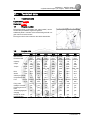 7
7
-
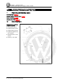 8
8
-
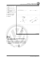 9
9
-
 10
10
-
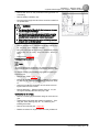 11
11
-
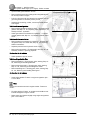 12
12
-
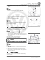 13
13
-
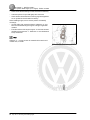 14
14
-
 15
15
-
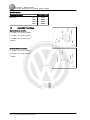 16
16
-
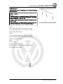 17
17
-
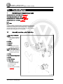 18
18
-
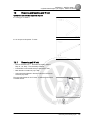 19
19
-
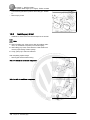 20
20
-
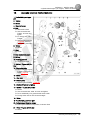 21
21
-
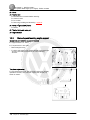 22
22
-
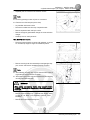 23
23
-
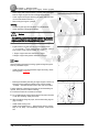 24
24
-
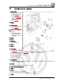 25
25
-
 26
26
-
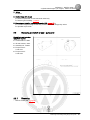 27
27
-
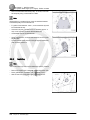 28
28
-
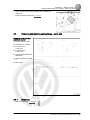 29
29
-
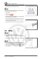 30
30
-
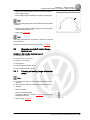 31
31
-
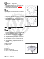 32
32
-
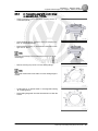 33
33
-
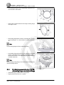 34
34
-
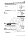 35
35
-
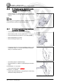 36
36
-
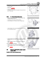 37
37
-
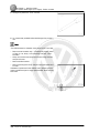 38
38
-
 39
39
-
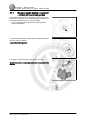 40
40
-
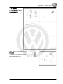 41
41
-
 42
42
-
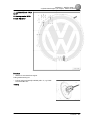 43
43
-
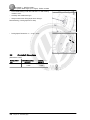 44
44
-
 45
45
-
 46
46
-
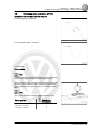 47
47
-
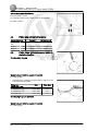 48
48
-
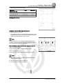 49
49
-
 50
50
-
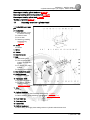 51
51
-
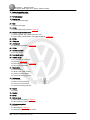 52
52
-
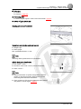 53
53
-
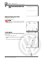 54
54
-
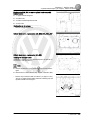 55
55
-
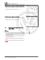 56
56
-
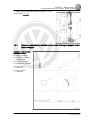 57
57
-
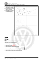 58
58
-
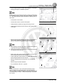 59
59
-
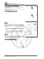 60
60
-
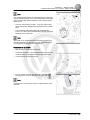 61
61
-
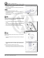 62
62
-
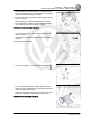 63
63
-
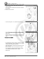 64
64
-
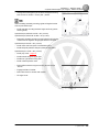 65
65
-
 66
66
-
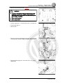 67
67
-
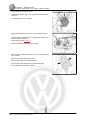 68
68
-
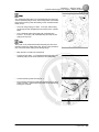 69
69
-
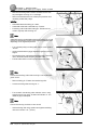 70
70
-
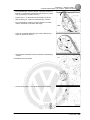 71
71
-
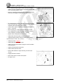 72
72
-
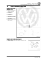 73
73
-
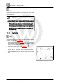 74
74
-
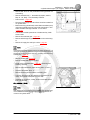 75
75
-
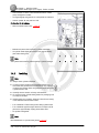 76
76
-
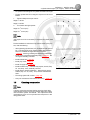 77
77
-
 78
78
-
 79
79
-
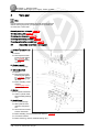 80
80
-
 81
81
-
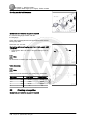 82
82
-
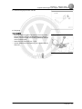 83
83
-
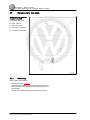 84
84
-
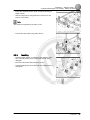 85
85
-
 86
86
-
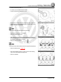 87
87
-
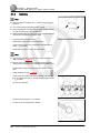 88
88
-
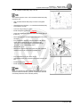 89
89
-
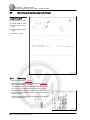 90
90
-
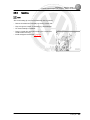 91
91
-
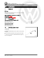 92
92
-
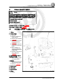 93
93
-
 94
94
-
 95
95
-
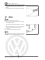 96
96
-
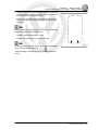 97
97
-
 98
98
-
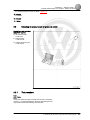 99
99
-
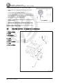 100
100
-
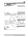 101
101
-
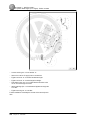 102
102
-
 103
103
-
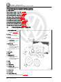 104
104
-
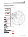 105
105
-
 106
106
-
 107
107
-
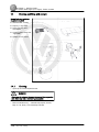 108
108
-
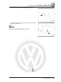 109
109
-
 110
110
-
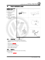 111
111
-
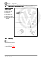 112
112
-
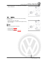 113
113
-
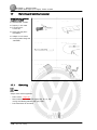 114
114
-
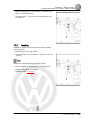 115
115
-
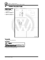 116
116
-
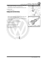 117
117
-
 118
118
-
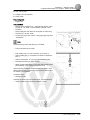 119
119
-
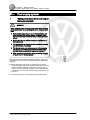 120
120
-
 121
121
-
 122
122
-
 123
123
-
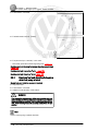 124
124
-
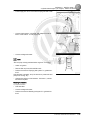 125
125
-
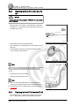 126
126
-
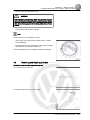 127
127
-
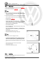 128
128
-
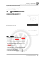 129
129
-
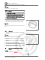 130
130
-
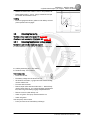 131
131
-
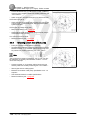 132
132
-
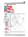 133
133
-
 134
134
-
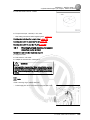 135
135
-
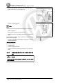 136
136
-
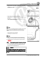 137
137
-
 138
138
-
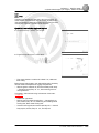 139
139
-
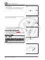 140
140
-
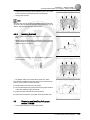 141
141
-
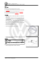 142
142
-
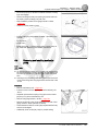 143
143
-
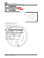 144
144
-
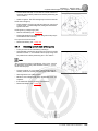 145
145
-
 146
146
-
 147
147
-
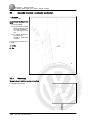 148
148
-
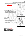 149
149
-
 150
150
-
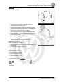 151
151
-
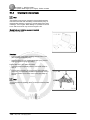 152
152
-
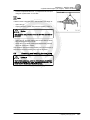 153
153
-
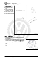 154
154
-
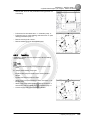 155
155
-
 156
156
-
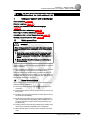 157
157
-
 158
158
-
 159
159
-
 160
160
-
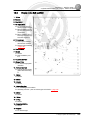 161
161
-
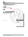 162
162
-
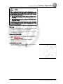 163
163
-
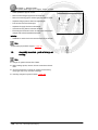 164
164
-
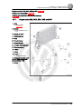 165
165
-
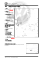 166
166
-
 167
167
-
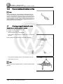 168
168
-
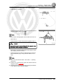 169
169
-
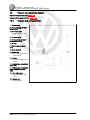 170
170
-
 171
171
-
 172
172
-
 173
173
-
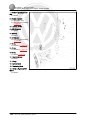 174
174
-
 175
175
-
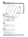 176
176
-
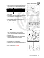 177
177
-
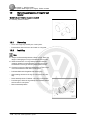 178
178
-
 179
179
-
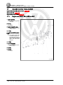 180
180
-
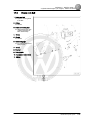 181
181
-
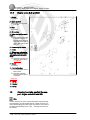 182
182
-
 183
183
-
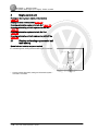 184
184
-
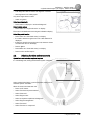 185
185
-
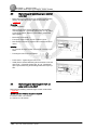 186
186
-
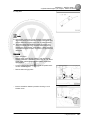 187
187
-
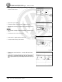 188
188
-
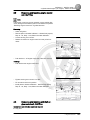 189
189
-
 190
190
-
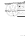 191
191
-
 192
192
-
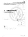 193
193
-
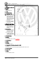 194
194
-
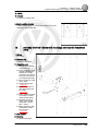 195
195
-
 196
196
-
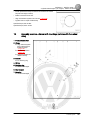 197
197
-
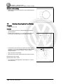 198
198
-
 199
199
-
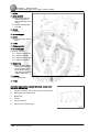 200
200
-
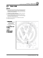 201
201
-
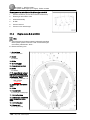 202
202
-
 203
203
-
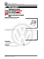 204
204
-
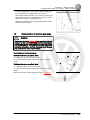 205
205
-
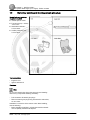 206
206
-
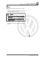 207
207


Volkswagen 2004 Golf Manual de usuario
- Categoría
- Motor
- Tipo
- Manual de usuario
- Este manual también es adecuado para
en otros idiomas
- English: Volkswagen 2004 Golf User manual
Artículos relacionados
Otros documentos
-
Nanni 4.150HE El manual del propietario
-
 Armour Line RP77363 Instrucciones de operación
-
Briggs & Stratton 58A447 Manual de usuario
-
Porsche 912E 76 Service Information
-
Land Rover L322 Range Rover Workshop Manual
-
Matco Tools MST164 Manual de usuario
-
Matco Tools MST163 Manual de usuario
-
Sea Ray 1991 LAGUNA 23 OUTBOARD El manual del propietario
-
Allmand Maxi-Lit II Manual de usuario
-
Velleman PEM10D2 Manual de usuario
