Tripp Lite DMVWSC4570XUL El manual del propietario
- Categoría
- Soportes de pared para panel plano
- Tipo
- El manual del propietario

1
1111 W. 35th Street, Chicago, IL 60609 USA • www.tripplite.com/support
Copyright © 2019 Tripp Lite. All rights reserved.
Owner’s Manual
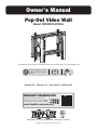
Pop-Out Video Wall
Model: DMVWSC4570XUL
200x200 / 300x200 / 300x300
400x200 / 400x300 / 400x400
600x400
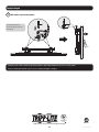
70"
MAX
154 lb.
(70 kg)
RATED
For additional instructions on installing more than one video mount, visit www.tripplite.com.
WARRANTY REGISTRATION
Register your product today and be
automatically entered to win an ISOBAR
surge protector in our monthly drawing!
www.tripplite.com/warranty
Español 16 • Français 31 • Русский 46 • Deutsch 61

2
NOTE: Read the entire instruction manual before you start assembly and installation.
Warranty and Product Registration
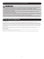
WARNING
• Do not begin the installation until you have read and understood the instructions and warnings contained in this manual.
If you have any questions regarding any of the instructions or warnings, please visit www.tripplite.com/support
• This product was designed to be installed and utilized ONLY as specified in this manual. Improper installation of this product
may cause damage or serious injury.
• This product should only be installed by someone of good mechanical ability, with basic building experience and a full
understanding of this instruction manual.
• Make sure that the unit can safely support the combined load of the equipment and all attached hardware and components.
• Always use an assistant or mechanical lifting equipment to safely lift and position equipment.
• This product is intended for indoor use only. Using this product outdoors could lead to product failure and personal injury.
5-Year Limited Warranty
Seller warrants this product, if used in accordance with all applicable instructions, to be free from original defects in material and workmanship for a period of 5 years from the date
of initial purchase. If the product should prove defective in material or workmanship within that period, Seller will repair or replace the product, in its sole discretion.
THIS WARRANTY DOES NOT APPLY TO NORMAL WEAR OR TO DAMAGE RESULTING FROM ACCIDENT, MISUSE, ABUSE OR NEGLECT. SELLER MAKES NO EXPRESS WARRANTIES
OTHER THAN THE WARRANTY EXPRESSLY SET FORTH HEREIN. EXCEPT TO THE EXTENT PROHIBITED BY APPLICABLE LAW, ALL IMPLIED WARRANTIES, INCLUDING ALL WARRANTIES
OF MERCHANTABILITY OR FITNESS, ARE LIMITED IN DURATION TO THE WARRANTY PERIOD SET FORTH ABOVE; AND THIS WARRANTY EXPRESSLY EXCLUDES ALL INCIDENTAL AND
CONSEQUENTIAL DAMAGES. (Some states do not allow limitations on how long an implied warranty lasts, and some states do not allow the exclusion or limitation of incidental or
consequential damages, so the above limitations or exclusions may not apply to you. This warranty gives you specific legal rights, and you may have other rights which vary from
jurisdiction to jurisdiction).
WARNING: The individual user should take care to determine prior to use whether this device is suitable, adequate or safe for the use intended. Since individual applications are
subject to great variation, the manufacturer makes no representation or warranty as to the suitability or fitness of these devices for any specific application.
PRODUCT REGISTRATION
Visit www.tripplite.com/warranty today to register your new Tripp Lite product. You’ll be automatically entered into a drawing for a chance to win a FREE Tripp Lite product!*
* No purchase necessary. Void where prohibited. Some restrictions apply. See website for details.
Tripp Lite has a policy of continuous improvement. Specifications are subject to change without notice. Photos and illustrations may differ slightly from actual products.

3
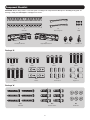
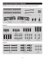
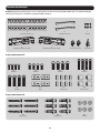
Component Checklist
IMPORTANT: Ensure that you have received all parts according to the component checklist prior to installing. If any parts are
missing or faulty, visit www.tripplite.com/support for service.
A
Wall Plate
C
M5x8
D
Left Adapter Bracket
F
Plastic Locks
G
Combo Lock
E
Right Adapter Bracket
B
Connecting Plate
Package M
Package W
M-A
M5x14
M-E
M8x30
W-A
ST6.3x55
M-B
M6x14
M-F
Washer
M-C
M8x20
M-G
Small Spacer
W-B
Concrete Anchor
M-D
M6x30
M-H
Big Spacer
W-C
D6 Washer

4
Product Dimensions
26.4 in. (670 mm)
26.4 in. (670 mm)
22.6 in. (575 mm)
20.7 in. (525 mm)
18.7 in. (475 mm)
16.7 in. (425 mm)
14.8 in. (375 mm)
12.8 in. (325 mm)
3 in.
(75 mm)
4.9 in.
(125 mm)
6.9 in. (175 mm)
8.9 in. (225 mm)
10.8 in. (275 mm)
3.74 in.
(95 mm)
Min: 7.9 in. (200 mm)
Max: 16.5 in. (418 mm)
10.9 in. (276 mm)
12 in. (304 mm)
13.5 in. (344 mm)
16.4 in. (416 mm)
16.4 in. (416 mm)
20 in. (524 mm)
2.12 in.
(54 mm)
3.74 in.
(95 mm)
Min: 7.9 in. (200 mm)
Max: 23.6 in. (600 mm)

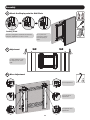
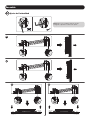
5
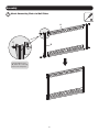
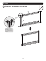
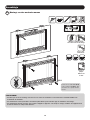
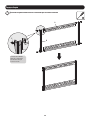
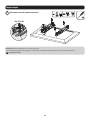
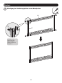
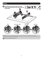
Assembly
1
Attach Connecting Plates to Wall Plates
E
A
B
Using the M5x8 screws
(E), attach the connecting
plates to the wall plates.

6
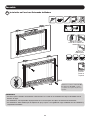
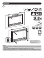
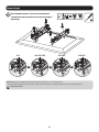
W-A
W-C
55 mm
(2.2 in.)
O/ 4.5 mm
O/ (3/16 in.)
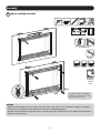
Mark the exact location of
mounting holes
Drill pilot
holes
Screw the
wall plate
onto the
wall
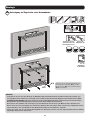
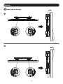
Using the ST6.3x55 screws (W-A)
and D6 washers (W-C), attach wall
plate assembly to the wall.
WARNING
• Make sure that mounting screws are anchored into the center of the studs. Use of a stud finder is highly recommended.
• Installers are responsible to provide hardware for other types of mounting situations.
• Installers must verify that the supporting surface will safely support the combined load of the equipment and all attached
hardware and components.
Assembly
2a
Mount on Wood Stud Wall

7
Assembly
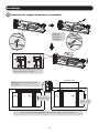
2b
Mount on Solid Brick or Concrete Block Wall
W-B
W-A
W-C
60 mm
(2.4 in.)
O/ 10 mm
O/ (3/8 in.)
Mark the exact
location of
mounting holes
Drill pilot
holes
Screw the
wall plate
onto the
wall
Using the ST6.3x55 screws (W-A), D6
washers (W-C) and concrete anchors (W-B),
attach wall plate assembly to the wall.
WARNING
• When installing wall mounts onto a concrete masonry unit (also known as a CMU or “cinder block”), verify that the actual
concrete thickness is at least 35 mm (1-3/8”) in order to hold the concrete anchors. DO NOT DRILL INTO MORTAR JOINTS!
Be sure to mount the assembled wall-mount plate with the included concrete anchors, washers and anchor bolts onto solid
sections of the blocks.
The solid sections can generally be found 25 mm (1”) toward the middle of the block from either end. An electric drill on a
slow setting is suggested to drill the hole rather than a hammer drill so as to avoid breaking out the back of the hole when
entering a hollow section.
• Installers must verify that the supporting surface will safely support the combined load of the equipment and all attached
hardware and components.

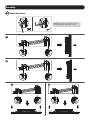
8
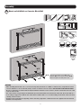
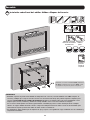
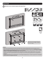
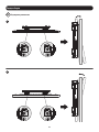
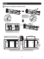
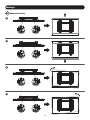
Assembly
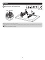
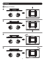
3
Install the Pop-Out Adapter Brackets
Hex Key
Ball Joint
Remove the hex
key from the
adapter brackets.
Push the pop-out arm until the ball joint snaps
into place.
D DCC
VESA 600x400
Note: Make sure the arrow is pointing up.
For VESA 600x400 mounting patterns, the “D” and “C” positions are flipped.
Top of the
display.
Top of the
display.

9
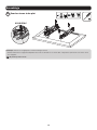
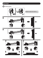
Assembly
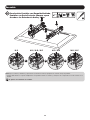
3a
For Flat Back Screens
M-F
M-A / M-B / M-C
Note: Choose appropriate screws according to the type of screen.
• Firmly secure the adapter brackets onto the display using the screws and any other necessary hardware components included with the
unit.
Do not over-tighten screws.

10
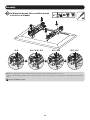
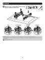
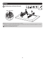
Assembly
3b
For Bump-Out Screen, Recessed Back Screen
or to Access A/V Inputs
M-C M-C / M-D / M-E M-D / M-E M-D / M-E
M-G
M-G
M-G
M-H
M-H
M-F M-F
M-F
M-F
or or or
Note: Choose appropriate screws, washers and spacers (if necessary) according to the type of screen.
• Firmly secure the adapter brackets onto the display using the screws and any other necessary hardware components included with the
unit.
Do not over-tighten screws.

11
Assembly
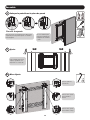
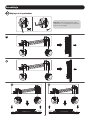
4
5
Attach the Display onto the Wall Plate
Adjustment
G
Locking Plate
Turn the locking plates downward to fasten the
wall plate. Tighten the screws to secure.
Use a padlock to
prevent the display
from tampering or
theft.
For fast alignment, push
the display to the left or
right.
5a
Micro Adjustment
For tilt adjustment.
For in/out micro
adjustment.
For up/down micro
adjustment.

12
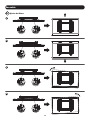
Assembly
5b
Tilt Adjustment
1
2

13
Assembly
5c
Height Adjustment
1
2
3
4

14
Assembly
5d
Depth Adjustment
1
2
3 4
Note: Only use the long end of the hex key
when tightening the adjustment screws.

15
Assembly
6
Secure and Lock the Display
Use the plastic locks (F) to
lock the display in place.
F
• Check that the bracket is secure and safe to use at regular intervals (at least every three months).
• Please visit www.tripplite.com/support if you have any questions.
1111 W. 35th Street, Chicago, IL 60609 USA • www.tripplite.com/support
19-02-230 93-3945_RevA
LVW06-46T

16
1111 W. 35th Street, Chicago, IL 60609 EE UU • En la dirección de correo electrónico www.tripplite.com/support
Copyright © 2019 Tripp Lite. Todos los derechos reservados.
Manual del Propietario
Muro de Video Emergente
Modelo: DMVWSC4570XUL
200x200 / 300x200 / 300x300 /
400x200 / 400x300 / 400x400
/ 600x400
70"
MÁXIMO
70 kg
[154 lb]
CLASIFICADO
Para más instrucciones sobre la instalación de más de un soporte para video, visite www.tripplite.com.
English 1 • Françaís 31 • Русский 46 • Deutsch 61

17
NOTA: Lea todo el manual de instrucciones antes de iniciar la instalación y ensamble.
Garantía
ADVERTENCIA
• No inicie la instalación hasta que haya leído y entendido las instrucciones y advertencias contenidas en este manual.
Si tiene cualquier pregunta con respecto a cualquiera de las instrucciones o advertencias, visite www.tripplite.com/support.
• Este producto fue diseñado para ser instalado y utilizado SOLAMENTE como se especifica en este manual. La instalación
incorrecta de este producto puede causar daños o lesiones severas.
• Este producto debe ser instalado únicamente por alguien con una buena habilidad mecánica, experiencia básica de
construcción y un entendimiento completo de este manual de instrucciones.
• Cerciórese que la unidad pueda soportar con seguridad la carga combinada de todo el hardware y componentes instalados.
• Utilice siempre un ayudante o equipo de elevación mecánico para levantar y colocar el equipo con seguridad.
• Este producto está diseñado para usarse sólo en interiores. Usar este producto en exteriores podría derivar en fallas del
producto y lesiones personales.
Garantía Limitada por 5 Años
El vendedor garantiza este producto, si se usa de acuerdo con todas las instrucciones aplicables, de que está libre de defectos en material y mano de obra por un período de 5
años a partir de la fecha de compra inicial. Si el producto resultara defectuoso en material o mano de obra dentro de ese período, el vendedor reparará o reemplazará el producto a
su entera discreción.
ESTA GARANTÍA NO SE APLICA AL DESGASTE NORMAL O A LOS DAÑOS QUE RESULTEN DE ACCIDENTES, USO INCORRECTO, USO INDEBIDO O NEGLIGENCIA. EL VENDEDOR NO
OTORGA GARANTÍAS EXPRESAS DISTINTAS A LA ESTIPULADA EN EL PRESENTE. SALVO EN LA MEDIDA EN QUE LO PROHÍBAN LAS LEYES APLICABLES, TODAS LAS GARANTÍAS
IMPLÍCITAS, INCLUYENDO TODAS LAS GARANTÍAS DE COMERCIALIZACIÓN O IDONEIDAD, ESTÁN LIMITADAS EN DURACIÓN AL PERÍODO DE GARANTÍA ESTABLECIDO; ASIMISMO,
ESTA GARANTÍA EXCLUYE EXPRESAMENTE TODOS LOS DAÑOS INCIDENTALES E INDIRECTOS. (Algunos estados no permiten limitaciones en cuanto a la duración de una garantía
y algunos estados no permiten la exclusión o limitación de daños incidentales o indirectos, de modo que las limitaciones anteriores pueden no aplicar para usted. Esta garantía le
otorga derechos legales específicos y usted puede tener otros derechos que pueden variar de una jurisdicción a otra).
ADVERTENCIA: antes de usarlo, cada usuario debe tener cuidado al determinar si este dispositivo es adecuado o seguro para el uso previsto. Ya que las aplicaciones individuales
están sujetas a gran variación, el fabricante no garantiza la adecuación de estos dispositivos para alguna aplicación específica.

18
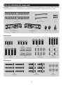
Accesorios y Partes Incluidas en el Empaque
IMPORTANTE: Asegúrese antes de instalar, de haber recibido todas las piezas de acuerdo a la lista de comprobación de
componentes. Si faltase cualquier parte o estuviese dañada, visite www.tripplite.com/support para solicitar servicio.
A
Placa de Pared
C
M5x8
D
Soporte Adaptador
Izquierdo
F
Seguros de Plástico
G
Candado de
Combinación
E
Soporte Adaptador
Derecho
B
Placa de Conexión
Paquete M
Paquete W
M-A
M5x14
M-E
M8x30
W-A
ST6.3x55
M-B
M6x14
M-F
Arandela
M-C
M8x20
M-G
Espaciador Pequeño
W-B
Taquete para Concreto
M-D
M6x30
M-H
Espaciador Grande
W-C
Arandela D6

19
Dimensiones del Producto
670 mm [26.4"]
670 mm [26.4"]
575 mm [22.6"]
525 mm [20.7"]
475 mm [18.7"]
425 mm [16.7"]
375 mm [14.8"]
325 mm [12.8"]
75 mm [3"]
125 mm 4.9"
175 mm [6.9"]
225 mm [8.9"]
275 mm [10.8"]
95 mm
[3.74"]
Mín: 200 mm [7.9"]
Máx: 418 mm [16.5"]
276 mm [10.9"]
304 mm [12"]
344 mm [13.5"]
416 mm [16.4"]
416 mm [16.4"]
524 mm [20"]
54 mm
[2.12"]
95 mm
[3.74"]
Mín: 200 mm [7.9"]
Máx: 600 mm [23.6"]

20
Ensamble
1
Fije las Placas de Conexión a las Placas de Pared
E
A
B
Utilizando los tornillos
M5x8 (E), fije las placas
de conexión a las placas
de pared.

21
W-A
W-C
55 mm
[2.2"]
O / 4.5 mm
O / (3/16")
Marque la posición
exacta de los orificios de
instalación
Barrene los
orificios piloto
Atornille la
placa de
pared en
la pared
Utilizando los tornillos ST6.3x55 (W-
A) y Arandelas D6 (W-C), coloque
el conjunto de la placa de pared en
la pared.
ADVERTENCIA
• Cerciórese que los tornillos de instalación estén anclados en el centro de los montantes. Es muy recomendable usar un
detector de vigas.
• Los instaladores son responsables de proporcionar los accesorios para otros tipos de soluciones de instalación.
• Los instaladores deben verificar que la superficie de apoyo soporte con seguridad la carga combinada de todo el hardware y
componentes instalados.
Ensamble
2a
Instalación en Pared con Entramado de Madera

22
Ensamble
2b
Instalación sobre Pared de Ladrillos Sólidos o Bloques de Concreto
W-B
W-A
W-C
60 mm
[2.4"]
O/ 10 mm
O / [3/8"]
Marque la posición
exacta de los orificios
de instalación
Barrene los
orificios
piloto
Atornille la
placa de
pared en
la pared
Utilizando los tornillos ST6.3x55 (W-A), Arandelas
D6 (W-C) y taquetes para concreto (W-B), sujete
el conjunto de la placa de pared en la pared.
ADVERTENCIA
• Al instalar soportes de pared en una unidad de mampostería de concreto (conocida también como CMU o bloques de
concreto), verifique que el espesor real del concreto sea de al menos 35 mm [1 3/8”] a fin de sujetar los taquetes para
concreto. ¡NO TALADRE EN LAS UNIONES DE ARGAMASA! Asegúrese de instalar la placa de pared ensamblada con los
taquetes para concreto, arandelas y tornillos de anclaje incluidos en las secciones sólidas de los bloques.
Las secciones sólidas pueden encontrarse generalmente a 25.4 mm [1”] hacia el centro del bloque desde cualquier
extremo. Se sugiere utilizar un taladro eléctrico a baja velocidad para barrenar el orificio en vez de un rotomartillo para
evitar rotura de la parte posterior del orificio al entrar en una sección hueca.
• Los instaladores deben verificar que la superficie de apoyo soporte con seguridad la carga combinada de todo el hardware y
componentes instalados.

23
Ensamble
3
Instale los Soportes Adaptadores Emergentes
Llave
Hexagonal
Rótula
Retire la llave
hexagonal de
los soportes
adaptadores.
Empuje el brazo emergente hasta que la rótula
se fije en su lugar.
D DCC
VESA 600x400
Nota: Asegúrese de que la flecha esté
apuntando hacia arriba.
Para patrones VESA 600x400, las posiciones “D” y “C” están volteadas.
Parte superior
de la pantalla.
Parte superior
de la pantalla.

24
Ensamble
3a
Para Pantallas con Respaldo Plano
M-F
M-A / M-B / M-C
Nota: Elija los tornillos de acuerdo al tipo de pantalla.
• Asegure firmemente los soportes adaptadores en la pantalla usando los tornillos y cualquier otro componente necesario incluido en la
unidad.
No apriete excesivamente los tornillos

25
Ensamble
3b
Para Instalar Pantallas con Respaldo Abultado,
Pantallas con Parte Posterior Cóncava o para
Acceder a las Entradas de Audio y Video
M-C M-C / M-D / M-E M-D / M-E M-D / M-E
M-G
M-G
M-G
M-H
M-H
M-F M-F
M-F
M-F
o o o
Nota: Elija los tornillos, arandelas y espaciadores (si fueran necesarios) apropiados de acuerdo al tipo de pantalla.
• Asegure firmemente los soportes adaptadores en la pantalla usando los tornillos y cualquier otro componente necesario incluido en la
unidad.
No apriete excesivamente los tornillos

26
Ensamble
4
5
Coloque la pantalla en la placa de pared
Ajuste
G
Placa de Asegurado
Gire las placas de asegurado hacia abajo para
sujetar la placa de pared. Apriete los tornillos
para asegurar.
Use un candado para
proteger la pantalla de
manipulación indebida
o robo.
Para la rápida alineación,
empuje la pantalla a la
izquierda o a la derecha.
5a
Micro Ajuste
Para el ajuste de
inclinación.
Para el micro ajuste
hacia adentro o
afuera.
Para el micro ajuste
hacia arriba o abajo.

27
Ensamble
5b
Ajuste de Inclinación
1
2

28
Ensamble
5c
Ajuste de Altura
1
2,
3
4

29
Ensamble
5d
Ajuste de Profundidad
1
2,
3 4
Nota: Utilice solo el extremo largo de la llave
hexagonal al apretar los tornillos de ajuste.

30
Ensamble
6
Asegure y Bloquee la Pantalla
Utilice los seguros de plástico
(F) para bloquear la pantalla
en su posición.
F
• Compruebe a intervalos regulares (al menos trimestralmente) que el soporte esté bien instalado y sea seguro para usarse.
• Si tiene alguna pregunta, visite por favor a www.tripplite.com/support.
1111 W. 35th Street, Chicago, IL 60609 EE. UU. • www.tripplite.com/support
19-02-230 93-3945_RevA
LVW06-46T

31
1111 W. 35th Street, Chicago, IL 60609 USA • www.tripplite.com/support
Droits d'auteur © 2019 Tripp Lite. Tous droits réservés.
Manuel de l'utilisateur
Mur vidéo escamotable
Modèle : DMVWSC4570XUL
200 x 200/300 x 200/300 x 300
400 x 200/400 x 300/400 x 400
600 x 400
177,8 cm
(70 po)
MAX.
70 kg
(154 lb)
CAPACITÉ
NOMINALE
Pour des instructions supplémentaires sur l'installation de plus d'un support vidéo, visiter www.tripplite.com.
English 1 • Español 16 • Русский 46 • Deutsch 61

32
REMARQUE : Lire le manuel d'instructions en entier avant de commencer l'assemblage et l'installation.
Garantie
AVERTISSEMENT
• Ne pas commencer l'installation avant d'avoir lu et compris les instructions et les avertissements contenus dans le présent
manuel. Pour toute question concernant les instructions ou les avertissements, veuillez visiter www.tripplite.com/support.
• Ce produit a été conçu pour être installé et utilisé UNIQUEMENT comme spécifié dans le présent manuel. Une mauvaise
installation risque de causer des dommages ou des blessures graves.
• Ce produit ne devrait être installé que par une personne ayant de bonnes aptitudes en mécanique et une expérience de
base en construction de même qu'une pleine connaissance du présent manuel d'instructions.
• S'assurer que le produit peut supporter sans risque la charge combinée de l'équipement et de tout le matériel et
composants attachés.
• Toujours faire appel à un assistant ou utiliser de l'équipement de levage mécanique pour soulever et mettre en place
l'équipement.
• Ce produit est prévu pour être utilisé à l'intérieur uniquement. L'utilisation de ce produit à l'extérieur pourrait entraîner une
défaillance du produit et des lésions corporelles.
Garantie limitée de 5 ans
Le vendeur garantit ce produit, s'il est utilisé conformément à toutes les instructions applicables, est exempt de tous défauts de matériaux et de fabrication pour une période de 5
ans à partir de la date d'achat initiale. Si le produit s'avère défectueux en raison d'un vice de matériaux ou de fabrication au cours de cette période, le vendeur s'engage à réparer ou
remplacer le produit, à sa seule discrétion.
CETTE GARANTIE NE S'APPLIQUE PAS À L'USURE NORMALE OU AUX DOMMAGES RÉSULTANT D'UNE MAUVAISE UTILISATION, D'UN ABUS OU D'UNE NÉGLIGENCE. LE VENDEUR
N'ACCORDE AUCUNE GARANTIE EXPRESSE AUTRE QUE LA GARANTIE EXPRESSÉMENT DÉCRITE DANS LE PRÉSENT DOCUMENT. SAUF DANS LA MESURE OÙ CELA EST INTERDIT
PAR LA LOI EN VIGUEUR, TOUTE GARANTIE IMPLICITE, Y COMPRIS TOUTES LES GARANTIES DE QUALITÉ MARCHANDE OU D'ADAPTATION, SONT LIMITÉES À LA PÉRIODE DE
GARANTIE CI-DESSUS ET CETTE GARANTIE EXCLUT EXPRESSÉMENT TOUS DOMMAGES DIRECTS ET INDIRECTS. (Certains États ne permettent pas de limitations sur la durée d'une
garantie implicite, et certains États ne permettent pas l'exclusion ou la limitation des dommages fortuits ou consécutifs, de sorte que les limitations ou exclusions susmentionnées
peuvent ne pas s'appliquer à vous. Cette garantie vous accorde des droits légaux spécifiques, et vous pouvez avoir d'autres droits qui varient d'une compétence à l'autre).
AVERTISSEMENT : L'utilisateur individuel doit prendre soin de déterminer avant l'utilisation si cet appareil est approprié, adéquat et sûr pour l'usage prévu. Puisque les utilisations
individuelles sont sujettes à des variations importantes, le fabricant ne fait aucune déclaration ou garantie quant à l'aptitude ou l'adaptation de ces dispositifs pour une application
spécifique.

33
Liste de vérification des composants
IMPORTANT : S'assurer d'avoir reçu toutes les pièces conformément à la liste de vérification des composants avant de procéder
à l'installation. Si des pièces sont manquantes ou défectueuses, visiter www.tripplite.com/support pour obtenir de l'aide.
A
plaque murale
C
M5 x 8
D
support d'adaptateur
gauche
F
verrous en plastique
G
verrou combo
E
support d'adaptateur
droit
B
plaque de connexion
Emballage M
Emballage W
M-A
M5 x 14
M-E
M8 x 30
W-A
ST6.3x55
M-B
M6 x 14
M-F
rondelle
M-C
M8 x 20
M-G
petite entretoise
W-B
ancrage à béton
M-D
M6 x 30
M-H
grande entretoise
W-C
rondelle D6

34
Dimensions du produit
670 mm (26,4 po)
670 mm (26,4 po)
575 mm (22,6 po)
525 mm (20,7 po)
475 mm (18,7 po)
425 mm (16,7 po)
375 mm (14,8 po)
325 mm (12,8 po)
75 mm
(3 po)
125 mm
(4,9 po)
175 mm (6,9 po)
225 mm (8,9 po)
275 mm (10,8 po)
95 mm
(3,74 po)
Min. : 200 mm (7,9 po)
Max. : 418 mm (16,5 po)
276 mm (10,9 po)
304 mm (12 po)
344 mm (13,5 po)
416 mm (16,4 po)
416 mm (16,4 po)
524 mm (20 po)
54 mm
(2,12 po)
95 mm
(3,74 po)
Min. : 200 mm (7,9 po)
Max. : 600 mm (23,6 po)

35
Assemblage
1
Fixation des plaques de connexion aux plaques murales
E
A
B
À l'aide des vis M5x8
(E), fixer les plaques de
connexion aux plaques
murales.

36
W-A
W-C
55 mm
(2,2 po)
O/ 4,5 mm
O/ (3/16 po)
Marquer l’emplacement
exact des trous de montage.
Percer des
avant-trous.
Visser la
plaque
murale sur
le mur.
À l'aide des vis ST6.3x55 (W-A)
et des rondelles D6 (W-C), fixer
l'ensemble de la plaque murale
au mur.
AVERTISSEMENT
• S'assurer que les vis de montage sont ancrées au centre des montants. Il est fortement recommandé d'utiliser un
localisateur de montants.
• Les installateurs sont responsables de fournir la quincaillerie pour tout autre type de situations de montage.
• Les installateurs doivent s'assurer que la surface d'appui va supporter sans risque la charge combinée de l'équipement et
de tout le matériel et composants attachés.
Assemblage
2a
Montage sur des montants muraux

37
Assemblage
2b
Montage sur de la brique solide ou un mur en blocs de béton
W-B
W-A
W-C
60 mm
(2,4 po)
O/ 10 mm
O/ (3/8 po)
Marquer
l’emplacement exact
des trous de montage.
Percer des
avant-trous.
Visser la
plaque
murale sur
le mur.
À l'aide des vis ST6.3x55 (W-A), des
rondelles D6 (W-C) et des ancrages à béton
(W-B), fixer l'ensemble de la plaque murale
au mur.
AVERTISSEMENT
• Lorsque les montages muraux sont installés sur un élément de maçonnerie en béton (également appelé bloc de béton ou
« bloc de béton de mâchefer »), vérifier que l'épaisseur réelle du béton est d'au moins 35 mm (1-3/8 po) afin que le béton
puisse supporter les ancrages à béton. NE PAS PERCER DANS LES JOINTS DE MORTIER! S'assurer de monter la plaque
murale assemblée avec les ancrages à béton, les rondelles et les boulons d'ancrage inclus dans les sections solides des
blocs.
Les sections solides se trouvent habituellement à 25 mm (1 po) vers le milieu du bloc à partir de chaque extrémité. Il est
suggéré d'utiliser une perceuse électrique pour percer un trou plutôt qu'un marteau perforateur afin d'éviter d'endommager
l'arrière du trou en présence d'un espace vide.
• Les installateurs doivent s'assurer que la surface d'appui va supporter sans risque la charge combinée de l'équipement et
de tout le matériel et composants attachés.

38
Assemblage
3
Installation des supports d'adaptateur escamotables
Clé
hexagonale
Joint à rotule
Retirer la clé
hexagonale
des supports
d'adaptateur.
Pousser le bras escamotable jusqu'à ce que le
joint à rotule s'enclenche en place.
D DCC
VESA 600 x 400
Remarque :S'assurer que la flèche pointe
vers le haut.
Pour les motifs de montage VESA 600 x 400, les positions « D » et « C » sont inversées.
Haut de l'écran
Haut de l'écran

39
Assemblage
3a
Pour les écrans à dos plat
M-F
M-A/M-B/M-C
Remarque : Choisir les vis appropriées en fonction du type d'écran.
• Retenir fermement les supports d'adaptateur sur l'écran en utilisant les vis et tout autre composant de quincaillerie nécessaire inclut
avec l'appareil.
Ne pas trop serrer les vis.

40
Assemblage
3b
Pour les écrans escamotables, à dos encastré
ou pour accéder aux entrées AV
M-C M-C/M-D/M-E M-D/M-E M-D/M-E
M-G
M-G
M-G
M-H
M-H
M-F M-F
M-F
M-F
ou ou ou
Remarque : Choisir les vis, les rondelles et les entretoises appropriées (le cas échéant) en fonction du type d'écran.
• Retenir fermement les supports d'adaptateur sur l'écran en utilisant les vis et tout autre composant de quincaillerie nécessaire inclut
avec l'appareil.
Ne pas trop serrer les vis.

41
Assemblage
4
5
Fixation de l'écran à la plaque murale
Réglage
G
Plaque de verrouillage
Tourner les plaques de verrouillage pour fixer
la plaque murale. Serrer les vis pour retenir en
place.
Utiliser un cadenas
pour protéger l'écran
contre l'altération et
le vol.
Pour un alignement rapide,
pousser vers la gauche ou
vers la droite.
5a
Micro-ajustement
Pour le réglage de
l'inclinaison.
Pour le micro-
ajustement vers
l'intérieur/extérieur.
Pour le micro-
ajustement vers le
haut/bas.

42
Assemblage
5b
Réglage de l'inclinaison
1
2

43
Assemblage
5c
Réglage de la hauteur
1
2
3
4

44
Assemblage
5d
Réglage de la profondeur
1
2
3 4
Remarque : Utiliser uniquement la longue
extrémité de la clé hexagonale au moment de
serrer les vis de réglage.

45
Assemblage
6
Fixation et verrouillage de l'écran
Utiliser les verrous en
plastique (F) pour verrouiller
l'écran en place.
F
• Vérifier à intervalles réguliers que le support peut être utilisé de façon sûre et sécuritaire (au moins tous les trois mois).
• Pour toute question, visiter www.tripplite.com/support.
1111 W. 35th Street, Chicago, IL 60609 USA • www.tripplite.com/support
19-02-230 93-3945_RevA
LVW06-46T

46
1111 W. 35th Street, Chicago, IL 60609 USA • www.tripplite.com/support
Охраняется авторским правом © 2019 Tripp Lite. Перепечатка запрещается.
Руководство пользователя
Выдвижная видеостена
Модель: DMVWSC4570XUL
200x200 / 300x200 / 300x300 400x200 /
400x300 / 400x400
600x400
70"
МАКС.
70 кг
МАКС.
Дополнительные указания по установке более чем одного кронштейна см. на странице www.tripplite.com.
English 1 • Español 16 • Français 31 • Deutsch 61

47
ПРИМЕЧАНИЕ. Перед началом установки и сборки модуля внимательно изучите все разделы руководства.
Гарантийные обязательства
ВНИМАНИЕ!
• Не начинайте установку до тех пор, пока не ознакомитесь со всеми указаниями и предупреждениями, изложенными в настоящем руководстве, и не поймете их
смысл. При возникновении любых вопросов относительно любых указаний или предупреждений посетите страницу www.tripplite.com/support.
• Данное изделие предназначено для установки и использования ТОЛЬКО в целях, указанных в настоящем руководстве. Неправильная установка данного изделия
может привести к причинению материального ущерба или существенного вреда здоровью людей.
• Установка данного изделия должна производиться только специалистом с достаточной технической квалификацией и базовыми навыками строительства, в
полной мере понимающим смысл информации, изложенной в настоящем руководстве.
• Убедитесь в том, что данное изделие может с запасом выдерживать суммарную нагрузку, создаваемую оборудованием и всеми входящими в комплект
деталями оснастки и другими компонентами.
• Для безопасного подъема и надлежащего размещения оборудования обязательно обращайтесь за помощью или пользуйтесь грузоподъемным оборудованием.
• Данное изделие предназначено для использования только в закрытых помещениях. Использование данного изделия на открытом воздухе может привести к его
выходу из строя и причинению вреда здоровью людей.
Условия 5-летней ограниченной гарантии
Продавец гарантирует отсутствие изначальных дефектов материала или изготовления в течение 5 лет с момента первоначальной покупки данного изделия при условии его использования в соответствии со всеми применимыми к нему
указаниями. В случае проявления каких-либо дефектов материала или изготовления в течение указанного периода Продавец осуществляет ремонт или замену данного изделия исключительно по своему усмотрению.
ДЕЙСТВИЕ НАСТОЯЩЕЙ ГАРАНТИИ НЕ РАСПРОСТРАНЯЕТСЯ НА СЛУЧАИ ЕСТЕСТВЕННОГО ИЗНОСА ИЛИ ПОВРЕЖДЕНИЯ В РЕЗУЛЬТАТЕ АВАРИИ, НЕНАДЛЕЖАЩЕГО ИСПОЛЬЗОВАНИЯ, НАРУШЕНИЯ ПРАВИЛ ЭКСПЛУАТАЦИИ ИЛИ ХАЛАТНОСТИ. ПРОДАВЕЦ
НЕ ПРЕДОСТАВЛЯЕТ НИКАКИХ ЯВНО ВЫРАЖЕННЫХ ГАРАНТИЙ ЗА ИСКЛЮЧЕНИЕМ ПРЯМО ИЗЛОЖЕННОЙ В НАСТОЯЩЕМ ДОКУМЕНТЕ. ЗА ИСКЛЮЧЕНИЕМ СЛУЧАЕВ, ЗАПРЕЩЕННЫХ ДЕЙСТВУЮЩИМ ЗАКОНОДАТЕЛЬСТВОМ, ВСЕ ПОДРАЗУМЕВАЕМЫЕ
ГАРАНТИИ, ВКЛЮЧАЯ ВСЕ ГАРАНТИИ ПРИГОДНОСТИ ДЛЯ ПРОДАЖИ ИЛИ ИСПОЛЬЗОВАНИЯ ПО НАЗНАЧЕНИЮ, ОГРАНИЧЕНЫ ПО ПРОДОЛЖИТЕЛЬНОСТИ ДЕЙСТВИЯ ВЫШЕУКАЗАННЫМ ГАРАНТИЙНЫМ СРОКОМ; КРОМЕ ТОГО, ИЗ НАСТОЯЩЕЙ
ГАРАНТИИ ЯВНЫМ ОБРАЗОМ ИСКЛЮЧАЮТСЯ ВСЕ ПОБОЧНЫЕ, СЛУЧАЙНЫЕ И КОСВЕННЫЕ УБЫТКИ. (В некоторых штатах не допускается введение ограничений на продолжительность действия тех или иных подразумеваемых гарантий,
а в некоторых - исключение или ограничение размера побочных или косвенных убытков. В этих случаях вышеизложенные ограничения или исключения могут на вас не распространяться. Настоящая гарантия предоставляет вам
конкретные юридические права, а набор других ваших прав может быть различным в зависимости от юрисдикции).
ВНИМАНИЕ! До начала использования данного устройства пользователь должен убедиться в том, что оно является пригодным, соответствующим или безопасным для предполагаемого применения. В связи с большим разнообразием
конкретных применений производитель не дает каких-либо заверений или гарантий относительно пригодности данных изделий для какого-либо конкретного применения или их соответствия каким-либо конкретным требованиям.

48
Перечень комплектации
ВНИМАНИЕ! Перед началом установки убедитесь в том, что вами получены все детали согласно перечню комплектации. В случае отсутствия или повреждения
каких-либо деталей обратитесь за помощью на страницу www.tripplite.com/support.
A
Пластина для крепления к стене
C
Винт M5x8
D
Переходный кронштейн левосторонний
F
Пластмассовые фиксаторы
G
Кодовый замок
E
Переходный кронштейн правосторонний
B
Соединительная пластина
Упаковочный комплект M
Упаковочный комплект W
M-A
Винт M5x14
M-E
Винт M8x30
W-A
Саморез ST6.3x55
M-B
Винт M6x14
M-F
Шайба
M-C
Винт M8x20
M-G
Малая проставка
W-B
Анкер для бетона
M-D
Винт M6x30
M-H
Большая проставка
W-C
Шайба D6

49
Размеры изделия
670 мм
670 мм
575 мм
525 мм
475 мм
425 мм
375 мм
325 мм
75 мм
125 мм
175 мм
225 мм
275 мм
95 мм
Мин. 200 мм
Макс. 418 мм
276 мм
304 мм
344 мм
416 мм
416 мм
524 мм
54 мм
95 мм
Мин. 200 мм
Макс. 600 мм

50
Порядок сборки
1
Крепление соединительных пластин к пластинам для настенного монтажа
E
A
B
С помощью винтов M5x8 (E)
прикрепите соединительные
пластины к пластинам для
настенного монтажа.

51
W-A
W-C
55 мм
O/4,5 мм
Разметьте точное местоположение
монтажных отверстий
Высверлите
направляющие отверстия
Привинтите
крепежную
пластину к
стене
Прикрепите скрепленные между собой
пластины к стене при помощи саморезов
ST6.3x55 (W-A) и шайб D6 (W-C).
ВНИМАНИЕ!
• Необходимо обеспечить ввертывание крепежных винтов по центру элементов каркаса. С этой целью настоятельно рекомендуется использование детектора
неоднородностей.
• Ответственность за обеспечение подходящей крепежной оснастки для других способов монтажа возлагается на установщика.
• Установщик обязан убедиться в том, что опорная поверхность с запасом выдержит суммарную нагрузку, создаваемую оборудованием и всеми входящими в
комплект деталями оснастки и другими компонентами.
Порядок сборки
2a
Крепление к стене с деревянным каркасом

52
Порядок сборки
2b
Крепление к стене из сплошного кирпича или бетонных блоков
W-B
W-A
W-C
60 мм
O/ 10 мм
Разметьте точное
местоположение
монтажных отверстий
Высверлите
направляющие
отверстия
Привинтите
крепежную
пластину к
стене
Прикрепите скрепленные между собой пластины к стене
при помощи саморезов ST6.3x55 (W-A), шайб D6 (W-C) и
анкеров для бетона (W-B).
ВНИМАНИЕ!
• При монтаже настенных кронштейнов на бетонный строительный блок (известный также как БСБ или “шлакобетонный блок”) убедитесь в том, что
фактическая толщина бетона составляет не менее 35 мм с целью обеспечения надлежащей фиксации анкеров для бетона. НЕ ВЫСВЕРЛИВАЙТЕ ОТВЕРСТИЯ В
ШВАХ, ЗАПОЛНЕННЫХ СТРОИТЕЛЬНЫМ РАСТВОРОМ! Пластину для настенного крепления в сборе обязательно следует монтировать с помощью поставляемых
в комплекте с ней анкеров для бетона, шайб и анкерных болтов в сплошных частях блоков.
Сплошные части обычно находятся на расстоянии 25 мм от любого из краев блока к его центру. Во избежание разрушения задней стенки отверстия при
попадании сверла в полую часть, для высверливания отверстия рекомендуется использовать электрическую дрель на малой скорости вращения вместо
перфоратора.
• Установщик обязан убедиться в том, что опорная поверхность с запасом выдержит суммарную нагрузку, создаваемую оборудованием и всеми входящими в
комплект деталями оснастки и другими компонентами.

53
Порядок сборки
3
Установка выдвижных переходных кронштейнов
Шестигранный
ключ
Шаровое соединение
Выньте шестигранный
ключ из переходных
кронштейнов.
Надавите на выдвижной рычаг до защелкивания шарового
соединения.
D DCC
VESA 600x400
Примечание. Убедитесь в том, что стрелка направлена вверх.
Для монтажных шаблонов VESA 600x400 позиции "D" и "C" меняются на противоположные.
Верх дисплея.
Верх дисплея.

54
Порядок сборки
3a
Для экранов с плоской задней поверхностью
M-F
M-A / M-B / M-C
Примечание. Выбирайте подходящие винты в соответствии с типом экрана.
• Прочно прикрепите переходные кронштейны к дисплею с помощью винтов и любых других необходимых крепежных элементов, поставляемых в комплекте.
Не перетягивайте винты.

55
Порядок сборки
3b
Для выдвижных экранов / экранов, устанавливаемых
заподлицо или для получения доступа к разъемам аудио-/
видеовхода
M-C M-C / M-D / M-E M-D / M-E M-D / M-E
M-G
M-G
M-G
M-H
M-H
M-F M-F
M-F
M-F
или или или
Примечание. Выбирайте подходящие винты, шайбы и распорки (при необходимости) в соответствии с типом экрана.
• Прочно прикрепите переходные кронштейны к дисплею с помощью винтов и любых других необходимых крепежных элементов, поставляемых в комплекте.
Не перетягивайте винты.

56
Порядок сборки
4
5
Прикрепите дисплей к пластине для настенного монтажа
Корректировка
положения
G
Запирающая пластина
Поверните запирающие пластины вниз для фиксации
пластины настенного крепления. Затяните винты до упора.
Для предотвращения
вскрытия или кражи дисплея
используйте навесной замок.
Для быстрого выравнивания
дисплея сдвиньте его влево или
вправо.
5a
Микрорегулировка
Для регулировки угла
наклона.
Для микрометрической
регулировки выдвижения.
Для микрометрической
регулировки по высоте.

57
Порядок сборки
5b
Регулировка угла наклона
1
2

58
Порядок сборки
5c
Регулировка высоты
1
2
3
4

59
Порядок сборки
5d
Регулировка глубины
1
2
3 4
Примечание. При затяжке регулировочных винтов
используйте только длинный конец шестигранного ключа.

60
Порядок сборки
6
Фиксация и закрепление дисплея
Для закрепления дисплея на
месте используйте пластмассовые
фиксаторы (F).
F
• Регулярно (не реже, чем раз в три месяца) проверяйте надежность крепления кронштейна и безопасность его использования.
• В случае возникновения каких-либо вопросов посетите страницу www.tripplite.com/support.
1111 W. 35th Street, Chicago, IL 60609 USA • www.tripplite.com/support
19-02-230 93-3945_RevA
LVW06-46T

61
1111 W. 35th Street, Chicago, IL 60609 USA • www.tripplite.com/support
Copyright © 2019 Tripp Lite. Alle Rechte vorbehalten.
Benutzerhandbuch
Ausklappbare Videowand
Modell: DMVWSC4570XUL
200x200 / 300x200 / 300x300
400x200 / 400x300 / 400x400
600x400
70"
max.
70 kg
(154 lb.)
GESCHÄTZT
Weitere Anweisungen zum Installieren mehrerer Videohalterungen finden Sie auf www.tripplite.com.
English 1 • Español 16 • Français 31 • Русский 46

62
HINWEIS: Lesen Sie das gesamte Handbuch, bevor Sie mit der Installation und Montage beginnen.
Garantie
WARNUNG
• Beginnen Sie nicht mit dem Einbau, bevor Sie die Anweisungen und Warnhinweise in diesem Handbuch gelesen und
verstanden haben. Sollten Sie Fragen bezüglich der Anweisungen oder Warnhinweise haben, besuchen Sie bitte www.
tripplite.com/support.
• Dieses Produkt wurde so entwickelt, dass es NUR wie in dieser Bedienungsanleitung angegeben installiert und verwendet
werden darf. Die unsachgemäße Installation dieses Produkts kann zu Schäden und schweren Verletzungen führen.
• Dieses Produkt darf nur von einer Person mit guten Montagefähigkeiten und Grunderfahrung im Bauwesen montiert werden,
die alle Anweisungen in der vorliegenden Montageanleitung vollständig verstanden hat.
• Stellen Sie sicher, dass die Einheit das Gewicht des Geräts sowie das zugehörige Material und sämtliche zugehörigen
Komponenten tragen kann.
• Verwenden Sie eine mechanische Hebevorrichtung, um das Gerät sicher anzuheben und zu positionieren.
• Dieses Produkt ist nur für den Einsatz in geschlossenen Räumen geeignet. Die Verwendung dieses Produktes im Freien kann
zu Fehlfunktionen und Verletzungen führen.
5-Jahres-Garantie
Der Verkäufer garantiert für einen Zeitraum von fünf Jahren ab Kaufdatum, dass das Produkt weder Material- noch Herstellungsfehler aufweist, wenn es gemäß aller zutreffenden
Anweisungen verwendet wird. Wenn das Produkt in diesem Zeitraum Material- oder Herstellungsfehler aufweist, kann der Verkäufer diese Fehler nach eigenem Ermessen beheben
oder das Produkt ersetzen.
DIE NORMALE ABNUTZUNG ODER BESCHÄDIGUNGEN AUFGRUND VON UNFÄLLEN, MISSBRAUCH ODER UNTERLASSUNG WERDEN VON DIESER GARANTIE NICHT GEDECKT.
AUSSER DEN NACHSTEHEND AUSDRÜCKLICH DARGELEGTEN GARANTIEBEDINGUNGEN ÜBERNIMMT DER VERKÄUFER KEINERLEI GARANTIE. AUSSER WENN VON DEN
GÜLTIGEN GESETZEN UNTERSAGT, SIND ALLE IMPLIZIERTEN GARANTIEN, EINSCHLIESSLICH ALLE GARANTIEN FÜR DIE GEBRAUCHSTAUGLICHKEIT ODER EIGNUNG AUF DIE
OBEN FESTGELEGTE GARANTIEDAUER BESCHRÄNKT. DIESE GARANTIE SCHLIESST AUSDRÜCKLICH ALLE FOLGESCHÄDEN UND BEILÄUFIG ENTSTANDENEN SCHÄDEN AUS. (Da
einige Länder den Ausschluss oder die Beschränkung von Folgeschäden oder beiläufig entstandenen Schäden sowie den Ausschluss von implizierten Garantien oder die zeitliche
Beschränkung einer implizierten Garantie untersagen, sind die oben genannten Beschränkungen für Sie möglicherweise nicht zutreffend. Diese Garantie gibt Ihnen bestimmte
Rechte. Sie haben jedoch möglicherweise andere Rechte, die abhängig von der Gerichtsbarkeit variieren können.)
WARNUNG: Der Benutzer muss vor der Verwendung überprüfen, ob das Gerät für den beabsichtigten Zweck geeignet und angemessen ist und ob der Einsatz sicher ist. Da die
Anwendungen variieren können, übernimmt der Hersteller keine Garantie bezüglich der Eignung dieser Geräte für einen bestimmten Verwendungszweck.

63
Komponentenliste
WICHTIG: Überprüfen Sie, ob Sie alle in der Komponentenliste aufgeführten Teile erhalten haben, bevor Sie mit der Installation
beginnen. Wenn Teile beschädigt oder nicht vorhanden sind, besuchen Sie bitte www.tripplite.com/support.
A
Wandplatte
C
M5x8
D
Linke Adapterhalterung
F
Kunststoffverriegelungen
G
Kombischloss
E
Rechte Adapterhalterung
B
Verbindungsplatte
Paket M
Paket W
M-A
M5x14
M-E
M8x30
W-A
ST6.3x55
M-B
M6x14
M-F
Beilagscheibe
M-C
M8x20
M-G
Kleiner Abstandhalter
W-B
Betonanker
M-D
M6x30
M-H
Großer Abstandhalter
W-C
D6 Beilagscheibe

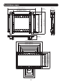
64
Produktabmessungen
670 mm (26,4 Zoll)
670 mm (26,4 Zoll)
575 mm (22,6 Zoll)
525 mm (20,7 Zoll)
475 mm (18,7 Zoll)
425 mm (16,7 Zoll)
375 mm (14,8 Zoll)
325 mm (12,8 Zoll)
75 mm
(3 Zoll)
125 mm
(4,9 Zoll)
175 mm (6,9 Zoll)
225 mm (8,9 Zoll)
275 mm (10,8 Zoll)
95 mm
(3,74 Zoll)
Min: 200 mm (7,9 Zoll)
Max: 418 mm (16,5 Zoll)
276 mm (10,9 Zoll)
304 mm (12 Zoll)
344 mm (13,5 Zoll)
416 mm (16,4 Zoll)
416 mm (16,4 Zoll)
524 mm (20 Zoll)
54 mm
(2,12 Zoll)
95 mm
(3,74 Zoll)
Min: 200 mm (7,9 Zoll)
Max: 600 mm (23,6 Zoll)

65
Montage
1
Befestigung der Verbindungsplatten an den Wandplatten
E
A
B
Befestigen Sie die
Verbindungsplatten
mithilfe der M5x8-
Schrauben (E) an den
Wandplatten.

66
W-A
W-C
55 mm
(2,2 Zoll)
O/ 4,5 mm
O/ (3/16 Zoll)
Markieren Sie die genaue
Position der Befestigungslöcher
Bohren Sie
Führungslöcher
Schrauben
Sie die
Wandplatte
an die Wand
Befestigen Sie die Wandmontageplatte
mit den Schrauben ST6.3x55 (W-A)
und die D6-Beilagscheiben (W-C) an
der Wand.
WARNUNG
• Stellen Sie sicher, dass die Befestigungsschrauben in der Mitte der Balken verankert sind. Wir empfehlen die Verwendung
eines Balkensuchers.
• Für andere Befestigungsarten muss das Material vom Monteur bereitgestellt werden.
• Stellen Sie sicher, dass die verwendete Montagefläche das Gewicht des Geräts sowie das zugehörige Material und sämtliche
zugehörigen Komponenten tragen kann.
Montage
2a
Befestigen am Holzwandbalken

67
Montage
2b
Befestigung an Ziegelstein- oder Betonwänden
W-B
W-A
W-C
60 mm
(2,4 Zoll)
O/ 10 mm
O/ (3/8 Zoll)
Markieren Sie die
genaue Position der
Befestigungslöcher
Bohren Sie
Führungslöcher
Schrauben
Sie die
Wandplatte
an die Wand
Befestigen Sie die Wandmontageplatte mit
den Schrauben ST6.3x55 (W-A), den D6-
Beilagscheiben (W-C) und den Betonankern
(W-B) an der Wand.
WARNUNG
• Vergewissern Sie sich bei einer Montage der Wandhalterung an Betonmauerwerk (auch Betonschalstein genannt), dass
der eigentliche Beton mindestens eine Stärke von 1-3/8 Zoll (35 mm) für die Befestigung des Betonankers bietet. NICHT
IN MÖRTELFUGEN BOHREN! Achten Sie darauf, die montierte Wandhalterungsplatte mit den beiliegenden Verankerungen,
Beilagscheiben und Verankerungsbolzen an den massiven Teilen der Blöcke zu montieren.
Die massiven Teile befinden sich in der Regel von jedem Blockende aus 25 mm (1”) zur Mitte hin. Wir empfehlen beim
Bohren des Loches die Verwendung einer elektrischen Bohrmaschine auf geringer Stufe, anstatt einer Schlagbohrmaschine,
um zu vermeiden, dass beim Eintritt in einen Hohlraum die Rückseite des Bohrloches einbricht.
• Stellen Sie sicher, dass die verwendete Montagefläche das Gewicht des Geräts sowie das zugehörige Material und sämtliche
zugehörigen Komponenten tragen kann.

68
Montage
3
Montage der ausklappbaren Adapterhalterungen
Inbusschlüssel
Kugelgelenk
Entfernen Sie den
Inbusschlüssel von den
Adapterhalterungen.
Schieben Sie den Ausstellarm nach außen, bis
das Kugelgelenk einrastet.
D DCC
VESA 600x400
Hinweis: Stellen Sie sicher, dass der Pfeil nach
oben zeigt.
Bei VESA 600x400-Montagemustern sind die Positionen „D“ und „C“ umgekehrt.
Oberseite des
Bildschirms.
Oberseite des
Bildschirms.

69
Montage
3a
Für Bildschirme mit flacher Rückseite
M-F
M-A / M-B / M-C
Hinweis: Verwenden Sie für diesen Bildschirmtyp geeignete Schrauben.
• Schrauben Sie die Adapterhalterungen unter Verwendung der Schrauben und aller anderen notwendigen Befestigungsteile, die mit der
Einheit mitgeliefert werden, sicher am Bildschirm fest.
Ziehen Sie die Schrauben nicht zu fest an.

70
Montage
3b
Für Bildschirme mit nach außen stehender
oder vertiefter Rückseite oder den Zugriff auf
A/V-Eingänge
M-C M-C / M-D / M-E M-D / M-E M-D / M-E
M-G
M-G
M-G
M-H
M-H
M-F M-F
M-F
M-F
oder oder oder
Hinweis: Verwenden Sie für diesen Bildschirmtyp geeignete Schrauben, Beilagscheiben und Abstandhalter (falls erforderlich).
• Schrauben Sie die Adapterhalterungen unter Verwendung der Schrauben und aller anderen notwendigen Befestigungsteile, die mit der
Einheit mitgeliefert werden, sicher am Bildschirm fest.
Ziehen Sie die Schrauben nicht zu fest an.

71
Montage
4
5
Den Bildschirm in die Wandplatte einhängen
Einstellung
G
Verriegelungsplatte
Drehen Sie die Sicherungsplatten nach unten,
um die Wandplatte zu befestigen. Ziehen Sie
die Schrauben fest.
Verwenden Sie ein
Vorhängeschloss, um
zu verhindern, dass der
Bildschirm manipuliert
oder gestohlen wird.
Zum schnellen Ausrichten
drücken Sie den
Bildschirm nach links oder
rechts.
5a
Mikro-Einstellung
Zur Anpassung der
Neigung.
Zur Mikro-
Einstellung nach
innen/nach außen.
Zur Mikro-
Einstellung nach
oben/nach unten.

72
Montage
5b
Anpassung der Neigung
1
2

73
Montage
5c
Höheneinstellung
1
2
3
4

74
Montage
5d
Tiefenverstellung
1
2
3 4
Hinweis: Verwenden Sie zum Anziehen der
Einstellschrauben nur das lange Ende des
Inbusschlüssels.

75
Montage
6
Sicherung und Sperrung des Bildschirms
Verwenden Sie die
Kunststoffverriegelungen (F),
um den Bildschirm zu sichern.
F
• Stellen Sie in regelmäßigen Abständen (mindestens alle drei Monate) sicher, dass die Wandhalterung sicher angebracht ist.
• Falls Sie Fragen haben, besuchen Sie www.tripplite.com/support.
1111 W. 35th Street, Chicago, IL 60609 USA • www.tripplite.com/support
19-02-230 93-3945_RevA
LVW06-46T
-
 1
1
-
 2
2
-
 3
3
-
 4
4
-
 5
5
-
 6
6
-
 7
7
-
 8
8
-
 9
9
-
 10
10
-
 11
11
-
 12
12
-
 13
13
-
 14
14
-
 15
15
-
 16
16
-
 17
17
-
 18
18
-
 19
19
-
 20
20
-
 21
21
-
 22
22
-
 23
23
-
 24
24
-
 25
25
-
 26
26
-
 27
27
-
 28
28
-
 29
29
-
 30
30
-
 31
31
-
 32
32
-
 33
33
-
 34
34
-
 35
35
-
 36
36
-
 37
37
-
 38
38
-
 39
39
-
 40
40
-
 41
41
-
 42
42
-
 43
43
-
 44
44
-
 45
45
-
 46
46
-
 47
47
-
 48
48
-
 49
49
-
 50
50
-
 51
51
-
 52
52
-
 53
53
-
 54
54
-
 55
55
-
 56
56
-
 57
57
-
 58
58
-
 59
59
-
 60
60
-
 61
61
-
 62
62
-
 63
63
-
 64
64
-
 65
65
-
 66
66
-
 67
67
-
 68
68
-
 69
69
-
 70
70
-
 71
71
-
 72
72
-
 73
73
-
 74
74
-
 75
75


Tripp Lite DMVWSC4570XUL El manual del propietario
- Categoría
- Soportes de pared para panel plano
- Tipo
- El manual del propietario
en otros idiomas
Artículos relacionados
-
Tripp Lite DWFSC3780MUL El manual del propietario
-
Tripp Lite DWTSC3780MUL Manual de usuario
-
Tripp Lite DWM3270XOUT El manual del propietario
-
-
-
-
-
-
-