1A-11
G12/G25 OPERATION 1A
V
A
Hz
Ø
18300
REMOTE
START
REMOTE
START
INCHES
20
15
12
8
L1 L2 L3
18262
Off/0
On/I
114885
114891
1028SD43
114887
114899
114902
..
BETRIEBSANLEITUNG
FUR MOBILEAGGREGATE
..
..
OPERATING INSTRUCTIONS
FOR MOBILE GENERATORS
..
..
..
..
..
INSTRUCTIONS D'OPERATION
DU GENERATEUR MOBILE
..
..
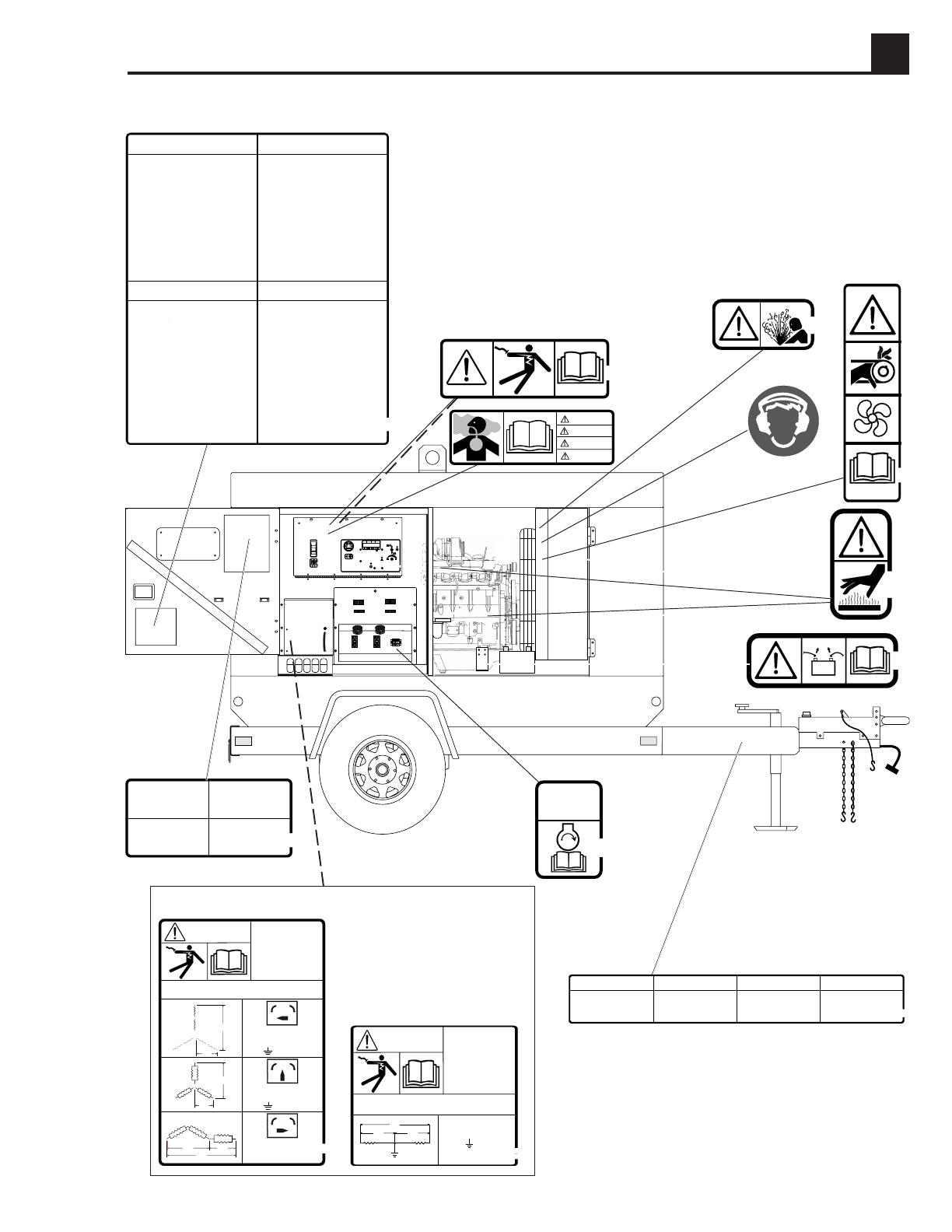
VOR DEM STARTEN
1. BETRIEBSVORSCHRIFT LESEN.
2. GERAT WAAGRECHT STELLEN.
3. RADER BLOCKIEREN.
4. GERAT ERDEN.
5. STAND ALLER FLUSSIGKEITEN PRUFEN.
HANDSTARTEN
1. ALLE AUSSEREN BELASTUNGEN ABSCHALTEN.
2. SPANNUNGSWAHLSCHALTER SETZEN.
3. SPANNUNGSWAHLSCHALTER VERRIEGELN.
4. NOTSTOPKNOPF IN "ON" POSITION SETZEN.
5. MOTORSTARTSCHALTER AUF POSITION "START/LAUF"
DRUCKEN.
6. MOTOR VOLLZIEHT 3 STARTVERSUCHE.
FERNSTART
1. SIEHE BETRIEBSVORSCHRIFT.
ABSCHALTEN
1. ALLE AUSSEREN BELASTUNGEN ABSCHALTEN.
2. MOTORSTARTSCHALTER AUF POSITION "OFF"
DRUCKEN.
3. KRAFTSTOFFTANK FULLEN.
INSTRUCCIONES PARA LA PUESTA EN MARCHA
DE GENERADORES MOVILES
BEFORE STARTING
1. READ OPERATOR'S MANUAL.
2. LEVEL UNIT.
3. BLOCK WHEELS.
4. GROUND UNIT.
5. CHECK ALL FLUID LEVELS.
MANUAL STARTING
1. DISCONNECT ALL EXTERNAL LOADS.
2. SET VOLTAGE SELECTOR SWITCH.
3. LOCK VOLTAGE SELECTOR SWITCH.
4. TURN EMERGENCY STOP BUTTON TO "ON" POSITION.
5. PUSH ENGINE START SWITCH TO
"START/RUN" POSITION.
6. ENGINE WILL MAKE 3 ATTEMPTS TO START.
REMOTE START
1. SEE OPERATOR'S MANUAL.
STOPPING
1. DISCONNECT ALL EXTERNAL LOADS.
2. PUSH ENGINE START SWITCH TO "OFF" POSITION.
3. FILL FUEL TANK.
AVANT LE DEMARRAGE
1. LIRE LA NOTICE D'EMPLOI.
2. NIVELER LA MACHINE.
3. BLOQUER LES ROUES AVEC CALES DE ROUES.
4. METTRE A TERRE LA MACHINE.
5. VERIFIER LE NIVEAU DE TOUS LES FLUIDES.
DEMARRAGE A LA MAIN
1. DECONNECTER TOUS LES REGIMES EXTERNES.
2. REGLER LE COMMUTATEUR DES TENSIONS
D'ALIMENTATION.
3. SERRER LE COMMUTATEUR DES TENSIONS
D'ALIMENTATION.
4. TOURNER LE BOUTON D'ARRET D'URGENCE
A LA POSITION "ON".
5. PRESSER L'INTERRUPTEUR DE DEMARRAGE
DU MOTEUR A LA POSITION "DEMARRAGE/MARCHE".
6. LE MOTEUR S'ESSAYERA DE DEMARRER 3 FOIS.
DEMARRAGE A DISTANCE
1. LIRE LA NOTICE D'EMPLOI.
ARRET
1. DECONNECTER TOUS LES REGIMES EXTERNES.
2. PRESSER L'INTERRUPTEUR DE DEMARRAGE DU
MOTEUR A LA POSTION "OFF".
3. REMPLIR LE RESERVOIR A CARBURANT.
ANTES DEL ARRANQUE
1. LEA EL MANUAL DEL OPERARIO.
2. NIVELE LA UNIDAD.
3. COLOQUE CUNAS DEBAJO DE LAS RUEDAS.
4. CONECTE LA UNIDAD A TIERRA.
5. CONTROLE TODOS LOS LIQUIDOS.
ARRANQUE MANUAL
1. DESCONECTE TODAS LAS CARGAS EXTERNAS.
2. AJUSTE LA LLAVE SELECTORA DE VOLTAJE.
3. BLOQUEE LA LLAVE SELECTORA DE VOLTAJE.
4. GIRE A LA POSICION "ON" EL BOTON DE
PARADA DE EMERGENCIA.
5. OPRIMA A LA POSICION "ARRANQUE/MARCHA" EL
INTERRUPTOR DE ARRANQUE DEL MOTOR.
6. EL MOTOR INTENTARA ARRANCAR 3 VECES.
ARRANQUE REMOTO
1. VEA EL MANUAL DEL OPERARIO.
DETENCION DEL MOTOR
1. DESCONECTE TODAS LAS CARGAS EXTERNAS.
2. OPRIMA A LA POSICION "OFF" EL INTERRUPTOR
DE ARRANQUE DEL MOTOR.
3. LLENE EL TANQUE DE COMBUSTIBLE.
114904
REMOTE START
FERNSTART
ARRANQUE REMOTO
DEMARRAGE A
DISTANCE
114897
DANGER
GEFAHR
PELIGRO
DANGER
EL MANUAL DE OPERACION DEBE
SER RETENIDO EN LA MAQUINA.
CONTACTE A SU DISTRIBUIDOR
WACKER MAS CERCANO PARA
PEDIR UN EJEMPLAR
ADICIONAL.
LA NOTICE D'EMPLOI DOIT
ETRE MUNIE SUR LA MACHINE.
CONTACTER LE DISTRIBUTEUR
WACKER LE PLUS PROCHE
POUR COMMANDER UN
EXEMPLAIRE SUPPLEMENTAIRE.
115096
OPERATOR'S MANUAL MUST BE
STORED ON MACHINE.
REPLACEMENT OPERATOR'S
MANUAL CAN BE ORDERED
THROUGH YOUR LOCAL WACKER
DISTRIBUTOR.
DIE BETRIEBSVORSCHRIFT MUSS
AN DER MASCHINE AUFBEWAHRT
WERDEN. ZUR BESTELLUNG VON
ERSATZBÜCHERN WENDEN SIE
SICH BITTE AN IHREN
ÖRTLICHEN WACKER HÄNDLER.
DANGER PELIGRO
GEFAHR DANGER
TO REDUCE THE RISK OF ELECTRICAL SHOCK,
READ OPERATORS MANUAL.
IMPROPER CONNECTION OF GENERATOR TO A
BUILDING'S ELECTRICAL SYSTEM CAN ALLOW
ELECTICAL CURRENT FROM THE GENERATOR
TO BACKFEED INTO UTILITY LINES.
THIS MAY RESULT IN ELECTROCUTION
OF UTILITY WORKERS, FIRE OR EXPLOSION.
CONNECTIONS TO A BUILDING'S ELECTRICAL
SYSTEM MUST BE MADE BY A QUALIFIED
ELECTRICIAN AND COMPLY WITH ALL
APPLICABLE LAWS AND ELECTRICAL CODES.
BORNES DE CONEXION
RACCORDS TERMINALS
TERMINAL CONNECTIONS
VERBINDUNGSKLEMMEN
L1-L2 = 240V
L1-N = 120V
L2-N = 120V
N -
T1
T2
T4
T3
120V
120V
240V
L1 L2
114994
N
G25
G12
DANGER PELIGRO
GEFAHR DANGER
TO REDUCE THE RISK OF ELECTRICAL SHOCK,
READ OPERATORS MANUAL.
IMPROPER CONNECTION OF GENERATOR TO A
BUILDING'S ELECTRICAL SYSTEM CAN ALLOW
ELECTICAL CURRENT FROM THE GENERATOR
TO BACKFEED INTO UTILITY LINES.
THIS MAY RESULT IN ELECTROCUTION
OF UTILITY WORKERS, FIRE OR EXPLOSION.
CONNECTIONS TO A BUILDING'S ELECTRICAL
SYSTEM MUST BE MADE BY A QUALIFIED
ELECTRICIAN AND COMPLY WITH ALL
APPLICABLE LAWS AND ELECTRICAL CODES.
BORNES DE CONEXION
RACCORDS TERMINALS
TERMINAL CONNECTIONS
VERBINDUNGSKLEMMEN
240
120
480
277
208
120
L1-L2 = 480V L1-N = 277V
L2-L3 = 480V L2-N = 277V
L3-L1 = 480V L3-N = 277V
N-
208
120
240
120
480
277
208
120
L1-L2 = 208V L1-N = 120V
L2-L3 = 208V L2-N = 120V
L3-L1 = 208V L3-N = 120V
N-
240
120
480
277
L1-L3 = 240V
L1-N = 120V
L2-N = ----
L3-N = 120V
114898
T7
L1
T1
T2
L2
T8
T5
T1
T4
T7
N
T12
T10
T9
T6
T11
L1
T3
L3
L1
T7
T1
L2
T8
T2
N
T10
T12
T3
T6
T5
T4
T11
L3
T9
T10
N
T5
T11
T12
T2
T4
T9
L3
T3
T8
T6
L-N
120V
L-N
L-L
120V
L-L
240V
POUR REMORQUE
G - FEUX DE STOP ET DE DIRECTION D
Y - FEUX DE STOP ET DE DIRECTION G
Br -FEUX D'ARRIERE, DE POSITION ET
DE PLAQUE D'IMMATRICULATION
W - MISE A TERRE
L - FREINS ELECTRIQUES
B - CHARGE DE LA BATTERIE
G - RECHTES BREMSLICHT UND BLINKER
Y - LINKES BREMSLICHT UND BLINKER
Br -SCHLUSS-, SEITEN- UND
KENNZEICHENLEUCHTE
W - ERDUNG
L - ELEKTRISCHE BREMSE
B - BATTERIE-LADUNG
ANHÄNGER-VERDRAHTUNG
TRAILER WIRING
G - RIGHT BRAKE LIGHT AND DIRECTIONAL
Y - LEFT BRAKE LIGHT AND DIRECTIONAL
Br -TAIL, SIDE AND LICENSE PLATE LIGHTS
W - GROUND
L - ELECTRIC BRAKES
B - BATTERY CHARGE
DE REMOLQUE
G - LUZ FRENO Y GIRO DERECHA
Y - LUZ FRENO Y GIRO IZQUIERDA
Br -LUZ TRASERA, LATERAL Y PLACA
DE MATRICULA
W - TIERRA
L - FRENOS ELECTRICOS
B - CARGA BATERIA
115681
DISPOSITION DES CABLES CANALISATION ELECTRICA


