Air King ARA36GL Manual de usuario
- Categoría
- Campanas de cocina
- Tipo
- Manual de usuario
Este manual también es adecuado para
La página se está cargando...
La página se está cargando...
La página se está cargando...

- Lámpara control de funcionamiento de la iluminación. (Ref. E).
- Lámparas de control del funcionamiento del motor (Ref. G).
- Pulsador para la lámpara de iluminación (Ref. F ).
Temporización: Para temporizar el funcionamiento de la cam-
pana, una vez seleccionada la velocidad, se deberá presionar
durante dos segundos el botón hasta que el led luminoso par-
padee; entonces empezará a contar hasta 15 minutos.
Una vez transcurrido este tiempo se parará el motor y la luz si
estuviera encendida. En el caso de querer anular la tempori-
zación, presionar una pulsación en el botón temporizado y el
motor dejará de funcionar.
IMPORTANTE: Durante una descarga electroestática (ESD) es
posible que este aparato deje de funcionar. Apague el apara-
to (OFF) y vuelva a encenderlo (ON) y funcionará correcta-
mente. No hay ni habrá posibilidad de riesgo alguno.
MANTENIMIENTO:
• Limpieza: Siempre antes de efectuar cualquier operación
asegurarse de que el interruptor esté en posición de paro.
Limpiar la parte externa con un detergente líquido no corrosivo
y evitar el uso de productos de limpieza abrasivos.
• Cambio de lámpara: Antes de sustituir la lámpara asegu-
rarse de que la campana no esté conectada. Quitar el filtro de
grasa y cambiar la lámpara usando una lámpara de potencia
igual a la que se indica en las características técnicas. Colocar
el filtro nuevamente en su lugar.
IMPORTANTE: En caso de sustitución de las lámparas halóge-
nas, éstas deben ser sustituidas por lámparas con reflector de
aluminio, nunca por lámparas dicroicas, para evitar un sobreca-
lentamiento innecesario en el portalámparas.
• Limpieza del filtro de grasa: En virtud del uso y como
mínimo cada mes, los filtros de grasa deberán ser desmontados
(Fig. 3) y (Fig. 4) y lavados en lavavajillas o en agua caliente y
detergente. En el caso de utilizar lavavajillas, es recomendable
colocarlos en posición vertical para evitar que los restos de
comida se depositen sobre el mismo. Después de haberlos
enjuagado y secado colocar-los nuevamente en su lugar,
actuando de forma inversa al desmontarlos.
GB
ENGLISH
INSTRUCCIONES DE SEGURIDAD:
ADVERTENCIA: DESCONECTE LA CAMPANA DE LA FUENTE
DE ALIMENTACIÓN ANTES DE EMPEZAR A USARLA.
ADVERTENCIA – PARA REDUCIR EL RIESGO DE INCENDIO,
DESCARGA ELÉCTRICA O DAÑO PARA LAS PERSONAS,
OBSERVE LO SIGUIENTE:
• No utilice este extractor con ningún dispositivo de control de
velocidad de estado sólido.
• Utilice este aparato exclusivamente de la forma prevista por el
fabricante. Si tiene alguna pregunta, póngase en contacto con el
fabricante.
• Antes de efectuar servicio o de limpiar el aparato, desconecte la
alimentación en el panel de servicio y bloquee el panel de servicio
para evitar que la alimentación se conecte accidentalmente.
Cuando el medio de desconexión del servicio no pueda bloquear-
se, ajuste de forma segura un dispositivo de advertencia destaca-
do, como por ejemplo, una señal en el panel de servicio.
PRECAUCIÓN – UTILIZAR EXCLUSIVAMENTE PARA VENTILA-
CIÓN GENERAL. NO UTILIZAR PARA LA EXTRACCIÓN DE MATE-
RIALES Y VAPORES PELIGROSOS O EXPLOSIVOS.
PRECAUCIÓN - Para evitar el riesgo de incendio trabaje sólo con
conductos de metal.
ADVERTENCIA – CON EL FIN DE REDUCIR EL RIESGO DE UN
INCENDIO DEBIDO A LA GRASA EN LA P
AR
TE SUPERIOR:
a) Nunca deje los fogones desatendidos cuando cocine a fuego
alto. Los vertidos pueden causar humo y salpicaduras de
grasa que pueden prender fuego. Caliente el aceite lenta-
mente a media o baja temperatura.
b)
∑ Encienda siempre la campana cuando cocine con una
temperatura alta o cuando cocine alimentos flameados (ej: Crepe
Suzette, Cerezas al Jubille, Ternera al pimiento flameado)
c) Limpie los ventiladores frecuentemente. No debe permitir
que se acumule la grasa ni en el ventilador ni en el filtro.
d) Use sartenes del tamaño adecuado. Siempre use utensilios
de cocina apr
opiados para cada fogón.
ADVERTENCIA – PARA REDUCIR EL RIESGO DE DAÑOS PARA
LAS PERSONAS EN CASO DE INCENDIO DE LA GRASA DE LA
PARTE SUPERIOR DE LA CAMPANA, SIGA LOS CONSEJOS
SIGUIENTES:
• SOFOQUE LAS LLAMAS con una tapa que ajuste correcta-
mente, una plata para galletas o bandeja metálica, después apa-
gue el quemador. TENGA CUIDADO PARA EVITAR QUEMADU-
RAS. Si las llamas no se apagan inmediatamente, EVACÚE Y
LLAME A LOS BOMBEROS.
• NO COJA NUNCA UN RECIPIENTE EN LLAMAS – podría que-
marse.
• NO UTILICE AGUA, incluyendo paños de cocina o toallas húme-
dos – podría causar una explosión de vapor violenta.
Utilice un extintor SOLAMENTE si:
• Sabe que tiene un extintor de clase ABC y ya sabe como utili-
zarlo.
• El fuego es pequeño y está localizado en el área donde se ha ini-
ciado.
• Se ha llamado a los bomberos.
• Puede combatir el fuego de espaldas a una salida.
ADVERTENCIA: SE NECESITA UNA CANTIDAD SUFICIENTE
DE AIRE PARA UNA ADECUADA COMBUSTIÓN Y
EXTRACCIÓN DE GASES A TRAVÉS DE LA CHIMENEA DEL
EQUIPO PARA QUEMAR GASOIL, PARA PREVENIR QUE
RETROCEDA. SIGA LAS INSTRUCCIONES Y ESTANDARDS DE
SEGURIDAD DEL FABRICANTE DEL EQUIPO DE
CALEFACCIÓN, COMO LAS PUBLICADAS POR LA
ASOCIACIÓN NACIONAL DE PROTECCIÓN DE INCENDIOS
(NFPA), Y LA SOCIEDAD AMERICANA DE INGENIEROS PARA
CALEFACCIÓN, REFRIGERACIÓN Y AIRE ACONDICIONADO
(ASHRAE) Y LAS AUTORIDADES LOCALES ESPECIALIZADAS.
EL FABRICANTE DECLINA TODA RESPONSABILIDAD EN
CASO DE QUE NO SEAN OBSERVADAS LAS INDICACIONES
DESCRIT
AS P
ARA LA INST
ALACIÓN, MANTENIMIENTO Y USO
ADECUADAS DE LA CAMP
ANA EXTRACTORA.
DECORATIVE EXTRACTOR HOODS
Dear client:
We are sure that the purchase of our extractor hood will fully
satisfy all of your needs. Please read this instruction manual
carefully in order to obtain the best results from the use of the
hood.
IMPORTANT
For our guarantee to be effective, you must present your pur-
chase receipt along with the guarantee certificate. Otherwise,
the guarantee will have no effect.
INSTRUCTIONS FOR INSTALLATION, MAINTENANCE
AND USE
GENERAL INDICATIONS
Before installing and using the hood, be sure that the voltage (V)
and the frequency (Hz) indicated on the feature plate match the
voltage and frequency at the installation site.
The feature plate and technical data are shown on the inside of
the product.
This hood is equipped with an extendible tube which allows it to
be adjusted to the height of the stove.
TECHNICAL CHARACTERISTICS
Voltage and Frequency: 120 V 60 Hz
Total power: 570 W
Three speed motor: 470 W
Lights: 2 x 50 W
INSTALLATION INSTRUCTIONS:
WARNING – TO REDUCE THE RISK OF FIRE,
ELECTRIC SHOCK OR INJURY TO PERSONS,
OBSERVE THE FOLLOWING:
a) Installation Work And Electrical Wiring Must Be Done By
Qualified Person(s) In Accor
dance With All Applicable Codes
And Standards, Including Fire-Rated Construction.
b) Sufficient air is needed for proper combustion and exhaus-
ting of gases through the flue (chimney) of fuel burning equip-
ment to prevent back drafting. Follow the heating equipment
manufacturer’s guideline and safety standards such as those
published by the National Fire Protection Association (NFPA) ,
and the American Society for Heating, Refrigeration and Air
Conditioning Engineers (ASHRAE) , and local code authorities.
c)
When Cutting Or Drilling Into W
all Or Ceiling, Do Not
Damage Electrical Wiring Or Other Hidden Utilities.
d) Ducted Fans Must Always Be Vented To The Outdoors.
e) Use only metal ductwork.
WALL MOUNTING
• Please, remove the polyfoam protection piece before use.
• Connect the plastic conical outlet piece supplied with the
hood (6 inches diameter) to an exhaust pipe connected directly
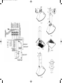
to the outside. (Fig. 1)
• Screw on the connection box following Fig. 1 with the two
1/8" x 11/16" screws supplied in the box of accessories
• The accessories needed to install the hood are inside the
hood.
• Drill holes in the wall using a 1/4" drill bit.
• The plugs and screws need to hang the hood are contained
in the bag of accessories supplied with the hood.
• This fan shall be mounted a minimum of 22 inches above
the heat source.
ELECTRICAL CONNECTION
Important: Be certain all wiring complies with local codes and
the unit is properly grounded.
• Run three wires, two for the power supply and the ground
wire, from the connection box on the canopy to a power con-
nection point near the installation. See Fig. 1A.
• Using connectors for officially approved wiring, connect the
power conductors to the conductors for the fan: black to brown
and white to blue. Connect the grounding wire (green or bare) to
the mass conductor (yellow/green) of the fan distribution box.
ASSEMBLY OF DECORATIVE EXTENDIBLE
TUBE
• Mark the wall at the location of support E (Figure 2) accor-
ding to the heights and specifications shown on the attached jig.
• Drill holes in the wall, place plugs in the holes and attach
support E with screws.
• Place tube A with the extendible part B hanging on the insi-
de, making sure that flange D is correctly lodged in the support
E (Fig. 2).
• Next, secure support G to the upper end of the wall, making
sure that it is properly aligned with the extendible tube. Extend
the movable part of tube B until it reaches support G and con-
nect to the support with the two side screws. (Fig. 5).
CONTROL PANEL
This panel is located on the fr
ont part of the hood and includes:
- 3 position motor control switch (1st, 2nd, and 3rd speed) (Ref. D).
- Lighting control lamp. Fig. 6. (Ref. E).
- Motor control lights. (Ref. G).
60807625.14.09.2004 22/12/04 09:43 Página 8

CAMPANA EXTRACTORA DECORATIVA
Estimado cliente:
Tenemos la certeza que la adquisición de nuestra campana
extractora va a satisfacer plenamente sus necesidades; para ello
le rogamos lea atentamente las instrucciones del manual con lo
cual obtendrá un resultado óptimo en la utilización de la misma.
IMPORTANTE
Para la obtención de nuestra garantía, será imprescindible pre-
sentar la factura de compra de la campana con el certificado de
garantía. Sin este requisito la garantía no tendrá validez.
INSTRUCCIONES PARA LA INSTALACIÓN,
MANUTENCIÓN Y USO
INDICACIONES GENERALES
• Antes de instalar y usar la campana, asegurar que la tensión
(V) y la frecuencia (Hz) indicadas en la placa de características
correspondan a la tensión y la frecuencia del lugar de instalación.
• La placa de características y los datos técnicos se encuen-
tran en el interior del producto.
Esta campana se suministra con un tubo telescópico, que per-
mite ajustarlo según la altura de la cocina.
CARACTERÍSTICAS TÉCNICAS
TENSIÓN y FRECUENCIA: 120 V 60 Hz
POTENCIA TOTAL: 570 W
MOTOR A TRES VELOCIDADES: 470 W
LÁMPARA: 2 x 50 W
INSTRUCCIONES DE INSTALACIÓN:
ADVERTENCIA – PARA REDUCIR EL RIESGO
DE INCENDIO, DESCARGA ELÉCTRICA O
DAÑO PARA LAS PERSONAS, OBSERVE LO
SIGUIENTE:
• El trabajo de instalación y el cableado eléctrico deben ser reali-
zados por personas cualificadas, de acuerdo con todos los códigos
y normas aplicables, incluyendo una construcción ignífuga.
• Es necesario air
e suficiente para la combustión correcta y la
extracción de los gases a través del canal de humos (chimenea)
del equipo de combustión para evitar el contratiro. Siga las ins-
trucciones del fabricante del equipo de calefacción y las normas
de seguridad como las publicadas por la Asociación nacional de
protección contra el fuego (NFPA) y la Sociedad americana de
ingenier
os de calefacción, refrigeración y aire acondicionado
(ASHRAE) y las Autoridades r
eguladoras locales.
• Cuando corte o taladre en la pared o en el techo, no dañe el
cableado eléctrico ni otras instalaciones de servicios ocultas.
• Los extractores entubados deben ventilarse siempre al exterior.
•
Utilice sólo conductos metálicos.
MONTAJE Y FIJACIÓN A LA PARED.
• Por favor, retirar las piezas de protección de espuma antes de
utilizar.
• Conectar la pieza plástica cónica de salida, suministrada con
la campana (diámetro 6") a un producto de evacuación conecta-
do directamente con el exterior. (Fig.1)
• Atornillar la caja de conexiones según Fig. 1 con los dos torni-
llos de 1/8" x 11/16" que se suministran en la bolsa de accesorios.
• Los accesorios necesarios para la instalación de la campana
se encuentran en el interior de la misma.
• Realizar los orificios en la pared usando una broca de 6 mm.
• En la bolsa de accesorios que se suministran con la campa-
na, encontrará los tacos y los tornillos necesarios para la fijación
de la misma.
• Este ventilador debe montarse a un mínimo de 22 pulgadas
sobre la fuente de calor.
CABLEADO
IMPORTANTE: Asegurase que todo el cableado cumple con las
leyes locales y que el aparato esté correctamente puesto a tierra.
• Extienda tres cables, dos de alimentación y uno de tierra,
desde la caja de empalmes de la campana hasta una caja de
empalmes próxima al lugar de instalación. Ver Fig. 1 Ref A
• Utilizando conectores para cables homologados, conecte los
conductores de alimentación a los conductores del ventilador:
negro con marrón y blanco con azul. Conecte el conductor de
toma de tierra (verde o desnudo) al conductor de masa (amari-
llo/verde) de la caja de distribución del ventilador.
MONTAJE DEL TUBO TELESCÓPICO EMBELLE-
CEDOR:
• Marcar en la pared la posición del soporte E (Fig. 2), según
cotas y especificaciones de la plantilla adjunta.
• Efectuar los agujeros en la pared, aplicar los tacos en los ori-
ficios y fijar el soporte E con los tornillos.
• Poner el tubo A con la parte telescópica B en su interior, ase-
gurándose que la pestaña D esté correctamente alojada en el
soporte E (Fig. 2).
• A continuación debe fijarse el soporte G en el extremo supe-
rior de la pared asegurándose de que la alineación respecto al
tubo telescópico es la correcta. Extender la parte móvil del tubo
B hasta alcanzar el soporte G y fijarlo con dicho soporte median
-
te los dos tornillos laterales. (Fig. 5).
PANEL DE MANDOS
Este panel está situado en la parte fr
ontal de la campana y
compr
ende:
- 3 pulsadores para el control del motor (posición 1ª, 2ª y 3ª
velocidad) (ref. D).
E
ESPAÑOL
- Light switch (Ref. F).
TIMING: To operate the canopy timer, having selected the speed,
press the button for two seconds until the LED light blinks. The
timer will then work for 15 minutes.
At the end of this time, the motor will stop and the light will go
out. If it is still on, and you wish to cancel the timing, press the
timer button once and the motor will stop.
IMPORTANT: During an electrostatic discharge (ESD) it is possi-
ble that the device will stop working. By switching the device
OFF an ON the device will again work as intended. There is no
risk and no risk will appear.
MAINTENANCE
• Cleaning: Disconnect the power before cleaning or servi-
cing. Clean the external part with a mild, liquid detergent and
avoid the use of abrasive cleaning products.
• Changing the light: Before changing the light make sure
that the hood is not connected.
Remove the grease filter and replace the light with a light bulb no
more powerful than that specified in the Technical
Characteristics. Place the filter in position.
IMPORTANT: If the halogen lamps need replacing, they must be
replaced by lamps with an aluminium reflector, never dichroic
lamps, to avoid unnecessary overheating in the lamp holders.
• Cleaning the grease filter: Depending on use, and at least
once a month, the grease filters should be disassembled (Fig. 3)
and (fig. 4) and cleaned in a dishwasher or with hot soapy water.
If washed in a dishwasher they should be placed in an upright
position to prevent food remains from falling on them. After rin-
sing and drying, replace the filters by following the steps for
disassembly in reverse order.
IMPORTANT SAFETY INSTRUCTIONS:
WARNING: DISCONNECT THE RANGE HOOD FROM POWER
SUPPLY BEFORE SERVICING.
WARNING – TO REDUCE THE RISK OF FIRE, ELECTRIC SHOCK
OR INJURY TO PERSONS, OBSERVE THE FOLLOWING:
a) Do not use this fan with any solid state speed control device.
b) Use this unit only in the manner intended by the manufacturer. If
you have questions, contact the manufacturer.
c) Before servicing or cleaning unit, switch power off at service
panel and lock service panel to prevent power from being switched
on accidentally. When the service disconnecting means cannot be
locked, securely fasten a prominent warning device, such as a tag
to the service panel.
CAUTION: FOR GENERAL VENTILATING USE ONLY. DO NOT
USE TO EXHAUST HAZARDOUS OR EXPLOSIVE MATERIALS
AND VAPORS.
CAUTION: To reduce the risk of fire, use only metal duct work.
WARNING – TO REDUCE THE RISK OF A RANGE TOP GREASE
FIRE:
a) Never leave surface units unattended at high settings. Boilovers
cause smoking and greasy spillovers that may ignite. Heat oils
slowly on low or medium settings.
b) Always turn hood ON when cooking at high heat or when
flambeing food (i.e. Crepes Suzette, Cherries Jubilee,
Peppercorn Beef Flambé)
c) Clean ventilating fans frequently. Grease should not be allowed
to accumulate on fan or filter
.
d)
Use proper pan size. Always use cookware appropiate for the
size of the surface element.
WARNING – TO REDUCE THE RISK OF INJURY TO PERSONS
IN THE EVENT OF A RANGE TOP GREASE FIRE, OBSERVE
THE FOLLOWING:
a) SMOTHER FLAMES with a close-fitting lid, cookie sheet, or
metal tray, then turn off the burner. BE CAREFUL TO PREVENT
BURNS. If the flames do not go out immediately
, EV
ACUATE AND
CALL THE FIRE DEPARTMENT.
b) NEVER PICK UP A FLAMING PAN – you may be burned.
c) DO NOT USE WATER, including wet dishclothes or towels –
a violent steam explosion will result.
d) Use an extinguisher ONLY if:
1. You know you have a Class ABC extinguisher, and you
already know how to operate it.
2. The fire is small and contained in the area where it started.
3. The Fire Department is being called.
4. You can fight the fire with your back to an exit.
WARNING – SUFFICIENT AIR IS NEEDED FOR PROPER COM-
BUSTION AND EXHAUSTING OF GASES THROUGH THE FLUE
(CHIMNEY) OF FUEL BURNING EQUIPMENT TO PREVENT
BACK DRAFTING. FOLLOW THE HEATING EQUIPMENT
MANUFACTURER'S GUIDELINES AND SAFETY STANDARDS
SUCH AS THOSE PUBLISHED BY NATIONAL FIRE
PROTECTION ASSOCIATION (NFPA), AND THE AMERICAN
SOCIETY FOR HEATING, REFRIGERATION AND AIR
CONDITIONNING ENGINEERS (ASHRAE), AND LOCAL CODE
AHTHORITIES.
THE MANUFACTURER DECLINES ALL LIABILITY IN CASES
WHERE THE INSTRUCTIONS FOR THE APPROPRIA
TE
INST
ALLA
TION, MAINTENANCE AND USE OF THE
EXTRACTOR HOOD ARE NOT OBSER
VED.
60807625.14.09.2004 22/12/04 09:43 Página 10
La página se está cargando...
Transcripción de documentos
60807625.14.09.2004 22/12/04 09:43 Página 8 GB ENGLISH DECORATIVE EXTRACTOR HOODS Dear client: We are sure that the purchase of our extractor hood will fully satisfy all of your needs. Please read this instruction manual carefully in order to obtain the best results from the use of the hood. IMPORTANT For our guarantee to be effective, you must present your purchase receipt along with the guarantee certificate. Otherwise, the guarantee will have no effect. INSTRUCTIONS FOR INSTALLATION, MAINTENANCE AND USE GENERAL INDICATIONS Before installing and using the hood, be sure that the voltage (V) and the frequency (Hz) indicated on the feature plate match the voltage and frequency at the installation site. The feature plate and technical data are shown on the inside of the product. This hood is equipped with an extendible tube which allows it to be adjusted to the height of the stove. TECHNICAL CHARACTERISTICS Voltage and Frequency: 120 V 60 Hz Total power: 570 W Three speed motor: 470 W Lights: 2 x 50 W INSTALLATION INSTRUCTIONS: WARNING – TO REDUCE THE RISK OF FIRE, ELECTRIC SHOCK OR INJURY TO PERSONS, OBSERVE THE FOLLOWING: a) Installation Work And Electrical Wiring Must Be Done By Qualified Person(s) In Accordance With All Applicable Codes And Standards, Including Fire-Rated Construction. b) Sufficient air is needed for proper combustion and exhausting of gases through the flue (chimney) of fuel burning equipment to prevent back drafting. Follow the heating equipment manufacturer’s guideline and safety standards such as those published by the National Fire Protection Association (NFPA) , and the American Society for Heating, Refrigeration and Air Conditioning Engineers (ASHRAE) , and local code authorities. c) When Cutting Or Drilling Into Wall Or Ceiling, Do Not Damage Electrical Wiring Or Other Hidden Utilities. d) Ducted Fans Must Always Be Vented To The Outdoors. e) Use only metal ductwork. WALL MOUNTING • Please, remove the polyfoam protection piece before use. • Connect the plastic conical outlet piece supplied with the hood (6 inches diameter) to an exhaust pipe connected directly to the outside. (Fig. 1) • Screw on the connection box following Fig. 1 with the two 1/8" x 11/16" screws supplied in the box of accessories • The accessories needed to install the hood are inside the hood. • Drill holes in the wall using a 1/4" drill bit. • The plugs and screws need to hang the hood are contained in the bag of accessories supplied with the hood. • This fan shall be mounted a minimum of 22 inches above the heat source. ELECTRICAL CONNECTION Important: Be certain all wiring complies with local codes and the unit is properly grounded. • Run three wires, two for the power supply and the ground wire, from the connection box on the canopy to a power connection point near the installation. See Fig. 1A. • Using connectors for officially approved wiring, connect the power conductors to the conductors for the fan: black to brown and white to blue. Connect the grounding wire (green or bare) to the mass conductor (yellow/green) of the fan distribution box. ASSEMBLY OF DECORATIVE EXTENDIBLE TUBE • Mark the wall at the location of support E (Figure 2) according to the heights and specifications shown on the attached jig. • Drill holes in the wall, place plugs in the holes and attach support E with screws. • Place tube A with the extendible part B hanging on the inside, making sure that flange D is correctly lodged in the support E (Fig. 2). • Next, secure support G to the upper end of the wall, making sure that it is properly aligned with the extendible tube. Extend the movable part of tube B until it reaches support G and connect to the support with the two side screws. (Fig. 5). CONTROL PANEL This panel is located on the front part of the hood and includes: - 3 position motor control switch (1st, 2nd, and 3rd speed) (Ref. D). - Lighting control lamp. Fig. 6. (Ref. E). - Motor control lights. (Ref. G). - Lámpara control de funcionamiento de la iluminación. (Ref. E). - Lámparas de control del funcionamiento del motor (Ref. G). - Pulsador para la lámpara de iluminación (Ref. F ). Temporización: Para temporizar el funcionamiento de la campana, una vez seleccionada la velocidad, se deberá presionar durante dos segundos el botón hasta que el led luminoso parpadee; entonces empezará a contar hasta 15 minutos. Una vez transcurrido este tiempo se parará el motor y la luz si estuviera encendida. En el caso de querer anular la temporización, presionar una pulsación en el botón temporizado y el motor dejará de funcionar. IMPORTANTE: Durante una descarga electroestática (ESD) es posible que este aparato deje de funcionar. Apague el aparato (OFF) y vuelva a encenderlo (ON) y funcionará correctamente. No hay ni habrá posibilidad de riesgo alguno. MANTENIMIENTO: • Limpieza: Siempre antes de efectuar cualquier operación asegurarse de que el interruptor esté en posición de paro. INSTRUCCIONES DE SEGURIDAD: ADVERTENCIA: DESCONECTE LA CAMPANA DE LA FUENTE DE ALIMENTACIÓN ANTES DE EMPEZAR A USARLA. ADVERTENCIA – PARA REDUCIR EL RIESGO DE INCENDIO, DESCARGA ELÉCTRICA O DAÑO PARA LAS PERSONAS, OBSERVE LO SIGUIENTE: • No utilice este extractor con ningún dispositivo de control de velocidad de estado sólido. • Utilice este aparato exclusivamente de la forma prevista por el fabricante. Si tiene alguna pregunta, póngase en contacto con el fabricante. • Antes de efectuar servicio o de limpiar el aparato, desconecte la alimentación en el panel de servicio y bloquee el panel de servicio para evitar que la alimentación se conecte accidentalmente. Cuando el medio de desconexión del servicio no pueda bloquearse, ajuste de forma segura un dispositivo de advertencia destacado, como por ejemplo, una señal en el panel de servicio. PRECAUCIÓN – UTILIZAR EXCLUSIVAMENTE PARA VENTILACIÓN GENERAL. NO UTILIZAR PARA LA EXTRACCIÓN DE MATERIALES Y VAPORES PELIGROSOS O EXPLOSIVOS. PRECAUCIÓN - Para evitar el riesgo de incendio trabaje sólo con conductos de metal. ADVERTENCIA – CON EL FIN DE REDUCIR EL RIESGO DE UN INCENDIO DEBIDO A LA GRASA EN LA PARTE SUPERIOR: a) Nunca deje los fogones desatendidos cuando cocine a fuego alto. Los vertidos pueden causar humo y salpicaduras de grasa que pueden prender fuego. Caliente el aceite lentamente a media o baja temperatura. b) ∑ Encienda siempre la campana cuando cocine con una temperatura alta o cuando cocine alimentos flameados (ej: Crepe Suzette, Cerezas al Jubille, Ternera al pimiento flameado) c) Limpie los ventiladores frecuentemente. No debe permitir que se acumule la grasa ni en el ventilador ni en el filtro. d) Use sartenes del tamaño adecuado. Siempre use utensilios de cocina apropiados para cada fogón. Limpiar la parte externa con un detergente líquido no corrosivo y evitar el uso de productos de limpieza abrasivos. • Cambio de lámpara: Antes de sustituir la lámpara asegurarse de que la campana no esté conectada. Quitar el filtro de grasa y cambiar la lámpara usando una lámpara de potencia igual a la que se indica en las características técnicas. Colocar el filtro nuevamente en su lugar. IMPORTANTE: En caso de sustitución de las lámparas halógenas, éstas deben ser sustituidas por lámparas con reflector de aluminio, nunca por lámparas dicroicas, para evitar un sobrecalentamiento innecesario en el portalámparas. • Limpieza del filtro de grasa: En virtud del uso y como mínimo cada mes, los filtros de grasa deberán ser desmontados (Fig. 3) y (Fig. 4) y lavados en lavavajillas o en agua caliente y detergente. En el caso de utilizar lavavajillas, es recomendable colocarlos en posición vertical para evitar que los restos de comida se depositen sobre el mismo. Después de haberlos enjuagado y secado colocar-los nuevamente en su lugar, actuando de forma inversa al desmontarlos. ADVERTENCIA – PARA REDUCIR EL RIESGO DE DAÑOS PARA LAS PERSONAS EN CASO DE INCENDIO DE LA GRASA DE LA PARTE SUPERIOR DE LA CAMPANA, SIGA LOS CONSEJOS SIGUIENTES: • SOFOQUE LAS LLAMAS con una tapa que ajuste correctamente, una plata para galletas o bandeja metálica, después apague el quemador. TENGA CUIDADO PARA EVITAR QUEMADURAS. Si las llamas no se apagan inmediatamente, EVACÚE Y LLAME A LOS BOMBEROS. • NO COJA NUNCA UN RECIPIENTE EN LLAMAS – podría quemarse. • NO UTILICE AGUA, incluyendo paños de cocina o toallas húmedos – podría causar una explosión de vapor violenta. Utilice un extintor SOLAMENTE si: • Sabe que tiene un extintor de clase ABC y ya sabe como utilizarlo. • El fuego es pequeño y está localizado en el área donde se ha iniciado. • Se ha llamado a los bomberos. • Puede combatir el fuego de espaldas a una salida. ADVERTENCIA: SE NECESITA UNA CANTIDAD SUFICIENTE DE AIRE PARA UNA ADECUADA COMBUSTIÓN Y EXTRACCIÓN DE GASES A TRAVÉS DE LA CHIMENEA DEL EQUIPO PARA QUEMAR GASOIL, PARA PREVENIR QUE RETROCEDA. SIGA LAS INSTRUCCIONES Y ESTANDARDS DE SEGURIDAD DEL FABRICANTE DEL EQUIPO DE CALEFACCIÓN, COMO LAS PUBLICADAS POR LA ASOCIACIÓN NACIONAL DE PROTECCIÓN DE INCENDIOS (NFPA), Y LA SOCIEDAD AMERICANA DE INGENIEROS PARA CALEFACCIÓN, REFRIGERACIÓN Y AIRE ACONDICIONADO (ASHRAE) Y LAS AUTORIDADES LOCALES ESPECIALIZADAS. EL FABRICANTE DECLINA TODA RESPONSABILIDAD EN CASO DE QUE NO SEAN OBSERVADAS LAS INDICACIONES DESCRITAS PARA LA INSTALACIÓN, MANTENIMIENTO Y USO ADECUADAS DE LA CAMPANA EXTRACTORA. 60807625.14.09.2004 22/12/04 09:43 Página 10 E ESPAÑOL CAMPANA EXTRACTORA DECORATIVA Estimado cliente: Tenemos la certeza que la adquisición de nuestra campana extractora va a satisfacer plenamente sus necesidades; para ello le rogamos lea atentamente las instrucciones del manual con lo cual obtendrá un resultado óptimo en la utilización de la misma. IMPORTANTE Para la obtención de nuestra garantía, será imprescindible presentar la factura de compra de la campana con el certificado de garantía. Sin este requisito la garantía no tendrá validez. INSTRUCCIONES PARA LA INSTALACIÓN, MANUTENCIÓN Y USO INDICACIONES GENERALES • Antes de instalar y usar la campana, asegurar que la tensión (V) y la frecuencia (Hz) indicadas en la placa de características correspondan a la tensión y la frecuencia del lugar de instalación. • La placa de características y los datos técnicos se encuentran en el interior del producto. Esta campana se suministra con un tubo telescópico, que permite ajustarlo según la altura de la cocina. CARACTERÍSTICAS TÉCNICAS TENSIÓN y FRECUENCIA: 120 V 60 Hz POTENCIA TOTAL: 570 W MOTOR A TRES VELOCIDADES: 470 W LÁMPARA: 2 x 50 W MONTAJE Y FIJACIÓN A LA PARED. • Por favor, retirar las piezas de protección de espuma antes de utilizar. • Conectar la pieza plástica cónica de salida, suministrada con la campana (diámetro 6") a un producto de evacuación conectado directamente con el exterior. (Fig.1) • Atornillar la caja de conexiones según Fig. 1 con los dos tornillos de 1/8" x 11/16" que se suministran en la bolsa de accesorios. • Los accesorios necesarios para la instalación de la campana se encuentran en el interior de la misma. • Realizar los orificios en la pared usando una broca de 6 mm. • En la bolsa de accesorios que se suministran con la campana, encontrará los tacos y los tornillos necesarios para la fijación de la misma. • Este ventilador debe montarse a un mínimo de 22 pulgadas sobre la fuente de calor. CABLEADO IMPORTANTE: Asegurase que todo el cableado cumple con las leyes locales y que el aparato esté correctamente puesto a tierra. • Extienda tres cables, dos de alimentación y uno de tierra, desde la caja de empalmes de la campana hasta una caja de empalmes próxima al lugar de instalación. Ver Fig. 1 Ref A • Utilizando conectores para cables homologados, conecte los conductores de alimentación a los conductores del ventilador: negro con marrón y blanco con azul. Conecte el conductor de toma de tierra (verde o desnudo) al conductor de masa (amarillo/verde) de la caja de distribución del ventilador. INSTRUCCIONES DE INSTALACIÓN: MONTAJE DEL TUBO TELESCÓPICO EMBELLECEDOR: ADVERTENCIA – PARA REDUCIR EL RIESGO DE INCENDIO, DESCARGA ELÉCTRICA O DAÑO PARA LAS PERSONAS, OBSERVE LO SIGUIENTE: • Marcar en la pared la posición del soporte E (Fig. 2), según cotas y especificaciones de la plantilla adjunta. • Efectuar los agujeros en la pared, aplicar los tacos en los orificios y fijar el soporte E con los tornillos. • Poner el tubo A con la parte telescópica B en su interior, asegurándose que la pestaña D esté correctamente alojada en el soporte E (Fig. 2). • A continuación debe fijarse el soporte G en el extremo superior de la pared asegurándose de que la alineación respecto al tubo telescópico es la correcta. Extender la parte móvil del tubo B hasta alcanzar el soporte G y fijarlo con dicho soporte mediante los dos tornillos laterales. (Fig. 5). • El trabajo de instalación y el cableado eléctrico deben ser realizados por personas cualificadas, de acuerdo con todos los códigos y normas aplicables, incluyendo una construcción ignífuga. • Es necesario aire suficiente para la combustión correcta y la extracción de los gases a través del canal de humos (chimenea) del equipo de combustión para evitar el contratiro. Siga las instrucciones del fabricante del equipo de calefacción y las normas de seguridad como las publicadas por la Asociación nacional de protección contra el fuego (NFPA) y la Sociedad americana de ingenieros de calefacción, refrigeración y aire acondicionado (ASHRAE) y las Autoridades reguladoras locales. • Cuando corte o taladre en la pared o en el techo, no dañe el cableado eléctrico ni otras instalaciones de servicios ocultas. • Los extractores entubados deben ventilarse siempre al exterior. • Utilice sólo conductos metálicos. PANEL DE MANDOS Este panel está situado en la parte frontal de la campana y comprende: - 3 pulsadores para el control del motor (posición 1ª, 2ª y 3ª velocidad) (ref. D). - Light switch (Ref. F). TIMING: To operate the canopy timer, having selected the speed, press the button for two seconds until the LED light blinks. The timer will then work for 15 minutes. At the end of this time, the motor will stop and the light will go out. If it is still on, and you wish to cancel the timing, press the timer button once and the motor will stop. IMPORTANT: During an electrostatic discharge (ESD) it is possible that the device will stop working. By switching the device OFF an ON the device will again work as intended. There is no risk and no risk will appear. MAINTENANCE • Cleaning: Disconnect the power before cleaning or servicing. Clean the external part with a mild, liquid detergent and avoid the use of abrasive cleaning products. IMPORTANT SAFETY INSTRUCTIONS: WARNING: DISCONNECT THE RANGE HOOD FROM POWER SUPPLY BEFORE SERVICING. WARNING – TO REDUCE THE RISK OF FIRE, ELECTRIC SHOCK OR INJURY TO PERSONS, OBSERVE THE FOLLOWING: a) Do not use this fan with any solid state speed control device. b) Use this unit only in the manner intended by the manufacturer. If you have questions, contact the manufacturer. c) Before servicing or cleaning unit, switch power off at service panel and lock service panel to prevent power from being switched on accidentally. When the service disconnecting means cannot be locked, securely fasten a prominent warning device, such as a tag to the service panel. CAUTION: FOR GENERAL VENTILATING USE ONLY. DO NOT USE TO EXHAUST HAZARDOUS OR EXPLOSIVE MATERIALS AND VAPORS. CAUTION: To reduce the risk of fire, use only metal duct work. WARNING – TO REDUCE THE RISK OF A RANGE TOP GREASE FIRE: a) Never leave surface units unattended at high settings. Boilovers cause smoking and greasy spillovers that may ignite. Heat oils slowly on low or medium settings. b) Always turn hood ON when cooking at high heat or when flambeing food (i.e. Crepes Suzette, Cherries Jubilee, Peppercorn Beef Flambé) c) Clean ventilating fans frequently. Grease should not be allowed to accumulate on fan or filter. d) Use proper pan size. Always use cookware appropiate for the size of the surface element. WARNING – TO REDUCE THE RISK OF INJURY TO PERSONS IN THE EVENT OF A RANGE TOP GREASE FIRE, OBSERVE THE FOLLOWING: a) SMOTHER FLAMES with a close-fitting lid, cookie sheet, or metal tray, then turn off the burner. BE CAREFUL TO PREVENT BURNS. If the flames do not go out immediately, EVACUATE AND • Changing the light: Before changing the light make sure that the hood is not connected. Remove the grease filter and replace the light with a light bulb no more powerful than that specified in the Technical Characteristics. Place the filter in position. IMPORTANT: If the halogen lamps need replacing, they must be replaced by lamps with an aluminium reflector, never dichroic lamps, to avoid unnecessary overheating in the lamp holders. • Cleaning the grease filter: Depending on use, and at least once a month, the grease filters should be disassembled (Fig. 3) and (fig. 4) and cleaned in a dishwasher or with hot soapy water. If washed in a dishwasher they should be placed in an upright position to prevent food remains from falling on them. After rinsing and drying, replace the filters by following the steps for disassembly in reverse order. CALL THE FIRE DEPARTMENT. b) NEVER PICK UP A FLAMING PAN – you may be burned. c) DO NOT USE WATER, including wet dishclothes or towels – a violent steam explosion will result. d) Use an extinguisher ONLY if: 1. You know you have a Class ABC extinguisher, and you already know how to operate it. 2. The fire is small and contained in the area where it started. 3. The Fire Department is being called. 4. You can fight the fire with your back to an exit. WARNING – SUFFICIENT AIR IS NEEDED FOR PROPER COMBUSTION AND EXHAUSTING OF GASES THROUGH THE FLUE (CHIMNEY) OF FUEL BURNING EQUIPMENT TO PREVENT BACK DRAFTING. FOLLOW THE HEATING EQUIPMENT MANUFACTURER'S GUIDELINES AND SAFETY STANDARDS SUCH AS THOSE PUBLISHED BY NATIONAL FIRE PROTECTION ASSOCIATION (NFPA), AND THE AMERICAN SOCIETY FOR HEATING, REFRIGERATION AND AIR CONDITIONNING ENGINEERS (ASHRAE), AND LOCAL CODE AHTHORITIES. THE MANUFACTURER DECLINES ALL LIABILITY IN CASES WHERE THE INSTRUCTIONS FOR THE APPROPRIATE INSTALLATION, MAINTENANCE AND USE OF THE EXTRACTOR HOOD ARE NOT OBSERVED.-
 1
1
-
 2
2
-
 3
3
-
 4
4
-
 5
5
-
 6
6


Air King ARA36GL Manual de usuario
- Categoría
- Campanas de cocina
- Tipo
- Manual de usuario
- Este manual también es adecuado para
en otros idiomas
- français: Air King ARA36GL Manuel utilisateur
- English: Air King ARA36GL User manual
Artículos relacionados
-
Air King ALI36SS Use And Handling Instructions
-
-
-
-
-
-
-
-
-