Air King Barcelona Collection Mallorca Use And Handling Instructions
- Categoría
- Campanas de cocina
- Tipo
- Use And Handling Instructions
La página se está cargando...

DECORATIVE EXTRACTOR HOODS
Dear client:
We are sure that the purchase of our extractor hood will fully
satisfy all of your needs. Please read this instruction manual
carefully in order to obtain the best results from the use of the
hood.
IMPORTANT
For our guarantee to be effective, you must present your pur-
chase receipt along with the guarantee certificate. Otherwise,
the guarantee will have no effect.
INSTRUCTIONS FOR INSTALLATION, MAINTENANCE
AND USE
GENERAL INDICATIONS
Before installing and using the hood, be sure that the voltage (V)
and the frequency (Hz) indicated on the feature plate match the
voltage and frequency at the installation site.
The feature plate and technical data are shown on the inside of
the product.
This hood is equipped with an extendible tube which allows it to
be adjusted to the height of the stove.
TECHNICAL CHARACTERISTICS
Voltage and Frequency: 120 V 60 Hz
Total power: 570 W
Three speed motor: 470 W
Lights: 2 x 50 W
INSTALLATION INSTRUCTIONS:
WARNING – TO REDUCE THE RISK OF FIRE,
ELECTRIC SHOCK OR INJURY TO PERSONS,
OBSERVE THE FOLLOWING:
a)Installation Work And Electrical Wiring Must Be Done By
Qualified Person(s) In Accordance With All Applicable Codes
And Standards, Including Fire-Rated Construction.
b)Sufficient air is needed for proper combustion and exhausting
of gases through the flue (chimney) of fuel burning equipment
to prevent back drafting. Follow the heating equipment manu
facturer’s guideline and safety standards such as those publis
hed by the National Fire Protection Association (NFPA) , and
the American Society for Heating, Refrigeration and Air
Conditioning Engineers (ASHRAE) , and local code authorities.
c)When Cutting Or Drilling Into Wall Or Ceiling, Do Not Damage
Electrical Wiring Or Other Hidden Utilities.
d)Ducted Fans Must Always Be Vented To The Outdoors.
e)Use only metal ductwork.
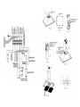
ASSEMBLY AND CEILING MOUNTING.
• Please, remove the polyfoam protection piece before use.
• The accessories needed to install the hood are inside the
hood.
• Use the two screws to attach the reducer pipe H to the upper
platen (Fig. 1). Connect the 4,5” non-flammable pipe to the ope-
ning in the ceiling.
• Confirm that the ceiling will support the weight of the hood.
Drill 4 holes in the ceiling using a 5/6”. Bit and insert the plugs
(Fig. 2).
• Adjust the length of the telescopic structure and attached the
two pieces with 8 screws and washers. Bear in mind that the
minimum distance from working surface to the base of the hood
should not be less than 22” (Fig. 3).
• Attach the previously adjusted telescopic structure to the cei-
ling using 4 screws and washers (Fig. 4).
• Introduce the J pipe with the grate on the upper part and
attach the telescopic structure using 2 screws (Fig. 4).
• Introduce the k pipe and keep it raised (Fig. 5).
• Affix the hood to the telescopic structure using the nuts and
washers (Fig. 5).
• Lower the K pipe attach it to the hood with 2 screws (Fig. 5)
ELECTRICAL CONNECTION
Important: Be certain all wiring complies with local codes and
the unit is properly grounded.
• Run three wires, two for the power supply and the ground wire,
from the connection box on the canopy to a power connection
point near the installation. See Fig. 3
• Using connectors for officially approved wiring, connect the
power conductors to the conductors for the fan: black to brown
and white to blue. Connect the grounding wire (green or bare) to
the mass conductor (yellow/green) of the fan distribution box.
CONTROL PANEL
This panel is located on the front part of the hood and includes:
- 3 position motor control switch (1st, 2nd, and 3rd speed) (Ref. D).
- Lighting control lamp. Fig. 6. (Ref. E).
- Motor control lights. (Ref. G).
- Light switch (Ref. F).
TIMING: To operate the canopy timer, having selected the speed,
press the button for two seconds until the LED light blinks. The
timer will then work for 15 minutes.
At the end of this time, the motor will stop and the light will go
out. If it is still on, and you wish to cancel the timing, press the
timer button once and the motor will stop.
Una vez transcurrido este tiempo se parará el motor y la luz si
estuviera encendida. En el caso de querer anular la temporiza-
ción, presionar una pulsación en el botón temporizado y el motor
dejará de funcionar.
IMPORTANTE: Durante una descarga electroestática (ESD) es
posible que este aparato deje de funcionar. Apague el aparato
(OFF) y vuelva a encenderlo (ON) y funcionará correctamente.
No hay ni habrá posibilidad de riesgo alguno.
MANTENIMIENTO:
• Limpieza: Siempre antes de efectuar cualquier operación ase-
gurarse de que el interruptor esté en posición de paro. Limpiar
la parte externa con un detergente líquido no corrosivo y evitar
el uso de productos de limpieza abrasivos.
• Cambio de lámpara: Antes de sustituir la lámpara asegurarse
de que la campana no esté conectada. Quitar el filtro de grasa y
cambiar la lámpara usando una lámpara de potencia igual a la que
se indica en las características técnicas. Colocar el filtro nueva-
mente en su lugar.
IMPORTANTE: En caso de sustitución de las lámparas halógenas,
éstas deben ser sustituidas por lámparas con reflector de aluminio,
nunca por lámparas dicroicas, para evitar un sobrecalentamiento
innecesario en el portalámparas.
• Limpieza del filtro de grasa: En virtud del uso y como míni-
mo cada mes, los filtros de grasa deberán ser desmontados (Fig.
3) y (Fig. 4) y lavados en lavavajillas o en agua caliente y deter-
gente. En el caso de utilizar lavavajillas, es recomendable colo-
carlos en posición vertical para evitar que los restos de comida
se depositen sobre el mismo. Después de haberlos enjuagado y
secado colocar-los nuevamente en su lugar, actuando de forma
inversa al desmontarlos.
GB
ENGLISH
INSTRUCCIONES DE SEGURIDAD:
ADVERTENCIA: DESCONECTE LA CAMPANA DE LA FUENTE
DE ALIMENTACIÓN ANTES DE EMPEZAR A USARLA.
ADVERTENCIA – PARA REDUCIR EL RIESGO DE INCENDIO,
DESCARGA ELÉCTRICA O DAÑO PARA LAS PERSONAS,
OBSERVE LO SIGUIENTE:
• No utilice este extractor con ningún dispositivo de control de
velocidad de estado sólido.
• Utilice este aparato exclusivamente de la forma prevista por el
fabricante. Si tiene alguna pregunta, póngase en contacto con el
fabricante.
• Antes de efectuar servicio o de limpiar el aparato, desconecte la
alimentación en el panel de servicio y bloquee el panel de servicio
para evitar que la alimentación se conecte accidentalmente.
Cuando el medio de desconexión del servicio no pueda bloquear-
se, ajuste de forma segura un dispositivo de advertencia destaca-
do, como por ejemplo, una señal en el panel de servicio.
PRECAUCIÓN – UTILIZAR EXCLUSIVAMENTE PARA VENTILA-
CIÓN GENERAL. NO UTILIZAR PARA LA EXTRACCIÓN DE MATE-
RIALES Y VAPORES PELIGROSOS O EXPLOSIVOS.
PRECAUCIÓN - Para evitar el riesgo de incendio trabaje sólo con
conductos de metal.
ADVERTENCIA – CON EL FIN DE REDUCIR EL RIESGO DE UN
INCENDIO DEBIDO A LA GRASA EN LA PARTE SUPERIOR:
a) Nunca deje los fogones desatendidos cuando cocine a fuego
alto. Los vertidos pueden causar humo y salpicaduras de
grasa que pueden prender fuego. Caliente el aceite lenta-
mente a media o baja temperatura.
b) Encienda siempre la campana cuando cocine con una tem
peratura alta o cuando cocine alimentos flameados (ej: Crepe
Suzette, Cerezas al Jubille, Ternera al pimiento flameado)
c) Limpie los ventiladores frecuentemente. No debe permitir
que se acumule la grasa ni en el ventilador ni en el filtro.
d) Use sartenes del tamaño adecuado. Siempre use utensilios
de cocina apropiados para cada fogón.
ADVERTENCIA – PARA REDUCIR EL RIESGO DE DAÑOS PARA
LAS PERSONAS EN CASO DE INCENDIO DE LA GRASA DE LA
PARTE SUPERIOR DE LA CAMPANA, SIGA LOS CONSEJOS
SIGUIENTES:
• SOFOQUE LAS LLAMAS con una tapa que ajuste correctamen-
te, una plata para galletas o bandeja metálica, después apague el
quemador. TENGA CUIDADO PARA EVITAR QUEMADURAS. Si las
llamas no se apagan inmediatamente, EVACÚE Y LLAME A LOS
BOMBEROS.
• NO COJA NUNCA UN RECIPIENTE EN LLAMAS – podría que-
marse.
• NO UTILICE AGUA, incluyendo paños de cocina o toallas húme-
dos – podría causar una explosión de vapor violenta.
Utilice un extintor SOLAMENTE si:
• Sabe que tiene un extintor de clase ABC y ya sabe como utili-
zarlo.
• El fuego es pequeño y está localizado en el área donde se ha ini-
ciado.
• Se ha llamado a los bomberos.
• Puede combatir el fuego de espaldas a una salida.
ADVERTENCIA: SE NECESITA UNA CANTIDAD SUFICIENTE
DE AIRE PARA UNA ADECUADA COMBUSTIÓN Y
EXTRACCIÓN DE GASES A TRAVÉS DE LA CHIMENEA DEL
EQUIPO PARA QUEMAR GASOIL, PARA PREVENIR QUE
RETROCEDA. SIGA LAS INSTRUCCIONES Y ESTANDARDS DE
SEGURIDAD DEL FABRICANTE DEL EQUIPO DE
CALEFACCIÓN, COMO LAS PUBLICADAS POR LA
ASOCIACIÓN NACIONAL DE PROTECCIÓN DE INCENDIOS
(NFPA), Y LA SOCIEDAD AMERICANA DE INGENIEROS PARA
CALEFACCIÓN, REFRIGERACIÓN Y AIRE ACONDICIONADO
(ASHRAE) Y LAS AUTORIDADES LOCALES ESPECIALIZADAS.
EL FABRICANTE DECLINA TODA RESPONSABILIDAD EN
CASO DE QUE NO SEAN OBSERVADAS LAS INDICACIONES
DESCRITAS PARA LA INSTALACIÓN, MANTENIMIENTO Y USO
ADECUADAS DE LA CAMPANA EXTRACTORA.
60807585.14.09.2004 22/12/04 10:04 Página 8
CAMPANA EXTRACTORA DECORATIVA
Estimado cliente:
Tenemos la certeza que la adquisición de nuestra campana
extractora va a satisfacer plenamente sus necesidades; para ello
le rogamos lea atentamente las instrucciones del manual con lo
cual obtendrá un resultado óptimo en la utilización de la misma.
IMPORTANTE
Para la obtención de nuestra garantía, será imprescindible pre-
sentar la factura de compra de la campana con el certificado de
garantía. Sin este requisito la garantía no tendrá validez.
INSTRUCCIONES PARA LA INSTALACIÓN,
MANUTENCIÓN Y USO
INDICACIONES GENERALES
• Antes de instalar y usar la campana, asegurar que la tensión
(V) y la frecuencia (Hz) indicadas en la placa de características
correspondan a la tensión y la frecuencia del lugar de instala-
ción.
• La placa de características y los datos técnicos se encuentran
en el interior del producto.
Esta campana se suministra con un tubo telescópico, que per-
mite ajustarlo según la altura de la cocina.
CARACTERÍSTICAS TÉCNICAS
TENSIÓN y FRECUENCIA: 120 V 60 Hz
POTENCIA TOTAL: 570 W
MOTOR A TRES VELOCIDADES: 470 W
LÁMPARA: 2 x 50 W
INSTRUCCIONES DE INSTALACIÓN:
ADVERTENCIA – PARA REDUCIR EL RIESGO
DE INCENDIO, DESCARGA ELÉCTRICA O
DAÑO PARA LAS PERSONAS, OBSERVE LO
SIGUIENTE:
• El trabajo de instalación y el cableado eléctrico deben ser rea-
lizados por personas cualificadas, de acuerdo con todos los
códigos y normas aplicables, incluyendo una construcción igní-
fuga.
• Es necesario aire suficiente para la combustión correcta y la
extracción de los gases a través del canal de humos (chimenea)
del equipo de combustión para evitar el contratiro. Siga las ins-
trucciones del fabricante del equipo de calefacción y las normas
de seguridad como las publicadas por la Asociación nacional de
protección contra el fuego (NFPA) y la Sociedad americana de
ingenieros de calefacción, refrigeración y aire acondicionado
(ASHRAE) y las Autoridades reguladoras locales.
• Cuando corte o taladre en la pared o en el techo, no dañe el
cableado eléctrico ni otras instalaciones de servicios ocultas.
• Los extractores entubados deben ventilarse siempre al exterior.
• Utilice sólo conductos metálicos.
MONTAJE Y FIJACIÓN AL TECHO.
• Por favor, retirar las piezas de protección de espuma antes de
utilizar.
• Los accesorios necesarios para la instalación de la campana
se encuentra en el interior de la misma.
• Fijar el tubo reductor H a la pletina superior mediante 2 torni-
llos (Fig. 1). Conectar un tubo ininflamable de 4,5” a la apertura
practicada en el techo.
• Comprobar que el techo aguanta el peso de la campana.
Realizar los 4 orificios en el techo usando una broca de 5/6” e
insertar los tacos. (Fig. 2).
• Regular la longitud de la estructura telescópica y fijar las dos
piezas con 8 tornillos y arandelas. Tener en cuenta que la dis-
tancia mínima desde el plano de trabajo a la base de la campa-
na no debe ser inferior a 22” (Fig. 3).
• Fijar el techo la estructura telescópica anteriormente regulada
mediante 4 tornillos y arandelas. (Fig. 4).
• Introducir el tubo J con la rejilla en la parte superior y fijarlo a
la estructura telescópica mediante 2 tornillos. (Fig. 4).
• Introducir el tubo K y mantenerlo levantado (Fig. 5).
• Fijar la campana a la estructura telescópica mediante las 4
tuercas y arandelas. (Fig. 5).
• Bajar el tubo K y fijarlo a la campana con 2 tornillos. (Fig. 5).
CABLEADO
IMPORTANTE: Asegurase que todo el cableado cumple con las
leyes locales y que el aparato esté correctamente puesto a tierra.
• Extienda tres cables, dos de alimentación y uno de tierra,
desde la caja de empalmes de la campana hasta una caja de
empalmes próxima al lugar de instalación. Ver Fig. 3
• Utilizando conectores para cables homologados, conecte los
conductores de alimentación a los conductores del ventilador:
negro con marrón y blanco con azul. Conecte el conductor de
toma de tierra (verde o desnudo) al conductor de masa (amari-
llo/verde) de la caja de distribución del ventilador.
PANEL DE MANDOS
Este panel está situado en la parte frontal de la campana y com-
prende:
- 3 pulsadores para el control del motor (posición 1ª, 2ª y 3ª velo-
cidad) (ref. D).
- Lámpara control de funcionamiento de la iluminación. (Ref. E).
- Lámparas de control del funcionamiento del motor (Ref. G).
- Pulsador para la lámpara de iluminación (Ref. F ).
Temporización: Para temporizar el funcionamiento de la campa-
na, una vez seleccionada la velocidad, se deberá presionar
durante dos segundos el botón hasta que el led luminoso par-
padee; entonces empezará a contar hasta 15 minutos.
E
ESPAÑOL
IMPORTANT: During an electrostatic discharge (ESD) it is possi-
ble that the device will stop working. By switching the device
OFF an ON the device will again work as intended. There is no
risk and no risk will appear.
MAINTENANCE
• Cleaning: Disconnect the power before cleaning or servicing.
Clean the external part with a mild, liquid detergent and avoid
the use of abrasive cleaning products.
• Changing the light: Before changing the light make sure that
the hood is not connected.
Remove the grease filter and replace the light with a light bulb no
more powerful than that specified in the Technical
Characteristics. Place the filter in position.
IMPORTANT: If the halogen lamps need replacing, they must be
replaced by lamps with an aluminium reflector, never dichroic
lamps, to avoid unnecessary overheating in the lamp holders.
• Cleaning the grease filter: Depending on use, and at least
once a month, the grease filters should be disassembled (Fig. 3)
and (fig. 4) and cleaned in a dishwasher or with hot soapy water.
If washed in a dishwasher they should be placed in an upright
position to prevent food remains from falling on them. After rin-
sing and drying, replace the filters by following the steps for
disassembly in reverse order.
IMPORTANT SAFETY INSTRUCTIONS:
WARNING: DISCONNECT THE RANGE HOOD FROM POWER
SUPPLY BEFORE SERVICING.
WARNING – TO REDUCE THE RISK OF FIRE, ELECTRIC
SHOCK OR INJURY TO PERSONS, OBSERVE THE
FOLLOWING:
a) Do not use this fan with any solid state speed control device.
b) Use this unit only in the manner intended by the manufacturer.
If you have questions, contact the manufacturer.
c) Before servicing or cleaning unit, switch power off at service
panel and lock service panel to prevent power from being switched
on accidentally. When the service disconnecting means cannot be
locked, securely fasten a prominent warning device, such as a tag
to the service panel.
CAUTION: FOR GENERAL VENTILATING USE ONLY. DO NOT
USE TO EXHAUST HAZARDOUS OR EXPLOSIVE MATERIALS
AND VAPORS.
CAUTION: To reduce the risk of fire, use only metal duct work.
WARNING – TO REDUCE THE RISK OF A RANGE TOP GREASE
FIRE:
a) Never leave surface units unattended at high settings.
Boilovers cause smoking and greasy spillovers that may ignite.
Heat oils slowly on low or medium settings.
b) Always turn hood ON when cooking at high heat or when
flambeing food (i.e. Crepes Suzette, Cherries Jubilee,
Peppercorn Beef Flambé)
c) Clean ventilating fans frequently. Grease should not be allowed
to accumulate on fan or filter.
d) Use proper pan size. Always use cookware appropiate for the
size of the surface element.
WARNING – TO REDUCE THE RISK OF INJURY TO PERSONS
IN THE EVENT OF A RANGE TOP GREASE FIRE, OBSERVE
THE FOLLOWING:
a) SMOTHER FLAMES with a close-fitting lid, cookie sheet, or
metal tray, then turn off the burner. BE CAREFUL TO PREVENT
BURNS. If the flames do not go out immediately, EVACUATE AND
CALL THE FIRE DEPARTMENT.
b) NEVER PICK UP A FLAMING PAN – you may be burned.
c) DO NOT USE WATER, including wet dishclothes or towels – a
violent steam explosion will result.
d) Use an extinguisher ONLY if:
1. You know you have a Class ABC extinguisher, and you already
know how to operate it.
2. The fire is small and contained in the area where it started.
3. The Fire Department is being called.
4. You can fight the fire with your back to an exit.
WARNING – SUFFICIENT AIR IS NEEDED FOR PROPER COM-
BUSTION AND EXHAUSTING OF GASES THROUGH THE FLUE
(CHIMNEY) OF FUEL BURNING EQUIPMENT TO PREVENT
BACK DRAFTING. FOLLOW THE HEATING EQUIPMENT
MANUFACTURER'S GUIDELINES AND SAFETY STANDARDS
SUCH AS THOSE PUBLISHED BY NATIONAL FIRE
PROTECTION ASSOCIATION (NFPA), AND THE AMERICAN
SOCIETY FOR HEATING, REFRIGERATION AND AIR
CONDITIONNING ENGINEERS (ASHRAE), AND LOCAL CODE
AHTHORITIES.
THE MANUFACTURER DECLINES ALL LIABILITY IN CASES
WHERE THE INSTRUCTIONS FOR THE APPROPRIATE
INSTALLATION, MAINTENANCE AND USE OF THE
EXTRACTOR HOOD ARE NOT OBSERVED.
60807585.14.09.2004 22/12/04 10:04 Página 10
DECORATIVE EXTRACTOR HOODS
Dear client:
We are sure that the purchase of our extractor hood will fully
satisfy all of your needs. Please read this instruction manual
carefully in order to obtain the best results from the use of the
hood.
IMPORTANT
For our guarantee to be effective, you must present your pur-
chase receipt along with the guarantee certificate. Otherwise,
the guarantee will have no effect.
INSTRUCTIONS FOR INSTALLATION, MAINTENANCE
AND USE
GENERAL INDICATIONS
Before installing and using the hood, be sure that the voltage (V)
and the frequency (Hz) indicated on the feature plate match the
voltage and frequency at the installation site.
The feature plate and technical data are shown on the inside of
the product.
This hood is equipped with an extendible tube which allows it to
be adjusted to the height of the stove.
TECHNICAL CHARACTERISTICS
Voltage and Frequency: 120 V 60 Hz
Total power: 570 W
Three speed motor: 470 W
Lights: 2 x 50 W
INSTALLATION INSTRUCTIONS:
WARNING – TO REDUCE THE RISK OF FIRE,
ELECTRIC SHOCK OR INJURY TO PERSONS,
OBSERVE THE FOLLOWING:
a)Installation Work And Electrical Wiring Must Be Done By
Qualified Person(s) In Accordance With All Applicable Codes
And Standards, Including Fire-Rated Construction.
b)Sufficient air is needed for proper combustion and exhausting
of gases through the flue (chimney) of fuel burning equipment
to prevent back drafting. Follow the heating equipment manu
facturer’s guideline and safety standards such as those publis
hed by the National Fire Protection Association (NFPA) , and
the American Society for Heating, Refrigeration and Air
Conditioning Engineers (ASHRAE) , and local code authorities.
c)When Cutting Or Drilling Into Wall Or Ceiling, Do Not Damage
Electrical Wiring Or Other Hidden Utilities.
d)Ducted Fans Must Always Be Vented To The Outdoors.
e)Use only metal ductwork.
ASSEMBLY AND CEILING MOUNTING.
• Please, remove the polyfoam protection piece before use.
• The accessories needed to install the hood are inside the
hood.
• Use the two screws to attach the reducer pipe H to the upper
platen (Fig. 1). Connect the 4,5” non-flammable pipe to the ope-
ning in the ceiling.
• Confirm that the ceiling will support the weight of the hood.
Drill 4 holes in the ceiling using a 5/6”. Bit and insert the plugs
(Fig. 2).
• Adjust the length of the telescopic structure and attached the
two pieces with 8 screws and washers. Bear in mind that the
minimum distance from working surface to the base of the hood
should not be less than 22” (Fig. 3).
• Attach the previously adjusted telescopic structure to the cei-
ling using 4 screws and washers (Fig. 4).
• Introduce the J pipe with the grate on the upper part and
attach the telescopic structure using 2 screws (Fig. 4).
• Introduce the k pipe and keep it raised (Fig. 5).
• Affix the hood to the telescopic structure using the nuts and
washers (Fig. 5).
• Lower the K pipe attach it to the hood with 2 screws (Fig. 5)
ELECTRICAL CONNECTION
Important: Be certain all wiring complies with local codes and
the unit is properly grounded.
• Run three wires, two for the power supply and the ground wire,
from the connection box on the canopy to a power connection
point near the installation. See Fig. 3
• Using connectors for officially approved wiring, connect the
power conductors to the conductors for the fan: black to brown
and white to blue. Connect the grounding wire (green or bare) to
the mass conductor (yellow/green) of the fan distribution box.
CONTROL PANEL
This panel is located on the front part of the hood and includes:
- 3 position motor control switch (1st, 2nd, and 3rd speed) (Ref. D).
- Lighting control lamp. Fig. 6. (Ref. E).
- Motor control lights. (Ref. G).
- Light switch (Ref. F).
TIMING: To operate the canopy timer, having selected the speed,
press the button for two seconds until the LED light blinks. The
timer will then work for 15 minutes.
At the end of this time, the motor will stop and the light will go
out. If it is still on, and you wish to cancel the timing, press the
timer button once and the motor will stop.
Una vez transcurrido este tiempo se parará el motor y la luz si
estuviera encendida. En el caso de querer anular la temporiza-
ción, presionar una pulsación en el botón temporizado y el motor
dejará de funcionar.
IMPORTANTE: Durante una descarga electroestática (ESD) es
posible que este aparato deje de funcionar. Apague el aparato
(OFF) y vuelva a encenderlo (ON) y funcionará correctamente.
No hay ni habrá posibilidad de riesgo alguno.
MANTENIMIENTO:
• Limpieza: Siempre antes de efectuar cualquier operación ase-
gurarse de que el interruptor esté en posición de paro. Limpiar
la parte externa con un detergente líquido no corrosivo y evitar
el uso de productos de limpieza abrasivos.
• Cambio de lámpara: Antes de sustituir la lámpara asegurarse
de que la campana no esté conectada. Quitar el filtro de grasa y
cambiar la lámpara usando una lámpara de potencia igual a la que
se indica en las características técnicas. Colocar el filtro nueva-
mente en su lugar.
IMPORTANTE: En caso de sustitución de las lámparas halógenas,
éstas deben ser sustituidas por lámparas con reflector de aluminio,
nunca por lámparas dicroicas, para evitar un sobrecalentamiento
innecesario en el portalámparas.
• Limpieza del filtro de grasa: En virtud del uso y como míni-
mo cada mes, los filtros de grasa deberán ser desmontados (Fig.
3) y (Fig. 4) y lavados en lavavajillas o en agua caliente y deter-
gente. En el caso de utilizar lavavajillas, es recomendable colo-
carlos en posición vertical para evitar que los restos de comida
se depositen sobre el mismo. Después de haberlos enjuagado y
secado colocar-los nuevamente en su lugar, actuando de forma
inversa al desmontarlos.
GB
ENGLISH
INSTRUCCIONES DE SEGURIDAD:
ADVERTENCIA: DESCONECTE LA CAMPANA DE LA FUENTE
DE ALIMENTACIÓN ANTES DE EMPEZAR A USARLA.
ADVERTENCIA – PARA REDUCIR EL RIESGO DE INCENDIO,
DESCARGA ELÉCTRICA O DAÑO PARA LAS PERSONAS,
OBSERVE LO SIGUIENTE:
• No utilice este extractor con ningún dispositivo de control de
velocidad de estado sólido.
• Utilice este aparato exclusivamente de la forma prevista por el
fabricante. Si tiene alguna pregunta, póngase en contacto con el
fabricante.
• Antes de efectuar servicio o de limpiar el aparato, desconecte la
alimentación en el panel de servicio y bloquee el panel de servicio
para evitar que la alimentación se conecte accidentalmente.
Cuando el medio de desconexión del servicio no pueda bloquear-
se, ajuste de forma segura un dispositivo de advertencia destaca-
do, como por ejemplo, una señal en el panel de servicio.
PRECAUCIÓN – UTILIZAR EXCLUSIVAMENTE PARA VENTILA-
CIÓN GENERAL. NO UTILIZAR PARA LA EXTRACCIÓN DE MATE-
RIALES Y VAPORES PELIGROSOS O EXPLOSIVOS.
PRECAUCIÓN - Para evitar el riesgo de incendio trabaje sólo con
conductos de metal.
ADVERTENCIA – CON EL FIN DE REDUCIR EL RIESGO DE UN
INCENDIO DEBIDO A LA GRASA EN LA PARTE SUPERIOR:
a) Nunca deje los fogones desatendidos cuando cocine a fuego
alto. Los vertidos pueden causar humo y salpicaduras de
grasa que pueden prender fuego. Caliente el aceite lenta-
mente a media o baja temperatura.
b) Encienda siempre la campana cuando cocine con una tem
peratura alta o cuando cocine alimentos flameados (ej: Crepe
Suzette, Cerezas al Jubille, Ternera al pimiento flameado)
c) Limpie los ventiladores frecuentemente. No debe permitir
que se acumule la grasa ni en el ventilador ni en el filtro.
d) Use sartenes del tamaño adecuado. Siempre use utensilios
de cocina apropiados para cada fogón.
ADVERTENCIA – PARA REDUCIR EL RIESGO DE DAÑOS PARA
LAS PERSONAS EN CASO DE INCENDIO DE LA GRASA DE LA
PARTE SUPERIOR DE LA CAMPANA, SIGA LOS CONSEJOS
SIGUIENTES:
• SOFOQUE LAS LLAMAS con una tapa que ajuste correctamen-
te, una plata para galletas o bandeja metálica, después apague el
quemador. TENGA CUIDADO PARA EVITAR QUEMADURAS. Si las
llamas no se apagan inmediatamente, EVACÚE Y LLAME A LOS
BOMBEROS.
• NO COJA NUNCA UN RECIPIENTE EN LLAMAS – podría que-
marse.
• NO UTILICE AGUA, incluyendo paños de cocina o toallas húme-
dos – podría causar una explosión de vapor violenta.
Utilice un extintor SOLAMENTE si:
• Sabe que tiene un extintor de clase ABC y ya sabe como utili-
zarlo.
• El fuego es pequeño y está localizado en el área donde se ha ini-
ciado.
• Se ha llamado a los bomberos.
• Puede combatir el fuego de espaldas a una salida.
ADVERTENCIA: SE NECESITA UNA CANTIDAD SUFICIENTE
DE AIRE PARA UNA ADECUADA COMBUSTIÓN Y
EXTRACCIÓN DE GASES A TRAVÉS DE LA CHIMENEA DEL
EQUIPO PARA QUEMAR GASOIL, PARA PREVENIR QUE
RETROCEDA. SIGA LAS INSTRUCCIONES Y ESTANDARDS DE
SEGURIDAD DEL FABRICANTE DEL EQUIPO DE
CALEFACCIÓN, COMO LAS PUBLICADAS POR LA
ASOCIACIÓN NACIONAL DE PROTECCIÓN DE INCENDIOS
(NFPA), Y LA SOCIEDAD AMERICANA DE INGENIEROS PARA
CALEFACCIÓN, REFRIGERACIÓN Y AIRE ACONDICIONADO
(ASHRAE) Y LAS AUTORIDADES LOCALES ESPECIALIZADAS.
EL FABRICANTE DECLINA TODA RESPONSABILIDAD EN
CASO DE QUE NO SEAN OBSERVADAS LAS INDICACIONES
DESCRITAS PARA LA INSTALACIÓN, MANTENIMIENTO Y USO
ADECUADAS DE LA CAMPANA EXTRACTORA.
60807585.14.09.2004 22/12/04 10:04 Página 8
La página se está cargando...
La página se está cargando...
La página se está cargando...
Transcripción de documentos
GB E ESPAÑOL ENGLISH DECORATIVE CAMPANA EXTRACTORA EXTRACTORDECORATIVA HOODS Estimado cliente: Dear client:la certeza que la adquisición de nuestra campana Tenemos We are sure the purchase of oursusextractor hood para will fully extractora va that a satisfacer plenamente necesidades; ello satisfy all of your needs. Please read this instruction le rogamos lea atentamente las instrucciones del manualmanual con lo carefully in order to obtain óptimo the bestenresults from the of the cual obtendrá un resultado la utilización deuse la misma. hood. IMPORTANTE Para la obtención de nuestra garantía, será imprescindible preIMPORTANT sentar factura detocompra de la campana conpresent el certificado de For ourlaguarantee be effective, you must your purgarantía. Sin este requisito la garantía no tendrá validez. chase receipt along with the guarantee certificate. Otherwise, the guarantee will have no effect. INSTRUCCIONES PARA LA INSTALACIÓN, MANUTENCIÓN Y USO INSTRUCTIONS FOR INSTALLATION, MAINTENANCE INDICACIONES GENERALES AND USE • Antes de instalar y usar la campana, asegurar que la tensión (V) y la frecuencia (Hz) indicadas en la placa de características GENERAL correspondan INDICATIONS a la tensión y la frecuencia del lugar de instalaBefore installing and using the hood, be sure that the voltage (V) ción. frequency (Hz) indicated the feature match the •and Lathe placa de características y losondatos técnicosplate se encuentran voltage and frequency at the installation site. en el interior del producto. The feature plate technical are shown on the que insideperof Esta campana se and suministra condata un tubo telescópico, the product. mite ajustarlo según la altura de la cocina. This hood is equipped with an extendible tube which allows it to CARACTERÍSTICAS be adjusted to the heightTÉCNICAS of the stove. TENSIÓN y FRECUENCIA: 120 V 60 Hz POTENCIA TOTAL: 570 W TECHNICAL MOTOR A TRESCHARACTERISTICS VELOCIDADES: 470 W Voltage and2Frequency: LÁMPARA: x 50 W 120 V 60 Hz Total power: 570 W Three speed motor: 470DE W INSTALACIÓN: INSTRUCCIONES Lights: 2 x 50 W ADVERTENCIA – PARA REDUCIR EL RIESGO DE INCENDIO,INSTRUCTIONS: DESCARGA ELÉCTRICA O INSTALLATION DAÑO PARA LAS PERSONAS, OBSERVE LO SIGUIENTE: TO REDUCE THE RISK FIRE, •WARNING El trabajo de–instalación y el cableado eléctricoOF deben ser reaELECTRIC SHOCKcualificadas, OR INJURY TO PERSONS, lizados por personas de acuerdo con todos los OBSERVE THEaplicables, FOLLOWING: códigos y normas incluyendo una construcción ignía) Installation Work And Electrical Wiring Must Be Done By fuga. Qualified Person(s) In Accordance All Applicable Codes • Es necesario aire suficiente para laWith combustión correcta y la And Standards, Including Fire-Rated Construction. extracción de los gases a través del canal de humos (chimenea) b)Sufficient aircombustión is needed forpara proper andSiga exhausting del equipo de evitarcombustion el contratiro. las insof gases del through the flue fuel burningy las equipment trucciones fabricante del(chimney) equipo deofcalefacción normas prevent back Follow the equipment manu detoseguridad comodrafting. las publicadas por heating la Asociación nacional de facturer’s contra guideline and safety standards such asamericana those publis protección el fuego (NFPA) y la Sociedad de hed by thedeNational Fire Protection Association (NFPA) , and ingenieros calefacción, refrigeración y aire acondicionado the American Society for Heating, Refrigeration (ASHRAE) y las Autoridades reguladoras locales. and Air Conditioning code authorities. • Cuando corteEngineers o taladre (ASHRAE) en la pared, and o enlocal el techo, no dañe el c) When Cutting Or niDrilling Wall Or Ceiling, Do Notocultas. Damage cableado eléctrico otras Into instalaciones de servicios Wiring Orentubados Other Hidden •Electrical Los extractores debenUtilities. ventilarse siempre al exterior. •d)Ducted Utilice sólo metálicos. Fansconductos Must Always Be Vented To The Outdoors. e) Use only metal ductwork. MONTAJE Y FIJACIÓN AL TECHO. • Por favor, retirar las piezas de protección de espuma antes de ASSEMBLY AND CEILING MOUNTING. utilizar. •• Please, remove the polyfoampara protection piece before use. Los accesorios necesarios la instalación de la campana •seThe accessories neededdetola install encuentra en el interior misma.the hood are inside the hood. • Fijar el tubo reductor H a la pletina superior mediante 2 torni• Use the1).two screws un to attach the reducerdepipe upper llos (Fig. Conectar tubo ininflamable 4,5”H atolathe apertura platen (Fig. en 1). elConnect practicada techo. the 4,5” non-flammable pipe to the opening in the ceiling. • Comprobar que el techo aguanta el peso de la campana. • Confirmlosthat the ceiling support the una weight of the hood.e Realizar 4 orificios en elwilltecho usando broca de 5/6” Drill 4 holes in the(Fig. ceiling insertar los tacos. 2). using a 5/6”. Bit and insert the plugs (Fig. 2). la longitud de la estructura telescópica y fijar las dos • Regular •piezas Adjustcon the8length of the telescopicTener structure and attached the tornillos y arandelas. en cuenta que la distwo pieces with 8 screws anddewashers. in mind the tancia mínima desde el plano trabajo aBear la base de la that campaminimum distance fromaworking na no debe ser inferior 22” (Fig.surface 3). to the base of the hood should be less than 22” (Fig. 3). • Fijar elnottecho la estructura telescópica anteriormente regulada • Attach the previously adjusted telescopic mediante 4 tornillos y arandelas. (Fig. 4). structure to the ceiusing 4 screws •lingIntroducir el tubo and J conwashers la rejilla(Fig. en la4).parte superior y fijarlo a •la Introduce J pipe with the grate on the(Fig. upper estructura the telescópica mediante 2 tornillos. 4). part and attach the telescopic usinglevantado 2 screws(Fig. (Fig.5). 4). • Introducir el tubo K structure y mantenerlo Introduce the k pipe keep it raised (Fig. 5).mediante las 4 • Fijar la campana a laand estructura telescópica • Affix the hood to the structure using the nuts and tuercas y arandelas. (Fig.telescopic 5). washers • Bajar el(Fig. tubo5).K y fijarlo a la campana con 2 tornillos. (Fig. 5). • Lower the K pipe attach it to the hood with 2 screws (Fig. 5) CABLEADO ELECTRICAL CONNECTION IMPORTANTE: Asegurase que todo el cableado cumple con las Important: Be certain all wiring complies with local codes and leyes locales y que el aparato esté correctamente puesto a tierra. the unit is properly grounded. • Extienda tres cables, dos de alimentación y uno de tierra, • Run three wires, two for the power supply and the ground wire, desde la caja de empalmes de la campana hasta una caja de from the connection box on the canopy to a power connection empalmes próxima al lugar de instalación. Ver Fig. 3 point near the installation. See Fig. 3 • Utilizando conectores para cables homologados, conecte los • Using connectors for officially approved wiring, connect the conductores de alimentación a los conductores del ventilador: power conductors the conductors the fan:elblack to brown negro con marrón to y blanco con azul.for Conecte conductor de and to blue. Connect the grounding wire (green or bare) to tomawhite de tierra (verde o desnudo) al conductor de masa (amarithe mass conductor (yellow/green) of the fan distribution box. llo/verde) de la caja de distribución del ventilador. CONTROL PANEL DE PANEL MANDOS This panel is located onen thelafront of the and includes: Este está situado partepart frontal de hood la campana y com- 3 position motor control switch (1st, 2nd, and 3rd speed) (Ref. D). prende: control Fig. 6.del(Ref. E). (posición 1ª, 2ª y 3ª velo- 3Lighting pulsadores paralamp. el control motor - Motor(ref. control cidad) D). lights. (Ref. G). Light switch (Ref.de F).funcionamiento de la iluminación. (Ref. E). - Lámpara control To operate thedel canopy timer, havingdelselected the speed, -TIMING: Lámparas de control funcionamiento motor (Ref. G). the button two seconds until the(Ref. LED Flight -press Pulsador para laforlámpara de iluminación ). blinks. The timer will then work 15 minutes. Temporización: Parafor temporizar el funcionamiento de la campaAt the this time, the motor will stopseanddeberá the light will go na, unaendvezof seleccionada la velocidad, presionar out. If it dos is stillsegundos on, and you wish hasta to cancel timing, pressparthe durante el botón que the el led luminoso timer button onceempezará and the motor will hasta stop. 15 minutos. padee; entonces a contar IMPORTANT: Una vez transcurrido During aneste electrostatic tiempo sedischarge parará el (ESD) motor ityislapossiluz si ble that the device will working. By switching the device estuviera encendida. En stop el caso de querer anular la temporizaOFF ON theuna device will again intended. There is no ción, an presionar pulsación en elwork botónastemporizado y el motor risk anddenofuncionar. risk will appear. dejará IMPORTANTE: Durante una descarga electroestática (ESD) es MAINTENANCE que este aparatothe deje de funcionar. Apagueorelservicing. aparato •posible Cleaning: Disconnect power before cleaning (OFF) a encenderlo funcionará correctamente. Clean ythevuelva external part with a(ON) mild,y liquid detergent and avoid No hay posibilidad riesgo alguno. the use niof habrá abrasive cleaningde products. • Changing the light: Before changing the light make sure that the hood is not connected. MANTENIMIENTO: Remove the grease anddereplace thecualquier light withoperación a light bulbaseno • Limpieza: Siemprefilter antes efectuar more powerful than that specified in the Technical gurarse de que el interruptor esté en posición de paro. Limpiar Characteristics. Place the filter in position. la parte externa con un detergente líquido no corrosivo y evitar IMPORTANT: If the halogen lamps need replacing, they must be el uso de by productos de limpieza abrasivos. replaced lamps with an aluminium reflector, never dichroic •lamps, Cambio de lámpara: Antesoverheating de sustituir inla the lámpara to avoid unnecessary lamp asegurarse holders. de que la campana no esté conectada. Quitar filtroand de at grasa • Cleaning the grease filter: Depending on eluse, leasty cambiar la lámpara usando una lámpara de potencia igual a la que se indica en las características técnicas. Colocar el filtro nuevamente en su lugar. IMPORTANT SAFETY INSTRUCTIONS: WARNING: DISCONNECT THE RANGE HOOD FROM POWER INSTRUCCIONES DE SEGURIDAD: SUPPLY BEFORE SERVICING. ADVERTENCIA: DESCONECTE LA CAMPANA DE LA FUENTE WARNING – TO REDUCE THE RISK OF FIRE, ELECTRIC DE ALIMENTACIÓN ANTES DE EMPEZAR A USARLA. SHOCK OR INJURY TO PERSONS, OBSERVE THE ADVERTENCIA – PARA REDUCIR EL RIESGO DE INCENDIO, FOLLOWING: DESCARGA ELÉCTRICA O DAÑO PARA LAS PERSONAS, a) Do not LO useSIGUIENTE: this fan with any solid state speed control device. OBSERVE • NoUse utilice esteonly extractor ningún dispositivo control de b) this unit in the con manner intended by the de manufacturer. estado sólido. Ifvelocidad you havedequestions, contact the manufacturer. • Utilice este aparato exclusivamente de la forma prevista por el c) Before Si servicing or cleaning unit,póngase switch power off at service fabricante. tiene alguna pregunta, en contacto con el panel and lock service panel to prevent power from being switched fabricante. •onAntes de efectuar servicio o de limpiar el aparato, desconecte la accidentally. When the service disconnecting means cannot be alimentación en elfasten panelade servicio warning y bloqueedevice, el panel de as servicio locked, securely prominent such a tag para la alimentación se conecte accidentalmente. to the evitar serviceque panel. Cuando el medio de desconexión del servicio no pueda bloquearse, ajuste deFOR formaGENERAL segura unVENTILATING dispositivo deUSE advertencia destacaCAUTION: ONLY. DO NOT do, por ejemplo,HAZARDOUS una señal en OR el panel de servicio. USEcomo TO EXHAUST EXPLOSIVE MATERIALS AND VAPORS. – UTILIZAR EXCLUSIVAMENTE PARA VENTILAPRECAUCIÓN CIÓN GENERAL. NO UTILIZAR LA EXTRACCIÓN MATECAUTION: To reduce the risk ofPARA fire, use only metal ductDEwork. RIALES Y VAPORES PELIGROSOS O EXPLOSIVOS. PRECAUCIÓN Para evitarTHE el riesgo sólo con WARNING – TO- REDUCE RISK de OFincendio A RANGEtrabaje TOP GREASE conductos de metal. FIRE: ADVERTENCIA – CON EL FIN DE REDUCIR EL RIESGO DE UN a) Never leave surface units unattended at SUPERIOR: high settings. INCENDIO DEBIDO A LA GRASA EN LA PARTE cause greasy spillovers maya ignite. a) Boilovers Nunca deje lossmoking fogones and desatendidos cuandothat cocine fuego Heat on low or medium alto.oils Losslowly vertidos pueden causarsettings. humo y salpicaduras de grasa turn que hood pueden fuego. atCaliente el or aceite b) Always ONprender when cooking high heat whenlentamente a media o baja temperatura. flambeing food (i.e. Crepes Suzette, Cherries Jubilee, b) Encienda siempre la campana cuando cocine con una tem Peppercorn Beef Flambé) peratura alta o cuando cocine alimentos flameados (ej: Crepe c) Clean ventilating frequently. Grease should not be allowed Suzette, Cerezasfans al Jubille, Ternera al pimiento flameado) accumulate on fan or filter. c) toLimpie los ventiladores frecuentemente. No debe permitir d) Use pan size. Always useelcookware for the queproper se acumule la grasa ni en ventiladorappropiate ni en el filtro. d) size Useofsartenes del element. tamaño adecuado. Siempre use utensilios the surface once a month, En thecaso grease shoulddebe (Fig. 3) IMPORTANTE: de filters sustitución lasdisassembled lámparas halógenas, and 4) and in apor dishwasher or with hot soapy water. éstas(fig. deben ser cleaned sustituidas lámparas con reflector de aluminio, Ifnunca washed a dishwasher theypara should in an upright por in lámparas dicroicas, evitarbeunplaced sobrecalentamiento position to prevent food remains from falling on them. After rininnecesario en el portalámparas. sing and drying, replace the filters by following stepsmínifor • Limpieza del filtro de grasa: En virtud del uso the y como disassembly reverse mo cada mes,inlos filtrosorder. de grasa deberán ser desmontados (Fig. 3) y (Fig. 4) y lavados en lavavajillas o en agua caliente y detergente. En el caso de utilizar lavavajillas, es recomendable colocarlos en posición vertical para evitar que los restos de comida se depositen sobre el mismo. Después de haberlos enjuagado y secado colocar-los nuevamente en su lugar, actuando de forma inversa al desmontarlos. WARNING – TO REDUCE THE RISK OF INJURY TO PERSONS IN THE EVENT OF A RANGE TOP GREASE FIRE, OBSERVE de cocina apropiados para cada fogón. THE FOLLOWING: ADVERTENCIA – PARA REDUCIR EL RIESGO DE DAÑOS PARA a) withDEa INCENDIO close-fittingDElid,LAcookie sheet, or LASSMOTHER PERSONASFLAMES EN CASO GRASA DE LA PARTEtray, SUPERIOR SIGA LOSTOCONSEJOS metal then turnDE off LA the CAMPANA, burner. BE CAREFUL PREVENT SIGUIENTES: BURNS. If the flames do not go out immediately, EVACUATE AND • SOFOQUE LAS LLAMAS con una tapa que ajuste correctamenCALL te, unaTHE plataFIRE paraDEPARTMENT. galletas o bandeja metálica, después apague el b) NEVERTENGA PICK UPCUIDADO A FLAMING – youQUEMADURAS. may be burned.Si las quemador. PARAPAN EVITAR llamas se USE apagan inmediatamente, Y LLAME A LOS c) DOno NOT WATER, including wetEVACÚE dishclothes or towels –a BOMBEROS. violent steam explosion will result. • NO COJA NUNCA UN RECIPIENTE EN LLAMAS – podría qued) Use an extinguisher ONLY if: marse. know you haveincluyendo a Class ABC extinguisher, you already •1.NOYou UTILICE AGUA, paños de cocina and o toallas húmedos – how podría know to causar operateuna it. explosión de vapor violenta. Utilice si: in the area where it started. 2. Theunfireextintor is smallSOLAMENTE and contained • Sabe que tiene un extintor de clase ABC y ya sabe como utili3. The Fire Department is being called. zarlo. 4. the fire withlocalizado your backento elanárea exit.donde se ha ini• El You fuegocanesfight pequeño y está ciado. • Se ha llamado a los bomberos. WARNING – SUFFICIENT AIRespaldas IS NEEDED PROPER COM• Puede combatir el fuego de a unaFOR salida. BUSTION AND EXHAUSTING OF GASES THROUGH THE FLUE ADVERTENCIA: SE NECESITA UNA CANTIDAD SUFICIENTE (CHIMNEY) FUELUNA BURNING EQUIPMENT TO PREVENTY DE AIRE OF PARA ADECUADA COMBUSTIÓN EXTRACCIÓN DE GASES A TRAVÉS DE LA CHIMENEA DEL BACK DRAFTING. FOLLOW THE HEATING EQUIPMENT EQUIPO PARA QUEMAR GASOIL, PREVENIR QUE MANUFACTURER'S GUIDELINES ANDPARA SAFETY STANDARDS RETROCEDA. SIGA LAS INSTRUCCIONES Y ESTANDARDS DE SUCH AS THOSE PUBLISHED BYDELNATIONAL SEGURIDAD DEL FABRICANTE EQUIPO FIRE DE PROTECTION ASSOCIATION (NFPA), AND THE AMERICAN CALEFACCIÓN, COMO LAS PUBLICADAS POR LA ASOCIACIÓNFOR NACIONAL DE PROTECCIÓN DE INCENDIOS SOCIETY HEATING, REFRIGERATION AND AIR (NFPA), Y LA SOCIEDAD AMERICANA DE AND INGENIEROS PARA CONDITIONNING ENGINEERS (ASHRAE), LOCAL CODE CALEFACCIÓN, REFRIGERACIÓN Y AIRE ACONDICIONADO AHTHORITIES. (ASHRAE) Y LAS AUTORIDADES LOCALES ESPECIALIZADAS. THE MANUFACTURER DECLINES ALLRESPONSABILIDAD LIABILITY IN CASESEN EL FABRICANTE DECLINA TODA WHERE INSTRUCTIONS FOR THE APPROPRIATE CASO DETHE QUE NO SEAN OBSERVADAS LAS INDICACIONES INSTALLATION, MAINTENANCE AND MANTENIMIENTO USE OF THE DESCRITAS PARA LA INSTALACIÓN, Y USO ADECUADAS DE LA CAMPANA EXTRACTORA. EXTRACTOR HOOD ARE NOT OBSERVED. GB E ESPAÑOL ENGLISH CAMPANA EXTRACTORA DECORATIVE EXTRACTORDECORATIVA HOODS Estimado cliente: Dear client:la certeza que la adquisición de nuestra campana Tenemos We are sure the purchase of oursusextractor hood para will fully extractora va that a satisfacer plenamente necesidades; ello satisfy all of your needs. Please read this instruction le rogamos lea atentamente las instrucciones del manualmanual con lo carefully in order to obtain óptimo the bestenresults from the of the cual obtendrá un resultado la utilización deuse la misma. hood. IMPORTANTE Para la obtención de nuestra garantía, será imprescindible preIMPORTANT sentar factura detocompra de la campana conpresent el certificado de For ourlaguarantee be effective, you must your purgarantía. Sin este requisito la garantía no tendrá validez. chase receipt along with the guarantee certificate. Otherwise, the guarantee will have no effect. INSTRUCCIONES PARA LA INSTALACIÓN, MANUTENCIÓN Y USO INSTRUCTIONS FOR INSTALLATION, MAINTENANCE INDICACIONES GENERALES AND USE • Antes de instalar y usar la campana, asegurar que la tensión (V) y la frecuencia (Hz) indicadas en la placa de características GENERAL correspondan INDICATIONS a la tensión y la frecuencia del lugar de instalaBefore ción. installing and using the hood, be sure that the voltage (V) and frequency (Hz) indicated the feature match the • Lathe placa de características y losondatos técnicosplate se encuentran voltage and frequency at the installation site. en el interior del producto. The feature plate technical are shown on the que insideperof Esta campana se and suministra condata un tubo telescópico, the product. mite ajustarlo según la altura de la cocina. This hood is equipped with an extendible tube which allows it to CARACTERÍSTICAS be adjusted to the heightTÉCNICAS of the stove. TENSIÓN y FRECUENCIA: 120 V 60 Hz POTENCIA TOTAL: 570 W TECHNICAL MOTOR A TRESCHARACTERISTICS VELOCIDADES: 470 W Voltage and2Frequency: LÁMPARA: x 50 W 120 V 60 Hz Total power: 570 W Three speed motor: 470DE W INSTALACIÓN: INSTRUCCIONES Lights: 2 x 50 W ADVERTENCIA – PARA REDUCIR EL RIESGO DE INCENDIO,INSTRUCTIONS: DESCARGA ELÉCTRICA O INSTALLATION DAÑO PARA LAS PERSONAS, OBSERVE LO SIGUIENTE: TO REDUCE THE RISK FIRE, •WARNING El trabajo de–instalación y el cableado eléctricoOF deben ser reaELECTRIC SHOCKcualificadas, OR INJURY TO PERSONS, lizados por personas de acuerdo con todos los OBSERVE THEaplicables, FOLLOWING: códigos y normas incluyendo una construcción ignía) Installation Work And Electrical Wiring Must Be Done By fuga. Qualified Person(s) In Accordance All Applicable Codes • Es necesario aire suficiente para laWith combustión correcta y la And Standards, Including Fire-Rated Construction. extracción de los gases a través del canal de humos (chimenea) b)Sufficient aircombustión is needed forpara proper andSiga exhausting del equipo de evitarcombustion el contratiro. las insof gases del through the flue fuel burningy las equipment trucciones fabricante del(chimney) equipo deofcalefacción normas prevent back Follow the equipment manu detoseguridad comodrafting. las publicadas por heating la Asociación nacional de facturer’s contra guideline and safety standards such asamericana those publis protección el fuego (NFPA) y la Sociedad de hed by thedeNational Fire Protection Association (NFPA) , and ingenieros calefacción, refrigeración y aire acondicionado the American Society for Heating, Refrigeration (ASHRAE) y las Autoridades reguladoras locales. and Air Conditioning code authorities. • Cuando corteEngineers o taladre (ASHRAE) en la pared, and o enlocal el techo, no dañe el c) When Cutting Or niDrilling Wall Or Ceiling, Do Notocultas. Damage cableado eléctrico otras Into instalaciones de servicios Wiring Orentubados Other Hidden •Electrical Los extractores debenUtilities. ventilarse siempre al exterior. •d)Ducted Utilice sólo metálicos. Fansconductos Must Always Be Vented To The Outdoors. e) Use only metal ductwork. MONTAJE Y FIJACIÓN AL TECHO. • Por favor, retirar las piezas de protección de espuma antes de ASSEMBLY AND CEILING MOUNTING. utilizar. •• Please, remove the polyfoampara protection piece before use. Los accesorios necesarios la instalación de la campana •seThe accessories neededdetola install encuentra en el interior misma.the hood are inside the hood. • Fijar el tubo reductor H a la pletina superior mediante 2 torni•llosUse the1).two screws un to attach the reducerdepipe upper (Fig. Conectar tubo ininflamable 4,5”H atolathe apertura platen (Fig. en 1). elConnect practicada techo. the 4,5” non-flammable pipe to the opening in the ceiling. • Comprobar que el techo aguanta el peso de la campana. •Realizar Confirmlosthat the ceiling support the una weight of the hood.e 4 orificios en elwilltecho usando broca de 5/6” Drill 4 holes in the(Fig. ceiling insertar los tacos. 2). using a 5/6”. Bit and insert the plugs (Fig. 2). la longitud de la estructura telescópica y fijar las dos • Regular •piezas Adjustcon the8length of the telescopicTener structure and attached the tornillos y arandelas. en cuenta que la distwo with 8 screws anddewashers. in mind the tanciapieces mínima desde el plano trabajo aBear la base de la that campaminimum distance fromaworking na no debe ser inferior 22” (Fig.surface 3). to the base of the hood should be less than 22” (Fig. 3). • Fijar elnottecho la estructura telescópica anteriormente regulada •mediante Attach the previously adjusted telescopic 4 tornillos y arandelas. (Fig. 4). structure to the ceiling using 4 screws • Introducir el tubo and J conwashers la rejilla(Fig. en la4).parte superior y fijarlo a •la Introduce J pipe with the grate on the(Fig. upper estructura the telescópica mediante 2 tornillos. 4). part and attach the telescopic usinglevantado 2 screws(Fig. (Fig.5). 4). • Introducir el tubo K structure y mantenerlo • Introduce the k pipe keep it raised (Fig. 5).mediante las 4 Fijar la campana a laand estructura telescópica •tuercas Affix the hood to the structure using the nuts and y arandelas. (Fig.telescopic 5). washers • Bajar el(Fig. tubo5).K y fijarlo a la campana con 2 tornillos. (Fig. 5). • Lower the K pipe attach it to the hood with 2 screws (Fig. 5) CABLEADO ELECTRICAL CONNECTION IMPORTANTE: Asegurase que todo el cableado cumple con las Important: Be certain all wiring complies with local codes and leyes locales y que el aparato esté correctamente puesto a tierra. the unit is properly grounded. • Extienda tres cables, dos de alimentación y uno de tierra, • Run three wires, two for the power supply and the ground wire, desde la caja de empalmes de la campana hasta una caja de from the connection box on the canopy to a power connection empalmes próxima al lugar de instalación. Ver Fig. 3 point near the installation. See Fig. 3 • Utilizando conectores para cables homologados, conecte los • Using connectors for officially approved wiring, connect the conductores de alimentación a los conductores del ventilador: power conductors the conductors the fan:elblack to brown negro con marrón to y blanco con azul.for Conecte conductor de and to blue. Connect the grounding wire (green or bare) to tomawhite de tierra (verde o desnudo) al conductor de masa (amarithe mass conductor (yellow/green) of the fan distribution box. llo/verde) de la caja de distribución del ventilador. CONTROL PANEL DE PANEL MANDOS This located onen thelafront of the and includes: Este panel is está situado partepart frontal de hood la campana y com- 3 position motor control switch (1st, 2nd, and 3rd speed) (Ref. D). prende: control Fig. 6.del(Ref. E). (posición 1ª, 2ª y 3ª velo- 3Lighting pulsadores paralamp. el control motor - Motor(ref. control cidad) D). lights. (Ref. G). Light switch (Ref.de F).funcionamiento de la iluminación. (Ref. E). - Lámpara control To operate thedel canopy timer, havingdelselected the speed, -TIMING: Lámparas de control funcionamiento motor (Ref. G). the button two seconds until the(Ref. LED Flight -press Pulsador para laforlámpara de iluminación ). blinks. The timer will then work 15 minutes. Temporización: Parafor temporizar el funcionamiento de la campaAt the this time, the motor will stopseanddeberá the light will go na, unaendvezof seleccionada la velocidad, presionar out. If it dos is stillsegundos on, and you wish hasta to cancel timing, pressparthe durante el botón que the el led luminoso timer button onceempezará and the motor will hasta stop. 15 minutos. padee; entonces a contar Una vez transcurrido IMPORTANT: During aneste electrostatic tiempo sedischarge parará el (ESD) motor ityislapossiluz si ble that the device will working. By switching the device estuviera encendida. En stop el caso de querer anular la temporizaOFF an ON theuna device will again intended. There is no ción, presionar pulsación en elwork botónastemporizado y el motor risk anddenofuncionar. risk will appear. dejará IMPORTANTE: Durante una descarga electroestática (ESD) es MAINTENANCE posible que este aparatothe deje de funcionar. Apagueorelservicing. aparato • Cleaning: Disconnect power before cleaning (OFF) a encenderlo funcionará correctamente. Clean ythevuelva external part with a(ON) mild,y liquid detergent and avoid No posibilidad riesgo alguno. the hay use niof habrá abrasive cleaningde products. • Changing the light: Before changing the light make sure that the hood is not connected. MANTENIMIENTO: Remove the grease anddereplace thecualquier light withoperación a light bulbaseno • Limpieza: Siemprefilter antes efectuar more powerful than that specified in the Technical gurarse de que el interruptor esté en posición de paro. Limpiar Characteristics. Place the filter in position. la parte externa con un detergente líquido no corrosivo y evitar IMPORTANT: If the halogen lamps need replacing, they must be el uso de by productos de limpieza abrasivos. replaced lamps with an aluminium reflector, never dichroic •lamps, Cambio de lámpara: Antesoverheating de sustituir inla the lámpara to avoid unnecessary lamp asegurarse holders. de que la campana no esté conectada. Quitar filtroand de at grasa • Cleaning the grease filter: Depending on eluse, leasty cambiar la lámpara usando una lámpara de potencia igual a la que se indica en las características técnicas. Colocar el filtro nuevamente en su lugar. IMPORTANT SAFETY INSTRUCTIONS: WARNING: DISCONNECT THE RANGE HOOD FROM POWER INSTRUCCIONES DE SEGURIDAD: SUPPLY BEFORE SERVICING. ADVERTENCIA: DESCONECTE LA CAMPANA DE LA FUENTE WARNING – TO REDUCE THE RISK OF FIRE, ELECTRIC DE ALIMENTACIÓN ANTES DE EMPEZAR A USARLA. SHOCK OR INJURY TO PERSONS, OBSERVE THE ADVERTENCIA – PARA REDUCIR EL RIESGO DE INCENDIO, FOLLOWING: DESCARGA ELÉCTRICA O DAÑO PARA LAS PERSONAS, a) Do not LO useSIGUIENTE: this fan with any solid state speed control device. OBSERVE • NoUse utilice esteonly extractor ningún dispositivo control de b) this unit in the con manner intended by the de manufacturer. velocidad estado sólido. If you havedequestions, contact the manufacturer. • Utilice este aparato exclusivamente de la forma prevista por el c) Before Si servicing or cleaning unit,póngase switch power off at service fabricante. tiene alguna pregunta, en contacto con el panel and lock service panel to prevent power from being switched fabricante. •onAntes de efectuar servicio o de limpiar el aparato, desconecte la accidentally. When the service disconnecting means cannot be alimentación en elfasten panelade servicio warning y bloqueedevice, el panel de as servicio locked, securely prominent such a tag para la alimentación se conecte accidentalmente. to the evitar serviceque panel. Cuando el medio de desconexión del servicio no pueda bloquearse, ajuste deFOR formaGENERAL segura unVENTILATING dispositivo deUSE advertencia destacaCAUTION: ONLY. DO NOT do, por ejemplo,HAZARDOUS una señal en OR el panel de servicio. USEcomo TO EXHAUST EXPLOSIVE MATERIALS AND VAPORS. – UTILIZAR EXCLUSIVAMENTE PARA VENTILAPRECAUCIÓN CIÓN GENERAL. NO UTILIZAR LA EXTRACCIÓN MATECAUTION: To reduce the risk ofPARA fire, use only metal ductDEwork. RIALES Y VAPORES PELIGROSOS O EXPLOSIVOS. PRECAUCIÓN Para evitarTHE el riesgo sólo con WARNING – TO- REDUCE RISK de OFincendio A RANGEtrabaje TOP GREASE conductos de metal. FIRE: ADVERTENCIA – CON EL FIN DE REDUCIR EL RIESGO DE UN a) Never leave surface units unattended at SUPERIOR: high settings. INCENDIO DEBIDO A LA GRASA EN LA PARTE cause greasy spillovers maya ignite. a) Boilovers Nunca deje lossmoking fogones and desatendidos cuandothat cocine fuego Heat on low or medium alto.oils Losslowly vertidos pueden causarsettings. humo y salpicaduras de grasa turn que hood pueden fuego. atCaliente el or aceite b) Always ONprender when cooking high heat whenlentamente a media o baja temperatura. flambeing food (i.e. Crepes Suzette, Cherries Jubilee, b) Encienda siempre la campana cuando cocine con una tem Peppercorn Beef Flambé) peratura alta o cuando cocine alimentos flameados (ej: Crepe c) Clean ventilating frequently. Grease should not be allowed Suzette, Cerezasfans al Jubille, Ternera al pimiento flameado) accumulate on fan or filter. c) toLimpie los ventiladores frecuentemente. No debe permitir d) Use pan size. Always useelcookware for the queproper se acumule la grasa ni en ventiladorappropiate ni en el filtro. d) size Useofsartenes del element. tamaño adecuado. Siempre use utensilios the surface once a month, En thecaso grease shoulddebe (Fig. 3) IMPORTANTE: de filters sustitución lasdisassembled lámparas halógenas, and 4) and in apor dishwasher or with hot soapy water. éstas(fig. deben ser cleaned sustituidas lámparas con reflector de aluminio, Ifnunca washed a dishwasher theypara should in an upright por in lámparas dicroicas, evitarbeunplaced sobrecalentamiento position to prevent food remains from falling on them. After rininnecesario en el portalámparas. sing and drying, replace the filters by following stepsmínifor • Limpieza del filtro de grasa: En virtud del uso the y como disassembly reverse mo cada mes,inlos filtrosorder. de grasa deberán ser desmontados (Fig. 3) y (Fig. 4) y lavados en lavavajillas o en agua caliente y detergente. En el caso de utilizar lavavajillas, es recomendable colocarlos en posición vertical para evitar que los restos de comida se depositen sobre el mismo. Después de haberlos enjuagado y secado colocar-los nuevamente en su lugar, actuando de forma inversa al desmontarlos. WARNING – TO REDUCE THE RISK OF INJURY TO PERSONS IN THE EVENT OF A RANGE TOP GREASE FIRE, OBSERVE de cocina apropiados para cada fogón. THE FOLLOWING: ADVERTENCIA – PARA REDUCIR EL RIESGO DE DAÑOS PARA a) withDEa INCENDIO close-fittingDElid,LAcookie sheet, or LASSMOTHER PERSONASFLAMES EN CASO GRASA DE LA PARTEtray, SUPERIOR SIGA LOSTOCONSEJOS metal then turnDE off LA the CAMPANA, burner. BE CAREFUL PREVENT SIGUIENTES: BURNS. If the flames do not go out immediately, EVACUATE AND • SOFOQUE LAS LLAMAS con una tapa que ajuste correctamenCALL te, unaTHE plataFIRE paraDEPARTMENT. galletas o bandeja metálica, después apague el b) NEVERTENGA PICK UPCUIDADO A FLAMING – youQUEMADURAS. may be burned.Si las quemador. PARAPAN EVITAR llamas se USE apagan inmediatamente, Y LLAME A LOS c) DOno NOT WATER, including wetEVACÚE dishclothes or towels –a BOMBEROS. violent steam explosion will result. • NO COJA NUNCA UN RECIPIENTE EN LLAMAS – podría qued) Use an extinguisher ONLY if: marse. know you haveincluyendo a Class ABC extinguisher, you already •1.NOYou UTILICE AGUA, paños de cocina and o toallas húmedos podría know– how to causar operateuna it. explosión de vapor violenta. Utilice si: in the area where it started. 2. Theunfireextintor is smallSOLAMENTE and contained • Sabe que tiene un extintor de clase ABC y ya sabe como utili3. The Fire Department is being called. zarlo. 4. the fire withlocalizado your backento elanárea exit.donde se ha ini• El You fuegocanesfight pequeño y está ciado. • Se ha llamado a los bomberos. WARNING – SUFFICIENT AIRespaldas IS NEEDED PROPER COM• Puede combatir el fuego de a unaFOR salida. BUSTION AND EXHAUSTING OF GASES THROUGH THE FLUE ADVERTENCIA: SE NECESITA UNA CANTIDAD SUFICIENTE (CHIMNEY) FUELUNA BURNING EQUIPMENT TO PREVENTY DE AIRE OF PARA ADECUADA COMBUSTIÓN EXTRACCIÓN DE GASES A TRAVÉS DE LA CHIMENEA DEL BACK DRAFTING. FOLLOW THE HEATING EQUIPMENT EQUIPO PARA QUEMAR GASOIL, PREVENIR QUE MANUFACTURER'S GUIDELINES ANDPARA SAFETY STANDARDS RETROCEDA. SIGA LAS INSTRUCCIONES Y ESTANDARDS DE SUCH AS THOSE PUBLISHED BYDELNATIONAL SEGURIDAD DEL FABRICANTE EQUIPO FIRE DE PROTECTION ASSOCIATION (NFPA), AND THE AMERICAN CALEFACCIÓN, COMO LAS PUBLICADAS POR LA ASOCIACIÓN NACIONAL DE PROTECCIÓN DE INCENDIOS SOCIETY FOR HEATING, REFRIGERATION AND AIR (NFPA), Y LA SOCIEDAD AMERICANA DE INGENIEROS PARA CONDITIONNING ENGINEERS (ASHRAE), AND LOCAL CODE CALEFACCIÓN, REFRIGERACIÓN Y AIRE ACONDICIONADO AHTHORITIES. (ASHRAE) Y LAS AUTORIDADES LOCALES ESPECIALIZADAS. THE MANUFACTURER DECLINES ALLRESPONSABILIDAD LIABILITY IN CASESEN EL FABRICANTE DECLINA TODA WHEREDETHE INSTRUCTIONS FOR THE APPROPRIATE CASO QUE NO SEAN OBSERVADAS LAS INDICACIONES INSTALLATION, MAINTENANCE AND MANTENIMIENTO USE OF THE DESCRITAS PARA LA INSTALACIÓN, Y USO ADECUADAS DE LA CAMPANA EXTRACTORA. EXTRACTOR HOOD ARE NOT OBSERVED.-
 1
1
-
 2
2
-
 3
3
-
 4
4
-
 5
5
-
 6
6


Air King Barcelona Collection Mallorca Use And Handling Instructions
- Categoría
- Campanas de cocina
- Tipo
- Use And Handling Instructions
en otros idiomas
- français: Air King Barcelona Collection Mallorca
- English: Air King Barcelona Collection Mallorca
Artículos relacionados
-
Air King IBIZ36GL Use And Handling Instructions
-
-
-
-
-
-
-
-
-