arietta DKI001MX36 Guía de instalación
- Categoría
- Campanas de cocina
- Tipo
- Guía de instalación

DKI001MX 36
Use, Care and Installation Guide
Guía de Instalación, Uso y Mantenimiento
Model Number
Número de Modelo
Serial Number
Número de Serie
Date of Purchase
Fecha de Compra
Sales Dealer
Distribuidor
READ AND SAVE THESE INSTRUCTIONS
LEA Y GUARDE ESTAS INSTRUCCIONES
LI24KC ed.11/11
E N G L I S H
E S P A Ñ O L

2
APPROVED FOR RESIDENTIAL APPLIANCES
FOR RESIDENTIAL USE ONLY
English page 2
Spanish page 28
PLEASE READ ENTIRE INSTRUCTIONS BEFORE PROCEEDING.
INSTALLATION MUST COMPLY WITH ALL LOCAL CODES.
INSTALLER: Please leave these Instructions with this unit for the owner.
OWNER: Please retain these instructions for future reference.
Requirement: 120 VAC, 60 Hz. 15 or 20 A Branch Circuit

3
Table of Contents
Important Safety Notice ..................................................................5-6
Electrical & Installation Requirements ............................................7
Electrical requirements ...............................................................7
Before installing the hood ...........................................................7
List of Materials ..................................................................................8
Parts included in your hood ........................................................8
Optional accessories .................................................................8
Materials required ......................................................................8
Tools required for installation .....................................................8
Installation Instructions ................................................................9-16
Duct ttings...............................................................................10
Product dimensions and clearances ....................................... 11
Ductwork and wiring locations .................................................11
Removing the packaging .........................................................11
Installing preparation ................................................................11
Ceiling Support Structures .......................................................12
Graphic Installation Instructions ...............................................13
Ceiling ducting ..........................................................................14
Conecting the ductwork ............................................................14
Making the electrical connections .......................................15-16

4
Table of Contents
Use And Care Instructions .........................................................17-22
Control and features .................................................................18
Special Functions .....................................................................19
Clock programming ..................................................................19
Grease lter saturation alarm ...................................................19
Charcoal lter saturation alarm (Recirculating accessories) ...20
Audible signal activation and deactivation ...............................20
Charcoal lter inclusion and exclusion (Recirc.accessories) ...20
Heat sensor .............................................................................20
Metal grease lter maintenance ..............................................21
Hood maintenance ..................................................................22
Change lamp bulbs .................................................................22
Available Accessories .................................................................23-24
Charcoal lter placement (Recirculating accessories) ............23
Non-return valve installation (Recirculating accessories) ........23
Air deector installation (Recirculating accessories) ................24
Trouble Shooting ..............................................................................25
List of Parts and Accessories .........................................................26
Warranty ............................................................................................27

5
Important Safety Notice
READ AND SAVE THESE INSTRUCTIONS
CAUTION:
For general ventilating use only. Do Not Use To Exhaust Hazardous or Explosive Materials, And Vapors.
CAUTION:
DURING THE HOOD INSTALLATION, THE PEOPLE INSTALLING THE HOOD MUST WEAR PROTECTION GLOVES
AGAINTS SHARP EDGES.
WARNING
TO REDUCE THE RISK OF FIRE, ELECTRIC SHOCK OR INJURY TO PERSONS, OBSERVE THE FOLLOWING:
• Use this unit only in the manner intended by the manufacturer. If you have questions, contact the
manufacturer.
• Before servicing or cleaning the unit, switch power off at the service panel and lock the service disconnecting
means to prevent power from being switched on accidentally. If the service disconnecting means cannot be
locked, securely fasten a prominent warning device, such as a tag, to the service panel.
• Installation work and electrical wiring must be done by qualied person(s) in accordance with all applicable
codes & standards, including Fire-rated construction.
•
Sufcient air is needed for proper combustion and exhausting of gases through the ue (chimney) of fuel
burning equipment to prevent back- drafting. Follow the heating equipment manufacturers guideline and safety
standards such as those published by the National Fire Protection Association (NFPA), the American Society
for Heating, Refrigeration and Air Conditioning Engineers (ASHRAE), and the local code authorities.
• When cutting or drilling into wall or ceiling, do not damage electrical wiring and other hidden utilities.
• Ducted fans must always be vented to the outdoors.
• Do not make alterations to the original wiring.
• Do not attempt to repair or replace any part of your hood unless it is specically recommended in this manual.
All other servicing should be referred to a qualied technician.
• Avoid using food products that produce ames under the range hood.
CAUTION:
To reduce risk of re and to properly exhaust air, be sure to duct air outside - do not vent exhaust air into spaces within
walls, ceilings, attics, crawl spaces, or garages.
Automatically operated device - to reduce risk of injury disconnect from power supply before servicing.
WARNING
TO REDUCE THE RISK OF FIRE, USE ONLY METAL DUCT WORK.
Install this hood in accordance with all requirements specied.
WARNING
TO REDUCE THE RISK OF FIRE OR ELECTRIC SHOCK, DO NOT USE THIS HOOD WITH ANY EXTERNAL SO-
LIDSTATE SPEED CONTROL DEVICE.

6
Important Safety Notice
WARNING
TO REDUCE THE RISK OF A RANGE TOP GREASE FIRE.
• Never leave surface units unattended at high settings. Boilovers cause smoking and greasy spillovers that may
ignite. Heat oils slowly on low or medium settings.
• Always turn hood ON when cooking at high heat or when ambeing food (i.e. Crepes Suzette, Cherries Jubilee,
Peppercorn Beef Flambè).
• Clean ventilating fans frequently. Grease should not be allowed to accumulate on fan or lters.
• Use proper pan size. Always use cookware appropriate for the size of the surface element.
WARNING
TO REDUCE THE RISK OF INJURY TO PERSONS, IN THE EVENT OF A RANGE TOP GREASE FIRE, OBSERVE
THE FOLLOWING “
a
”:
• SMOTHER FLAMES with a close-tting lid, cookie sheet, or metal tray, then turn off the burner. BE CAREFUL
TO PREVENT BURNS. If the ames do not go out immediately,
EVACUATE AND CALL THE FIRE DEPARTMENT.
• NEVER PICK UP A FLAMING PAN - you may be burned.
• DO NOT USE WATER, including wet dishcloths or towels -a violent steam explosion will result.
• Use an extinguisher ONLY if:
a)
You know you have a class
ABC extinguisher, and you already know how to operate it.
b) The re is small and contained in the area where it started.
c) The re department is being called.
d) You can ght the re with your back to an exit.
“
a
” Based on "Kitchen Fire Safety Tips" published by NFPA.
Note To Installer
Be sure to leave these instructions to the customer.
Note To The Customer
• Keep this instruction manual for future reference.
• Keep this instruction manual for local inspector.
Operation
Always leave safety grills and lters in place. Without these components, operating blowers could catch onto hair, ngers
and loose clothing.
The manufacturer declines all responsibility in the event of failure to observe the instructions given here for installation,
maintenance and suitable use of the product. The manufacturer further declines all responsibility for injury due to negligence
and the warranty of the unit automatically expires due to improper maintenance.

7
Electrical & Installation Requirements
ELECTRICAL REQUIREMENTS
IMPORTANT:
• Observe all governing codes and ordinances.
• It is the customer’s responsibility:
o To contact a qualied electrical installer.
o To assure that the electrical installation is adequate and in conformance with National Electrical Code,
ANSI/NFPA70 latest edition* and all local codes and ordinances.
• If codes permit and a separate ground wire is used, it is recommended that a qualied electrician determine that
the ground path is adequate.
• Do not ground to a gas pipe.
• Check with a qualied electrician if you are not sure that the range hood is properly grounded.
• Do not have a fuse in the neutral or ground circuit.
• Save installation instructions for electrical inspector’s use.
• The range hood must be connected with copper wire only.
• The range hood should be connected directly to the fused disconnect (or circuit breaker) box through metal electrical
conduit.
• Wire sizes must conform to the requirements of the National Electrical Code ANSI/NFPA 70 latest edition* and
all local codes and ordinances.
• U.L. (underwritters Laboratories) listed conduit connector must be provided at each end of the power supply conduit
(at the range hood and at the junction box).
* Copies of the standards listed may be obtained from:
National Fire Protection Association Batterymarch Park Quincy, Massachusetts 02269
Electric requirements
• These vent hoods must be power supplied 120 V, 60 Hz, and connected to an individual, properly grounded branch
circuit, and protected by 15 or 20 Amps circuit breaker or fuse.
• Wiring must be two wire with ground.
• If the electrical supply does not meet above requirements, call a licensed electrician before proceeding.
• Route house wiring as close to the installation location as possible, in the ceiling or back wall.
• The hood must be connected to the house wiring in accordance with the local codes.
CAUTION: This appliance should be properly grounded.
Before installing the hood
• For the most efcient air ow exhaust, use a straight run or as few elbows as possible.
CAUTION: Vent unit to outside of building only.
• At least two people are needed for installation.
• On average one to three hours are necessary to complete installation (without considering cut to be done on wall
and/or on cabinet, installation ducts, conduit and electrical connections to the mains).
• The hood is tted with screws and wall anchors suitable for most surfaces, consult a qualied installer, check if
they perfectly t with your cabinet/wall.
• Do not use ex ducting.
• COLD WEATHER installations should have an additional non return valve (Accessory not provided with the hood)
installed to minimize backward cold airow and a thermal break to minimize conduction of outside temperatures
as part of the duct work. The damper should be on the cold air side of the thermal break.
• Makeup air local building codes may require the use of makeup air systems when using ducted ventilation systems
greater than specied CFM of air movement. Consult your HVAC professional for specic requirements in your
area.

8
List of Materials
CHECK INSTALLATION HARDWARE
4 Wood screws
70 Assembly screws
4 Duct cover brackets
2 Glass Bracket
1 Ceiling mount template
Locate the hardware accesories box packed
with the hood
Pliers
Duct tape
Safety glasses
Masking tape
DUCTLESS CONVERSION KIT
Accesory not included in the hood
Air deflector
Charcoal filter
4 springs
2 Springs
2 Gaskets
Measuring tape
Knife
Wire cutter/stripper
Spirit level
Gloves
Strain relief
8qround metal duct,
length to suit installation
Saw, jig saw or
reciprocating saw
Hammer
Screwdrivers:
Phillips (Posidrive) # 2
Torx # 2
Wire nuts
Electric drill with
5/16” and 3/8” Bits
TOOLS REQUIRED FOR INSTALATION
49-80406
Printedin Italy 04-06 JR
36” Hood
Template
8-1/2q
Dia.
Cuta 1q Dia.
Wire Access
Hole
Cuta 1q Dia.
Wire Access
Hole
Drill 3/16”
Pilot Holes
Approx. 1 1/2”
Deep
Drill 3/16”
Pilot Holes
Approx. 1 1/2”
Deep
10 1/4” to
Centerline
of Holes
8 1/4” to
Centerline
of Holes
FRONT OF HOOD
8 1/4” to
Centerline
of Holes
Parts included in your hood
• Hood structure assembly with blower, transition.
• 2 Lamps already installed.
• 1 Grease lter
• 4Duct covers.
• Hardware bag with:
o Ceiling Mount Template
o Use, care and installation guide
o Wood screws (4 pieces - 3/16" x 1" 3/4)
o Glass Brackets, Springs, Gaskets ( 2 each )
o Assembly screws (70 pieces)
o 4 Plastic Springs
o Duct cover brackets (4 each)
• 8Vertical supports.
• 2 Upper Ductcover supports.
• 2 Horizontal supports.
• Glass canopy
Optional accessories
• Re circulation KIT
• Non return valve
Materials required
• Duct tape
• Wire nuts
• Tape to mount template
• 8" rounded metal duct (lenght to suit installation)

9
Installation Instructions
1
2
5
Horizontal support (sup)
Lateral vertical support (sup)
Horizontal support (inf )
Lateral vertical support (inf )
Duct cover support
3
Glass canopy
Duct cover (superior) Duct cover (inferior)
4

10
Installation Instructions
�
�
�
�
�
�
�
�
�
�
�
�
�
�
�
�
�
�
�
�
�
�
�
�
�
�
�
�
�
�
�
�

11
Installation Instructions
Ductwork and wiring locations
• Determine the exact location of the vent hood.
• The height installation is determined by the image shown above. Mark the location.
8’ Ceiling: 30” (minimum)
10’ Ceiling: 35” (minimum)
h
h
Minimum
Height
25-3/16”
36”
The vent hood must be installed above the cooking surface at 30" (minimum) if installed under an 8’ ceiling, or at
35” (minimum) if installed under a 10’ ceiling.
The hood may be installed vented to the outdoors, or it can be installed for recirculating operation (recirculating
accessories not supplied with the hood).
This hood must not be installed over any professional cooktop / range.
Removing the packaging
CAUTION: Remove the carton carefully. Wear gloves to protect against sharp edges.
WARNING: Remove the protective film covering the product before putting into operation.
Installing preparation
Install the 8” round transition as shows the image below. The installation screws and the 8” round transition }
are included on the hood package.
8”

12
Ceiling Support Structures
• At the hood location, install 2"x 4" cross framing
between ceiling joists as shown. (2"x 4" are
required to support the weight of the hood.)
• Arrange cross framing in the ceiling to suit the
existing structure.
• Your ceiling joists will be like one of the following
examples.
Installation Instructions
49-80406
Printed in Italy 04-06 JR
36” Hood
Template
8-1/2
?
Dia.
Cuta 1 ? Dia.
Wire Access
Hole
Cuta 1 ? Dia.
Wire Access
Hole
Drill 3/16”
Pilot Holes
Approx. 1 1/2”
Deep
Drill 3/16”
Pilot Holes
Approx. 1 1/2”
Deep
10 1/4” to
Centerline
of Holes
8 1/4” to
Centerline
of Holes
FRONT OF HOOD
8 1/4” to
Centerline
of Holes
NOTE: Do not cut the duct
opening shown on the template
for the recirculating installation.
Advance planning
• Determine the exact location of the vent hood.
• Locate the template packed with the literature.
• Plan the route for venting exhaust to the outdoors.
• Use the shortest and straightest duct route possible. For satisfactory performance duct run should not exceed
100’ equivalent length for any duct configurations.
• Refer to “Duct Fittings” chart to compute the maximum permissible length for duct runs to the outdoors.
• Use 8" round metal ductwork only.
• Installation will be easier if the vent hood is installed before the cook-top and countertop are installed.
Top view – ceiling joists at angle to front of hood
10-1/16? install cross-framing
symmetrically over duct/cooktop
centerline
16? joist
spacing
7-1/16?
8? duct
Front
of
hood
2x4 cross
framing
Cooktop
outline
Align duct
to center of
cooktop
EXAMPLE C
Top view – ceiling joists run perpendicular to front of hood
10-1/16? install
cross-framing
symmetrically over
duct/cooktop
centerline
16? joist
spacing
7-1/16?
8? duct
Front
of
hood
2x4 cross
framing
Cooktop
outline
Align duct
to center of
cooktop
EXAMPLE B
Top view – ceiling joists parallel to front of hood
10-1/16
?
Install cross-framing
symmetrically over
duct/cooktop
centerline
16? joist
spacing
7-1/16?
8” duct
Front
of
hood
2x4 cross
framing
Cooktop
outline
Align duct
to center of
cooktop
EXAMPLE A

13
Installation Instructions
Place the Glass Canopy onto
the hood. 2 people are
recommended to do this.
Place glass brackets using 2
screws by side.
Insert the plastic gaskets on
each side of the hood.
(rear and front)
Place upper duct covers
sliding through until spring
sounds “click”. Then verify
Place lower duct covers
using one plastic bracket at
each vertex. (4 needed)
Attach the vertical duct cover
supports using 4 screws. Place
each spring using a screw by side.
click !
Attach the assembly to the
support fixed on the ceiling
Assure with screws (16)
Mark with a pencil the hole
locations for screws in the
ceiling.
Place the template in the ceiling
considering the instructions for
ceiling support structures.
Fix the upper horizontal
support with 4 wood screws.
Attach the vertical supports (inf)
(A) to the hood. Then attach
horizontal support (B) (inf)
4 wood screws
(B)
(A)
16 assembly screws
8 assembly screw
2 /side
Attach a second vertical
support set to adjust the
vertical distance.
16 assembly screws
The lower duct cover shall
be secured to rangehood by
4 screws.

14
Installation Instructions
Ceiling ducting
• Use the template previously installed to prepare a 8-½” hole in the ceiling for ductwork.
4
12
/16“ (At least)
8’ Ceiling: 30” (minimum)
10’ Ceiling: 35” (minimum)
8
1
/2“
Connecting the ductwork
• Install ductwork, making connections in the direction of airflow as illustrated.
• Push duct over the exhaust outlet.
• Wrap all duct joints and the flange connections with duct tape for an airtight seal.
• Make the same connection in the wall or ceiling vent exit.
Airflow
Duct tape
over seam

15
Installation Instructions
Making the electrical connections
WARNING:
ELECTRICAL SHOCK HAZARD
TURN OFF POWER CIRCUIT AT THE SERVICE PANEL BEFORE WIRING THIS UNIT.
120 V, 15 OR 20 AMP CIRCUIT REQUIRED.
IF HOUSE WIRING IS NOT A 3 WIRE INSTALLATION (NEUTRAL, LINE AND GROUND), A GROUND MUST BE
PROVIDED BY THE INSTALLER. WHEN HOUSE WIRING IS ALUMINUM, BE SURE TO USE U.L. APPROVED
ANTI-OXIDANT COMPOUND AND ALUMINUM-TO-COPPER CONNECTORS.
ELECTRICAL GROUNDING INSTRUCTIONS
THIS APPLIANCE IS FITTED WITH AN ELECTRICAL JUNCTION BOX WITH THREE WIRES, THE WIRE COLOR
GREEN / YELLOW SERVES TO GROUND THE APPLIANCE. TO PROTECT YOU AGAINST ELECTRIC SHOCK,
THE GREEN/YELLOW WIRE MUST BE CONNECTED TO THE GROUNDING WIRE IN YOUR HOME ELECTRICAL
SYSTEM, AND IT MUST UNDER NO CIRCUMSTANCES BE CUT OR REMOVED. FAILURE TO DO SO CAN RESULT
IN DEATH OR ELECTRICAL SHOCK.
• Remove junction box cover and knockout on the top left side.
Junction box
cover
Knockout

16
Installation Instructions
• Electrical connections:
o To connect the “Neutral”, joint by a wire nut the white wire (from the conduit) to the white wire from the
junction box.
o To connect the “Line”, joint by a wire nut the black wire (from the conduit) to the black wire from the junction
box.
o To connect the “Ground”, joint by a wire nut the Green/Yellow wire (from the conduit) to the Green/Yellow
wire from the junction box.
• Push wires into junction box.
I
MPORT
ANT: Be sure wires are not pinched
• Secure junction box cover with original screws.
• Secure the metal electrical conduit to the junction box by the UL approved conduit fitting.
Metal electrical
conduit
House
wiring
UL listed
wire nut

17
Use And Care Instructions
Use and Care Instructions
Before using your hood read this manual carefully. The information on the following pages will help you operate
and maintain your Dekor Glass hood properly. Keep it handy to answer your questions.
If you receive a damaged hood contact immediately your dealer (builder) that sold you the hood.
To obtain service, see the consumer service pages in the back of this manual. First contact the people who serviced
your appliance, explain why you are not pleased. In most cases, this will solve the problem. If are not pleased, refer
to the warranty page and write all the details including your phone number.
1 Control panel
2 Halogen lamps
3 Cover lamp
4 Grease filter
5 Grease filter release
6 Duct cover
7 Duct cover holes
8 Glass Canopy

18
Use And Care Instructions
Control and features
This hood is equipped with an electronic motor and lamp control. The control is able to set 3 different fan speeds,
turn ON/OFF light and has a timer function. In the following drawing are described the main key functions.
1. Timer Key
o The default timer setting is 10 minutes, and it can be adjusted between 20 minutes and 1
minute.
o After pressing the timer key, the control enters to a timer setup mode, and user can adjust the
timer countdown time with the “-” and “+” keys within 5 seconds. The timer can be initiated
immediately pressing the timer key, after setting the timer duration or pressing the timer key
twice (default 10 minutes setting).
o If not action occurs within 5 seconds the countdown will start.
o
During the
timer setup the “-” and “+” keys are dedicated to the timer and no motor action will
occur.
o Once initiated the timer, it can be cancelled by pressing the timer key again.
2. Light Key
o Press lamp key to turn ON the light (Lamp state previously OFF).
o Press lamp key to turn OFF the light (Lamp state previously ON).
3. Display
Shows the hood settings.
h4)-%2h+%9 hh+%9
h,)'(4h+%9 hh+%9
$)30,!9
#HARCOAL'REASEFILTER
1 2 3
#HARCOAL'REASEFILTER
1 2 3
hh+%9
hh+%9
h4)-%2h+%9 h,)'(4h+%9
$)30,!9

19
Use And Care Instructions
4. “-” Key. Speed Decrease / OFF
o This key is used to decrease the fan speed, or turn OFF the fan.
o The fan will turn OFF if the “-” key is pressed and the hood was in the rst speed.
o If the fan is at second speed and the “-” key is pressed, the fan will be set to rst speed.
o If the fan is at third speed and the “-” key is pressed, the fan will be set to second speed.
o If the fan is OFF and the “-” key is pressed, the control backlight will light up.
5. “+” Key. Speed Increase / ON
o This key is used to increase the fan speed, or turn ON the fan.
o The fan will turn ON if the “+” key is pressed and the hood was OFF.
o If the fan is at rst speed and the “+” key is pressed, the fan will be set to second speed.
o If the fan is at second speed and the “+” key is pressed, the fan will be set to third speed.
o If the fan is at third speed and the “+” key is pressed, a beep will sound.
SPECIAL FUNCTIONS
Clock programming
• The clock can be reprogrammed at any time except during an active timed function.
• The clock can be displayed in a twelve hour format and valid clock times are from 1:00 to 12:59.
• The clock can be reprogrammed pressing the “Timer” key for 5 seconds, and after, the clock can be
adjusted with the “+” and “-” keys. Colon “:” will ash indicating clock programming mode.
• The
user
can have minute increments / decrements of 1 minute, but if the user keep pressing the “+”/”-”
keys for
more than 1 second, the increments / decrements will be of 5 minutes. During this option the
control will round to the nearest 5 minutes.
• The user can nish on reprogramming the clock pressing the “timer” key.
• After
1 minute of no key pressed the control will accept the programmed clock time and will add one
minute to the set clock.
Grease lter saturation alarm
• After thirty fan functional hours, the display will show “Grease Filter” if the fan is active. When this icon
is shown in the display, the grease lters installed are required to be washed.
• To reset the grease lter saturation alarm the user must press the “+” key for 5 seconds, after this action
the icon “grease lter” is not display, and the hood has the normal display operation.

20
Use And Care Instructions
Charcoal lter saturation alarm (Recirculating accessories)
• After one hundred and twenty functional hours of the fan, the display will show “Charcoal Filter” if the fan
is active. When this icon ashes on display, the charcoal lters installed are required to be replaced or
reactivated.
• To reset the grease lter saturation indication the user must press the “-” key for 5 seconds, after this time
the icon “charcoal lter” is not display and the hood has the normal display operation.
Audible signal activation and deactivation
• The audible signals can be activated or deactivated pressing the “Light” key for 5 seconds.
• If the audible signal is activated, a tone must sound and the “Snd” symbol must appear on the display for 2
second.
• If the
audible signal is deactivated, the “Snd” symbol must appear on the display for 2 second and no sound
must sound.
Charcoal lter inclusion and exclusion (Recirculating accessories)
• The charcoal lter inclusion or exclusion can be set by pressing the “-” and “+” keys at the same time for 5
seconds.
• The Inclusion or exclusion of charcoal lter must be selected while the lamps and the motor are OFF.
•
When the charcoal has been excluded, the charcoal lter alarm is disabled.
Heat sensor
• The control is equipped with a heat sensor that will turn on the blower at second speed if excessive heat
occurs (over 70°C) surrounding the control area.
• If the blower is OFF or if it is operating at rst speed, the blower will be set automatically to second speed.
• During this state, the user may raise the blower speed to third speed but can not decrease the speed.
• When the
temperature level on the hood drops to normal, the blower will operate in the setting dened by
the user before the alarm occured.

21
Use And Care Instructions
Metal grease lter maintenance
The metal lter traps grease released by foods on the cooktop. The lter must always be installed when the hood is
operating / used.
To remove:
• Push the lter lock / pivot in direction to the center of the lter.
• Once the pivot is pushed pull down the lter slowly.
To replace:
• Insert the lter tabs into the slots
• Push the lter lock / pivot in direction to the center of the lter.
• Once the pivot is pushed, raise the lter slowly until the top and release the pivot.
To clean:
• Swish the lter in hot soapy water and rinse in clean water or wash it in the dish washer.
• Do not use abrasive cleaners.

22
Use And Care Instructions
Hood maintenance
• Clean with a damp, soapy cloth and dry with a clean cloth. A glass cleaner may also be used.
ATTENTION: Do not wet the control panel.
• Do not use a steel wool pad; it will scratch the surface.
• T
o clean the stainless steel surface, use warm sudsy water, stainless steel cleaner or polish. Always
wipe the surface in the direction of the grain. Follow the cleaner instructions for cleaning the stainless
steel surface.
Change lamp bulbs:
• Remove the inner lamp lens cover by inserting a small flat blade screwdriver into each of the three slots
and gently prying it free.
NOTE: Do not remove the outer trim ring (lamp assembly).
Wear gloves, do not touch with your bare fingers.
• Grasp the bulb and pull it straight out.
• Replace with 120 volt, 40 watt halogen bulbs with a G9 base.
• Replace inner cover by inserting the three retaining tabs into the three slots and pressing them firmly in
place.
inner lamp lens cover.
Outer trim ring
(lamp assembly)
Do not remove
Removable inner
lamp lens cover
Bulb
Make sure the tabs are inserted into the slots.
Remove the damaged light bulb and replace it
with a new bulb rated 120 V, max 40 W, G9 base.

23
Available Accessories
Charcoal lter placement (Recirculating accessories)
Fit the charcoal lter mattress on the upper side of each grease lter.
Use provided springs to x it in place.
Note:
W
hen removing for replacing for a new one do not remove Fixing Springs, simply pull out one rotating
outwards.
Non-return valve installation (Recirculating accessories)
• Insert end "a" of the rod into the "plastic transition tube", pushing outwards until it crosses the material (plastic
transition tube) with a little force.
• Place end "b" of the rod into the "plastic transition tube". Push outwards until it crosses the material (plastic transition
tube) with a little force, the rod must be symetrically from both sides.
• With the pliers bend both ends of the rod, towards the "plastic transition tube".
�

24
Air deector installation (Recirculating accessories)
Assemble the air deector with the duct cover bracket with 4 assembly screws provided as shown.
Measure from the bottom of the air deector to the bottom of the hood outlet, as shown.
Cut the duct at the measured size.
Uninstall the air deector removing the 4 assembly screws.
Slip the duct onto the bottom of the deector.
Place the assembled deector and duct over the exhaust outlet from the hood.
Assemble the air deector with the duct cover bracket with 4 assembly screws provided as shown.
Use duct tape to seal the deector and at the exhaust outlet from the hood.
Install duct covers.
Available Accessories

25
Trouble Shooting
Lamp does not turn
ON
Electronic Control does not
work. Due to Over Voltage
a) Pressing any key the LCD lights up and Icons are in place?
Yes, Proceed with the following diagnostic sequence
No, Replace the control and user interface.
The lamp was not screwed
correclty
1) Remove lamp cover.
2) Screw the lamp until it reaches the end of the socket.
3) Verify.
Non functional lamp
1) Remove the lamp.
2) Verify the lamp to be non functional reviewing that the
filament is not burned and be in correct place.
3) Replace if needed.
4) Verify
During the hood cleaning, the
motor connector has been loose
and a false contact in the main
harness is performed.
1) Open the control box removing the 6 screws.
2) Remove power supply from the hood.
3) Verify that the connector coming from the motor is well
connected to the connector mounted in the plastic
verifying that the locking system in the connectors is
well locked.
4) If the connectors are not well connected:
- Hold and press main connectors attached in the
white plastic.
- Push inwards the motor/lamp connectors until
the locking system on connectors is well attached.
5) Connect hood to power supply and verify.
FAN does not work
Electronic Control does not
work. Due to Over Voltage
a) Pressing any key the LCD lights up and Icons are in place?
Yes, Proceed with the following diagnostic sequence
No, Replace the control and user interface.
During the hood cleaning, the
motor connector has been loose
and a false contact in the main
harness is performed.
1) Open the control box removing the 6 screws.
2) Remove power supply from the hood.
3) Verify that the connector coming from the motor is well
connected to the connector mounted in the plastic and
that the locking system in the connectors is well locked.
4) If the connectors are not well connected:
- Hold and press main connectors attached in the
white plastic.
- Push inwards the motor/lamp connectors until
the locking system on connectors is well attached.
5) Connect hood to power supply and verify.
Recommended Action(s) Potential Effect
of Failure
Potential Cause(s)
The blower is
too noisy
Filters are dirty
1) Verify that the grease and/or charcoal filters are clean.
2) If they are not clean change charcoal filter, or wash
grease filter and verify.
False contact in the
connectors
During the hood cleaning, the
motor connector has been loose
and a false contact in the main
harness is performed.
1) Open the control box removing the 6 screws.
2) Remove power supply from the hood.
3) Verify that the connector coming from the motor is well
connected to the connector mounted in the plastic and
that the locking system in the connectors is well locked.
4) If the connectors are not well connected:
- Hold and press main connectors attached in the
white plastic.
- Push inwards the motor/lamp connectors until
the locking system on connectors is well attached.
5) Connect hood to power supply and verify.
The hood and or
the lamp does not
work
A terminal or connector is loose
1) Open the control box removing the 6 screws.
2) Remove power supply from the hood.
3) Verify that the connector coming from the motor is well
connected to the connector mounted in the plastic and
that the locking system in the connectors is well locked.
4) If the connectors are not well connected:
- Hold and press main connectors attached in the
white plastic.
- Push inwards the motor/lamp connectors until
the locking system on connectors is well attached.
5) Connect hood to power supply and verify.

26
List of Parts and Accessories
Part Description
Recirculating Kit
KIT ISLAND ARIETTA
Charcoal lter replacement
CHF KIT DEKOR
Non return Valve
NRV DEKOR
Grease lter replacement
GRF KIT DEKOR

27
Warranty
Parts and Service Warranty:
For the period of one year from the date of the original purchase, we will provide free of charge,non consumable
parts or components that failed due to manufacturing defects. During this one year limited warranty, we will also
provide, free of charge, all labor and in-home service to replace the defective part.
What is Not Covered:
• Damage to the product caused by floods, act of God, fire and accidents.
• Damage caused after delivery.
• House fuses replacement or resetting of circuit breakers.
• Service trips to your home to teach you how to use or install the product.
• Light bulbs, metal, carbon filters and the other consumable parts.
• The natural wear of finish, and wear due to improper maintenance, use of corrosive and abrasive cleaning
products, pads, and oven cleaner products.
This warranty will be voided when:
• Product damaged due to improper installation and failure to follow installation instructions, delivery or
maintenance.
• Incidental or consequential damage caused by possible defects with this appliance.
• Alteration or modification of the Product which may cause in damage to the Product, or failure to operate it
in accordance with specifications.
• Damage because of improper connection with equipment of other manufacturers.
• Failure of the product if it is negligence, abused, misused, or used for other than the intended purpose or
used commercially.
• Improper repair, modification or servicing of the Product performed by third parties other than Authorized
Agents.
Who is Covered:
This warranty is extended to the original purchaser for products purchased for ordinary home use in the 48 main-
land states, Hawaii, Washington D.C. Alaska, Guam, Puerto Rico and the Virgin Islands.
This warranty is non-transferable and applies only to the original purchaser and does not extend to subsequent
owners of this product. This warranty is made expressly in lieu of all other warranties, expressed or implied,
including, but not limited, any implied warranty of merchantability or fitness for a particular purpose, and all other
obligations on the part of Elicamex, provided, however, that if the disclaimer of implied warranties is ineffective un-
der applicable law, the duration of any implied warranties arising by operation of law shall be limited to 1 (one) year
from the date of original purchase at retail or such longer period as may be required by applicable law.
This warranty does not cover any special, incidental and/or consequential damages, nor loss of profits, suffered by
the original purchaser, its customers and/or the users of the Product.
Have your product proof of purchase with date ready for warranty issues.
Or write to:
Elicamex
Av. La Noria #102
Parque Industrial Queretaro KM 28.5
Carretera Queretaro- San Luis Potosi
C.P 76220
Mexico
TO OBTAIN SERVICE UNDER WARRANTY:
or any Service Related Questions, please call:
1-888-732-8018
Staple your receipt here.
Proof of the original purchase
date is needed to obtain service
under the warranty.
TO OBTAIN SERVICE UNDER WARRANTY: You must present proof of original purchase date.
Please keep a copy of your dated proof of purchase (sales slip) in order to obtain service under warranty.

28
APROBADO PARA APARATOS ELECTRODOMÉSTICOS
PARA USO DOMÉSTICO ÚNICAMENTE
LEA LAS INSTRUCCIONES ANTES DE PROCEDER A LA INSTALACIÓN.
LA INSTALACIÓN DEBE CUMPLIR CON TODOS LOS CÓDIGOS LOCALES.
INSTALADOR: Favor de dejar las instrucciones de esta unidad con el propietario.
PROPIETARIO: Favor de guardar estas instrucciones para referencias futuras.
Requisitos: 120 VCA, 60 Hz. 15 ó 20 A (corriente alterna)

29
Instrucciones importantes de seguridad ..................................31-32
Requisitos eléctricos y de instalación ..........................................33
Requisitos eléctricos ................................................................33
Antes de instalar la campana ..................................................33
Lista de Materiales ...........................................................................34
Partes incluidas en la campana ...............................................34
Accesorios opcionales .............................................................34
Materiales requeridos ...............................................................34
Herramientas necesarias para la instalación ..........................34
Instrucciones para la instalación ...............................................35-42
Localización de los conductos y del cableado ........................37
Retirando el empaque .............................................................37
Preparación para la instalación ...............................................37
Estructuras de soporte al techo................................................38
Grácadeinstruccionesdeinstalación ....................................39
Conductos al techo...................................................................40
Conexión del conducto .............................................................40
Preparación de las conexiones eléctricas ................................41
Instrucciones para la instalación de tierra eléctrica..................41
Tabla de Contenidos

30
Tabla de Contenidos
Instrucciones de uso y mantenimiento .....................................43-47
Controles y características .......................................................44
Funciones especiales ...............................................................45
Programación del reloj .............................................................45
Alarma
desaturacióndelltrodegrasa ..................................45
Alarmadesaturacióndelltrodecarbón(acc.recirculación) 45
Señal auditiva de activación y desactivación ...........................45
Inclusiónyexclusióndelltrodecarbón(acc.recirculación)..45
Sensor de calor .......................................................................45
Mantenimientodelltrodegrasa ............................................46
Mantenimiento de la campana ................................................47
Mantenimiento de las lámparas ..............................................47
Accesorios disponibles
..............................................................48-49
Colocacióndelltrodecarbón(accesoriosderecirculación) .48
Instalacióndeválvulaanti-retorno(acc.recirculación) ...........48
Instalacióndeldeectordeaire(acc.recirculación) ................49
Localización de fallas.......................................................................50
Lista de partes y accesorios ...........................................................51
Garantía .............................................................................................52

31
Instrucciones Importantes de Seguridad
LEA Y CONSERVE ESTAS INSTRUCCIONES
PRECAUCION:
PARA USO DE VENTILACIÓN GENERAL SOLAMENTE. NO UTILICE PARA DESCARGAR MATERIALES
PELIGROSOS, EXPLOSIVOS O VAPORES.
PRECAUCION:
DURANTE LA INSTALACIÓN DE LA CAMPANA SE DEBEN UTILIZAR GUANTES DE PROTECCIÓN CONTRA
FILOS CORTANTES.
ADVERTENCIA
PARA REDUCIR EL RIESGO DE INCENDIO, CARGAS ELÉCTRICAS O LESIONES PERSONALES, TENGA
PRESENTE LO SIGUIENTE:
• Utilice esta unidad sólo de la manera indicada por el fabricante. Si tiene preguntas, póngase en contacto con
el fabricante.
•
Antes de
realizar un mantenimiento o limpieza de la unidad, desconecte y bloquee el panel de servicio para
evitar que se conecte accidentalmente. Si el panel de servicio no puede ser bloqueado, coloque una etiqueta
de prevención en el panel.
• Eltrabajodeinstalaciónyelcableadoeléctricodebenserrealizadosporpersonascalicadasdeacuerdocon
los códigos y estándares aplicables, incluyendo las normas de construcción contra incendios.
• Senecesita
sucienteaireparaunacombustiónyextraccióncorrectadelosgasesatravésdelconducto
(chimenea)del equipodecombustión para evitar la retrogresión de la llama. Siga las instrucciones y las
normas de seguridad estándares del fabricante , así como publicadas por la Asociación Nacional de Protección
ContraIncendios(NFP
A)ylaAsociaciónNorteamericanadeIngenierosdeCalefacción,RefrigeraciónyAire
Acondicionado(ASHRAE),yloscódigosdelasautoridadeslocales.
• Al cortar o perforar la pared o el techo, cuide de no dañar el cableado eléctrico ni otras conexiones no
visibles.
• Los sistemas de conductos siempre deben tener una salida hacia el aire libre.
•
No realice cambios al cableado original.
• N
ointenterepararoreemplazarcualquierpartedelacampanaamenosqueestéespecícamenterecomendado
enestemanual.Cualquierotrotipodemantenimientodebeserrealizadoporuntécnicocalicado.
• Eviteutilizarproductosalimenticiosqueproduzcanamasbajolacampana.
PRECAUCION:
Para reducir el riesgo de incendio y para extraer el aire correctamente, asegúrese que los conductos de aire den al
exterior, no dirija la extracción de aire hacia espacios dentro de paredes, techos, áticos, huecos o estacionamientos.
Dispositivo de operación automática – para reducir el riesgo de daños desconecte de la corriente eléctrica antes del
mantenimiento.
ADVERTENCIA:
PARA REDUCIR EL RIESGO DE INCENDIO , UTILICE SOLAMENTE CONDUCTOS METÁLICOS.
Instale esta campana de acuerdo con todos los requisitos especicados
ADVERTENCIA:
PARA REDUCIR EL RIESGO DE INCENDIO O DESCARGAS ELÉCTRICAS, NO UTILICE ESTA CAMPANA CON
NINGÚN DISPOSITIVO EXTERNO DE CONTROL DE VELOCIDAD.

32
Instrucciones Importantes de Seguridad
ADVERTENCIA
PARA REDUCIR EL RIESGO DE INCENDIO POR LA ACUMULACION DE GRASA EN LOS QUEMADORES.
• Nunca deje desatendidos los quemadores cuando se cocina a fuego alto. Los derrames pueden causar humo y
salpicaduras de grasa que pueden prender fuego. Caliente el aceite lentamente a media o baja temperatura.
• Encienda
siemprela
campanacuandosecocinaafuegoaltoocuandoseamealacomida(ej:CrepesSuzette,
CerezasJubilee,Terneraalapimientaameada).
• Limpiefrecuentemente
losltros.Lagrasanodebeacumularseenelventiladoroenelltro.
• Utilice cacerolas y utensilios de tamaño apropiado para cada quemador.
ADVERTENCIA
PARA REDUCIR EL RIESGO DE LESIONES POR ALCANCE DE FUEGO, LEA CUIDADOSAMENTE LAS SIGUIENTES
RECOMENDACIONES “
a
”:
• Apague las llamas con una tapa ajustada, u otra bandeja de metal, después apague el quemador.
SEA
CUIDADOSO PARA PREVENIR QUEMADURAS. SI LAS LLAMAS NO SE APAGAN INMEDIATAMENTE,
EVACUE Y LLAME AL CUERPO DE BOMBEROS.
• N
UNCA TOME
UNA CACEROLA EN LLAMAS - Usted se podría quemar.
• NO UTILICE AGUA, incluyendo trapos de cocina mojados o toallas podría causar una explosión de vapor
violenta.
• Use el extintor SOLAMENTE si:
a) Sabe que tiene un extintor clase ABC y sabe como usarlo.
b) El fuego es pequeño y contenido en el área donde empezó.
c) Se ha llamando el cuerpo de bomberos.
d) Puede combatir el fuego si cuenta con alguna salida facilmente accesible.
“
a
” Basado en “Kitchen Fire Safety Tips” publicado por NFPA.
Nota para el Instalador
Asegúrese de dar estas instrucciones al cliente.
Nota para el Cliente
• Conserve este manual de instrucciones para referencias futuras.
• Conserve este manual de instrucciones para el inspector local.
Funcionamiento
Deje siemprelas parrillas de seguridady ltros en sulugar. Sin estos componentes,durante el funcionamientolos
aspiradores podrían atrapar el cabello, dedos y ropa suelta.
El fabricante rechaza toda responsabilidad derivada del incumplimiento de estas recomendaciones, manutención y uso
adecuado del producto. El fabricante declina cualquier responsabilidad en caso de lesiones debidas a la negligencia y la
garantía de la unidad expira automáticamente a causa del uso incorrecto.

33
Requisitos Eléctricos y de Instalación
REQUISITOS ELÉCTRICOS
IMPORTANTE:
• Observe todos los códigos actuales y estatutos.
• Esresponsabilidaddelcliente:
o Contactaruninstaladoreléctricocalicado.
o Asegurarse de que la instalación eléctrica sea adecuada y en conformidad con el Código Eléctrico
Nacional, ANSI/NFPA70 última edición* y todos los códigos locales y estatutos.
• Siloscódigoslopermitenyseusaunaconexióndetierraseparada,serecomiendaqueunelectricistacalicado
determine que la trayectoria de tierra sea adecuada.
• No conecte la tierra a una tubería de gas.
• Veriqueconunelectricistacalicadosinoestáseguroquelacampanaestéconectadaapropiamente.
• No tener un fusible en el circuito neutro o de tierra.
• Conservelasinstruccionesparaelinspectoreléctrico(electricista).
• Solo se deben utilizar cables de cobre para la conexión de la campana.
• Lacampanade
cocinadebeconectarsedirectamentealacajadefusibles(ocortacircuitos)atravésdelconducto
eléctrico metálico.
• Los tamaños del cable deben ser conforme con los requisitos del Código Eléctrico Nacional ANSI/NFPA 70
última edición * y todos los códigos locales y estatutos.
• El tubo de conexión eléctrica listado por UL, debe ser proveído a cada extremo del conducto de alimentación
eléctrica(enlacampanadecocinayenlacaja de conexión).
*Copiasdelosestándareslistadospuedenserobtenidosen:
Asociación Nacional de Protección Contra Incendios Batterymarch Park Quincy, Massachusetts 02269
Requisitos eléctricos
• Estas campanas de cocina deben tener un suministro eléctrico de 120 V, 60 Hz y conectados a un circuito individual
a tierra y protegidos por un cortocircuito o fusible de 15 o 20 Amps.
• El cableado doméstico debe ser de dos cables con tierra.
• Si el suministro eléctrico no cumple con dichos requisitos, contacte un electricista antes de proceder.
• Dirija el cableado doméstico lo más cerca posible en el lugar de la instalación, en el techo o en la pared de
atrás.
• La campana debe estar conectada al cableado de la casa de acuerdo con los códigos locales.
PRECAUCIÓN: Este aparato debe ser conectado a
tierra adecuadamente.
Antes de instalar la campana
• Paraunadescargadelacorrientedeairemáseciente,utiliceunalínearectaoconpocoscodos.
PRECAUCIÓN: Proveer la salida del aire solamente hacia el exterior del edicio.
• Por lo menos dos personas son necesarias para la instalación.
• Enpromedio,se
necesitandedosatreshorasparacompletarlainstalación(sinconsiderarelcortequedebeser
llevadoacaboenlapared/ogabinete,conductosdeinstalación,tuboyconexioneseléctricasalprincipal).
• Lacampanapuedesermontadacontornillosytaquetesapropiadosparalamayorpartedelassupercies,consulte
uninstaladorcalicado,controlequevayanbienconsugabinete/pared.
• Nousetubosexibles.
• CLIMA FRÍO:las instalacionesdeben tenerunaválvula deretención adicional instalada(no proveídacon la
campana)para minimizarla corrientede airefríohaciael interioro algúnchoque térmico,paraminimizarla
conducción de temperaturas externas como parte de la función del conducto. La válvula debe ser colocada en
el lado frío de la interrupción térmica.
• Loscódigoslocalesdeediciossobreelusodesistemasdeventilación(aires),puedenrequerirelusodesistemas
de airecuandoseusansistemasdeconductosdeventilaciónmayoresdelosespecicadosCFMdemovimiento
deaire.ConsultesuprofesionalHVACpararequisitosespecícosensuárea.

34
Lista de materiales
4 Tornillos para madera
70 Tornillos de ensamble
4 Soportes de cubre conducto
2 Soportes para vidrio
1 Plantilla de montaje al techo
Air deflector
Charcoal filter
4 springs
2 Retenes
2 Empaques
49-80406
Printedin Italy 04-06 JR
36” Hood
Template
8-1/2q
Dia.
Cuta 1q Dia.
Wire Access
Hole
Cuta 1q Dia.
Wire Access
Hole
Drill 3/16”
Pilot Holes
Approx. 1 1/2”
Deep
Drill 3/16”
Pilot Holes
Approx. 1 1/2”
Deep
10 1/4” to
Centerline
of Holes
8 1/4” to
Centerline
of Holes
FRONT OF HOOD
8 1/4” to
Centerline
of Holes
INSPECCION DE PIEZAS DE INSTALACION
LOCALICE LOS ACCESORIOS DE MONTAJE
EN LA BOLSA QUE VIENE CON LA CAMPANA
KIT DE CONVERSION SIN CONDUCTOS
Accesorio no incluido con la campana
Alicates
Cinta de aislar
Lentes de seguridad
Masking tape
Cinta Métrica
Cutter
Pinzas para cortar
y pelar cable
Nivel
Guantes de protección
Retén de cable
Conducto de 8”
La longitud dependerá
ajustarse a la instalación
Caladora o Taladro
Martillo
Destornilladores:
Phillips (Posidrive) # 2
Torx # 2
Tapones para cable
Taladro con brocas:
5/16” y 3/8”
HERRAMIENTAS NECESARIAS PARA LA INSTALACION
Partes incluidas en la campana
• Ensamble de estructura de campana con extractor
y transición.
• 2Lámparas ya instaladas.
• 1ltroanti-grasa
• 4Cubiertas para el conducto.
• Bolsadematerialesdeinstalacióncon:
o Plantilla para el montaje al techo
o Guía de Uso, Cuidado e Instalación
o Tornillosparamadera(4piezas-3/16"x1"3/4)
o
Soportespa
raelvidrio,retenes,empaques(2c/u)
o Tornillosdeensamble(70piezas)
o Soportes para el cubre conducto
• 8Soportes verticales.
• 2 Soportes de cubiertas de conductos superiores.
• 2 Soportes horizontales.
• Toldo de vidrio
Accesorios opcionales
• Kit de recirculación
• Válvula anti-retorno
Materiales requeridos
• Cinta de aislar
• Tapones para cable
• Cinta para montar la plantilla
• Conductoredondode8".Lalongituddebeserdeacuerdo
alainstalación)

35
Instrucciones de instalación
1
2
5
Soporte horizontal (sup)
Soporte lateral vertical (sup)
Soporte horizontal (inf )
Soporte lateral vertical (inf )
Soporte de la cubierta del
conducto
3
Toldo de vidrio
Cubierta del conducto (superior) Cubierta del conducto (inferior)
4

36
Instrucciones para la Instalación

37
Instrucciones para la instalación
Ubicación de los conductos y el cableado
• Determine la ubicación exacta de la campana de extracción.
• La altura es determinada por la imagen aquí mostrada. Marque la ubicación.
Techo de 8’: 30” (mínimo)
Techo de 10’: 35”(mínimo)
h
h
Altura
Mínima
25-3/16”
36”
La campana debe ser instalada por encima de la superficie de cocción a 30" (mínimo) debajo de un techo de 8’, o a 35”
(mínimo) si se instalo debajo de un techo de 10’.
La campana puede ser instalada con descarga (evacuación) hacia el exterior, o con recirculación de aire (Los accesorios
para la opción de recirculado, no se incluyen con la campana).
Esta campana no debe instalarse sobre una estufa o parrilla profesional.
.
Retirando el empaque
PRECAUCIÓN: Retire el cartón con cuidado. Utilice siempre guantes especiales contra filos cortantes.
ADVERTENCIA: Retire la película protectora que cubre al producto antes de usarlo.
Instalación de la transición
Instale la transición redonda de 8” como lo indica la figura inferior.
Los tornillos de montaje y la transición redonda de 8” se incluyen en el empaque de la campana.
8”

38
Instrucciones para
la instalación
Preparación para la instalación
Planificación anticipada
• Determine la ubicación exacta de la campana.
• Localice la plantilla empacada con la literatura.
• Planee la ruta para la salida del aire hacia el exterior (aire libre).
• Use el conducto lo más corto y recto posible. Para un mejor rendimiento, el conducto no debe exceder 100’
o longitud equivalente para cualquier configuración del conducto.
• Refiérase al cuadro “Accesorios Conductos” para calcular la longitud máxima permitida para los conductos
hacia el aire libre.
• Utilice solo conductos metálicos redondos de 8" de diametro.
• La instalación será más fácil si se instala la ventilación de la campana, antes de instalar la estufa y la
superficie de cocina y/o fregador (área de lavaplatos).
36” Hood
Template
8-1/2
?
Dia.
Cuta 1 ? Dia.
Wire Access
Hole
Drill 3/16”
Pilot Holes
Approx. 1 1/2”
Deep
Drill 3/16”
Pilot Holes
Approx. 1 1/2”
10 1/4” to
Centerline
of Holes
8 1/4” to
Centerline
of Holes
FRONT OF HOOD
NOTA: No corte la abertura del
conducto mostrada en la plantilla
para esta instalación de circulación.
Estructuras de soporte al techo
En la posición de la campana, instale un marco
transversal de 2”x4” entre las viguetas del techo
como se muestra. (Se necesitan de 2”x4” para
soportar el peso de la campana.)
Inserte un armazón cruzado que se ajuste a la
estructura existente.
Las viguetas de su techo son como algunos
de los siguientes ejemplos:
Vista superior – las vigas del techo en ángulo al frente de la estufa
10-1/16 Instale marco cruzado
simetricamente sobre el conducto/estufa
Instale marco cruzado
simetricamente sobre conducto/estufa
línea de centro
16 espacio
entre vigas
7-1/16
8 duct
Frente
Estufa
2x4 marco
cruzado
Contorno
de la estufa
Alinear conducto
al centro de la estufa
EJEMPLO C
Vista superior – Las vigas corren perpendiculares al frente de la estufa
10-1/16 instale
marco cruzado
simétricamente sobre
conducto/estufa
línea de centro
16 espacio
entre vigas
7-1/16
conducto 8
Frente
Estufa
2x4 marco
cruzado
Contorno
de la estufa
Alinear conducto
al centro de la esufa
EJEMPLO B
Vista superior – Las vigas del techo paralelas al frente de la estufa
10-1/16
Instale un marco
cruzado simétrico
sobre la estufa
linea de centro
16 espaciado
entre vigas
7-1/16
conducto 8”
Frente
estufa
2x4 cruzado
Contorno
de la estufa
Alinear conducto
al centro de la estufa
EJEMPLO A

39
Coloque el toldo de vidrio en
la campana. Se recomienda
lo hagan 2 personas.
Coloque los soportes del
vidrio utilizando 2 tornillos
por lado.
Inserte los empaques
plásticos en cada lado de la
campana (frente y posterior)
Coloque las cubiertas (sup)
del conducto hasta escuchar
un “click”. Luego verifique
Coloque las cubiertas del con-
ducto (inf) usando un soporte
plástico en cada esquina. (4)
Atornille la cubierta del
conducto con 4 tornillos.
Coloque retenes (2) y atornille
click !
Atornille el ensamble al
soporte fijado al techo.
Asegure con tornillos (16)
Marque con un lápiz la
ubicación de los orificios
para los tornillos en el techo.
Coloque la plantilla en el techo
considerando las instrucciones
para las estructuras de soporte.
Fije el soporte horizontal
superior al techo con 4
tornillos para madera.
Atornille los soportes verticales
(inf) (A) a la campana. Luego
atornille el sop. horizontal (B) (inf)
4 tornillos para madera
(B)
(A)
16 tornillos de ensamble
8 assembly screw
2 /lado
Atornille un segundo juego de
soportes verticales para ajustar
la distancia al techo.
16 tornillos de ensamble
Las cubiertas del conducto
(inf) deberán asegurarse a la
campana con 4 tornillos.

40
Instrucciones para la instalación
Conductos al techo
• Use la plantilla previamente colocada para hacer un orificio de 8-½” en el techo para el conducto.
8
1
/2“
Conexión del conducto
• Instale los conductos, haciendo las conexiones en dirección al flujo de aire como se ilustra.
• Empuje el conducto hacia el tubo de escape.
• Cubra todos los puntos de unión del conducto y los bordes de conexión con cinta de aislar para
sellar completamente.
• Realice la misma conexión en la salida de ventilación de la pared o del techo.
Cinta para el conducto
sobre la coyuntura (articulación)
Corriente de aire
4
12
/16“ (al menos)
8’ al techo 30” (minimum)
10’ al techo 35” (minimum)

41
Instrucciones para la instalación
Preparación de las conexiones eléctricas
ADVERTENCIA:
RIESGO DE DESCARGA ELÉCTRICA
APAGUE EL CIRCUITO PRINCIPAL EN EL PANEL DE SERVICIO ANTES DE CONECTAR ESTA UNIDAD.
CIRCUITO REQUERIDO : 120 V, 15 O 20 AMP.
SI EL CABLEADO DOMÉSTICO NO ES UNA INSTALACIÓN CON 3 CABLES (NEUTRAL, LINEA Y TIERRA), UNA
CONEXIÓN DE TIERRA DEBE SER PROVEIDA POR EL INSTALADOR. CUANDO EL CABLEADO DOMÉSTICO
ES DE ALUMINIO, ASEGÚRESE DE UTILIZAR CONECTORES COMPUESTOS DE ALUMINIO A COBRE ANTI-
OXIDANTES APROBADOS POR U.L.
INSTRUCCIONES PARA LA INSTALACIÓN DE TIERRA ELÉCTRICA
ESTE DISPOSITIVO TIENE UNA CAJA DE CONEXIÓN ELÉCTRICA CON TRES CABLES, EL COLOR DEL CABLE
VERDE/ AMARILLO SIRVE PARA LA PUESTA A TIERRA DEL DISPOSITIVO PARA PROTEGERLE CONTRA
DESCARGAS ELÉCTRICAS, EL CABLE VERDE/AMARILLO DEBE ESTAR CONECTADO AL CABLE DE TIERRA
EN SU SISTEMA ELÉCTRICO DOMÉSTICO, Y BAJO NINGUNA CIRCUNSTANCIA DEBE SER CORTADO O
REMOVIDO. NO HACERLO, PODRÍA CAUSAR RIESGO DE MUERTE O CHOQUE ELÉCTRICO.
• Quite la cubierta de la caja de conexión y el prepunzonado en la parte superior del lado izquierdo.
Cubierta de la caja
de conexión
Prepunzonado

42
Instrucciones
para la
instalación
• Conexiones eléctricas:
o Para conectar el
“Neutral”, una con un tapón de cable, el cable blanco (del conducto) al cable blanco de
la caja de ensamblaje.
o Para conectar la
“Línea”, una con un tapón de cable, el cable negro (del conducto) al cable negro de la caja
de ensamblaje.
o Para conectar la
“Tierra”, una con un tapón de cable, el cable verde / amarillo (del conducto) al cable verde
/ amarillo de la caja de ensamblaje.
• Empuje los cables hacia la caja de ensamblaje.
IMPORTANTE:
Asegúrese de que los cables no se están apresando
• Asegure la cubierta de la caja de ensamblaje con los tornillos originales.
• Asegure el conducto de metal eléctrico a la caja de ensamblaje con el tapón UL aprobado.
Conducto eléctrico
de metal
Alojamiento
de cables
Pernos con
aislante
aprobados
por U.L.

43
Instrucciones para el uso y el mantenimiento
1 Pánel de control
2 Lámparas halógenas
3 Cubierta lámpara
4 Filtro de grasa
5 Liberador filtro grasa
6 Cubierta del conducto
7 Perforaciones conducto
8 Toldo de vidrio
Instrucciones para el Uso y el Mantenimiento
Antes de utlizarla campana, lea cuidadosamente este manual. La informacion en las siguientes páginas, le ayudaran
a usar y mantener adecuadamente su campana Dekor Glass. Téngalo a mano para responder a sus preguntas.
Si re
cibe una campana dañada, contacte inmediatamente el comerciante (fabricante) que le vendió la
campana.
Para recibir servicio, vea las páginas de servicios al consumidor en la parte posterior de este manual. Primero
contacte a las personas que le ofrecieron el servicio al dispositivo, explique porque usted no está satisfecho. En
lamayoríadeloscasosestoresolveráelproblema.Siustednoestásatisfechoreérasealagarantiayescriba
todoslosdetalles(datos)incluyendosunúmerodeteléfono.

44
Instrucciones para el Uso y el Mantenimiento
Charcoal Grease lter
1 2 3
AumentarDisminuirTemporizador Iluminación
Pantalla
Controles y características
Esta campana está equipada con un motor electrónico y control para la lámpara. El control tiene 3 velocidades
paraelventilador,enciende/apaga(ON/OFF)laluzytienelafuncióndetemporizador(Timer).Enelsiguiente
dibujo, están descritas las funciones principales.
1. Tecla Temporizador
o El tiempo por defecto es 10 minutos, y puede ser ajustado entre 20 minutos y un 1 minuto.
o Después de pulsar la Tecla Temporizador, el control accede a la modalidad setup temporizador y
el usuario, puede ajustar la cuenta atrás del temporizador con las teclas “-” y “+” en 5 segundos.
El temporizador puede ser usado inmediatamente, pulsando la tecla del temporizador, después
dehaberestablecidoladuraciónopulsandolatecladeltemporizadordosveces(pordefecto10
minutos).
o Si el usuario no presiona tecla alguna dentro de 5 segundos, empezará la cuenta regresiva.
o Durante
el ajuste del temporizador, las teclas “-” y “+” son dedicadas al temporizador y no ocurrirá
ninguna otra acción del motor.
o Una vez que el temporizador ha sido activado, puede ser cancelado pulsando de nuevo la tecla
temporizador.
2. Tecla de Iluminación
o Presionelatecladeiluminaciónparaencender(Lalámparadebeestarpreviamenteapagada).
o Presionelatecladeiluminaciónparaapagar(Lalámparadebeestarpreviamenteencendida).
3. Pantalla - Muestra la programación de la campana.
4. “-” Tecla. Disminución Velocidad/ OFF
o Estateclaseusaparadisminuirlavelocidaddelventilador,oparaapagar(OFF)elventilador.
o El ventilador
se apagará(OFF )sise pulsaelbotón “-”yla campanaestabaen laprimera
velocidad.
o Si el ventilador está en la segunda velocidad, se pulsa el botón “-”, el botón será ajustado en la
primera velocidad.
o Si el ventilador está en la tercera velocidad”-”se pulsa el botón, el botón será ajustado en la segunda
velocidad.
o Siel
ventiladorestáapagado(OFF)ysepulsaelbotón“-”,seiluminarálaluzposterior.
5. “+” Tecla. Aumento Velocidad / ON
o Esta tecla se usa para aumentar la velocidad del ventilador, o encender el ventilador.
o El ventilador se encenderá si se pulsa el botón “+” y la campana estaba apagada.
o Si el ventilador está en la primera velocidad y se pulsa el botón “+”, el ventilador será ajustado en
la segunda velocidad.
o Si el ventilador está en la segunda velocidad y se pulsa el botón “+”, el ventilador será ajustado
en la tercera velocidad
o Si el ventilador está en la tercera velocidad y se pulsa el botón “+”, emitirá un pitido.

45
Instrucciones para el Uso y el Mantenimiento
FUNCIONES ESPECIALES
Programación del reloj
• El reloj, puede ser reprogramado en cualquier momento, exce
pto durante una acción activa.
• El
relojestáconguradoconelformatodedocehorasyloshorariosvalidosvande1:00a12:59.
• El reloj
puede ser reprogramado pulsando la tecla “Temporizador” por 5 segundos, y después, el reloj puede
ser
ajustadoconlasteclas“+”y“-”.Colon“:”destellaráindicandolamodalidadprogramacióndelreloj.
• El usuario puede incrementar / disminuir los minutos de 1 minuto, pero si sigue pulsando las teclas “+”/”-”
por más
de 1 segundo, los incrementos / disminuciones serán de 5 minutos. Durante esta opción el control
redondeará a los 5 minutos más cercanos.
• El usuario puede terminar la reprogramación del reloj pulsando la tecla “timer”.
• Después de 1
minuto, si no se pulsa ninguna tecla, el control aceptará la hora del reloj programada y añadirá
uno o más minutos a la hora ajustada.
Alarma de Saturación del Filtro de Grasa
• Después de treinta oras de funcionamiento, el display mostrará “Filtro de Grasa” si el ventilador está activo
.
Cuandoesteiconosemuestraeneldisplay,esnecesariolavarlosltrosdegrasainstalados.
• Para reajustar l
a alarma saturación ltros de grasa, el usuario debe pulsar la tecla “+” por5 segundos,
despuésdeestaacción,elicono“ltrodegrasa”noapareceráeneldisplay,ylacampanavuelvealdisplay
de funcionamiento normal.
Alarma de Saturación del Filtro de Carbón (Accesorios para opción recirculante)
• Después de ciento veinte horas de funcionamiento del ventilador, el display mostrará “Filtro de Carbón” si
elventiladorestá
activo.Cuandoesteiconodestellaeneldisplay,esnecesariolavarosustituirlosltrosde
carbón instalados.
• Parareajustarla
indicacióndesaturacióndelosltrosdecarbón,elusuariodebepulsarlatecla“-”por5
segundos,después,elicono“ltrodecarbón”noapareceráeneldisplay,ylacampanavuelvealdisplayde
funcionamiento normal.
Señales Auditivas de activación y desactivación
• Las señales auditivas, pueden ser activadas o desactivadas pulsando la tecla “Luz” por 5 segundos.
• Si la señal auditiva está activada, un tono debe sonar y el símbolo “Snd” aparece en el display por 2
segundos.
• Si la
señal auditiva esta desactivada, el símbolo “Snd” aparecerá en el display por 2 segundos y no habrá
ningún sonido.
Inclusión y exclusión del ltro de carbón (Accesorios para opción recirculante)
• L
a inclusión o exclusión puede ser establecida pulsando los botones “-” y “+” al mismo tiempo por 5
segundos.
• Lainclusiónoexclusióndelltrodecarbóndebeserescogidamientraslaslámparasyelmotorestánapagados
(OFF).
• Cuandoelltrohasidoexcluido,laalarmadelltrodecarbónestá
desactivada.
Sensor de Calor
• El control esta equipado con un sensor térmico que encenderá el soplador en la segunda velocidad si el calor
que
rodeaeláreaesdemasiado(másde70°C).
• Siels
opladorestáapagado(OFF)osiestáenlaprimeravelocidad,elsopladorseráajustadoautomáticamente
en la segunda velocidad.
• Durante este estado,
el consumidor podría aumentar la velocidad de éste hasta la tercera velocidad pero no
puede disminuir la velocidad.
• Cuando el nivel
de la temperatura de la campana llega al nivel normal, el soplador funcionará con el ajuste
denidoporelusuario,antesqueseactivelaalarma.

46
Instrucciones para el Uso y el Mantenimiento
Mantenimiento del ltro de grasa
Elltrodemetalatrapalagrasaemitidaporlacomidaenlasuperciedecocina.Elltrodebeestarsiempreinstalado
cuando se usa la campana.
Para quitar:
• Empujeelcerrojodelltro/pivoteendireccióndelcentrodelltro.
• Unavez
queelpivotehasidoempujado,bajedespacioelltro.
Para sustituir :
• Introducirelltroenlasranuras.
• Empujeel
cerrojodelltro/pivoteendireccióndelcentrodelltro.
• Unavez
queelpivotehasidoempujado,levantedespacioelltrohastalapartesuperiorysuelteelpivote.
Para limpiar:
• Sacudaelltroenaguajabonosayenjuagueenagua
limpie o lávelo en la lavavajillas.
• No use limpiadores abrasivos.

47
Instrucciones para
el Uso y
el
Mantenimiento
Utilice un desarmador plano pequeño para retirar
la cubierta interna de la lámpara.
Anillo de ajuste externo
(ensamble lámpara)
No remover
Interior removible
cubierta lente lámpara
Lámpara
Asegúrese que los contactos estén insertos en el
contacto. Retire la lámpara dañada y reemplácela
con una nueva de 120 V, max 40 W, base G9.
NOTA:
Mantenimiento de la campana
• Limpie con un paño húmedo, jabonoso y seque con un paño limpio. Puede ser también usado un
limpiador para vidrios.
CUIDADO: No moje el panel de control.
•
No use una estopa de acero; podría rasguñar la superficie.
• P
ara limpiar l
a superficie de acero inoxidable, use agua jabonosa caliente, limpiador para acero
inoxidable o cera. Frotar siempre siguiendo la dirección de la veta.
Siga las instrucciones del limpiador para limpiar la superficie de acero
inoxidable.
Mantenimiento de la lámpara

48
Accesorios Disponibles
Filtro de
Carbón
Filtro de Grasa
(parte superior)
Muelle de fijación
�
extremo “a”
extremo “b”
Colocación del Filtro de Carbón (Accesorios Recirculación)
Encajeelcolchóndelltrodecarbónsobrelapartesuperiordecadaltrodegrasa.
Use los resortes provistos para ajustarlo en su lugar.
Nota:
Cuando
se quita
para sustituirlo por uno nuevo, no quite los resortes de sujeción, extraiga uno rotando hacia
afuera.
Instalación Válvula Anti-Retorno (Accesorios Recirculación)
• Introduzca el extremo “a” de la barra en el “tubo plástico de transición “, tirando hacia fuera hasta que cruce el
material(tuboplásticodetransición)conunpocodefuerza.
• Coloque el extremo “b” de la barra en el “tubo plástico de transición “. Tire hacia fuera hasta que cruce el material
(tuboplástico
detransición)conunpocodefuerza,labarradebesersimétricaenamboslados.
• Con las tenazas, doble ambos extremos de la barra, hacia el “tubo plástico de transición”.
barra
transición

49
Dimensión a medir
Accesorios Disponibles
Instalación del deector de aire (Accesorios para recirculación)
• Monte el colector de aire con la cubierta del soporte del conducto con 4 tornillos de montaje provistos, como se
muestra.
• Mida desde la parte inferior del colector de aire hasta la parte inferior del escape de la campana, como se muestra
.
• Corte el conducto según el tamaño medido
• Desinstale el colector de aire quitando los 4 tornillos de montaje
• Coloque
el
deectormontadoylacubiertadelconducto,porencimadelasalidadeescapedesdelacampana
• Monte el colector de aire con la cubierta del soporte del conducto con 4 tornillos de montaje provistos, así como se muestra.
• Use la cinta para conductos, para sellar el colector a la salida de escape desde la campana.

50
Localización de Fallas
La lámpara
no enciende
El control electrónico no funicona
debido al voltaje excesivo
a) Al presionar cualquier botón ¿El LCD se enciende y los íconos
están en su lugar?
Si, proceda con la siguiente secuencia de diagnóstico.
No, Reemplace el control y la interfase del usuario.
La lampara no fué atornillada
correctamente
1) Remueva la cubierta de la lámpara.
2) Atornille la lámpara hasta el fondo del socket.
3) Verifique.
La lámpara no funciona
1) Remueva la lámpara.
2) Verifique si la lámpara no funciona revisando que los filamen-
tos no estén quemados y que estén en su lugar correcto.
3) Cámbiela si es necesario.
4) Verifique.
Durante la limpieza de la campana,
el enchufe del motor se aflojó y
existe un falso contacto en el
enchufe principal
1) Abra la caja de control retirando los 6 tornillos.
2) Desconecte la campana de la corriente eléctrica.
3) Verifique que el enchufe que sale del motor esté bien conec-
tado al enchufe ensamblado en el plástico, verificando que el
sistema de esclusas en los enchufes esté bien colocado.
4) Si los enchufes no están bien conectados:
- Sostenga y mantenga presionados los enchufes principales
unidos al plástico blanco.
5) Conecte la campana a la corriente eléctrica y verifique.
El ventilador
no funciona
El control electrónico no funciona.
Debido a exceso de voltaje
a) Al presionar cualquier botón ¿El LCD se enciende y los íconos
están en su lugar?
Sí, proceda con la siguiente secuencia de diagnóstico.
No, reemplace el control y la interfase del usuario.
Durante la limpieza de la campana
el enchufe del motor se aflojó y
existe un falso contacto en el
enchufe prinpal.
Acciones recomendadasTipo de Problema Causas posibles
El extractor es muy
ruidoso
Los filtros están sucios
1) Verifique que los filtros de grasa y/o carbón estén limpios.
2) Si no están limpios cambie el filtro de carbón o lave el filtro
de grasa y verifique.
Falso contacto en
los enchufes
Durante la limpieza de la campana
el enchufe del motor se aflojó y
existe un falso contacto en
el enchufe principal
1) Abra la caja de control retirando los 6 tornillos.
2) Retire la campana de la corriente eléctrica.
3) Verifique que el enchufe que sale del motor está bien conec-
tado al enchufe ensamblado en el plástico verificando que el
sistema de esclusas en los enchufes esté bien cerrado.
4) Si los enchufes no están bien conectados:
- Sostenga y mantenga presionados los enchufes principales
unidos al plástico blanco
- Empuje hacia adentro los enchufes del motor / lámpara hasta
que el sistema de esclusas esté bien colocado
5) Conecte la campana a la corriente eléctrica y verifique.
La campana o la
lámpara no funcionan
Una terminal o un enchufe
están flojos.
1) Abra la caja de control retirando los 6 tornillos.
2) Retire la campana de la corriente eléctrica.
3) Verifique que el enchufe que sale del motor está bien conec-
tado al enchufe ensamblado en el plástico verificando que el
sistema de esclusas en los enchufes esté bien cerrado.
4) Si los enchufes no están bien conectados:
- Sostenga y mantenga presionados los enchufes principales
unidos al plástico blanco
- Empuje hacia adentro los enchufes del motor / lámpara hasta
que el sistema de esclusas esté bien colocado
5) Conecte la campana a la corriente eléctrica y verifique.

51
KIT ISLAND ARIETTA
CHF KIT DEKOR
NRV DEKOR
GRF KIT DEKOR
Lista de Piezas y Accesorios
Descripción de Partes
Kit recirculación sin conducto
Filtro de carbón
Repuesto de ltro de grasa
Válvula Anti-Retorno

52
Garantía
OBTENER SERVICIOS BAJO GARANTIA: Usted debe presentar una prueba de la fecha original de
adquisición.Conserve una copia de su nota de compras con fecha, para obtener servicios bajo garantía
Garantía de componentes y servicio:
Por un periodo de un año desde la fecha original de compra, ofreceremos sin costo alguno, el reemplazo de piezas no
consumibles o componentes que han fallado debido a defectos de fabricación.
Durante este año de garantía limitada, también ofreceremos sin costo alguno, la mano de obra y el servicio en su domicilio
para reemplazar la parte defectuosa.
Lo que no cubre:
• Daños a la campana ocasionados por inundaciones, actos de Dios, fuego y accidentes.
• Daños causados después de la entrega.
• Reemplazo de fusibles o el reajuste de la caja de contactos del circuito eléctrico.
• Viajes de servicio a su domicilio para enseñarle a usar o instalar el producto.
• Lámparas, filtros de grasa, filtros de carbón y otras partes consumibles.
• El desgaste natural del acabado, así como el desgaste ocasionado por el mantenimiento inadecuado, el uso
productos para limpieza corrosivos y abrasivos, y otros limpiadores para hornos.
Esta Garantía será anulada cuando:
• El producto ha sido dañado debido a una instalación inadecuada y no haber seguido las instrucciones para
su instalación, traslado o mantenimiento.
• Daños Incidentales o de consecuencia causados por posibles defectos de este electodoméstico.
• Daños por alteración o modificación, al producto que puedan causar fallas en la operación de acuerdo con
las especificaciones funcionales.
• Daños debidos a conexiones inapropiadas con equipos de otros fabricantes.
• Daños al producto por ser usado con negligencia, abuso, uso indebido o utilizado para otros propositos al
cual fué fabricado, o bien uso comercial.
• Reparaciones, modificaciones o servicios inadecuados realizados al producto por agentes no autorizados.
Quien está cubierto:
Esta garantía se extiende al comprador original para productos comprados para uso doméstico en los 48 estados principales
de los Estados Unidos de América, Hawaii, Washington D.C., Alaska, Guam, Puerto Rico y las Islas Vírgenes.
Esta garantía es intransferible y aplica solamente para el comprador original y no se extiende a los propietarios subsecuentes
de este producto. La presente garantía sustituye expresamente cualquier otra garantía, ya sea expresa o implícita, incluyendo,
sin limitar, todas las garantías implícitas de comerciabilidad o idoneidad para un fin concreto, así como todas las demás
obligaciones a cargo de Elicamex. Sin embargo, en caso de que la renuncia a las garantías implícitas resultara inaplicable
de acuerdo a la ley vigente, la vigencia de cualquier garantía implícita derivada de la aplicación de la ley será limitada a un
periodo de 1 (un) año, contado a partir de la fecha de compraventa originaria al menudeo, o por un periodo mas amplio en
caso de que éste último sea previsto por la ley aplicable.
Esta garantía no cubre ningun daño especial, fortuito y/o consecuente, ni la pérdida de beneficios, sufridos por el comprador
original, de sus clientes y/o de los usuarios del producto.
Tenga su comprobante de compra con la fecha, lista para cuestiones de garantía.
O bien escriba a:
Elicamex S.A. de C.V.
Av. La Noria 102
Ampliación Parque Industrial Querétaro
México
C.P. 76220
OBTENER SERVICIOS BAJO GARANTÍA:
O cualquier Pregunta Relacionada con los
Servicios, por favor, llame:
1-888-732-8018
Engrape su recibo aquí.
Como demostración de la adquisición,es
necesaria la fecha, para cualquier servicio
bajo garantía.
-
 1
1
-
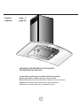 2
2
-
 3
3
-
 4
4
-
 5
5
-
 6
6
-
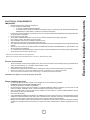 7
7
-
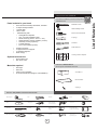 8
8
-
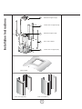 9
9
-
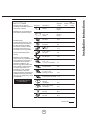 10
10
-
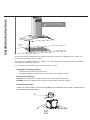 11
11
-
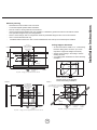 12
12
-
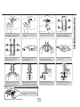 13
13
-
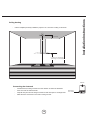 14
14
-
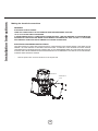 15
15
-
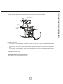 16
16
-
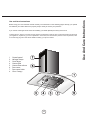 17
17
-
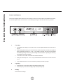 18
18
-
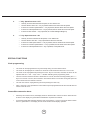 19
19
-
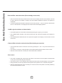 20
20
-
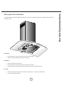 21
21
-
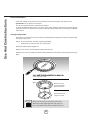 22
22
-
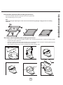 23
23
-
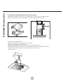 24
24
-
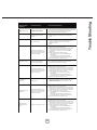 25
25
-
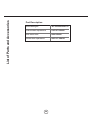 26
26
-
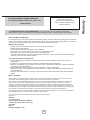 27
27
-
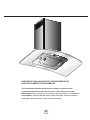 28
28
-
 29
29
-
 30
30
-
 31
31
-
 32
32
-
 33
33
-
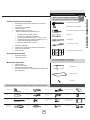 34
34
-
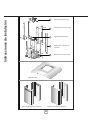 35
35
-
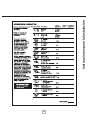 36
36
-
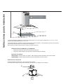 37
37
-
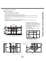 38
38
-
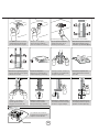 39
39
-
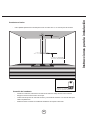 40
40
-
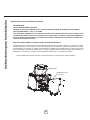 41
41
-
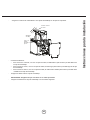 42
42
-
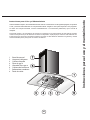 43
43
-
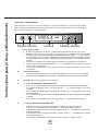 44
44
-
 45
45
-
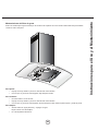 46
46
-
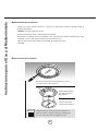 47
47
-
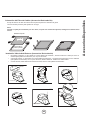 48
48
-
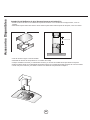 49
49
-
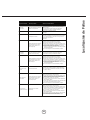 50
50
-
 51
51
-
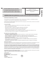 52
52


arietta DKI001MX36 Guía de instalación
- Categoría
- Campanas de cocina
- Tipo
- Guía de instalación
en otros idiomas
Artículos relacionados
-
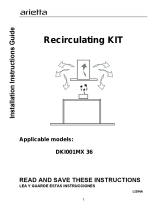 arietta KIT01938 Guía de instalación
-
 arietta Dekor Glass 30 Guía de instalación
-
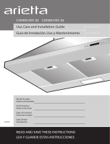 arietta CHN001MX36 Instrucciones de operación
-
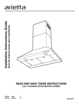 arietta ALS436SS Guía de instalación
-
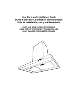 arietta DKW001MX36 Guía de instalación
-
 arietta PRO001MX30 Guía de instalación
-
arietta ADI436SSA Guía de instalación
-
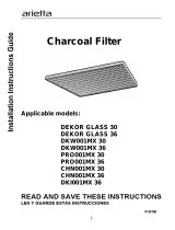 arietta KIT01658 Instrucciones de operación
-
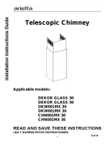 arietta KIT01935 Instrucciones de operación
-
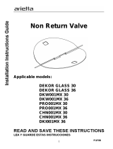 arietta KIT0102873 Guía de instalación


Otros documentos
-
ELICA ETB430S1 Install Instructions Toblino
-
GE Profile PV977NSS Manual de usuario
-
-
-
-
GE PV977NSS Guía del usuario
-
NOVA of California 3111588SN Guía de instalación
-
Electrolux RH36PC60GS Use and Care (Spanish)