RAM DSP_PowerPack ASYM Instrucciones de operación
- Tipo
- Instrucciones de operación

OPERATION MANUAL
BEDIENUNGSANLEITUNG
MANUAL DE USUARIO
P-8654969
QXPDQXDoc
5/18
© 2018 by C.E. Studio-2 s.l.
http://ramaudio.com
e-mail: [email protected]
DSP_PowerPack
™
• ASYM Series
AS 2K3
AS 1K5

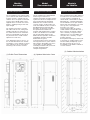
For the installation of the ASYM module
you need an internal chamber inside the
acoustic enclosure, separate from the
chamber where the speaker is mounted.
If preferred, the ASYM module can be
supplied with a rear metal case for this
purpose, avoiding having to make this
space airtight.
The module is fixed to the enclosure
with 8 M4 or M5 screws, sealing foam
should be placed in the joint between
the module and the box to avoid vibra-
tions (it is not advisable to put foam in
the joint between the module and the
optional rear metal case).
In the drawings below you can see: (1)
the external dimensions of the module
(front/profile), (2) the optional rear metal
case, and also (3) the recommended
machining of the acoustic enclosure.
Installation Requirements
Für die Installation des ASYM Moduls
wird ein eigenes Volumen im
Lautsprechergehäuse benötigt, welches
separat von dem des Lautsprechers ist.
Wenn gewünscht kann das ASYM
Modul mit einer metallenen Schale
versehen werden, um diesen Bereich
nicht extra luftdicht machen zu müssen.
Das Modul wird mit 8 M4 oder M5
Schrauben am Gehäuse befestigt, in
den Spalt zwischen Modul und
Gehäuse sollte Dichtschaum gegeben
werden, um Vibrationen zu vermeiden
(Es ist nicht ratsam zwischen dem
Modul und dem optionalen metallenen
rückwärtigen Gehäuse ebenfalls
Dichtschaum zu geben).
In den Zeichnungen weiter unten kann
man folgendes sehen: (1) Die äußeren
Abmessungen des Moduls (von Vorne,
von der Seite), (2) das optionale
rückwärtige Gehäuse und (3) auch die
benötigte Aussparung des
Lautsprechergehäuses.
Installationsvoraussetzungen
Module
Assembly
Para la instalación del modulo ASYM es
necesario tener una cámara interna en
el recinto acústico, separada de la
cámara donde está montado el altavoz.
Opcionalmente, el módulo ASYM pude
ser suministrado con un cajón metálico
trasero para este propósito, y así evitar
tener que hacer este alojamiento
hermético en el recinto.
La sujeción del módulo al recinto se
realiza mediante 8 tornillos M4 o M5, y
debe colocarse una junta de espuma
entre el módulo y la caja para evitar
vibraciones (no es recomendable poner
esta junta entre el modulo y el cajón
metálico opcional).
En los planos de debajo de estas líneas
se muestran: (1) las dimensiones exter-
nas del módulo (frontal/perfil), (2) las
del cajón opcional, así como (3) el
mecanizado recomendado a realizar en
el recinto acústico.
Requisitos de Instalación
Montaje
del Módulo
Modul
Zusammenbau
(3) Cabinet Mechanization
(2) Optional Aluminium Case(1) Profile-Front Dimensions

The connection of the speakers to the
module is done using two JST VHR-2N
connectors provided. A cable should be
crimped to the terminals (1.25mm
2
section maximum) and placed on the
connector box, so that the metallic tab
fits into place.
The connection is as follows:
Speakers Connection
Der Anschluss der Lautsprecher am
Modul erfolgt durch zwei JST VHR-2N
Stecker. Ein Kabel wird auf die
Anschlussstifte gecrimpt (maximal
1,25mm²) und ins Steckergehäuse
gesteckt, so dass der metallene Stift
einrastet.
Der Anschluss erfolgt wie folgt:
Lautsprecher Anschluss
Connection
and Description
La conexión de los altavoces al modulo
se realiza a través de 2 conectores JST
VHR-2N suministrados. Debe de crim-
parse un cable a los terminales
(sección máxima de 1.25mm
2
) e intro-
ducir los mismos sobre la caja del
conector, de forma que la pestaña
metálica se aloje en su hueco.
El conexionado es el siguiente:
Conexión de Altavoces
Conexión y
Descripción
Verbindung und
Beschreibung
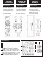
Signal Input: Female XLR Connector for signal input.
Signal Link: Male XLR Connector for signal link.
Ethernet Connectors: RJ45, two ports Ethernet switch.
USB Connector: B type USB connection.
LED ON:power supply ON. Blinking indicates StandBy mode.
LED SIGNAL: input signal presence indication.
LED LIMIT: lights when the DSP limiters are working.
LED CLIP: the maximum input or output has been reached.
Quick Preset: press the button for 3 seconds to change the
desired output preset.
ON: press SET1 button for 2s to turn on (in StandBy mode).
LEVEL: push SET 3-4 buttons simultaneously to enter LEVEL
mode (both LEDs light up). Then use 3 and 4 to change level.
Mains connection: inlet and outlet powerCON True1
connection. It works also as a main switch, as it is a connec-
tor with breaking capacity.
3
2
Front Panel Description
1
4
5
6
7
3
4
5
6
2
1
7
(Optional case suggested connection)

Technical Specifications Datos TécnicosTechnische Daten
©2018 by C.E. Studio-2 s.l. - Pol.Ind. La Figuera - C/Rosa Luxemburgo nº34 - 46970 Alaquas - Valencia - SPAIN
Phone:+34 96 127 30 54 Fax:+34 96 127 30 56 - http://ramaudio.com - e-mail: [email protected]
RAM Audio
®
, ICL™, PMS™ and PowerPack™ are registered trademarks of C.E. Studio-2 s.l. All other names are trademarks of their respective companies.
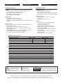
DSP Specifications
Output Power Configuration AS 2K3 AS 1K5
(Selectable by channel) CH-A CH-B CH-A CH-B
8 ohm 1500W 400W 400W 400W
4 ohm 1500W 750W 750W 750W
2 ohm 750W 750W 750W 750W
Bridge 8 ohm - 1500W
Bridge 4 ohm - 1500W
Total Harmonic Distortion <0.05% <0.05%
Efficiency >90% >90%
Damping Factor (20-500Hz @8Ω) >400 >400
Voltage Gain 26dB-38dB 26dB-38dB
Operational Mains voltage 85-265V AC/50-60Hz 85-265V AC/50-60Hz
Consum. @4Ω, 1/8 r.p., 230V AC 1.7 A 1.2 A
Power Factor >0.95 >0.95
Efficiency >90% >90%
Dimensions
External Plate WxH 130x443 mm 130x443 mm
Internal Enclosure WxHxD 100x423x55 mm 100x423x55 mm
Occupied Volume (optional case) 2 l 2 l
Weight 1.5 kg 1.5 kg
Connections: XLR Input, XLR Link, powerCON True1 in-out, USB, 2x RJ45, barrier strip (in optional case)
Protections: Turn-on transients, Over-heating, DC, RF, Short-circuit, mismatched loads, ICL™, PMS™
Overall:
• High performance 96kHz 120dB 32 bits AD/DA converters
• 64 bit double-precision 96kHz DSP process
• 0.6ms minimum process latency time
• Up to 3000 taps custom FIR process
• Up to 562ms total audio delay
Input Section:
• Gain, Mute and Phase inversion
• Input Delay: 0 to 140 meters (406ms)
• Input EQ: 31 GEQ + 8 PEQ (Parametric, Shelving, LP, HP, BP,
SB, AP)
Output Section:
• Crossover Filters: FIR and IIR (up to 48dB/oct, Butterworth /
Linkwitz-Riley / Bessel)
• Output Delay: 0 to 18 meters (52ms) per channel
• Output IIR EQ: 12 filters per channel (Parametric, Shelving,
LP, HP, BP, SB, AP)
• Output FIR EQ: 20 filters per channel (Parametric, Shelving,
LP, HP, BP, SB, AP), or Custom up to 3000 taps
• RMS, Peak, and Thermal limiter per channel
Amplifier Specifications
Control & Monitor:
• Standby mode for remote turn-on
• Real time impedance monitor
• Stby., Signal, Lim, Clip, Temp and Prot monitor
• Input, Output, Temperature and Current meters
Communications:
• Two ports Ethernet switch for daisy chain
connection
• USB 2.0, Type B connector
Overall:
• 20 Manufacturer preset memories library
• 5 User preset memories library
• 4 Quick Preset selection
• Manufacturer/Installer/User passwords
• Independent selectable output power per
channel (Z dependant)
• User control groups for virtual Equalization,
Gain and Delay
• Zone management for library, stand-by and
alerts information
• Smaart
®
analysis software integration
RAM_OCS Control
CAUTION
RISK OF ELECTRIC SHOCK
DO NOT OPEN
The exclamation point inside
an equilateral triangle indica-
tes the existence of internal
components whose substitu-
tion may affect safety.
The lightning and
arrowhead symbol
warns about the
presence of uninsulated
dangerous voltage.
To avoid fire or electrocution risk do not expose
the unit to rain or moisture. To avoid electric
shock, do not open the unit. No user serviciable
parts inside. In the case of disfunction, have the
unit checked by qualified agents. Class I device.
-
 1
1
-
 2
2
-
 3
3
-
 4
4


