GE PVW7301EJ1ES Guía de instalación
- Categoría
- Campanas de cocina
- Tipo
- Guía de instalación
Este manual también es adecuado para

I stallatio
I structios
GJassWalJ
Chimney Vent Hoods
PVW7301, PVW7361
Pl "If you have questions, call 800.GE.CARES (800.432.2737) or visit our website at: GEAppliances.com"
BEFORE YOU BEGIN
Read these instructions completely and
carefully.
.IMPORTANT - Savetheseinstructions
forlocalinspector'suse.
,IMPORTANT -Observeallgoverning
codes and ordinances.
, Note to Installer-Be sure to leavethese
instructionswiththe Consumer.
, Note to Consumer - Keep these instructions
forfuturereference.
, Skilllevel- Installationofthisvent hood
requiresbasicmechanical and electricalskills.
, Completion time - Approximately i to 3 hours
, Proper installationisthe responsibilityofthe
installer.
* Product failure due to improper installation is
not covered under the Warranty.
^,,-CAUTION: Due tothe weightand sizeof
thesevent hoods and to reduce the riskof
personalinjuryordamage to the product,TWO
PEOPLE ARE REQUIRED FOR PROPER
INSTALLATION.
FOR YOUR SAFETY:
AWARNING: Beforebeginningthe
installation, switch power off at service panel and
lock the service disconnecting means to prevent
power from being switched on accidentally.
When the service disconnecting means cannot
be locked, securely fasten a prominent warning
device, such as a tag, to the service panel.
kLW/'_I_I_i I I_i_: TO REDUCE THE RISK
OF FIRE, ELECTRIC SHOCK OR INJURY TO
PERSONS, OBSERVE THE FOLLOWING:
A. Installation work and electrical wiring
must be done by qualified person(s) in
accordance with all applicable codes and
standards, including fire-rated construction.
B. Sufficient air is needed for proper
combustion and exhausting of gases
through the flue (chimney) of fuel burning
equipment to prevent back drafting. Follow
the heating equipment manufacturer's
guidelines and safety standards such
as those published by the National Fire
Protection Association (NFPA), the
American Society for Heating, Refrigeration
and Air Conditioning Engineers (ASHRAE)
and the local code authorities.
C.
D.
E.
When cutting or drilling into wall or ceiling,
do not damage electrical wiring and other
hidden utilities.
Ducted fans must always be vented to the
outdoors.
Turn off breaker to adjacent rooms while
working.
A, ,,,^,-., ,,,, ,., ,,'-
_W/4LKi_ilI_i_: TO REDUCE THE RISK
OF FIRE, USE ONLY METAL DUCT WORK.
!
Z
r-
r-
!
O
Z
!
Z
-4
C
N
-4
!
O
Z
(991.0364.613revl)31-ii007 04-15 GE

Z
0
g
Z
0
i
_J
_J
Z
i
Installation Preparation
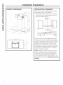
PRODUCT DIMENSIONS
4-15/16"
i0-i
15-3/4" _
© ©
18-1/2"
14i3/16" r
INSTALLATION CLEARANCES
These vent hoods are designed to be installed
onto a wall with no above cabinets.
, Install these hoods between the 24" required
minimum and 36" recommended maximum
above the cooking surface.
24" Required IVlin.
36" Recommended Max.
The vent hood must be installed between the
24" required minimum and 36" recommended
maximum above the cooking surface. The hood
installation height above the cooking surface
depends upon ceiling height and duct cover
limitations. The telescopic duct cover conceals
the ductwork running from the top of the hood
to the ceiling. For supplied duct cover ceiling
heights, see table on page 5.
NOTE: Installation height should be measured
from the cooking surface to the lowest part
of the hood. This hood must be installed onto
a wall. It can be vented to the outdoors, or it
can be installed for recirculating operation. For
recirculation operation, see Recirculation Install
Planning.
31 11007

Installation Preparation
ADVANCE PLANNING
Duct Install Planning
, This hood is designed to be vented vertically
through the ceiling. Use a 6" round duct. Use
locally supplied elbows to vent horizontally
through the rear wall.
, Use metal ductwork only.
, Determine the exact location of the vent hood.
, Plan the route for venting exhaust to the
outdoors. To maximize the ventilation
performance of the vent system:
1. Minimize the duct run length and number of
transitions and elbows.
2. Maintain a constant duct size.
3.Seal alljoints with duct tape to prevent any
leaks.
4. Do not use any type of flexible ducting.
, Install a wall cap or roof cap with damper
at the exterior opening. Purchase the wall or
roof cap and any transition and length of duct
needed in advance.
, When applicable, install any makeup
(replacement) air system in accordance
with local building code requirements. Visit
GEAppliances.com for available makeup air
solutions.
Recirculation Install Planning
A recirculation duct (included) and one charcoal
filter (not included) are necessary for recirculation
installation.
Power Supply Planning
The location of the power supply connection is
called out in the Prepare the Wall section on
page 6.
POWER SUPPLY
IMPORTANT- {Please read carefully}
AWARNING:
FOR PERSONAL SAFETY,THIS APPLIANCE MUST BE
PROPERLYGROUNDED.
Remove house fuse or open circuit breaker
before beginning installation.
Do not use an extension cord or adapter plug
with this appliance. Follow National Electrical
Codes or prevailing local codes and ordinances.
Electrical supply
These vent hoods must be supplied with 120V,
60Hz, and connected to an individual, properly
grounded branch circuit, and protected by a 15
or 20 amp circuit breaker or time delay fuse.
, Wiring must be 2 wire with ground.
, If the electrical supply does not meet the above
requirements, call a licensed electrician before
proceeding.
, Route house wiring as close to the installation
location as possible in the ceiling or wall.
, Connect the wiring to the house wiring in
accordance with local codes.
Grounding instructions
The grounding conductor must be connected to
a ground metal, permanent wiring system, or an
equipment-grounding terminal or lead on the hood.
AWARNING: The improper connection
of the equipment-grounding conductor can result
in a risk of electric shock. Check with a qualified
electrician or service representative if you are in
doubt whether the appliance is properly grounded.
!
Z
I'-
I--
!
O
Z
mo
m
-0
:1>
!
O
Z
31 11007 3

Z
O
g
Z
O
i
_J
_J
Z
i
Installation Preparation
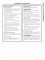
TOOLS AND MATERIALS REQUIRED
(NOT SUPPLIED)
Pencil and tape measure
Safety glasses
Phillips screwdriver
Level
Electric drill with #2 Phillips,
flat head, and 9/32" drill bit
Wire cutter/stripper
Aluminized
Duct tape
UL listed wire nuts
©
Strain relief for
junction box
REMOVE THE PACKAGING
A CAUTION: Wear gloves to protect
against sharp edges.
, Remove the duct covers.
. Remove the hardware bag, literature package
and other boxed parts.
. Remove and properly discard the protective
plastic wrapping and other packaging materials.
PLAN THE INSTALLATION
A CAUTION: To reduce risk of fire and to
properly exhaust air, be sure to duct the air
outside - Do not vent exhaust air into spaces
within walls or ceilings or into attics, crawl spaces,
or garages.
PARTS SUPPLIED FOR INSTALLATION
.1 Hardware Package
,1 Literature Package
PARTS NEEDED FOR INSTALLATION
, i Strain Relief
, Power Supply Cable
, i Wall or Roof Cap (for ducted venting only)
, All Metal Ductwork (for ducted venting only)
, Recirculation Duct (for recirculation install only)
WARNING:
PERSONAL INJURY HAZARD
Because of the weight and size of the rangehood
canopy. It is recommended that 2 people are used
to install the range hood. Failure to properly lift
rangehood could result in damage to the product
or personal injury.
NOTE: This rangehood can be installed as either
ducted or recirculation. In a ducted application,
this rangehood can be vented through the wall
or ceiling. When installed for recirculation, the
rangehood vents out the sides of the duct cover.
NOTE: Before making any cuts or holes for
installation, determine which venting method will
be used and carefully calculate all measurements.
- 31 11007

Installation Preparation
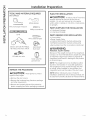
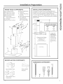
RANGE HOOD COMPONENTS
A. Canopy Section H. Mounting Bracket
B. Upper Duct Cover I. Washers
C. Lower Duct Cover J, Canopy Mounting
D. Mounting Screws Anchors
E. Duct Cover K. Duct Cover Anchors
Mounting Brackets L. Dry Wall Self-
F, Damper Tapping Screws
G, Duct Cover Screws (for Junction Box)
D
G
C
A
G
D
RECIRCULATION COMPONENTS
Recirculation Duct
Recirculation Duct
Extensions
Recirculation
Bracket
INSTALLATION DIMENSIONS
The Glass Chimney Hoods are adjustable and
designed to meet varying ceiling heights. The duct
covers can be adjusted for ceilings between
7' 4-1/4" and 9' 3-1/4" depending on the distance
between the bottom of the hood and the cooktop
(distance X).
T
5-1/8" min
16-1/8" max
21-i
1-3/4';
36"
V
Upper
Duct Cover
8"
Lower
Duct Cover
_ 18-1/2" _
X = Distance From Hood To Cooktop
(Varies depending on installation}
Required Min 24",
Recommended Max - 36"
also consult cooktop
manufacturer's recommendation
Cabinet Base
I
Required Min & Recommended
Max Ceiling Height Examples
x = 24" x = 36"
Min Min
7' 4-1/4" 8' 4-1/4"
Mox Max
8' 3-i/4" 9' 3-i/4"
For higher ceiling
installations, the
High Ceiling Duct
Cover Kit {JXDC71}
includes o new
29-1/8" lower duct
cover which would
replace the 21-3/8"
lower duct cover
that come with the
hood
HARDWARE COMPONENTS
D
%
G
<
<
<
<
1
J K L
!
Z
¢/)
r"
r-
!
O
Z
"D
rrl
"0
!
O
Z
31 11007 S

Z
O
g
Z
O
i
_J
_J
Z
i
Installation Preparation
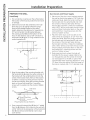
PREPARE THE WALL
Hood Body
.
.
Put a protective covering over the surface below
the locution of the hood to protect from dirt and/
or damage.
Determine and mark the centerline on the wall
(draw line up to the ceiling) where the range
hood will be installed. Bused on the ceiling
height, determine the distance 24" required min,
36" recommended max (×)needed between
the cooking surface (B)and the bottom of the
hood. To this distance, add 12-5/8" and draw a
horizontal line (A)about 24" long centered on the
vertical centerline (C).
112-5/8"
. @
I
L -- --T-- -- _" --'-- -- J
D'/- I !"
1124 to 36"
.
Align the top edge of the mounting bracket with
the horizontal line (A).Align the center notches of
the bracket with the centerline (C)and murk the
center of the bracket holes. Remove the bracket
to drill the 2 canopy mounting anchors into the
wall at the markings. Place the mounting bracket
buck on the wall and install the 2 mounting
screws with 2 washers into the anchors. Tighten
screws.
,_¢r_)Hood Mounting _,
Mounting Screws & Washers
4. Draw a second horizontal line (D)that is 1" added
from the (×) distance. Drill a hole into the wall with
a 9/32" drill bit at the intersection of the horizontal
line (D)and vertical centerline (C).Insert a duct
cover anchor.
Duct Covers and Power Supply
1. Place one of the duct cover brackets against
the wall so that its top edge is 1/16" from the
ceiling and level. Align the center notches of
the bracket and the centerline (C)and mark
the centers of the bracket holes. Remove
the bracket to drill the 2 holes for installation
with a 9/32" drill bit, and insert the duct cover
anchors. Place the bracket back on the wall
and install the 2 mounting screws into the
anchors. Tighten screws.
2. Place the other duct cover bracket on the
wall so that its top edge is 15-1/2" from the
ceiling and level. Align the center notches of
the bracket and the centerline (C)and mark
the centers of the bracket holes. Remove
the bracket to drill the 2 holes for installation
with a 9/32" drill bit, and insert the duct cover
anchors. Place the bracket back on the wall
and install the 2 mounting screws into the
anchors. Tighten screws.
3. Determine and mark where the hole will
be drilled for the power supply cable to be
run through the wall. The center of the hole
can be located 4" to the left or right of the
centerline (C)while remaining between 4" and
13" down from the ceiling. Once the center of
the hole is marked, drill a 1 1A"diameter hole.
Ceiling
fr°.m 14" 4" !/!6"
CedmgZi-.,_€-----_-
/
.......i...............
I
I
L I "J
I
15 1/2"

Installation Instructions
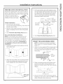
PREPARE HOOD FOR INSTALLATION
Remove the greose filter from the unit and set
oside. The greose filter is removed by pressing
the handle in front of the filter. When replacing,
make sure that the filter is
properly positioned with the
handles in front and visible.
Vented Installations
1. Securely press the damper
on top of the exhaust opening. Check that the
damper opens freely.
2. Remove and properly discord the protective
plastic wrapping from the hood and grease
filter.
3. Go to Mount the Glass Range Hood section.
Non-vented {ductless)Installations
NOTE: A recirculetion duct, extensions, and
bracket ere all included with the hood end
ere necessary for recirculetion installation. A
charcoal filter, not included, is also needed
for recirculation installation. The damper is
not installed on the unit with recirculation
installation.
1. Install the recirculetion duct extensions to the
recirculetion duct.
2, Attach the recirculution duct mounting bracket
to the recirculution duct using the duct cover
screw supplied with the hardware package,
Attach Using
Duct Cover
Screw
. Fit the recirculotion duct with extensions over
the vent exhaust outlet and push down to seat
on outlet. Attach the vertical duct work to the
top of the hood. Check that the recirculution
duct is in the proper orientation (hole facing
towards the buck of the hood).
J
Recirculation
Duct with -Vent Exhaust
Extensions Outlet
NOTE:
Hole must
be facing
toward back
of hood.
4. Go to Mount the Glass Range Hood section.
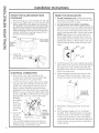
MOUNT THE GLASS RANGE HOOD
.
NOTE: If ductless (recirculation)installation,
follow steps 1-6. If ducted installation, follow
steps 1-3.
Using 2 or more people, lift the range hood and
place on the hood mounting bracket. Make
sure the bracket fully engages the holes on the
hood body.
Duct Cover
;_'_ Screw
I
.
Place a mounting screw into the duct cover
anchor at the center slot provided on the
bottom of the back side of the hood. Securely
tighten.
.
Mounting Screw
Secure the hood to the mounting bracket by
fastening a duct cover screw in hole (B) on both
sides of bracket shown previously
!
Z
¢/9
I--
I--
!
O
Z
!
Z
¢/9
--I
C
--t
!
O
Z
31 11007 7

Z
O
i
I--
U
l--
Z
u
Z
O
g
_J
_J
Z
i
Installation Instructions
MOUNT THE GLASS RANGE HOOD
(Continued)
5.
Remove the top duct cover bracket from the wall.
Align the top edge of the duct cover bracket with
the top edge of the recirculation duct mounting
bracket that is attached to the recirculation duct.
Align the center notches of each bracket. Place
both brackets back onto the wall in the previous
position. Install the 2 mounting screws into the
anchors and securely tighten.
Ceiling
Top Duct
Cover
Bracket
Duct Bracket
. Attach the
CHARCOAL FILTER;
(not included).
ELECTRICAL CONNECTION
.
.
Remove the cover from the field wiring
compartment. Feed the Power Supply Cable
through the hole in the compartment.
Connect the Power Supply Cable to the range
hood junction box through the hole that was
drilled in the "Preparing the Wall" section on
page 6. Attach the White lead of the power
supply (A) to the White lead of the range hood
(D) with a wire nut. Attach the Black lead of the
power supply (B)to the Black lead of the range
hood (C)with a wire nut. Connect the Green
(E)(Green
and Yellow)
ground
wire under
the Green
grounding
screw.
Secure the
junction
B
E ,D
I= Secure
junction
3. X box to the
wall using
box to the these
holes.
wall using ............
2 dry wall self-tapping screws into the two
diagonal holes in the junction box. Reattach
the field wiring compartment cover.
FINISH THE INSTALLATION
i.
.
Ducted installation only: Connect the house
ducting to the damper on the hood body. Seal
all connections with duct tape.
For ducted and recirculation installation:
Install the upper duct cover. Slightly spread the
sides of the cover apart and hook them behind
the duct cover mounting brackets. Attach the
cover to the brackets with 4 duct cover screws.
NOTE: Depending on the ceiling height and
hood install height, the upper duct cover can
be installed with the exhaust vents on the top
towards the ceiling, or flip the duct cover and
hide the exhaust vents under the lower duct
cover.
3. Install the lower duct cover. Slightly spread the
sides of the cover apart and hook them behind
the upper duct cover and the wall. Slide the
lower duct cover down to fit securely into the
top of the range hood.
4. Finish attaching the lower duct cover to the
chimney of the vent hood with 2 duct cover
screws into holes on both sides of the cover.
A screw hole
is located on
each side of
the duct cover.
S.
.
Reinstall the metal grease filter to the vent
hood.
Turn the power supply on. Turn on blower
and light. If the rangehood does not operate,
check that the circuit breaker is not tripped
or the house fuse blown. If the unit still does
not operate, disconnect the power supply and
check that the wiring connections have been
made properly.
31 11007

I struccio es
de i stal ci6n
Pared de Vidrio
Campanas de Ventilaci6n de ia Chimenea
PVW7301, PVW7361
=
r_ zPreguntms? Llome ol 800.GE.CARES (800.432.2737) o visite nuestro sitio Web en: GEApplionces.com
ANTES DE COMENZAR
Lea estas instrucciones por completo y con
detenimiento.
.IMPORTANTE - Guordeestos
instrucciones para el uso de inspectores
locales.
.IMPORTANTE - cumplocontodoslos
c6digos y ordenanzas vigentes.
, Nota al instalador - AsegOrese de dejar estas
instrucciones con el Consumidor.
, Nota al consumidor - Conserve estas
instrucciones pare referencia futura.
, Nivel de capacidad - La instalaci6n de esta
campana de ventilaci6n requiere capacidades
mecanicas y el6ctricas basicas.
, Tiempo de finalizad6n - Aproximadamente
de 1 a 3 horas.
,,El instalador tiene la responsabilidad de
efectuar una instalaci6n adecuada.
, La Garantia no cubre las fallas del producto
debido a una instalaci6n incorrecta.
A
I" K I:::L, _ U L, IUI_I" Debido al peso
y tama_o de estas campanas de ventilaci6n y
para reducir el riesgo de lesiones personales o
da_os al producto, SE NECESITAN DOS
PERSONAS PARA REALIZAR UNA INSTALACI6N
CORRECTA.
PARA SU SEGURIDAD:
A Af-_l ir-_-r-r-L ,_mA
it,/"_UVCK|EI_IL, I_: Antes de comenzar
la instalaci6n, desconecte la energia del panel de
servicio y bloquee los medios de desconexi6n
para evitar el accionamiento de la energia de
manera accidental. Cuando los medios de
desconexi6n de servicio no pueden bloquearse,
coloque sobre el panel de servicio un dispositivo
de advertencia bien visible, como una etiqueta.
A^r,, irr,-rr_,r,^
Ji/,_uvr_.r_/r_l_bl/..,_: PARA REDUCIR EL
RIESGO DE INCENDIO, DESCARGA ELECTRICA
O LESIONES A PERSONAS, CUMPLA CON LOS
SIGUJENTES PUNTOS:
A. El trabajo de instalaci6n y el cableado
electrico deben set realizados pot una
persona(s) calificada de acuerdo con todos los
c6digos y estandares aplicables, incluyendo
construcciones resistentes al fuego.
B. Es necesario contar con suficiente
cantidad de aire para una combusti6n
y salida de gases adecuadas a traves
del conducto (chimenea) del equipo de
consumo de combustible, a fin de evitar
rafagas de aire. Siga las pautas del
fabricante del equipo de calefacci6n y
los estandares de seguridad, tales como
aquellos publicados por la Asociaci6n
Nacional de Protecci6n contra Incendios
(National Fire Protection Association,
NFPA), la Sociedad Estadounidense
para la Calefacci6n (American Society for
Heating), los Ingenieros de Refrigeraci6n y
Acondicionadores de Aire (Refrigeration and
Air Conditioning Engineers, ASHRAE y las
autoridades de los c6digos locales.
C. AI cortar o perforar una pared o un
cielorraso, no daBe el cableado electrico y
de otros servicios ocultos.
U.
E.
Los ventiladores con conducto siempre
deben contar con ventilaci6n hacia el exterior.
Desconecte el disyuntor de habitaciones
adyacentes mientras este trabajando.
A ^,-,1 ,,--,-,,-,-,-,,,,-,,^
,m_h_UVi::R/i::|_i!,.,i/'_: A FIN DE
REDUCIR EL RIESGO DE INCENDIOS, USE
SOLO CONDUCTOS DE METAL.
!
Z
(.t)
:x)
C
N
O
Z
m
(.t)
C)
rrl
!
Z
(.t)
_>
r'-
_>
d_
!
O,
Z
(991.0364.613 revl) 3!-11007 04-15 GE

Z
"O
i
U
<_
_u
<_
Z
i
<_
_u
<_
<_
Z
"O
i
U
<_
<_
Preparaci6n para la instalaci6n
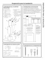
DIMENSIONES DEL PRODUCTO
15-3/4" _
0 0
18-1/2"
14i3/16" r
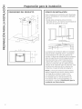
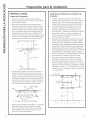
ESPACIO DE INSTALACI6N
Estascampanas de ventilaci6n est6n disefladas
para ser instaladas en una pared sin gabinetes
superiores.
. Instale estas campanas entre el minimo
requerido de 24"y el m6ximo recomendado de
36" sobre la superficie de cocci6n.
I
24" Required IVlin.
36" Recommended Max.
1
La campana de ventilaci6n debe set instalada
entre el minimo requerido de 24" y el m6ximo
recomendado de 36" sobre la superficie de
cocci6n. La altura de instalaci6n de la campana
sobre la superficie de cocci6n depende de la
altura del cielorraso y las limitaciones de la
cubierta del conducto. La cubierta plegable
oculta los conductos que van desde la parte
superior de la campana hasta el cielorraso. Para
las alturas de cielorraso de las cubiertas de
conductos, consulte la tabla de la p6gina 5.
NOTA: La altura de instalaci6n debe medirse
desde la superficie de cocci6n hasta la parte
m6s baja de la campana. Puede contar
con ventilaci6n hacia el exterior, o puede
set instalada para un funcionamiento con
recirculaci6n. Para un funcionamiento con
recirculaci6n, consulte la Planificaci6n para la
lnstalaci6n con Recirculaci6n.
31 11007

Preparaci6n para la instalaci6n
PLANIFICACI6N PREVIA
Planificaci6n para la Instalaci6n con Conducto
, Esta campana est6 diseBada para ventilarse
en forma vertical a trav6s del cielorraso.
Use un conducto circular de 6". Utilice codos
suministrados en forma local para ventilaci6n
horizontal a trav6s de la pared trasera.
, Determine la ubicaci6n exacta de la campana
de ventilaci6n.
, Planifique el recorrido de la salida de ventilaci6n
hacia el exterior. A fin de maximizar el
rendimiento de la ventilaci6n del sistema de
ventilaci6n:
1. IVlinimice la Iongitud del conducto y el nOmero
de transiciones y codos.
2. IVlantenga un tamaBo de conducto constante.
3.Selle todas lasjuntas con cinta para
conductos a fin de evitar p@didas.
4. No utilice conductos flexibles de ning0n tipo.
. Instale una cubierta de pared o casquete
de techo con un regulador de tiro en la
abertura exterior. Solicite pot adelantado la
cubierta de pared o el casquete de techo y
cualquier transici6n o Iongitud de conducto
necesarios.
, Cuando corresponda, instale un sistema de
reposici6n (reemplazo) de aire de acuerdo con
los requisitos del c6digo local de construcci6n.
Para acceder a soluciones de aire disponibles,
visite GEAppliances.com.
Planificaci6n de Instalaci6n con Recirculaci6n
Un conducto de recirculaci6n (incluido) y un filtro
de carb6n (no incluido) son necesarios para la
instalaci6n con recirculaci6n.
Planificaci6n del Suministro de Corriente
La ubicaci6n de la conexi6n del suministro
de corriente es indicada en la secci6n de
Preparaci6n de la Pared en la p6gina 6.
SUMINISTRO DE ENERGIA
IMPORTANTE - (Tenga a bien leer cuidadosamente)
AADVERTENCIA:
PARASEGURIDAD PERSONAL, ESTEAPARATO
DEBECONECTARSE A TIERRA DE IVlANERA
ADECUADA.
Quite el fusible o abra el interruptor de circuitos
antes de comenzar la instalaci6n.
No utilice un cable de extensi6n o un enchufe
adaptador con este artefacto. Siga los C6digos
EI6ctricos Nacionales o c6digos y ordenanzas
locales vigentes.
Suministro el_ctrico
Estas campanas de ventilaci6n deben contar
con un suministro de 120V, 60Hz, deben estar
conectadas a un circuito derivado individual con
una adecuada conexi6n a tierra y deben contar
con la protecci6n de un interruptor de circuitos
o un fusible con retraso de 15 o 20 amperios.
. El cableado debe ser de 2 hilos con conexi6n
a tierra.
• Si el suministro el6ctrico no cumple con los
requisitos anteriores, Ilame a un electricista con
licencia antes de continuar.
Dirija el cableado dom6stico Io m6s cerca
posible a la ubicaci6n de la instalaci6n, en el
cielorraso o pared trasera. Ver p6gina 14 para
m6s detalles.
. Conecte el cableado al cableado dom6stico
en cumplimiento con los c6digos locales.
Instrucdones de conexi6n a tierra
El conductor a tierra debe conectarse a un metal
con conexi6n a tierra, un sistema de cableado
permanente o una terminal o conductor de
conexi6n a tierra del equipamiento en la
campana.
A ADVERTENCIA: Unaconexi6n
inadecuada del conductor de conexi6n a tierra
del equipamiento puede provocar un riesgo
de descarga el6ctrica. Consulte a un electricista
calificado o representante de servicio t6cnico
si tiene dudas sobre la correcta conexi6n a tierra
del artefacto.
"0
m
"0
!
O,
Z
"0
!
Z
--t
!
O,
Z
31 11007 3

Z
"O
i
_J
I--
Z
i
_u
<_
Z
"O
i
l.LI
Preparaci6n para la instalaci6n
HERRAMIENTAS Y MATERIALES
REQUERIDOS (NO SUMINISTRADOS)
L6piz y cinta m6trica
Nivel
Gafas de seguridad
Destornillador
de estrella
Broca el6ctrica con Phillips
N° 2 de cabeza plana y
broca de 9/32"
Alicate pelacables
Cinta
aislante de
aluminio
_]_
Tapones de alambre
aprobados por UL
©
Alivio de tensi6n
para la caja de
conexiones
QUITE EL ENVOLTORIO
J
A PRECAUCION: seguantespara
protegerse de los bordes afilados.
, Quite las cubiertas de los conductos.
, Quite la bolsa de piezas, el paquete
de instrucciones y otras piezas en cajas.
, Quite y descarte adecuadamente el envoltorio
pldstico de protecci6n y otros materiales
de empaque.
PLAN DE INSTALACI6N
J
APRECAUCION: A finde reducir
riesgos de incendios y para que el aire salga de
forma apropiada, aseg_rese de que el aire sea
conducido hacia fuera - No ventile el aire de la
salida hacia espacios dentro de paredes o
cielorrasos o 6ticos, espacios muy bajos o garajes.
PIEZAS PROVISTAS PARA LA
INSTALACI6N
, i Paquete de Herramientas
,, 2 Paquete Escrito
PIEZASNECESARIASPARA LA
INSTALACI6N
,1 Amortiguador de Refuerzo
, Cable de Suministro de Corriente
, Una Tapa de Pared o Techo (para ventilaci6n
con conducto Onicamente)
, Toda la Tuberfa Pletdlica (para ventilaci6n con
conducto Onicamente)
, Conducto de Recirculaci6n (para instalaci6n con
recirculaci6n t]nicamente)
ADVERTENCIA:
! RIESGO DE LESIONES PERSONALES
Debido al peso y tama_o de la base de la
campana extractora. Esrecomendable que
la campana extractora sea instalada por 2
personas. Si la campana no es elevada de forma
correcta, se podr6n producir da_os sobre el
producto o lesiones personales.
NOTA:Estacampana puede ser instalada con
conducto o con recirculaci6n. Enuna aplicaci6n
con conducto, esta campana puede set ventilada a
trav@sde la pared o del cielorraso. AIset instalada
pot recirculaci6n, la campana ventila hacia afuera
los costados de la cubierta del conducto.
NOTA: Antes de realizar cualquier corte o agujero
para la instalaci6n, determine qu6 m6todo de
ventilaci6n ser6 usado y con cuidado calcule
todas las medidas.
- 31 11007

Preparaci6n para la instalaci6n
COMPONENTES DE LA CAMPANA
E×TRACTORA
A. Secci6n de la Base H. Soporte de Montoje
B. Cubierta del Conducto I. Arondelus
Superior J. Soportes de Montoje de
C. Cubierto del Conducto la Base de la Campana
Inferior K. Soportes de la Cubierta
D. Tornillos de Nontaje del Conducto
E. Soportes de Montaje de L. Tornillos Autorroscantes
la Cubierta del Conducto para Pared Seca (Para la
F. Regulador Caja de Empalmes)
G. Tornillos de la Cubierta
del Conducto
D
G
C
G j
A
D
COMPONENTES DE RECIRCULACI6N
Conducto de Recirculaci6n
Soporte de
Recirculaci6n
Extensiones del Conducto de Recirculaci6n
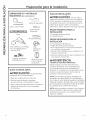
DIMENSIONES DE INSTALACI6N
LasCampanas con Chimenea de Vidrio son
ajustables y estan dise_adas para adaptarse a
diferentes alturas de cielorraso. Lascubiertas de los
conductos pueden serajustadas para cielorrasos
de entre 7' 4 _1./4"y9' 3 1/4",dependiendo de la
distancia entre la parte inferior de la campana y la
superficie de cocci6n (distancia ×).
T
Nin de 5 1/8"
M6x de 16 1/8"
V
T
21-3/8"
1-5/4';
]B"
V
Cubierta del __
Conducto Superior
Ejemplosde Altura Minima Requeriday
Altura M6xima Recomendadade Cielorraso
x = 24" x = 36"
Min. Min
7' 4-1/4" 8' 4-1/4"
M6x. M6x.
8' 3-1/4" 9' 3-1/4"
Cubierta del
Conducto Inferior
I
Oosel i
' _ 18-1/2" _
X = Distancia Desde la Campana
Hasta la Superficie de Cocci6n
(Varfa dependiendo de la instalaci6n}
Minimo Requeddo 24",
Iq6ximo Requerido - 36";
tambiBn consulte Io recomendadBn
del fabricante de cocinas
Base del Gabinete
Para realizar
instalaciones en
cielorrasos mBs altos,
el Kit de Cubiertas
de Conductos para
Cielorrasos Altos
(JXDC71) incluye uno
nuew cubierta de
conductos para 6reas
infedores de 29 1/8"
que reemplaza la
cubierta de conductos
paro 6reas inferiores
de 21 3/8" incluida
con la campana.
COMPONENTES DE LAS HERRAMIENTAS
D G
C
(
(
(
1
J K L
"0
m
"0
!
O,
Z
"0
im
!
Z
--t
im
!
O,
Z

Z
"O
i
U
_J
I--
Z
i
_J
tZ.
Z
"O
i
tZ.
Preparaci6n para la instalaci6n
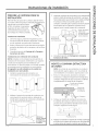
PREPARE LA PARED
Cuerpo de la Campana
1. Coloque una cubierta protectora sobre la superficie
debajo de la ubicaci6n de la campana, a fin de proteger
de la suciedad y/o daflos.
2. Determine y marque la linea central sobre la pared
(dibuje la linea hacia arriba hasta el cielorraso) donde la
campana extractora ser6 instalada. Enbase a la altura
del cielorraso, determine la distancia minima requerida
de 24" y la distancia m6xima recomendada de ]6" (×),
necesarias entre la superficie de cocci6n (B)y la parte
inferior de la campana. A esta distancia, agregue 12 5/8"
y dibuje una linea horizontal (A)de aproximadamente 24"
de Iongitud centrada sobre la linea central vertical (C).
A / ......... _
I
/I
I !2-5/8"
I [
,.. '_ ___ _ _v_ _.,
Di-- I
c_ !"
j24 to 36"
B_
i L
Alinee el extremo superior del soporte de montaje con
la linea horizontal (A).Alinee las ranuras centrales del
soporte con la linea central (C)y marque el centro de los
agujeros del soporte. Retire el soporte para perforar los
2 sostenes de montaje de la base en la pared, donde se
encuentran las marcas. Vuelva a colocar el soporte de
montaje en la pared e instale los 2tornillos de montaje
con 2 arandelas en los sostenes. Ajuste los tornillos.
A ,_ _._L-_'-_ _ e
Aqui
_;Soporte dd Hontaje <c_
Tornillos y Arandelas de Montaje
Dibujeuna segundaIfneahorizontal(D)con1"agregada
desdela distanciaX.Dibujeun agujeroen la pared
conuna brocade 9/S2"enlaintersecci6nde la Ifnea
horizontal(D)y la Ifneacentralvertical(C).Inserteun
sost6nen la cubiertadelconducto.
Cubiertas de Conductos y Surninistro de
Corriente
1. Coloque uno de lossoportes de la cubierta del
conducto contra la pared, de modo que su extremo
superior est6 a 1/16" del cielorraso y que quede
nivelado. Alinee las ranuras centrales del soporte
con la I[nea central (C)y marque los centros de
los agujeros del soporte. Retire el soporte para
perforar 2 agujeros para la instalaci6n con una
broca de 9/32%einserte los sostenes de la cubierta
del conducto. Vuelva a colocar el soporte en la
pared e instale los 2 tornillos de montaje en los
sostenes, Ajuste lostornillos.
2. Coloque el otro soporte de la cubierta del conducto
contra la pared, de modo que su extremo superior
est@a 15 1/2" del cielorraso y que quede nivelado.
Alinee lasranuras centrales del soporte con la linea
central (C)y marque los centros de los agujeros del
soporte. Retire el soporte para perforar 2 agujeros
para la instalaci6n con una broca de 9/32%e inserte
los sostenes de la cubierta del conducto. Vuelva a
colocar el soporte en la pared e instale los 2 tornillos
de montaje en los sostenes.Ajuste lostornillos.
3. Determine y marque el lugar donde el agujero
serc_perforado para que el cable de suministro
de corriente pueda pasar a trav6s de la pared. El
centro del agujero puede ser ubicado a a" hacia la
izquierda o derecha de la linea central (C),mientras
permanece a entre 4" y !]" del cielorraso. Una vez
marcado el centro del agujero, haga un agujero de
! 1X"de dic_metro.
Cielorraso
rT÷ I -mI--
aaiS"del [ a" 4" I
Cielorraso _.___2_
I
l
I
I
_ _ -_ .... -__
/
I
t
!/!6"
I
t
!5 !/2"
Sl 11007

Instruccionesde instalaci6n
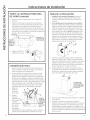
PREPARE LA CAMPANA PARA SU
INSTALACION
Retire el filtro de grasa de la unidad y deje el mismo
a un lado. Elfiltro de grasa es retirado presionando la
manUa que se encuentra frente
al filtro. AI realizar el reemplazo,
aseg6rese de que el filtro est6
correctamente posicionado con
las manijas en el frente y visibles.
InstaJaciones VentiJadas
1.
.
3.
Deforma segura, presione el regulador que se
encuentra sabre la abertura del escape. Controle
que el regulador se pueda abrir libremente.
Retire y descarte de forma adecuada el envoltorio
protector de pl6stico de la campana y de losfiltros
de grasa.
Consulte la secci6n de Montaje de la Campana
E×tractora de Vidrio.
Instalaciones sin ventilaci6n {sinconducto)
NOTA: Incluidos con la campana se encuentran un
conducto de recirculaci6n, extensiones y un soporte,
y todos son necesarios para la instalaci6n con
recirculaci6n. Unfiltro de carb6n, no incluido, tambi6n
es necesario para lu instalaci6n con recirculaci6n.
El regulador no est6 instalado en la unidad con
instalaci6n con recirculaci6n.
1. Instale las extensiones del conducto con
recirculaci6n al conducto con recirculaci6n.
.
Adhiera el soporte de montaje de conductos con
recirculaci6n al conducto mismo, utilizando el
tornillo para cubiertas de conductos suministrado
con el paquete de herramientas.
Adhiera el
mismo Usando
el Tornitlo de
la Cubierta det
Conducto
,
J
Conductode
Recirculuci6n
con Extensiones
Inserte el conducto de recirculaci6n con extensiones
sabre la sulidu del escape de ventiluci6n y empuje
huciu ubujo puru que coincidu con lu sdlidu. Adhieru
el conducto vertical u lu purte superior de Id
cumpunu. Controle que el conducto de recirculuci6n
se encuentre en Io orientuci6n correctu (con el
ugujero huciu Io purte truseru de Io cumpunu).
NOTA:Elagujero
debeestor
enfrentadohacia
la partetrasera
de lacampana.
Salida del Escape de
la Ventilaci6n
4. Consulte la secci6n de Montaje de la Campana
Extractora de Vidrio.
MONTE LA CAMPANA EXTRACTORA
DE VIDRIO
NOTA: Si setrata de una instalaci6n sin conducto
(recirculaci6n), siga los pasos 1 a 6. Sise trata de
una instalaci6n con conducto, siga los pasos 1 a 3.
1. Entre 2 o m6s personas, levanten la campana
extractora y coloquen el soporte de montaje de la
campana. Aseg6rese de que el soporte se adhiera
completamente al cuerpo de la campana.
Tornillode la Cubierta
_ "_I"_ del Conducto
i
Soportede
Montajede
laCampana
Campana
2. Coloque un tornillo de montaje en el sost6n de
la cubierta del conducto, sobre la ranura central
provista en la parte inferior del lado trasero de la
campana. Ajuste de forma segura.
/
/
Mounting Screw
3, Asegure la campana al soporte de montaje, ajustando
el tornillo de la cubierta del conducto en el agujero (B)
a ambos lados del soporte mostrado previamente.
!
Z
--I
C
N
!
O
Z
m
O
m
!
Z
--!
!
O,
Z

Z
"O
i
_J
l--
Of)
Z
i
IJJ
a
z
O
i
£3
::3
l--
Of)
Z
i
Instruccionesde instalaci6n
MONTE LA CAMPANA EXTRACTORA
DE VIDRIO (contin6a)
Retirede la pared etsoporte superior de la cubierta det
conducto.
Alinee etextremo superior del soporte de la cubierta det
conducto con etextremo superior det soporte de montaje
det conducto de recirculaci6n, etcual est6 adherido al
conducto de recirculaci6n. Alinee las ranuras centrales de
cada soporte. Vuetva a colocar ambos soportes en la pared,
en la posici6n previa. Instale los 2 tornitlos de montaje en los
sostenes y ajuste de forma segura.
Cielorraso
Soporte
de la Cu-I
bierta det
Conducto
Superior
porte del
Conducto de
Recirculaci6n
Adhiera el FILTRODE
CARBON(no incluido)
CONEXION ELECTRICA
1. Retire la cubierta del compartimiento del cableado de
campo. Alimente el Cable de Suministro de Corriente a
trav_s del agujero del compartimiento.
2. Conecte el Cable de Suministro de Corriente o la caja
de empalmes de la campana extractora, a troves del
agujero que fue realizado en la secci6n de "Preparaci6n
de la Pared" en la pagina 6.Adhiera el cable blanco del
suministro de corriente (A)al cable blanco de la campana
extractora (D)con una tuerca para cable. Adhiera el cable
negro del suministro de corriente (B)al cable negro de
la campana extractora (O con una tuerca para cable.
Conecte el cable a tierra verde (E)(verde y amarillo)
debajo del C__ _-_ B
tornillo de
E D
conexi6na f! -__.,_
tierra verde, i ........
5. Asegure i : A
,acajo o
empalmes a la /j Asegure
paredusando E I ° _'_-_'_--"iJ# _ tacajade
\! _ _ _------_J_ i\ empalmes
2tornillos "i_ . _,_ i _I \alapared
autorroscantes t_F/ _ _usanao
para pared !_< J_ _-_ k / ?stos agu-
seca en los I_ T_r, -- -- x__/ jeros.
dos agujeros
diagonales de la cuja de empalmes. Vuelva a odherir la
cubierta del compartimiento de cableado de campo.
FINALICE LA INSTALACI6N
1. Instalaci6n con conducto 6nicamente: Conecte el
conducto hogarefio al regulador del cuerpo de la
campana. Selle todas las conexiones con cinta para
conducto.
2. Para instalaciones de recirculaci6n y con conducto:
Instale la cubierta del conducto superior. Lentamente
separe los costados de la cubierta y enganche ambos
detr6s de los soportes de montaje de la cubierta del
conducto. Adhiera la tapa a los soportes con 4 tornillos
de la cubierta del conducto. NOTA: Dependiendo de la
altura del cielorraso y de la altura de instalaci6n de la
campana, la cubierta del conducto superior puede ser
instalada con las ventilaciones de escape en la parte
superior hacia el cielorraso, o dar la vuelta a la cubierta
del conducto y esconder las ventilaciones de escape
debajo de la cubierta del conducto inferior.
3. Instale la cubierta del conducto inferior. Lentamente
separe los costados de la cubierta y enganche ambos
detr6s de la cubierta del conducto superior y de la pared.
Deslice la cubierta del conducto superior hacia abajo
para hacer que la misma coincida de forma segura con
la parte superior de la campana extractora.
4. Finalice adhiriendo la cubierta del conducto inferior a
la chimenea de la campana de ventilaci6n colocando 2
tornillos en la cubierta del conducto sabre los agujeros
que se encuentran a ambos lados de la tapa.
5.
6.
La cubierta del
conducto cuenta
con un agujero para
tornillo a cada lado
de la mJsma.
Vuelva a instalar el filtro de grasa met61ico a la campana
de ventilaci6n.
Encienda el suministro de corriente. Encienda el
calefactor y la luz.Si la campana extractora no funciona,
controle que el disyuntor no se haya activado o que el
fusible hogarer_o no est@quemado. Si la unidad aOn no
funciona, desconecte el suministro de corriente y controle
que las conexiones del cableado hayan sido realizadas de
forma correcta.
31 11007
-
 1
1
-
 2
2
-
 3
3
-
 4
4
-
 5
5
-
 6
6
-
 7
7
-
 8
8
-
 9
9
-
 10
10
-
 11
11
-
 12
12
-
 13
13
-
 14
14
-
 15
15
-
 16
16


GE PVW7301EJ1ES Guía de instalación
- Categoría
- Campanas de cocina
- Tipo
- Guía de instalación
- Este manual también es adecuado para
En otros idiomas
- English: GE PVW7301EJ1ES Installation guide