Dell OptiPlex 3020M El manual del propietario
- Categoría
- Estaciones de trabajo todo en uno
- Tipo
- El manual del propietario

Dell OptiPlex 3020M
Owner's Manual
Regulatory Model: D08U
Regulatory Type: D08U001

Notas, precauciónes y advertencias
NOTA: Una NOTA señala información importante que ayuda a un mejor uso de su computadora.
PRECAUCIÓN: Una PRECAUCIÓN indica un potencial daño al hardware o pérdida de datos y le informa cómo evitar el
problema.
AVISO: Una señal de ADVERTENCIA indica la posibilidad de sufrir daño a la propiedad, heridas personales o la muerte.
Copyright © 2016 Dell Inc. All rights reserved. This product is protected by U.S. and international copyright and intellectual property
laws. Dell
™
and the Dell logo are trademarks of Dell Inc. in the United States and/or other jurisdictions. All other marks and names
mentioned herein may be trademarks of their respective companies.
Rev. A02

1 Manipulación del equipo................................................................................................................ 5
Before Working Inside Your Computer............................................................................................................................... 5
Turning Off Your Computer................................................................................................................................................. 6
After Working Inside Your Computer..................................................................................................................................6
2 Installing the Accessories..............................................................................................................7
Installing the Power Adapter................................................................................................................................................ 7
Installing the Dell OptiPlex Micro Dual VESA Mount.........................................................................................................8
Installing the Dell OptiPlex Micro VESA Mount................................................................................................................10
Installing the Dell OptiPlex Micro Vertical Stand...............................................................................................................11
Installing the Dell OptiPlex Micro Console with DVD-RW............................................................................................... 11
Installing the Dell OptiPlex Micro All-in-One Mount Behind the Monitor..................................................................... 15
List of Compatible Monitor Models...................................................................................................................................20
3 Extracción e instalación de componentes......................................................................................22
Front and Back View...........................................................................................................................................................22
Removing the Cover........................................................................................................................................................... 22
Installing the Cover..............................................................................................................................................................23
Removing the Processor Fan Module...............................................................................................................................23
Installing the Processor Fan Module................................................................................................................................. 24
Removing the Speaker........................................................................................................................................................24
Installing the Speaker..........................................................................................................................................................25
Removing the Hard Drive................................................................................................................................................... 25
Installing the Hard Drive..................................................................................................................................................... 26
Removing the Heatsink ..................................................................................................................................................... 26
Installing the Heatsink......................................................................................................................................................... 27
Removing the PS2 and Serial Connector Board..............................................................................................................27
Installing the PS2 and Serial Connector Board................................................................................................................ 27
Removing the WLAN Card.................................................................................................................................................28
Installing the WLAN Card................................................................................................................................................... 28
Removing the Processor.................................................................................................................................................... 28
Installing the Processor.......................................................................................................................................................29
Removing the Memory....................................................................................................................................................... 29
Installing the Memory..........................................................................................................................................................29
Removing the Coin-Cell Battery........................................................................................................................................29
Installing the Coin-Cell Battery.......................................................................................................................................... 30
System Board Layout..........................................................................................................................................................30
Removing the System Board............................................................................................................................................. 30
Installing the System Board................................................................................................................................................32
4 Configuración del sistema........................................................................................................... 33
Secuencia de arranque........................................................................................................................................................33
Teclas de navegación..........................................................................................................................................................33
System Setup Options........................................................................................................................................................34
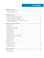
Contents
Contents 3

Actualización de BIOS.........................................................................................................................................................40
Jumper Settings................................................................................................................................................................... 41
Contraseña del sistema y de configuración...................................................................................................................... 41
Asignación de contraseña del sistema y de configuración........................................................................................ 41
Eliminación o modificación de una contraseña del sistema y de configuración existente.................................... 42
Desactivación de la contraseña del sistema...............................................................................................................42
5 Specifications............................................................................................................................ 44
6 Contacting Dell.......................................................................................................................... 47
4 Contents

Manipulación del equipo
Temas:
• Before Working Inside Your Computer
• Turning Off Your Computer
• After Working Inside Your Computer
Before Working Inside Your Computer
Use the following safety guidelines to help protect your computer from potential damage and to help to ensure your personal safety.
Unless otherwise noted, each procedure included in this document assumes that the following conditions exist:
• You have read the safety information that shipped with your computer.
• A component can be replaced or--if purchased separately--installed by performing the removal procedure in reverse order.
NOTA: Desconecte todas las fuentes de energía antes de abrir la cubierta o los paneles del equipo. Una vez que termine
de trabajar en el interior del equipo, vuelva a colocar todas las cubiertas, paneles y tornillos antes de conectarlo a la
fuente de energía.
NOTA: Before working inside your computer, read the safety information that shipped with your computer. For
additional safety best practices information, see the Regulatory Compliance Homepage at www.dell.com/
regulatory_compliance
PRECAUCIÓN: Many repairs may only be done by a certified service technician. You should only perform
troubleshooting and simple repairs as authorized in your product documentation, or as directed by the online or
telephone service and support team. Damage due to servicing that is not authorized by Dell is not covered by your
warranty. Read and follow the safety instructions that came with the product.
PRECAUCIÓN: To avoid electrostatic discharge, ground yourself by using a wrist grounding strap or by periodically
touching an unpainted metal surface, such as a connector on the back of the computer.
PRECAUCIÓN: Handle components and cards with care. Do not touch the components or contacts on a card. Hold a
card by its edges or by its metal mounting bracket. Hold a component such as a processor by its edges, not by its pins.
PRECAUCIÓN: When you disconnect a cable, pull on its connector or on its pull-tab, not on the cable itself. Some cables
have connectors with locking tabs; if you are disconnecting this type of cable, press in on the locking tabs before you
disconnect the cable. As you pull connectors apart, keep them evenly aligned to avoid bending any connector pins. Also,
before you connect a cable, ensure that both connectors are correctly oriented and aligned.
NOTA: The color of your computer and certain components may appear differently than shown in this document.
To avoid damaging your computer, perform the following steps before you begin working inside the computer.
1. Ensure that your work surface is flat and clean to prevent the computer cover from being scratched.
2. Turn off your computer (see Turning Off Your Computer).
PRECAUCIÓN:
To disconnect a network cable, first unplug the cable from your computer and then unplug the cable
from the network device.
3. Disconnect all network cables from the computer.
4. Disconnect your computer and all attached devices from their electrical outlets.
5. Press and hold the power button while the computer is unplugged to ground the system board.
6. Remove the cover.
1
Manipulación del equipo 5

PRECAUCIÓN: Before touching anything inside your computer, ground yourself by touching an unpainted metal
surface, such as the metal at the back of the computer. While you work, periodically touch an unpainted metal
surface to dissipate static electricity, which could harm internal components.
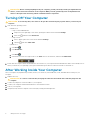
Turning Off Your Computer
PRECAUCIÓN: To avoid losing data, save and close all open files and exit all open programs before you turn off your
computer.
1. Shut down the operating system:
• In Windows 8:
• Using a touch-enabled device:
a. Swipe in from the right edge of the screen, opening the Charms menu and select Settings.
b.
Select the
and then select Shut down
• Using a mouse:
a. Point to upper-right corner of the screen and click Settings.
b.
Click the
and select Shut down.
• In Windows 7:
a. Click Start
.
b. Click Shut Down.
or
a. Click Start
.
b. Click the arrow in the lower-right corner of the Start menu as shown below, and then click Shut Down..
2. Ensure that the computer and all attached devices are turned off. If your computer and attached devices did not automatically turn off
when you shut down your operating system, press and hold the power button for about 6 seconds to turn them off.
After Working Inside Your Computer
After you complete any replacement procedure, ensure you connect any external devices, cards, and cables before turning on your
computer.
1. Replace the cover.
PRECAUCIÓN:
To connect a network cable, first plug the cable into the network device and then plug it into the
computer.
2. Connect any telephone or network cables to your computer.
3. Connect your computer and all attached devices to their electrical outlets.
4. Turn on your computer.
5. If required, verify that the computer works correctly by running the Dell Diagnostics.
6
Manipulación del equipo

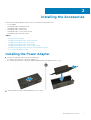
Installing the Accessories
This section provides detailed information on how to install the following accessories:
• Power Adapter
• Dell OptiPlex Micro Dual VESA Mount
• Dell OptiPlex Micro VESA Mount
• Dell OptiPlex Micro Vertical Stand
• Dell OptiPlex Micro Console with DVD-RW
• Dell OptiPlex Micro All-in-One Mount
Topics:
• Installing the Power Adapter
• Installing the Dell OptiPlex Micro Dual VESA Mount
• Installing the Dell OptiPlex Micro VESA Mount
• Installing the Dell OptiPlex Micro Vertical Stand
• Installing the Dell OptiPlex Micro Console with DVD-RW
• Installing the Dell OptiPlex Micro All-in-One Mount Behind the Monitor
• List of Compatible Monitor Models
Installing the Power Adapter
1. Perform the following steps as shown in the illustration:
a) Slide to open the cover of the power adapter [1].
b) Install the power cable to the power adapter and place the power adapter in the box [ 2,3].
2. Insert the cable into the box and slide back the cover to lock it.
2
Installing the Accessories 7

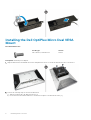
Installing the Dell OptiPlex Micro Dual VESA
Mount
Recommended Screws:
Screw Type
Used in
M4 x L10 mm, Pan head screw Monitor
Prerequisite: Install the power adapter.
1. Align the dual VESA mount behind the monitor and tighten the screws to secure the dual VESA mount to the monitor.
2. Perform the following steps as shown in the illustration:
a) Slide the computer into the dual VESA mount. [1]
b) Rotate the screw in clockwise direction to secure the computer to the dual VESA mount. [2]
8
Installing the Accessories

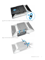
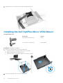
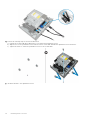
3. Slide the power adapter case through the grooves at the bottom of the dual dual VESA mount to lock it.
4. Connect all the cables and antenna to the computer.
Installing the Accessories
9

5. Tighten the screws to secure the arm stand to the dual VESA mount.
Installing the Dell OptiPlex Micro VESA Mount
Recommended Screws:
Screw Type
Used in
M4 x L10 mm, Pan head screw Monitor
ST4 x L13 mm, Wooden screw Wooden table
Prerequisite: Install the power adapter.
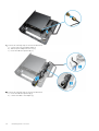
1. Perform the following steps as shown in the illustration:
a) Tighten the screws to secure the VESA mount to the table.
b) Slide the computer into the VESA mount [1].
c) Tighten the screw to secure the computer to the VESA mount [2].
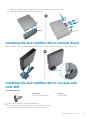
2. Perform the following steps as shown in the illustration:
10
Installing the Accessories

a) Slide the power adapter case through the grooves at the bottom of the VESA mount to lock it.
b) Connect all the cables and install antenna to the computer.
Installing the Dell OptiPlex Micro Vertical Stand
Align the computer on the vertical stand and ensure the tab on the vertical stand fits into the groove or notch on the system.
Installing the Dell OptiPlex Micro Console with
DVD-RW
Recommended Screws:
Screw Type
Used in
ST4 x 13 mm, Wooden screw Wooden table
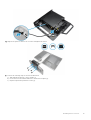
1. Perform the following steps as shown in the illustration:
a) Loosen the screws that secure the cover to the optical drive console [1].
b) Slide and lift the cover upwards to remove it from the console [2].
Installing the Accessories
11

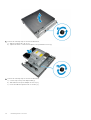
2. Perform the following steps as shown in the illustration:
a) Slide the computer into the slot [1].
b) Tighten the screw to secure the computer to the optical drive console [2].
3. Perform the following steps as shown in the illustration:
a) Cut the strap of the power adapter cable [1].
b) Slide and insert the power adapter into the slot [2].
c) Route the cable through the notch to secure it [3].
12
Installing the Accessories

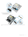
4. Perform the following steps as shown in the illustration:
a) Open the cable management clip [1].
b) Lift the antenna cable out [2].
c) Connect the antenna cable to the antenna connector [3].
5. Route the USB cables through the cable management clip and connect them to the computer. Close the cable management clip.
Installing the Accessories
13

6. Perform the following steps as shown in the illustration:
a) Prepare the wooden table by installing screws for mounting the optical drive console.
b) Align the slots on the optical drive console with the screws on the table and slide the optical drive console and lock it.
c) Tighten the screws to secure the optical drive console to the wooden table.
7. Install the antenna to the optical drive console.
14
Installing the Accessories

8. Perform the following steps as shown in the illustration:
a) Slide and insert the cover to its position [1].
b) Tighten the screws to secure the cover to the chassis [2].
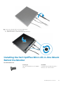
Installing the Dell OptiPlex Micro All-in-One Mount
Behind the Monitor
Recommended Screws:
Screw Type
Used with
M4 X L8 mm, pitch 0.7 mm, self-tapping
screw
PUZ plate without thread screw holes—
Dell P,U,PU,UZ- series monitors
Installing the Accessories 15

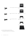
M4 X L8 mm, pitch 0.5 mm, machine screw PUZ plate with thread screw holes — Dell
P,U,PU,UZ- series monitors
M3 X L8 mm, pitch 0.5 mm, self-tapping
screw
E Plate without thread screw holes— Dell
E-series monitors
M3 X L8 mm, pitch 0.35 mm, machine
screw
E Plate with thread screw holes— Dell E-
series monitors
U Plate — Universal monitors
1. Perform the following steps as shown in the illustration:
a) Remove the screws that secure the cover to the chassis [1].
b) Slide and lift the cover upwards to remove it from the chassis [2].
16
Installing the Accessories

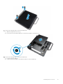
2. Perform the following steps as shown in the illustration:
a) Slide the computer into the slot [1].
b) Rotate the screw in clockwise direction to secure the computer to the chassis [2].
3. Perform the following steps as shown in the illustration:
a) Lift up the antenna cable [1].
b) Connect the antenna cable to the antenna connector on the computer [2].
Installing the Accessories
17

4. Perform the following steps as shown in the illustration:
a) Cut the strap of power adapter cable [1].
b) Slide the power adapter into the slot [2].
c) Route the cable through the clip [3].
5. Perform the following steps as shown in the illustration:
a) Route the cable through the clip [1].
b) Connect the cable to the adapter [2].
18
Installing the Accessories

6. Align the PUZ plate to the bottom of monitor and tighten the screws.
7. Perform the following steps as shown in the illustration:
a) Slide and lock the chassis to the PUZ plate [1].
b) Rotate the screw in clockwise direction to secure the computer [2].
c) Flip the computer along with the monitor [3].
Installing the Accessories
19

8. Perform the following steps as shown in the illustration:
a) Connect all the cables to the computer.
b) Slide the cover to its original position [1].
c) Tighten the screws to secure the cover to the chassis [2].
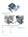
List of Compatible Monitor Models
E-Plate
P/U-Plate and UZ-Plate U-Plate
E1715S P1914S Supports all monitor models that are not
compatible with E-Plate / PUZ-Plate
displays.
E1914H P2014H
E2014H P2214H
E2015Hv P2314H
E2214H / E2214Hv P2714H
E2215Hv P2715Q
E2314H UP2414Q
20 Installing the Accessories

E-Plate P/U-Plate and UZ-Plate U-Plate
E2414H UP3214Q
E2715H UZ2215H
UZ2315H
UZ2715H
S2415H
S2715H
Installing the Accessories 21

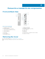
Extracción e instalación de componentes
Front and Back View
Figure 1. Front and Back View
1.
power button or power light 2. hard-drive activity light
3. headset connector 4. microphone connector
5. Wi-Fi antenna connector (optional) 6. serial and PS2 connector (optional)
7. USB 2.0 connector (hibernate wake-up) 8. security-cable slot
9. USB 2.0 connectors 10. padlock ring
11. USB 3.0 connectors 12. cable holder
13. service tag 14. network connector (Integrated Connector Module)
15. VGA connector 16. DisplayPort connector
17. power cable connector
Removing the Cover
1. Follow the procedures in Before Working Inside Your Computer.
2. Rotate the power cable clip to the position as shown in the illustration.
3
22 Extracción e instalación de componentes

3. Perform the following steps as shown in the illustration:
a) Remove the screw that secures the cover to the computer [1].
b) Slide the cover outwards [2].
c) Lift the cover up to remove it from the computer [3].
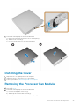
Installing the Cover
1. Align the cover to its original position on the computer.
2. Tighten the screw to secure the cover to the computer.
3. Follow the procedures in After Working Inside Your Computer.
Removing the Processor Fan Module
1. Follow the procedures in Before Working Inside Your Computer.
2. Remove the cover.
3. Perform the following steps as shown in the illustration:
a) Press the securing tabs on the sides [1].
b) Slide the processor fan module outwards [2].
c) Lift the processor fan module away from the computer [3].
Extracción e instalación de componentes
23

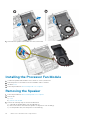
4. Disconnect the speaker and fan cables from the system board.
Installing the Processor Fan Module
1. Connect the speaker and fan cable to the connectors on the system board.
2. Place the processor fan module on the slot and slide it until it is secured.
3. Install the cover.
4. Follow the procedures in After Working Inside Your Computer.
Removing the Speaker
1. Follow the procedures in Before Working Inside Your Computer.
2. Remove the:
a) cover
b) processor fan module
3. Perform the following steps as shown in the illustration:
a) Unthread the speaker cables from the cable clips [1].
b) Remove the screws that secure the speakers to the processor fan module [2].
c) Lift the speakers away from the processor fan module [3].
24
Extracción e instalación de componentes

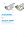
NOTE: The speaker is a part of the processor fan module.
Installing the Speaker
1. Place and align the speakers on the processor fan module.
2. Tighten the screws to secure the speaker to the processor fan module.
3. Thread the cables through the cable clips to secure it.
4. Install:
a) processor fan module
b) cover
5. Follow the procedures in After Working Inside Your Computer.
Removing the Hard Drive
1. Follow the procedures in Before Working Inside Your Computer.
2. Remove the cover.
3. Perform the following steps as shown in the illustration:
a) Press the securing tabs to release the hard-drive assembly [1].
b) Slide the hard-drive assembly to release it from the slot [2].
c) Lift the hard-drive assembly away from the computer [3].
Extracción e instalación de componentes
25

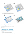
4. Perform the following steps as shown in the illustration:
a) Pry the hard-drive bracket apart to release the hard drive [1].
b) Lift the hard drive away from hard-drive bracket [2].
Installing the Hard Drive
1. Insert the hard drive into the hard-drive bracket.
2. Align and place the hard-drive assembly to its slot on the computer.
3. Install the cover.
4. Follow the procedures in After Working Inside Your Computer.
Removing the Heatsink
1. Follow the procedures in Before Working Inside Your Computer.
2. Remove the:
a) cover
b) processor fan module
3. Perform the following steps as shown in the illustration:
a) Remove the screws that secure the heatsink to the system board [1].
26
Extracción e instalación de componentes

b) Lift the heatsink away from the system board [2].
Installing the Heatsink
1. Place the heat sink on the system board.
2. Tighten the screws to secure the heatsink.
3. Install:
a) processor fan module
b) cover
4. Follow the procedures in After Working Inside Your Computer.
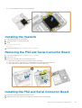
Removing the PS2 and Serial Connector Board
1. Follow the procedures in Before Working Inside Your Computer.
2. Remove the cover.
3. Perform the following steps as shown in the illustration:
a) Disconnect the cable from the PS2 and serial connector board [1].
b) Remove the screws that secure the PS2 and serial connector board to the base panel [2].
c) Slide and lift the PS2 and serial connector board away from the computer [3].
Installing the PS2 and Serial Connector Board
1. Place the PS2 and serial connector board into its slot.
2. Tighten the screws that secure the PS2 and serial connector board to the base panel.
Extracción e instalación de componentes
27

3. Connect the cable to the PS2 and serial connector board.
4. Install the cover.
5. Follow the procedures in After Working Inside Your Computer.
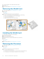
Removing the WLAN Card
1. Follow the procedures in Before Working Inside Your Computer.
2. Remove the:
a) cover
b) hard drive
3. Perform the following steps as shown in the illustration:
a) Remove the screw that secures the WLAN card to the system board [1].
b) Remove the WLAN bracket from the system board [2].
c) Disconnect the WLAN cables [3].
d) Slide the WLAN card from the system board [4].
Installing the WLAN Card
1. Align and place the WLAN card on the connector.
2. Connect the WLAN cables.
3. Place the WLAN bracket into its slot.
4. Tighten the screws to secure the WLAN card to the system board.
5. Install:
a) hard drive
b) cover
6. Follow the procedures in After Working Inside Your Computer.
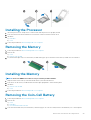
Removing the Processor
1. Follow the procedures in Before Working Inside Your Computer.
2. Remove the:
a) hard drive
b) cover
3. Perform the following steps as shown in the illustration:
a) Press the release lever down [1].
b) Move the lever outward to release it from the retention hook that secures it [2].
c) Lift the processor cover and remove the processor from its socket [3].
28
Extracción e instalación de componentes

Installing the Processor
1. Insert the processor into the processor socket. Ensure that the processor is properly seated.
2. Press the release lever down and then move it inward to secure it with the retention hook.
3. Install the:
a) hard drive
b) cover
4. Follow the procedures in After Working Inside Your Computer.
Removing the Memory
1. Follow the procedures in Before Working Inside Your Computer.
2. Remove the:
a) cover
b) processor fan module
3. Pry the retention clips away from the memory module until it pops-up. Lift and remove the memory module from its connector.
Installing the Memory
NOTE: Please use DIMM 2 slot if there is only one memory module available.
1. Align the notch on the memory-card with the tab in the system-board connector.
2. Press down on the memory module until the retention clips spring back to secure them in place.
3. Install the:
a) processor fan module
b) cover
4. Follow the procedures in After Working Inside Your Computer.
Removing the Coin-Cell Battery
1. Follow the procedures in Before Working Inside Your Computer.
2. Remove the:
a) cover
b) hard drive
c) PS2 and serial connector board
3. Press the release latch away from the battery. The battery pops out from the socket; lift the coin-cell battery out of the computer.
Extracción e instalación de componentes
29

Installing the Coin-Cell Battery
1. Place the coin-cell battery into its slot on the system board.
2. Press the coin-cell battery downward until the release latch springs back into place and secures it.
3. Install the:
a) PS2 and serial connector board
b) hard drive
c) cover
4. Follow the procedures in After Working Inside Your Computer.
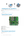
System Board Layout
The following image displays the system board layout of the computer.
1. processor socket
2. processor fan connector
3. speaker connector
4. memory connectors ( SODIMM sockets)
5. WLAN connector
6. SATA HDD connector
7. coin-cell battery
8. PS2 and serial connector
Removing the System Board
1. Follow the procedures in Before Working Inside Your Computer.
2. Remove the:
30
Extracción e instalación de componentes

a) cover
b) processor fan module
c) hard drive
d) heatsink
e) memory
f) processor
g) PS2 or serial connector board
h) WLAN card
i) coin-cell battery
3. Perform the following steps as shown in the illustration.
a) Remove the screws that secure the hard-drive holder to the system board [1].
b) Lift the hard drive holder away from the system board [2].
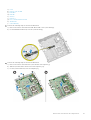
4. Perform the following steps as shown in the illustration.
a) Remove the screws that secure the system board to the computer [1].
b) Slide the system board to release it from the computer [2,3].
c) Lift the system board away from the computer [4].
Extracción e instalación de componentes
31

Installing the System Board
1. Place the system board on the computer.
2. Tighten the screws to secure the system board to the base panel.
3. Place the hard drive holder on the system board.
4. Tighten the screws that secure the hard-drive holder to the system board.
5. Install:
a) coin-cell battery
b) WLAN card
c) PS2 or serial connector board
d) processor
e) memory
f) heatsink
g) hard drive
h) processor fan module
i) cover
6. Follow the procedures in After Working Inside Your Computer.
32 Extracción e instalación de componentes

Configuración del sistema
System Setup (Configuración del sistema) permite administrar el hardware del equipo y especificar las opciones de nivel de BIOS. En
System Setup (Configuración del sistema), puede:
• Modificar la configuración de la NVRAM después de añadir o eliminar hardware.
• Ver la configuración de hardware del sistema.
• Habilitar o deshabilitar los dispositivos integrados.
• Definir umbrales de administración de energía y de rendimiento.
• Administrar la seguridad del equipo.
Temas:
• Secuencia de arranque
• Teclas de navegación
• System Setup Options
• Actualización de BIOS
• Jumper Settings
• Contraseña del sistema y de configuración
Secuencia de arranque
La secuencia de arranque le permite omitir el orden de dispositivos de arranque definido en la configuración del sistema y arrancar
directamente desde un dispositivo específico (por ejemplo, la unidad óptica o la unidad de disco duro). Durante la autoprueba de encendido
(POST), cuando aparezca el logotipo de Dell, puede hacer lo siguiente:
• Acceder al programa de configuración del sistema al presionar la tecla <F2>
• Activar el menú de inicio de una vez al presionar la tecla <F12>
El menú de arranque de una vez muestra los dispositivos desde los que puede arrancar, incluida la opción de diagnóstico. Las opciones del
menú de arranque son las siguientes:
• Unidad extraíble (si está disponible)
• Unidad STXXXX
NOTA: XXX denota el número de la unidad SATA.
• Unidad óptica
• Diagnóstico
NOTA: Al elegir Diagnósticos, aparecerá la pantalla ePSA diagnostics (Diagnósticos de ePSA).
La pantalla de secuencia de inicio también muestra la opción de acceso a la pantalla de la configuración del sistema.
Teclas de navegación
La siguiente tabla muestra las teclas de navegación de configuración del sistema.
NOTA:
Para la mayoría de las opciones de configuración del sistema, se registran los cambios efectuados, pero no se
aplican hasta que se reinicia el sistema.
Tabla 1. Teclas de navegación
Teclas Navegación
Flecha hacia arriba Se desplaza al campo anterior.
Flecha hacia abajo Se desplaza al campo siguiente.
<Intro> Permite introducir un valor en el campo seleccionado, si se puede, o seguir el vínculo del campo.
Barra espaciadora Amplía o contrae una lista desplegable, si procede.
4
Configuración del sistema 33

Teclas Navegación
<Tab> Se desplaza a la siguiente área de enfoque.
NOTA: Solo para el explorador de gráficos estándar.
<Esc> Se desplaza a la página anterior hasta que vea la pantalla principal. Si presiona la tecla <Esc> en la pantalla
principal, aparecerá un mensaje que le solicitará guardar los cambios y reiniciar el sistema.
<F1> Muestra el archivo de ayuda de System Setup (Configuración del sistema).
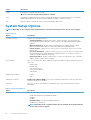
System Setup Options
NOTE: Depending on the computer and its installed devices, the items listed in this section may or may not appear
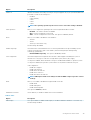
Table 2. General
Option Description
System Information Displays the following information:
• System Information - Displays BIOS Version, Service Tag, Asset Tag, Ownership Tag,
Ownership Date, Manufacture Date, Express Service Code, and Signed Firmware Update is
enabled.
• Memory Information - Displays Memory Installed, Memory Available, Memory Speed,
Memory Channels Mode, Memory Technology, DIMM 1 Size, and DIMM 2 Size.
• PCI Information - Displays SLOT1, SLOT2, SLOT3 (For MT chassis only), SLOT4 (For MT
chassis only)
• Processor Information - Displays Processor Type, Core Count, Processor ID, Current Clock
Speed, Minimum Clock Speed, Maximum Clock Speed, Processor L2 Cache, Processor L3
Cache, HT Capable, and 64-Bit Technology.
• Device Information - Displays SATA-0, SATA-1, SATA-2(For MT chassis only), LOM MAC
Address, Audio Controller, Video Controller.
Boot Sequence Allows you to specify the order in which the computer attempts to find an operating system. The
options are:
• Diskette drive
• Internal HDD
• USB Storage Device
• CD/DVD/CD-RW Drive
• Onboard NIC
Advanced Boot Options
• Legacy
• UEFI
Advance Boot Options Enable Legacy Option ROMs - This option is required for legacy boot mode. This option is not
allowed if Secure Boot is enabled.
Date/Time Allows you to set the date and time. The changes to the system date and time takes effect
immediately.
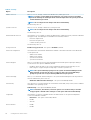
Table 3. System Configuration
Option Description
Integrated NIC Allows you to enable or disable the integrated network card. You can set the integrated NIC to:
• Enable UEFI Network Stack (disable by default)
• Disabled
• Enabled
• Enabled w/PXE- This option is enabled by default.
• Enabled w/Cloud Desktop
NOTE: Depending on the computer and the devices installed, the items listed in this
section may or may not appear.
34 Configuración del sistema

Option Description
Serial Port
Identifies and defines the serial port settings. This option appear only if your system installed serial
port card. You can set the serial port to:
• Disabled
• COM1 (Default)
• COM2
• COM3
• COM4
NOTE: The operating system may allocate resources even if the setting is disabled.
SATA Operation Allows you to configure the operating mode of the integrated hard drive controller.
• Disabled - The SATA controllers are hidden.
• ATA - SATA is configured for ATA mode.
• AHCI - SATA is configured for AHCI mode. This option is enabled by default.
Drives Allows you to enable or disable the on-board drive:
• SATA-0
• SATA-1
• SATA-2(For MT chassis only)
Default setting: All enabled.
SMART Reporting This field controls if the hard drive errors for the integrated drives are reported during system
startup. This technology is part of the SMART (Self Monitoring Analysis and Reporting
Technology) specification.
• Enable SMART Reporting - This option is disabled by default.
USB Configuration This field configures the integrated USB controller. If Boot Support is enabled, the system is
allowed to boot any type of USB mass storage devices (HDD, memory key, floppy).
If USB port is enabled, device attached to this port is enabled and available for operation system.
If USB port is disabled, the operation system cannot see any device attached to this port.
USB configuration:
• Enable Boot Support
• Enable USB 3.0 Ports
• Enable Dual USB 2.0 Ports
• Enable Front USB Ports
• Enable Rear Dual USB 2.0 Ports
NOTE: USB keyboard and mouse always work in the BIOS setup irrespective of these
settings.
Audio Allows you to enable or disable the integrated audio controller.
• Enable Audio
• Enable Microphone
• Enable Internal Speaker
This option is enabled by default.
Miscellaneous Devices These fields let you enable or disable various on board devices.
Table 4. Video
Option Description
Multi-Display This option enables or disables Multi-Display. It should be enabled for Windows 7 32/64-bit only.
Default setting: Disabled
Configuración del sistema 35

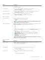
Table 5. Security
Option Description
Admin Password Allows you to set, change, or delete the administrator (admin) password.
NOTE: You must set the admin password before you set the system or hard drive
password. Deleting the admin password automatically deletes the system password
and the hard drive password.
NOTE: Successful password changes take effect immediately.
Default Setting: Not set
System Password Allows you to set, change or delete the system password.
NOTE: Successful password changes take effect immediately.
Default Setting: Not set
Internal HDD-0 Password This field lets you set, change, or delete the administrator (admin) password (sometimes called the
setup password). The admin password enables several security features.
• Enter the old password
• Enter the new password
• Confirm the new password
Default Setting: Not set
Strong Password
Enable strong password - This option is disabled by default.
Password Configuration This field controls the minimum and maximum number of characters allowed for the admin and
system passwords.
• Admin Password Min
• Admin Password Max
• System Password Min
• System Password Max
Password Bypass Allows you to bypass the System Password and the internal HDD password prompts during a
system restart. This option is disabled by default.
• Disabled - Always prompt for the system and internal HDD password when they are set.
• Reboot Bypass - Bypass the password prompts on restarts (warm boots).
NOTE: The system will always prompt for the system and internal HDD passwords
when powered on from the off state (a cold boot). Also, the system will always
prompt for passwords on any module bay HDDs that may be present.
Password Change Allows you to determine whether changes to the system and hard disk passwords are permitted
when an administrator password is set.
• Allow Non-Admin Password Changes - This option is enabled by default.
TPM Security This option lets you control whether the Trusted Platform Module (TPM) in the system is enabled
and visible to the operating system.
TPM Security - This option is disabled by default.
NOTE: Activation, deactivation, and clear options are not affected if you load the
setup program's default values. Changes to this option take effect immediately.
Computrace This field lets you activate or disable the BIOS module interface of the optional Computrace
Service from Absolute Software.
• Deactivate - This option is selected by default.
• Disable
• Activate
Chassis Intrusion
• Enable
• Disable
36 Configuración del sistema

Option Description
• On-Silent
Default Setting: Disabled
CPU XD Support Allows you to enable or disable the execute disable mode of the processor.
• Enable CPU XD Support - This option is enabled by default.
Admin Setup Lockout Allows you to enable or disable the option to enter setup when an admin password is set.
• Enable Admin Setup Lockout - This option is not set by default.
HDD Protection Support Allows you to enable or disable the HDD Protection feature
• HDD Protection Support - This option is not set by default.
Table 6. Secure Boot
Secure Boot Enable Allows you to enable or disable Secure Boot feature
• Disabled - This option is selected by default.
• Enabled
NOTE: To enable secure boot, UEFI boot mode must be enabled and Enable Legacy
Option ROMs must be disabled or turned off.
Expert key Management Allows you to manipulate the security key databases only if the system is in Custom Mode. The
Enable Custom Mode option is disabled by default. The options are:
• PK
• KEK
• db
• dbx
If you enable the Custom Mode, the relevant options for PK, KEK, db, and dbx appear. The
options are:
• Save to File- Saves the key to a user-selected file
• Replace from File- Replaces the current key with a key from a user-selected file
• Append from File- Adds a key to the current database from a user-selected file
• Delete- Deletes the selected key
• Reset All Keys- Resets to default setting
• Delete All Keys- Deletes all the keys
NOTE: If you disable the Custom Mode, all the changes made will be erased and the
keys will restore to default settings.
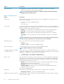
Table 7. Performance
Option Description
Multi Core Support Specifies whether the process will have one or all cores enabled. The performance of some
applications will improve with the additional cores.
• All - This option is enabled by default
• 1
• 2
Intel SpeedStep Allows you to enable or disable the Intel SpeedStep mode of the processor.
• Enable Intel SpeedStep
- This option is enabled by default.
C States Control Allows you to enable or disable the additional processor sleep states.
• C States
- This option is enabled by default.
Configuración del sistema 37

Option Description
Limit CPUID Value This field limits the maximum value the processor Standard CPUID Function will support.
• Enable CPUID Limit - This option is not set by default.
NOTE: Some Operating system will not complete installation when the maximum
CPUID Function is greater than 3.
Table 8. Power Management
Option Description
AC Recovery Specifies how the computer will respond when AC power is applied after an AC power loss. You
can set the AC Recovery to:
• Power Off - This option is enabled by default.
• Power On
• Last Power State
Auto On Time This option sets the time of the day when you would like the system to turn on automatically. Time
is kept in standard 12-hour format (hour:minutes:seconds). The startup time can be changed by
typing the values in the time and A.M./P.M. fields.
• Disabled - The system will not automatically power up. This option is selected by default.
• Every Day - The system will power up every day at the time you specified above .
• Weekdays - The system will power up Monday through Friday at the time you specified
above.
• Select Days - The system will power up on days selected above at the time you specified
above.
NOTE: This feature does not work if you turn off your computer using the switch on
a power strip or surge protector or if Auto Power is set to disabled.
Deep Sleep Control Allows you to define the controls when Deep Sleep is enabled.
• Disabled
• Enabled in S5 only
• Enabled in S4 and S5 - This option is enabled by default.
Fan Control Override Controls the speed of the system fan. This option is disabled by default.
NOTE: When enabled, the fan runs at full speed.
USB Wake Support from Standby
(S3)/Hibernation (S4)
This option allows you to enable USB devices (keyboard or mouse) to wake the computer from
standby (S3) or hibernation (S4). For waking up the computer from hibernation, you must connect
USB device to a specific rear USB port(next to RJ45 connector).
• USB Wake Support From Standby is enabled by default.
• USB Wake Support From Hibernation is disabled by default.
Wake on LAN This option allows the computer to power up from the off state when triggered by a special LAN
signal. Wake-up from the Standby state is unaffected by this setting and must be enabled in the
operating system. This feature only works when the computer is connected to AC power supply.
The options differ based on the form factor.
• Disabled - Does not allow the system to power on by special LAN signals when it receives a
wake-up signal from the LAN or wireless LAN.
• LAN Only - Allows the system to be powered on by special LAN signals.
• LAN with PXE Boot - Allows the system to be powered on by special LAN signals. After
waking the system, do a PXE boot.
This option is Disabled by default.
Block Sleep This option lets you block entering to sleep (S3 state) in operating system environment.
• Block Sleep (S3 state) - This option is disabled by default.
Intel® Smart Connect Technology This Intel® Smart Connect Technology feature will periodically sense nearby wireless connections
while the system is asleep.
38 Configuración del sistema

Option Description
Default setting: Disabled
Table 9. POST Behavior
Option Description
Numlock LED Specifies if the NumLock function can be enabled when the system boots. This option is enabled
by default.
Keyboard Errors Specifies whether keyboard related errors are reported when it boots. This option is enabled by
default.
Table 10. Virtualization Support
Option Description
Virtualization This option specifies whether a Virtual Machine Monitor (VMM) can utilize the additional hardware
capabilities provided by Intel Virtualization technology.
• Enable Intel Virtualization Technology - This option is enabled by default.
Table 11. Wireless
Option Description
Wireless Device Enable Allows you to enable or disable the internal wireless devices.
• WLAN/WiGig
• Bluetooth
All options are enabled by default.
Table 12. Maintenance
Option Description
Service Tag Displays the service tag of your computer.
Asset Tag Allows you to create a system asset tag if an asset tag is not already set. This option is not set by
default.
SERR Messages Controls the SERR message mechanism. Some graphics cards require that the SERR message
mechanism be disabled. This option is enabled by default.
Table 13. Cloud Desktop
Option Description
Server Lookup Method Specifies how the Cloud Desktop software will looks up the server addresses.
• Static IP
• DNS - This option is enabled by default.
NOTE: This field is only relevant when the
Integrated NIC
control in the
System
Configuration
group is set to
Enable with Cloud Desktop
.
Server IP Address Specifies the primary static IP address of the Cloud Desktop server with which the client software
communicates. The default IP address is 255.255.255.255.
NOTE: This field is only relevant when the
Integrated NIC
control in the
System
Configuration
group is set to
Enable with Cloud Desktop
.
Server Port Specifies the primary IP port of the Cloud Desktop, which is used by the client to communicate.
The default IP port is 06910.
NOTE: This field is only relevant when the
Integrated NIC
control in the
System
Configuration
group is set to
Enable with Cloud Desktop
.
Client Address Method Specifies how the client obtains the IP address.
Configuración del sistema 39

Option Description
• Static IP
• DHCP - This option is enabled by default.
NOTE: This field is only relevant when the
Integrated NIC
control in the
System
Configuration
group is set to
Enable with Cloud Desktop
.
Client IP Address Specifies the static IP address of the client. The default IP address is 255.255.255.255.
NOTE: This field is only relevant when the
Integrated NIC
control in the
System
Configuration
group is set to
Enable with Cloud Desktop
.
Client SubnetMask Specifies the subnet mask of the client. The default setting is 255.255.255.255.
NOTE: This field is only relevant when the
Integrated NIC
control in the
System
Configuration
group is set to
Enable with Cloud Desktop
.
Client Gateway Specifies the gateway IP address of the client. The default setting is 255.255.255.255.
NOTE: This field is only relevant when the
Integrated NIC
control in the
System
Configuration
group is set to
Enable with Cloud Desktop
.
Advanced Specifies for Advanced debugging
• Verbose Mode - This option is not set by default.
NOTE: This Option is only relevant when the integrated NIC control in the System
Configuration group is set to enable with Cloud Desktop.
Table 14. System Logs
Option Description
BIOS events Displays the system event log and allows you to clear the log.
• Clear Log
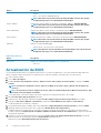
Actualización de BIOS
Se recomienda actualizar el BIOS (configuración del sistema) si se sustituye la placa base o si hay una actualización disponible. Para
laptops, asegúrese de que la batería de su computadora esté totalmente cargada y conectada a una toma de corriente.
1. Vuelva a iniciar el equipo.
2. Vaya a dell.com/support.
3. Escriba la Service Tag (etiqueta de servicio) o Express Service Code (código de servicio rápido) y haga clic en Submit
(enviar).
NOTA:
Para ubicar la etiqueta de servicio, haga clic en Where is my Service Tag? (¿Dónde está mi etiqueta de
servicio?)
NOTA: Si no puede encontrar su etiqueta de servicio, haga clic en Detect My Product (Detectar mi producto). Siga
las instrucciones que figuran en pantalla.
4. Si no puede ubicar o encontrar la etiqueta de servicio, haga clic en la categoría de producto de su equipo.
5. Elija el Product Type (Tipo de producto) de la lista.
6. Seleccione el modelo del equipo y aparecerá la página Product Support (Soporte técnico del producto) de su equipo.
7. Haga clic en Get drivers (Obtener controladores) y haga clic en View All Drivers (Ver todos los controladores).
Se abre la página de controladores y descargas.
8. En la pantalla de descargas y unidades, bajo la lista desplegable de Operating System (sistema operativo), seleccione BIOS.
9. Identifique la última versión de archivo BIOS y haga clic en Download File (descargar archivo).
También puede hacer un análisis para conocer qué controladores requieren una actualización. Para realizar esta acción para su
producto, haga clic en Analyze System for Updates (Analizar el sistema en busca de actualizaciones) y siga las instrucciones
que aparecen en pantalla.
10. Seleccione su método de descarga preferido en la sección Please select your download method below window (ventana de
selección de método de descarga); haga clic en Download File (descargar archivo).
Aparecerá la ventana File Download (Descarga de archivos).
40
Configuración del sistema

11. Haga clic en Save (Guardar) para guardar el archivo en su equipo.
12. Haga clic en Run (ejecutar) para instalar las configuraciones del BIOS actualizado en su equipo.
Siga las instrucciones que aparecen en pantalla.
Jumper Settings
To change a jumper setting, pull the plug off its pin(s) and carefully fit it down onto the pin(s) indicated on the system board. The
following table displays the system board jumper settings.
Tabla 15. Jumper Settings
Jumper Setting Description
PSWD Default Password features are enabled
RTCRST pin 1 and 2 Real-time clock reset. Can be used for troubleshooting.
Contraseña del sistema y de configuración
Puede crear una contraseña del sistema y una contraseña de configuración para proteger su equipo.
Tipo de
contraseña
Descripción
System Password Es la contraseña que debe introducir para iniciar sesión en el sistema.
Setup password
(Contraseña de
configuración)
Es la contraseña que debe introducir para acceder y realizar cambios a la configuración de BIOS del equipo.
PRECAUCIÓN: Las funciones de contraseña ofrecen un nivel básico de seguridad para los datos del equipo.
PRECAUCIÓN: Cualquier persona puede tener acceso a los datos almacenados en el equipo si no se bloquea y se deja
desprotegido.
NOTA: El equipo se envía con la función de contraseña de configuración y de sistema desactivada.
Asignación de contraseña del sistema y de configuración
Puede asignar una nueva System Password (Contraseña del sistema) o Setup Password (Contraseña de configuración), o
cambiar una existente solo cuando el valor de Password Status (Estado de la contraseña) es Unlocked (Desbloqueado). Si el valor
que se muestra para Password Status (Estado de la contraseña) es Locked (Bloqueado), no podrá cambiar la contraseña del sistema.
NOTA:
Si se desactiva el puente de contraseña, la contraseña del sistema y de configuración existente se elimina y no
necesitará proporcionar una contraseña del sistema para iniciar sesión en el equipo.
Para acceder a System Setup (Configuración del sistema), presione <F2> inmediatamente después del encendido o el reinicio.
1. En la pantalla System BIOS (BIOS del sistema) o System Setup (Configuración del sistema), seleccione System Security
(Seguridad del sistema) y presione <Intro>.
Aparecerá la pantalla de System Security (Seguridad del sistema).
2. En la pantalla System Security (Seguridad del sistema), compruebe que la opción Password Status (Estado de la contraseña)
está en modo Unlocked (Desbloqueado).
3. Seleccione System Password (Contraseña del sistema) introduzca la contraseña y presione <Intro> o <Tab>.
Utilice las siguientes pautas para asignar la contraseña del sistema:
• Una contraseña puede tener hasta 32 caracteres.
• La contraseña puede contener números del 0 al 9.
• Solo se permiten letras en minúsculas. Las mayúsculas no están permitidas.
• Solo se permiten los siguientes caracteres especiales: espacio, (”), (+), (,), (-), (.), (/), (;), ([), (\), (]), (`).
Vuelva a introducir la contraseña del sistema cuando aparezca.
Configuración del sistema
41

4. Introduzca la contraseña del sistema que especificó anteriormente y haga clic en OK (Aceptar).
5. Seleccione Setup Password (Contraseña de configuración), introduzca la contraseña del sistema y presione <Intro> o <Tab>.
Aparecerá un mensaje para que introduzca de nuevo la contraseña de configuración.
6. Introduzca la contraseña de configuración que especificó anteriormente y haga clic en OK (Aceptar).
7. Presione <Esc> y aparecerá un mensaje para que guarde los cambios.
8. Presione <Y> para guardar los cambios.
El equipo se reiniciará.
Eliminación o modificación de una contraseña del sistema y
de configuración existente
Asegúrese de que Password Status (Estado de la contraseña ) esté Unlocked (Desbloqueado) en System Setup (Configuración del
sistema), antes de intentar eliminar o modificar la contraseña del sistema o de configuración existente. No se puede eliminar ni modificar
una contraseña existente del sistema o de configuración si Password Status (Estado de la contraseña) está en Locked (Bloqueado).
Para acceder a System Setup (Configuración del sistema), presione <F2> inmediatamente después del encendido o el reinicio.
1. En la pantalla System BIOS (BIOS del sistema) o System Setup (Configuración del sistema), seleccione System Security
(Seguridad del sistema) y presione <Intro>.
Aparecerá la ventana System Security (Seguridad del sistema).
2. En la pantalla System Security (Seguridad del sistema), compruebe que la opción Password Status (Estado de la contraseña)
está en modo Unlocked (Desbloqueado).
3. Seleccione System Password (Contraseña del sistema), modifique o elimine la contraseña del sistema existente y presione <Intro> o
<Tab>.
4. Seleccione Setup Password (Contraseña de configuración), modifique o elimine la contraseña de configuración existente y
presione <Intro> o <Tab>.
NOTA:
Si cambia la contraseña del sistema o de configuración, introduzca la nueva contraseña cuando se lo soliciten.
Si elimina la contraseña del sistema o de configuración, confirme la eliminación cuando se lo soliciten.
5. Presione <Esc> y aparecerá un mensaje para que guarde los cambios.
6. Presione <Y> para guardar los cambios y salir de la System Setup (Configuración del sistema).
El equipo se reiniciará.
Desactivación de la contraseña del sistema
Las características de seguridad del software del sistema incluyen una contraseña del sistema y una contraseña de configuración. El
puente de la contraseña deshabilita cualquier contraseña actual en uso.
NOTA: También puede utilizar los siguientes pasos para desactivar una contraseña olvidada.
1. Siga los procedimientos que se describen en Antes de manipular el equipo.
2. Quite la cubierta.
3. Identifique el puente de PSWD de la placa base.
4. Extraiga el puente de PSWD de la placa base.
NOTA: La contraseña existente no está desactivadas (borradas) hasta que el equipo inicie sin el puente.
5. Instale la cubierta.
NOTA:
Si asigna una nueva contraseña del sistema o de configuración con el puente PSWD instalado, el sistema
desactivará las nuevas contraseñas la próxima vez que se inicie.
6. Conecte el equipo a una toma de corriente y enciéndalo.
7. Apague el equipo y desconecte el cable de alimentación de la toma de corriente.
8. Quite la cubierta.
9. Coloque el puente de PSWD de la placa base.
10. Instale la cubierta.
11. Siga los procedimientos que se describen en Después de manipular el equipo.
12. Encienda el equipo.
42
Configuración del sistema

13. Vaya a Configuración del sistema y asigne una contraseña del sistema o de configuración. Consulte Configuración de una contraseña
del sistema.
Configuración del sistema 43

Specifications
NOTE: Offerings may vary by region. For more information regarding the configuration of your computer, click Start
(Start icon) > Help and Support, and then select the option to view information about your computer.
Table 16. Processor
Feature Specification
Processor type
• Intel Pentium
• Intel Celeron
• Intel Core i3 series
• Intel Core i5 series
Total cache Up to 8 MB cache depending on processor type
Table 17. Memory
Feature Specification
Memory type DDR3
Memory speed 1600MHz
Memory connectors two DIMM slots
Memory capacity 2 GB, 4 GB, and 8 GB
Minimum memory 2 GB
Maximum memory 16 GB
Table 18. Video
Feature Specification
Integrated Intel HD Graphics
Table 19. Audio
Feature Specification
Integrated Realtek HDA Codec ALC3234
Table 20. Network
Feature Specification
Integrated Realtek RTL8151GD Ethernet capable of 10/100/1000 Mb/s
communication
Table 21. System Information
Feature Specification
System chipset
Intel H81 chipset
Table 22. Expansion Bus
Feature Specification
Bus type USB 2.0, USB 3.0, SATA 3, and PCle G2
Bus speed 480 Mbps, 5 Gbps, 6Gbps, and 5 Gbps,
5
44 Specifications

Table 23. Cards
Feature Specification
WLAN card
Intel Dual Band Wireless-AC 7260 (M.2)
802.11 ac
Bluetooth 4.0
WiDi (Wireless Display)
NOTE: For optimal performance, it is recommended to use the
wireless display feature with an access point that supports 5
GHz standard.
Table 24. Drives
Feature Specification
Internally Accessible: 2.5-inch SATA drive bays
Table 25. External Connectors
Feature Specification
Audio:
Front panel one global headset and one microphone connector ( re-taskable to
headphone )
Network adapter one RJ–45 connector
Serial PS2 or serial connector (optional)
USB 2.0 (Front/Rear/Internal) 1/3/1
USB 3.0 (Front/Rear/Internal) 1/1/0
Video
• 15-pin VGA connector
• one 20-pin Display port connectors
Table 26. Controls and Lights
Feature Specification
Front of the computer:
Power button light White light — Solid white light indicates power-on state; breathing white
light indicates sleep state of the computer.
Drive activity light White light — Blinking white light indicates that the computer is reading
data from or writing data to the hard drive.
Back of the computer:
Link integrity light on integrated network adapter Green — A good 10 Mbps connection exists between the network and the
computer.
Green — A good 100 Mbps connection exists between the network and
the computer.
Orange — A good 1000 Mbps connection exists between the network and
the computer.
Off (no light) — The computer is not detecting a physical connection to
the network.
Network activity light on integrated network adapter Yellow light — A blinking yellow light indicates that network activity is
present.
Power supply diagnostic light Green light — The power supply is turned on and is functional. The power
cable must be connected to the power connector (at the back of the
computer) and the electrical outlet.
Specifications 45

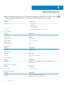
Table 27. Power
Items Wattage Voltage
Power adaptor 65 W 19.5 VDC, 3.34 A
Coin-cell battery 3 V CR2032 lithium coin cell
Table 28. Physical Dimension
Physical Micro Entry
Height 18.2 cm (7.17 inches)
Width 3.6 cm (1.42 inches)
Depth 17.6 cm (6.93 inches)
Weight 1.28 kg (2.82 lb)
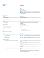
Table 29. Environmental
Feature Specification
Temperature range:
Operating 5 °C to 35 °C (41 °F to 95 °F)
Non-Operating –40 °C to 65 °C (–40 °F to 149 °F)
Relative humidity (maximum):
Operating 20% to 80% (non-condensing)
Non-Operating 5% to 95% (non-condensing)
Maximum vibration:
Operating 0.66 GRMS
Non-Operating 1.37 GRMS
Maximum shock:
Operating 40 G
Non-Operating 105 G
Altitude:
Operating De –15,2 m a 30482000 m (de –50 ft a 10 0006560 ft)
Non-Operating –15.20 m to 10,668 m (–50 ft to 35,000 ft)
Airborne contaminant level G1 or lower as defined by ANSI/ISA-S71.04-1985
46 Specifications

Contacting Dell
NOTE: If you do not have an active internet connection, you can find the contact information on your purchase invoice,
packing slip, bill, or Dell product catalog.
Dell provides several online and telephone-based support and service options. Availability varies by country and product, and some services
may not be available in your area. To contact Dell for sales, technical support, or customer service issues:
Go to Dell.com/contactdell.
6
Contacting Dell 47
-
 1
1
-
 2
2
-
 3
3
-
 4
4
-
 5
5
-
 6
6
-
 7
7
-
 8
8
-
 9
9
-
 10
10
-
 11
11
-
 12
12
-
 13
13
-
 14
14
-
 15
15
-
 16
16
-
 17
17
-
 18
18
-
 19
19
-
 20
20
-
 21
21
-
 22
22
-
 23
23
-
 24
24
-
 25
25
-
 26
26
-
 27
27
-
 28
28
-
 29
29
-
 30
30
-
 31
31
-
 32
32
-
 33
33
-
 34
34
-
 35
35
-
 36
36
-
 37
37
-
 38
38
-
 39
39
-
 40
40
-
 41
41
-
 42
42
-
 43
43
-
 44
44
-
 45
45
-
 46
46
-
 47
47


Dell OptiPlex 3020M El manual del propietario
- Categoría
- Estaciones de trabajo todo en uno
- Tipo
- El manual del propietario
en otros idiomas
- English: Dell OptiPlex 3020M Owner's manual
Artículos relacionados
-
Dell Vostro 5459 El manual del propietario
-
Dell PowerEdge SC1420 El manual del propietario
-
-
-
-
-
-
-
Dell Precision 5510 El manual del propietario
-
Dell Latitude 5289 2-in-1 El manual del propietario