BLACK DECKER A-A6-MKII-K-S El manual del propietario
- Categoría
- Amplificadores de audio para automóviles
- Tipo
- El manual del propietario
Este manual también es adecuado para

A6
Integrated Amplifier | Amplificateur Intégré |
Eingebauter Verstärker | Geïntegreerde versterker |
Amplificatore Integrato | Amplificador integrado |
A-A6MK2-K
Operating Instructions | Mode d’emploi | Bedienungsanleitung |
Handleiding | Istruzioni per I’uso | Manual de instrucciones |
Инструкции по эксплуатации
Discover the benefits of registering your product online at
http://www.pioneer.co.uk
(or http://www.pioneer.eu).
Découvrez les nombreux avantages offerts en enregistrant votre produit en ligne
maintenant sur
http://www.pioneer.fr
(ou http://www.pioneer.eu).
Bitte nutzen Sie die Möglichkeit zur Registrierung Ihres Produktes
unter
http://www.pioneer.de
(oder http://www.pioneer.eu)
Ontdek nu de voordelen van online registratie! Registreer uw Pioneer product via
http://www.pioneer.nl - http://www.pioneer.be
(of http://www.pioneer.eu).
Registra il tuo prodotto su
http://www.pioneer.it
(o http://www.pioneer.eu) e
scopri subito quali vantaggi puoi ottenere!
Registre su producto en
http://www.pioneer.es
(o en http://www.pioneer.eu) Descubra los beneficios de registrarse on-line:
Зарегистрируйте Baшe изделие на
http://www.pioneer-rus.ru
(или
http://www.pioneer.eu). Oзнакомьтесь с преимуществами регистрации в Интернет
BZ02
A6MK2_SYXCN5.book 1 ページ 2009年4月7日 火曜日 午前11時18分

The exclamation point within an equilateral
triangle is intended to alert the user to the
presence of important operating and
maintenance (servicing) instructions in the
literature accompanying the appliance.
The lightning flash with arrowhead symbol,
within an equilateral triangle, is intended to
alert the user to the presence of uninsulated
“dangerous voltage” within the product’s
enclosure that may be of sufficient
magnitude to constitute a risk of electric
shock to persons.
CAUTION:
TO PREVENT THE RISK OF ELECTRIC
SHOCK, DO NOT REMOVE COVER (OR
BACK). NO USER-SERVICEABLE PARTS
INSIDE. REFER SERVICING TO QUALIFIED
SERVICE PERSONNEL.
CAUTION
RISK OF ELECTRIC SHOCK
DO NOT OPEN
IMPORTANT
D3-4-2-1-1_A1_En
&$(# !'&!"'*'%#%"""#%)!'%
"%&"-%"!"'#!,"!'!%
*'$(!%'&$(# !'&(&)&"%
"*%#"'"%+#"&''"%##!&#&!%!
"% "&'(%
!
"#%)!'%+%"!"'#!*!
&"(%&&(&'!"!'
$(# !'
!
Operating Environment
Operating environment temperature and humidity:
+5 °C to +35 °C (+41 °F to +95 °F); less than 85 %RH
(cooling vents not blocked)
Do not install this unit in a poorly ventilated area, or in
locations exposed to high humidity or direct sunlight (or
strong artificial light)
D3-4-2-1-7c*_A1_En
WARNING
The voltage of the available power supply differs
according to country or region. Be sure that the
power supply voltage of the area where this unit
will be used meets the required voltage (e.g., 230 V
or 120 V) written on the rear panel.
D3-4-2-1-4_A_En
Before plugging in for the first time, read the following
section carefully.
If the AC plug of this unit does not match the AC
outlet you want to use, the plug must be removed
and appropriate one fitted. Replacement and
mounting of an AC plug on the power supply cord of
this unit should be performed only by qualified
service personnel. If connected to an AC outlet, the
cut-off plug can cause severe electrical shock. Make
sure it is properly disposed of after removal.
The equipment should be disconnected by removing
the mains plug from the wall socket when left unused
for a long period of time (for example, when on
vacation).
D3-4-2-2-1a_A1_En
VENTILATION CAUTION
When installing this unit, make sure to leave space
around the unit for ventilation to improve heat
radiation (at least 60 cm at top, 10 cm at rear, and
30 cm at each side).
WARNING
Slots and openings in the cabinet are provided for
ventilation to ensure reliable operation of the
product, and to protect it from overheating. To
prevent fire hazard, the openings should never be
blocked or covered with items (such as newspapers,
table-cloths, curtains) or by operating the
equipment on thick carpet or a bed.
D3-4-2-1-7b_A_En
ON
OFF
VOLUME
INPUT SELECTOR
DIRECT
POWER
STANDBY
PHONES
A6MK2_SYCXN5_cover_anki.fm 2 ページ 2009年4月7日 火曜日 午後2時16分

CAUTION
The POWER switch on this unit will not completely
shut off all power from the AC outlet. Since the
power cord serves as the main disconnect device for
the unit, you will need to unplug it from the AC outlet
to shut down all power. Therefore, make sure the
unit has been installed so that the power cord can
be easily unplugged from the AC outlet in case of an
accident. To avoid fire hazard, the power cord should
also be unplugged from the AC outlet when left
unused for a long period of time (for example, when
on vacation).
D3-4-2-2-2a_A_En
POWER-CORD CAUTION
Handle the power cord by the plug. Do not pull out the
plug by tugging the cord and never touch the power
cord when your hands are wet as this could cause a
short circuit or electric shock. Do not place the unit, a
piece of furniture, etc., on the power cord, or pinch the
cord. Never make a knot in the cord or tie it with other
cords. The power cords should be routed such that they
are not likely to be stepped on. A damaged power cord
can cause a fire or give you an electrical shock. Check
the power cord once in a while. When you find it
damaged, ask your nearest PIONEER authorized
service center or your dealer for a replacement.
S002*_En
Information for users on collection and disposal of old equipment and used batteries
These symbols on the products, packaging, and/or accompanying documents mean
that used electrical and electronic products and batteries should not be mixed with
general household waste.
For proper treatment, recovery and recycling of old products and used batteries,
please take them to applicable collection points in accordance with your national
legislation.
By disposing of these products and batteries correctly, you will help to save valuable
resources and prevent any potential negative effects on human health and the
environment which could otherwise arise from inappropriate waste handling.
For more information about collection and recycling of old products and batteries,
please contact your local municipality, your waste disposal service or the point of sale
where you purchased the items.
These symbols are only valid in the European Union.
For countries outside the European Union:
If you wish to discard these items, please contact your local authorities or dealer and
ask for the correct method of disposal.
K058a_A1_En
Symbol examples
for batteries
Symbol for
equipment
Pb
Replacement and mounting of an AC plug on the power supply cord of this unit should be performed only by qualified
service personnel.
D3-4-2-1-2-2_B_En
IMPORTANT: THE MOULDED PLUG
This appliance is supplied with a moulded three pin mains plug for your safety and convenience. A 10 amp fuse is fitted in this plug. Should
the fuse need to be replaced, please ensure that the replacement fuse has a rating of 10 amps and that it is approved by ASTA or BSI to
BS1362.
Check for the ASTA mark or the BSI mark on the body of the fuse.
If the plug contains a removable fuse cover, you must ensure that it is refitted when the fuse is replaced. If you lose the fuse cover the plug
must not be used until a replacement cover is obtained. A replacement fuse cover can be obtained from your local dealer.
If the fitted moulded plug is unsuitable for your socket outlet, then the fuse shall be removed and the plug cut off and disposed of
safely. There is a danger of severe electrical shock if the cut off plug is inserted into any 13 amp socket.
If a new plug is to be fitted, please observe the wiring code as shown below. If in any doubt, please consult a qualified electrician.
IMPORTANT: The wires in this mains lead are coloured in accordance with the following code:
Blue : Neutral Brown : Live
As the colours of the wires in the mains lead of this appliance may not correspond with the coloured markings identifying the terminals in
your plug, proceed as follows ;
The wire which is coloured BLUE must be connected to the terminal which is marked with the
letter N or coloured BLACK.
The wire which is coloured BROWN must be connected to the terminal which is marked with the
letter L or coloured RED.
How to replace the fuse: Open the fuse compartment with a screwdriver and replace the fuse.
A6MK2_SYXCN5.book 3 ページ 2009年4月7日 火曜日 午前11時18分

4
En
Thank you for buying this Pioneer product.
Please read through these operating instructions so that you will know how to operate your model
properly. After you have finished reading the instructions, put them in a safe place for future
reference.
Contents
01 Before you start
Features . . . . . . . . . . . . . . . . . . . . . . . . . . . . . 5
What’s in the box . . . . . . . . . . . . . . . . . . . . . . 5
Inserting the battery . . . . . . . . . . . . . . . . . . . . 6
Installing the amplifier. . . . . . . . . . . . . . . . . . . 6
02 Connecting up
Making cable connections . . . . . . . . . . . . . . . 7
Connecting audio components . . . . . . . . . . . . 7
Connecting the speakers. . . . . . . . . . . . . . . . . 8
Operating other Pioneer components with
this unit’s sensor. . . . . . . . . . . . . . . . . . . . . . . 9
Plugging in . . . . . . . . . . . . . . . . . . . . . . . . . . . 9
03 Controls and displays
Front panel . . . . . . . . . . . . . . . . . . . . . . . . . . 10
Display . . . . . . . . . . . . . . . . . . . . . . . . . . . . . 10
Remote control . . . . . . . . . . . . . . . . . . . . . . . 11
Using the remote control . . . . . . . . . . . . . . 11
04 Listening to your system
Using Direct listening . . . . . . . . . . . . . . . . . . 12
Using the balance and tone controls . . . . . . .12
Playing other sources . . . . . . . . . . . . . . . . . .12
Making an audio recording . . . . . . . . . . . . . . 12
05 Additional information
Troubleshooting. . . . . . . . . . . . . . . . . . . . . . . 13
Specifications . . . . . . . . . . . . . . . . . . . . . . . .14
Cleaning the unit. . . . . . . . . . . . . . . . . . . . . 14
A6MK2_SYXCN5.book 4 ページ 2009年4月7日 火曜日 午前11時18分

Before you start 01
5
En
English
FrançaisDeutsch
Nederlands
Italiano Español
Chapter 1:
Before you start
Features
• Quick response power supply circuit
The superior power supply circuit adopted by
this unit achieves vastly improved response by
employing ‘no feedback’ circuitry and low
impedence parallel main capacitors
characteristicly used in professional audio
monitoring.
• Twin-mono symmetrical construction
This amplifier offers a new advancement in
stereo imaging with the completely
independent construction of left/right power
amplification units and twin transformers.
• Direct construction
In addition to the improved symmetrical
design, the signal path of each block is
designed for shortest signal path for minimum
deterioration of signal clarity.
• Wide-Range Linear Circuit
Through this proprietary feedback circuit, an
output signal of low impedance offering a flat,
even response over the widest possible
frequency range is delivered to your speakers.
• Fine-tuned to world-class standards
With the cooperation of the world-class studio
engineers at AIR Studios, this amplifier has
been AIR Studios certified:
What’s in the box
Please confirm that the following accessories
are in the box when you open it.
• Remote control
• AAA/IEC R03 dry cell batteries x2
•Power cord
• Operating instructions (This document)
• Warranty card
A6MK2_SYXCN5.book 5 ページ 2009年4月7日 火曜日 午前11時18分

Before you start01
6
En
Inserting the battery
Caution
Incorrect use of batteries may result in such
hazards as leakage and bursting. Observe the
following precautions:
• Never use new and old batteries together.
• Insert the plus and minus sides of the
batteries properly according to the marks
in the battery case.
• Batteries with the same shape may have
different voltages. Do not use different
batteries together.
• When disposing of used batteries, please
comply with governmental regulations or
environmental public institution’s rules
that apply in your country or area.
• WARNING
Do not use or store batteries in direct
sunlight or other excessively hot place,
such as inside a car or near a heater. This
can cause batteries to leak, overheat,
explode or catch fire. It can also reduce the
life or performance of batteries.
Installing the amplifier
• When installing this unit, make sure to put
it on a level and stable surface.
Don’t install it on the following places:
– on a color TV (the screen may distort)
– near a cassette deck (or close to a device that
gives off a magnetic field). This may interfere
with the sound.
– in direct sunlight
– in damp or wet areas
– in extremely hot or cold areas
– in places where there is vibration or other
movement
– in places that are very dusty
– in places that have hot fumes or oils (such as
a kitchen)
01_before_you_start.fm 6 ページ 2009年4月7日 火曜日 午後1時28分

Connecting up 02
7
En
English
FrançaisDeutsch
Nederlands
Italiano Español
Chapter 2:
Connecting up
Making cable connections
Make sure not to bend the cables over the top
of this unit (as shown in the illustration). If this
happens, the magnetic field produced by the
transformers in this unit may cause a
humming noise from the speakers.
Important
• Before making or changing any
connections, switch off the power and
disconnect the power cord from the AC
outlet.
Connecting audio components
The number and kind of connections depends
on the kind of component you’re connecting.
Follow the steps below to connect a CD player,
tape recorder, turntable or other audio
component.
1 Connect the analog audio outputs of your
CD player (or other component) to the CD
inputs on this amplifier.
Use a stereo RCA phono cable as shown.
TUNER
AUX
CD PHONO
L
R
GND
L
R
SIGNAL
CONTROL
OUT
TAPE
IN
PLAY
OUT
REC
R
L
AUDIO IN/OUT
OUT
R
L
AUDIO OUT
12
PLAY
OUT
IN
REC
3
Turntable
Tape deck, etc.
This amplifier
CD player, etc.
D6
A6MK2_SYXCN5.book 7 ページ 2009年4月7日 火曜日 午前11時18分

Connecting up02
8
En
• Connect any other components (such as
an iPod
1
dock or a portable audio player) to
the AUX and TUNER inputs in the same
way.
2 Connect the analog outputs of your tape
deck (or other recorder) to the TAPE inputs
(IN) on this amplifier. Then connect the audio
inputs on the tape deck to the TAPE outputs
(OUT) on this amplifier.
This will allow you to make recordings from the
components connected to this amplifier. Use
stereo RCA phono cables as shown.
3
Turntables only:
Connect the audio
outputs of your turntable to the PHONO
inputs on this amplifier.
• If your turntable has a grounding wire,
secure it to the ground terminal on this
amplifier.
• If your turntable has line-level outputs (i.e.,
it has a built-in phono pre-amp), connect it
to the AUX inputs instead.
Connecting the speakers
Make sure you connect the speaker on the
right to the right terminal and the speaker on
the left to the left terminal. Also make sure the
positive and negative (+/–) terminals on the
amplifier match those on the speakers. You
can use speakers with a nominal impedance
between 4 Ω to 16 Ω.
Be sure to complete all connections before
connecting this unit to the AC power source.
• Connect the speakers to the speaker
terminals as shown above.
Connections for the left speaker are shown.
Connect the right speaker in the same way. You
can use either bare wire connections to do this
(see below).
Bare wire connections
Make sure that the speaker cable you’re going
to use is properly prepared with about 10 mm
of insulator stripped from each wire, and the
exposed wire strands twisted together (fig. A).
To connect a terminal, unscrew the terminal a
few turns until there is enough space to insert
the exposed wire (fig. B). Once the wire is in
position, tighten the terminal until the wire is
firmly clamped (fig. C).
Important
• Please refer to the manual that came with
your speakers for details on how to connect
the other end of the speaker cables to your
speakers.
Note
1 iPod is a trademark of Apple Inc., registered in the U.S. and other countries.
PHONO
L
R
GND
AC IN
SPEAKER L
SIGNAL
CONTROL
OUT
Left speaker
10 mm
fig. A fig. B fig. C
A6MK2_SYXCN5.book 8 ページ 2009年4月7日 火曜日 午前11時18分

Connecting up 02
9
En
English
FrançaisDeutsch
Nederlands
Italiano Español
Caution
• These speaker terminals carry
HAZARDOUS live voltage. To prevent the
risk of electric shock when connecting or
disconnecting the speaker cables,
disconnect the power cord before touching
any uninsulated parts.
• Make sure no exposed speaker wire is
touching the rear panel, this may cause the
amplifier to turn off automatically.
Operating other Pioneer
components with this unit’s
sensor
Many Pioneer components have SR CONTROL
jacks which can be used to link components
together so that you can use just the remote
sensor of one component. When you use a
remote control, the control signal is passed
along the chain to the appropriate component.
• Note that if you use this feature, make sure
that you also have at least one set of analog
audio jacks connected to another
component for grounding purposes.
1 Connect the
CONTROL OUT
jack of this
amplifier to the
CONTROL IN
jack of another
Pioneer component.
Use a cable with a mono mini-plug on each
end for the connection.
2 If the Pioneer component also has a
CONTROL OUT
jack, you can continue the
chain in the same way for as many
components as you have.
Plugging in
Make sure to complete all connections before
connecting to an AC outlet.
• Connect the AC power cord to the AC IN
inlet on the rear panel of the amplifier, then
plug into an AC outlet.
GND
L
SIGNAL
CONTROL
OUT
IN
CONTROL
OUT
Pioneer component
Pioneer
component
remote
control
This amplifier
A6MK2_SYXCN5.book 9 ページ 2009年4月7日 火曜日 午前11時18分

Controls and displays03
10
En
Chapter 3:
Controls and displays
Front panel
1
POWER
OFF
ON
1
2 STANDBY indicator
3Display
(below)
4
DIRECT
Press to switch the Direct listening feature on
or off (page 12).
5
INPUT SELECTOR
dial
Selects an input source.
6
VOLUME
7 Remote sensor
8
PHONES
jack
Use to connect headphones (when connected,
there is no sound output from the speakers).
Display
1 Tone control indicators
TREBLE – Lights when high-range tone
adjustment is applied.
BASS – Lights when low-range tone
adjustment is applied.
2 Master volume level
3 Character display
Displays various system information.
ONOFF
VOLUME
INPUT SELECTOR
DIRECT
POWER
STANDBY
PHONES
A
6
3
1
7
2 5 64
8
Note
1 When the unit is in the standby mode, if the power is turned off by pressing the main unit’s POWER button, the power will not
turn on if the button is pressed again. To turn on the power in this case, press either the remote control unit’s AMP button or
the DIRECT button on the main unit for about five seconds.
TREBLETREBLE
BASSBASS
dBdB
2
3
1
A6MK2_SYXCN5.book 10 ページ 2009年4月7日 火曜日 午前11時18分

Controls and displays 03
11
En
English
FrançaisDeutsch
Nederlands
Italiano Español
Remote control
1
AMP
Switches the amplifier between standby and
on.
2 Input selector buttons
Press to select an input source. These select
the component connected to the
corresponding input on the rear panel.
3
TONE/BAL
controls
Use to adjust the tone and balance (page 12).
4
VOLUME +/–
Use to set the listening volume.
5
MUTE
Mutes/unmutes the sound.
6
DIMMER
Dims or brightens the display (or switches the
backlight off).
7DIRECT
Press to access Direct listening (page 12).
8 CD PLAYER control buttons
Use to control Pioneer CD player.
9 TUNER control buttons
Use to control Pioneer tuner.
Using the remote control
Keep in mind the following when using the
remote control:
• Make sure that there are no obstacles
between the remote and the remote sensor
on the unit.
• The remote has a range of about 7 m at an
angle of about 30º from the remote sensor.
• Remote operation may become unreliable
if strong sunlight or fluorescent light is
shining on the unit’s remote sensor.
• Remote controllers for different devices
can interfere with each other. Avoid using
remotes for other equipment located close
to this unit.
• Replace the batteries when you notice a fall
off in the operating range of the remote.
1
6
7
8
2
3
4
5
9
INTEGRATED AMPLIFIER
AMP
DIMMER
CD TAPE PHONO
TUNER AUX
DIRECT
LR
VOLUME
MUTE
CD PLAYER
TUNER
BAND PRESETPRESET
TONE/BAL
A6MK2_SYXCN5.book 11 ページ 2009年4月7日 火曜日 午前11時18分

Listening to your system04
12
En
Chapter 4:
Listening to your system
Using Direct listening
Use the Direct listening feature when you want
to hear the truest possible reproduction of a
source. All unnecessary signal processing
1
is
bypassed, and you’re left with the pure sound
source.
• While listening to a source, press
DIRECT
to switch Direct listening on or off.
Using the balance and tone
controls
Depending on what you are listening to, you
may want to adjust the bass, treble or left/right
balance using the remote control.
•Press
TONE/BAL
to select the option you
want, then use the L/– and R/+ buttons to
adjust as necessary.
• BASS – Adjust the amount of bass from
–10 to +10.
• TRE – Adjust the amount of treble from
–10 to +10.
• BAL – Adjust the amount of left/right
balance as you like. FLAT indicates a
centered balance.
Wait about five seconds for your changes to be
input automatically. The BASS and TREBLE
indicators light in the front panel when the
corresponding tone control is active.
• To return to the flat setting (tone control
off), press
L/–
and
R/+
at the same time.
Playing other sources
1 Turn on the power of the playback
component.
2 Turn on the power of the amplifier.
3 Select the source you want to playback.
Use the input select buttons (or INPUT
SELECTOR dial).
4 Start playback of the component you
selected in step 1.
Making an audio recording
You can make an audio recording from any
audio source connected to the amplifier.
1 Select the source you want to record.
Use the input select buttons (INPUT
SELECTOR).
2 Prepare the source you want to record.
Tune to the radio station, load the CD, set up
the turntable, etc.
3 Prepare the recorder.
Insert a blank tape, MD, etc. into the recording
device and set the recording levels.
2
Refer to the instructions that came with the
recorder if you are unsure how to do this.
4 Start recording, then start playback of the
source component.
Note
1 The balance and tone controls are disabled, and the front panel display switches off.
2 The amplifier’s volume, balance and tone controls have no effect on the recorded signal.
A6MK2_SYXCN5.book 12 ページ 2009年4月7日 火曜日 午前11時18分

Additional information 05
13
En
English
FrançaisDeutsch
Nederlands
Italiano Español
Chapter 5:
Additional information
Troubleshooting
Incorrect operations are often mistaken for trouble and malfunctions. If you think that there is
something wrong with this component, check the points below. Sometimes the trouble may lie in
another component. Investigate the other components and electrical appliances being used. If the
trouble cannot be rectified even after exercising the checks listed below, ask your nearest Pioneer
authorized service center or your dealer to carry out repair work.
• If the unit does not operate normally due to external effects such as static electricity
disconnect the power plug from the outlet and insert again to return to normal operating
conditions.
Problem Remedy
The power does not turn on. • Disconnect the power plug from the outlet, and insert again.
• Make sure there are no loose strands of speaker wire touching the rear
panel. This could cause the amplifier to shut off automatically.
• If you’re trying to switch on using the remote control, make sure the
front panel POWER button is switched on first.
• If the power shuts off automatically, take the unit to your nearest
Pioneer authorized service center or your dealer for servicing.
No sound is output when a
function is selected.
• Make sure the component is connected correctly (refer to Connecting
up on page 7).
• Press MUTE on the remote control to turn muting off.
Noise during playback of a
cassette deck.
• Move the cassette deck further from your amplifier, until the noise
disappears.
Can’t operate the remote
control.
• Replace the battery (refer to page 6).
• Operate within 7 m, 30° of the remote sensor on the front panel (refer to
page 11).
• Remove the obstacle or operate from another position.
• Avoid exposing the remote sensor on the front panel to direct light.
The display is dark or off. • Press DIMMER on the remote control repeatedly to return to the default.
A6MK2_SYXCN5.book 13 ページ 2009年4月7日 火曜日 午前11時18分

Additional information05
14
En
Specifications
Amplifier section
Power output specification is for when power
supply is 230 V.
• Continuous power output (both channels
driven at 20 Hz to 20 kHz)**
THD 0.2 % . . . . . . . . . . . . . . . . . . . . . 60 W + 60 W
THD 0.2 % . . . . . . . . . . . . . . . . . . . . . 45 W + 45 W
• Continuous power output (both channels
driven at 1 kHz)
THD 0.7 %, 4 Ω . . . . . . . . . . . . . . . . . 70 W + 70 W
THD 0.7 %, 8
Ω . . . . . . . . . . . . . . . . . 47 W + 47 W
• Total harmonic distortion**
20 Hz to 20 kHz, 25 W, 8 Ω. . . . . . . . . . . . 0.05 %*
* Measured with DIRECT button switched on.
** Measured by Audio Spectrum Analyzer
Audio section
• Input (Sensitivity/Impedance)
CD, TAPE, TUNER, AUX . . . . . . . . . 200 mV/22 kΩ
PHONO (MM) . . . . . . . . . . . . . . . . . .2.8 mV/47 kΩ
• Frequency response
CD, TAPE, TUNER, AUX
. . . . 5 Hz to 100 kHz dB
PHONO (MM) . . . . . . . . 20 Hz to 20 kHz ±0.2 dB
• PHONO (MM) overload level
1 kHz, THD 0.2 %. . . . . . . . . . . . . . . . . . . . . .60 mV
• Output (Level/Impedance)
TAPE REC . . . . . . . . . . . . . . . . . . . . . 200 mV/1 kΩ
• Tone control
Bass . . . . . . . . . . . . . . . . . . . . . . .± 10 dB (100 Hz)
Treble . . . . . . . . . . . . . . . . . . . . . .± 10 dB (10 kHz)
• Signal-to-Noise Ratio (IHF SHORTED,
A-NETWORK)
CD, TAPE, TUNER, AUX (200 mV input) . . 103 dB
PHONO (MM, 2.8 mV input) . . . . . . . . . . . . 80 dB
Miscellaneous
Power requirements
. . . . . . . . . . . . . . . .AC 220 V to 230 V, 50 Hz/60 Hz
Power consumption . . . . . . . . . . . . . . . . . . 170 W
In standby. . . . . . . . . . . . . . . . . . . . . . . . . .0.8 W
Dimensions
. . . . . . . 420 mm (W) x 100 mm (H) x 359 mm (D)
Weight (without package). . . . . . . . . . . . . . . 10 kg
Accessories
Remote control . . . . . . . . . . . . . . . . . . . . . . . . . . .1
AAA/IEC R03 dry cell batteries . . . . . . . . . . . . .2
Power cord . . . . . . . . . . . . . . . . . . . . . . . . . . . . . . .1
Warranty card . . . . . . . . . . . . . . . . . . . . . . . . . . . .1
Operating instructions (This document)
Note
• Specifications and the design are subject
to possible modifications without notice,
due to improvements.
Cleaning the unit
• Use a polishing cloth or dry cloth to wipe
off dust and dirt.
• When the surface is dirty, wipe with a soft
cloth dipped in some neutral cleanser
diluted five or six times with water, and
wrung out well, and then wipe again with a
dry cloth. Do not use furniture wax or
cleansers.
• Never use thinners, benzine, insecticide
sprays or other chemicals on or near this
unit, since these will corrode the surface.
Published by Pioneer Corporation.
Copyright © 2009 Pioneer Corporation.
All rights reserved.
A6MK2_SYXCN5.book 14 ページ 2009年4月7日 火曜日 午前11時18分

Additional information 05
15
En
English
FrançaisDeutsch
Nederlands
Italiano Español
A6MK2_SYXCN5.book 15 ページ 2009年4月7日 火曜日 午前11時18分

Ce point d’exclamation, placé dans un
triangle équilatéral, a pour but d’attirer
l’attention de l’utilisateur sur la présence,
dans les documents qui accompagnent
l’appareil, d’explications importantes du
point de vue de l’exploitation ou de
l’entretien.
Ce symbole de l’éclair, placé dans un
triangle équilatéral, a pour but d’attirer
l’attention de l’utilisateur sur la présence, à
l’intérieur du coffret de l’appareil, de
“tensions dangereuses” non isolées d’une
grandeur suffisante pour représenter un
risque d’électrocution pour les êtres
humains.
ATTENTION :
POUR ÉVITER TOUT RISQUE
D’ÉLECTROCUTION, NE PAS ENLEVER LE
COUVERCLE (NI LE PANNEAU ARRIÈRE).
AUCUNE PIÈCE RÉPARABLE PAR
L’UTILISATEUR NE SE TROUVE À
L’INTÉRIEUR. CONFIER TOUT ENTRETIEN À
UN PERSONNEL QUALIFIÉ UNIQUEMENT.
ATTENTION
DANGER D´ELECTROCUTION
NE PAS OUVRIR
IMPORTANT
D3-4-2-1-1_A1_Fr
)%%' !#()%(.)#$*'.+ )'!(
' (&*( ## ).'.!)' &*#
%!-%'0(!* *#'. % #)'"%! *)!
&**#+($**#%$)!*'()#!,%$(-%(
2($*))(*(.!$*((*'(!%!*
$*!*" ).
'
AVERTISSEMENT
Pour éviter les risques d’incendie, ne placez aucune
flamme nue (telle qu’une bougie allumée) sur
l’appareil.
D3-4-2-1-7a_A_Fr
Milieu de fonctionnement
Température et humidité du milieu de fonctionnement :
De +5 °C à +35 °C (de +41 °F à +95 °F) ; Humidité
relative inférieure à 85 % (orifices de ventilation non
obstrués)
N’installez pas l’appareil dans un endroit mal ventilé ou
un lieu soumis à une forte humidité ou en plein soleil
(ou à une forte lumière artificielle).
D3-4-2-1-7c*_A1_Fr
AVERTISSEMENT
La tension de l’alimentation électrique disponible
varie selon le pays ou la région. Assurez-vous que
la tension du secteur de la région où l’appareil sera
utilisé correspond à la tension requise (par ex. 230
V ou 120 V), indiquée sur le panneau arrière.
D3-4-2-1-4_A_Fr
Avant de brancher l’appareil pour la première, lisez
attentivement la section suivante.
Si la fiche d’alimentation secteur de cet appareil ne
convient pas à la prise secteur à utiliser, la fiche doit
être remplacée par une appropriée. Ce
remplacement et la fixation d’une fiche secteur sur le
cordon d’alimentation de cet appareil doivent être
effectués par un personnel de service qualifié. En cas
de branchement sur une prise secteur, la fiche de
coupure peut provoquer une sérieuse décharge
électrique. Assurez-vous qu’elle est éliminée
correctement après sa dépose.
L’appareil doit être déconnecté en débranchant sa
fiche secteur au niveau de la prise murale si vous
prévoyez une période prolongée de non utilisation
(par exemple avant un départ en vacances).
D3-4-2-2-1a_A1_Fr
A6MK2_SYXCN5-Fr.book Page 2 Tuesday, April 14, 2009 5:30 PM

ON
OFF
V
O
LU
M
E
IN
PU
T
S
ELE
CT
O
R
D
IR
ECT
POWER
ST
ANDBY
P
H
O
N
E
S
PR
É
CAUTION DE VENTILATION
Lors de l’installation de l’appareil, veillez à laisser
un espace suffisant autour de ses parois de
manière à améliorer la dissipation de chaleur (au
moins 60 cm sur le dessus, 10 cm à l’arrière et 30 cm
de chaque côté).
AVERTISSEMENT
Les fentes et ouvertures du coffret sont prévues
pour la ventilation, pour assurer un fonctionnement
stable de l’appareil et pour éviter sa surchauffe.
Pour éviter les risques d’incendie, ne bouchez
jamais les ouvertures et ne les recouvrez pas
d’objets, tels que journaux, nappes ou rideaux, et
n’utilisez pas l’appareil posé sur un tapis épais ou
un lit.
D3-4-2-1-7b_A_Fr
"
ATTENTION
! ! !
& ! !
(#! !"* ((!
"! !!!
&
(! "%
, &!
!* ((
! !(" !
!
((!"! !"!
("$%!((!
#" !( "
D3-4-2-2-2a_A_Fr
NOTE IMPORTANTE SUR LE CABLE
D’ALIMENTATION
Tenir le câble d’alimentation par la fiche. Ne pas
débrancher la prise en tirant sur le câble et ne pas
toucher le câble avec les mains mouillées. Cela risque
de provoquer un court-circuit ou un choc électrique. Ne
pas poser l’appareil ou un meuble sur le câble. Ne pas
pincer le câble. Ne pas faire de noeud avec le câble ou
l’attacher à d’autres câbles. Les câbles d’alimentation
doivent être posés de façon à ne pas être écrasés. Un
câble abîmé peut provoquer un risque d’incendie ou un
choc électrique. Vérifier le câble d’alimentation de
temps en temps. Contacter le service après-vente
PIONEER le plus proche ou le revendeur pour un
remplacement.
S002*_Fr
K058a_A1_Fr
Pb
Information à destination des utilisateurs sur la collecte et l’élimination des
équipements et batteries usagés
Ces symboles qui figurent sur les produits, les emballages et/ou les documents
d’accompagnement signifient que les équipements électriques et électroniques et
batteries usagés ne doivent pas être jetés avec les déchets ménagers et font l’objet
d’une collecte sélective.
Pour assurer l’enlèvement et le traitement appropriés des produits et batteries
usagés, merci de les retourner dans les points de collecte sélective habilités
conformément à la législation locale en vigueur.
En respectant les circuits de collecte sélective mis en place pour ces produits, vous
contribuerez à économiser des ressources précieuses et à prévenir les impacts
négatifs éventuels sur la santé humaine et l’environnement qui pourraient résulter
d’une mauvaise gestion des déchets.
Pour plus d’information sur la collecte et le traitement des produits et batteries
usagés, veuillez contacter votre municipalité, votre service de gestion des déchets
ou le point de vente chez qui vous avez acheté ces produits.
Ces symboles ne sont valables que dans les pays de l’Union Européenne.
Pour les pays n’appartenant pas à l’Union Européenne :
Si vous souhaitez jeter ces articles, veuillez contacter les autorités ou revendeurs
locaux pour connaître les méthodes d’élimination appropriées.
Exemples de marquage
pour les batteries
Marquage pour les
équipements
A6MK2_SYXCN5-Fr.book Page 3 Tuesday, April 14, 2009 5:30 PM

4
Fr
Merci d’avoir acheté ce produit Pioneer.
Veuillez lire entièrement ce mode d’emploi afin de pouvoir faire fonctionner correctement le
modèle que vous avez choisi. Après avoir fini la lecture du mode d’emploi, placez-le dans un
endroit sûr afin de pouvoir vous y référer plus tard.
Table des matières
01 Préparatifs
Caractéristiques . . . . . . . . . . . . . . . . . . . . . . . 5
Contenu de la boîte . . . . . . . . . . . . . . . . . . . . . 5
Insertion de la pile. . . . . . . . . . . . . . . . . . . . . . 6
Installation de l’amplificateur . . . . . . . . . . . . . 6
02 Raccordement
Raccordements des câbles . . . . . . . . . . . . . . . 7
Raccordement des composants audio . . . . . . 7
Raccordement des enceintes . . . . . . . . . . . . . 8
Fonctionnement d’autres composants Pioneer
avec le capteur de cette unité . . . . . . . . . . . . . 9
Branchement . . . . . . . . . . . . . . . . . . . . . . . . . 9
03 Commandes et afficheur
Panneau avant. . . . . . . . . . . . . . . . . . . . . . . . 10
Afficheur . . . . . . . . . . . . . . . . . . . . . . . . . . . . 10
Télécommande . . . . . . . . . . . . . . . . . . . . . . . 11
Utilisation de la télécommande. . . . . . . . . . 11
04 Écoute de votre système
Utilisation de l’écoute en mode direct . . . . . . 12
Utilisation des commandes de balance et de
tonalité. . . . . . . . . . . . . . . . . . . . . . . . . . . . . . 12
Lecture d’autres sources . . . . . . . . . . . . . . . . 12
Réalisation d’un enregistrement audio . . . . . 12
05 Informations supplémentaires
Guide de dépannage . . . . . . . . . . . . . . . . . . . 13
Spécifications . . . . . . . . . . . . . . . . . . . . . . . .14
Nettoyage de l’unité . . . . . . . . . . . . . . . . . . 14
A6MK2_SYXCN5-Fr.book Page 4 Tuesday, April 14, 2009 5:30 PM

Préparatifs 01
5
Fr
Chapitre 1 :
Préparatifs
Caractéristiques
• Circuit d’alimentation électrique à
réponse rapide
Le circuit d’alimentation électrique supérieur
adopté par cette unité permet une bien
meilleure réponse en employant une
circuiterie ‘no feedback (sans retour)’, et des
condensateurs principaux en parallèle à faible
impédance utilisés typiquement pour le
contrôle d’écoute professionnel.
• Construction symétrique double mono
Cet amplificateur offre une nouvelle avancée
dans le domaine de l’image stéréo grâce à la
construction entièrement indépendante des
unités d’amplification de puissance gauche/
droite et aux transformateurs doubles.
• Construction directe
En plus de la conception symétrique
améliorée, le trajet du signal de chaque bloc
est conçu de manière à ce que le trajet du
signal soit le plus court possible afin de
détériorer au minimum la clarté du signal.
• Circuit linéaire à plage étendue
Par l’intermédiaire de ce circuit de retour
breveté, un signal de sortie de faible
impédance offrant une réponse uniforme et
régulière sur la plage de fréquence la plus
étendue possible est transmis à vos enceintes.
• Ajusté aux normes de niveau
international
Avec la coopération des ingénieurs du son de
niveau international de AIR Studios, cet
amplificateur a été certifié AIR Studios :
Contenu de la boîte
Veuillez confirmer que les accessoires
suivants sont présents dans la boîte quand
vous l’ouvrez.
• Télécommande
• Piles sèches AAA/IEC R03 x 2
• Cordon d’alimentation
• Mode d’emploi (ce document)
• Carte de garantie
A6MK2_SYXCN5-Fr.book Page 5 Tuesday, April 14, 2009 5:30 PM

Préparatifs01
6
Fr
Insertion de la pile
Attention
Toute utilisation incorrecte des piles peut
entraîner des accidents, par exemple une fuite
ou une explosion. Respectez les précautions
suivantes :
• N’utilisez jamais des piles neuves et des
piles usagées ensemble.
• Insérez correctement les pôles positifs et
négatifs des piles en suivant les marques
du boîtier.
• Des piles de forme identique peuvent
présenter des tensions différentes. Utilisez
uniquement des piles du même type.
• Lorsque vous vous débarrassez de piles
usées, veuillez vous conformer aux
réglementations gouvernementales ou
environnementales des institutions
publiques en vigueur dans votre pays ou
votre région.
• AVERTISSEMENT
N’utilisez ni ne conservez les piles sous la
lumière directe du soleil ou dans un
endroit excessivement chaud, comme une
voiture ou à proximité d’un appareil de
chauffage. Les piles risqueraient de fuir, de
surchauffer, d’exploser ou de s’enflammer.
Leur durée de vie ou leur performance
pourrait également être réduite.
Installation de l’amplificateur
• Lors de l’installation de l’appareil, assurez-
vous que ce dernier est posé sur une
surface plane et stable.
N’installez pas l’appareil dans les endroits
suivants :
– sur un téléviseur couleur (les images à
l’écran pourraient être déformées)
– à proximité d’une platine à cassettes (ou d’un
appareil qui produit un champ magnétique). Le
son pourrait s’en trouver affecté.
– à la lumière directe du soleil
– à l’humidité
– à des températures extrêmes
– en présence de vibrations ou autres
mouvements
– à la poussière
– à la fumée ou aux émanations graisseuses
(cuisine par ex.)
A6MK2_SYXCN5-Fr.book Page 6 Tuesday, April 14, 2009 5:30 PM

Raccordement 02
7
Fr
Chapitre 2 :
Raccordement
Raccordements des câbles
Assurez-vous de ne pas plier les câbles par
dessus cette unité (comme indiqué dans
l’illustration). Si cela se produit, le champ
magnétique produit par les transformateurs
dans cette unité peut provoquer un ronflement
des enceintes.
Important
• Avant d’effectuer ou de modifier les
raccordements, mettez l’appareil hors
tension et débranchez le cordon
d’alimentation de la prise secteur.
Raccordement des composants
audio
Le nombre et le type de raccordements dépend
du type de composant que vous raccordez.
Suivez les étapes ci-dessous pour raccorder un
lecteur CD, un magnétophone, une platine ou
un autre composant audio.
TUNER
AUX
CD PHONO
L
R
GND
L
R
SIGNAL
CONTROL
OUT
TAPE
IN
PLAY
OUT
REC
R
L
AUDIO IN/OUT
OUT
RL
AUDIO OUT
12
PLAY
OUT
IN
REC
3
Platine
Lecteur de cassettes, etc.
Cet amplificateur
Lecteur CD, etc.
D6
A6MK2_SYXCN5-Fr.book Page 7 Tuesday, April 14, 2009 5:30 PM

Raccordement02
8
Fr
1 Raccordez les sorties audio analogiques
de votre lecteur CD (ou d’un autre
composant) aux entrées CD de cet
amplificateur.
Utilisez un câble stéréo phono RCA comme
indiqué.
• Raccordez tout autre composant (comme
un dock iPod
1
ou un lecteur audio
portable) aux entrées AUX et TUNER de la
même façon.
2 Raccordez les sorties analogiques de
votre lecteur de cassettes audio (ou d’un
autre enregistreur) aux entrées TAPE (IN) de
cet amplificateur. Raccordez ensuite les
entrées audio du lecteur de cassettes audio
aux sorties TAPE (OUT) de cet amplificateur.
Cela vous permettra deffectuer d’es
enregistrements à partir des composants
raccordés à cet amplificateur. Utilisez des
câbles stéréo phono RCA comme indiqué.
3
Uniquement pour les platines :
Raccordez
les sorties audio de votre platine aux entrées
PHONO de cet amplificateur.
• Si votre platine dispose d’un fil de mise à la
terre, fixez-le à la borne de terre de cet
amplificateur.
• Si votre platine dispose de sorties de
niveau ligne (c.-à-d. si elle possède un
préampli phono intégré), raccordez-la aux
entrées AUX à la place.
Raccordement des enceintes
Assurez-vous de raccorder l’enceinte de droite
à la borne de droite et l’enceinte de gauche à la
borne de gauche. Vérifiez aussi que les bornes
positive et négative (+/–) sur l’amplificateur
correspondent à celles des enceintes. Vous
pouvez utiliser des enceintes ayant une
impédance nominale comprise entre 4 Ω et
16 Ω.
Assurez-vous d’avoir terminé tous les
raccordements avant de raccorder cette unité à
la source d’alimentation secteur.
• Raccordez les enceintes aux bornes
d’enceinte comme indiqué ci-dessus.
Les raccordements pour l’enceinte de gauche
sont illustrés. Raccordez l’enceinte de droite
de la même façon. Pour ce faire, vous pouvez
utiliser n’importe lequel des fils dénudés (voir
ci-dessous).
Raccordements avec fil dénudé
Assurez-vous que le câble d’enceinte que vous
allez utiliser est correctement préparé avec
environ 10 mm d’isolateur retiré de chaque fil
et les brins de fil dénudés torsadés ensemble
(fig. A).
Pour raccorder une borne, dévissez la borne de
quelques tours jusqu’à ce qu’il y ait assez de
place pour insérer le fil dénudé (fig. B). Une fois
que le fil est bien positionné, serrez la borne
jusqu’à ce que le fil soit fermement fixé (fig. C).
Remarque
1 iPod est une marque commerciale d’Apple Inc., enregistrées aux États-Unis et d’autres pays.
PHONO
L
R
GND
AC IN
SPEAKER L
SIGNAL
CONTROL
OUT
Enceinte de gauche
10 mm
fig. A fig. B fig. C
A6MK2_SYXCN5-Fr.book Page 8 Tuesday, April 14, 2009 5:30 PM

Raccordement 02
9
Fr
Important
• Veuillez vous référer au manuel qui vous a
été fourni avec les enceintes pour
connaître les détails sur la façon de
raccorder l’autre extrémité des câbles
d’enceinte à vos enceintes.
Attention
• Les bornes des haut-parleurs sont sous
une tension ACTIVE DANGEREUSE. Pour
éviter tout risque de décharge électrique
lors du branchement et du débranchement
des câbles de haut-parleur, débranchez le
cordon d’alimentation avant de toucher
des parties non isolées.
• Vérifiez qu’aucun fil d’enceinte dénudé ne
touche le panneau arrière, car
l’amplificateur pourrait se mettre
automatiquement hors tension.
Fonctionnement d’autres
composants Pioneer avec le
capteur de cette unité
De nombreux composants Pioneer disposent
de prises SR CONTROL qui peuvent être
utilisées pour relier les composants entre eux
de manière à ce que vous puissiez utiliser
uniquement le capteur de télécommande d’un
composant. Quand vous utilisez une
télécommande, le signal de commande est
transmis au composant approprié le long de la
chaîne.
• Notez que si vous utilisez cette fonction,
vous devez vous assurer que vous avez
aussi au moins un jeu de prises audio
analogiques raccordé à un autre composant
pour la mise à terre.
1 Raccordez le connecteur femelle
CONTROL OUT de cet amplificateur au
connecteur femelle CONTROL IN d'un autre
composant Pioneer.
Utilisez un câble avec une mini-fiche mono à
chaque extrémité pour le raccordement.
2 Si le composant Pioneer dispose
également d’une prise
CONTROL OUT
, vous
pouvez continuer la chaîne de la même façon
pour autant de composants que vous
possédez.
Branchement
Assurez-vous d’avoir terminé tous les
branchements avant de raccorder à une prise
secteur.
• Raccordez le cordon dalimentation
secteur à l’entrée AC IN sur le panneau arrière
de lamplificateur puis branchez-le sur une
prise secteur.
GND
L
SIGNAL
CONTROL
OUT
IN
CONTROL
OUT
Composant Pioneer
Télécommande
du composant
Pioneer
Cet amplificateur
A6MK2_SYXCN5-Fr.book Page 9 Tuesday, April 14, 2009 5:30 PM

Commandes et afficheur03
10
Fr
Chapitre 3 :
Commandes et afficheur
Panneau avant
1
POWER
OFF
ON
1
2 Voyant STANDBY
3 Afficheur (ci-dessous)
4
DIRECT
Permet d’activer ou de désactiver la fonction
d’écoute en mode direct (page 12).
5Cadran
INPUT SELECTOR
Permet de sélectionner une source d’entrée.
6
VOLUME
7 Capteur de télécommande
8Prise
PHONES
Permet de raccorder des écouteurs (lorsqu’ils
sont raccordés, aucun son ne sort des
enceintes).
Afficheur
1 Indicateurs de commande de la tonalité
TREBLE – S’allume lorsque le réglage de la
tonalité haute fréquence est appliqué.
BASS – S’allume lorsque le réglage de la
tonalité basse fréquence est appliqué.
2 Niveau du volume principal
3 Affichage alphanumérique
Affiche diverses informations système.
ONOFF
VOLUME
INPUT SELECTOR
DIRECT
POWER
STANDBY
PHONES
A
6
3
1
7
2 5 64
8
Remarque
1 Lorsque l’appareil est en mode veille, s’il est mis hors tension en appuyant sur la touche POWER de l’unité principale, il ne
sera pas remis sous tension simplement en appuyant de nouveau sur la touche. Dans ce cas, pour remettre l’appareil sous
tension, appuyez sur la touche AMP ou DIRECT de la télécommande de l’unité principale pendant cinq secondes environ.
TREBLETREBLE
BASSBASS
dBdB
2
3
1
A6MK2_SYXCN5-Fr.book Page 10 Tuesday, April 14, 2009 5:30 PM

Commandes et afficheur 03
11
Fr
Télécommande
1AMP
Cette touche permet d’allumer l’amplificateur
et de le mettre en veille.
2 Touches de sélection des entrées
Appuyez sur l’une de ces touches pour
sélectionner une source d’entrée. Elles
sélectionnent le composant raccordé à l’entrée
correspondante sur le panneau arrière.
3 Commandes du
TONE/BAL
Appuyez sur ces touches pour régler la tonalité
et la balance (page 12).
4
VOLUME +/–
Permet de régler le volume d’écoute.
5
MUTE
Permet de couper/restaurer le son.
6
DIMMER
Permet d’obscurcir ou d’éclaircir l’affichage
(ou de désactiver le rétroéclairage).
7DIRECT
Permet d’accéder à la fonction d’écoute en
mode direct (page 12).
8 Toutons de commande du CD PLAYER
Permet de contrôler le lecteur CD Pioneer.
9 Toutons de commande du TUNER
Permet de contrôler le syntoniseur Pioneer.
Utilisation de la télécommande
Gardez à l’esprit ce qui suit lorsque vous
utilisez la télécommande :
• Assurez-vous de l’absence d’obstacles
entre la télécommande et le capteur de
l’appareil.
• La télécommande a une portée d’environ
7 mètres avec un angle de 30° par rapport
au capteur de télécommande.
• La télécommande risque de ne pas
fonctionner correctement si la lumière du
soleil ou une lampe fluorescente puissante
éclaire le capteur de l’appareil.
• Les télécommandes de différents appareils
peuvent interférer entre elles. Evitez
d’utiliser des télécommandes
commandant d’autres équipements situés
à proximité de cet appareil.
• Remplacez les piles lorsque vous
constatez une diminution de la portée de
fonctionnement de la télécommande.
1
6
7
8
2
3
4
5
9
INTEGRATED AMPLIFIER
AMP
DIMMER
CD TAPE PHONO
TUNER AUX
DIRECT
LR
VOLUME
MUTE
CD PLAYER
TUNER
BAND PRESETPRESET
TONE/BAL
A6MK2_SYXCN5-Fr.book Page 11 Tuesday, April 14, 2009 5:30 PM

Écoute de votre système04
12
Fr
Chapitre 4 :
Écoute de votre système
Utilisation de l’écoute en mode
direct
Utilisez la fonction d’écoute en mode direct
lorsque vous souhaitez écouter la reproduction
la plus fidèle possible d’une source. Tous les
traitements de signaux
1
inutiles sont ignorés et
il ne vous reste plus qu’une source de son pur.
• Lors de la lecture d’une source, appuyez
sur
DIRECT
pour activer ou désactiver
l’écoute en mode direct.
Utilisation des commandes de
balance et de tonalité
Suivant ce que vous écoutez, il se peut que
vous vouliez régler les graves, les aigus ou la
balance gauche/droite à l’aide de la
télécommande.
•
Appuyez sur
TONE/BAL
pour sélectionner
l’option souhaitée, puis utilisez les touches
L/– et R/+ pour effectuer les réglages
nécessaires.
•BASS – Permet de régler le niveau des
graves entre –10 et +10.
• TRE – Permet de régler le niveau des aigus
entre –10 et +10.
• BAL – Permet de régler le niveau de
balance gauche/droite à votre guise. FLAT
indique une balance centrée.
Patientez environ cinq secondes et vos
changements seront appliqués
automatiquement. Les indicateurs BASS et
TREBLE s’allument sur le panneau avant
lorsque la commande de tonalité
correspondante est active.
• Pour revenir au réglage uniforme
(commande de la tonalité désactivée),
appuyez simultanément sur les touches
L/–
et
R/+
.
Lecture d’autres sources
1 Mettez sous tension le composant de
lecture.
2 Mettez sous tension l’amplificateur.
3 Sélectionnez la source que vous souhaitez
lire.
Utilisez les touches de sélection des entrées
(ou le cadran INPUT SELECTOR).
4 Débutez la lecture du composant que
vous avez sélectionné dans l’étape 1.
Réalisation d’un enregistrement
audio
Vous pouvez faire un enregistrement audio à
partir de n’importe quelle source audio
raccordée à l’amplificateur.
1 Sélectionnez la source que vous souhaitez
enregistrer.
Utilisez les touches de sélection des entrées
(INPUT SELECTOR).
2 Préparez la source que vous souhaitez
enregistrer.
Réglez la station de radio, insérez le CD,
installez la platine, etc.
3 Préparez l’enregistreur.
Insérez une cassette, un MD vierge, etc. dans
l’appareil d’enregistrement et réglez les
niveaux d’enregistrement.
2
Consultez les instructions livrées avec
l’enregistreur si vous n’êtes pas sûr de
comment procéder.
4 Commencez l’enregistrement, puis
commencez la lecture du composant source.
Remarque
1 La commandes de la balance et de la tonalité sont désactivées ainsi que l’affichage du panneau avant.
2 Les commandes du volume, de balance et de tonalité n'ont aucune incidence sur le signal enregistré.
A6MK2_SYXCN5-Fr.book Page 12 Tuesday, April 14, 2009 5:30 PM

Informations supplémentaires 05
13
Fr
Chapitre 5 :
Informations supplémentaires
Guide de dépannage
Des opérations incorrectes sont souvent interprétées comme des problèmes et des mauvais
fonctionnements. Si vous pensez qu’il y a un problème avec ce composant, vérifiez les points ci-
dessous. Parfois le problème peut se trouver dans un autre composant. Examinez les autres
composants et les appareils électriques en usage. Si le problème ne peut pas se résoudre malgré
les indications ci-dessous, consultez votre service après-vente Pioneer le plus proche pour le faire
réparer.
• Si l’unité ne fonctionne pas normalement en raison d’effets externes comme l’électricité
statique, débranchez la fiche d’alimentation de la prise de courant et insérez-la de nouveau
pour rétablir les conditions normales de fonctionnement.
Problèmes Solutions
Impossible de mettre sous
tension.
• Débranchez la fiche d’alimentation de la prise de courant et insérez-la
de nouveau.
• Vérifiez qu’il n’y a pas de brins de fils d’enceinte lâches en contact avec
le panneau arrière. Ceci pourrait provoquer la coupure automatique de
l’amplificateur.
• Si vous essayez de mettre le système en marche à l’aide de la
télécommande, vérifiez d’abord que la touche POWER du panneau avant
est activée.
• Si le récepteur s’arrête automatiquement, apportez-le au service après-
vente Pioneer ou à votre revendeur le plus proche pour le faire réviser.
Aucun son n’est fourni quand
une fonction est sélectionnée.
• Vérifiez que le composant est raccordé correctement (consultez
Raccordement à la page 7).
• Appuyez sur MUTE sur la télécommande pour désactiver la sourdine.
Bruit lors de la lecture d’une
platine cassette.
• Éloignez la platine cassette de votre amplificateur, jusqu’à ce que le
bruit disparaisse.
Impossible de faire fonctionner
la télécommande.
• Remplacez les piles (voir la page 6).
• Utilisez à moins de 7 m, 30° du capteur de télécommande du panneau
avant (voir la page 11).
• Eliminez tout obstacle ou faites-la fonctionner d’une autre position.
• Évitez d’exposer le capteur de télécommande du panneau avant à la
lumière directe.
L’afficheur est sombre ou éteint. • Appuyez sur DIMMER sur la télécommande à plusieurs reprises pour
revenir au réglage par défaut.
A6MK2_SYXCN5-Fr.book Page 13 Tuesday, April 14, 2009 5:30 PM

Informations supplémentaires05
14
Fr
Spécifications
Section amplificateur
La spécification pour la puissance de sortie
concerne les cas où l’alimentation électrique est
de 230 V.
• Puissance de sortie continue (les deux
canaux fonctionnant entre 20 Hz et 20 kHz)**
0,2 % THD . . . . . . . . . . . . . . . . . . . . 60 W + 60 W
0,2 % THD . . . . . . . . . . . . . . . . . . . . 45 W + 45 W
• Puissance de sortie continue (les deux
canaux fonctionnant à 1 kHz)
0,7 % THD, 4 Ω . . . . . . . . . . . . . . . . 70 W + 70 W
0,7 % THD, 8
Ω . . . . . . . . . . . . . . . . 47 W + 47 W
• Distorsion harmonique totale**
20 Hz à 20 kHz, 25 W, 8 Ω . . . . . . . . . . . .0,05 %*
* Mesure effectuée avec la touche DIRECT activée.
** Mesure effectuée par un analyseur de spectre
auditif
Section audio
• Entrée (Sensibilité/impédance)
CD, TAPE, TUNER, AUX . . . . . . . . 200 mV/22 kΩ
PHONO (MM) . . . . . . . . . . . . . . . . . 2,8 mV/47 kΩ
• Réponse en fréquence
CD, TAPE, TUNER, AUX
. . . . 5 Hz à 100 kHz dB
PHONO (MM) . . . . . . . . 20 Hz à 20 kHz ±0,2 dB
• Niveau de surcharge PHONO (MM)
1 kHz, 0,2 % THD. . . . . . . . . . . . . . . . . . . . . 60 mV
• Sortie (Niveau/impédance)
TAPE REC . . . . . . . . . . . . . . . . . . . . 200 mV/1 kΩ
• Commande de la tonalité
Graves . . . . . . . . . . . . . . . . . . . . ± 10 dB (100 Hz)
Aigus . . . . . . . . . . . . . . . . . . . . . ± 10 dB (10 kHz)
• Rapport signal/bruit (
IHF EN
COURT-CIRCUIT, RESEAU-A
)
CD, TAPE, TUNER, AUX
(entrée de 200 mV) . . . . . . . . . . . . . . . . . . 103 dB
PHONO (MM, entrée de 2,8 mV) . . . . . . . . 80 dB
Divers
Puissance requise
. . . . . . . . . . . . . . 220 V à 230 V CA, 50 Hz / 60 Hz
Consommation. . . . . . . . . . . . . . . . . . . . . . .170 W
En mode veille . . . . . . . . . . . . . . . . . . . . . 0,8 W
Dimensions
. . . . . . . .420 mm (L) x 100 mm (H) x 359 mm (P)
Poids (sans emballage). . . . . . . . . . . . . . . . 10 kg
Accessoires
Télécommande . . . . . . . . . . . . . . . . . . . . . . . . . . 1
Piles sèches AAA/IEC R03 . . . . . . . . . . . . . . . . 2
Cordon d’alimentation. . . . . . . . . . . . . . . . . . . . . 1
Carte de garantie . . . . . . . . . . . . . . . . . . . . . . . . . 1
Mode d’emploi (ce document)
Remarque
• Les spécifications et la conception sont
sujettes à de possibles modifications sans
préavis, suite à des améliorations.
Nettoyage de l’unité
• Utilisez un chiffon sec pour essuyer la
poussière et la saleté.
• Lorsque le surface est sale, essuyez avec
un chiffon doux trempé dans un nettoyant
neutre dilué dans une dose cinq ou six fois
supérieure d’eau, et bien essoré. Essuyez
encore avec un chiffon sec. Ne pas utiliser
de cire ou nettoyant pour meubles.
• Ne jamais utiliser de diluants, benzine,
insecticides en bombe ou autres produits
chimiques sur ou près de cet appareil au
risque d’entraîner une corrosion.
Publication de Pioneer Corporation.
© 2009 Pioneer Corporation.
Tous droits de reproduction et de traduction réservés.
A6MK2_SYXCN5-Fr.book Page 14 Tuesday, April 14, 2009 5:30 PM

Informations supplémentaires 05
15
Fr
A6MK2_SYXCN5-Fr.book Page 15 Tuesday, April 14, 2009 5:30 PM

Ein Ausrufezeichen in einem Dreieck weist
den Benutzer auf wichtige Bedienungs- und
Wartungsanweisungen in den Dokumenten
hin, die dem Gerät beiliegen.
Das Blitzsymbol in einem Dreieck weist den
Benutzer darauf hin, dass eine
Berührungsgefahr mit nicht isolierten Teilen
im Geräteinneren, die eine gefährliche
Spannung führen, besteht. Die Spannung
kann so hoch sein, dass sie die Gefahr eines
elektrischen Schlages birgt.
ACHTUNG:
UM SICH NICHT DER GEFAHR EINES
ELEKTRISCHEN SCHLAGES
AUSZUSETZEN, DÜRFEN SIE NICHT DEN
DECKEL (ODER DIE RÜCKSEITE)
ENTFERNEN. IM GERÄTEINNEREN
BEFINDEN SICH KEINE VOM BENUTZER
REPARIERBAREN TEILE. ÜBERLASSEN SIE
REPARATUREN DEM QUALIFIZIERTEN
KUNDENDIENST.
CAUTION
RISK OF ELECTRIC SHOCK
DO NOT OPEN
WICHTIG
D3-4-2-1-1_A1_De
WARNUNG
Dieses Gerät ist nicht wasserdicht. Zur Vermeidung
der Gefahr von Brand und Stromschlag keine
Behälter mit Flüssigkeiten (z.B. Blumenvasen und
-töpfe) in die Nähe des Gerätes bringen und dieses
vor Tropfwasser, Spritzwasser, Regen und Nässe
schützen.
D3-4-2-1-3_A_Ge
WARNUNG
Keine Quellen offener Flammen (z.B. eine
brennende Kerze) auf dieses Gerät stellen.
D3-4-2-1-7a_A_Ge
Betriebsumgebung
Betriebstemperatur und Betriebsluftfeuchtigkeit:
+5 °C bis +35 °C, 85 % rel. Feuchte max.
(Ventilationsschlitze nicht blockiert)
Eine Aufstellung dieses Gerät an einem unzureichend
belüfteten, sehr feuchten oder heißen Ort ist zu
vermeiden, und das Gerät darf weder direkter
Sonneneinstrahlung noch starken Kunstlichtquellen
ausgesetzt werden.
D3-4-2-1-7c*_A1_De
WARNUNG
Die Netzspannung ist je nach Land verschieden. Vor
der Inbetriebnahme des Gerätes sicherstellen, dass
die örtliche Netzspannung mit der auf dem
Typenschild an der Rückwand des Gerätes
angegebenen Nennspannung (z.B. 230 V oder 120 V)
übereinstimmt.
D3-4-2-1-4_A_Ge
Vor dem erstmaligen Anschluss des Gerätes an das
Stromnetz bitte den folgenden Hinweis sorgfältig
beachten.
VORSICHTSHINWEIS ZUR BELÜFTUNG
Bei der Aufstellung dieses Gerätes muss für einen
ausreichenden Freiraum gesorgt werden, um eine
einwandfreie Wärmeabfuhr zu gewährleisten
(mindestens 60 cm oberhalb des Gerätes, 10 cm
hinter dem Gerät und jeweils 30 cm an der Seite
des Gerätes).
WARNUNG
Im Gerätegehäuse sind Ventilationsschlitze und
andere Öffnungen vorgesehen, die dazu dienen,
eine Überhitzung des Gerätes zu verhindern und
einen zuverlässigen Betrieb zu gewährleisten. Um
Brandgefahr auszuschließen, dürfen diese
Öffnungen auf keinen Fall blockiert oder mit
Gegenständen (z.B. Zeitungen, Tischdecken und
Gardinen) abgedeckt werden, und das Gerät darf
beim Betrieb nicht auf einem dicken Teppich oder
Bett aufgestellt sein.
D3-4-2-1-7b_A_Ge
O
N
OF
F
V
OLUM
E
I
NPUT S
ELE
CT
O
R
DIR
E
CT
POWER
ST
ANDB
Y
P
H
ON
ES
A6MK2_SYXCN5-De.book Page 2 Monday, April 13, 2009 9:26 AM

ACHTUNG
Der POWER-Schalter dieses Gerätes trennt das
Gerät nicht vollständig vom Stromnetz. Um das
Gerät vollständig vom Netz zu trennen, muss der
Netzstecker aus der Netzsteckdose gezogen werden.
Daher sollte das Gerät so aufgestellt werden, dass
stets ein unbehinderter Zugang zur Netzsteckdose
gewährleistet ist, damit der Netzstecker in einer
Notsituation sofort abgezogen werden kann. Um
Brandgefahr auszuschließen, sollte der Netzstecker
vor einem längeren Nichtgebrauch des Gerätes,
beispielsweise während des Urlaubs, grundsätzlich
von der Netzsteckdose getrennt werden.
D3-4-2-2-2a_A_Ge
Falls der Netzstecker des Netzkabels dieses Gerätes
nicht in die Zusatzsteckdose einer anderen
Komponente passt, muss er gegen einen Netzstecker
der geeigneten Ausführung ausgewechselt werden.
Ein derartiger Austausch des Netzsteckers muss vom
Kundendienstpersonal vorgenommen werden. Wenn
der vom Netzkabel abgeschnittene ursprüngliche
Netzstecker in eine Netzsteckdose eingesteckt wird,
besteht akute Stromschlaggefahr! Daher ist
unbedingt dafür zu sorgen,
dass der abgeschnittene
Netzstecker sofort vorschriftsmäßig entsorgt wird.
Vor einem längeren Nichtgebrauch des Gerätes,
beispielsweise während des Urlaubs, sollte der
Netzstecker aus der Netzsteckdose gezogen werden,
um das Gerät vollständig vom Netz zu trennen.
D3-4-2-2-1a_A1_De
VORSICHT MIT DEM NETZKABEL
Fassen Sie das Netzkabel immer am Stecker. Ziehen Sie
nicht am Kabel selbst, und fassen Sie das Netzkabel
niemals mit nassen Händen an, da dies einen
Kurzschluss oder elektrischen Schlag verursachen
kann. Stellen Sie nicht das Gerät, Möbelstücke o.ä. auf
das Netzkabel; sehen Sie auch zu, dass es nicht
eingeklemmt wird. Machen Sie niemals einen Knoten
in das Netzkabel, und binden Sie es nicht mit anderen
Kabeln. Das Netzkabel sollte so gelegt werden, dass
niemand darauf tritt. Ein beschädigtes Netzkabel kann
einen Brand oder elektrischen Schlag verursachen.
Prüfen Sie das Netzkabel von Zeit zu Zeit. Sollte es
beschädigt sein, wenden Sie sich an Ihre nächste
autorisierte PIONEER-Kundendienststelle oder Ihren
Händler, um es zu ersetzen.
S002*_Ge
Dieses Gerät ist für den Heimgebrauch vorgesehen.
Falls bei Einsatz zu einem anderem Zweck (z.B.
Langzeitgebrauch zu gewerblichen Zwecken in
einem Restaurant oder Betrieb in einem Fahrzeug
bzw. Schiff) eine Funktionsstörung auftritt, die eine
Reparatur des Gerätes erforderlich macht, werden
die Reparaturkosten dem Kunden selbst dann in
Rechnung gestellt, wenn die Garantiefrist noch nicht
abgelaufen ist.
K041_Ge
K058a_A1_De
Pb
Informationen für Anwender zur Sammlung und Entsorgung von Altgeräten und
gebrauchten Batterien
Diese Symbole auf den Produkten, der Verpackung und/oder Begleitdokumenten
bedeuten, dass gebrauchte elektrische und elektronische Produkte und Batterien
nicht über den Haushaltsmüll entsorgt werden dürfen.
Zur richtigen Handhabung, Rückgewinnung und Wiederverwertung von Altprodukten
und gebrauchten Batterien bringen Sie diese bitte zu den gemäß der nationalen
Gesetzgebung dafür zuständigen Sammelstellen.
Mit der korrekten Entsorgung dieser Produkte und Batterien helfen Sie dabei,
wertvolle Ressourcen zu schonen und vermeiden mögliche negative Auswirkungen
auf die Gesundheit und die Umwelt, die durch eine unsachgemäße Behandlung des
Abfalls entstehen könnten.
Weitere Informationen zur Sammlung und Wiederverwertung von Altprodukten und
Batterien erhalten Sie von Ihrer örtlichen Gemeindeverwaltung, Ihrem Müllentsorger
oder dem Verkaufsort, an dem Sie die Waren erworben haben.
Diese Symbole gelten ausschließlich in der Europäischen Union.
Für Länder außerhalb der Europäischen Union:
Wenn Sie diese Gegenstände entsorgen wollen, wenden Sie sich bitte an Ihre
lokalen Behörden oder Händler und fragen Sie dort nach der korrekten
Entsorungsweise.
Symbolbeispiele
für Batterien
Symbol für
Geräte
A6MK2_SYXCN5-De.book Page 3 Monday, April 13, 2009 9:26 AM

4
De
Vielen Dank für den Erwerb dieses Pioneer Produkts.
Lesen Sie bitte zum korrekten Betrieb Ihres Modells die gesamte Bedienungsanleitung durch.
Bewahren Sie sie nach dem Durchlesen zur Einsicht an einem sicheren Ort auf.
Contents
01 Bevor Sie beginnen
Funktionen . . . . . . . . . . . . . . . . . . . . . . . . . . . 5
Prüfung des Kartoninhalts . . . . . . . . . . . . . . . 5
Einlegen der Batterie . . . . . . . . . . . . . . . . . . . 6
Aufstellung des Verstärkers . . . . . . . . . . . . . . 6
02 Anschlüsse
Anschließen der Kabel . . . . . . . . . . . . . . . . . . 7
Anschließen von Audiogeräten . . . . . . . . . . . . 7
Anschließen der Lautsprecher . . . . . . . . . . . . 8
Betrieb anderer Pioneer-Geräte mit dem
Sensor an diesem Gerät . . . . . . . . . . . . . . . . . 9
Anschließen . . . . . . . . . . . . . . . . . . . . . . . . . . 9
03 Bedienelemente und Anzeigen
Vorderseite . . . . . . . . . . . . . . . . . . . . . . . . . . 10
Display . . . . . . . . . . . . . . . . . . . . . . . . . . . . . 10
Fernbedienung . . . . . . . . . . . . . . . . . . . . . . . 11
Verwendung der Fernbedienung. . . . . . . . . 11
04 Hören der Anlage
Verwendung der Direkten Hörfunktion . . . . . 12
Verwendung der Balance- und Tonregler . . . 12
Wiedergabe anderer Quellen. . . . . . . . . . . . . 12
Vornahme eine Audioaufnahme . . . . . . . . . . 12
05 Zusätzliche Informationen
Fehlerbehandlung . . . . . . . . . . . . . . . . . . . . . 13
Technische Daten . . . . . . . . . . . . . . . . . . . . . 14
Reinigung des Geräts . . . . . . . . . . . . . . . . . 14
A6MK2_SYXCN5-De.book Page 4 Monday, April 13, 2009 9:26 AM

Bevor Sie beginnen 01
5
De
Kapitel 1:
Bevor Sie beginnen
Funktionen
• Quick Response-Stromkreis
Durch den von diesem Gerät verwendeten
übergeordneten Stromkreis wird die Resonanz
erheblich verbessert, da dieser mit einem nicht
rückgekoppelten Regelkreis und überwiegend
zur professionellen Audioüberwachung
verwendeten parallelen Hauptkondensatoren
mit Niedrigspannung arbeitet.
• Symmetrische Twin Mono-Bauweise
Dieser Verstärker bietet mit seinen völlig
unabhängig voneinander arbeitenden Links-/
Rechtsverstärkern und
Doppeltransformatoren eine vollkommen neue
Errungenschaft der Stereoabbildung.
• Direkte Bauweise
Zusätzlich zum verbesserten symmetrischen
Design wurde der Signalweg jedes Blocks so
kurz wie möglich ausgelegt, um dem
Rauschen der Signale so weit wie möglich
vorzubeugen.
• Breiter linearer Stromkreis
Aufgrund dieses eigenen rückgekoppelten
Stromkreises wird ein Ausgangssignal mit
Niedrigspannung und einer flachen,
gleichmäßigen Resonanz über einen
möglichst breiten Frequenzbereich an Ihre
Lautsprecher ausgegeben.
• Feinabstimmung nach Weltklasse-
Standards
Unter Zusammenarbeit mit den
Studiotechnikern der auf Spitzenniveau
arbeitenden AIR Studios wurde dieser
Verstärker mit AIR Studios ausgezeichnet:
Prüfung des Kartoninhalts
Achten Sie bitte darauf, dass sich beim Öffnen
des Kartons folgendes Zubehör darin befindet:
• Fernbedienung
• AAA/IEC R03-Trockenbatterien x2
• Netzkabel
• Bedienungsanleitung (dieses Dokument)
• Garantiekarte
A6MK2_SYXCN5-De.book Page 5 Monday, April 13, 2009 9:26 AM

Bevor Sie beginnen01
6
De
Einlegen der Batterie
Vorsicht
Eine unsachgemäße Verwendung der
Batterien kann zu Gefährdungen durch
Auslaufen oder Explosion führen. Beachten
Sie die folgenden Vorsichtsmaßnahmen:
• Verwenden Sie nie neue und alte Batterien
zusammen.
• Legen Sie die Batterien polrichtig in das
Batteriefach ein.
• Formgleiche Batterien können
unterschiedliche Spannungen aufweisen.
Verwenden Sie unterschiedliche Batterien
nicht zusammen.
• Beachten Sie bei der Entsorgung
verbrauchter Batterien und Akkus die
gesetzlichen und umweltrechtlichen
Bestimmungen Ihres Wohnortes.
• WARNUNG
Bewahren Sie Batterien nicht in direktem
Sonnenlicht oder an anderen, extrem
heißen Orten auf wie z. B. im Innenraum
eines Fahrzeugs oder in der Nähe einer
Heizung. Dadurch können die Batterien
auslaufen, sich überhitzen, explodieren
oder in Brand geraten. Auch kann dies die
Lebensdauer der Batterien verringern.
Aufstellung des Verstärkers
• Achten Sie bei der Aufstellung des Geräts
darauf, dass es auf einer ebenen und
stabilen Oberfläche steht.
Stellen Sie das Gerät nicht an folgenden Orten
auf:
– auf einem Farbfernsehgerät (das Bild könnte
infolgedessen verzerrt sein)
– in der Nähe eines Kassettenrekorders (oder
eines anderen Gerätes, das ein magnetisches
Feld erzeugt). Dadurch kann der Klang
beeinträchtigt werden.
– in direktem Sonnenlicht
– in feuchten oder nassen Bereichen
– in sehr heißen oder kalten Bereichen
– an Orten mit starken Vibrationen oder
Erschütterungen
– an staubigen Orten
– an Orten mit heißen Dämpfen oder
Öldämpfen (wie z. B. in einer Küche)
A6MK2_SYXCN5-De.book Page 6 Monday, April 13, 2009 9:26 AM

Anschlüsse 02
7
De
Kapitel 2:
Anschlüsse
Anschließen der Kabel
Achten Sie darauf, die Kabel nicht über die
Oberseite des Geräts zu führen (wie auf der
Abbildung gezeigt). In diesem Fall kann das
von den Transformatoren in diesem Gerät
erzeugte magnetische Feld ein Brummen in
den Lautsprechern hervorrufen.
Wichtig
• Bevor Sie jegliche Kabel anschließen oder
abtrennen, schalten Sie das Gerät aus und
ziehen Sie das Netzkabel aus der
Netzsteckdose.
Anschließen von Audiogeräten
Die Anzahl und Art der Anschlüsse hängen
von der Art des anzuschließenden Geräts ab.
Führen Sie untenstehende Schritte aus, um
einen CD-Player, Kassettenrecorder,
Plattenspieler oder ein sonstiges Audiogerät
anzuschließen.
1 Schließen Sie die analogen
Audioausgänge Ihres CD-Players (oder
sonstigen Geräts) an die CD-Eingänge dieses
Verstärkers an.
TUNER
AUX
CD PHONO
L
R
GND
L
R
SIGNAL
CONTROL
OUT
TAPE
IN
PLAY
OUT
REC
R
L
AUDIO IN/OUT
OUT
RL
AUDIO OUT
12
PLAY
OUT
IN
REC
3
Plattenspieler
Kassettenrecorder usw.
Dieser Verstärker
CD-Player usw.
D6
A6MK2_SYXCN5-De.book Page 7 Monday, April 13, 2009 9:26 AM

Anschlüsse02
8
De
Verwenden Sie dazu ein Stereo-Cinchkabel wie
dargestellt.
• Schließen Sie andere Geräte (z. B. ein
iPod
1
-Dock oder einen tragbaren Audio-
Player) auf dieselbe Weise an die
AUX- und TUNER-Eingänge an.
2 Schließen Sie die analogen Ausgänge
Ihres Kassettenrecorders (oder sonstigen
Recorders) an die TAPE-Eingänge (IN) dieses
Verstärkers an. Schließen Sie dann die
Audioeingänge des Kassettenrecorders an
die TAPE-Ausgänge (OUT) dieses Verstärkers
an.
Dadurch können Sie Aufnahmen von den an
diesen Verstärker angeschlossenen Geräten
vornehmen. Verwenden Sie dazu Stereo-
Cinchkabel wie dargestellt.
3
Nur für Plattenspieler:
Schließen Sie die
Audioausgänge Ihres Plattenspielers an die
PHONO-Eingänge dieses Verstärkers an.
• Falls Ihr Plattenspieler über ein geerdetes
Kabel verfügt, schließen Sie dieses an den
Erdungsanschluss dieses Verstärkers an.
• Sollte Ihr Plattenspieler über Line-Level-
Ausgänge (z. B. einen eingebauten
Phonovorverstärker) verfügen, schließen
Sie diese stattdessen an die
AUX-Eingänge an.
Anschließen der Lautsprecher
Achten Sie darauf, den rechten Lautsprecher
am rechten Anschluss und den linken
Lautsprecher am linken Anschluss
anzuschließen. Die positiven und negativen
(+/–) Anschlüsse des Verstärkers sind
außerdem an den entsprechenden
Anschlüssen der Lautsprecher anzuschließen.
Sie können Lautsprecher mit einer nominellen
Impedanz von 4 Ω bis 16 Ω anschließen.
Stecken Sie das Gerätekabel erst dann in die
Netzsteckdose, wenn Sie sämtliche Anschlüsse
vorgenommen haben.
• Schließen Sie die Lautsprecher wie oben
dargestellt an die Lautsprecheranschlüssen
an.
Es werden die Anschlüsse für den linken
Lautsprecher dargestellt. Schließen Sie den
rechten Lautsprecher auf dieselbe Weise an.
Sie können blanke Adern zum Anschluss
verwenden (siehe unten).
Blanke Drahtanschlüsse
Achten Sie darauf, das Kabel des zu
verwendenden Lautsprechers
ordnungsgemäß vorzubereiten, d.h. ca. 10 mm
der Isolierung von jedem Draht zu entfernen
und die überstehenden Drahtlitzen
zusammenzudrehen (Abb. A).
Drehen Sie die Schraube des Anschlusses
etwas heraus, bis genügend Platz vorhanden
ist, um den blanken Draht hineinzustecken
(Abb. B). Wenn der Draht eingesteckt ist,
ziehen Sie die Schraube des Anschlusses fest,
bis der Draht fest darin sitzt (Abb. C).
Hinweis
1 iPod ist ein in den USA und anderen Ländern eingetragenes Warenzeichen der Apple Inc.
PHONO
L
R
GND
AC IN
SPEAKER
L
SIGNAL
CONTROL
OUT
Linker Lautsprecher
10 mm
Abb. A Abb. B Abb. C
A6MK2_SYXCN5-De.book Page 8 Monday, April 13, 2009 9:26 AM

Anschlüsse 02
9
De
Wichtig
• Lesen Sie bitte die den Lautsprechern
beiliegende Bedienungsanleitung
bezüglich des Anschlusses des anderen
Endes der Lautsprecherkabel an Ihre
Lautsprecher.
Vorsicht
• An den Lautsprecherklemmen dieses
Gerätes liegt eine potentiell GEFÄHRLICHE
Spannung an. Zur Vermeidung von
Stromschlaggefahr ist unbedingt darauf zu
achten, den Netzstecker beim Anschließen
und Abtrennen der Lautsprecherkabel von
der Netzsteckdose zu trennen, bevor
irgendwelche nicht isolierten Teile berührt
werden.
• Achten Sie darauf, dass kein blanker Draht
die Geräterückseite berührt, denn dadurch
könnte sich der Verstärker automatisch
abschalten.
Betrieb anderer Pioneer-Geräte
mit dem Sensor an diesem Gerät
Viele Pioneer-Geräte verfügen über SR
CONTROL-Buchsen, die zum Anschluss von
Geräten untereinander verwendet werden
können, so dass der Sensor eines einzigen
Geräts verwendet werden kann. Bei
Verwendung einer Fernbedienung wird das
Steuersignal durch die Reihe zum
entsprechenden Gerät weitergeleitet.
• Zur Verwendung dieser Funktion sollten Sie
sicherstellen, dass mindestens ein Satz
analoger Audiobuchsen zu
Erdungszwecken an ein anderes Gerät
angeschlossen ist.
1 Verbinden Sie den CONTROL OUT-
Anschluss des Verstärkers mit dem
CONTROL IN-Anschluss eines anderen
Pioneer-Gerätes.
Verwenden Sie dazu ein Kabel mit einem
Monoklinkenstecker an beiden Enden.
2 Sollte das Pioneer-Gerät auch über eine
CONTROL OUT
-Buchse verfügen, können Sie
die Reihe auf dieselbe Weise für alle
vorhandenen Geräte fortsetzen.
Anschließen
Nehmen Sie sämtliche Anschlüsse vor, bevor
Sie das Gerätekabel in die Netzsteckdose
stecken.
• Stecken Sie zunächst das Netzkabel in
den AC IN-Eingang an der Rückseite des
Verstärkers, stecken Sie anschließend den
Netzstecker in die Steckdose.
GND
L
SIGNAL
CONTROL
OUT
IN
CONTROL
OUT
Pioneer-Gerät
Pioneer-
Gerätefernbedienung
Dieser Verstärker
A6MK2_SYXCN5-De.book Page 9 Monday, April 13, 2009 9:26 AM

Bedienelemente und Anzeigen03
10
De
Kapitel 3:
Bedienelemente und
Anzeigen
Vorderseite
1POWER OFF ON
1
2 STANDBY-Anzeige
3 Display (unten)
4DIRECT
Zum Ein- und Ausschalten der Direkten
Hörfunktion drücken (Seite 12).
5 INPUT SELECTOR-Drehknopf
Wahl der Eingangsquelle.
6VOLUME
7 Fernbedienungssensor
8 PHONES-Buchse
Zum Anschluss des Kopfhörers (bei dessen
Anschluss von den Lautsprechern kein Ton
ausgegeben wird).
Display
1 Tonregler-Anzeigen
TREBLE – Leuchtet auf, wenn die
Hochtoneinstellungen vorgenommen
werden.
BASS – Leuchtet auf, wenn die
Tieftoneinstellungen vorgenommen
werden.
2 Master-Lautstärkeregler
3 Zeichenfeld
Zeigt verschiedene Systeminformationen an.
ONOFF
VOLUME
INPUT SELECTOR
DIRECT
POWER
STANDBY
PHONES
A
6
3
1
7
2 5 64
8
Hinweis
1 Wenn sich das Gerät im Standby-Modus befindet, wird der Strom nicht wieder durch erneutes Drücken eingeschaltet, falls der
Strom durch Drücken der POWER-Taste am Hauptgerät ausgeschaltet wurde. Um den Strom in diesem Fall wieder
einzuschalten, drücken Sie entweder die AMP -Taste der Fernbedienung oder etwa fünf Sekunden die DIRECT-Taste auf dem
Hauptgerät.
TREBLETREBLE
BASSBASS
dBdB
2
3
1
A6MK2_SYXCN5-De.book Page 10 Monday, April 13, 2009 9:26 AM

Bedienelemente und Anzeigen 03
11
De
Fernbedienung
1AMP
Umschalten des Verstärker zwischen
Bereitschaft und Einschalten.
2 Funktionswahltasten
Zur Wahl einer Signalquelle drücken. Auswahl
des an den entsprechenden Eingang an der
Rückseite angeschlossenen Geräts.
3 TONE/BAL-Regler
Einstellung des Tons und der Balance
(Seite 12).
4VOLUME +/–
Einstellung der Hörlautstärke.
5MUTE
Stumm-/Einschalten des Tons.
6DIMMER
Hell- oder Dunkelstellung der Anzeige (oder
Ausschalten der Hintergrundbeleuchtung).
7DIRECT
Zum Umschalten auf Direktes Hören drücken
(Seite 12).
8 CD PLAYER-Bedienungstasten
Zum Steuern eines Pioneer-CD-Players.
9 TUNER-Bedienungstasten
Zum Steuern eines Pioneer-Tuners.
Verwendung der Fernbedienung
Beachten Sie bei der Verwendung der
Fernbedienung folgende Punkte:
• Achten Sie darauf, dass sich keine
Hindernisse zwischen der Fernbedienung
und ihrem Sensor am Gerät befinden.
• Die Fernbedienung hat einen
Wirkungsbereich von ca. 7 m bei einem
Winkel von ca. 30º zu ihrem Sensor.
• Die Fernbedienung arbeitet nicht
zuverlässig, wenn ihr Sensor am Gerät
starker Sonneneinstrahlung oder dem
Licht einer Leuchtstofflampe ausgesetzt
wird.
• Fernbedienungen verschiedener Geräte
können sich gegenseitig beeinflussen.
Vermeiden Sie den Gebrauch anderer
Fernbedienungen in der Nähe dieses
Geräts.
• Wechseln Sie die Batterien aus, wenn die
Reichweite der Fernbedienung merklich
nachlässt.
1
6
7
8
2
3
4
5
9
INTEGRATED AMPLIFIER
AMP
DIMMER
CD TAPE PHONO
TUNER AUX
DIRECT
LR
VOLUME
MUTE
CD PLAYER
TUNER
BAND PRESETPRESET
TONE/BAL
A6MK2_SYXCN5-De.book Page 11 Monday, April 13, 2009 9:26 AM

Hören der Anlage04
12
De
Kapitel 4:
Hören der Anlage
Verwendung der Direkten
Hörfunktion
Verwenden Sie die Direkte Hörfunktion, wenn
Sie eine möglichst getreue Wiedergabe einer
Quelle hören möchten. Jegliche unnötige
Signalverarbeitung
1
wird umgangen, so dass
Sie eine unverfälschte Tonquelle erhalten.
• Drücken Sie während des Hörens einer
Quelle
DIRECT
, um das Direkte Hören ein-
und auszuschalten.
Verwendung der Balance- und
Tonregler
Dazu passend, was Sie gerade hören, können
Sie die Bässe, Höhen oder Links-/
Rechtsbalance mit der Fernbedienung
einstellen.
• Drücken Sie zur Wahl der gewünschten
Option
TONE/BAL
und stellen Sie dann mit
den Tasten L/– und R/+ wie gewünscht ein.
•BASS – Einstellung der Bässe von –10 bis
+10.
• TRE – Einstellung der Höhen von –10 bis
+10.
• BAL – Einstellung der Links-/
Rechtsbalance wie gewünscht. FLAT zeigt
eine ausgewogene Balance an.
Warten Sie ca. fünf Sekunden, bis Ihre
Änderungen automatisch übernommen
werden. Die Anzeigen BASS und TREBLE
leuchten bei entsprechender aktivierter
Tonsteuerung an der Vorderseite auf.
• Drücken Sie zur Rückkehr zur
ausgewogenen Einstellung
(ausgeschalteten Tonregler) gleichzeitig
L/–
und
R/+
.
Wiedergabe anderer Quellen
1 Schalten Sie den Strom des
Wiedergabegeräts ein.
2 Schalten Sie den Strom des Verstärkers
ein.
3 Wählen Sie die gewünschte
Wiedergabequelle.
Verwenden Sie die Funktionswahltasten (oder
den INPUT SELECTOR-Drehknopf).
4
Starten Sie die Wiedergabe des in Schritt 1
gewählten Geräts.
Vornahme eine Audioaufnahme
Sie können eine Audioaufnahme von jeglicher
an den Verstärker angeschlossenen Quelle
vornehmen.
1 Wählen Sie die gewünschte
Aufnahmequelle.
Verwenden Sie die Funktionswahltasten
(INPUT SELECTOR).
2 Bereiten Sie die gewünschte
Aufnahmequelle vor.
Stellen Sie den Radiosender ein, legen Sie die
CD ein, die Schallplatte auf, usw.
3 Bereiten Sie den Recorder vor.
Legen Sie eine Leerkassette, MD, usw. ins
Aufnahmegerät und stellen Sie die
Aufnahmepegel ein.
2
Lesen Sie die dem Recorder beiliegende
Bedienungsanleitung, wenn Sie nicht wissen,
wie vorzugehen ist.
4 Starten Sie die Aufnahme und dann die
Wiedergabe des Quellengeräts.
Hinweis
1 Balance- und Tonregler sowie die Vorderseitenanzeige werden ausgeschaltet.
2 Lautstärke, Balance- und Tonregler haben keine Auswirkungen auf das aufzunehmende Signal.
A6MK2_SYXCN5-De.book Page 12 Monday, April 13, 2009 9:26 AM

Zusätzliche Informationen 05
13
De
Kapitel 5:
Zusätzliche Informationen
Fehlerbehandlung
Häufig ist eine vermeintliche Störung oder Fehlfunktion durch einen Bedienungsfehler bedingt.
Wenn das Gerät nicht richtig arbeitet, gehen Sie zunächst die unten stehenden Punkte durch.
Manchmal könnte die Störung von einem anderen Gerät verursacht werden. Überprüfen Sie die
anderen verwendeten Geräte und elektrischen Zusatzgeräte. Wenn Sie das Problem auch nach
Prüfung der folgenden Punkte nicht beheben können, wenden Sie sich für Reparaturen an die
nächste Pioneer-Kundendienststelle oder Ihren Händler.
• Wenn das Gerät aufgrund externer Einwirkungen wie statischer Elektrizität nicht richtig
funktioniert, ziehen Sie den Stecker aus der Steckdose und stecken Sie ihn wieder ein, um den
normalen Betrieb fortzusetzen.
Problem Abhilfe
Das Gerät schaltet sich nicht
ein.
• Ziehen Sie den Netzstecker heraus und stecken Sie ihn wieder hinein.
• Achten Sie darauf, dass keine blanken Enden von Lautsprecherkabeln
die Geräterückseite berühren. Dadurch könnte sich der Verstärker
automatisch abschalten.
• Wenn Sie das Gerät mit der Fernbedienung einschalten möchten,
stellen Sie sicher, dass die POWER-Taste auf der Vorderseite eingeschaltet
ist.
• Wenn sich das Gerät automatisch abschaltet, bringen Sie es zur
Reparatur zur nächsten Pioneer-Kundendienststelle oder zu Ihrem
Händler.
Bei Auswahl einer Funktion
erfolgt keine Tonausgabe.
• Vergewissern Sie sich, dass die Komponente korrekt angeschlossen
wurde (lesen Sie hierzu Anschlüsse auf Seite 7).
• Drücken Sie MUTE auf der Fernbedienung, um die Stummschaltung
auszuschalten.
Rauschen während der
Kassettenwiedergabe.
• Stellen Sie den Kassettenrecorder weiter entfernt vom Verstärker auf,
bis das Rauschen aufhört.
Die Fernbedienung lässt sich
nicht bedienen.
• Erneuern Sie die Batterien (lesen Sie hierzu Seite 6).
• Bedienen Sie das System im Abstand von 7 m und im Winkel von
weniger als 30° vom Fernbedienungssensor (lesen Sie hierzu Seite 11).
• Entfernen Sie Hindernisse, oder bedienen Sie das System von einer
anderen Position aus.
• Vermeiden Sie direkten Lichteinfall auf den Fernbedienungssensor
vorne am Gerät.
Das Display ist zu dunkel oder
leuchtet nicht.
• Um zum Ausgangszustand zurückzukehren, drücken Sie mehrmals die
DIMMER-Taste an der Fernbedienung.
A6MK2_SYXCN5-De.book Page 13 Monday, April 13, 2009 9:26 AM

Zusätzliche Informationen05
14
De
Technische Daten
Verstärkereinheit
Die Angaben zur Leistungsausgabe beziehen
sich auf eine Stromversorgung von 230 V.
• Kontinuierliche Leistungsausgabe (beide
Kanäle laufen auf 20 Hz bis 20 kHz)**
THD 0,2 % . . . . . . . . . . . . . . . . . . . . 60 W + 60 W
THD 0,2 % . . . . . . . . . . . . . . . . . . . . 45 W + 45 W
• Kontinuierliche Leistungsabgabe (beide
Kanäle werden mit 1 kHz angesteuert)
THD 0,7 %, 4 Ω . . . . . . . . . . . . . . . . 70 W + 70 W
THD 0,7 %, 8
Ω . . . . . . . . . . . . . . . . 47 W + 47 W
• Gesamtklirrfaktor**
20 Hz bis 20 kHz, 25 W, 8 Ω . . . . . . . . . . . 0,05 %*
* Messung bei eingeschalteter DIRECT-Taste.
** Messung mit dem Audio-Spektrum-Analysator
Audioeinheit
• Eingabe (Empfindlichkeit/Impedanz)
CD, TAPE, TUNER, AUX . . . . . . . . 200 mV/22 kΩ
PHONO (MM) . . . . . . . . . . . . . . . . . 2,8 mV/47 kΩ
• Frequenzgang
CD, TAPE, TUNER, AUX
. . .5 Hz bis 100 kHz dB
PHONO (MM) . . . . . . . 20 Hz bis 20 kHz ±0,2 dB
• PHONO (MM)-Übersteuerungspegel
1 kHz, THD 0,2 %. . . . . . . . . . . . . . . . . . . . . 60 mV
• Ausgabe (Pegel/Impedanz)
TAPE REC . . . . . . . . . . . . . . . . . . . . 200 mV/1 kΩ
• Tonsteuerung
Bässe . . . . . . . . . . . . . . . . . . . . . ± 10 dB (100 Hz)
Höhen . . . . . . . . . . . . . . . . . . . . ± 10 dB (10 kHz)
• Signalrauschabstand
(IHF SHORTED,
A-NETWORK
)
CD, TAPE, TUNER, AUX
(200 mV-Eingabe) . . . . . . . . . . . . . . . . . . . 103 dB
PHONO (MM, 2,8 mV-Eingabe) . . . . . . . . . 80 dB
Verschiedenes
Strom-versorgung
. . . . . Wechselstrom 220 V bis 230 V, 50 Hz / 60 Hz
Leistungsaufnahme. . . . . . . . . . . . . . . . . . .170 W
In Bereitschaft . . . . . . . . . . . . . . . . . . . . . 0,8 W
Abmessungen
. . . . . . . .420 mm (B) x 100 mm (H) x 359 mm (T)
Gewicht (ohne Verpackung) . . . . . . . . . . . . 10 kg
Zubehör
Fernbedienung. . . . . . . . . . . . . . . . . . . . . . . . . . . 1
AAA/IEC R03 Trockenbatterien . . . . . . . . . . . . 2
Netzkabel . . . . . . . . . . . . . . . . . . . . . . . . . . . . . . . 1
Garantiekarte . . . . . . . . . . . . . . . . . . . . . . . . . . . . 1
Bedienungsanleitung (dieses Dokument)
Hinweis
• Technische Daten und das Design können
sich aufgrund von Verbesserungen ohne
Ankündigung ändern.
Reinigung des Geräts
• Verwenden Sie ein trockenes Poliertuch,
um Staub und Schmutz abzuwischen.
• Bei starker Verschmutzung wischen Sie
das Gehäuse mit einem weichen, in ein
fünf- oder sechsfach mit Wasser
verdünntes, neutrales Reinigungsmittel
getauchten und gründlich
ausgewrungenen Tuch ab. Wischen Sie
anschließend mit einem trockenen Tuch
nach. Verwenden Sie keine Möbelpolitur
und keinen Haushaltsreiniger.
• Auf keinen Fall dürfen Verdünner, Benzin,
Insektensprays oder andere Chemikalien
mit dem Gerät in Kontakt kommen oder in
der Nähe des Geräts verwendet werden, da
hierdurch die Oberfläche korrodiert.
Veröffentlicht von Pioneer Corporation.
Urheberrechtlich geschützt © 2009 Pioneer Corporation.
Alle Rechte vorbehalten.
A6MK2_SYXCN5-De.book Page 14 Monday, April 13, 2009 9:26 AM

Zusätzliche Informationen 05
15
De
A6MK2_SYXCN5-De.book Page 15 Monday, April 13, 2009 9:26 AM

Het uitroepteken in een gelijkzijdige
driehoek is bedoeld om de aandacht van de
gebruiker te trekken op de aanwezigheid van
belangrijke bedienings- en
onderhoudsinstructies in de handleiding bij
dit toestel.
De lichtflash met pijlpuntsymbool in een
gelijkzijdige driehoek is bedoeld om de
aandacht van de gebruikers te trekken op
een niet geïsoleerde “gevaarlijke spanning”
in het toestel, welke voldoende kan zijn om
bij aanraking een elektrische shock te
veroorzaken.
WAARSCHUWING:
OM HET GEVAAR VOOR EEN ELEKTRISCHE
SHOCK TE VOORKOMEN, DEKSEL (OF
RUG) NIET VERWIJDEREN. AAN DE
BINNENZIJDE BEVINDEN ZICH GEEN
ELEMENTEN DIE DOOR DE GEBRUIKER
KUNNEN BEDIEND WORDEN. ENKEL
DOOR GEKWALIFICEERD PERSONEEL TE
BEDIENEN.
CAUTION
RISK OF ELECTRIC SHOCK
DO NOT OPEN
BELANGRIJK
D3-4-2-1-1_A1_Nl
WAARSCHUWING
Dit apparaat is niet waterdicht. Om brand of een
elektrische schok te voorkomen, mag u geen
voorwerp dat vloeistof bevat in de buurt van het
apparaat zetten (bijvoorbeeld een bloemenvaas) of
het apparaat op andere wijze blootstellen aan
waterdruppels, opspattend water, regen of vocht.
D3-4-2-1-3_A_Du
WAARSCHUWING
Om brand te voorkomen, mag u geen open vuur
(zoals een brandende kaars) op de apparatuur
zetten.
D3-4-2-1-7a_A_Du
Gebruiksomgeving
Temperatuur en vochtigheidsgraad op de plaats van
gebruik:
+5 °C tot +35 °C, minder dan 85 % RH
(ventilatieopeningen niet afgedekt)
Zet het apparaat niet op een slecht geventileerde plaats
en stel het apparaat ook niet bloot aan hoge
vochtigheid of direct zonlicht (of sterke kunstmatige
verlichting).
D3-4-2-1-7c*_A1_Nl
WAARSCHUWING
De bedrijfsspanning van het apparaat verschilt
afhankelijk van het land waar het apparaat wordt
verkocht. Zorg dat de netspanning in het land waar
het apparaat wordt gebruikt overeenkomt met de
bedrijfsspanning (bijv. 230 V of 120 V) aangegeven
op de achterkant van het apparaat.
D3-4-2-1-4_A_Du
Lees zorgvuldig de volgende informatie voordat u de
stekker de eerste maal in het stopcontact steekt.
BELANGRIJKE INFORMATIE BETREFFENDE
DE VENTILATIE
Let er bij het installeren van het apparaat op dat er
voldoende vrije ruimte rondom het apparaat is om
een goede doorstroming van lucht te waarborgen
(tenminste 60 cm boven, 10 cm achter en 30 cm aan
de zijkanten van het apparaat).
WAARSCHUWING
De gleuven en openingen in de behuizing van het
apparaat zijn aangebracht voor de ventilatie, zodat
een betrouwbare werking van het apparaat wordt
verkregen en oververhitting wordt voorkomen. Om
brand te voorkomen, moet u ervoor zorgen dat
deze openingen nooit geblokkeerd worden of dat
ze afgedekt worden door voorwerpen (kranten,
tafelkleed, gordijn e.d.) of door gebruik van het
apparaat op een dik tapijt of een bed.
D3-4-2-1-7b_A_Du
ON
OFF
VO
LU
ME
IN
PUT SELECTOR
D
IRECT
POWER
STANDB
Y
PHONES
A6MK2_SYXCN5-Nl.book Page 2 Monday, April 13, 2009 10:39 AM

LET OP
De POWER schakelaar van dit apparaat koppelt het
apparaat niet volledig los van het lichtnet. Aangezien
er na het uitschakelen van het apparaat nog een
kleine hoeveelheid stroom blijft lopen, moet u de
stekker uit het stopcontact halen om het apparaat
volledig van het lichtnet los te koppelen. Plaats het
apparaat zodanig dat de stekker in een noodgeval
gemakkelijk uit het stopcontact kan worden gehaald.
Om brand te voorkomen, moet u de stekker uit het
stopcontact halen wanneer u het apparaat langere
tijd niet denkt te gebruiken (bijv. wanneer u op
vakantie gaat).
D3-4-2-2-2a_A_Du
Als de netstekker van dit apparaat niet geschikt is
voor het stopcontact dat u wilt gebruiken, moet u de
stekker verwijderen en een geschikte stekker
aanbrengen. Laat het vervangen en aanbrengen van
een nieuwe netstekker over aan vakkundig
onderhoudspersoneel. Als de verwijderde stekker per
ongeluk in een stopcontact zou worden gestoken,
kan dit resulteren in een ernstige elektrische schok.
Zorg er daarom voor dat de oude stekker na het
verwijderen
op de juiste wijze wordt weggegooid.
Haal de stekker van het netsnoer uit het stopcontact
wanneer u het apparaat geruime tijd niet denkt te
gebruiken (bijv. wanneer u op vakantie gaat).
D3-4-2-2-1a_A1_Nl
WAARSCHUWING NETSNOER
Pak het netsnoer beet bij de stekker. Trek de stekker er
niet uit door aan het snoer te trekken en trek nooit aan
het netsnoer met natte handen aangezien dit
kortsluiting of een elektrische schok tot gevolg kan
hebben. Plaats geen toestel, meubelstuk o.i.d. op het
netsnoer, en klem het niet vast. Maak er nooit een
knoop in en en verbind het evenmin met andere
snoeren. De netsnoeren dienen zo te worden geleid dat
er niet per ongeluk iemand op gaat staan. Een
beschadigd netsnoer kan brand of een elektrische
schok veroorzaken. Kontroleer het netsnoer af en toe.
Wanneer u de indruk krijgt dat het beschadigd is, dient
u bij uw dichtstbijzijnde erkende PIONEER
onderhoudscentrum of uw dealer een nieuw snoer te
kopen.
S002*_Du
Dit apparaat is bestemd voor normaal huishoudelijk
gebruik. Indien het apparaat voor andere doeleinden
of op andere plaatsen wordt gebruikt (bijvoorbeeld
langdurig gebruik in een restaurant voor zakelijke
doeleinden, of gebruik in een auto of boot) en als
gevolg hiervan defect zou raken, zullen de reparaties
in rekening gebracht worden, ook als het apparaat
nog in de garantieperiode is.
K041_Du
K058a_A1_Nl
Pb
Gebruikersinformatie voor het verzamelen en verwijderen van oude producten en
batterijen
De symbolen op producten, verpakkingen en bijbehorende documenten geven aan
dat de gebruikte elektronische producten en batterijen niet met het gewone
huishoudelijk afval kunnen worden samengevoegd.
Er bestaat een speciaal wettelijk voorgeschreven verzamelsysteem voor de juiste
behandling, het opnieuw bruikbaar maken en de recyclage van gebruikte producten
en batterijen.
Door een correcte verzamelhandeling zorgt u ervoor dat het verwijderde product en/of
batterij op de juiste wijze wordt behandeld, opnieuw bruikbaar wordt gemaakt, wordt
gerecycleerd en het niet schadelijk is voor de gezondheid en het milieu.
Voor verdere informatie betreffende de juiste behandling, het opnieuw bruikbaar
maken en de recyclage van gebruikte producten en batterijen kunt u contact opnemen
met de plaatselijke overheid of een verkooppunt.
Deze symbolen zijn enkel geldig in de landen van de europese unie.
Indien u zich in een ander dan bovengenoemde landen bevindt kunt u contact
opnemen met de plaatselijke overheid voor meer informatie over de juiste verwijdering
van het product.
Symbolen
voor batterijen
Symbool voor
toestellen
A6MK2_SYXCN5-Nl.book Page 3 Monday, April 13, 2009 10:39 AM

4
Nl
Bedankt voor de aanschaf van dit Pioneer product.
Lees a.u.b. deze handleiding door om u ervan te verzekeren dat u de werking van uw model volledig
begrijpt. Bewaar deze handleiding zorgvuldig ter referentie na hem te hebben doorgelezen.
Contents
01 Voordat u begint
Kenmerken . . . . . . . . . . . . . . . . . . . . . . . . . . . 5
De inhoud van de verpakking controleren . . . . 5
De batterijen plaatsen . . . . . . . . . . . . . . . . . . . 6
De versterker installeren . . . . . . . . . . . . . . . . . 6
02 Aansluitingen
De kabels aansluiten. . . . . . . . . . . . . . . . . . . . 7
Audioapparatuur aansluiten . . . . . . . . . . . . . . 7
De luidsprekers aansluiten . . . . . . . . . . . . . . . 8
Overige Pioneer-apparatuur bedienen met behulp
van de sensor van deze eenheid . . . . . . . . . . . 9
De stekker in het stopcontact steken. . . . . . . . 9
03 Functies en displays
Voorpaneel. . . . . . . . . . . . . . . . . . . . . . . . . . . 10
Weergave. . . . . . . . . . . . . . . . . . . . . . . . . . . . 10
Afstandsbediening. . . . . . . . . . . . . . . . . . . . . 11
Gebruik van de afstandsbediening . . . . . . . 11
04 Luisteren naar uw systeem
Direct luisteren gebruiken . . . . . . . . . . . . . . .12
De balans- en toonregeling gebruiken . . . . . . 12
Overige bronnen weergeven . . . . . . . . . . . . . 12
Een audioopname maken . . . . . . . . . . . . . . . 12
05 Bijkomende informatie
Problemen oplossen . . . . . . . . . . . . . . . . . . . 13
Specificaties . . . . . . . . . . . . . . . . . . . . . . . . .14
Reiniging van het toestel. . . . . . . . . . . . . . .14
A6MK2_SYXCN5-Nl.book Page 4 Monday, April 13, 2009 10:39 AM

Voordat u begint 01
5
Nl
Hoofdstuk 1:
Voordat u begint
Kenmerken
• Stroomvoorzieningcircuit met een snelle
response
Het superieure stroomvoorzieningcircuit dat
wordt gebruikt door deze eenheid verzorgt een
buitengewoon vergrootte response door
gebruik te maken van een no feedback
schakelsysteem en parallelle
hoofdcondensatoren met een lage impedantie
die gewoonlijk worden gebruikt in
professionele audiomonitortoepassingen.
• Twin-mono symmetrische constructie
Deze versterker verwezenlijkt een nieuwe
innovatie in de wereld van de
stereobeeldvorming, dankzij een volledig
onafhankelijke constructie van de linker en
rechter vermogenversterkingseenheden en
dubbele transformatoren.
• Directe constructie
Naast het verbeterde symmetrische ontwerp,
zijn de signaalpaden van ieder blok ontworpen
om de kortst mogelijke weg te leveren om zo de
achteruitgang van de signaalhelderheid tot
een minimum te beperken.
• Lineair breedbereikcircuit
Dankzij dit gepatenteerde feedbackcircuit
wordt een uitvoersignaal naar de luidsprekers
verzonden met een lage impedantie en een
vlakke, egale response, verspreidt over het
breedst mogelijke frequentiebereik.
• Geoptimaliseerd voor wereldwijde
standaarden
In samenwerking met de eersteklas
studiotechnici van AIR Studios is deze
versterker door de AIR Studios gecertificeerd:
De inhoud van de verpakking
controleren
Verzeker u ervan dat de volgende accessoires
zijn meegeleverd in de doos als u deze opent.
• Afstandsbediening
• AAA/IEC R03 droge celbatterijen x2
•Netsnoer
• Handleiding (dit document)
• Garantiebewijs
A6MK2_SYXCN5-Nl.book Page 5 Monday, April 13, 2009 10:39 AM

Voordat u begint01
6
Nl
De batterijen plaatsen
Let op
Onjuist gebruik van de batterijen kan gevaar
opleveren, zoals lekkage of ontploffen. Neem
de volgende voorzorgsmaatregelen in acht:
• Gebruik nooit nieuwe en oude batterijen
tegelijk.
• Plaats de plus- en minkant van de
batterijen op de juiste manier volgens de
markeringen in de behuizing.
• Batterijen met dezelfde vorm kunnen
verschillende spanningen afgeven.
Gebruik nooit verschillende batterijen
tegelijk.
• Wanneer u lege batterijen weggooit, moet
u hierbij de overheidsvoorschriften of de
regels van de openbare milieu-instanties
die van toepassing zijn in uw land, naleven.
• WAARSCHUWING
Gebruik of bewaar batterijen niet in direct
zonlicht of op een hete plaats, zoals in de
auto of bij een kachel. Hierdoor kunnen
batterijen gaan lekken, oververhit raken,
exploderen of in brand vliegen. Bovendien
reduceert dit de levensduur of prestatie van
de batterijen.
De versterker installeren
• Installeer dit toestel op een vlak en stabiel
oppervlak.
Installeer het niet op de volgende plaatsen:
– op een kleuren-TV (kan beeldvervorming
veroorzaken)
– dicht bij een cassettedeck (of een ander
apparaat dat een magnetisch veld opwekt). Dit
kan storingen in het geluid veroorzaken.
– in direct zonlicht
– een vochtige of natte omgeving
– een zeer warme of koude omgeving
– op plaatsen die onderhevig zijn aan trilling of
andere bewegingen
– op zeer stoffige plaatsen
– op plaatsen waar hete dampen of olie
aanwezig zijn (bv. in de keuken)
A6MK2_SYXCN5-Nl.book Page 6 Monday, April 13, 2009 10:39 AM

Aansluitingen 02
7
Nl
Hoofdstuk 2:
Aansluitingen
De kabels aansluiten
Zorg ervoor dat de kabels niet over het
apparaat heen liggen (zoals aangegeven in de
afbeelding). Anders produceert het
magnetische veld van de transformatoren in
het apparaat een brom in de luidsprekers.
Belangrijk
• Voordat u aansluitingen maakt of wijzigt,
moet u dit toestel uitschakelen en de
stekker van het netsnoer uit het
stopcontact trekken.
Audioapparatuur aansluiten
Het benodigde aantal en type aansluitingen is
afhankelijk van het soort apparaat dat u wenst
aan te sluiten. Volg de stappen hieronder om
een CD-speler, cassetterecorder, platenspeler
of overige audioapparatuur aan te sluiten.
1 Sluit de analoge audiouitgangen van uw
CD-speler (of andere component) aan op de
CD-ingangen van deze versterker.
Maak gebruik van een stereo RCA-
tulpstekkerkabel zoals wordt aangeduid.
TUNER
AUX
CD PHONO
L
R
GND
L
R
SIGNAL
CONTROL
OUT
TAPE
IN
PLAY
OUT
REC
R
L
AUDIO IN/OUT
OUT
RL
AUDIO OUT
12
PLAY
OUT
IN
REC
3
Platenspeler
Cassettedeck enz.
Deze versterker
CD-speler enz.
D6
A6MK2_SYXCN5-Nl.book Page 7 Monday, April 13, 2009 10:39 AM

Aansluitingen02
8
Nl
• Sluit overige apparatuur (zoals een iPod
1
-
dock of draagbare audiospeler) op dezelfde
wijze aan op de AUX en TUNER
aansluitingen.
2 Sluit de analoge audiouitgangen van uw
cassettedeck (of andere opnameapparatuur)
aan op de TAPE-ingangen (IN) van deze
versterker. Sluit vervolgens de
audioingangen van het cassettedeck aan op
de TAPE-uitgangen (OUT) van deze
versterker.
Dit stelt u in staat om opnames te maken van
de apparatuur die is aangesloten op deze
versterker. Maak gebruik van een stereo RCA-
tulpstekkerkabel zoals wordt aangeduid.
3
Enkel voor platenspelers:
Sluit de
audiouitgangen van uw platenspeler aan op
de PHONO-ingangen van deze versterker.
• Als uw platenspeler is voorzien van een
aardingsdraad, dient u dit vast te maken
aan de ground-aansluiting van deze
versterker.
• Als uw platenspeler is voorzien van
lijnvermogen-uitgangen (bijvoorbeeld een
ingebouwde phono-voorversterker) dient u
hem in plaats daarvan aan te sluiten op de
AUX-ingangen.
De luidsprekers aansluiten
Verzeker u ervan dat u de luidspreker links op
de linkeraansluiting en de luidspreker rechts
op de rechteraansluiting aansluit. De positieve
en negatieve (+/–) aansluitingen op de
versterker moeten overeenkomen met die van
de luidsprekers. U kunt luidsprekers gebruiken
met een nominale impedantie van 4 Ω t/m
16 Ω.
Verzeker u ervan dat alle aansluitingen zijn
afgerond alvorens het apparaat aan te sluiten op
het lichtnet.
• Sluit de luidsprekers aan op de
luidsprekeraansluitingen zoals hierboven
wordt aangeduid.
Het aansluitschema voor de linkerluidspreker
wordt aangegeven. Sluit de
rechterluidspreker op dezelfde wijze aan.
Hiervoor kunnen alle gewone soorten
draadaansluitingen worden gebruikt (zie
hieronder).
Aansluiting met gewoon draad
Verzeker u ervan dat de luidsprekerkabel die u
wenst te gebruiken juist is voorbereid, waarbij
ongeveer 10 mm van het isolatiemateriaal
dient te worden verwijdert van de uiteinden, en
vervolgens in elkaar dienen te worden gedraaid
(fig. A).
Draai de aansluiting een aantal maal los totdat
er voldoende ruimte overblijft om het
ontblootte draad vast te maken (fig. B). Maak
de aansluiting weer stevig vast zodra het draad
zich op de juiste plek bevindt om hem
zodoende vast te klemmen (fig. C).
Opmerking
1 iPod is een geregistreerd handelsmerk van Apple Inc. in de V.S. en andere landen.
PHONO
L
R
GND
AC IN
SPEAKER L
SIGNAL
CONTROL
OUT
Linkerluidspreker
10 mm
fig. A fig. B fig. C
A6MK2_SYXCN5-Nl.book Page 8 Monday, April 13, 2009 10:39 AM

Aansluitingen 02
9
Nl
Belangrijk
• Raadpleeg de handleiding die u heeft
ontvangen bij uw luidsprekers voor details
over de manier waarop het andere uiteinde
van de kabels dient te worden aangesloten
op uw luidsprekers.
Let op
• Op deze luidsprekeraansluitingen staat
een GEVAARLIJKE spanning. Om een
elektrische schok te voorkomen bij het
aansluiten en losmaken van de
luidsprekerkabels, moet u de stekker uit
het stopcontact halen voordat u niet
geïsoleerde onderdelen aanraakt.
• Zorg ervoor dat geen ontbloot
luidsprekerdraad in aanraking komt met
het achterpaneel, omdat dit de versterker
automatisch kan uitschakelen.
Overige Pioneer-apparatuur
bedienen met behulp van de
sensor van deze eenheid
Veel Pioneer-apparaatuur is voorzien van SR
CONTROL-aansluitingen die kunnen worden
gebruikt om componenten met elkaar te
verbinden om ze zo te kunnen bedienen met
behulp van de afstandsbedieningssensor van
één van hen. Bij gebruik van een
afstandsbediening wordt het signaal
doorgestuurd naar het juiste apparaat.
• Merk op dat bij gebruik van deze functie u
ervoor moet zorgen dat u ook minimaal één
paar analoge audiostekkers heeft
aangesloten op een ander component als
aarding.
1 Sluit de CONTROL OUT-stekker van
deze versterker aan op de CONTROL IN-
stekker van een andere Pioneer-
component.
Maak gebruik van een kabel die is voorzien van
een mono mini-plug aan ieder uiteinde.
2 Als het Pioneer-component ook is
voorzien van een
CONTROL OUT
-stekker
kunt u zoveel aanvullende apparatuur blijven
toevoegen aan de keten als u wenst.
De stekker in het stopcontact
steken
Verzeker u ervan dat alle aansluitingen zijn
afgerond alvorens het apparaat aan te sluiten
op het lichtnet.
• Sluit het netsnoer aan op de AC IN
aansluiting op het achterpaneel van de
versterker en stop de stekker vervolgens in
een stopcontact.
GND
L
SIGNAL
CONTROL
OUT
IN
CONTROL
OUT
Pioneer-component
Pioneer-component
afstandsbediening
Deze versterker
A6MK2_SYXCN5-Nl.book Page 9 Monday, April 13, 2009 10:39 AM

Functies en displays03
10
Nl
Hoofdstuk 3:
Functies en displays
Voorpaneel
1
POWER
OFF
ON
1
2 STANDBY-indicator
3 Weergave
(zie hieronder)
4
DIRECT
Druk hierop om de Direct luisteren functie in of
uit te schakelen (pagina 12).
5
INPUT SELECTOR
-knop
Selecteert een invoerbron.
6
VOLUME
7 Afstandsbedieningssensor
8
PHONES
-aansluiting
Voor het aansluiten van een hoofdtelefoon
(wanneer er één is aangesloten wordt er geen
geluid weergegeven via de luidsprekers).
Weergave
1 Toonbeheersingindicators
TREBLE – Licht op als de hoge tonen
worden aangepast.
BASS – Licht op als de lage tonen worden
aangepast.
2 Hoofdvolumeregeling
3 Weergave van tekens
Toont verschillende systeeminformatie.
ONOFF
VOLUME
INPUT SELECTOR
DIRECT
POWER
STANDBY
PHONES
A
6
3
1
7
2 5 64
8
Opmerking
1 Als de apparatuur in de ruststand staat en deze wordt uitgeschakeld door te drukken op de POWER-knop van de hoofdeenheid,
schakelt de apparatuur niet opnieuw in als er nogmaals op deze toets wordt gedrukt. Om het apparaat in dat geval in te
schakelen, drukt u de AMP -knop van de afstandsbediening of de DIRECT-knop op het apparaat gedurende vijf seconden in.
TREBLETREBLE
BASSBASS
dBdB
2
3
1
A6MK2_SYXCN5-Nl.book Page 10 Monday, April 13, 2009 10:39 AM

Functies en displays 03
11
Nl
Afstandsbediening
1AMP
Voor het kiezen tussen stand-by en het
inschakelen van de versterker.
2 Ingangselectietoetsen
Indrukken om een input te selecteren. Voor het
selecteren van het component dat is
aangesloten op de overeenkomstige
aansluiting op het achterpaneel.
3
TONE/BAL
-bedieningselementen
Voor het aanpassen van de toon en balans
(pagina 12).
4
VOLUME +/–
Gebruik deze knop om het volume te regelen.
5
MUTE
Mute/unmute van het geluid.
6
DIMMER
Dimt of maakt de display helderder (of schakelt
de backlight uit).
7DIRECT
Druk hierop om Direct luisteren te activeren
(pagina 12).
8 CD PLAYER-bedieningsknoppen
Om de Pioneer CD-speler te bedienen.
9 TUNER-bedieningsknoppen
Om de Pioneer tuner te bedienen.
Gebruik van de afstandsbediening
Houd tijdens het gebruik van de
afstandsbediening rekening met het volgende:
• Zorg ervoor dat zich geen obstakels tussen
de afstandsbediening en de sensor op de
versterker bevinden.
• De afstandsbediening heeft een bereik van
ongeveer 7 m bij een hoek van ongeveer
30º vanaf de afstandsbedieningssensor.
• De afstandsbediening werkt mogelijk niet
goed als sterk zonlicht of TL-licht op de
afstandsbedieningssensor valt.
• De afstandsbedieningen van verschillende
apparaten kunnen elkaar storen. Het
gebruik van afstandsbedieningen voor
andere apparatuur vlakbij dit apparaat
moet worden vermeden.
• Vervang de batterijen wanneer het bereik
van de afstandsbediening begint af te
nemen.
1
6
7
8
2
3
4
5
9
INTEGRATED AMPLIFIER
AMP
DIMMER
CD TAPE PHONO
TUNER AUX
DIRECT
LR
VOLUME
MUTE
CD PLAYER
TUNER
BAND PRESETPRESET
TONE/BAL
A6MK2_SYXCN5-Nl.book Page 11 Monday, April 13, 2009 10:39 AM

Luisteren naar uw systeem04
12
Nl
Hoofdstuk 4:
Luisteren naar uw systeem
Direct luisteren gebruiken
Gebruik de Direct luisteren functie om de
meest waarheidsgetrouwe weergave van een
bron te verkrijgen. Alle onnodige
signaalverwerkingsfuncties
1
worden omzeild
waardoor enkel het pure geluid van de bron
overblijft.
• Druk op
DIRECT
terwijl u naar een bron
luistert om de Direct luisteren functie in of uit
te schakelen.
De balans- en toonregeling
gebruiken
Afhankelijk van het geluid waar u naar luistert,
kan het wenselijk zijn om de bass, treble of
links/rechts balans aan te passen met behulp
van de afstandsbediening.
•
Druk op
TONE/BAL
om de gewenste
optie te selecteren en gebruik vervolgens de
L/– en R/+ toetsen om de optie aan te passen.
•BASS – Pas de hoeveelheid bass aan vanaf
–10 t/m +10.
• TRE – Pas de hoeveelheid treble aan vanaf
–10 t/m +10.
• BAL – Pas de hoeveelheid links/rechts
balans aan naar wens. FLAT duidt op een
gecentreerde balans.
U dient ongeveer vijf seconden te wachten
alvorens de aanpassingen automatisch
worden toegepast. De BASS en TREBLE
indicators lichten op in het voorpaneel zodra
de gerelateerde toonbediening wordt
geactiveerd.
• Om terug te keren naar de vlakke instelling
(toonbediening uit) drukt u tegelijkertijd op
L/–
en
R/+
.
Overige bronnen weergeven
1 Schakel de stroom van de
weergaveapparatuur uit.
2 Schakel de stroom van de versterker in.
3 Selecteer de bron die u wenst weer te
geven.
Gebruik vervolgens de invoerselectietoetesen
(of INPUT SELECTOR-knop).
4 Start de weergave van het apparaat dat u
heeft geselecteerd in stap 1.
Een audioopname maken
U kunt audio opnemen dat afkomstig is van
iedere willekeurige bron die is aangesloten op
de versterker.
1 Selecteer de bron waar u van wenst op te
nemen.
Gebruik vervolgens de invoerselectietoetesen
(INPUT SELECTOR).
2 Bereid de bron voor waar u van wenst op
te nemen.
Stem af op de radiozender, plaats de CD,
configureer de platenspeler, enz.
3 Bereid de recorder voor.
Plaats een lege cassette, MD, enz. in de
opnameapparatuur en stel de opnameniveaus
in.
2
Raadpleeg de handleiding die u heeft
ontvangen bij uw recorder als u niet precies
weet hoe u dit moet doen.
4 Start de opname en start daarna de
weergave van de bronapparatuur.
Opmerking
1 De balans en toonbedieningen worden uitgeschakeld en het display op het voorpaneel schakelt uit.
2 De volume-, balans- en toonbedieningen hebben geen effect op het opnamesignaal.
A6MK2_SYXCN5-Nl.book Page 12 Monday, April 13, 2009 10:39 AM

Bijkomende informatie 05
13
Nl
Hoofdstuk 5:
Bijkomende informatie
Problemen oplossen
Vaak worden onjuiste handelingen verward met problemen of storingen. Wanneer u denkt dat er
iets mis is met dit apparaat, controleer dan eerst de onderstaande punten. Soms kan de storing
veroorzaakt worden door een ander component. Controleer daarom ook de andere componenten
en elektrische apparatuur die gebruikt wordt. Als u het probleem aan de hand van de gegeven
maatregelen niet kunt verhelpen, dient u contact op te nemen met uw dichtstbijzijnde officiële
Pioneer-servicecentrum of met uw vakhandelaar om het apparaat te laten repareren.
• Als dit toestel niet naar behoren functioneert vanwege externe effecten zoals statische
elektriciteit, trek dan de stekker uit het stopcontact en steek hem weer in om het toestel weer
normaal te doen werken.
Probleem Oplossing
Het apparaat gaat niet aan. • Haal de stekker uit het stopcontact en steek hem weer terug.
• Zorg ervoor dat er geen losse eindjes luidsprekerkabel tegen het
achterpaneel aankomen. Hierdoor zet de versterker zichzelf automatisch
uit.
• Als u probeert om het apparaat in te schakelen met behulp van de
afstandsbediening, dient u zich ervan te verzekeren dat eerst de POWER-
toets op het voorpaneel is ingeschakeld.
• Als het apparaat automatisch uitgaat, breng het dan naar het
dichtstbijzijnde erkende Pioneer servicepunt of naar uw winkelier voor
reparatie.
Er is geen geluid als u een
functie selecteert.
• Zorg ervoor dat de component goed is aangesloten (zie Aansluitingen
op pagina 7).
• Druk op MUTE op de afstandsbediening om het uitgezette geluid weer
aan te zetten.
Storing tijdens afspelen van een
cassette.
• Zet de cassetterecorder verder weg van de versterker, totdat de storing
verdwijnt.
De afstandsbediening doet het
niet.
• Vervang de batterij (zie pagina 6).
• Blijf binnen 7 m en 30° van de sensor op het voorpaneel (zie pagina 11).
• Verwijder het obstakel of ga op een andere plaats zitten of staan.
• Zorg dat er geen direct licht valt op de sensor op het voorpaneel.
De display is donker of
uitgeschakeld.
• Druk herhaaldelijk op DIMMER op de afstandsbediening om terug te
keren naar de standaardinstelling.
A6MK2_SYXCN5-Nl.book Page 13 Monday, April 13, 2009 10:39 AM

Bijkomende informatie05
14
Nl
Specificaties
Versterkergedeelte
Het aangeduide uitgangsvermogen is van
toepassing bij gebruik van een
stroomvoorziening van 230 V.
• Continu uitgangsvermogen (beide
kanalen bij 20 Hz t/m 20 kHz)**
THD 0,2 % . . . . . . . . . . . . . . . . . . . . 60 W + 60 W
THD 0,2 % . . . . . . . . . . . . . . . . . . . . 45 W + 45 W
• Continu uitgangsvermogen (beide
kanalen bij 1 kHz)
THD 0,7 %, 4 Ω . . . . . . . . . . . . . . . . 70 W + 70 W
THD 0,7 %, 8
Ω . . . . . . . . . . . . . . . . 47 W + 47 W
• Totale harmonische vervorming**
20 Hz t/m 20 kHz, 25 W, 8 Ω . . . . . . . . . .0,05 %*
* Gemeten terwijl de DIRECT-toets is ingeschakeld.
** Gemeten met de Audio Spectrum Analyzer
Audiogedeelte
• Invoer (gevoeligheid/impedantie)
CD, TAPE, TUNER, AUX . . . . . . . . 200 mV/22 kΩ
PHONO (MM) . . . . . . . . . . . . . . . . . 2,8 mV/47 kΩ
• Frequentieresponse
CD, TAPE, TUNER, AUX
. . 5 Hz t/m 100 kHz dB
PHONO (MM) . . . . . . 20 Hz t/m 20 kHz ±0,2 dB
• PHONO (MM) overbelastingsniveau
1 kHz, THD 0,2 %. . . . . . . . . . . . . . . . . . . . . 60 mV
• Uitvoer (niveau/impedantie)
TAPE REC . . . . . . . . . . . . . . . . . . . . 200 mV/1 kΩ
• Toonbeheersing
Bass . . . . . . . . . . . . . . . . . . . . . . ± 10 dB (100 Hz)
Treble . . . . . . . . . . . . . . . . . . . . . ± 10 dB (10 kHz)
• Signaal/ruis-verhouding (IHF SHORTED,
A-NETWORK)
CD, TAPE, TUNER, AUX (200 mV invoer)
. . . 103 dB
PHONO (MM, 2,8 mV invoer). . . . . . . . . . . 80 dB
Diversen
Voeding vereiste
. . . . . . . . . . . . .AC 220 V t/m 230 V, 50 Hz / 60 Hz
Stroomverbruik . . . . . . . . . . . . . . . . . . . . . .170 W
In stand-by . . . . . . . . . . . . . . . . . . . . . . . . 0,8 W
Afmetingen
. . . . . . . 420 mm (B) x 100 mm (H) x 359 mm (D)
Gewicht (zonder verpakking) . . . . . . . . . . . 10 kg
Accessoires
Afstandsbediening . . . . . . . . . . . . . . . . . . . . . . . 1
AAA/IEC R03 droge celbatterijen . . . . . . . . . . 2
Netsnoer . . . . . . . . . . . . . . . . . . . . . . . . . . . . . . . . 1
Handleiding . . . . . . . . . . . . . . . . . . . . . . . . . . . . . 1
Gebruiksaanwijzing (dit document)
Opmerking
• De technische gegevens en het ontwerp
kunnen met het oog op verbeteringen
zonder voorafgaande kennisgeving worden
gewijzigd.
Reiniging van het toestel
• Gebruik een poetsdoek of een droge doek
om stof en vuil van het toestel te vegen.
• Wanneer het buitenoppervlak van het
toestel vuil is, veeg het dan schoon met een
zachte doek die u in een neutraal
reinigingsmiddel, vijf- tot zesmaal verdund
in water, heeft gedompeld en goed heeft
uitgewrongen. Gebruik geen meubelwas of
meubelreinigers.
• Gebruik nooit verdunner, benzine,
insectensprays of andere chemische
producten op of in de omgeving van dit
product, want deze kunnen corrosie op het
buitenoppervlak veroorzaken.
Uitgegeven door Pioneer Corporation.
Copyright © 2009 Pioneer Corporation.
Alle rechten voorbehouden.
A6MK2_SYXCN5-Nl.book Page 14 Monday, April 13, 2009 10:39 AM

Bijkomende informatie 05
15
Nl
A6MK2_SYXCN5-Nl.book Page 15 Monday, April 13, 2009 10:39 AM

Il punto esclamativo in un triangolo
equilatero serve ad avvisare l’utilizzatore
della presenza di importanti istruzioni di
funzionamento e manutenzione riportate nel
libretto allegato al prodotto.
Il simbolo del lampo con terminale a forma
di freccia situato all’interno di un triangolo
equilatero serve ad avvisare l’utilizzatore
della presenza di una “tensione pericolosa”
non isolata nella struttura del prodotto che
potrebbe essere di un’intensità tale da
provocare scosse elettriche all’utilizzatore.
ATTENZIONE:
PER EVITARE IL RISCHIO DI SCOSSE
ELETTRICHE, NON RIMUOVERE IL
COPERCHIO (O IL RETRO). NON CI SONO
PARTI INTERNE LA CUI MANUTENZIONE
POSSA ESSERE EFFETTUATA
DALL’UTENTE. IN CASO DI NECESSITÀ,
RIVOLGERSI ESCLUSIVAMENTE A
PERSONALE DI SERVIZIO QUALIFICATO.
CAUTION
RISK OF ELECTRIC SHOCK
DO NOT OPEN
IMPORTANTE
D3-4-2-1-1_A1_It
ATTENZIONE
Questo apparecchio non è impermeabile. Per
prevenire pericoli di incendi o folgorazioni, non
posizionare nelle vicinanze di questo apparecchio
contenitori pieni di liquidi (quali vasi da fiori, o
simili), e non esporre l’apparecchio a sgocciolii,
schizzi, pioggia o umidità.
D3-4-2-1-3_A_It
ATTENZIONE
Per evitare il pericolo di incendi, non posizionare
sull’apparecchio dispositivi con fiamme vive (ad
esempio una candela accesa, o simili).
D3-4-2-1-7a_A_It
Condizioni ambientali di funzionamento
Gamma ideale della temperatura ed umidità
dell’ambiente di funzionamento:
da +5 °C a +35 °C, umidità relativa inferiore all‘85 %
(fessure di ventilazione non bloccate)
Non installare l’apparecchio in luoghi poco ventilati, o
in luoghi esposti ad alte umidità o alla diretta luce del
sole (o a sorgenti di luce artificiale molto forti).
D3-4-2-1-7c*_A1_It
ATTENZIONE
La tensione della sorgente di elettricità differisce
da Paese a Paese e da regione a regione. Verificare
che la tensione di rete della zona in cui si intende
utilizzare l’apparecchio sia quella corretta, come
indicato sul pannello posteriore dell’apparecchio
stesso (ad es.: 230 V o 120 V).
D3-4-2-1-4_A_It
Prima di collegare per la prima volta l’apparecchio alla
sezione che segue.
sorgente di alimentazione leggere attentamente la
AVVERTENZA PER LA VENTILAZIONE
Installare l’apparecchio avendo cura di lasciare un
certo spazio all’intorno dello stesso per consentire
una adeguata circolazione dell’aria e migliorare la
dispersione del calore (almeno 60 cm sulla parte
superiore, 10 cm sul retro, e 30 cm su ciascuno dei
lati).
ATTENZIONE
L’apparecchio è dotato di un certo numero di
fessure e di aperture per la ventilazione, allo scopo
di garantirne un funzionamento affidabile, e per
proteggerlo dal surriscaldamento. Per prevenire
possibili pericoli di incendi le aperture non devono
mai venire bloccate o coperte con oggetti vari (quali
giornali, tovaglie, tende o tendaggi, ecc.), e
l’apparecchio non deve essere utilizzato
appoggiandolo su tappeti spessi o sul letto.
D3-4-2-1-7b_A_It
ON
OFF
VOLU
ME
INPU
T
S
ELE
CTOR
DIRE
CT
POWER
STANDB
Y
PH
ON
E
S
A6MK2_SYXCN5-It.book Page 2 Tuesday, April 14, 2009 5:27 PM

AVVERTENZA
L’interruttore principale (POWER) dell’apparecchio non
stacca completamente il flusso di corrente elettrica
dalla presa di corrente alternata di rete. Dal momento
che il cavo di alimentazione costituisce l’unico
dispositivo di distacco dell’apparecchio dalla sorgente
di alimentazione, il cavo stesso deve essere staccato
dalla presa di corrente alternata di rete per sospendere
completamente qualsiasi flusso di corrente. Verificare
quindi che l’apparecchio sia stato installato in modo da
poter procedere con facilità al distacco del cavo di
alimentazione dalla presa di corrente, in caso di
necessità. Per prevenire pericoli di incendi, inoltre, il
cavo di alimentazione deve essere staccato dalla presa
di corrente alternata di rete se si pensa di non utilizzare
l’apparecchio per periodi di tempo relativamente lunghi
(ad esempio, durante una vacanza).
D3-4-2-2-2a_A_It
Se la spina del cavo di alimentazione di questo
apparecchio non si adatta alla presa di corrente
alternata di rete nella quale si intende inserire la spina
stessa, questa deve essere sostituita con una adatta
allo scopo. La sostituzione della spina del cavo di
alimentazione deve essere effettuata solamente da
personale di servizio qualificato. Dopo la sostituzione,
la vecchia spina, tagliata dal cavo di alimentazione,
deve essere adeguatamente eliminata per evitare
possibili scosse o folgorazioni dovute all’accidentale
inserimento della spina stessa in una presa di corrente
sotto tensione.
Se si pensa di non utilizzare l’apparecchio per un
relativamente lungo periodo di tempo (ad esempio,
durante una vacanza), staccare la spina del cavo di
alimentazione dalla presa di corrente alternata di rete.
D3-4-2-2-1a_A1_It
AVVERTIMENTO RIGUARDANTE IL FILO DI
ALIMENTAZIONE
Prendete sempre il filo di alimentazione per la spina.
Non tiratelo mai agendo per il filo stesso e non toccate
mai il filo con le mani bagnati, perchè questo potrebbe
causare cortocircuiti o scosse elettriche. Non collocate
l’unità, oppure dei mobili sopra il filo di alimentazione e
controllate che lo stesso non sia premuto. Non
annodate mai il filo di alimentazione nè collegatelo con
altri fili. I fili di alimentazione devono essere collocati in
tal modo che non saranno calpestati. Un filo di
alimentazione danneggiato potrebbe causare incendi o
scosse elettriche. Controllate il filo di alimentazione
regolarmente. Quando localizzate un eventuale danno,
rivolgetevi al più vicino centro assistenza autorizzato
della PIONEER oppure al vostro rivenditore per la
sostituzione del filo di alimentazione.
S002*_It
Questo prodotto è destinato esclusivamente all'uso
domestico. Eventuali disfunzioni dovute ad usi
diversi (quali uso prolungato a scopi commerciali, in
ristoranti, o uso in auto o su navi) e che richiedano
particolari riparazioni, saranno a carico dell'utente,
anche se nel corso del periodo di garanzia.
K041_It
K058a_A1_It
Pb
Informazioni per gli utilizzatori finali sulla raccolta e lo smaltimento di vecchi
dispositivi e batterie esauste
Questi simboli sui prodotti, confezioni, e/o documenti allegati significano che vecchi
prodotti elettrici ed elettronici e batterie esauste non devono essere mischiati ai rifiuti
urbani indifferenziati.
Per l’appropriato trattamento, recupero e riciclaggio di vecchi prodotti e batterie
esauste, fate riferimento ai punti di raccolta autorizzati in conformità alla vostra
legislazione nazionale.
Con il corretto smaltimento di questi prodotti e delle batterie, aiuterai a salvaguardare
preziose risorse e prevenire i potenziali effetti negativi sull’ambiente e sulla salute
umana che altrimenti potrebbero sorgere da una inappropriata gestione dei rifiuti.
Per maggiori informazioni sulla raccolta e il riciclaggio di vecchi prodotti e batterie
esauste, contattate il vostro Comune, il Servizio di raccolta o il punto vendita dove
avete acquistato l’articolo.
Questi simboli sono validi solo nell’Unione Europea.
Per i paesi al di fuori dell’unione Europea:
Se volete liberarvi questi oggetti, contattate le vostre autorità locali o il punto vendita
per il corretto metodo di smaltimento.
Esempi di simboli
per le batterie
Simbolo per
il prodotto
A6MK2_SYXCN5-It.book Page 3 Tuesday, April 14, 2009 5:27 PM

4
It
Grazie per aver acquistato questo prodotto Pioneer.
Leggere atentamente queste istruzioni per l’uso in modo da imparare come azionare
correttamente il modello. Dopo aver terminato la lettura delle istruzioni, conservarle in un luogo
sicuro per consultazione futura.
contenuto
01 Prima di iniziare
Caratteristiche. . . . . . . . . . . . . . . . . . . . . . . . . 5
Contenuto della confezione . . . . . . . . . . . . . . . 5
Inserimento della batteria . . . . . . . . . . . . . . . . 6
Installazione dell’amplificatore . . . . . . . . . . . . 6
02 Collegamento
Collegamento dei cavi . . . . . . . . . . . . . . . . . . . 7
Collegamento dei componenti audio. . . . . . . . 7
Collegamento dei diffusori. . . . . . . . . . . . . . . . 8
Funzionamento di altri componenti
Pioneer con il sensore di questa unità. . . . . . . 9
Collegamento alla presa di corrente . . . . . . . . 9
03 Comandi e display
Pannello frontale . . . . . . . . . . . . . . . . . . . . . .10
Display. . . . . . . . . . . . . . . . . . . . . . . . . . . . . .10
Telecomando . . . . . . . . . . . . . . . . . . . . . . . . . 11
Uso del telecomando . . . . . . . . . . . . . . . . . 11
04 Ascolto del sistema
Uso di ascolto directo . . . . . . . . . . . . . . . . . . 12
Utilizzo dei comandi di bilanciamento
e tonalità . . . . . . . . . . . . . . . . . . . . . . . . . . . .12
Riproduzione di altre sorgenti . . . . . . . . . . . . 12
Effettuazione di una registrazione audio . . . .12
05 Informazioni supplementari
Risoluzione dei problemi . . . . . . . . . . . . . . . . 13
Dati tecnici . . . . . . . . . . . . . . . . . . . . . . . . . . 14
Pulizia dell’unità . . . . . . . . . . . . . . . . . . . . .14
A6MK2_SYXCN5-It.book Page 4 Tuesday, April 14, 2009 5:27 PM

Prima di iniziare 01
5
It
Capitolo 1:
Prima di iniziare
Caratteristiche
• Circuito di alimentazione a risposta
rapida
Il circuito di alimentazione superiore adottato
da questa unità garantisce una risposta
nettamente migliorata, grazie allutilizzo di un
circuito privo di feedback e condensatori
principali paralleli a bassa impedenza,
adoperati soprattutto nel monitoraggio audio
professionale.
• Costruzione simmetrica twin mono
Questo amplificatore presenta dei progressi
per quanto concerne l’immagine stereo con la
costruzione totalmente indipendente di unità
di guadagno di potenza sinistra/destra e di una
coppia di trasformatori.
• Costruzione diretta
Oltre al design simmetrico perfezionato, il
percorso del segnale di ciascun blocco è
ideato per garantire un percorso di segnale più
ridotto con un dedeterioramente minimo della
nitidezza del segnale.
• Circuito lineare a vasto raggio
Grazie a questo circuito di feedback, viene
trasmesso ai diffusori un segnale in uscita a
bassa impedenza che garantisce una risposta
uniforme su un’ampissima gamma di
frequenza.
• Regolazione di precisione in base agli
standard mondiali
Grazie alla collaborazione degli ingegneri di
fama mondiale di AIR Studios, questo
amplificatore ha ottenuto il certificato AIR
Studios:
Contenuto della confezione
Verificare che i seguenti accessori siano
inclusi nella confezione.
• Telecomando
• Batterie a secco AAA/IEC R03 x2
• Cavo di alimentazione
• Istruzioni per l’uso (questo documento)
• Documento di garanzia
A6MK2_SYXCN5-It.book Page 5 Tuesday, April 14, 2009 5:27 PM

Prima di iniziare01
6
It
Inserimento della batteria
Attenzione
L’uso non corretto delle batterie può causare
pericolo di perdite e di esplosione. Osservare le
seguenti precauzioni:
• Non utilizzare insieme batterie nuove e
usate.
• Inserire correttamente le batterie secondo
la polarità indicata dai contrassegni
all’interno del vano batterie.
• Batterie dello stesso aspetto possono avere
tensioni diverse. Non utilizzare insieme
batterie diverse.
• Quando si smaltiscono le batterie, si
raccomanda di rispettare le norme statatli
o le regole degli enti pubblici in materia di
ambiente applicabili alla propria nazione o
area.
• AVVERTENZA
Non usare né conservare le batterie alla
luce diretta del sole o in luoghi
eccessivamente caldi, ad esempio
all’interno di un’automobile o in prossimità
di un calorifero. Le batterie potrebbero
perdere liquido, surriscaldarsi, esplodere o
prendere fuoco. Anche la durata e le
prestazioni delle batterie potrebbero
risultare ridotte.
Installazione dell’amplificatore
• Quando si installa l’unità, avere cura di
collocarla su una superficie piana e stabile.
Evitare di installare lapparecchio nei seguenti
luoghi:
– su un televisore a colori (possibile distorsione
dello schermo)
– in prossimità di una piastra a cassette (o
vicino a un dispositivo che genera campi
magnetici). Ciò potrebbe interferire con il
suono.
– alla luce diretta del sole
– in luoghi umidi o bagnati
– in luoghi eccessivamente caldi o freddi
– in luoghi esposti a vibrazioni o a movimenti di
altro tipo
– in luoghi molto polverosi
– in luoghi esposti a vapori caldi o ai grassi (ad
esempio in cucina)
A6MK2_SYXCN5-It.book Page 6 Tuesday, April 14, 2009 5:27 PM

Collegamento 02
7
It
Capitolo 2:
Collegamento
Collegamento dei cavi
Avere cura di non piegare i cavi sulla parte
superiore di questa unità (come mostrato in
figura). Se ciò dovesse accadere, il campo
magnetico prodotto dai trasformatori presenti
nell’unità potrebbe causare l’emissione di un
ronzio dai diffusori.
Importante
• Prima di effettuare o modificare i
collegamenti, spegnere l’unità e scollegare
il cavo di alimentazione dalla presa di
corrente CA.
Collegamento dei componenti
audio
Il numero ed il tipo di collegamenti dipendono
dal tipo di componente che si sta collegando.
Osservare le operazioni di seguito per
effettuare il collegamento di un lettore CD,
registratore, giradischi o altro componente
audio.
TUNER
AUX
CD PHONO
L
R
GND
L
R
SIGNAL
CONTROL
OUT
TAPE
IN
PLAY
OUT
REC
R
L
AUDIO IN/OUT
OUT
RL
AUDIO OUT
12
PLAY
OUT
IN
REC
3
Giradischi
Piastra cassette, ecc.
Questo
amplificatore
Lettore CD, ecc.
D6
A6MK2_SYXCN5-It.book Page 7 Tuesday, April 14, 2009 5:27 PM

Collegamento02
8
It
1 Collegare le uscite audio analogiche del
lettore CD (o altro componente) agli ingressi
CD dell’amplificatore.
Usare un cavo RCA stereo come indicato.
• Allo stesso modo, collegare gli altri
componenti (ad esempio, dock iPod
1
o
lettore audio portatile) agli ingressi AUX e
TUNER.
2 Collegare le uscite audio analogiche della
piastra a cassette (o altro registratore) agli
ingressi TAPE (IN) dell’amplificatore.
Collegare, quindi, gli ingressi audio della
piastra a cassette alle uscite TAPE (OUT)
dell’amplificatore.
Ciò consente di effettuare delle registrazioni
dai componenti collegati all’amplificatore.
Usare cavi RCA stereo come indicato.
3
Solo per giradischi:
Collegare le uscite
audio del giradischi agli ingressi PHONO
dell’amplificatore.
• Se il giradischi dispone di un filo di massa,
fissarlo al terminale di messa a terra
dell’amplificatore.
• Se il giradischi dispone di uscite di livello
del segnale di linea (ovvero di un
preamplificatore fono integrato), collegarlo
piuttosto agli ingressi AUX.
Collegamento dei diffusori
Assicurarsi di collegare il diffusore destro al
terminale destro e quello sinistro al terminale
sinistro. Accertarsi inoltre che i terminali
positivo e negativo (+/–) dellamplificatore
corrispondano a quelli dei diffusori. È possibile
utilizzare diffusori con un’impedenza nominale
compresa tra 4 Ω e 16 Ω.
Assicurarsi di completare tutti i collegamenti
prima di collegare questa unità alla sorgente di
alimentazione CA.
• Collegare i diffusori ai terminali come
indicato di seguito.
Vengono mostrati i collegamenti del diffusore
sinistro. Collegare il diffusore destro allo
stesso modo. Per questa operazione è
possibile utilizzare connessioni con solo cavi
spellati (vedere sotto).
Collegamenti nudi
Assicurarsi che il cavo del diffusore che si sta
utilizzando venga preparato adeguatamente
con circa 10 mm di isolante scoperto in
ciascun filo ed attorcigliando tra loro i trefoli
esposti (fig. A).
Per collegare un terminale, svitare lievemente
il terminale finché non si crea uno spazio
adeguato ad inserire il filo esposto (fig. B).
Quando il filo si trova in posizione, serrare il
terminale finché il filo non viene bloccato
saldamente (fig. C).
Nota
1 iPod è un marchio di fabbrica di Apple Inc., registrato negli Stati Uniti ed in altri Paesi.
PHONO
L
R
GND
AC IN
SPEAKER L
SIGNAL
CONTROL
OUT
Diffusore sinistro
10 mm
fig. A fig. B fig. C
A6MK2_SYXCN5-It.book Page 8 Tuesday, April 14, 2009 5:27 PM

Collegamento 02
9
It
Importante
• Consultare il manuale in dotazione con i
diffusori, per i dettagli su come effettuare il
collegamento dell’altra estremità dei cavi
dei diffusori ai diffusori stessi.
Attenzione
• I terminali degli altoparlanti sono sotto
tensione, alla stessa PERICOLOSA
tensione della corrente di rete. Per
prevenire rischi di folgorazioni nel corso
delle operazioni di collegamento o di
distacco dei cavi degli altoparlanti,
staccare il cavo di alimentazione principale
prima di toccare qualsiasi parte non
isolata.
• Accertarsi che non vi siano fili scoperti che
toccano il pannello posteriore; ciò
potrebbe causare lo spegnimento
automatico dell’amplificatore.
Funzionamento di altri
componenti Pioneer con il
sensore di questa unità
Molti componenti Pioneer dispongono di prese
SR CONTROL utilizzabili per collegare tra loro i
componenti e che consentono di utilizzare solo
il telecomando di un componente. Quando si
usa il telecomando, il segnale passa dalla
catena al componente corretto.
• Se si usa questa funzione, assicurarsi di
disporre almeno di un set di prese audio
analogiche collegate ad un altro
componente per questioni di messa a
terra.
1 Colelgare la presa CONTROL OUT di
questo amplificatore alla presa CONTROL
IN di un altro componente Pioneer.
Per il collegamento utilizzare un cavo con
spinotto mono su ciascuna estremità.
2 Se il componente Pioneer dispone inoltre
di una presa
CONTROL OUT
, è possibile
continuare la catena allo stesso modo per
tutti i componenti che si desiderano.
Collegamento alla presa di
corrente
Assicurarsi di completare tutti i collegamenti
prima di effettuare il collegamento ad una
presa CA.
• Collegare il cavo di alimentazione alla
presa AC IN del pannello posteriore
dell’amplificatore, quindi inserirlo nella presa
di rete.
GND
L
SIGNAL
CONTROL
OUT
IN
CONTROL
OUT
Componente Pioneer
Telecomando
Componente
Pioneer
Questo amplificatore
A6MK2_SYXCN5-It.book Page 9 Tuesday, April 14, 2009 5:27 PM

Comandi e display03
10
It
Capitolo 3:
Comandi e display
Pannello frontale
1
POWER
OFF
ON
1
2 Indicatore STANDBY
3Display
(sotto)
4
DIRECT
Premere per attivare o disattivare la funzione di
ascolto directo (pagina 12).
5 Comando
INPUT SELECTOR
Seleziona una sorgente di ingresso.
6
VOLUME
7 Sensore remoto
8Presa
PHONES
Usare per collegare le cuffie (quando sono
collegate, viene escluso il suono dai diffusori).
Display
1 Indicatori del comando di tonalità
TREBLE – Si illumina quando si effettua
una regolazione di tonalità di gamma alta.
BASS – Si illumina quando si effettua una
regolazione di tonalità di gamma bassa.
2 Livello Master volume
3 Display caratteri
Visualizza varie informazioni di sistema.
ONOFF
VOLUME
INPUT SELECTOR
DIRECT
POWER
STANDBY
PHONES
A
6
3
1
7
2 5 64
8
Nota
1 Quando l’unità si trova in modalità standby e viene spenta premendo il tasto POWER sull’unità principale, premendo
nuovamente il tasto l’alimentazione non verrà ripristinata. In questo caso, per accendere l’unità premere il tasto AMP del
telecomando, oppure il tasto DIRECT dell’unità principale per circa cinque secondi.
TREBLETREBLE
BASSBASS
dBdB
2
3
1
A6MK2_SYXCN5-It.book Page 10 Tuesday, April 14, 2009 5:27 PM

Comandi e display 03
11
It
Telecomando
1AMP
Accende l’amplificatore o lo pone in standby.
2 Tasti del selettore di ingresso
Premere questo tasto per selezionare una
sorgente di ingresso. In tal modo si seleziona il
componente collegato all’ingresso
corrispondente del pannello posteriore.
3Comandi
TONE/BAL
Si utilizza per regolare la tonalità ed il
bilanciamento (pagina 12).
4
VOLUME +/–
Si utilizza per impostare il volume di ascolto.
5
MUTE
Consente di eliminare/ripristinare l’audio.
6
DIMMER
Rende oscuro o luminoso il display (o disattiva
la retroilluminazione).
7DIRECT
Premere per accedere a di ascolto directo
(pagina 12).
8 Tasti di comando del CD PLAYER
Usare per controllare il lettore CD Pioneer.
9 Tasti di comando del TUNER
Usare per controllare il sintonizzatore Pioneer.
Uso del telecomando
Quando si usa il telecomando, tenere presente
quanto segue:
• Accertarsi che non vi siano ostacoli tra il
telecomando e il relativo sensore presente
sull’unità.
• Il telecomando dispone di un raggio di
circa 7 m in un angolo di circa 30º dal
sensore remoto.
• Il funzionamento del telecomando può
risultare scarsamente affidabile se la luce
del sole o di una lampada fluorescente si
riflette sul sensore del telecomando situato
sullunità.
• I telecomandi di unità differenti possono
interferire tra loro. Evitare di usare i
telecomandi di apparati differenti situati in
prossimità di questa unità.
• Sostituire le batterie quando si nota una
riduzione del raggio di azione del
telecomando.
1
6
7
8
2
3
4
5
9
INTEGRATED AMPLIFIER
AMP
DIMMER
CD TAPE PHONO
TUNER AUX
DIRECT
LR
VOLUME
MUTE
CD PLAYER
TUNER
BAND PRESETPRESET
TONE/BAL
A6MK2_SYXCN5-It.book Page 11 Tuesday, April 14, 2009 5:27 PM

Ascolto del sistema04
12
It
Capitolo 4:
Ascolto del sistema
Uso di ascolto directo
Utilizzare la funzione di ascolto directo quando
si desidera ascoltare una riproduzione
fedelissima della sorgente. Tutti i processi
1
di
segnale non necessari vengono bypassati e
rimane solo la sorgente sonora pura.
• Durante l’ascolto di una sorgente,
premere
DIRECT
per attivare o disattivare di
ascolto directo.
Utilizzo dei comandi di
bilanciamento e tonalità
A seconda di quello che si sta ascoltando,
potrebbe essere necessario regolare i bassi, gli
alti o il bilanciamento sinistra/destra con il
telecomando.
•Premere
TONE/BAL
per selezionare
l’opzione desiderata, quindi utilizzare i tasti
L/– e R/+ per effettuare le regolazioni
necessarie.
•BASS – Regolare la quantità di bassi tra
–10 e +10.
• TRE – Regolare la quantità di alti tra
–10 e +10.
• BAL – Regolare la quantità di
bilanciamento sinistra/destra come
desiderato. FLAT indica un bilanciamento
centrato.
Attendere circa cinque secondi per inserire
automaticamente le modifiche. Gli indicatori
BASS e TREBLE lampeggiano nel pannello
frontale quando il comando di tonalità
corrispondente è attivo.
• Per tornare all’impostazione Flat
(disattivazione del comando di tonalità),
premere contemporaneamente
L/–
e
R/+
.
Riproduzione di altre sorgenti
1 Accendere il componente di riproduzione.
2 Accendere l’amplificatore.
3 Selezionare la sorgente che si desidera
riprodurre.
Utilizzare i tasti di selezione ingresso (o il
comando INPUT SELECTOR).
4 Avviare la riproduzione del componente
selezionato nel punto 1.
Effettuazione di una
registrazione audio
È possibile effettuare una registrazione audio
da qualsiasi sorgente collegata
all’amplificatore.
1 Selezionare la sorgente che si desidera
registrare.
Utilizzare i tasti di selezione ingresso (INPUT
SELECTOR).
2 Preparare la sorgente che si desidera
registrare.
Sintonizzare la stazione radio, inserire un CD,
impostare il giradischi, ecc.
3 Preparare il registratore.
Inserire un nastro vergine, un MD, ecc. nel
dispositivo di registrazione ed impostare i livelli
di registrazione.
2
Consultare le istruzioni in dotazione con il
registratore per maggiori informazioni su
questa funzione.
4 Avviare la registrazione, quindi avviare la
riproduzione della sorgente.
Nota
1 I comandi di bilanciamento e tonalità vengono disattivati e si spegne il display del pannello frontale.
2 I comandi di volume, bilanciamento e tonalità dell
’amplificatore non agiscono sul segnale registrato.
A6MK2_SYXCN5-It.book Page 12 Tuesday, April 14, 2009 5:27 PM

Informazioni supplementari 05
13
It
Capitolo 5:
Informazioni supplementari
Risoluzione dei problemi
Operazioni non corrette sono spesso scambiate per guasti o malfunzionamenti. Se si ritiene che
vi siano problemi a carico di questo componente, controllare i punti indicati di seguito. A volte il
guasto può essere localizzato in un altro componente. Controllare gli altri componenti e le altre
apparecchiature elettriche utilizzati. Se il guasto non può essere riparato neanche dopo aver
eseguito i controlli elencati di seguito, richiedere un intervento di riparazione al centro di
assistenza autorizzato Pioneer più vicino o al proprio rivenditore.
• Se l’unità non funziona regolarmente a causa di fattori esterni quali elettricità statica,
scollegare la spina di alimentazione dalla presa e inserirla di nuovo per ripristinare le
condizioni di funzionamento normali.
Problema Soluzione
L’alimentazione non si attiva. • Scollegare la spina dellalimentazione dalla presa e inserirla
nuovamente.
• Assicurarsi che non vi siano fili scoperti dei cavi del diffusore in contatto
con il pannello posteriore. Ciò potrebbe causare lo spegnimento
automatico dell’amplificatore.
• Se si sta cercando di effettuare l’accensione dal telecomando,
assicurarsi prima che il tasto del pannello frontale POWER sia acceso.
• Se l’alimentazione si disattiva automaticamente, portare l’unità al
centro di assistenza autorizzato Pioneer più vicino o al proprio rivenditore
per la riparazione.
Non viene emesso alcun suono
quando viene selezionata una
funzione.
• Assicurarsi che il componente sia collegato correttamente (consultare
Collegamento a pagina 7).
• Premere MUTE sul telecomando per disattivare la funzione di
esclusione del suono.
Rumore durante la riproduzione
da piastra di registrazione.
• Allontanare ulteriormente la piastra dallamplificatore fino alla
scomparsa del rumore.
Il telecomando non funziona. • Sostituire la batteria (fare riferimento a pagina 6).
• Utilizzare entro un raggio di 7 m e ad un’angolazione di 30° rispetto al
sensore sul pannello frontale (fare riferimento a pagina 11).
• Rimuovere lostacolo oppure utilizzare da una posizione diversa.
• Evitare di esporre il sensore remoto sul pannello frontale alla luce
diretta.
Il display è scuro o spento. • Premere DIMMER sul telecomando ripetutamente per tornare alle
impostazioni predefinite.
A6MK2_SYXCN5-It.book Page 13 Tuesday, April 14, 2009 5:27 PM

Informazioni supplementari05
14
It
Dati tecnici
Sezione amplificatore
Specifica di potenza in uscita quando
l’alimentazione è a 230 V.
• Potenza continua in uscita (entrambi i
canali da 20 Hz a 20 kHz)**
DAT 0,2 % . . . . . . . . . . . . . . . . . . . . 60 W + 60 W
DAT 0,2 % . . . . . . . . . . . . . . . . . . . . 45 W + 45 W
• Potenza continua in uscita (entrambi i
canali a 1 kHz)
DAT 0,7 %, 4 Ω . . . . . . . . . . . . . . . . 70 W + 70 W
DAT 0,7 %, 8
Ω . . . . . . . . . . . . . . . . 47 W + 47 W
• Distorsione armonica totale**
Da 20 Hz a 20 kHz, 25 W, 8 Ω . . . . . . . . . 0,05 %*
* Misurato con il tasto DIRECT acceso.
** Misurate da un analizzatore di spettro audio
Sezione audio
• Ingresso (sensibilità/impedenza)
CD, TAPE, TUNER, AUX . . . . . . . . 200 mV/22 kΩ
PHONO (MM) . . . . . . . . . . . . . . . . . 2,8 mV/47 kΩ
• Risposta in frequenza
CD, TAPE, TUNER, AUX
. . Da 5 Hz a 100 kHz dB
PHONO (MM) . . . . . Da 20 Hz a 20 kHz ±0,2 dB
• Livello di sovraccarico PHONO (MM)
1 kHz, DAT 0,2 %. . . . . . . . . . . . . . . . . . . . . 60 mV
• Uscita (livello/impedenza)
TAPE REC . . . . . . . . . . . . . . . . . . . . 200 mV/1 kΩ
• Comando di tonalità
Bassi . . . . . . . . . . . . . . . . . . . . . ± 10 dB (100 Hz)
Alti . . . . . . . . . . . . . . . . . . . . . . . ± 10 dB (10 kHz)
• Rapporto segnale/rumore (
IHF IN CORTO,
RETE-A
)
CD, TAPE, TUNER, AUX
(ingresso a 200 mV) . . . . . . . . . . . . . . . . . 103 dB
PHONO (MM, ingresso a 2,8 mV) . . . . . . . 80 dB
Varie
Requisiti di potenza
. . . . . . . . . . . . AC da 220 V a 230 V, 50 Hz / 60 Hz
Consumo energetico . . . . . . . . . . . . . . . . . .170 W
In standby . . . . . . . . . . . . . . . . . . . . . . . . 0,8 W
Dimensioni
. . . . . . . . 420 mm (L) x 100 mm (A) x 359 mm (P)
Peso (senza imballaggio) . . . . . . . . . . . . . . 10 kg
Accessori
Telecomando . . . . . . . . . . . . . . . . . . . . . . . . . . . . 1
Batterie a secco AAA/IEC R03. . . . . . . . . . . . . 2
Cavo di alimentazione . . . . . . . . . . . . . . . . . . . . . 1
Documento di garanzia . . . . . . . . . . . . . . . . . . . 1
Istruzioni per l’uso (questo documento)
Nota
• Dati tecnici e disegno soggetti a possibili
modifiche senza preavviso, dovute alle
migliorie apportate.
Pulizia dell’unità
• Utilizzare un panno per lucidare o un
panno asciutto per eliminare la polvere e lo
sporco.
• Se la superficie è sporca, pulire con un
panno morbido immerso in un detergente
neutro diluito in cinque o sei parti di acqua
e ben strizzato, quindi strofinare con un
panno asciutto. Non utilizzare cera o
detergenti per mobili.
• Non utilizzare mai solventi, benzina, spray
insetticidi o altri agenti chimici sull’unità o
in prossimità di essa, poiché potrebbero
corroderne la superficie.
Pubblicato da Pioneer Corporation.
Copyright © 2009 Pioneer Corporation.
Tutti i diritti riservati.
A6MK2_SYXCN5-It.book Page 14 Tuesday, April 14, 2009 5:27 PM

Informazioni supplementari 05
15
It
A6MK2_SYXCN5-It.book Page 15 Tuesday, April 14, 2009 5:27 PM

El punto exclamativo dentro un triángulo
equilátero convenido para avisar el usuário
de la presencia de importantes
instrucciones sobre el funcionamiento y la
manutención en la libreta que acompaña el
aparato.
La luz intermitente con el símbolo de punta
de flecha dentro un triángulo equilátero.
Está convenido para avisar el usuario de la
presencia de “voltaje peligrosa” no aislada
dentro el producto que podría constituir un
peligro de choque eléctrico para las
personas.
ATENCIÓN:
PARA PREVENIR EL PELIGRO DE CHOQUE
ELÉCTRICO NO REMOVER LA TAPA NI LAS
PARTES DENTRO NO UTILIZADAS,
LLAMAR UNA PERSONA CUALIFICADA.
CAUTION
RISK OF ELECTRIC SHOCK
DO NOT OPEN
IMPORTANTE
D3-4-2-1-1_A1_Es
ADVERTENCIA
Este aparato no es impermeable. Para evitar el
riesgo de incendio y de descargas eléctricas, no
ponga ningún recipiente lleno de líquido (como
pueda ser un vaso o un florero) cerca del aparato ni
lo exponga a goteo, salpicaduras, lluvia o
humedad.
D3-4-2-1-3_A_Sp
ADVERTENCIA
Para evitar el peligro de incendio, no ponga nada
con fuego encendido (como pueda ser una vela)
encima del aparato.
D3-4-2-1-7a_A_Sp
Entorno de funcionamiento
Temperatura y humedad del entorno de funcionamiento
+5 °C a +35 °C; menos del 85 % de humedad relativa
(rejillas de refrigeración no obstruidas)
No instale este aparato en un lugar mal ventilado, ni en
lugares expuestos a alta humedad o a la luz directa del
sol (o de otra luz artificial potente).
D3-4-2-1-7c*_A1_Es
& %) $+&$%%& &%,
"-%!$) %,$%#'& %)
&) !! %"$!"!
'&($%&"$&!!$$%"! & %)
%$%$)
" "!%&$!$
"
Antes de enchufar el aparato a la corriente, lea la
sección siguiente con mucha atención.
Si la clavija del cable de alimentación de CA de este
aparato no se adapta a la toma de corriente de CA
que usted desea utilizar, deberá cambiar la clavija por
otra que se adapte apropiadamente. El reemplazo y
montaje de una clavija del cable de alimentación de
CA sólo deberá realizarlos personal de servicio
técnico cualificado. Si se enchufa la clavija cortada a
una toma de corriente de CA, puede causar fuertes
descargas eléctricas. Asegúrese de que se tira de la
forma apropiada después de haberla extraído.
El aparato deberá desconectarse desenchufando la
clavija de la alimentación de la toma de corriente
cuando no se proponga utilizarlo durante mucho
tiempo (por ejemplo, antes de irse de vacaciones).
D3-4-2-2-1a_A1_Es
PRECAUCI
Ó
N PARA LA VENTILACI
Ó
N
Cuando instale este aparato, asegúrese de dejar
espacio en torno al mismo para la ventilación con el
fin de mejorar la disipación de calor (por lo menos
60 cm encima, 10 cm detrás, y 30 cm en cada lado).
ADVERTENCIA
Las ranuras y aberturas de la caja del aparato sirven
para su ventilación para poder asegurar un
funcionamiento fiable del aparato y para protegerlo
contra sobrecalentamiento. Para evitar el peligro de
incendio, las aberturas nunca deberán taparse ni
cubrirse con nada (como por ejemplo, periódicos,
manteles, cortinas) ni ponerse en funcionamiento el
aparato sobre una alfombra gruesas o una cama.
D3-4-2-1-7b_A_Sp
ON
OFF
V
O
LUM
E
INPU
T SELECT
OR
D
IRECT
POWER
ST
ANDB
Y
PH
ON
ES
A6MK2_SYXCN5-Es.book Page 2 Monday, April 13, 2009 9:47 AM

PRECAUCIÓN
El interruptor de la alimentación POWER de este
aparato no corta por completo toda la alimentación
de la toma de corriente de CA. Puesto que el cable
de alimentación hace las funciones de dispositivo de
desconexión de la corriente para el aparato, para
desconectar toda la alimentación del aparato deberá
desenchufar el cable de la toma de corriente de CA.
Por lo tanto, asegúrese de instalar el aparato de
modo que el cable de alimentación pueda
desenchufarse con facilidad de la toma de corriente
de CA en caso de un accidente. Para evitar correr el
peligro de incendio, el cable de alimentación
también deberá desenchufarse de la toma de
corriente de CA cuando no se tenga la intención de
utilizarlo durante mucho tiempo seguido (por
ejemplo, antes de irse de vacaciones).
D3-4-2-2-2a_A_Sp
PRECAUCIONES CONCERNIENTES A LA
MANIPULACIÓN DEL CABLE DE
ALIMENTACIÓN
Tome el cable de alimentación por la clavija. No
extraiga la clavija tirando del cable. Nunca toque el
cable de alimentación cuando sus manos estén
mojadas, ya que esto podría causar cortocircuitos o
descargas eléctricas. No coloque la unidad, algún
mueble, etc., sobre el cable de alimentación. Asegúrese
de no hacer nudos en el cable ni de unirlo a otros
cables. Los cables de alimentación deberán ser
dispuestos de tal forma que la probabilidad de que
sean pisados sea mínima. Una cable de alimentación
dañado podrá causar incendios o descargas eléctricas.
Revise el cable de alimentación está dañado, solicite el
reemplazo del mismo al centro de servicio autorizado
PIONEER más cercano, o a su distribuidor.
S002*_Sp
Este producto es para tareas domésticas generales.
Cualquiera avería debida a otra utilización que
tareas domésticas (tales como el uso a largo plazo
para motivos de negocios en un restaurante o el uso
en un coche o un barco) y que necesita una
reparación hará que cobrarla incluso durante el
período de garantía.
K041_Sp
K058a_A1_Es
Pb
Información para los usuarios en la recogida y tratamiento de los equipos al final de
su vida y de las pilas y baterías usadas.
Estos símbolos en los productos, embalaje, y/o en los documentos que los
acompañan significa que los productos eléctricos y electrónicos al final de su vida, las
pilas y baterías no deben mezclarse con los residuos generales de su hogar.
Para el tratamiento adecuado, recuperación y reciclado de los productos viejos y las
pilas usadas, por favor deposítelos en los puntos de recogida de acuerdo con su
legislación nacional.
Mediante el tratamiento correctamente de estos productos y pilas, ayudará a preservar
los recursos y prevenir cualquier efecto negativo en la salud humana y el medio-
ambiente que podría surgir por una inadecuada manipulación de los desperdicios.
Para más información sobre recogida y reciclado de los productos viejos, pilas y
baterías, por favor contacte con su municipio, sobre localización de los puntos limpios
o diríjase al punto de venta donde compró los productos.
Estos símbolos sólo son válidos en la Unión Europea.
Para países fuera de la Unión europea:
Si desea eliminar estos artículos, por favor contactar con las autoridades locales o el
distribuidor y pida por el método correcto de tratamiento.
Símbolo para
pilas y baterías
Símbolo para
equipos
A6MK2_SYXCN5-Es.book Page 3 Monday, April 13, 2009 9:47 AM

4
Es
Gracias por la adquisición de este producto Pioneer.
Lea completamente este manual de instrucciones para aprender a utilizar correctamente el
aparato. Después de haber terminado la lectura de las instrucciones, guarde el manual en un
lugar seguro para poderlo consultar en el futuro.
Contenido
01 Antes de comenzar
Características . . . . . . . . . . . . . . . . . . . . . . . . 5
Contenido de la caja . . . . . . . . . . . . . . . . . . . . 5
Insertar la pila . . . . . . . . . . . . . . . . . . . . . . . . . 6
Instalación del amplificador . . . . . . . . . . . . . . 6
02 Conexión
Conexiones del cableado. . . . . . . . . . . . . . . . . 7
Conexión de componentes de audio . . . . . . . . 7
Conexión de los altavoces . . . . . . . . . . . . . . . . 8
Manejo de otros componentes Pioneer con el
sensor de esta unidad . . . . . . . . . . . . . . . . . . . 9
Enchufado. . . . . . . . . . . . . . . . . . . . . . . . . . . . 9
03 Controles y pantallas
Panel delantero . . . . . . . . . . . . . . . . . . . . . . . 10
Pantalla . . . . . . . . . . . . . . . . . . . . . . . . . . . . .10
Mando a distancia . . . . . . . . . . . . . . . . . . . . . 11
Uso del mando a distancia . . . . . . . . . . . . .11
04 Cómo escuchar su sistema
Usar “Escucha directa” . . . . . . . . . . . . . . . . .12
Uso de los controles de balance y de tono . . .12
Reproducción de otras fuentes . . . . . . . . . . .12
Realizar una grabación de audio . . . . . . . . . .12
05 Información adicional
Resolución de problemas . . . . . . . . . . . . . . .13
Especificaciones . . . . . . . . . . . . . . . . . . . . . . 14
Limpieza de la unidad . . . . . . . . . . . . . . . . . 14
A6MK2_SYXCN5-Es.book Page 4 Monday, April 13, 2009 9:47 AM

Antes de comenzar 01
5
Es
Capítulo 1:
Antes de comenzar
Características
• Circuito de alimentación de respuesta
rápida
El circuito de alimentación de grandes
prestaciones de esta unidad consigue niveles
de respuesta muy mejorados gracias al uso de
un conjunto de circuitos sin retorno y
condensadores principales de baja
impedancia en paralelo del tipo utilizado en
monitorización profesional.
• Construcción simétrica doble-mono
Este amplificador representa un nuevo avance
en la formación de imágenes en estéreo
gracias a las unidades de amplificación de
potencia izquierda y derecha completamente
independientes y transformadores dobles.
• Construcción directa
Además de las mejoras en el diseño simétrico,
se ha diseñado el trayecto de la señal de cada
bloque de modo que sea el más corto para
garantizar una mínima deterioración en la
claridad de la señal.
• Circuito lineal de gama ancha
Sus altavoces recibirán una señal de salida de
baja impedancia a través de este circuito de
retorno de tecnología propia para ofrecer una
respuesta plana y nivelada en la gama de
frecuencia más amplia posible.
• Optimizado según normas mundiales de
primera línea
Este amplificador ha sido homologado por AIR
Studios gracias a la colaboración de los
ingenieros de estudio de AIR Studios,
mundialmente reconocidos.
Contenido de la caja
Verifique que los siguientes accesorios están
en la caja al abrirla.
• Mando a distancia
• 2 pilas secas AAA/IEC R03
•Cable de alimentación
• Manual de instrucciones (este documento)
• Tarjeta de garantía
A6MK2_SYXCN5-Es.book Page 5 Monday, April 13, 2009 9:47 AM

Antes de comenzar01
6
Es
Insertar la pila
Precaución
El uso incorrecto de las pilas puede provocar
que estas se sulfaten o exploten. Siga las
siguientes precauciones:
• No mezcle pilas nuevas y usadas.
• Introduzca los polos positivo y negativo
correctamente según las indicaciones que
aparecen en el compartimento para las
pilas.
• Existen pilas que tienen la misma forma
pero voltajes distintos. No mezcle distintos
tipos de pilas.
• Asegúrese de satisfacer los requisitos de
los reglamentos gubernamentales y
normas de los organismos públicos de
medioambiente que correspondan a su
país o zona.
• ADVERTENCIA
No utilice o almacene las pilas bajo la luz
solar directa o en otros lugares
excesivamente calientes, como el interior
de un coche o cerca de un calefactor. Esto
puede ocasionar que las pilas goteen, se
sobrecalienten, exploten o se incendien.
También se puede reducir la vida o el
rendimiento de las mismas.
Instalación del amplificador
• Cuando instale este equipo, asegúrese de
colocarlo sobre una superficie nivelada y
estable.
No lo coloque en los siguientes lugares:
– sobre un televisor en color (puede
distorsionar la pantalla)
– cerca de una pletina (o cerca de un
dispositivo que emita un campo magnético).
Podría interferir en el sonido.
– expuesto a la luz directa del sol
– en zonas húmedas
– en zonas extremadamente frías o calientes
– en lugares donde esté expuesto a vibraciones
u otros movimientos
– en lugares con mucho polvo
– en lugares que tengan humos calientes o
aceites (como una cocina)
A6MK2_SYXCN5-Es.book Page 6 Monday, April 13, 2009 9:47 AM

Conexión 02
7
Es
Capítulo 2:
Conexión
Conexiones del cableado
Asegúrese de no doblar los cables por encima
del equipo (tal como se muestra en la
ilustración). Si esto sucede, el campo
magnético producido por los transformadores
de este equipo podría provocar un zumbido en
los altavoces.
Importante
• Antes de hacer o cambiar cualquier
conexión, apague la unidad y desenchufe
el cable de alimentación de la toma de CA.
Conexión de componentes de
audio
El número y tipo de conexiones depende del
componente que vaya a conectar. Siga estos
pasos para conectar un reproductor de CD,
una grabadora, un giradiscos o cualquier otro
componente de audio.
TUNER
AUX
CD PHONO
L
R
GND
L
R
SIGNAL
CONTROL
OUT
TAPE
IN
PLAY
OUT
REC
R
L
AUDIO IN/OUT
OUT
RL
AUDIO OUT
12
PLAY
OUT
IN
REC
3
Giradiscos
Pletina, etc.
Este amplificador
Reproductor de CD, etc.
D6
A6MK2_SYXCN5-Es.book Page 7 Monday, April 13, 2009 9:47 AM

Conexión02
8
Es
1 Conecte las salidas de audio analógico de
su reproductor CD (u otro componente) a las
entradas de CD de este amplificador.
Use un cable estéreo fono RCA como se
muestra a continuación.
• Conecte cualquier otro componente (como
una base iPod
1
o un reproductor audio
portátil) a las entradas AUX y TUNER del
mismo modo.
2 Conecte las salidas analógicas de su
pletina (u otra grabadora) a las entradas TAPE
(IN) de este amplificador. A continuación,
conecte las entradas de audio de la pletina a
las salidas TAPE (OUT) de este amplificador.
Esto permitirá realizar grabaciones desde los
componentes conectados a este amplificador.
Use cables estéreo fono RCA como se muestra
a continuación.
3
Sólo en el caso de giradiscos:
Conecte las
salidas de audio de su giradiscos a las
entradas PHONO de este amplificador.
• Si su giradiscos tiene un cable de toma a
tierra, asegúrelo al terminal de toma a
tierra de este amplificador.
• Si su giradiscos tiene salidas de nivel de
línea (por ejemplo fono incorporado con
preamplificación), deberá conectarlo a las
entradas AUX.
Conexión de los altavoces
Asegúrese de conectar el altavoz de la derecha
al terminal derecho y el altavoz de la izquierda
al terminal izquierdo. Cerciórese asimismo de
que los terminales positivo y negativo (+/–) del
amplificador coinciden con los de los
altavoces. Puede utilizar altavoces con una
impedancia nominal entre 4 Ω y 16 Ω.
Cerciórese de completar todas las conexiones
antes de conectar esta unidad a una fuente de
alimentación de CA.
• Conecte los altavoces a los terminales
como se muestra arriba.
Se muestran las conexiones del altavoz
izquierdo. Conecte el altavoz derecho del
mismo modo. Puede utilizar conexiones de
cable pelado para realizar esta conexión
(consulte la ilustración siguiente).
Conexiones de cable pelado
Asegúrese de que el cable del altavoz que va a
usar está debidamente preparado con 10 mm
de aislante pelado de cada cable y trenzados
los filamentos de cable que quedan al
descubierto (fig. A).
Para conectar un terminal, desatornille el
terminal unos giros hasta que quede el
suficiente espacio como para insertar el cable
que queda al descubierto (fig. B). Una vez el
cable está en posición, apriete el terminal
hasta que el cable quede firmemente abrazado
(fig. C).
Nota
1 iPod es una marca comercial de Apple Inc., registrada en los EE.UU. y en otros países.
PHONO
L
R
GND
AC IN
SPEAKER
L
SIGNAL
CONTROL
OUT
Altavoz izquierdo
10 mm
fig. A fig. B fig. C
A6MK2_SYXCN5-Es.book Page 8 Monday, April 13, 2009 9:47 AM

Conexión 02
9
Es
Importante
• Le rogamos que consulte el manual
entregado con sus altavoces si necesita
más detalles sobre cómo conectar el otro
extremo de los cables de altavoz a sus
altavoces.
Precaución
• Por estos terminales de altavoz circula
tensión ACTIVA que es PELIGROSA. Para
evitar el peligro de descargas eléctricas al
conectar o desconectar los cables de
altavoz, desenchufe el cable de
alimentación antes de tocar las partes de
los cables que no están aisladas.
• Asegúrese de que ningún hilo descubierto
del altavoz toque el panel trasero, ya que
ello puede provocar que el amplificador se
apague automáticamente.
Manejo de otros componentes
Pioneer con el sensor de esta
unidad
Muchos componentes Pioneer llevan tomas
SR CONTROL que pueden utilizarse para
vincular componentes de modo que con un
sólo mando a distancia pueda utilizarlos.
Cuando use un mando a distancia, la señal de
control pasa a lo largo de la cadena hasta
llegar al componente apropiado.
• Recuerde que si utiliza esta función, ha de
asegurarse de que también dispone de al
menos un juego de tomas de audio
analógicas conectadas a otro componente
para contar con tomas a tierra.
1 Conecte la toma CONTROL OUT de este
amplificador a la toma CONTROL IN de otro
componente Pioneer.
Use un cable con una mini-clavija a cada lado
de la conexión.
2 Si el componente Pioneer también
dispone de una toma
CONTROL OUT
, puede
continuar la cadena del mismo modo para
todos los componentes que tenga.
Enchufado
Cerciórese de completar todas las conexiones
antes de conectar a una toma de CA.
• Conecte el cable de alimentación de CA a
la entrada AC IN situada en el panel posterior
del amplificador y, a continuación, a una
toma de suministro eléctrico.
GND
L
SIGNAL
CONTROL
OUT
IN
CONTROL
OUT
Componente Pioneer
Mando a
distancia del
componente
Pioneer
Este amplificador
A6MK2_SYXCN5-Es.book Page 9 Monday, April 13, 2009 9:47 AM

Controles y pantallas03
10
Es
Capítulo 3:
Controles y pantallas
Panel delantero
1
POWER
OFF
ON
1
2 Indicador STANDBY
3 Pantalla
(rebajada)
4
DIRECT
Pulse para activar o desactivar la función
“Escucha directa” (página 12).
5 Giratorio
INPUT SELECTOR
Para seleccionar una fuente de entrada.
6
VOLUME
7 Sensor remoto
8Toma
PHONES
Utilícela para conectar los auriculares (al
conectar, no hay salida de sonido de los
altavoces).
Pantalla
1 Indicadores del control del tono
TREBLE – Se ilumina cuando se aplica un
ajuste de tono de gama alta.
BASS – Se ilumina cuando se aplica un
ajuste de tono de gama baja.
2 Nivel de volumen Master
3 Pantalla de caracteres
Muestra diversa información del sistema.
ONOFF
VOLUME
INPUT SELECTOR
DIRECT
POWER
STANDBY
PHONES
A
6
3
1
7
2 5 64
8
Nota
1 Cuando la unidad se encuentra en modo de espera, si se apaga pulsando el botón POWER de la unidad principal, no volverá
a encenderse si se presiona el botón otra vez. En este caso, para volver a encender la unidad, pulse el botón AMP del mando
a distancia de la unidad o el botón DIRECT de la unidad principal durante cinco segundos.
TREBLETREBLE
BASSBASS
dBdB
2
3
1
A6MK2_SYXCN5-Es.book Page 10 Monday, April 13, 2009 9:47 AM

Controles y pantallas 03
11
Es
Mando a distancia
1AMP
Cambia el amplificador entre standby y on.
2 Botones del selector de entrada
Púlselos para seleccionar una fuente de
entrada. Seleccionan el componente
conectado a la entrada correspondiente del
panel posterior.
3 Controles
TONE/BAL
Utilícelos para ajustar el tono y el balance
(página 12).
4
VOLUME +/–
Utilícelo para ajustar el volumen de escucha.
5
MUTE
Silencia/activa el sonido.
6
DIMMER
Oscurece o ilumina la pantalla (o apaga la
retroiluminación).
7DIRECT
Púlselo para acceder a “Escucha directa”
(página 12).
8 Botones de control de CD PLAYER
Utilícelos para controlar el reproductor de CD
Pioneer.
9 Botones de control de TUNER
Utilícelos para controlar el sintonizador
Pioneer.
Uso del mando a distancia
Cuando utilice el mando a distancia, tenga en
cuenta lo siguiente:
• Asegúrese de que no haya obstáculos
entre el mando a distancia y el sensor del
equipo.
• El mando a distancia tiene un alcance de
unos 7 metros en un ángulo de 30º desde
el sensor remoto.
• El funcionamiento del mando a distancia
puede verse alterado si incide sobre el
sensor remoto del equipo la luz fuerte del
sol o de un fluorescente.
• Los mandos a distancia de diferentes
dispositivos pueden interferir entre ellos.
Evite utilizar mandos a distancia de otros
dispositivos cerca de este equipo.
• Cambie las pilas cuando observe que
disminuye el alcance de funcionamiento
del mando a distancia.
1
6
7
8
2
3
4
5
9
INTEGRATED AMPLIFIER
AMP
DIMMER
CD TAPE PHONO
TUNER AUX
DIRECT
LR
VOLUME
MUTE
CD PLAYER
TUNER
BAND PRESETPRESET
TONE/BAL
A6MK2_SYXCN5-Es.book Page 11 Monday, April 13, 2009 9:47 AM

Cómo escuchar su sistema04
12
Es
Capítulo 4:
Cómo escuchar su sistema
Usar “Escucha directa”
Use la función “Escucha directa” cuando
desee oír la reproducción más fiel posible de
una fuente. Se ignora todo el procesamiento
innecesario de una señal
1
, dejándole
únicamente con el sonido fuente puro.
• Cuando escuche una fuente, pulse
DIRECT
para activar o desactivar “Escucha
directa”.
Uso de los controles de balance y
de tono
Dependiendo de lo que vaya a escuchar, puede
decidir ajustar los graves, los agudos o el
balance izquierda/derecha con la ayuda del
mando a distancia.
•
Pulse
TONE/BAL
para seleccionar la
opción deseada y, a continuación, use los
botones L/– y R/+ para ajustar según sea
necesario.
•BASS – Ajuste la cantidad de graves –10 a
+10.
• TRE – Ajuste la cantidad de agudos –10 a
+10.
• BAL – Ajuste la cantidad de balance
izquierda/derecha según sus preferencias.
FLAT indica un balance centrado.
Espere cinco segundos para que sus cambios
tengan efecto automáticamente. Los
indicadores BASS y TREBLE se iluminan en el
panel frontal cuando el control de tonos
correspondiente está activo.
• Para regresar a un ajuste plano (control del
tono desactivado), pulse
L/–
y
R/+
simultáneamente.
Reproducción de otras fuentes
1 Apague el componente de reproducción.
2 Encienda el amplificador.
3 Seleccione la fuente que desea
reproducir.
Use los botones de selección de la entrada (o
el giratorio INPUT SELECTOR).
4 Inicie la reproducción del componente
seleccionado en el paso 1.
Realizar una grabación de audio
Puede realizar una grabación de audio desde
cualquier fuente de audio conectada al
amplificador.
1 Seleccione la fuente que desea grabar.
Use los botones de selección de la entrada
(INPUT SELECTOR).
2 Prepare la fuente que desea grabar.
Sintonice la emisora, cargue el CD, ajuste el
giradiscos, etc.
3 Prepare la grabadora.
Inserte una cinta virgen, MD, etc. en el
dispositivo de grabación y ajuste los niveles de
grabación.
2
Consulte las instrucciones que se le
entregaron con su grabadora si no está seguro
de cómo realizar esta operación.
4 Inicie la grabación y, a continuación, la
reproducción del componente fuente.
Nota
1 Se inhabilitan los controles de balance y de tono, apagándose también la pantalla del panel frontal.
2 El volumen del amplificador y los controles de balance y de tono no afectan a la señal de grabación.
A6MK2_SYXCN5-Es.book Page 12 Monday, April 13, 2009 9:47 AM

Información adicional 05
13
Es
Capítulo 5:
Información adicional
Resolución de problemas
Las operaciones incorrectas se malinterpretan a menudo como problemas y errores de
funcionamiento. Si cree que este componente presenta algún defecto, compruebe los puntos
siguientes. En ocasiones, el problema puede estar en otro componente. Investigue los demás
componentes y electrodomésticos que estén utilizándose. Si no puede rectificarse el problema
incluso después de haber efectuado las comprobaciones enumeradas abajo, solicite al centro de
servicio Pioneer más cercano o a su establecimiento que lleven a cabo tareas de reparación.
• Si la unidad no funciona con normalidad debido a efectos externos como la electricidad
estática, desconecte el enchufe de la toma de corriente e introdúzcalo de nuevo para volver a
las condiciones de funcionamiento normales.
Problema Solución
La unidad no se enciente. • Desconecte el enchufe de la toma de corriente e introdúzcalo de nuevo.
• Asegúrese de que no haya hilos sueltos del cable del altavoz que toquen
el panel trasero. Esto podría hacer que el amplificador se apague
automáticamente.
• Si está intentando encender el aparato con la ayuda del mando a
distancia, asegúrese en primer lugar de que el botón POWER del panel
frontal está activado.
• Si la unidad se apaga automáticamente, llévela al centro de servicio
Pioneer más cercano o a su establecimiento que realicen un servicio.
No se emite ningún sonido
cuando se selecciona una
función.
• Asegúrese de que el componente está conectado correctamente
(consulte Conexión en la página 7).
• Pulse MUTE en el mando a distancia para desactivar el silencio.
Ruido durante la reproducción
de una pletina.
• Aleje la pletina de casete del amplificador hasta que el ruido
desaparezca.
No funciona el mando a
distancia.
• Cambie las pilas (consulte página 6).
• Utilícelo en un rango de 7 m, 30° del sensor remoto del panel delantero
(consulte página 11).
• Retire el obstáculo o utilícelo desde otra posición.
• Evite exponer el sensor remoto del panel delantero a la luz directa.
La pantalla se oscurece o se
apaga.
• Pulse repetidamente el botón DIMMER en el mando a distancia para
cargar la configuración predeterminada.
A6MK2_SYXCN5-Es.book Page 13 Monday, April 13, 2009 9:47 AM

Información adicional05
14
Es
Especificaciones
Sección del amplificador
La especificación de la salida de potencia es para
alimentación a 230 V.
• Salida de potencia continua (ambos
canales entre 20 Hz y 20 kHz)**
DAT 0,2 % . . . . . . . . . . . . . . . . . . . . .60 W + 60 W
DAT 0,2 % . . . . . . . . . . . . . . . . . . . . .45 W + 45 W
• Salida de potencia continua (ambos
canales a 1 kHz)
DAT 0,7 %, 4 Ω . . . . . . . . . . . . . . . . . 70 W + 70 W
DAT 0,7 %, 8
Ω . . . . . . . . . . . . . . . . . 47 W + 47 W
• Distorsión armónica total**
de 20 Hz a 20 kHz, 25 W, 8 Ω. . . . . . . . . . 0,05 %*
* Medición realizada con el botón DIRECT activado.
** Medición realizada con un analizador espectral
del audio
Sección Audio
• Entrada (Sensibilidad/Impedancia)
CD, TAPE, TUNER, AUX . . . . . . . . . 200 mV/22 kΩ
PHONO (MM) . . . . . . . . . . . . . . . . . .2,8 mV/47 kΩ
• Frecuencia de respuesta
CD, TAPE, TUNER, AUX
. . . de 5 Hz a 100 kHz dB
PHONO (MM) . . . . . . de 20 Hz a 20 kHz ±0,2 dB
• PHONO (MM) nivel de sobrecarga
1 kHz, DAT 0,2 %. . . . . . . . . . . . . . . . . . . . . .60 mV
• Salida (Nivel/Impedancia)
TAPE REC . . . . . . . . . . . . . . . . . . . . . 200 mV/1 kΩ
• Control del tono
Graves . . . . . . . . . . . . . . . . . . . . .± 10 dB (100 Hz)
Agudos. . . . . . . . . . . . . . . . . . . . .± 10 dB (10 kHz)
• Relación señal/ruido
(NORMAS IHF,
PONDERACIÓN A)
CD, TAPE, TUNER, AUX
(entrada 200 mV). . . . . . . . . . . . . . . . . . . . . 103 dB
PHONO (MM, entrada 2,8 mV) . . . . . . . . . . 80 dB
Misceláneo
Alimentación
. . . . . . . . . . . . . . . CA 220 V a 230 V, 50 Hz / 60 Hz
Consumo energético . . . . . . . . . . . . . . . . . . 170 W
En standby . . . . . . . . . . . . . . . . . . . . . . . . .0,8 W
Dimensiones
. . . . . .420 mm (An) x 100 mm (Al) x 359 mm (Lg)
Peso (sin paquete). . . . . . . . . . . . . . . . . . . . . 10 kg
Accesorios
Mando a distancia . . . . . . . . . . . . . . . . . . . . . . . .1
Pilas secas AAA/IEC R03 . . . . . . . . . . . . . . . . . .2
Cable de alimentación. . . . . . . . . . . . . . . . . . . . . .1
Tarjeta de garantía . . . . . . . . . . . . . . . . . . . . . . . .1
Manual de instrucciones (este documento)
Nota
• Las características técnicas y el diseño
están sujetos a modificaciones sin previo
aviso, debido a mejoras.
Limpieza de la unidad
• Utilice un paño de pulir o uno seco para
limpiar el polvo y la suciedad.
• Cuando la superficie esté sucia, límpiela
con un paño suave mojado con un
limpiador neutro, diluido con cinco o seis
partes de agua, y bien escurrido, y limpie
después con un paño seco. No utilice cera
para muebles ni detergentes.
• No utilice nunca disolventes, benceno,
pulverizadores insecticidas ni otros
productos químicos en esta unidad o cerca
de ella, puesto que corroen la superficie.
Publicado por Pioneer Corporation.
Copyright © 2009 Pioneer Corporation.
Todos los derechos reservados.
A6MK2_SYXCN5-Es.book Page 14 Monday, April 13, 2009 9:47 AM

Información adicional 05
15
Es
A6MK2_SYXCN5-Es.book Page 15 Monday, April 13, 2009 9:47 AM

$
"#
%
&'()*+,-'*.&/,+*-'0
12*34/'5*$3'64&3&6-*
$-'6,74*3/893: '2'(,;-<<
$4*-3:!-:4/'-*$&;*/+,4$0
;*,42'./*;-,(-,5*--8*;20
/*6&-4,.&2=(&,4*2*6;20
&)$2:+',-'0&)/,4'4*$=3
3,2'>'?'/&,--&6:
$&4/:;-'3:$*/'$-&7$2:+)8
CAUTION
RISK OF ELECTRIC SHOCK
DO NOT OPEN
D3-4-2-1-1_A1_Ru
/0123/014211
2
!"#
!$ !
! %&'(')'*'&-+-,.
%&'()*()*(*)('*
(((*)*
+$'+$)((((
&)()'*((*)
()*(*&'()*()
(*(((***)*((
) ')!)("!
(*)**)!*(!(#
D3-4-2-1-7c*_A1_Ru
ޓ
!"#$%&'% (&%)*%+,*(
!,# -*.'%. / &.)0 %'+
-%&'%!& !('%&'% /0)10%
'&#+,&!%+'0&1'%&2'%!&
'&&%!%'%!1%%)1(&(1 3
(4 # 41$,&(1
,02#
#$%&'&%(&&&%&
$'$'&$%(('&%(
$%&((
&$'('&%(&%&'&$
%(('%&&&'&(
$&(%'&%((%(
(''%&
%(&$(&($%%&'&%(&
&%&&%
'&$%(%%($&
&'%('&%((%&&&(&$%&
&$%'$'&%
'&!&$%&''$("
D3-4-2-2-1a_A1_Ru
O
N
OFF
VO
LU
ME
IN
PUT
SELE
CT
OR
DIRECT
POWER
ST
ANDB
Y
PH
ONES
A6MK2_SYXCN5-Ru.book Page 2 Monday, April 13, 2009 11:22 AM

K058a_A1_Ru
Pb
Информация для пользователей по сбору и утилизации
бывшего в эксплуатации оборудования и отработавших элементов питания
#$%&'&(%&%%&%%%&&&%$&$
&($$&'$%%$&$%%$&&%%
&$'&$$%$%&'$$&'
'$&&&
$&&$&''&$'%%&%%&$'&$$
%$%'%&&$$$%&'(&&''&$$%%(%&%'&$
&$$%&&$$$%$'&%&(&
$&%(%&&$$$%%$(&&$$&
$%%(%$&$%$%$%%& &&$
&%$%&$$%$&(&$%&$%
(&&%&&$&&$&(%$($$
&&$$$&%&$&&
&%&&%$&%!&%%&%&&''&%
$%%(%%&$'&$&&'&&%%%&(&$&%$%
&'$&&$$$%$&&%$
$%%(%%&$&&%%&$&%&&%(%
Данные обозначения утверждены только для Европейского Союза.
Для стран, которые не входят в состав Европейского Союза:
"% $$%%(%&$%(%&'$%$&&$$$%
$%%%%&%%!&%%&%
&&'$%%(%%
POWER
A6MK2_SYXCN5-Ru.book Page 3 Monday, April 13, 2009 11:22 AM

4
Ru
Благодарим Вас за приобретение этого устройства
компании Pioneer.
Для того чтобы правильно обращаться с приобретенным устройством, прочтите, пожалуйста,
внимательно эту инструкцию. После того, как вы ознакомитесь с инструкцией, сохраните ее в
надежном месте – она пригодится вам в будущем для получения необходимых справок.
Содержание
01 Перед началом работы
Характеристики . . . . . . . . . . . . . . . . . . . . . . 5
Комплектация . . . . . . . . . . . . . . . . . . . . . . . 5
Установка батареек . . . . . . . . . . . . . . . . . . . 6
Установка усилителя . . . . . . . . . . . . . . . . . . 6
02 Подключение
Подключение кабелей . . . . . . . . . . . . . . . . . 7
Подключение аудио компонентов . . . . . . . . 7
Подключение акустической системы . . . . . . 8
Управление другими компонентами Pioneer с
помощью сенсора этого усилителя . . . . . . . . 9
Подключение к сети . . . . . . . . . . . . . . . . . . . 9
03 Органы управления и индикаторы
Передняя панель . . . . . . . . . . . . . . . . . . . . 10
Дисплей . . . . . . . . . . . . . . . . . . . . . . . . . . . 10
Пульт дистанционного управления. . . . . . . 11
Использование пульта дистанционного
управления. . . . . . . . . . . . . . . . . . . . . . . . . 11
04 Воспроизведение
Использование режима прямого
воспроизведения . . . . . . . . . . . . . . . . . . . . 12
Использование органов управления балансом и
тембром. . . . . . . . . . . . . . . . . . . . . . . . . . . 12
Воспроизведение других источников. . . . . 12
Запись аудио сигнала (на внешнее
записывающее устройство) . . . . . . . . . . . . 12
05 Дополнительная информация
Устранение неисправностей . . . . . . . . . . . 13
Технические характеристики . . . . . . . . . . . 14
Чистка устройства . . . . . . . . . . . . . . . . . . . 14
A6MK2_SYXCN5-Ru.book Page 4 Monday, April 13, 2009 11:22 AM

Перед началом работы
01
5
Ru
Глава 1:
Перед началом работы
Характеристики
• Быстродействующая цепь питания
Применяемая в этом устройстве
высококачественная цепь питания позволяет
достичь значительно улучшенной работы
благодаря использованию схем без обратной
связи и параллельных главных конденсаторов с
низким сопротивлением, которые обычно
используются в профессиональной звуковой
аппаратуре.
• Симметричная конструкция из двух
моно усилителей
Этот усилитель является новым достижением в
формировании стереофонических звуковых
образов благодар
я пол
ностью независимой
конструкции левого и правого усилителей, а
также двойным трансформаторам.
• Прямая конструкция
В дополнение к улучшенному симметричному
дизайну, конструкция обеспечивает
кратчайший путь сигнала в каждом блоке, что
позволяет свести к минимуму искажения
сигнала и обеспечить его максимальную
чистоту.
• Широкодиапазонная аналоговая
схема
Через эту запатентованную схему обратной
связи к вашим динам
и
кам доставляется
выходной низкоомный сигнал,
обеспечивающий плоский, ровный отклик на
самом широком диапазоне частот из всех
возможных.
• Соответствие мировым стандартам
При непосредственном участии
высококлассных специалистов AIR Studios
этот усилитель получил сертификат AIR
Studios:
Комплектация
Когда открываете коробку, проверьте, что в
ней находятся следующие принадлежности:
• Пульт дистанционного управления
• Сухие батареики AAA/IEC R03, 2 шт.
• Кабель питания
• Инструкции по эксплуатации (этот
документ)
• Гарантийный талон
A6MK2_SYXCN5-Ru.book Page 5 Monday, April 13, 2009 11:22 AM

Перед началом работы
01
6
Ru
Установка батареек
Осторожно
Неправильное использование батареек может
привести к таким опасным явлениям, как
утечка и микровзрыв. Придерживайтесь
следующих предосторожностей:
• Никогда не используйте старые и новые
батарейки одновременно.
• Вставляйте батарейки таким образом,
чтобы обозначения плюс и минус на
батарейках соответствовали таким же
обозначениям в отсеке для батареек.
• Батарейки одного и того же типоразмера
мо
гу
т давать разное напряжение. Не
используйте разные батарейки
одновременно.
• Утилизируя использованные батарейки,
выполняйте государственные правила и
требования учреждений по охране
окружающей среды, которые действуют в
вашей стране или в вашем регионе.
• ВНИМАНИЕ
Не используйте и не храните батарейки на
прямом солнечном свету или в местах с
повышенной температурой, например в
авто
м
обиле или возле батареи отопления.
Это может вызвать протекание, перегрев,
микровзрыв или возгорание батареек.
Кроме того, это может привести к
сокращению срока службы или
производительности батареек.
Установка усилителя
• Устройство нужно установить на ровную и
устойчивую поверхность.
Не устанавливайте его в следующие места:
– на телевизор (это может вызвать искажение
изображения)
– возле кассетной деки (или вблизи устройства,
генерирующего магнитное поле). Это может
вызвать искажение звука.
– на прямых солнечных лучах
– в сырых и влажных местах
– в чрезмерно холодных или горячих местах
– в ме
стах, где имеет место вибраци
я или
другое движение
– в очень пыльных местах
– в местах, где присутствуют горячие
испарения или масла (например, на кухне)
A6MK2_SYXCN5-Ru.book Page 6 Monday, April 13, 2009 11:22 AM

Подключение
02
7
Ru
Глава 2:
Подключение
Подключение кабелей
Не перегибайте кабели поверх устройства (как
показано на иллюстрации). В этом случае
создаваемое трансформаторами устройства
электромагнитное поле может вызвать
фоновый шум в динамиках.
Внимание
• Прежде чем устанавливать или изменять
соединения, отключите электропитание и
отсоедините шнур питания от розетки.
Подключение аудио
компонентов
Количество и тип подключений зависит от
типа компонента, который вы подсоединяете.
Следуйте приведенным ниже инструкциям для
подключения CD-проигрывателя, кассетного
магнитофона, проигрывателя пластинок или
другого аудио компонента.
1 Подключите аналоговые аудио
выходы CD-проигрывателя (или
другого компонента) к CD входам на
усилителе.
TUNER
AUX
CD PHONO
L
R
GND
L
R
SIGNAL
CONTROL
OUT
TAPE
IN
PLAY
OUT
REC
R
L
AUDIO IN/OUT
OUT
RL
AUDIO OUT
12
PLAY
OUT
IN
REC
3
Проигрыватель пластинок
Кассетная дека и т.п.
Этот усилитель
CD-проигрыватель и т.д.
D6
A6MK2_SYXCN5-Ru.book Page 7 Monday, April 13, 2009 11:22 AM

Подключение
02
8
Ru
Используйте стерео кабель RCA, как показано
на рисунке.
• Таким же образом подключите любые
другие компоненты (например, док-
станцию для iPod
1
или портативный аудио
проигрыватель) к входам AUX и TUNER.
2 Подключите аналоговые аудио
выходы кассетной деки (или другого
магнитофона) к входам (IN) TAPE этого
усилителя. Затем подключите аудио
входы кассетной деки к выходам (OUT)
TAPE этого усилителя.
Это позволит вам производить запись с
компонентов, подключенных к этому
усилителю. Используйте стерео кабель RCA,
как показано на рисунке.
3 Тол
ь
ко для проигрывателей пластинок:
Подключите аудио выходы вашего
проигрывателя пластинок к входам
PHONO этого усилителя.
• Если у вашего проигрыватель есть
заземляющий провод, подключите его к
заземляющей клемме усилителя.
• Если на проигрывателе пластинок есть
линейные выходы (т.е. в нем имеется
встроенный предусилитель), то
подключайте его ко входу AUX.
Подключение акустической
системы
Убедитесь в том, что правую и левую колонки
вы подключили к соответствующим выходным
клеммам усилителя. Убедитесь в том, что
положительная и отрицательная (+/–) клеммы
на усилителе соответствуют клеммам на
колонках. Можно использовать акустические
системы с номинальным сопротивлением от
4 Ω до 16 Ω.
Прежде, чем подключить усилитель к сети,
убедитесь в том, что все соединения
пр
оизведены.
• Подключите акустическую систему к
клеммам усилителя, как показано выше.
На рисунке показано подключение левой
колонки. Подключите правую колонку
аналогичным образом. Для подключения
можно использовать оголенные провода (см.
ниже).
Подключение с помощью
оголенный на
конце
провода
Убедитесь в том, что кабель, который вы
собираетесь подключать, должным образом
подготовлен: на каждом проводе должна быть
оголена жила на 10 мм, а отдельные
проволочки жилы должны быть скручены
вместе (рис. A).
Для подключения клеммы нужно отвинтить
фиксатор клеммы на несколько оборотов,
чтобы образовалось свободное пространство,
достаточное для того, чтобы поместить туда
оголенный провод (рис. B).
После установки
провода затяните фиксатор клеммы, чтобы
вставленный провод был плотно зажат (рис. C).
Примечание
1 iPod является торговой маркой компании Apple Inc., которая зарегистрирована в США и других странах.
PHONO
L
R
GND
AC IN
SPEAKER
L
SIGNAL
CONTROL
OUT
Левая колонка
10 MM
рис. A рис. B рис. C
A6MK2_SYXCN5-Ru.book Page 8 Monday, April 13, 2009 11:22 AM

Подключение
02
9
Ru
Внимание
• Описание того, как подключить к колонкам
второй конец кабеля вы можете найти в
инструкциях к вашей акустической
системе.
Осторожно
• На клеммах для подключения
акустической системы имеется ОПАСНОЕ
ДЛЯ ЖИЗНИ напряжение. Во
избежание поражения электрическим
током при подсоединении или
отсоединении кабелей всегда вынимайте
шнур из розетки, прежде чем прикоснуться
к ого
ленным частям.
• Уб
едитесь в том, что оголенные провода
акустической системы не касаются задней
панели – это может привести к
автоматическому отключению усилителя.
Управление другими
компонентами Pioneer с
помощью сенсора этого
усилителя
Многие компоненты Pioneer имеют разъемы
для сигнала дистанционного управления SR
CONTROL, с помощью которых можно
связать все компоненты и использовать сенсор
сигналов дистанционного управления только
этого компонента. Когда вы пользуетесь
пультом дистанционного управления, сигнал
управления проходит по всей цепи до целевого
компонента.
• Обратите внимание на то, что при
использовании этой функции необходимо
использовать по край
не мере один
ком
плект аналоговых аудио разъемов,
подключенных к другому компоненту с
целью заземления.
1 Соедините разъем CONTROL OUT
этого усилителя с разъемом CONTROL
IN другого компонента Pioneer.
Используйте кабель с монофоническими мини-
разъемами на обоих концах кабеля.
2 Если на другом компоненте Pioneer
тоже есть разъем CONTROL OUT, то вы
можете продолжить эту цепочку
аналогичным образом и вклю
чить в не
е
сколько угодно компонентов.
Подключение к сети
Прежде, чем подключать усилитель к сети, все
остальные соединения должны быть
завершены.
• Подключите кабель питания к
разъему AC IN на заднеи панели
усилителя и к электрическои розетке.
GND
L
SIGNAL
CONTROL
OUT
IN
CONTROL
OUT
Компонент Pioneer
Пульт
дистанционного
управления от
компонента
Pioneer
Этот усилитель
A6MK2_SYXCN5-Ru.book Page 9 Monday, April 13, 2009 11:22 AM

Органы управления и индикаторы
03
10
Ru
Глава 3:
Органы управления и
индикаторы
Передняя панель
1POWER OFF ON
1
2 Индикатор STANDBY
3 Дисплеи (ниже)
4DIRECT
Нажимайте эту кнопку для включения и
выключения режима прямого воспроизведения
(стр. 12).
5 Диск INPUT SELECTOR
Предназначен для выбора источника сигнала.
6VOLUME
7 Сенсор сигналов пульта
дистанционного управления
8 Гнездо PHONES
Используется для подключения наушников
(при подключении наушников
воспроизведение звука через колонки
прекращается).
Дисплей
1 Индикаторы управления тембром
TREBLE – Светится во время регулировки
тембра по высоким частотам.
BASS – Светится во время регулировки
тембра по низким частотам.
2 Главный уровень громкости
3 Символьный дисплей
Выводит различную системную информацию.
ONOFF
VOLUME
INPUT SELECTOR
DIRECT
POWER
STANDBY
PHONES
A
6
3
1
7
2 5 64
8
Примечание
1 Если в тот момент, когда устройство находится в режиме ожидания, выключить питание нажатием кнопки POWER
на корпусе устройства, то при повторном нажатии кнопки питание не включится. В таком случае для включения питания
нажмите либо кнопку AMP на пульте дистанционного управления данным устройством, либо кнопку DIRECT на
корпусе устройства, и удерживайте на
жа
тую кнопку приблизительно пять секунд.
TREBLETREBLE
BASSBASS
dBdB
2
3
1
A6MK2_SYXCN5-Ru.book Page 10 Monday, April 13, 2009 11:22 AM

Органы управления и индикаторы
03
11
Ru
Пульт дистанционного
управления
1AMP
Переключает усилитель между режимом
ожидания и включенным состоянием.
2 Кнопки переключения входов
Используйте эти кнопки для выбора источника
входного сигнала. Эти кнопки выбирают
компонент, подключенный к
соответствующему входу на задней панели.
3 Кнопки TONE/BAL
Эти кнопки используются для регулировки
тембра звучания и баланса каналов (стр.12).
4VOLUME +/–
Используются для регулировки громкости
воспроизведения.
5MUTE
Отключает и вкл
ючает зв
ук.
6 DIMMER
Регулировка яркости дисплея (или полное
выключение подсветки).
7DIRECT
Нажимайте эту кнопку для включения/
выключения функции прямого
воспроизведения (стр. 12).
8 Кнопки управления CD PLAYER
С помощью этих кнопок осуществляется
управление проигрывателем компакт-дисков.
9 Кнопки управления TUNER
С помощью этих кнопок осуществляется
управление радиоприемником Pioneer.
Использование пульта
дистанционного управления
При использовании пульта дистанционного
управления помните о следующем:
• Следите за тем, чтобы между пультом
дистанционного управления и
находящимся на усилителе приемным
сенсором не было никаких препятствий.
• Пульт дистанционного управления имеет
дальность действия около 7 м при угле
отклонения от сенсора 30°.
• Пульт дистанционного управления может
работать неустойчиво, если на приемник
его сигналов попадае
т силь
ный солнечный
свет или люминесцентное излучение.
• Пульты дистанционного управления от
разных устройств могут мешать друг
другу. Не используйте дистанционные
пульты другого оборудования,
расположенного рядом с этим
устройством.
• Если вы заметите уменьшение дальности
действия пульта дистанционного
управления, замените в пульте батарейку.
1
6
7
8
2
3
4
5
9
INTEGRATED AMPLIFIER
AMP
DIMMER
CD TAPE PHONO
TUNER AUX
DIRECT
LR
VOLUME
MUTE
CD PLAYER
TUNER
BAND PRESETPRESET
TONE/BAL
A6MK2_SYXCN5-Ru.book Page 11 Monday, April 13, 2009 11:22 AM

Воспроизведение
04
12
Ru
Глава 4:
Воспроизведение
Использование режима
прямого воспроизведения
Используйте режим прямого воспроизведения
в том случае, если вы хотите слышать
максимально подлинное звучание источника
сигнала. При этом отключается вся ненужная
обработка сигнала
1
и воспроизводится чистый
звук источника сигнала.
• Во время прослушивания источника
сигнала для включения и выключения
функции прямого воспроизведения
используйте кнопку DIRECT.
Использование органов
управления балансом и
тембром
В зависимости от прослушиваемого материала,
вы можете с помощью пульта дистанционного
управления отрегулировать уровень высоких и
низких частот в соответствии со своими
предпочтениями, а также отрегулировать
баланс левого и правого каналов.
• Чтобы выбрать необходимую
опцию нажмите кнопку TONE/BAL, а
затем произведите регулировку с
помощью кнопок L/– и R/+.
• BASS – Регулирует уровень низких частот
в предел
ах
от –10 до +10.
• TRE – Регулирует уровень высоких частот
в пределах от –10 до +10.
• BAL – Регулирует баланс левого и правого
каналов. FLAT указывает на центральное
положение регулировки.
Чтобы произведенные настройки
автоматически вступили в действие,
подождите около пяти секунд. При активации
органов управления тембром на передней
панели светится соответствующий индикатор –
BASS или TREBL
E.
• Чтобы возврати
ться к нейтральной
установке (управление тембром
отключено), одновременно нажмите
кнопки
L/–
и
R/+
.
Воспроизведение других
источников
1 Включите питание компонента,
сигнал с которого будет
использоваться.
2 Включите питание усилителя.
3 Выберите источник, сигнал с
которого вы хотите воспроизвести.
Для этого используйте кнопки выбора
источника (или диск переключения входов
INPUT SELECTOR).
4 Начните воспроизведение на
компоненте, выбранном на шаге 1.
Запись аудио сигнала (на
внешнее записывающее
устройство)
Вы можете производить запись аудио сигнала с
любого источника, подключенного к
усилителю на любое записывающее
устройство.
1 Выберите источник, сигнал с
которого вы хотите записать.
Для этого используйте кнопки выбора (INPUT
SELECTOR).
2 Подготовьте источник, сигнал с
которого вы хотите записать.
Настройтесь на радиостанцию, вставьте CD
диск, подготовьте проигрыватель пластинок и
т.п.
3 Подготовьте за
писывающее
устройство.
Вставьте в записывающее устройство чистую
ленту, минидиск и т.п. и установите уровни
записи.
2
Если вы не уверены в том, как это сделать,
ознакомьтесь с инструкциями, прилагаемыми к
записывающему устройству.
4 Начните запись, а затем начните
воспроизведение на компоненте-
источнике сигнала.
Примечание
1 При этом отключается управление балансом и тембром, а также выключается дисплей на передней панели.
2 Уровень громкости, а также регулировки тембра и баланса усилителя не влияют на записываемыи сигнал.
A6MK2_SYXCN5-Ru.book Page 12 Monday, April 13, 2009 11:22 AM

Дополнительная информация
05
13
Ru
Глава 5:
Дополнительная информация
Устранение неисправностей
Зачастую неверные действия ошибочно принимаются за неполадки или неисправности. Если вам
кажется, что этот компонент неисправен, пожалуйста, сначала ознакомьтесь с приведенными ниже
пояснениями. Иногда проблема может быть связана с другим компонентом. Проверьте другие
компоненты и используемые электрические приборы. Если неполадку не удается устранить даже
после ознакомления с приведенными ниже рекомендациями, то обратитесь в б
лижайший
авторизованный сервисный центр Pioneer или к вашему дилеру.
• Если устройство перестает нормально работать из-за внешнего воздействия, например, из-за
разрядов статического электричества, то отключите сетевую вилку от розетки, а затем
подключите ее снова – это поможет вернуть исходные рабочие условия.
Проблема Возможные действия
Не включается питание.• Отключите сетевую вилку от розетки, а затем вставьте ее снова.
• Проверьте, чтобы отдельные проводки кабелей акустической системы не
касались задней панели. Это может привести к автоматическому
отключению усилителя.
• Если вы пытаетесь включить усилитель с помощью пульта
дистанционного управления, убедитесь сначала в том, что нажата кнопка
включения POWER на передней панели.
• Если усилитель автоматически отключается, то доставьте усилитель для
проведения обслуживания в ближайший авторизованный сервисный центр
Pioneer или к своему дилеру.
При выборе функции на выходе
отсутствует звук.
• Убедитесь в том, что компонент подключен правильно (см. Подключение
на стр.7).
• Для включения звука нажмите на пульте дистанционного управлениия
кн
опку MUTE.
Шум при воспроизведении
сигнала на кассетной деке.
• Отодвиньте кассетную деку на такое расстояние от усилителя, чтобы шум
исчез.
Пульт дистанционного
управления не работает.
• Замените батарейку (см. стр.6).
• Пульт дистанционного управления действует на расстоянии не более 7 м,
30° при отклонении от направления на сенсор не более (см. стр.11).
• Уд а л и т е препятствие или попробуйте воспользоваться пультом из другой
точки пространства.
• Не допускайте воздействия прямого света на расположенный на передней
панели сенсор сигналов дистанционного управления.
Дисплей темный или выключен.• Несколько раз нажмите на пульте дистанционного управления кнопку
DIMMER, чтобы возвратить дисплеи к исходному состоянию.
A6MK2_SYXCN5-Ru.book Page 13 Monday, April 13, 2009 11:22 AM

Дополнительная информация
05
14
Ru
Технические
характеристики
Усилитель
Характеристики усилителя приводятся для
напряжения питания 230 В.
• Непрерывная выходная мощность
(оба канала в полосе частот от 20 Гц до
20 кГц)**
КНИ 0,2 %, 4 Ω. . . . . . . . . . . . . . . . . . 60 Вт + 60 Вт
КНИ 0,2 %, 8 Ω. . . . . . . . . . . . . . . . . . 45 Вт + 45 Вт
• Непрерывная выходная мощность
(оба канала на частоте 1 кГц)
КНИ 0,7 %, 4 Ω. . . . . . . . . . . . . . . . . . 70 Вт + 70 Вт
КНИ 0,7 %, 8 Ω. . . . . . . . . . . . . . . . . . 47 Вт + 47 Вт
• Суммарное нелинейное искажение**
20 Гц - 20 кГц, 25 Вт, 8 Ω . . . . . . . . . . . . . .0,05 %*
* Измерено при нажатой кнопке DIRECT.
** Измерено звуковым спектроанализатором
Аудио
• Вход (чувствительность/
сопротивление)
CD, TAPE, TUNER, AUX . . . . . . . . .200 мВ/22 кΩ
PHONO (MM). . . . . . . . . . . . . . . . . . . 2,8 мВ/47 кΩ
• Диапазон воспроизведения частот
CD, TAPE, TUNER, AUX
. . . . 5 Гц до 100 кГц дБ
PHONO (MM). . . . . . . . . . 20 Гц до 20 кГц ±0,2 дБ
• Уровень перегрузки PHONO (MM)
1 кГц, КНИ 0,2 % . . . . . . . . . . . . . . . . . . . . . . 60 мВ
• Выход (уровень/сопротивление)
TAPE REC. . . . . . . . . . . . . . . . . . . . . . .200 мВ/1 кΩ
• Регулировка тембра
Низкие частоты . . . . . . . . . . . . . . .± 10 дБ (100 Гц)
Высокие частоты . . . . . . . . . . . . . .± 10 дБ (10 кГц)
• Отношение сигнал/шум (IHF,
A-NETWORK, вход закорочен)
CD, TAPE, TUNER, AUX
(входной сигнал 200 мВ) . . . . . . . . . . . . . . .103 дБ
PHONO (MM, входной сигнал 2,8 мВ) . . . . .80 дБ
Прочие параметры
Требования к питанию
. . . . .переменный ток 220 B до 230 В, 50 Гц/60 Гц
Потребляемая мощность . . . . . . . . . . . . . . . 170 Вт
В режиме ожидания . . . . . . . . . . . . . . . . . .0,8 Вт
Габариты
. . . . . . . . . . .420 мм (Ш) x 100 мм (В) x 359 мм (Г)
Вес (без упаковки) . . . . . . . . . . . . . . . . . . . . . .10 кг
Принадлежности
Пульт дистанционного управления. . . . . . . . . . . . 1
Сухие батареики AAA/IEC R03 . . . . . . . . . . . . . 2
Кабель питания . . . . . . . . . . . . . . . . . . . . . . . . . . .1
Гарантийный талон. . . . . . . . . . . . . . . . . . . . . . . . .1
Инструкции по эксплуатации (этот документ)
Примечание
• В связи с постоянным совершенствованием
изделия технические характеристики и
конструкция могут быть изменены без
предварительного уведомления.
Чистка устройства
• Чтобы удалить с усилителя пыль или грязь,
используйте полировочную ткань или
сухую тряпочку.
• Если поверхность усилителя загрязнена,
протрите ее мягкой тряпочкой, слегка
увлажненным нейтральным моющим
средством, разбавленным чистой водой в 5
до 6 раз, а затем снова вытрите сухой
тряпочкой. Не используйте воск для
мебели и моющие средства.
• Не используйте для очистки раствор
ители,
бен
зин, средства от насекомых и другие
химикаты ни на поверхности этого
устройства, ни рядом с ним – это может
вызвать коррозию его поверхности.
Издано Pioneer Corporation.
© Pioneer Corporation, 2009.
Все права защищены.
A6MK2_SYXCN5-Ru.book Page 14 Monday, April 13, 2009 11:22 AM

<5707-00000-235-0S>Printed in China / Imprimé en Chine
http://www.pioneer.co.uk
http://www.pioneer.fr
http://www.pioneer.de
http://www.pioneer.nl - http://www.pioneer.be
http://www.pioneer.it
http://www.pioneer.es
http://www.pioneer-rus.ru
http://www.pioneer.eu
Published by Pioneer Corporation.
Copyright © 2009 Pioneer Corporation.
All rights reserved.
Publication de Pioneer Corporation.
© 2009 Pioneer Corporation.
Tous droits de reproduction et de traduction réservés.
A6MK2_SYXCN5_back_cover.fm 16 ページ 2009年4月7日 火曜日 午後5時37分
-
 1
1
-
 2
2
-
 3
3
-
 4
4
-
 5
5
-
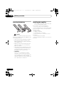 6
6
-
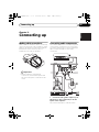 7
7
-
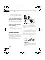 8
8
-
 9
9
-
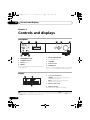 10
10
-
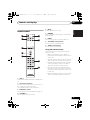 11
11
-
 12
12
-
 13
13
-
 14
14
-
 15
15
-
 16
16
-
 17
17
-
 18
18
-
 19
19
-
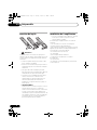 20
20
-
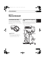 21
21
-
 22
22
-
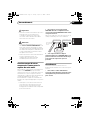 23
23
-
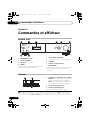 24
24
-
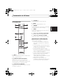 25
25
-
 26
26
-
 27
27
-
 28
28
-
 29
29
-
 30
30
-
 31
31
-
 32
32
-
 33
33
-
 34
34
-
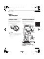 35
35
-
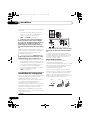 36
36
-
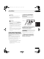 37
37
-
 38
38
-
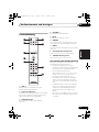 39
39
-
 40
40
-
 41
41
-
 42
42
-
 43
43
-
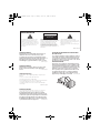 44
44
-
 45
45
-
 46
46
-
 47
47
-
 48
48
-
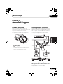 49
49
-
 50
50
-
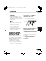 51
51
-
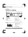 52
52
-
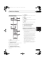 53
53
-
 54
54
-
 55
55
-
 56
56
-
 57
57
-
 58
58
-
 59
59
-
 60
60
-
 61
61
-
 62
62
-
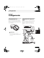 63
63
-
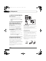 64
64
-
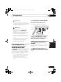 65
65
-
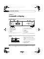 66
66
-
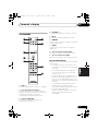 67
67
-
 68
68
-
 69
69
-
 70
70
-
 71
71
-
 72
72
-
 73
73
-
 74
74
-
 75
75
-
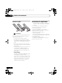 76
76
-
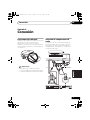 77
77
-
 78
78
-
 79
79
-
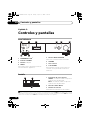 80
80
-
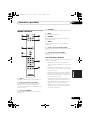 81
81
-
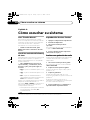 82
82
-
 83
83
-
 84
84
-
 85
85
-
 86
86
-
 87
87
-
 88
88
-
 89
89
-
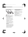 90
90
-
 91
91
-
 92
92
-
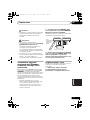 93
93
-
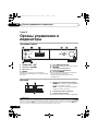 94
94
-
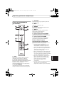 95
95
-
 96
96
-
 97
97
-
 98
98
-
 99
99


BLACK DECKER A-A6-MKII-K-S El manual del propietario
- Categoría
- Amplificadores de audio para automóviles
- Tipo
- El manual del propietario
- Este manual también es adecuado para
en otros idiomas
Otros documentos
-
Pioneer XW-NAS3 Instrucciones de operación
-
Pioneer VSX520D Manual de usuario
-
Pioneer PD-D9MK2-K El manual del propietario
-
Pioneer PD-D6MK2-K El manual del propietario
-
Pioneer VSX-820 El manual del propietario
-
-
-
-
-
Pioneer A-A6-J Manual de usuario