
1
07/28/04 P/N 21273401
Model #
Manufactured & Distributed By:
A Company
Toll-Free Customer Service Number for U.S.: 1-800-558-5234
http://www.huffysports.com
© COPYRIGHT 2004 by HUFFY SPORTS
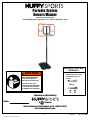
Portable System
Owners Manual
Customer Service Center
• N53 W24700 South Corporate Circle • Sussex, WI 53089 • U.S.A.
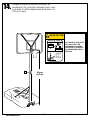
READ AND UNDERSTAND
OPERATOR'S MANUAL
BEFORE USING THIS UNIT.
FAILURE TO FOLLOW
OPERATING INSTRUCTIONS
COULD RESULT IN INJURY
OR DAMAGE TO PROPERTY.
WARNING!
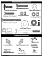
REQUIRED TOOLS AND
MATERIALS:
• (2 each) Wrenches and/or
Socket Wrenches and
Sockets.
1/2" 3/4"
1/2" 3/4"
AND/OR

2
P/N 21273401 07/28/04
Toll-Free Customer Service Number for U.S. : 1-800-558-5234
http://www.huffysports.com
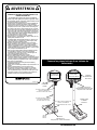
IMPORTANT!
Remove all contents from boxes.
Be sure to check inside pole sections;
hardware and additional parts are packed inside.
NOTICE TO ASSEMBLERS
ALL Huffy Sports basketball Systems, including those used for DISPLAYS, MUST be assembled and
ballasted with sand or water according to instructions. Failure to follow instructions could result in
SERIOUS INJURY. It is NOT acceptable to devise a makeshift weight system.
SAFETY INSTRUCTIONS
FAILURE TO FOLLOW THESE SAFETY INSTRUCTIONS MAY RESULT IN SERIOUS INJURY
AND/OR PROPERTY DAMAGE AND WILL VOID WARRANTY.
Owner must ensure that all players know and follow these rules for safe operation of the system.
To ensure safety, do not attempt to assemble this system without following the instructions carefully. Proper
and complete assembly, use, and supervision is essential for proper operation and to reduce the risk of
accident or injury. A high probability of serious injury exists if this system is not installed, maintained, and
operated properly.
• If using a ladder during assembly, use extreme caution.
• Check base regularly for leakage. Slow leaks could cause the system to tip over
unexpectedly
• Seat the pole sections properly (if applicable). Failure to do so could allow the pole
sections to separate during play and/or during transport of the system.
• Climate, corrosion or misuse could result in system failure.
• If technical assistance is required, contact Huffy Sports.
• Minimum operational height is 6’6” (1.98m) to the bottom of backboard.
Most injuries are caused by misuse and/or not following instructions.
Use caution when using this unit.

07/28/04 P/N 21273401
3
Toll-Free Customer Service Number for U.S. : 1-800-558-5234
http://www.huffysports.com
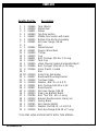
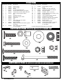
PARTS LIST
ItemQty.Part No. Description
1 1 206646 Tank (Black)
2 1 200628 Wheel Axle
3 2 226401 Wheel
4 1 900060 Top Pole Section
5 1 908057 Middle Pole Section with Label
6 1 900254 Bottom Pole Section Assembly
7 1 203041 Nut, Hex Flange, 3/8-16
8 1 Net
9 1 201342 Wheel Bracket
10 2 201651 Spacer, Wheel Axle
11 1 200929 T-Strap
12 1 206219 Cap
13 1 266001 Bolt, Carriage, 3/8-16 x 1.5 Long
14 1 203617 Tank Cap
15 1 200439 Label, Moving System and Height Adjust.
16 2 203084 Bolt, Carriage, 5/16-18 x 1.75 Long
17 4 201344 Knob, Plastic, 3-sided
18 1 Rim
19 12* 201219 Smart Clip, Net Holder
20 2 900057 Backboard Mounting Bracket
21 1 203124 Tie Down Stake
22 3 203309 Washer, .406 I.D. x 1.0 O.D.
23 2 203231 Bolt, Carriage 5/16-18 x 3-1/2
24 2 200837 Board Spacer
25 4 203100 Nut, Hex Flange, 5/16-18
26 1 900033 Slam Jam Bracket, Black
27 1 203796 Bolt, “Tee” 3/8 - NC x 5 Long
28 1 200318 Bracket Reinforcement, Slam Jam
29 1 203472 Spring, Black
30 1 203795 Nut, Special 3/8-NC
31 1 203470 Washer, Flat 5/8 I.D. x 1-1/2 O.D.
32 4 203104 Bolt, Hex-Flange 5/16-18 x 2" Long
* YOU MAY HAVE EXTRA PARTS WITH THIS MODEL.

4
P/N 21273401 07/28/04
Toll-Free Customer Service Number for U.S. : 1-800-558-5234
http://www.huffysports.com
WARNING
FAILURE TO FOLLOW THESE WARNINGS MAY RESULT
IN SERIOUS INJURY AND/OR PROPERTY DAMAGE.
Owner must ensure that all players know and follow
these rules for safe operation of the system.
• DO NOT HANG on the rim or any part of the system
including backboard, support braces or net.
• During play, especially when performing dunk type
activities, keep player's face away from the backboard, rim
and net. Serious injury could occur if teeth/face come in
contact with backboard, rim or net.
• Do not slide, climb, shake or play on base and/or pole.
• After assembly is complete, fill system completely with
water or sand and stake to the ground. Never leave system
in an upright position without filling base with weight, as
system may tip over causing injuries.
• When adjusting height or moving system, keep hands and
fingers away from moving parts.
• Do not allow children to move or adjust system.
• During play, do not wear jewelry (rings, watches, necklaces,
etc.). Objects may entangle in net.
• Surface beneath the base must be smooth and free of
gravel or other sharp objects. Punctures cause leakage and
could cause system to tip over.
• Keep organic material away from pole base. Grass, litter,
etc. could cause corrosion and/or deterioration.
• Check pole system for signs of corrosion (rust, pitting,
chipping) and repaint with exterior enamel paint. If rust has
penetrated through the steel anywhere, replace pole
immediately.
• Check system before each use for proper ballast, loose
hardware, excessive wear and signs corrosion and repair
before use.
•
Check system before each use for instability.
• Do not use system during windy and/or severe weather
conditions; system may tip over. Place system in the
storage position and/or in an area protected from the wind
and free from personal property and/or overhead wires.
• Never play on damaged equipment.
• See instruction manual for proper installation and
maintenance.
• When moving system, use caution to keep mechanism from
shifting.
• Keep pole top covered with cap at all times.
• Do not allow water in tank to freeze. During sub-freezing
weather add non-toxic antifreeze, sand or empty tank
completely and store. (Do not use salt.)
• Use extreme caution if placing system on sloped surface.
System may tip over more easily.
201241 2/99
In the U.S.:1-800-558-5234 and Canada: 1-800-284-8339

07/28/04 P/N 21273401
5
Toll-Free Customer Service Number for U.S. : 1-800-558-5234
http://www.huffysports.com
PARTS IDENTIFIER- Hardware is actual size
28. Reinforcement Bracket-Qty (1)
17. Knob-Qty (4)
24. Board Spacer-Qty (2)
7. Nut, Hex Flange, 3/8-16-Qty (1)
10. Spacer, Wheel Axle-Qty (2)
16. Bolt, Carriage, 5/16-18 x 1.75 Long-Qty (2)
13. Bolt, Carriage, 3/8-16 x 1.5 Long-Qty (1)
22. Washer, .406 I.D. x 1.0 O.D.-Qty (3)
25. Nut, Hex Flange, 5/16-18-Qty (4)
9. Wheel Bracket-Qty (1)
26. Slam Jam Bracket-Qty (1)
29. Spring-Qty (1)
30. Special Nut-.-Qty (1)
27. "T" Bolt-Qty(1)
20. Backboard Mounting Bracket-Qty (2)
PARTS IDENTIFIER- Not actual size
31. Washer, 5/8 I.D. x 1/2 O.D.-Qty (1)
23. Bolt, Carriage, 5/16-18 x 3.5 Long-Qty (2)
32. Bolt, Hex Flange, 5/16-18 x 2"-Qty (4)

6
P/N 21273401 07/28/04
Toll-Free Customer Service Number for U.S. : 1-800-558-5234
http://www.huffysports.com
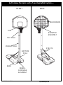
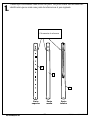
Get to know the basic parts of your basketball system.....
FRONT
TOP POLE
BACK
MIDDLE POLE
RIM
BOTTOM
POLE
STRUTS
ELEVATOR
ASSEMBLY
BACKBOARD
BASE
WHEEL
CARRIAGE
ASSEMBLY

07/28/04 P/N 21273401
7
Toll-Free Customer Service Number for U.S. : 1-800-558-5234
http://www.huffysports.com
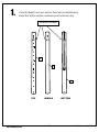
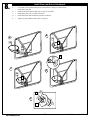
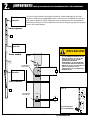
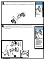
1.
Correctly identify each pole section. Poles have an identification
sticker that will be used as a reference point in the next step.
5
4
6
TOP MIDDLE BOTTOM
Reference Stickers

8
P/N 21273401 07/28/04
Toll-Free Customer Service Number for U.S. : 1-800-558-5234
http://www.huffysports.com
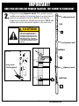
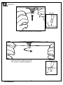
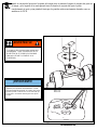
2.
IMPORTANT!
ONCE POLE SECTIONS ARE POUNDED TOGETHER- THEY CANNOT BE TAKEN APART
5
4
6
TOP
MIDDLE
BOTTOM
alignment mark
alignment mark
alignment mark
Align poles using alignment marks. First, pound top and
middle poles together by bouncing them on a scrap piece of
wood on the ground as shown in FIG B. until they no
longer move toward pole identification stickers. THEN add
bottom pole section and pound together in the same way.
middle pole
IDENTIFICATION
STICKER
middle pole
IDENTIFICATION
STICKER
5"
1-1/2"
THE IDENTIFICATION STICKER IS
LOCATED 5" FROM THE END OF
THE POLE. WHEN PROPERLY
POUNDED TOGETHER, THE POLE
SECTIONS SHOULD HAVE A 3-1/2"
MINIMUM OVERLAP, LEAVING 1-
1/2" BETWEEN THE OVERLAPPING
POLE AND THE IDENTIFICATION
STICKER.
CAUTION!
FIG B.
scrap wood
(Not Supplied)

07/28/04 P/N 21273401
9
Toll-Free Customer Service Number for U.S. : 1-800-558-5234
http://www.huffysports.com
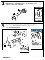
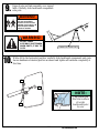
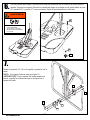
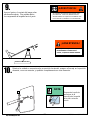
Attach wheel carriage assembly to base (1) with bolt (13), washer (22), and
nut (7) as shown. FINGER TIGHTEN - NO TOOLS REQUIRED. Assembly
will be fully tightened in next step.
3.
4.
9
2
3
10
1
13
7
22
Install wheel axle (2) through wheel bracket (9) and install wheels (3) onto
wheel axle (2) with spacers (10) as shown.
THE SPACER (10) WILL
FIT LOOSELY UNTIL
SECURED INTO THE
CAVITY OF THE BASE.
IMPORTANT!:
BE SURE THAT THE
SQUARE PORTION
OF THE
CARRIAGE BOLT IS
PROPERLY SEATED IN
THE SQUARE CUT-OUT
OF
THE WHEEL BRACKET.
IMPORTANT!:

10
P/N 21273401 07/28/04
Toll-Free Customer Service Number for U.S. : 1-800-558-5234
http://www.huffysports.com
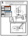
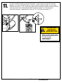
Attach pole assembly to tank assembly as shown. Secure pole assembly to
tank and wheel bracket by turning the pole assembly clockwise as shown.
Tighten pole completely and further rotate pole until struts are aligned
correctly as shown in FIG B.
5.
FIG B
TWO PEOPLE REQUIRED
FOR THIS PROCEDURE.
FAILURE TO FOLLOW THIS
WARNING COULD RESULT IN
SERIOUS INJURY AND/OR
PROPERTY DAMAGE.
WARNING!
IMPORTANT!:
The pole should be turned
approximately 7 complete
rotations to tighten properly.
When properly tightened, the
wheel bracket will be tight
against the base. An assistant is
recommended to hold the base
in place during this step.

07/28/04 P/N 21273401
11
Toll-Free Customer Service Number for U.S. : 1-800-558-5234
http://www.huffysports.com
22
16
17
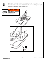
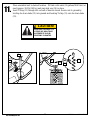
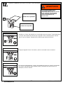
6.
Rotate struts down and bend struts outward to line up with holes on base as
shown. Secure free ends of tank struts to tank with carriage bolt (16), washer (22),
and knob (17) as shown. Repeat for other side.
KNOBS MUST BE TIGHTENED
COMPLETELY AND
CHECKED PERIODICALLY
FOR TIGHTNESS.
WARNING!

12
P/N 21273401 07/28/04
Toll-Free Customer Service Number for U.S. : 1-800-558-5234
http://www.huffysports.com
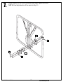
Mount brackets (20 & 26) to backboard and finger tighten as shown.
NOTE: Final adjustments will be made in Step 10.
7.
20
32
24
25
26

07/28/04 P/N 21273401
13
Toll-Free Customer Service Number for U.S. : 1-800-558-5234
http://www.huffysports.com
28
30
31
26
27
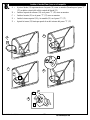
Install Slam Jam Rim to Backboard
18
29
27
31
30
A
B
C
D
E
A • Fit rim (18) securely into bracket (26) as shown (Allow "T"-bolt (27) to slip through
center hole in rim (18).
B • Install reinforcement bracket (28) onto “T” bolt (27) as shown.
C • Install spring (29) onto “T” bolt (27) as shown.
D • Install special nut (30) and washer (31) onto “T” bolt (27).
E • Tighten nut (30) until flush with end of “T” bolt (27).
27
27
8.

14
P/N 21273401 07/28/04
Toll-Free Customer Service Number for U.S. : 1-800-558-5234
http://www.huffysports.com
SAWHORSE OR SUPPORT TABLE
9.
Support pole and tank assembly over support
table. Carefully slide backboard components
onto pole.
TWO PEOPLE REQUIRED
FOR THIS PROCEDURE.
FAILURE TO FOLLOW THIS
WARNING COULD RESULT IN
SERIOUS INJURY AND/OR
PROPERTY DAMAGE.
WARNING!
DO NOT LEAVE
ASSEMBLY UNATTENDED
WHEN EMPTY; IT MAY TIP
OVER.
WARNING!
While still in the horizontal position, carefully slide backboard components onto pole.
Secure hardware at desired position as shown and tighten all hardware completely at
this time.
12
23
17
10.
Peel protective
film from surface
of acrylic
backboard prior
to use.
NOTE:

07/28/04 P/N 21273401
15
Toll-Free Customer Service Number for U.S. : 1-800-558-5234
http://www.huffysports.com
11
14
11
21
21
11
11.
Place assembled unit in desired location. Fill tank with water (26 gallons/98.4 liters) or
sand (approx. 360 lb./163 kg) and snap tank cap (14) in place.
Insert T-strap (11) through slot on back of base as shown. Secure unit to ground by
twisting tie down stake (21) into ground and hooking T-strap (11) onto tie down stake
(21).
ADD TWO GALLONS (7.6
LITERS) OF NON-TOXIC
ANTIFREEZE IN SUB-
FREEZING CLIMATES.
CAUTION!

16
P/N 21273401 07/28/04
Toll-Free Customer Service Number for U.S. : 1-800-558-5234
http://www.huffysports.com
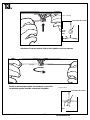
Attach net clips to rim as shown.
CLIP “ARM”
CLIP “BODY”
Insert one “arm” of clip into ram as shown. Twist “body” of clip
slightly so that second “arm” slides over the top of the first “arm” as
shown.
Push in direction indicated by arrows.
Push second “arm” back and into ram as shown.
Twist “body” of clip slightly again to spread “arms” of clip.
Clip “arms” must be flat and touching edge to edge as shown, not
overlapping.
AA
BB
CC
19
19
12.
USE OF THIS PRODUCT
WITHOUT PROPER
INSTALLATION OF SMART
CLIPS
®
, OR WHEN ALL SMART
CLIPS
®
ARE NOT PRESENT
COULD RESULT IN BODILY
HARM. BE SURE TO FOLLOW
DIRECTIONS CAREFULLY.
WARNING!

07/28/04 P/N 21273401
17
Toll-Free Customer Service Number for U.S. : 1-800-558-5234
http://www.huffysports.com
Install net.
Insert net into bottom of clip as shown.
SIDE VIEW
Twist net until it snaps into position.
Net must be centered through clip.
NET
NETCLIP
SIDE VIEW
NET
NETCLIP
13.

18
P/N 21273401 07/28/04
Toll-Free Customer Service Number for U.S. : 1-800-558-5234
http://www.huffysports.com
10 feet
(3.05 m)
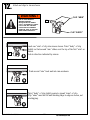
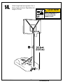
14.
Attach height and moving label (15) to
front of pole as shown. Regulation rim
height is 10 feet.
15
HEIGHT AND MOVING LABEL
MUST NOT OBSTRUCT
FACTORY ATTACHED
WARNING LABEL.
CAUTION!
200439 11/00
1
3
2
MOVING SYSTEM
1. While holding pole, rotate
basketball system forward
until wheels engage with
ground.
2. Move basketball system to
desired location.
3. Carefully rotate basketball
system upright.
4. Reattach ground restraint and
check system for stability.
HEIGHT ADJUSTMENT
A
WARNING
Backboard
may rotate during
height adjustment.
B
WARNING
Do not adjust height of system
in upright position. System must
be in down position to adjust
Rest unit on support table. Remove adjustment knobs (A)
and carriage bolts (B) to extend or retract backboard and rim.
Height adjustment from 7
1/2’ to 10’.

07/28/04 P/N 21273401
19
Toll-Free Customer Service Number for U.S. : 1-800-558-5234
http://www.huffysports.com
ESPAÑOL
Una compañía
Número telefónico gratuito de servicio al cliente en EE. UU.: 1-800-558-5234
http://www.huffysportss.com
Modelo N.º
Sistema portátil
Manual del propietario
Centro de Servicio al Cliente
o N53 W24700 South Corporate Circle o Sussex, WI 53089 o EE.UU.
LEA Y ENTIENDA EL MANUAL
DEL OPERADOR ANTES DE
USAR ESTA UNIDAD.
SI NO SE SIGUEN LAS
INSTRUCCIONES DE
OPERACIÓN SE PODRÍA
OCASIONAR UNA LESIÓN O
DAÑOS A LA PROPIEDAD.OR
DAMAGE TO PROPERTY.
¡Advertencia!
HERRAMIENTAS Y MATERIALES
REQUERIDOS:
• (2 de cada una) llaves de tuercas
y/o llaves de tuercas de boca
tubular y casquillos (se
recomiendan casquillos
profundos).
1/2" 3/4"
1/2"
3/4"
Y/O

20
P/N 21273401 07/28/04
Toll-Free Customer Service Number for U.S. : 1-800-558-5234
http://www.huffysports.com
¡IMPORTANTE!
Saque todo el contenido de las cajas.
Asegúrese de revisar el interior de las secciones del poste.
Ahí se han empacado herraje y piezas adicionales.
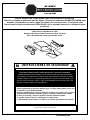
AVISO PARA LAS PERSONAS QUE REALIZAN EL MONTAJE
TODOS los sistemas de baloncesto de Huffy Sports, inclusive los usados para EXHIBICIÓN, DEBEN estar
montados y equilibrados con arena o agua, de acuerdo con las instrucciones. Si se ignoran estas
instrucciones se podría ocasionar una LESIÓN GRAVE. NO es aceptable improvisar un sistema de pesas
provisional.
¡INSTRUCCIONES DE SEGURIDAD!
EL INCUMPLIMIENTO DE ESTAS INSTRUCCIONES DE SEGURIDAD PUEDE DAR COMO
RESULTADO LESIONES GRAVES, DAÑOS MATERIALES Y ANULARÁ LA GARANTÍA..
El propietario debe asegurarse de que todos los jugadores conozcan y obedezcan estas reglas para la operación segura del sistema.
Por su seguridad, no intente montar este sistema sin seguir cuidadosamente las instrucciones. Es esencial
el montaje completo, y el uso y la supervisión adecuados para la operación correcta del sistema y para
reducir el riesgo de accidentes o lesiones. Existe una alta probabilidad de sufrir lesiones graves si este
sistema no se instala, mantiene y opera adecuadamente.
o Si utiliza una escalera de mano durante el montaje, tenga mucho cuidado.
o Revise regularmente la base para detectar fugas. Las fugas lentas podrían causar que
el sistema se cayera inesperadamente
o Asiente correctamente las secciones del poste (si aplica). Si no lo hace, las secciones
del poste podrían separarse durante el juego y/o durante el transporte del sistema.
o El clima, la corrosión y el mal uso podrían ocasionar la falla del sistema.
o Si requiere asistencia técnica, comuníquese con Huffy Sports.
o La altura mínima de operación es de 1.98m (6' 6") hasta la parte inferior del respaldo.
La mayoría de las lesiones son causadas por el uso inadecuado y/o por el incumplimiento de las instrucciones.
Tenga cuidado cuando use esta unidad.

07/28/04 P/N 21273401
21
Toll-Free Customer Service Number for U.S. : 1-800-558-5234
http://www.huffysports.com
LISTA DE PIEZAS
ArtículoCant. Pieza N.º Descripción
1 1 206646 Tanque (negro)
2 1 200628 Eje de la rueda
3 2 226401 Rueda
4 1 900060 Sección superior del poste
5 1 908057 Sección media del poste con etiqueta
6 1 900254 Conjunto de la sección inferior del poste
7 1 203041 Tuerca, brida hexagonal, 3/8-16
8 1 Red
9 1 201342 Soporte de la rueda
10 2 201651 Espaciador, eje de la rueda
11 1 200929 Correa en T
12 1 206219 Tapa
13 1 266001 Perno cabeza de carro, 3/8-16
x 1.5 de longitud
14 1 203617 Tapa del tanque
15 1 200439 Etiqueta, movimiento del sistema y ajuste
de la altura.
16 3 203084 Perno cabeza de carro, 5/16-18
x 1.75 de longitud
ArtículoCant. Pieza N.º Descripción
17 5 201344 Perilla, plástico, 3 lados
18 1 Borde
19 12* 201219 Sujetador de la red, Smart Clip
20 1 900057 Soporte de montaje del respaldo
21 1 203124 Estaca de amarre
22 3 203309 Arandela, .406 D.I. x 1.0 D.E.
23 2 203231 Perno cabeza de carro, 5/16-18 x 3-1/2
24 1 200837 Soporte del borde
25 4 203100 Tuerca, brida hexagonal, 5/16-18
26 1 900033 Soporte Slam Jam, negro
27 1 203796 Perno en "T" 3/8 - NC x 5 de longitud
28 1 200318 Refuerzo de soporte, Slam Jam
29 1 203472 Resorte, negro
30 1 203795 Tuerca, especial 3/8-NC
31 1 203470 Arandela plana, 5/8 D.I. x 1-1/2 D.E.
32
4 203104 Perno, brida hexagonal, 5/16-18
x 2 de longitud
* * Puede haber piezas adicionales en este modelo.
IDENTIFICADOR DE PIEZAS: El herraje aparece en su tamaño real
IDENTIFICADOR DE PIEZAS: Las piezas no aparecen en su tamaño real
#20
#9
#16
#13
#24
#25
#28
#26
#29
#30
#10
#23
#17
#27
#22
#7
#32
#31.

22
P/N 21273401 07/28/04
Toll-Free Customer Service Number for U.S. : 1-800-558-5234
http://www.huffysports.com
SI NO SE OBSERVAN ESTAS ADVERTENCIAS SE
PUEDEN OCASIONAR LESIONES GRAVES Y/O
DAÑOS MATERIALES
El propietario debe asegurarse de que todos los jugadores
onozcan y sigan estas reglas para la operación segura del istema
.
• NO SE CUELGUE del borde ni de ninguna parte del sistema, inclusive
el respaldo, abrazaderas de soporte o red.
• Durante el juego, especialmente cuando se realizan actividades de
disparo de pelota, el jugador debe mantener la cara alejada del
respaldo, borde y red. Si los dientes o la cara entran en contacto con
el respaldo, el borde o la red se podría ocasionar una lesión grave.
• No se deslice, suba, mueva ni juegue sobre la base y/o en el poste.
• Después de terminar el montaje, llene completamente el sistema con
agua o arena y fíjelo al piso. Nunca deje el sistema en una posición
vertical con la base vacía, ya que se podría ladear y causar lesiones.
• Cuando ajuste la altura o mueva el sistema, mantenga las manos y
los dedos alejados de las partes movibles.
• No permita que los niños muevan o ajusten el sistema.
• Durante el juego no use bisutería (anillos, relojes, collares, etc.) Los
objetos pueden enredarse en la red.
• La superficie debajo de la base debe estar lisa y no tener grava ni
otros objetos filosos. Las perforaciones ocasionan fugas y éstas
podrían ocasionar que el sistema se ladee.
• Mantenga el material orgánico alejado de la base del poste. El
césped, desperdicios, etc. podrían causar corrosión y/o deterioro.
• Verifique que el sistema del poste no esté corroído (oxidación,
corrosión, astillamiento) y si es así vuélvalo a pintar con pintura de
esmalte para exteriores. Si la oxidación penetró en el acero en algún
punto, reemplace inmediatamente el poste.
• Antes de usar el sistema verifique que tenga el balasto adecuado,
que la tornillería no esté floja y que no esté excesivamente
desgastado ni tenga signos de corrosión. Si presenta alguna de
estas condiciones repárelo antes de usarlo.
• Revise la estabilidad del sistema antes de usarlo.
• No use el sistema durante condiciones de mucho viento y/o
condiciones climáticas severas, el sistema se puede ladear. Coloque
el sistema en posición de almacenamiento y/o en un área protegida
del viento y alejado de la propiedad personal o cables suspendidos.
• Nunca juegue en equipo dañado.
• Consulte el manual de instrucciones para ver la instalación y
mantenimiento adecuados.
• Cuando mueva el sistema tenga cuidado de que el mecanismo no se
desplace.
• Siempre mantenga tapada la sección superior del poste.
• No permita que el agua del tanque se congele. En condiciones
climáticas bajo cero añada un anticongelante no tóxico, arena, o
vacíe completamente el tanque y almacene el sistema. (No use sal.)
• Tenga mucho cuidado si coloca el sistema en una superficie con
pendiente. El sistema se puede ladear más fácilmente.
ADVERTENCIA
201241 2/99
CONTREFICHES
STREBEN
PUNTALES
SYSTÈME ÉLÉVATEUR
VERLÄNGERUNGSBAUGRUPPE
CONJUNTO DEL ELEVADOR
PANNEAU
KORBWAND
RESPALDO
Conozca las piezas básicas de su sistema de
baloncesto…
ARRIÈRE
RÜCKSEITE
PARTE POSTERIOR
SECTION DE POTEAU SUPÉRIEURE
OBERES STANGENTEIL
SECCIÓN SUPERIOR DEL POSTE
SECTION DE POTEAU CENTRALE
MITTLERES STANGENTEIL
SECCIÓN MEDIA DEL POSTE
CERCEAU
KORBRAND
BORDE
SECTION DE POTEAU INFÉRIEURE
UNTERES STANGENTEIL
SECCIÓN INFERIOR DEL POSTE
SOCLE
BASE
BASE
CHARIOT
RÄDERGRUPPE
CONJUNTO DEL CARRO PORTAMUELA
AVANT
VORDERSEITE
PARTE FRONTAL

07/28/04 P/N 21273401
23
Toll-Free Customer Service Number for U.S. : 1-800-558-5234
http://www.huffysports.com
1.
• Identifique correctamente cada sección del poste. Los postes tienen una calcomanía de
identificación que se usará como punto de referencia en el paso siguiente.
5
4
6
Parte
superior
Parte
media
Parte
inferior
Calcomanías de referencia

24
P/N 21273401 07/28/04
Toll-Free Customer Service Number for U.S. : 1-800-558-5234
http://www.huffysports.com
¡IMPORTANTE! UNA VEZ QUE LAS SECCIONES DEL POSTE SE HAN EMBRAGADO ENTRE SÍ, YA NO SE PODRÁN SEPARAR
5
4
Parte superior
Parte media
Parte inferior
Marca de
alineación.
Marca de
alineación.
Marca de
alineación.
• Alinee los postes usando las marcas de alineación. Primero embrague las secciones
superior y media del poste golpeándolas entre sí sobre un trozo de madera colocado en el
piso como se muestra en la FIG. B hasta que ya no se muevan hacia las calcomanías de
identificación del poste. LUEGO añada la sección inferior del poste y golpee las secciones
entre sí de la misma manera.
FIG. B
Trozo de madera
(No se suministra)
middle pole
CALCOMANÍAS DE
IDENTIFICACIÓN
middle pole
CALCOMANÍAS DE
IDENTIFICACIÓN
5"
1-1/2"
2.
Marca de alineación.
6
Orificio.
LA CALCOMANÍA DE IDENTIFICACIÓN
ESTÁ COLOCADA A 12.7 CM (5") DEL
EXTREMO DEL POSTE. CUANDO
ESTÁN ADECUADAMENTE
EMBRAGADAS, LAS SECCIONES DEL
POSTE DEBEN TENER UN TRASLAPE
MÍNIMO DE 9 CM (3 1/2"), DEJANDO 3.8
CM (1 1/2") ENTRE EL POSTE
TRASLAPADO Y LA CALCOMANÍA DE
IDENTIFICACIÓN.
¡PRECAUCIÓN!

07/28/04 P/N 21273401
25
Toll-Free Customer Service Number for U.S. : 1-800-558-5234
http://www.huffysports.com
3.
4.
• Instale el eje de la rueda (2) a través del carro portamuela (9) e instale las
ruedas (3) en el eje de la rueda (2) con los espaciadores (10) como se muestra.
9
2
3
10
Conecte el conjunto del carro portamuela a la base (1) con el perno (13), la
arandela (22) y la tuerca (7) como se muestra. APRIETE CON LOS DEDOS, NO
SE REQUIEREN HERRAMIENTAS. El conjunto se apretará completamente en
el siguiente paso.
EL ESPACIADOR (1)) SE
AJUSTARÁ
HOLGADAMENTE HASTA
QUE SE FIJE EN LA
CAVIDAD DE LA BASE
¡IMPORTANTE!
CONECTE EL CONJUNTO
DEL CARRO
PORTAMUELA A LA BASE
(1) CON EL PERNO (13),
LA ARANDELA (22) Y LA
TUERCA (7) COMO SE
MUESTRA. APRIETE CON
LOS DEDOS, NO SE
REQUIEREN
HERRAMIENTAS. EL
CONJUNTO SE
APRETARÁ
COMPLETAMENTE EN EL
SIGUIENTE PASO.
¡IMPORTANTE!
1
13
7
22

26
P/N 21273401 07/28/04
Toll-Free Customer Service Number for U.S. : 1-800-558-5234
http://www.huffysports.com
Instale el conjunto del poste en el conjunto del tanque como se muestra. Asegure el conjunto del poste en
el tanque y en el soporte de la rueda girando hacia la derecha el conjunto del poste. Apriete
completamente el poste y siga girándolo hasta que los puntales estén correctamente alineados como se
muestra en la FIG B.
5.
FIG B
El poste se debe girar aproximadamente 7 vueltas
completas para apretarlo adecuadamente. Cuando
esté adecuadamente apretado, el soporte de la rueda
quedará ajustado contra la base. Se recomienda que
en este paso un asistente mantenga la base fija en
su lugar.
¡IMPORTANTE!
Se requieren dos personas para realizar este
procedimiento. SI NO SE OBSERVA ESTA
ADVERTENCIA SE PODRÍA OCASIONAR
UNA lesión GRAVE Y/O DAÑOS A LA
PROPIEDAD.
¡ADVERTENCIA!

07/28/04 P/N 21273401
27
Toll-Free Customer Service Number for U.S. : 1-800-558-5234
http://www.huffysports.com
7.
20
32
24
6.
Gire los puntales hacia abajo y dóblelos hacia fuera para alinearlos con los orificios de la base como se
muestra. Asegure los extremos libres de los puntales del tanque el en tanque con el perno cabeza de carro
(16), arandela (22) y perilla (17) como se muestra. Repita el procedimiento en el otro lado.
LAS PERILLAS DEBEN ESTAR
COMPLETAMENTE
APRETADAS Y SE DEBE
REVISAR PERIÓDICAMENTE
SU AJUSTE.
¡ADVERTENCIA!
22
16
17
Monte los soportes (20, 26) en el respaldo y apriételos con la
mano.
NOTA: Los ajustes finales se harán en el paso 10.
¡IMPORTANTE! Para el montaje del borde cargado con
resorte, consulte las instrucciones que se incluyen con el
herraje del borde.
25
26

28
P/N 21273401 07/28/04
Toll-Free Customer Service Number for U.S. : 1-800-558-5234
http://www.huffysports.com
Instale el borde Slam Jam en el respaldo
A • Ajuste el borde (18) seguramente en el soporte (26) como se muestra (Permita que el perno "T"
(27) se deslice a través del orificio central del borde (32).
B • Instale el soporte de refuerzo (28) en el perno "T" (42) como se muestra.
C • Instale el resorte (29) en el perno "T" (27) como se muestra.
D • Instale la tuerca especial (30) y la arandela (31) en el perno "T" (27).
E • Apriete la tuerca (30) hasta que quede al ras del extremo del perno "T" (27)
8.
28
30
31
26
27
18
29
27
31
30
A
B
C
D
E
27
27

07/28/04 P/N 21273401
29
Toll-Free Customer Service Number for U.S. : 1-800-558-5234
http://www.huffysports.com
9.
SAWHORSE OR SUPPORT TABLE
¡ADVERTENCIA!
Se requieren dos personas para realizar este
procedimiento. SI NO SE OBSERVA ESTA
ADVERTENCIA SE PODRÍA OCASIONAR UNA
lesión GRAVE Y/O DAÑOS A LA PROPIEDAD.
¡ADVERTENCIA!
NO DEJE EL CONJUNTO
DESATENDIDO CUANDO ESTÉ
VACÍO, YA QUE SE PUEDE LADEAR.
12
23
17
10.
Mientras la unidad se encuentre aún en posición horizontal, asegure el herraje en la posición
deseada, como se muestra, y apriételo completamente en este momento.
NOTA:
Desprenda la película
protectora de la
superficie del respaldo
de acrílico antes de
usarlo.
Apoye el poste y el conjunto del tanque sobre
una mesa de soporte. Con cuidado deslice
los componentes del respaldo hacia el poste.

30
P/N 21273401 07/28/04
Toll-Free Customer Service Number for U.S. : 1-800-558-5234
http://www.huffysports.com
11
14
11
21
21
11
11.
Coloque la unidad montada en la ubicación deseada. Llene el tanque con agua (98.4 litros/26
galones) o con arena (163 kg/360 libras) y conecte a presión la tapa del tanque (14) en su lugar.
Introduzca la correa en T (11) a través de la ranura que se encuentra en la parte posterior de la base,
como se muestra. Fije la unidad introduciendo la estaca de amarre (21) en el piso con un
movimiento rotatorio y enganchando la correa en T (11) en la estaca de amarre (21).
AÑADA 7.6 LITROS (DOS GALONES)
DE ANTICONGELANTE NO TÓXICO SI
EL CLIMA ALCANZA
TEMPERATURAS DE
CONGELAMIENTO.
ATTENTION !
VORSICHT!
¡PRECAUCIÓN!

07/28/04 P/N 21273401
31
Toll-Free Customer Service Number for U.S. : 1-800-558-5234
http://www.huffysports.com
Instale los sujetadores de la red en el borde, como se muestra.
Introduzca un "brazo" del sujetador en el accionador como se muestra. Tuerza ligeramente
el "cuerpo" del sujetador de manera que el segundo "brazo" se deslice sobre el primer
"brazo" como se muestra. Empuje hacia la dirección que indican las flechas.
Empuje el segundo "brazo" hacia atrás y hacia el accionador como se muestra.
Otra vez tuerza ligeramente el "cuerpo" del sujetador para abrir los "brazos" del sujetador.
Los "brazos" del sujetador deben quedar planos y tocándose de borde a borde, sin
traslaparse, como se muestra.
AA
BB
CC
19
19
12.
"BRAZO" DEL SUJETADOR
"CUERPO" DEL SUJETADOR
EL USO DE ESTE PRODUCTO SIN LA
INSTALACIÓN ADECUADA DE LOS
SUJETADORES SMART CLIP®, O LA FALTA DE
ELLOS PUEDE DAR COMO RESULTADO
DAÑOS CORPORALES. ASEGÚRESE DE
SEGUIR CUIDADOSAMENTE LAS
INSTRUCCIONES.
¡ADVERTENCIA!

32
P/N 21273401 07/28/04
Toll-Free Customer Service Number for U.S. : 1-800-558-5234
http://www.huffysports.com
Instale la red.
Introduzca la red en la parte inferior del sujetador como se muestra.
Tuerza la red hasta que quede conectada en su posición.
La red debe quedar centrada a través del sujetador.
RED
SUJETADOR DE LA RED
13.
VISTA LATERAL
SUJETADOR DE LA RED
FILET
NETZ
RED
VISTA LATERAL

07/28/04 P/N 21273401
33
Toll-Free Customer Service Number for U.S. : 1-800-558-5234
http://www.huffysports.com
10 pies
(3.05 m)
14.
Aplique la etiqueta de ajuste de la altura y de
movimiento (15) en la parte frontal del poste, como
se muestra. La altura reglamentaria del borde es de
3.05 m (10 pies).
15
LA ETIQUETA DE AJUSTE
DE LA ALTURA Y DE
MOVIMIENTO NO DEBE
OBSTRUIR LA ETIQUETA
DE ADVERTENCIA DE LA
FÁBRICA.
¡PRECAUCIÓN!
200439 11/00
1
3
2
MOVING SYSTEM
1. While holding pole, rotate
basketball system forward
until wheels engage with
ground.
2. Move basketball system to
desired location.
3. Carefully rotate basketball
system upright.
4. Reattach ground restraint and
check system for stability.
HEIGHT ADJUSTMENT
A
WARNING
Backboard
may rotate during
height adjustment.
B
WARNING
Do not adjust height of system
in upright position. System must
be in down position to adjust
Rest unit on support table. Remove adjustment knobs (A)
and carriage bolts (B) to extend or retract backboard and rim.
Height adjustment from 7
1/2’ to 10’.
Transcripción de documentos
Portable System Owners Manual Customer Service Center • N53 W24700 South Corporate Circle • Sussex, WI 53089 • U.S.A. REQUIRED TOOLS AND MATERIALS: WARNING! • (2 each) Wrenches and/or Socket Wrenches and Sockets. READ AND UNDERSTAND OPERATOR'S MANUAL BEFORE USING THIS UNIT. 1/2" FAILURE TO FOLLOW OPERATING INSTRUCTIONS COULD RESULT IN INJURY OR DAMAGE TO PROPERTY. 3/4" AND/OR 1/2" 3/4" Manufactured & Distributed By: Model # A Company Toll-Free Customer Service Number for U.S.: 1-800-558-5234 http://www.huffysports.com 1 © COPYRIGHT 2004 by HUFFY SPORTS 07/28/04 P/N 21273401 NOTICE TO ASSEMBLERS ALL Huffy Sports basketball Systems, including those used for DISPLAYS, MUST be assembled and ballasted with sand or water according to instructions. Failure to follow instructions could result in SERIOUS INJURY. It is NOT acceptable to devise a makeshift weight system. SAFETY INSTRUCTIONS FAILURE TO FOLLOW THESE SAFETY INSTRUCTIONS MAY RESULT IN SERIOUS INJURY AND/OR PROPERTY DAMAGE AND WILL VOID WARRANTY. Owner must ensure that all players know and follow these rules for safe operation of the system. To ensure safety, do not attempt to assemble this system without following the instructions carefully. Proper and complete assembly, use, and supervision is essential for proper operation and to reduce the risk of accident or injury. A high probability of serious injury exists if this system is not installed, maintained, and operated properly. • If using a ladder during assembly, use extreme caution. • Check base regularly for leakage. Slow leaks could cause the system to tip over unexpectedly • Seat the pole sections properly (if applicable). Failure to do so could allow the pole sections to separate during play and/or during transport of the system. • Climate, corrosion or misuse could result in system failure. • If technical assistance is required, contact Huffy Sports. • Minimum operational height is 6’6” (1.98m) to the bottom of backboard. Most injuries are caused by misuse and/or not following instructions. Use caution when using this unit. IMPORTANT! Remove all contents from boxes. Be sure to check inside pole sections; hardware and additional parts are packed inside. P/N 21273401 07/28/04 2 Toll-Free Customer Service Number for U.S. : 1-800-558-5234 http://www.huffysports.com PARTS LIST ItemQty.Part No. 1 1 206646 2 1 200628 3 2 226401 4 1 900060 5 1 908057 6 1 900254 7 1 203041 8 1 9 1 201342 10 2 201651 11 1 200929 12 1 206219 13 1 266001 14 1 203617 15 1 200439 16 2 203084 17 4 201344 18 1 19 12* 201219 20 2 900057 21 1 203124 22 3 203309 23 2 203231 24 2 200837 25 4 203100 26 1 900033 27 1 203796 28 1 200318 29 1 203472 30 1 203795 31 1 203470 32 4 203104 Description Tank (Black) Wheel Axle Wheel Top Pole Section Middle Pole Section with Label Bottom Pole Section Assembly Nut, Hex Flange, 3/8-16 Net Wheel Bracket Spacer, Wheel Axle T-Strap Cap Bolt, Carriage, 3/8-16 x 1.5 Long Tank Cap Label, Moving System and Height Adjust. Bolt, Carriage, 5/16-18 x 1.75 Long Knob, Plastic, 3-sided Rim Smart Clip, Net Holder Backboard Mounting Bracket Tie Down Stake Washer, .406 I.D. x 1.0 O.D. Bolt, Carriage 5/16-18 x 3-1/2 Board Spacer Nut, Hex Flange, 5/16-18 Slam Jam Bracket, Black Bolt, “Tee” 3/8 - NC x 5 Long Bracket Reinforcement, Slam Jam Spring, Black Nut, Special 3/8-NC Washer, Flat 5/8 I.D. x 1-1/2 O.D. Bolt, Hex-Flange 5/16-18 x 2" Long * YOU MAY HAVE EXTRA PARTS WITH THIS MODEL. Toll-Free Customer Service Number for U.S. : 1-800-558-5234 http://www.huffysports.com 3 07/28/04 P/N 21273401 WARNING FAILURE TO FOLLOW THESE WARNINGS MAY RESULT IN SERIOUS INJURY AND/OR PROPERTY DAMAGE. Owner must ensure that all players know and follow these rules for safe operation of the system. • DO NOT HANG on the rim or any part of the system including backboard, support braces or net. • During play, especially when performing dunk type activities, keep player's face away from the backboard, rim and net. Serious injury could occur if teeth/face come in contact with backboard, rim or net. • Do not slide, climb, shake or play on base and/or pole. • After assembly is complete, fill system completely with water or sand and stake to the ground. Never leave system in an upright position without filling base with weight, as system may tip over causing injuries. • When adjusting height or moving system, keep hands and fingers away from moving parts. • Do not allow children to move or adjust system. • During play, do not wear jewelry (rings, watches, necklaces, etc.). Objects may entangle in net. • Surface beneath the base must be smooth and free of gravel or other sharp objects. Punctures cause leakage and could cause system to tip over. • Keep organic material away from pole base. Grass, litter, etc. could cause corrosion and/or deterioration. • Check pole system for signs of corrosion (rust, pitting, chipping) and repaint with exterior enamel paint. If rust has penetrated through the steel anywhere, replace pole immediately. • Check system before each use for proper ballast, loose hardware, excessive wear and signs corrosion and repair before use. • Check system before each use for instability. • Do not use system during windy and/or severe weather conditions; system may tip over. Place system in the storage position and/or in an area protected from the wind and free from personal property and/or overhead wires. • Never play on damaged equipment. • See instruction manual for proper installation and maintenance. • When moving system, use caution to keep mechanism from shifting. • Keep pole top covered with cap at all times. • Do not allow water in tank to freeze. During sub-freezing weather add non-toxic antifreeze, sand or empty tank completely and store. (Do not use salt.) • Use extreme caution if placing system on sloped surface. System may tip over more easily. In the U.S.:1-800-558-5234 and Canada: 1-800-284-8339 201241 P/N 21273401 07/28/04 4 2/99 Toll-Free Customer Service Number for U.S. : 1-800-558-5234 http://www.huffysports.com PARTS IDENTIFIER- Hardware is actual size 32. Bolt, Hex Flange, 5/16-18 x 2"-Qty (4) 13. Bolt, Carriage, 3/8-16 x 1.5 Long-Qty (1) 16. Bolt, Carriage, 5/16-18 x 1.75 Long-Qty (2) 22. Washer, .406 I.D. x 1.0 O.D.-Qty (3) 25. Nut, Hex Flange, 5/16-18-Qty (4) 7. Nut, Hex Flange, 3/8-16-Qty (1) 23. Bolt, Carriage, 5/16-18 x 3.5 Long-Qty (2) 10. Spacer, Wheel Axle-Qty (2) 31. Washer, 5/8 I.D. x 1/2 O.D.-Qty (1) 30. Special Nut-.-Qty (1) 27. "T" Bolt-Qty(1) PARTS IDENTIFIER- Not actual size 9. Wheel Bracket-Qty (1) 26. Slam Jam Bracket-Qty (1) 20. Backboard Mounting Bracket-Qty (2) 29. Spring-Qty (1) 28. Reinforcement Bracket-Qty (1) 24. Board Spacer-Qty (2) Toll-Free Customer Service Number for U.S. : 1-800-558-5234 http://www.huffysports.com 5 17. Knob-Qty (4) 07/28/04 P/N 21273401 Get to know the basic parts of your basketball system..... FRONT BACK BACKBOARD RIM ELEVATOR ASSEMBLY TOP POLE MIDDLE POLE STRUTS BOTTOM POLE BASE WHEEL CARRIAGE ASSEMBLY P/N 21273401 07/28/04 6 Toll-Free Customer Service Number for U.S. : 1-800-558-5234 http://www.huffysports.com 1. Correctly identify each pole section. Poles have an identification sticker that will be used as a reference point in the next step. Reference Stickers 4 5 6 TOP Toll-Free Customer Service Number for U.S. : 1-800-558-5234 http://www.huffysports.com MIDDLE 7 BOTTOM 07/28/04 P/N 21273401 IMPORTANT! ONCE POLE SECTIONS ARE POUNDED TOGETHER- THEY CANNOT BE TAKEN APART 2. Align poles using alignment marks. First, pound top and middle poles together by bouncing them on a scrap piece of wood on the ground as shown in FIG B. until they no longer move toward pole identification stickers. THEN add bottom pole section and pound together in the same way. alignment mark TOP CAUTION! 4 THE IDENTIFICATION STICKER IS LOCATED 5" FROM THE END OF THE POLE. WHEN PROPERLY POUNDED TOGETHER, THE POLE SECTIONS SHOULD HAVE A 3-1/2" MINIMUM OVERLAP, LEAVING 11/2" BETWEEN THE OVERLAPPING POLE AND THE IDENTIFICATION STICKER. alignment mark MIDDLE FIG B. 5 5" IDENTIFICATION STICKER middle pole scrap wood (Not Supplied) alignment mark IDENTIFICATION STICKER 1-1/2" BOTTOM middle pole 6 P/N 21273401 07/28/04 8 Toll-Free Customer Service Number for U.S. : 1-800-558-5234 http://www.huffysports.com 3. Install wheel axle (2) through wheel bracket (9) and install wheels (3) onto wheel axle (2) with spacers (10) as shown. IMPORTANT!: 9 2 3 10 THE SPACER (10) WILL FIT LOOSELY UNTIL SECURED INTO THE CAVITY OF THE BASE. 4. Attach wheel carriage assembly to base (1) with bolt (13), washer (22), and nut (7) as shown. FINGER TIGHTEN - NO TOOLS REQUIRED. Assembly will be fully tightened in next step. IMPORTANT!: 7 22 BE SURE THAT THE SQUARE PORTION OF THE CARRIAGE BOLT IS PROPERLY SEATED IN THE SQUARE CUT-OUT OF THE WHEEL BRACKET. 1 13 Toll-Free Customer Service Number for U.S. : 1-800-558-5234 http://www.huffysports.com 9 07/28/04 P/N 21273401 5. Attach pole assembly to tank assembly as shown. Secure pole assembly to tank and wheel bracket by turning the pole assembly clockwise as shown. Tighten pole completely and further rotate pole until struts are aligned correctly as shown in FIG B. WARNING! TWO PEOPLE REQUIRED FOR THIS PROCEDURE. FAILURE TO FOLLOW THIS WARNING COULD RESULT IN SERIOUS INJURY AND/OR PROPERTY DAMAGE. IMPORTANT!: The pole should be turned approximately 7 complete rotations to tighten properly. When properly tightened, the wheel bracket will be tight against the base. An assistant is recommended to hold the base in place during this step. FIG B P/N 21273401 07/28/04 10 Toll-Free Customer Service Number for U.S. : 1-800-558-5234 http://www.huffysports.com 6. Rotate struts down and bend struts outward to line up with holes on base as shown. Secure free ends of tank struts to tank with carriage bolt (16), washer (22), and knob (17) as shown. Repeat for other side. WARNING! KNOBS MUST BE TIGHTENED COMPLETELY AND CHECKED PERIODICALLY FOR TIGHTNESS. 16 22 17 Toll-Free Customer Service Number for U.S. : 1-800-558-5234 http://www.huffysports.com 11 07/28/04 P/N 21273401 7. Mount brackets (20 & 26) to backboard and finger tighten as shown. NOTE: Final adjustments will be made in Step 10. 26 32 25 24 20 P/N 21273401 07/28/04 12 Toll-Free Customer Service Number for U.S. : 1-800-558-5234 http://www.huffysports.com 8. Install Slam Jam Rim to Backboard A • B • Fit rim (18) securely into bracket (26) as shown (Allow "T"-bolt (27) to slip through center hole in rim (18). Install reinforcement bracket (28) onto “T” bolt (27) as shown. C • Install spring (29) onto “T” bolt (27) as shown. D • Install special nut (30) and washer (31) onto “T” bolt (27). E • Tighten nut (30) until flush with end of “T” bolt (27). B A 28 18 27 27 26 30 C 31 D 29 27 27 31 E 30 Toll-Free Customer Service Number for U.S. : 1-800-558-5234 http://www.huffysports.com 13 07/28/04 P/N 21273401 9. Support pole and tank assembly over support table. Carefully slide backboard components onto pole. WARNING! TWO PEOPLE REQUIRED FOR THIS PROCEDURE. FAILURE TO FOLLOW THIS WARNING COULD RESULT IN SERIOUS INJURY AND/OR PROPERTY DAMAGE. WARNING! DO NOT LEAVE ASSEMBLY UNATTENDED WHEN EMPTY; IT MAY TIP OVER. 10. SAWHORSE OR SUPPORT TABLE While still in the horizontal position, carefully slide backboard components onto pole. Secure hardware at desired position as shown and tighten all hardware completely at this time. 17 12 NOTE: Peel protective film from surface of acrylic backboard prior to use. 23 P/N 21273401 07/28/04 14 Toll-Free Customer Service Number for U.S. : 1-800-558-5234 http://www.huffysports.com 11. Place assembled unit in desired location. Fill tank with water (26 gallons/98.4 liters) or sand (approx. 360 lb./163 kg) and snap tank cap (14) in place. Insert T-strap (11) through slot on back of base as shown. Secure unit to ground by twisting tie down stake (21) into ground and hooking T-strap (11) onto tie down stake (21). CAUTION! ADD TWO GALLONS (7.6 LITERS) OF NON-TOXIC ANTIFREEZE IN SUBFREEZING CLIMATES. 11 Toll-Free Customer Service Number for U.S. : 1-800-558-5234 http://www.huffysports.com 21 11 14 21 15 11 07/28/04 P/N 21273401 12. Attach net clips to rim as shown. WARNING! CLIP “ARM” USE OF THIS PRODUCT WITHOUT PROPER INSTALLATION OF SMART CLIPS®, OR WHEN ALL SMART CLIPS® ARE NOT PRESENT COULD RESULT IN BODILY HARM. BE SURE TO FOLLOW DIRECTIONS CAREFULLY. 19 A 19 CLIP “BODY” Insert one “arm” of clip into ram as shown. Twist “body” of clip slightly so that second “arm” slides over the top of the first “arm” as shown. Push in direction indicated by arrows. Push second “arm” back and into ram as shown. B Twist “body” of clip slightly again to spread “arms” of clip. Clip “arms” must be flat and touching edge to edge as shown, not overlapping. C P/N 21273401 07/28/04 16 Toll-Free Customer Service Number for U.S. : 1-800-558-5234 http://www.huffysports.com 13. Install net. SIDE VIEW NETCLIP NET Insert net into bottom of clip as shown. SIDE VIEW Twist net until it snaps into position. Net must be centered through clip. NETCLIP NET Toll-Free Customer Service Number for U.S. : 1-800-558-5234 http://www.huffysports.com 17 07/28/04 P/N 21273401 14. Attach height and moving label (15) to front of pole as shown. Regulation rim height is 10 feet. HEIGHT ADJUSTMENT Rest unit on support table. Remove adjustment knobs (A) and carriage bolts (B) to extend or retract backboard and rim. Height adjustment from 7 1/2’ to 10’. A WARNING Backboard may rotate during height adjustment. CAUTION! B WARNING Do not adjust height of system in upright position. System must be in down position to adjust MOVING SYSTEM 1. While holding pole, rotate basketball system forward until wheels engage with ground. 2. Move basketball system to desired location. 1 2 3 3. Carefully rotate basketball system upright. 4. Reattach ground restraint and check system for stability. 200439 15 P/N 21273401 07/28/04 11/00 HEIGHT AND MOVING LABEL MUST NOT OBSTRUCT FACTORY ATTACHED WARNING LABEL. 10 feet (3.05 m) 18 Toll-Free Customer Service Number for U.S. : 1-800-558-5234 http://www.huffysports.com ESPAÑOL Sistema portátil Manual del propietario Centro de Servicio al Cliente o N53 W24700 South Corporate Circle o Sussex, WI 53089 o EE.UU. HERRAMIENTAS Y MATERIALES REQUERIDOS: ¡Advertencia! • (2 de cada una) llaves de tuercas y/o llaves de tuercas de boca tubular y casquillos (se recomiendan casquillos profundos). LEA Y ENTIENDA EL MANUAL DEL OPERADOR ANTES DE USAR ESTA UNIDAD. SI NO SE SIGUEN LAS INSTRUCCIONES DE OPERACIÓN SE PODRÍA OCASIONAR UNA LESIÓN O DAÑOS A LA PROPIEDAD.OR DAMAGE TO PROPERTY. 1/2" Y/O 1/2" Modelo N.º 3/4" 3/4" Una compañía Número telefónico gratuito de servicio al cliente en EE. UU.: 1-800-558-5234 http://www.huffysportss.com Toll-Free Customer Service Number for U.S. : 1-800-558-5234 http://www.huffysports.com 19 07/28/04 P/N 21273401 AVISO PARA LAS PERSONAS QUE REALIZAN EL MONTAJE TODOS los sistemas de baloncesto de Huffy Sports, inclusive los usados para EXHIBICIÓN, DEBEN estar montados y equilibrados con arena o agua, de acuerdo con las instrucciones. Si se ignoran estas instrucciones se podría ocasionar una LESIÓN GRAVE. NO es aceptable improvisar un sistema de pesas provisional. ¡IMPORTANTE! Saque todo el contenido de las cajas. Asegúrese de revisar el interior de las secciones del poste. Ahí se han empacado herraje y piezas adicionales. ¡INSTRUCCIONES DE SEGURIDAD! EL INCUMPLIMIENTO DE ESTAS INSTRUCCIONES DE SEGURIDAD PUEDE DAR COMO RESULTADO LESIONES GRAVES, DAÑOS MATERIALES Y ANULARÁ LA GARANTÍA.. El propietario debe asegurarse de que todos los jugadores conozcan y obedezcan estas reglas para la operación segura del sistema. Por su seguridad, no intente montar este sistema sin seguir cuidadosamente las instrucciones. Es esencial el montaje completo, y el uso y la supervisión adecuados para la operación correcta del sistema y para reducir el riesgo de accidentes o lesiones. Existe una alta probabilidad de sufrir lesiones graves si este sistema no se instala, mantiene y opera adecuadamente. o Si utiliza una escalera de mano durante el montaje, tenga mucho cuidado. o Revise regularmente la base para detectar fugas. Las fugas lentas podrían causar que el sistema se cayera inesperadamente o Asiente correctamente las secciones del poste (si aplica). Si no lo hace, las secciones del poste podrían separarse durante el juego y/o durante el transporte del sistema. o El clima, la corrosión y el mal uso podrían ocasionar la falla del sistema. o Si requiere asistencia técnica, comuníquese con Huffy Sports. o La altura mínima de operación es de 1.98m (6' 6") hasta la parte inferior del respaldo. La mayoría de las lesiones son causadas por el uso inadecuado y/o por el incumplimiento de las instrucciones. Tenga cuidado cuando use esta unidad. P/N 21273401 07/28/04 20 Toll-Free Customer Service Number for U.S. : 1-800-558-5234 http://www.huffysports.com LISTA DE PIEZAS ArtículoCant. Pieza N.º 1 2 3 4 5 6 7 8 9 10 11 12 13 1 1 2 1 1 1 1 1 1 2 1 1 1 206646 200628 226401 900060 908057 900254 203041 201342 201651 200929 206219 266001 14 15 1 1 203617 200439 16 3 203084 Descripción ArtículoCant. Pieza N.º Tanque (negro) Eje de la rueda Rueda Sección superior del poste Sección media del poste con etiqueta Conjunto de la sección inferior del poste Tuerca, brida hexagonal, 3/8-16 Red Soporte de la rueda Espaciador, eje de la rueda Correa en T Tapa Perno cabeza de carro, 3/8-16 x 1.5 de longitud Tapa del tanque Etiqueta, movimiento del sistema y ajuste de la altura. Perno cabeza de carro, 5/16-18 x 1.75 de longitud 17 18 19 20 21 22 23 24 25 26 27 28 29 30 31 32 5 1 12* 1 1 3 2 1 4 1 1 1 1 1 1 201344 201219 900057 203124 203309 203231 200837 203100 900033 203796 200318 203472 203795 203470 4 203104 Descripción Perilla, plástico, 3 lados Borde Sujetador de la red, Smart Clip Soporte de montaje del respaldo Estaca de amarre Arandela, .406 D.I. x 1.0 D.E. Perno cabeza de carro, 5/16-18 x 3-1/2 Soporte del borde Tuerca, brida hexagonal, 5/16-18 Soporte Slam Jam, negro Perno en "T" 3/8 - NC x 5 de longitud Refuerzo de soporte, Slam Jam Resorte, negro Tuerca, especial 3/8-NC Arandela plana, 5/8 D.I. x 1-1/2 D.E. Perno, brida hexagonal, 5/16-18 x 2 de longitud * * Puede haber piezas adicionales en este modelo. IDENTIFICADOR DE PIEZAS: El herraje aparece en su tamaño real #30 #13 #10 #31. #32 #22 #25 #23 #7 #27 #16 IDENTIFICADOR DE PIEZAS: Las piezas no aparecen en su tamaño real #17 #29 #28 #9 #20 Toll-Free Customer Service Number for U.S. : 1-800-558-5234 http://www.huffysports.com #26 #24 21 07/28/04 P/N 21273401 ADVERTENCIA SI NO SE OBSERVAN ESTAS ADVERTENCIAS SE PUEDEN OCASIONAR LESIONES GRAVES Y/O DAÑOS MATERIALES El propietario debe asegurarse de que todos los jugadores onozcan y sigan estas reglas para la operación segura del istema. • • • • • • • • • • • • • • • • • • • NO SE CUELGUE del borde ni de ninguna parte del sistema, inclusive el respaldo, abrazaderas de soporte o red. Durante el juego, especialmente cuando se realizan actividades de disparo de pelota, el jugador debe mantener la cara alejada del respaldo, borde y red. Si los dientes o la cara entran en contacto con el respaldo, el borde o la red se podría ocasionar una lesión grave. No se deslice, suba, mueva ni juegue sobre la base y/o en el poste. Después de terminar el montaje, llene completamente el sistema con agua o arena y fíjelo al piso. Nunca deje el sistema en una posición vertical con la base vacía, ya que se podría ladear y causar lesiones. Cuando ajuste la altura o mueva el sistema, mantenga las manos y los dedos alejados de las partes movibles. No permita que los niños muevan o ajusten el sistema. Durante el juego no use bisutería (anillos, relojes, collares, etc.) Los objetos pueden enredarse en la red. La superficie debajo de la base debe estar lisa y no tener grava ni otros objetos filosos. Las perforaciones ocasionan fugas y éstas podrían ocasionar que el sistema se ladee. Mantenga el material orgánico alejado de la base del poste. El césped, desperdicios, etc. podrían causar corrosión y/o deterioro. Verifique que el sistema del poste no esté corroído (oxidación, corrosión, astillamiento) y si es así vuélvalo a pintar con pintura de esmalte para exteriores. Si la oxidación penetró en el acero en algún punto, reemplace inmediatamente el poste. Antes de usar el sistema verifique que tenga el balasto adecuado, que la tornillería no esté floja y que no esté excesivamente desgastado ni tenga signos de corrosión. Si presenta alguna de estas condiciones repárelo antes de usarlo. Revise la estabilidad del sistema antes de usarlo. No use el sistema durante condiciones de mucho viento y/o condiciones climáticas severas, el sistema se puede ladear. Coloque el sistema en posición de almacenamiento y/o en un área protegida del viento y alejado de la propiedad personal o cables suspendidos. Nunca juegue en equipo dañado. Consulte el manual de instrucciones para ver la instalación y mantenimiento adecuados. Cuando mueva el sistema tenga cuidado de que el mecanismo no se desplace. Siempre mantenga tapada la sección superior del poste. No permita que el agua del tanque se congele. En condiciones climáticas bajo cero añada un anticongelante no tóxico, arena, o vacíe completamente el tanque y almacene el sistema. (No use sal.) Tenga mucho cuidado si coloca el sistema en una superficie con pendiente. El sistema se puede ladear más fácilmente. Conozca las piezas básicas de su sistema de baloncesto… AVANT VORDERSEITE PARTE FRONTAL ARRIÈRE RÜCKSEITE PARTE POSTERIOR PANNEAU KORBWAND RESPALDO 201241 2/99 CERCEAU KORBRAND BORDE SYSTÈME ÉLÉVATEUR VERLÄNGERUNGSBAUGRUPPE CONJUNTO DEL ELEVADOR SECTION DE POTEAU SUPÉRIEURE OBERES STANGENTEIL SECCIÓN SUPERIOR DEL POSTE SECTION DE POTEAU CENTRALE MITTLERES STANGENTEIL SECCIÓN MEDIA DEL POSTE SECTION DE POTEAU INFÉRIEURE UNTERES STANGENTEIL SECCIÓN INFERIOR DEL POSTE SOCLE BASE BASE P/N 21273401 07/28/04 CONTREFICHES STREBEN PUNTALES CHARIOT RÄDERGRUPPE CONJUNTO DEL CARRO PORTAMUELA 22 Toll-Free Customer Service Number for U.S. : 1-800-558-5234 http://www.huffysports.com 1. • Identifique correctamente cada sección del poste. Los postes tienen una calcomanía de identificación que se usará como punto de referencia en el paso siguiente. Calcomanías de referencia 4 5 6 Parte superior Toll-Free Customer Service Number for U.S. : 1-800-558-5234 http://www.huffysports.com Parte media 23 Parte inferior 07/28/04 P/N 21273401 2. ¡IMPORTANTE! UNA VEZ QUE LAS SECCIONES DEL POSTE SE HAN EMBRAGADO ENTRE SÍ, YA NO SE PODRÁN SEPARAR • Alinee los postes usando las marcas de alineación. Primero embrague las secciones superior y media del poste golpeándolas entre sí sobre un trozo de madera colocado en el piso como se muestra en la FIG. B hasta que ya no se muevan hacia las calcomanías de identificación del poste. LUEGO añada la sección inferior del poste y golpee las secciones entre sí de la misma manera. Marca de alineación. Parte superior 4 Marca de alineación. ¡PRECAUCIÓN! Parte media Orificio. 5 CALCOMANÍAS DE IDENTIFICACIÓN Marca de alineación. Marca de alineación. 5" LA CALCOMANÍA DE IDENTIFICACIÓN ESTÁ COLOCADA A 12.7 CM (5") DEL EXTREMO DEL POSTE. CUANDO ESTÁN ADECUADAMENTE EMBRAGADAS, LAS SECCIONES DEL POSTE DEBEN TENER UN TRASLAPE MÍNIMO DE 9 CM (3 1/2"), DEJANDO 3.8 CM (1 1/2") ENTRE EL POSTE TRASLAPADO Y LA CALCOMANÍA DE IDENTIFICACIÓN. middle pole Parte inferior FIG. B 6 CALCOMANÍAS DE IDENTIFICACIÓN 1-1/2" middle pole Trozo de madera (No se suministra) P/N 21273401 07/28/04 24 Toll-Free Customer Service Number for U.S. : 1-800-558-5234 http://www.huffysports.com 3. • Instale el eje de la rueda (2) a través del carro portamuela (9) e instale las ruedas (3) en el eje de la rueda (2) con los espaciadores (10) como se muestra. 9 ¡IMPORTANTE! EL ESPACIADOR (1)) SE AJUSTARÁ HOLGADAMENTE HASTA QUE SE FIJE EN LA CAVIDAD DE LA BASE 2 3 10 4. Conecte el conjunto del carro portamuela a la base (1) con el perno (13), la arandela (22) y la tuerca (7) como se muestra. APRIETE CON LOS DEDOS, NO SE REQUIEREN HERRAMIENTAS. El conjunto se apretará completamente en el siguiente paso. ¡IMPORTANTE! CONECTE EL CONJUNTO DEL CARRO PORTAMUELA A LA BASE (1) CON EL PERNO (13), LA ARANDELA (22) Y LA TUERCA (7) COMO SE MUESTRA. APRIETE CON LOS DEDOS, NO SE REQUIEREN HERRAMIENTAS. EL CONJUNTO SE APRETARÁ COMPLETAMENTE EN EL SIGUIENTE PASO. 7 22 1 13 Toll-Free Customer Service Number for U.S. : 1-800-558-5234 http://www.huffysports.com 25 07/28/04 P/N 21273401 5. Instale el conjunto del poste en el conjunto del tanque como se muestra. Asegure el conjunto del poste en el tanque y en el soporte de la rueda girando hacia la derecha el conjunto del poste. Apriete completamente el poste y siga girándolo hasta que los puntales estén correctamente alineados como se muestra en la FIG B. ¡ADVERTENCIA! Se requieren dos personas para realizar este procedimiento. SI NO SE OBSERVA ESTA ADVERTENCIA SE PODRÍA OCASIONAR UNA lesión GRAVE Y/O DAÑOS A LA PROPIEDAD. ¡IMPORTANTE! El poste se debe girar aproximadamente 7 vueltas completas para apretarlo adecuadamente. Cuando esté adecuadamente apretado, el soporte de la rueda quedará ajustado contra la base. Se recomienda que en este paso un asistente mantenga la base fija en su lugar. P/N 21273401 07/28/04 FIG B 26 Toll-Free Customer Service Number for U.S. : 1-800-558-5234 http://www.huffysports.com 6. Gire los puntales hacia abajo y dóblelos hacia fuera para alinearlos con los orificios de la base como se muestra. Asegure los extremos libres de los puntales del tanque el en tanque con el perno cabeza de carro (16), arandela (22) y perilla (17) como se muestra. Repita el procedimiento en el otro lado. ¡ADVERTENCIA! 16 LAS PERILLAS DEBEN ESTAR COMPLETAMENTE APRETADAS Y SE DEBE REVISAR PERIÓDICAMENTE SU AJUSTE. 22 17 7. Monte los soportes (20, 26) en el respaldo y apriételos con la mano. NOTA: Los ajustes finales se harán en el paso 10. ¡IMPORTANTE! Para el montaje del borde cargado con resorte, consulte las instrucciones que se incluyen con el herraje del borde. 26 32 25 24 20 Toll-Free Customer Service Number for U.S. : 1-800-558-5234 http://www.huffysports.com 27 07/28/04 P/N 21273401 8. Instale el borde Slam Jam en el respaldo A • B • Ajuste el borde (18) seguramente en el soporte (26) como se muestra (Permita que el perno "T" (27) se deslice a través del orificio central del borde (32). Instale el soporte de refuerzo (28) en el perno "T" (42) como se muestra. C • Instale el resorte (29) en el perno "T" (27) como se muestra. D • Instale la tuerca especial (30) y la arandela (31) en el perno "T" (27). E • Apriete la tuerca (30) hasta que quede al ras del extremo del perno "T" (27) B A 28 18 27 27 26 30 C 31 D 29 27 27 31 E 30 P/N 21273401 07/28/04 28 Toll-Free Customer Service Number for U.S. : 1-800-558-5234 http://www.huffysports.com 9. ¡ADVERTENCIA! Apoye el poste y el conjunto del tanque sobre una mesa de soporte. Con cuidado deslice los componentes del respaldo hacia el poste. Se requieren dos personas para realizar este procedimiento. SI NO SE OBSERVA ESTA ADVERTENCIA SE PODRÍA OCASIONAR UNA lesión GRAVE Y/O DAÑOS A LA PROPIEDAD. ¡ADVERTENCIA! NO DEJE EL CONJUNTO DESATENDIDO CUANDO ESTÉ VACÍO, YA QUE SE PUEDE LADEAR. SAWHORSE OR SUPPORT TABLE 10. Mientras la unidad se encuentre aún en posición horizontal, asegure el herraje en la posición deseada, como se muestra, y apriételo completamente en este momento. NOTA: 17 Desprenda la película protectora de la superficie del respaldo de acrílico antes de usarlo. 12 23 Toll-Free Customer Service Number for U.S. : 1-800-558-5234 http://www.huffysports.com 29 07/28/04 P/N 21273401 11. Coloque la unidad montada en la ubicación deseada. Llene el tanque con agua (98.4 litros/26 galones) o con arena (163 kg/360 libras) y conecte a presión la tapa del tanque (14) en su lugar. Introduzca la correa en T (11) a través de la ranura que se encuentra en la parte posterior de la base, como se muestra. Fije la unidad introduciendo la estaca de amarre (21) en el piso con un movimiento rotatorio y enganchando la correa en T (11) en la estaca de amarre (21). 11 14 21 11 21 11 ATTENTION ! VORSICHT! ¡PRECAUCIÓN! AÑADA 7.6 LITROS (DOS GALONES) DE ANTICONGELANTE NO TÓXICO SI EL CLIMA ALCANZA TEMPERATURAS DE CONGELAMIENTO. P/N 21273401 07/28/04 30 Toll-Free Customer Service Number for U.S. : 1-800-558-5234 http://www.huffysports.com 12. Instale los sujetadores de la red en el borde, como se muestra. ¡ADVERTENCIA! "BRAZO" DEL SUJETADOR EL USO DE ESTE PRODUCTO SIN LA INSTALACIÓN ADECUADA DE LOS SUJETADORES SMART CLIP®, O LA FALTA DE ELLOS PUEDE DAR COMO RESULTADO DAÑOS CORPORALES. ASEGÚRESE DE SEGUIR CUIDADOSAMENTE LAS INSTRUCCIONES. 19 "CUERPO" DEL SUJETADOR Introduzca un "brazo" del sujetador en el accionador como se muestra. Tuerza ligeramente el "cuerpo" del sujetador de manera que el segundo "brazo" se deslice sobre el primer "brazo" como se muestra. Empuje hacia la dirección que indican las flechas. 19 A Empuje el segundo "brazo" hacia atrás y hacia el accionador como se muestra. B Otra vez tuerza ligeramente el "cuerpo" del sujetador para abrir los "brazos" del sujetador. Los "brazos" del sujetador deben quedar planos y tocándose de borde a borde, sin traslaparse, como se muestra. C Toll-Free Customer Service Number for U.S. : 1-800-558-5234 http://www.huffysports.com 31 07/28/04 P/N 21273401 13. Instale la red. VISTA LATERAL SUJETADOR DE LA RED FILET NETZ RED Introduzca la red en la parte inferior del sujetador como se muestra. Tuerza la red hasta que quede conectada en su posición. La red debe quedar centrada a través del sujetador. VISTA LATERAL SUJETADOR DE LA RED RED P/N 21273401 07/28/04 32 Toll-Free Customer Service Number for U.S. : 1-800-558-5234 http://www.huffysports.com 14. Aplique la etiqueta de ajuste de la altura y de movimiento (15) en la parte frontal del poste, como se muestra. La altura reglamentaria del borde es de 3.05 m (10 pies). ¡PRECAUCIÓN! HEIGHT ADJUSTMENT Rest unit on support table. Remove adjustment knobs (A) and carriage bolts (B) to extend or retract backboard and rim. Height adjustment from 7 1/2’ to 10’. A WARNING Backboard may rotate during height adjustment. B WARNING Do not adjust height of system in upright position. System must be in down position to adjust MOVING SYSTEM LA ETIQUETA DE AJUSTE DE LA ALTURA Y DE MOVIMIENTO NO DEBE OBSTRUIR LA ETIQUETA DE ADVERTENCIA DE LA FÁBRICA. 1. While holding pole, rotate basketball system forward until wheels engage with ground. 2. Move basketball system to desired location. 1 2 3 3. Carefully rotate basketball system upright. 4. Reattach ground restraint and check system for stability. 200439 15 Toll-Free Customer Service Number for U.S. : 1-800-558-5234 http://www.huffysports.com 11/00 10 pies (3.05 m) 33 07/28/04 P/N 21273401-
 1
1
-
 2
2
-
 3
3
-
 4
4
-
 5
5
-
 6
6
-
 7
7
-
 8
8
-
 9
9
-
 10
10
-
 11
11
-
 12
12
-
 13
13
-
 14
14
-
 15
15
-
 16
16
-
 17
17
-
 18
18
-
 19
19
-
 20
20
-
 21
21
-
 22
22
-
 23
23
-
 24
24
-
 25
25
-
 26
26
-
 27
27
-
 28
28
-
 29
29
-
 30
30
-
 31
31
-
 32
32
-
 33
33


Artículos relacionados
-
Huffy MGC6536 Manual de usuario
-
-
-
-
-
-
-
-
-