
Customer Service: 866-558-5706
Technical Support: 844-452-4537
Hrs: M-F 9am to 5pm EST
IS-16022-USDate Issued: 12/06/17
SAFETY INSTRUCTIONS
READ THIS FIRST
KEEP THESE INSTRUCTIONS
This xture is intended for installation in accordance with the National Electric Code (NEC) and Local code
specications. Failure to adhere to these codes and instructions may result in serious injury and/or property
damage and will void the warranty.
1) WARNING: This xture is not to be installed within 10 feet (3M) of a pool, spa or fountain.
2) According to the requirements of the National Electric Code (NEC), direct burial rated wire is to be buried a
minimum of 6” [152mm] beneath the surface of the ground.
NOTE: If additional Direct Burial wire is needed, contact your local Kichler
®
landscape distributor.
• 8 GA wire can be purchased in length of 250’ (76 M),15503-BK.
• 10 GA wire can be purchased in length of 250’ (76 M),15504-BK.
• 12 GA wire can be purchased in lengths of 100’ (30 M),15501-BK; 250’ (76 M), 15502-BK; 500’ (152M),
15505-BK; and 1000’ (304 M), 15506-BK.
3) Wiring connections must be made with approved/listed wire connection device(s) suitable for the application. Do
not exceed manufacturers’ wiring combination specications for size and quantity of conductors.
CAUTION
WHEN INSTALLING KICHLER LANDSCAPE LIGHTING (LINE VOLTAGE OR LOW VOLTAGE), CARE SHOULD BE
TAKEN TO KEEP CLEAR OF POTENTIALLY COMBUSTIBLE MATERIALS.
WHEN MAINTAINING THE FIXTURES, BE SURE TO REMOVE LEAVES, PINE NEEDLES, GRASS CLIPPINGS,
MULCH, OR ANY DEBRIS THAT HAS ACCUMULATED ON THE LIGHT BULB, LENS, OR BODY OF THE FIXTURE.
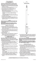
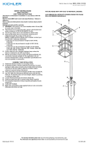
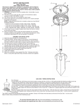
ASSEMBLY AND INSTALLATION
1) Determine desired location for mounting xture.
2) At desired location, hammer stake into ground. To avoid damage to stake, place a board on top of
stake while hammering. If ground is hard and stake is difcult to install, make a crosscut in ground
using a at shovel.
3) Clear away area in ground at wireway slot in top of stake.
4) Lay 12V cable into wireway slot and screw xture into stake. Aim xture in desired direction and
secure by tightening locknut. If necessary, use wrench or pliers for nal tightening of nut.
5) Adjust angle of xture by loosening hex head screw.
6) TURN OFF POWER.
7) Make wire connections using supplied wire connectors following instructions included, or using
other approved wiring connection method (not supplied).
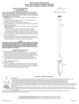
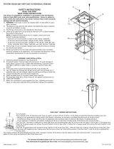
TO CHANGE LIGHT OUTPUT SETTING:
• NOTE: Fixure switches up in terms of lumen settings; it starts at low (500 lumens). If this level is
desired, no adjustment is needed.
• Locate the dimple at the side of the xture. (This is called a lumen adjustment switch locator)
• Hold magnet on lumen adjustment switch locator for 1.5 seconds to begin programming mode.
Remove magnet.
• Fixture will blink continuously 4x’s at full brightness level and go dark for 2 seconds and then will
illuminate at original factory setting.
• To switch lumen settings, magnet must be reapplied to lumen adjustment switch locator for 1.5
seconds and magnet must be removed for 1 second between switching.
• NOTE: xture blinks 1x for the lowest lumen setting; 2x’s for the middle lumen setting, and 3x’s for
the highest lumen setting.
• Once the xture is set and magnet removed, it stays in programming mode for 2 minutes.
• After 2 minutes, the memory is set.
• To change the output brightenss, return to programming mode by holding magnet on magnetic
locator for 1.5 seconds.
• NOTE: Fixture reverts back to original factory setting when put back into programming mode.
• NOTE: Once the desired setting is set, mark the level (1, 2, or 3) with a marker on xture under the
cowl.
For warranty information please visit: http://www.landscapelighting.com/portal/warranty_page
Para informacion de la garantia por favor visite: www.landscapelighting.com/portal/warranty_page
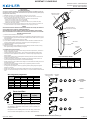
* DENOTES FACTORY SETTING
PROGRAMMING MODE
LUMEN ADJUSTMENT
SWITCH LOCATOR
SWITCHING
MAGNET
ORIGINAL
PROGRAMMING
MODE
LEVEL 1
LEVEL 2
LEVEL 3
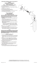
WireGauge/Power/LengthChart
10 12 14 16
020 1860/567 1150/351 730/223 450/137
40 930/283 580/177 370/113 230/70
60 620/189 390/119 240/73 150/46
80 470/143 290/88 180/55 110/34
100 370/113 230/70 140/43 90/27
>100
ConsultTechnicalSupport
WATTS(VA)
WireGauge/Length(ft/m)perrun
LUMEN ADJUSTMENT
SWITCH LOCATOR
FIXTURE
HEX HEAD SCREW TO
ADJUST ANGLE OF FIXTURE
LOCKNUT
STAKE
WIRE LEADS
SWITCHING
MAGNET
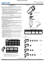
NOTE: When sizing your transformer please use the highest VA you expect to
use depending on desired lumen level per xture to prevent potentially over-
loading the transformer.
Best practice is to use VA/wattage buffer of 30% when sizing a transformer to
account for xture lumen adjustments. (ie. 210 VA on 300VA transformer.)
Fixture Load Chart
Lumen Level
VA (AC Power
Supplies)
WATTS (DC Power
Supplies)
3 23 18.5
2 16 12.5
1 9 7
1 9 7
IMPORTANT! PLEASE READ
Gen 3 Lumen Table for IS - 11302017.xlsx
Level 1 Level 2 Level 3
Lumen Level Table (For 2700K/3000K)
Single Flood LED
16022
*500 Lm 900 Lm700 Lm
Confidential 1Confidential 1

Customer Service: 866-558-5706
Technical Support: 844-452-4537
Hrs: M-F 9am to 5pm EST
IS-16022-US
Date Issued: 12/06/17
INSTRUCCIONES DE SEGURIDAD
LEA ESTO PRIMERO
CONSERVE ESTAS INSTRUCCIONES
Este artefacto está diseñado para ser instalado de acuerdo con las especicaciones del Código Nacional de
Electricidad (NEC) y del Código Local. El incumplimiento con estos códigos e instrucciones podrá provocar
lesiones graves y / o daños a la propiedad y anulará la garantía.
1) ADVERTENCIA: Este artefacto no se debe instalar a menos de 10 pies (3m) de una piscina, spa o fuente.
2) De acuerdo con los requisitos del Código Nacional de Electricidad (NEC), el cable para enterramiento
directo debe ser enterrado un mínimo de 6 pulgadas [152mm] debajo de la supercie del suelo.
NOTA: Si se necesita cable para enterramiento directo adicional, póngase en contacto con su distribuidor
local Kichler®.
• El cable 8 GA puede ser comprado en longitudes de 250 pies (76m), 15503-BK.
• El cable 10 GA puede ser comprado en longitudes de 250 pies (76m), 15504-BK.
• El cable 12 GA puede ser comprado en longitudes de 100 pies (30m), 15501-BK; 250 pies (76m),
15502-BK; 500 pies (152m),15505-BK; y 1000 pies (304m), 15506-BK.
3) Las conexiones de cableado deben realizarse con el (los) dispositivo (s) de conexión de cable aprobado /
listado adecuado para la aplicación. No exceda las especicaciones de combinación del cableado del
fabricante para el tamaño y la cantidad de conductores.
PRECAUCIÓN
AL INSTALAR LA ILUMINACIÓN DE PAISAJE DE KICHLER (VOLTAJE DE LÍNEA O BAJA TENSIÓN), DEBE
TENERSE CUIDADO PARA MANTENERLO LIBRE DE MATERIALES POTENCIALMENTE COMBUSTIBLES.
CUANDO MANTENGA LOS ARTEFACTOS, ASEGÚRESE DE RETIRAR LAS HOJAS, AGUJAS DE PINO, RE-
CORTES DE PASTO, ABONO, O CUALQUIER DESPERDICIO QUE SE HAYA ACUMULADO EN EL FOCO
(BOMBILLA), LENTE, O CUERPO DEL ARTEFACTO.
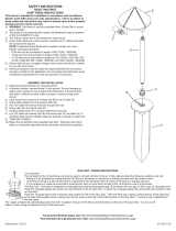
ENSAMBLAJE E INSTALACIÓN
1) Determine la ubicación deseada para el montaje del artefacto.
2) En la ubicación deseada, martille la estaca en el suelo. Para evitar daños a la estaca, coloque una tabla en
la parte superior de la estaca mientras martillea. Si la tierra es dura y la estaca es difícil de instalar, haga
un corte cruzado en la tierra con una pala plana.
3) Despeje el área en el suelo en la ranura de cable en la parte superior de la estaca.
4) Coloque el cable de 12V en la ranura del cableado y je el artefacto en la estaca. Apunte el artefacto en la
dirección deseada y asegúrelo apretando la tuerca de seguridad. Si es necesario, utilice una llave o un
alicate para el ajuste nal de la tuerca.
5) Ajuste el ángulo del accesorio aojando el tornillo de cabeza hexagonal.
6) DESCONECTE LA ENERGÍA.
7) Realice las conexiones de cable utilizando los conectores de cable suministrados siguiendo las instruc
ciones incluidas, o usando otro método de conexión de cableado aprobado (no suministrado).
PARA CAMBIAR EL AJUSTE DE SALIDA DE LUZ:
NOTA: El artefacto cambia en términos de ajustes del lumen; comienza a bajo (500 lúmenes). Si se desea este
nivel, no es necesario ningún ajuste.
• Localice el hoyuelo en la parte lado del artefacto. (Esto se llama un localizador de interruptor de ajuste
de lumen)
• Mantenga el imán en el localizador del interruptor de ajuste del lumen durante 1.5 segundos para empezar
el modo de programación. Remueva el imán.
• El artefacto parpadeará continuamente 4 veces en el nivel de brillo total y se apagará durante 2 segundos y
luego se iluminará en el ajuste original de fábrica.
• Para cambiar los ajustes del lumen, el imán debe volver a aplicarse al localizador del interruptor de ajuste
del lumen durante 1.5 segundos y el imán debe retirarse durante 1 segundo entre la conmutación.
NOTA: el artefacto parpadea 1 vez para el ajuste de lumen más bajo; 2 veces para el ajuste del lumen
medio y 3 veces para el ajuste del lumen más alto.
• Una vez que se ja el artefacto y se remueve el imán, éste permanece en el modo de programación
durante 2 minutos.
• Después de 2 minutos, la memoria está establecida.
• Para cambiar la luminosidad de la salida, vuelva al modo de programación manteniendo el imán en el
localizador magnético durante 1.5 segundos.
• NOTA: El artefacto vuelve a la conguración original de fábrica cuando se vuelve a poner en modo de
programación.
• Nota: Una vez ajustado el ajuste de lumen deseado, marque el nivel (1, 2 ó 3) con un
marcador en el accesorio debajo del capó.
For warranty information please visit: http://www.landscapelighting.com/portal/warranty_page
Para informacion de la garantia por favor visite: www.landscapelighting.com/portal/warranty_page
* INDICA AJUSTE DE FÁBRICA
MODO DE PROGRAMACIÓN
LOCALIZADOR DEL INTER-
RUPTOR DE AJUSTE DE
LUMEN
IMÁN DE CONMUTACIÓN
MODO DE
PROGRAMACIÓN
ORIGINAL
NIVEL 1
NIVEL 2
NIVEL 3
TabladeCalibre/Potencia/LargodelCable
10 12 14 16
020 1860/567 1150/351 730/223 450/137
40 930/283 580/177 370/113 230/70
60 620/189 390/119 240/73 150/46
80 470/143 290/88 180/55 110/34
100 370/113 230/70 140/43 90/27
Potencia
(W)
Calibre/LargodelCable(ft/m)
(Para 2700K/3000K) Nivel 1 Nivel 2 Nivel 3
LED de Una Sola
Inundación
16018-16020
*500 Lm 700 Lm 900 Lm
Tabla de Nivel de Lumen
LOCALIZADOR DEL INTER-
RUPTOR DE AJUSTE DE
LUMEN
ARTEFACTO
TORNILLO HEXAGONAL PARA
AJUSTAR EL ÁNGULO DEL ARTEFACTO
TUERCA DE SEGURIDAD
ESTACA
CABLES
CONDUCTORES
IMÁN DE
CONMUTACIÓN
NOTA: Cuando dimensione su transformador use el VA más alto que es-
pera usar dependiendo del nivel de lumen deseado para evitar sobrecar-
gar potencialmente el transformador.
La mejor práctica es utilizar VA / vatiaje de amortiguación del 30% al di-
mensionar un transformador para tener en cuenta los ajustes del lumen
del aparato. (Es decir) 210 VA en el transformador 300VA
IMPORTANTE! DEBE LEER
Tabla de Carga del Artefacto
Nivel de
Lumen Llevel
VA (AC fuente de
alimentación)
WATTS (DC fuente
de alimentación)
3 23 18.5
2 16 12.5
1 9 7
1 9 7
-
 1
1
-
 2
2


Kichler Lighting 16022AZT30 Manual de usuario
- Tipo
- Manual de usuario
- Este manual también es adecuado para
en otros idiomas
Artículos relacionados
-
Kichler Lighting 16070AZT27R Manual de usuario
-
 Kichler Lighting 15850CO30R Manual de usuario
-
 Kichler Lighting 16027SS30 Manual de usuario
-
 Kichler Lighting 15322AGZ Manual de usuario
-
 Kichler Lighting 15821AZT27 Manual de usuario
-
 Kichler Lighting 15374BKT Manual de usuario
-
 Kichler Lighting 15315AZT Manual de usuario
-
Kichler Lighting 15361AZT Manual de usuario
-
 Kichler Lighting 15313TZG Manual de usuario
-
 Kichler Lighting 15318AZT Manual de usuario


