Kichler Lighting 15361AZT Manual de usuario
- Tipo
- Manual de usuario

SAFETY INSTRUCTIONS
READ THIS FIRST
KEEP THESE INSTRUCTIONS
This xture is intended for installation in accordance with the National
Electric Code (NEC) and Local code specications. Failure to adhere to
these codes and instructions may result in serious injury and/or property
damage and will void the warranty.
1) WARNING: This xture is not to be installed within 10 feet (3M) of a pool,
spa or fountain.
2) This xture is to be used only with a power unit (transformer) rated a
maximum of 300 W (25 AMPS) 15 volts.
3) The #18 ga. xture wire is not intended for direct burial.
4) Direct burial rated wire is to be buried a minimum of 6” (152mm) beneath
the surface of the ground.
NOTE: If additional Direct Burial wire is needed, contact your local Kichler
®
landscape distributor.
• 8 GA wire can be purchased in length of 250’ (76 M), 15503-BK.
• 10 GA wire can be purchased in length of 250’ (76 M), 15504-BK.
• 12 GA wire can be purchased in lengths of 100’ (30 M), 15501-BK; 250’
(76 M), 15502-BK; 500’ (152M), 15505-BK; and 1000’ (304 M), 15506-BK.
5) Fixture shall not use a tungsten halogen lamp unless the xture is marked
for use with such lamps.
6) Wiring connections must be made with approved/listed wire connection
device(s) suitable for the application. Do not exceed manufacturers’ wiring
combination specications for size and quantity of conductors.
ASSEMBLY AND INSTALLATION
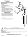
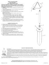
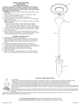
1) Determine desired location for mounting xture.
2) At desired location, hammer stake (A) into ground. To avoid damage to
stake, place a board on top of stake while hammering. If ground is hard
and stake is difcult to install, make a crosscut in ground using a at shovel.
3) Clear away area in ground at wireway slot (J) in top of stake (A).
4) Screw jam nut (B) onto end of stem (C).
5) Lay 12V cable into wireway slot (J) and screw stem into stake (A). If assembly
does not look straight, adjust by pushing or pulling on stake only.
6) Install provided lamp (E) to socket (F) inside xture body (D).
7) Align holes in diffuser (G) with threaded holes in xture body (D).
8) Secure diffuser (G) in place using thumbscrews (H).
9) TURN OFF POWER.
10) Make wire connections using supplied Quic Disc
™
following instructions
below, or using other approved wiring connection method (not supplied.)
11) Adjust angle of xture body by loosening screw (K) at center of swivel.
12) Adjust direction of xture by using jam nut (B) against stake (A).
For warranty information please visit: http://www.landscapelighting.com/portal/warranty_page
Para informacion de la garantia por favor visite: www.landscapelighting.com/portal/warranty_page
Date Issued: 12/2/11 IS-15361-US
A
C
K
H
D
E
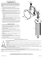
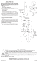
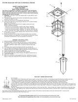
QUIC DISC
™
WIRING INSTRUCTIONS
Turn off power.
The full length of the 18 GA xture wire may be used to connect with the 10 GA or 12 GA cable provided the following conditions are met:
• Wiring is to be protected by routing close to the xture or accessory or secured to a building structure such as house or deck.
• 18 GA xture wiring is to be cut off so that it is attached to the connector within 6 inches of the xture or building structure.
• If it is necessary to make the connections underground, then no more than 6 inches of the 18 GA xture wire is to be buried.
The Quic Disc
™
connector is designed to install one xture and accommodates one 18 GA xture wire and one 10 GA or one 12 GA supply wire.
Place the 10 gauge supply wire across the area marked 10 GA on Quic Disc
™
or place the 12 gauge supply wire across the area marked 12 GA
on Quic Disc
™
.
Place the 18 gauge xture wire across the area marked 18 GA on the Quic Disc
™
. After the wires are in place, connect the top of the Quic Disc
™
to the base with supplied screw, making sure that the wires remain at in the bottom portion of the Quic Disc
™
, and the screw is tightened all the
way down.
The copper contacts will automatically pierce the wires’ insulation. Excess 18 GA xture wire that sticks out the end of the Quic Disc
™
is to be cut off.
Make no other wiring connections to the 18 GA xture wire.
B
J
G

INSTRUCCIONES DE SEGURIDAD
PRIMERO LEA ESTO
GUARDE ESTAS INSTRUCCIONES
Este artefacto se debe instalar de acuerdo con el Código Eléctrico
Nacional (NEC, por sus siglas en inglés) y con las especicaciones del
código local. No cumplir con estos códigos e instrucciones puede
resultar en lesiones graves y/ o en daños a la propiedad y anulará la
garantía.
1) Advertenciaertencia: Este artefacto no debe instalarse a menos de
10 pies (3 m) de una piscina (alberca), spa o fuente.
2) Este artefacto debe utilizarse solamente con una unidad de potencia
(tranformador) con capacidad nominal máxima de 300 vatios (25 amp.)
15 voltios.
3) El alambre del artefacto calibre No. 18 no es para soterrado directo.
4) El alambre clasicado para soterrado directo se debe enterrar un mínimo
de 6 pulgadas (152 mm) debajo de la supercie del terreno.
NOTA: Si necesita alambre de soterrado directo adicional, comuníquese
con su distribuidor local Kichler® de productos de jardinería ornamental.
• El alambre calibre 8 puede comprarse en longitud de 250’ (76 m.),
15503-BK
• El alambre calibre 10 puede comprarse en longitud de 250’ (76 m.),
15504-BK
• El alambre calibre 12 puede comprarse en longitudes de 75’ (22 m.),
15550-BK; 100’ (30 m.), 15501-BK; 250’ (76 m.), 15502-BK; 500’ (152 m.),
15505-BK; y 1000’ (304 m.), 15506-BK.
5) El artefacto no debe utilizarse con lámparas de halógeno, a menoss que
el artefacto esté marcado para usar con tales lámparas.
6) Las conexiones de cableado se deben hacer con las conexiones del(los)
dispositivos) de conexión de cableado aprobados/ de la lista, adecuados
para la aplicación. No exceda las especicaciones de combinación de
cableado del fabricante para el tamaño y cantidad de conductores.
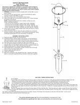
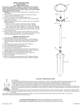
MONTAJE E INSTALACIÓN
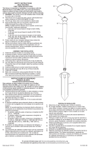
1) Determine el lugar deseado para montar el artefacto.
2) En el lugar deseado, martille la estaca (A) en el suelo. Para evitar dañar
la estaca, coloque una tabla en la parte superior de la estaca mientras esté
martillando. Si el suelo es duro y es difícil instalar la estaca, haga un corte
cruzado en el suelo usando una pala plana.
3) Limpie el área del terreno en la ranura (J) del canal de cables en la parte
superior de la estaca (A).
4) Atornille la contratuerca (B) en el extremo del vástago (C).
5) Coloque un cable de 12 V en la ranura (J) del canal de cables y atornille el
vástago en la estaca (A). Si el montaje no parece derecho, ajuste empujando o
estirando de la estaca solamente.
6) Instale la bombilla (E) que se provee al casquillo (F) dentro del cuerpo (D) del
artefacto.
7) Alinee los agujeros en el difusor (G) con los agujeros roscados en el cuerpo (D)
del artefacto.
8) Asegure el difusor (G) en su lugar usando tornillos de mariposa (H).
9) APAGUE LA ALIMENTACIÓN ELÉCTRICA.
10) Haga las conexiones de cableado usando el Quic Disc
™
suministrado y siguiendo
las instrucciones de abajo, o usando otro método de conexión de cableado
aprobado (no se suministra.)
11) Ajuste el ángulo del artefacto aojando el tornillo (J) en el centro de la rótula (K).
12) Ajuste la dirección del artefacto utilizando la contratuerca (B) contra la estaca (A).
Date Issued: 12/2/11 IS-15361-US
For warranty information please visit: http://www.landscapelighting.com/portal/warranty_page
Para informacion de la garantia por favor visite: www.landscapelighting.com/portal/warranty_page
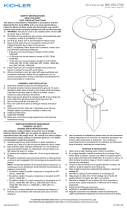
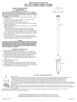
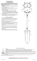
INSTRUCCIONES DE ALAMBRADO DE QUIC DISC
™
Apague la alimentación de energía.
El largo total del alambre calibre 18 del artefacto se puede utilizar para conectar con un cable calibre 10 ó 12, con tal que se cumplan las condi-
ciones siguientes:
• El alambrado se debe proteger encaminando cerca al artefacto o accesorio o asegurado a la estructura de un edicio, tal como una casa o
cubierta.
• El alambrado calibre 18 del artefacto debe cortarse de manera que se una al conector dentro de las 6 pulgadas del artefacto o de la estructura
del edicio.
• Si fuere necesario hacer las conexiones bajo tierra, como máximo 6 pulgadas del alambre calibre 18 del artefacto se debe enterrar.
El conector Quic Disc
™
está diseñado para instalar un artefacto y acomodar un alambre de artefacto de calibre 18 y otro de calibre 10, o bien un
alambre de alimentación de calibre 12.
Coloque el alambre de alimentación calibre 10 a través del área marcada calibre 10 en el Quic Disc
™
o ponga el alambre de alimentación calibre
12 a través del área marcada calibre 12 en el Quic Disc
™
.
Ponga el alambre calibre 18 del artefacto a través del área marcada calibre 18 en el Quic Disc
™
.
Después que los alambres estén en su lugar, conecte el tope del Quic Disc
™
a la base con el tornillo que se provee, asegurándose de que los alambres
permanezcan en la porción inferior del Quic Disc
™
, y el tornillo esté todo apretado hacia abajo.
Los contactos automáticamente perforarán la aislación de los alambres. El exceso de alambre calibre 18 del artefacto que sobresale del extremo Quic Disc
™
debe
cortarse.
No haga otras conexiones de cableado al alambre del artefacto de calibre 18.
A
C
K
H
D
E
B
J
G
-
 1
1
-
 2
2


Kichler Lighting 15361AZT Manual de usuario
- Tipo
- Manual de usuario
en otros idiomas
Artículos relacionados
-
 Kichler Lighting 15470AZT Manual de usuario
-
 Kichler Lighting 15410AZT Manual de usuario
-
 Kichler Lighting 15047OZ Manual de usuario
-
 Kichler Lighting 15315AZT Manual de usuario
-
 Kichler Lighting 15821AZT27 Manual de usuario
-
 Kichler Lighting 15314MST Manual de usuario
-
 Kichler Lighting 15336TZT Manual de usuario
-
 Kichler Lighting 15326AZT Manual de usuario
-
 Kichler Lighting 15313TZG Manual de usuario
-
 Kichler Lighting 15317AZT Manual de usuario


