
BR N
Moo ,sQp 0ss.QP SS.
EVOLUTION TM 4 P ge,
P4 Series Range oods
FOR DOMESTIC
wA..i.G &
TO REDUCE THE RISK OF FIRE, ELECTRIC SHOCK, OR
iNJURY TO PERSONS, OBSERVE THE FOLLOWING:
1. Use this unit only inthe manner intended by the manufacturer.
Ifyou have questions, contact the manufacturer at the address
or telephone number listed in the warranty.
2. Before servicing or cleaning unit, switch power off at service
panel and lock the service disconnecting means to prevent
power from being switched on accidentally. When the service
disconnecting means cannot be locked, securely fasten a
prominent warning device, such as a tag, to the service panel.
3. Installation work and electrical wiring must be done by a
qualified person(s) in accordance with all applicable codes
and standards, including fire-rated construction.
4. Sufficient air is needed for proper combustion and exhausting
of gases through the flue (chimney) of fuel burning equipment
to prevent backdrafting. Follow the heating equipment
manufacturer's guideline and safety standards such as those
published by the National Fire Protection Association (NFPA),
and the American Society of Heating, Refrigeration and
Air Conditioning Engineers (ASHRAE), and the local code
authorities.
5. This product may have sharp edges. Be careful to avoid cuts
and abrasions during installation and cleaning.
6. When cutting or drilling into wall or ceiling, do not damage
electrical wiring and other hidden utilities.
7. Ducted fans must always be vented to the outdoors.
8. Use only metal ductwork.
9. Do not use this fan with any solid-state speed control device.
10.As an alternative, this product may be installed with the
UL-approved cord kit designated for the product, following
instructions packed with the cord kit.
11.This unit must be grounded.
TO REDUCE THE RISK OFA RANGETOP GREASE FIRE:
1. Never leave surface units unattended at high settings.
Boilovers cause smoking and greasy spillovers that may
ignite. Heat oils slowly on low or medium settings.
2. Always turn hood ON when cooking at high heat or when
flamb6ing food (i.e. Crepes Suzette, Cherries Jubilee,
Peppercorn Beef Flamb_).
3. Clean ventilating fans frequently. Grease should not be
allowed to accumulate on fan or filter.
4. Use proper pan size. Always use cookware appropriate for the
size of the surface element.
TO REDUCE THE RISK OF iNJURY TO PERSONS IN THE
EVENT OF A RANGE TOP GREASE FIRE, OBSERVE THE
FOLLOWING:*
1. SMOTHER FLAMES with a close-fitting lid, cookie sheet,
or metal tray, then turn off the burner. BE CAREFUL TO
PREVENT BURNS. If the flames do not go out immediately,
EVACUATE AND CALLTHE FIRE DEPARTMENT.
2. NEVER PICK UP A FLAMING PAN --You may be burned or
spread the fire.
3. DO NOT USE WATER, including wet dishcloths or towels - a
violent steam explosion will result.
4. Use an extinguisher ONLY if:
A. You know you have a Class ABC extinguisher, and you
already know how to operate it.
B. The fire is small and contained in the area where it started.
C. The fire department is being called.
D. You can fight the fire with your back to an exit.
* Based on "Kitchen Firesafety Tips" published by NFPA.
CAUTION
1. For indoor use only.
2. For general ventilating use only. Do not use to exhaust
hazardous or explosive materials and vapors.
3. To avoid motor bearing damage and noisy and/or unbalanced
impeller, keep drywall spray, construction dust, etc., off power
unit.
4. Do not use over cooking equipment greater than 70,000
BTU/hr. as the blower motor will shut down intermittantly.
5. Your hood motor has a thermal overload which will
automatically shut off the motor if it becomes overheated. The
motor will restart when it cools down. If the motor continues
to shut off and restart, have the hood serviced.
6. The top of the hood MUST NOT BE LESS than 30" and at a
maximum of 36" above cooktop for best capture of cooking
impurities.
7. This hood is not intended to be used as a shelf.
8. Please read specification label on product for further
information and requirements.
- Register your product online at: www.broan.corn -
Installer: Leavethis manual
with the homeowner.
Homeowner:Cleaning, Maintenance and
Operating instructionson page2.

BR N
MODELS QP430SS ,, QP436SS ,, QP442SS
Page 2
CONTENTS OPERATION
INCLUDED WITH THE HOOD:
(1) 31A,,X 14,,
DAMPER / DUCT
CONNECTOR
FILTERS
(2- FOR30"& 36" HOODS)
(3- FOR42" HOODS)
(4) I_
HALOGEN
BULBS
(1) 7" ROUND__
_A(I 1 DUCT
CONNECTOR
) VERTICAL
R DIVERTER
(1) PARTS BAG CONTAINING:
WIRE (9) BULB
SUCTION
NUTS
#8 X 1/4"
DUCT <J CUP TOOL
CONNECTOR
SCREWS _ (5)
#10 X 5/8"
RD. HD.
MOUNTING
SCREWS
Always turn the hood ON before cooking in order to establish an
air flow in the kitchen. After turning off the range, let the hood run
for a few minutes to clear the air.
Operate the hood as follows:
o o o o o o o o o
NOTE
The e_and e+e° buttons are used to adjust and toggle the menu
and timer settings.
'_ LIGHT (3-Pushbutton Switches 4=light Settings)
Turns the light on the low setting and activates a green indicator
above the button. Pressing the 2 button a second time activates the
night time setting and illuminates the C indicator.
• • Turns the light on the medium setting and activates a green
indicator above the button.
e
• • Turns the light on the high setting and activates a green
indicator above the button.
Pressing and holding the same light button again will turn the lights
off.
When the night time setting is active, pressing and holding the low
light setting button o_will turn the night time setting off.
CLEANING & MAINTENANCE
For performance, appearance, and health reasons, clean filter,
fan and grease-laden surfaces. Use only a clean cloth and mild
detergent solution on stainless and painted surfaces.
Clean all-metal filters in the dishwasher using a non-phosphate
detergent. Discoloration ofthe filter may occur if using phosphate
detergents, or as a result of local water conditions - but this will
not affect filter performance. This discoloration is not covered by
the warranty.
The motor is permanently lubricated and never needs oiling. If
the motor bearings make excessive or unusual noise, replace
the motor with the exact service motor. The impeller should also
be replaced.
Use 120 V,50W, shielded halogen bulbs - MR16 with GU10 base.
_::_1 FAN (3-Pushbutton Switches 4-fan speeds)
• Turns the fan on the low speed and activates a green indicator
above the button.
• e Turns the fan on the medium speed and activates a green
indicator above the button.
ee+®Turnsthe fan on the high speed and activates a green indicator
above the button. Pressing the e+eo button a second time activates
the boost fan speed and illuminates the @,) indicator.
Pressing and holding the same fan button again will turn the fan off.
When the boost speed is active, pressing and holding the high
speed button will turn the boost speed off.
NOTE
This hood utilizes an offset blower design to achieve greater
performance and lower sound levels. As a result, you may notice
that cooking impurities are more attracted to one side or appear
to be pulled-in faster than they appear on the opposite side. This
is completely normal. The hood has been designed and tested
to provide good capture of cooking impurities and odors under
all normal cooking conditions regardless of the cooking location
on the cooktop. Please note that cooking on the rear burners will
always result in the best capture of cooking impurities, regardless
of the hood design.

BR N
MODELS QP430SS ,, QP436SS ,, QP442SS
(J_ 10=MINUTE DELAY OFF
When your hood fan is on (any speed) press the (,_ button to
N
activate the delay off feature. When activated, the hood fan will
automatically turn off after 10-minutes has elapsed. The delay
feature is active when the following appear on the LED screen: A
green indicator illuminated above the delay (._ button, a numeric
countdown "10-0" and a clockwise rotating LED. The delay
button can be pressed once again, to stop the delay countdown.
Pressing the (._ button again will resume the delay countdown.
Pressing and holding the button will turn off the feature.
(_ TIMER
Press the Q button to activate the timer setting feature. Use
the o_and oe+ebuttons to reduce or advance the timer setting to
the desired duration. When the desired timer setting is reached,
allow 3 seconds without pressing any additional button or press
the _ button once again. The timer will then activate, and
the countdown will be displayed on the LED screen along with
an green indicator above the Q button. After the timer has
reached "0:00'; an audible beep will be heard. The beep will
continue until the timer button (_}) is pressed once again. The
timer countdown can be stopped at any time by pressing the
_) once again. Pressing the _._ button again will resume
the timer countdown. Pressing and holding the _}) button will
turn off the feature. Note that when both the timer and delay off
features are active together, the timer function will be illuminated
on the LED display, and the delay off countdown will be active,
but not displayed.
Page 3
CLOCK SETTING
Press the (,_ button once, the "hours" will begin blinking in the
LED screen. Use the 2 and ore buttons to set the appropriate
hours for the clock. A small indicator will illuminate in the left
corner of the LED screen to designate "pm'_After the hours are
set, press the (,_ button to advance the menu to the minute
selection.The minutes will begin blinking in the LED screen. Use
the _oand o+e buttons to set the minutes. Press the (_ button
again to advance the menu to select "display" settings.
DISPLAY (default from factory - display ON)
The LED screen will display the display feature -d-. Use the 2 or
e_ebutton to toggle the LED screen on (d on) or off (doFF). When
the display off (doFF) feature is selected, the LED display clock
illumination is disabled. Press the _ button again to advance
the menu to select the "Sleep" setting.
SLEEP MODE (default from factory - OFF)
The LED screen will display the "Sleep" feature -S-. Use the _o
or e+e button to toggle the Sleep feature on (S on) or off (S off).
When the Sleep on (S on) feature is selected, the LED screen
and fan/light LED indicators are disabled. The ambient light
sensor, delay-off and timer features will also be disabled. All
controls for the fan and light operation, including Heat Sentry,
are still active. Press the _ button again to advance the feature
menu to select the 'Ambient Light Sensor" setting. Note: To
access the feature menu when the Sleep Mode is active, press
and hold the (,_ button for 2 seconds.
FEATURE MENU
Your hood offers many settings that can be accessed and
adjusted by scrolling through the feature menu. Your hood fan
must be off to be able to activate and access the feature menu.
Pressing the _ button when the hood fan is off will activate the
feature menu. Pressing the _ button again when the feature
menu is active will scroll through the various features that can
be adjusted/set. When the feature menu is active, if a button is
not pressed within 10 seconds or after scrolling through all menu
settings, the feature menu will automatically be exited, and all
selected settings will be saved. A green indicator above the
icon will illuminate when the feature menu is active.The following
features can be adjusted sequentially:
AMBIENT LIGHT SENSOR (default from factory- Level 1 ON)
There are two level settings for the ambient light sensor. When
either of the two settings is active, the light sensor will detect a low
level of light in your kitchen, and will automatically turn the task
lights on the hood to the night time setting. The other light settings
are still functional. If selected when the ambient light sensor is
active, they will temporarily overide the ambient light sensor until
they are turned off. The level 1(Aonl) ambient light sensor setting
will require your kitchen to be more dark than the level 2 (Aon2)
setting before activating the night time setting. The LED screen
will display the ambient light sensor function -A-. Use the _oor e+ee
button to select the light sensor setting Aonl, Aon2, or AoFE The
Off (AoFF) setting deactivates the automatic ambient light sensor
feature so the night time light operation is manual.
Note that the feature menu can be exited any time by not
pressing any button(s) for 10 seconds or by scrolling through the
entire feature menu.

BR N
MODELS QP430SS ,, QP436SS ,, QP442SS
HEAT SENTRY SYSTEM
This range hood is equipped with an advanced Heat Sentry
system that monitors excessive temperature and automatically
adjusts the fan to the appropriate setting.
1) If the fan is on the Heat Sentry system will increase the
fan setting when the temperature is elevated. If the temperature
continues to rise, the Heat Sentry system will continue to increase
the fan setting until the temperature is stabilized or reduced.The
flashing light above the fan button shows the Heat Sentry system
fan setting. Once the temperature has reduced, the Heat Sentry
system will change the fan to the original setting.
2) If the fan is off the Heat Sentry system will automatically turn
the fan on to its highest speed when the temperature is above
normal. When the Heat Sentry system is on, the light above the
high speed fan button will flash on and off. After the temperature
has lowered to normal, the fan speed will be reduced until the
temperature has stabilized, then the fan will turn off.
- Note: Canadian version does not have this function. -
FUSES
RANGE HOOD CONTROL BOARD
MAIN LIGHT
FUSE FUSE
Page 4
MAKE-UP AIR DAMPER
The hood is compatible with Broan Make-Up Air Damper Model
MD6T or Model MD8T (optional). Purchase separately.
Make the connection to the Make-Up Air Damper with low voltage
wiring, as shown. See Make-Up Air Damper instructions for
additional information.
l ® o
/ BACK OF HOOD
/
I
LOW-VOLTAGE CONNECTOR
FOR MAKE-UP AIR DAMPER
RANGE
HOOD
LOW-VOLTAGE
WIRES
¢----
120
VAC__
MAKE-UP AIR
DAMPER
DAMPER
MOTOR
REMOTE CONTROL
The hood is compatible with Broan RF Remote Control Model
BCR1 (optional). Purchase separately.
The Range Hood Control Board contains a Main Fuse and a
Fuse to protect the controls from power surges. Ifa fuse has
opened (blown), the green fan setting or light setting indicators will
not operate properly when the fan or light buttons are pressed, and
the fan and lights will not turn on.
New fuses can be purchased at your local electronic supply store.
Use 8A, 120V, 5 mm diameter, 20 mm long, fast-acting, cartridge-
type fuses.
To replace a fuse (by qualified person(s):
1. Disconnect power at service entrance.
2. Remove filters and bottom pan.
3. Remove and inspect fuse. If it is not open (blown), additional
diagnostics are needed.

BR N
MODELS QP430SS ,, QP436SS ,, QP442SS
Page 5
PREPARE HOOD LOCATION
53
ROOF CAP 3%" X 14" or
7" ROUND DUCT
(For vertical
discharge)
HOUSE WIRING
or Back of hood)
CAP
t HOOD
30"- 36" ABOVE 3%"X 14" DUCT
COOKING SURFACE
(For horizontal discharge)
Determine whether hood will discharge vertically (3W'
x 14" or 7" Round), or horizontally (3W' x 14" only). For
vertical or horizontal discharge, run ductwork between
the hood location and a roof cap or wall cap. For best
results, use a minimum number of transitions and elbows.
Use the proper diagram, as follows, for placement of
ductwork and electrical cutout in cabinet or wall.
VERTICAL DISCHARGE
CABINET FRONT DUCT & ELECTRICAL CUTOUTS
m I
I
t ELECTRICAL
CENTER ACCESS HOLE
LINE (in cabinet bottom)
HORIZONTALDISCHARGE
DUCT & ELECTRICAL CUTOUTS
35/8"
II mC ,.ETFRO.Tj3Js"ll-
I .OR,ZO.TALOOCTIT=H9
1 4" L AccEss.oLEj ,( _CABINET ._
oo,,oo
t
CENTER
LINE
"_ ELECTRICAL
ACCESS
HOLE
(in wall)
MAKE-UPAIR
DAMPER ELECTRICAL
CONNECTION HOLE
(in wall)
7=INCHROUND DISCHARGEDUCT & ELECTRICAL CUTOUTS
CABINET FRONT
ELECTRICAL
CENTER ACCESS HOLE
LINE (in cabinet bottom)
30" HOOD
MOUNTING SCREW LOCATIONS
12 13/16" 115/8"
115/8" t"
WOOD SHIMS l HOOD MOUNTING
(recessed-bottom CENTER LINE SCREWS (5)
cabinets only)
36" & 42" HOODS
MOUNTING SCREW LOCATIONS
I45/8" (36" hood) 145/8" (36" hood)
_- 175/8" (42" hood) -_ 175/8" (42" hood)
CABINET FRONT I 3/
ii CABINET I'11_
I
WOOD SHIMS t'
(recessed-bottom CENTER
cabinets only) LINE
HOOD MOUNTING
SCREWS (5)

BR N
MODELS QP430SS • QP436SS • QP442SS
Page 6
PREPARE THE HOOD
Remove parts bag and 3W' x 14" damper/duct connector
from inside the hardware box included with the hood.
Remove all protective polyfilm from the hood.
El Remove 6 Screws holding Bottom Pan to hood. Set bot-
tom pan and screws aside.
SCROLL
CAP
BUSHING _ °
I
_ SCREWS
LEFT-HAND
LIGHT PANEL
7" ROUND
DUCT
PLATE
VERTICAL 7" ROUND & 3W' X 14" INSTALLATION
ONLY:
Attach 3W' x 14" Damper/Duct Connector (if using 3W'
x 14" duct) or 7" Round Duct Plate (if using 7-inch round
duct) over the knockout opening.
Notes:
To accomodate off-center ductwork, the 3W'x 14" damper/
duct connector can be installed up to 1/2"on either side
of the hood center and the 7" round duct plate can be
installed up to W' on either side of the hood center.
Install the 3W'x 14" Damper/Duct Connector with the
Damper Flap Pivot nearest the Top/Back Edge of Hood.
FOR 30" MODEL ONLY:
Remove Le_Hand Light Panel by removing (2) Screws
and disconnecting electrical connector.
Remove Rubber Bushing in Scroll Cam. Set parts aside.
7" ROUND
KNOCKOUT
PLATE (also .......
remove 3W'x 14" <%
vertical plate)
./_ (_ 31A"X 14"
VERTICAL
KNOCKOUT
3W' X 14" .1_j PLATE
®
KNOCKOUT
PLATE
3 Remove 3_A'' x 14"vertical, 3W' x 14" horizontal, or 7-inch
round Knockout Plate(s) as appropriate for your ducting
method.
I_ HORIZONTAL 3W' X 14" INSTALLATION ONLY:
Remove and discard Vertical Diverter Plate.

BR N
MODELS QP430SS ,, QP436SS ,, QP442SS
INSTALL THE HOOD
_ ARNING
To reduce the risk of electrical shock, switch power off
at service panel. Lock or tag service panel to prevent
power from being switched on accidentally.
ELECTRICAL
WIRING BOX
COVER
ELECTRICAL
POWER
CABLE
KNOCKOUT
J
El Remove Electrical Wiring Box Cover from inside
of hood and appropriate Electrical Power Cable
Knockout from top or back of hood.
Page 7
CONNECT THE WIRING
GROUND
SCREW
El
HOUSE POWER CABLE
Connect House Power Cable to range hood wiring -
BLACK to BLACK, WHITE to WHITE, and GREEN or
BARE WIRE to Ground Screw. Replace electrical wiring
box cover.
FOR 30" MODEL ONLY:
Replace rubber bushing, re-connect left-hand light panel
electrical connector, and re-attach light panel with (2)
screws removed in Step 6.
Re-attach Bottom Pan with 6 Screws removed in Step 5.
Install aluminum filters.
HOWTO CHANGE LIGHT BULBS
o I
HOUSE
POWER CABLE
[_ Run House Power Cable between service and hood
panel
location. Attach power cable to hood using appropriate clamp.
[_ Hang hood from (4) mounting screws driven into
part-way
cabinet locations (shown in illustrations under "PREPARE
HOOD LOCATION"). Mounting screws are included in
parts bag. Slide hood back towards wall until mounting
screw heads are engaged in narrow end of keyhole slots
in top of hood. Tighten screws securely. Add 5th mounting
screw in center hole in hood and tighten securely.
[_ Connect ductwork hood and duct make
to use
tape
to
joints secure and air-tight. Make sure the damper/duct
connector enters the ductwork and that the damper opens
and closes freely.
CAUTION: Bulbs may be hot. Refer to bulb
packaging for further information.
Install (4) _en Bulbs (included with hood). Use 120 V, 50
W, shielded halogen bulbs - MR16 with GU10 base.
NOTE: Suction CupTool (included with hood) can be used to
install and remove light bulbs.
Align pins on bulb with large diameter opening on socket, then
push bulb in towards hood and rotate clockwise until firmly
seated.
The position of the bulb socket (depth) is adjustable and may
require adjustment when:
a) certain brands of bulbs are difficult to install.
b) the bulb protrudes too far below the light panel.

BR N
MODELS QP430SS ,, QP436SS ,, QP442SS
LAMP SOCKET
BRACKET
LIGHT
PANEL SCREWS
To change the depth of bulb sockets:
1. Remove bottom pan (See Step 5).
2. Remove 2 _ht Panel Screws and _ Panel. Set
screws aside.
3. Loosen 2 Screws holding Lamp Socket Bracket to
Panel.
4. Adjust socket/bracket to desired depth.
5. Re-tighten screws securely.
6. Re-attach light panel and bottom pan.
SERVICE PARTS
Page 8
WARRANTY
OneYearLimitedWarranty
Broan-NuTonewarrantsto the originalconsumerpurchaserof its products
that suchproductswill be freefrom defectsin materialsor workmanship
for a periodof one(1) yearfrom thedateoforiginalpurchase.THEREARE
NOOTHERWARRANTIES,EXPRESSORIMPLIED,INCLUDING,BUTNOT
LIMITEDTO,IMPLIEDWARRANTIESOFMERCHANTABILITYOR FITNESS
FORA PARTICULARPURPOSE.
Duringthis oneyear period, Broan-NuTonewill, at its option, repairor replace,
without charge,any product or partwhich isfound to bedefectiveundernormal
use and service. THIS WARRANTY DOESNOT EXTENDTOFLUORESCENT
LAMP STARTERS,TUBES, HALOGENAND INCANDESCENTBULBS,FUSES,
FILTERS,DUCTS,ROOFCAPS,WALL CAPSANDOTHERACCESSORIESFOR
DUCTING.This warranty does not cover (a) normal maintenanceand service
or (b) any products or parts which havebeensubject to misuse, negligence,
accident, improper maintenanceor repair(other than by Broan-NuTone),faulty
installation or installation contrary to recommendedinstallation instructions.
The duration of any implied warranty is limited to the one year period as
specifiedfor the expresswarranty.Some statesdo notallow limitation on how
long animplied warranty lasts, sotheabove limitation maynot applyto you.
BROAN-NUTONE'SOBLIGATIONTO REPAIR OR REPLACE, AT BROAN-
NUTONE'SOPTION,SHALL BE THE PURCHASER'SSOLEAND EXCLUSIVE
REMEDYUNDERTHISWARRANTY.BROAN-NUTONESHALLNOTBELIABLE
FORINCIDENTAL,CONSEQUENTIALORSPECIALDAMAGESARISINGOUTOF
OR IN CONNECTIONWITH PRODUCTUSE ORPERFORMANCE.Somestates
donot allowthe exclusionor limitationof incidental or consequentialdamages,
so theabove limitation or exclusion maynot applyto you. Thiswarranty gives
you specific legal rights, and you may also haveother rights, which vary from
stateto state.This warranty supersedesall prior warranties.
To qualify for warranty service, you must (a) notify Broan-NuToneat the
address or telephone number below, (b) give the model number and part
identification and (c) describe the natureof any defect in the product or part.
At the time of requestingwarranty service, you must present evidenceof the
originalpurchasedate.
Broan-NuToneLLC,926 W.State Street,Hartford, Wisconsin53027
www.broan.com 800-558-1711
Rev.08/2007
KEYNO. PARTNO.
1 97018567
2 97018257
3
4
5
99528259
97018568
97018227
97018205
97018206
97018207
7 97018569
8 97018570
9 97018571
10 97018231
11 97017731
12 97018233
13 97018572
97018573
97018574
14 97018260
15 97018262
16 97018575
17 97018582
* 97017735
* 99526707
* 97018252
* 97018253
* 97018261
* V05921
DESCRIPTION
7" RoundDuctPlate(includesmounting hardware)
UserInterfaceAssembly Black(includes interface,
nameplate,mounting hardware)
Nameplate,Black
CapacitorKit (includeswire nuts, mounting screw)
LightPanelRHStainless
(includesmounting hardware)
FilterKitfor 30" (2 perbag)
FilterKitfor 36" (2 perbag)
FilterKitfor 42" (3 perbag)
BlowerWheel(includesspring clip)
Motor Kit (includesmotor, isolators,
mounting hardware)
Damper/Duct Connector(includes mounting
hardware)
LightPanelLH Stainless(includes mounting
hardware)
LampSocket(includeslampsocket,wire nuts,
mountingscrews)
LampSocketBracket
BottomPan30" (includesmounting hardware)
BottomPan36" (includesmounting hardware)
BottomPan42" (includesmounting hardware)
CircuitBoard
Transformer(includesmounting hardware)
VerticalDiverter
RubberBushing
PartsBag
SuctionCupTool
HeatSensor
Fuse
RibbonCableKit (contains3)
50WHalogenGUIO Bulb
* Not shown
Order replacementparts byPARTNO.- not by KEYNO.
99527577B

BR N
ooEL sQP4 OSS.QP4 SS.QP44 SS
EVOLUTION'" 4 P ge9
ottes de cuisine de s rie QP4
POUR USAGE DOMESTIQUE SEULEMENT
AVERTISSEME.TZ& AVERTISSEME.T
OBSERVEZ LES DiRECTiVES CI-DESSOUS AFIN DE RC:DUIRE
LES RISQUES D'INCENDIE, DE CHOC ¢:LECTRIQUE OU DE
BLESSURES CORPORELLES :
1. N'utilisezcetappareilquede la mani@eprevueparlefabricant.Si vous
avezdes questions,communiquezavecle fabricanta I'adresseou au
num@odetel@honeindiquesdansla garantie.
2. Avant de proceder& I'entretienou au nettoyagede rappareil,coupez
ralimentationdu panneauelectriqueet verrouillezrinterrupteurprincipal
din d'emp@herque le courantne soit accidentellementretabli.S'il est
impossibledeverrouillerrinterrupteurprincipal,fixezsolidementunmessage
d'avertissement,parexempleuneetiquelte,surle panneauelectrique.
3. La posede rappareil etles travauxd'electricite doivent6treeffectues
par des personnes qualifiees conformement & fa reglementation
en vigueur, notamment les normes de construction ayant trait & la
protection contre les incendies.
4. Pour@iterles refoulements,I'apportd'air dolt_tre suffisantpourbrOler
les gaz produitspar les appareils&combustionet les @acuerdartsle
conduitdefumee (cheminee).Respectezles directivesdu fabricantde
I'appareil de chauffageet les normes de securit& notammentcelles
publieesparla NationalFire ProtectionAssociation(NFPA),IAmerican
Society of Heating, Refrigeration and Air Conditioning Engineers
(ASHRAE)et lescodesdes autoriteslocales.
5. Ce produitpeutcomporter des ar_testranchantes.Prenezgarde aux
coupureset aux@afluresIorsde I'installationet dunettoyage.
6. Veillez & ne pas endommager le c&blage electrique ou d'autres
equipements non @parents lots de la decoupe ou du per_;agedu
tour ou du plafond.
7. Les ventilateurs canalises doivent toujours rejeterrair &rext@ieur.
8. N'utilisez que des conduits metalliques.
9. N'utilisezpas de commandede regime & semi-conducteursavec ce
ventilateur.
10. Ce produitpeut egalement6tre installe avec un ensemblede cordon
electrique homologue UL de conception speciale, en suivant les
instructionsaccompagnantI'ensemblede cordonelectrique.
11. Cetappareildolt6tre relie&une mise &la terre.
POUR REDUIRE LES RISQUES D'INCENDIE CAUSES PAR
DE LA GRAISSE SUR LE PLAN DE CUJSSON :
1. Nelaissezjamais lesel6mentsdesurfaceallumesahautetemp@ature.
Les debordements produisentde la fumee et des ecoulementsde
graisseinflammables.Ehuiledolt _trechauffeegraduellementa basse
ou &moyennetemp@ature.
2. Metteztoujours la hotte en MARCHEIors de la cuisson a feu vif ou
Iorsde lacuissond'aliments&flamber(parex.,cr@es Suzette,cerises
jubil& bceufau poivreflambe).
3. Nettoyezsouventla hotte.Ne laissezpas la graisses'accumulersur le
ventilateurou lesfiltres.
4. Utilisezdes casserolesde dimensionappropriee.Utiliseztoujoursune
batteriede cuisineadaptee& la dimensionde lasurfacechauffante.
OBSERVEZLES CONSlGNESSUIVANTESDE IVlANI#RE_. RE_DUIRE
LES RISQUESDE BLESSURESCORPORELLESEN CASD'INCENDIE
CAUSEPARDE LA GRAISSESUR LE PLANDE CUISSON:*
1. ETOUFFEZLES FLAMMES& I'aided'uncouvercleetanche,d'unet61e
biscuits ou d'un plateau en metalpuis eteignez le brOleur.FAITES
ATTENTIONDE NE PASVOUS BRULER. SI LES FLAMMES NE
S'ETEIGNENT PAS IMMEDIATEMENT,QUITTEZ LES LIEUX ET
APPELEZLESERVICEDESINCENDIES.
2. NERETIREZJAMAISUNEPOELEENFLAMMESDELACUISINIERE.
Vousrisquezdevous brOleret depropagerI'incendie.
3. N'UTILISEZ PASD'EAU,ni de serviettes ou de lingesmouilles - une
violenteexplosionde vapeurpourraitsurvenir.
4. UtilisezunextincteurSEULEMENTsi :
A. Vous savezqu'il est de classeABC et vous connaissezdej& son
modede fonctionnement.
B. Eincendien'estpastres important etnese propagepus.
C. Lespompiersontet6 avises.
D. VouspouvezcombattreI'incendieen faisantdos aune sortie.
* Conseilstires de lapublicationde laNFPA_KitchenFireSafetyTips _.
ATTENTION
1. Pourusageinterieurseulement.
2. Pourventilationgen@aleuniquement.Ne pasutilisercet appareilpour
evacuerdesmati@esoudesvapeurs dangereusesouexplosives.
3. Pourne pas endommagerles roulementsdu moteur,des@uilibrerles
pales ou les rendrebruyantes,prot_gez I'appareilde la poussi_rede
pl&tre,de construction,etc.
4. Ne pas utiliser cette hotte au-dessus d'un appareil de cuisson
d@assant70000BTU/heurecar lemoteurduventilateurs'arr_terapar
intermittence.
5. Lemoteurde lahotteestmunid'undispositifdeprotectiondesurcharge
electriquequi coupeautomatiquementle moteurencas de surchauffe.
II se remet en marche Iorsqu'ila refroidi.Faitesr@arer la hottesi le
moteurcontinue &fonctionnerparintermittence.
6. Pour mieux capter les vapeurs de cuisson, le bus de la hotte DOlT
ETREAU MINIMUMa76 cm (30po) etau maximum&91 cm (36po)
au-dessusde la surfacede cuisson
7. Cettehotten'estpas con_uepourservird'etag@e.
8. VeuillezlireI'etiquettede specificationsdu produitpourobtenir plusde
renseignements,notammentsur lesexigences.
- Enregistrez votre produit en ligne & : www.broan.corn. -
Installateur : Veuillez remettre
cemanuel au propri taire.
Propri taire : Nettoyage,entretien
et mode d'emploi la page 10.

BR N
MODI=LES QP430SS ,, QP436SS ,, QP442SS
Page 10
CONTENU FONCTIONNEIVIENT
INCLUS AVEC LA HOTTE "
t4)
AMPOU.LES "t_:_
HALOGENES
ill _----_.._ (1) CLAPET / RACCORD
_"_".._._ DE CONDUIT
_N__._-.........,_ 8,2 X 35,5 CM
-_1 (3,_POx14PO)
FILTRES A GRAISSES v-,
[2 - POUR LES HOTTES
DE 76 CM (30 PO)
ET 91 CM (36 PO)
3 - POUR LES HOTTES
DE 106 CM (42 PO)]
(1) RACCORD
_(I_,A DE CONDUIT ROND
DE 18 CM (7 PO)
REPARTITEUR
IR VERTICAL
(1) SACHET DE PIECES CONTENANT "
_ (1) VENTOUSE
(3) (9) _ _ POUR
SERRE-FILS VlS N° (_ AMPOULE
8 X 1/4 PO
POUR RACCORD
DE CONDUIT
(_ (5)
VlS DE .
MONTAGE A
TETE RONDE
N° 10 X 5/8 PO
Mettez toujours la hotte en MARCHE avant de cuisiner afin
d'6tablir une circulation d'air dans la cuisine. Laissez la hotte
fonctionner quelques minutes apr_s I'arr6t de la cuisini_re afin
de nettoyer I'air.
Pour utiliser la hotte, faites comme suit "
0 0 () ¢) 0 0 0
[_. .................................................................................".)
o o
REMARQUE
o
Les boutons e_et o+o servent A configurer le menu et la minuterie
et A passer de I'un A I'autre.
"_ ¢CLAIRAGE (3 boutons=poussoirs 4 r6glages d'_clairage)
• Allume 1'6clairage& faible intensit6 et active un t6moin vert au-
dessus du bouton. Appuyer de nouveau sur _oactive le reglage de
nuit et illumine le t6moin (_.
• ®Allume 1'6clairage A moyenne intensit6 et active un t6moin vert
au-dessus du bouton.
e
• o Allume I'eclairage A haute intensite et active un temoin vert
au-dessus du bouton.
Appuyer de nouveau sur le m6me bouton et le maintenir eteint
1'6clairage.
Lorsque le r6glage de nuit est activ6, appuyer de nouveau sur le
bouton d'6clairage & faible intensit6 _oet le maintenir d6sactive le
reglage de nuit.
NETTOYAGE ET ENTRETIEN
Pour des raisons de sant6, de performance et d'apparence,
nettoyez lefiltre, le ventilateur et les surfaces graisseuses. Utilisez
seulement un chiffon propre et une solution de d6tergent doux
sur I'acier inoxydable et les surfaces peintes.
Nettoyez les filtres enti_rement m6talliques au lave-vaisselle avec
un d6tergent sans phosphate. Une d6coloration du filtre peut se
produire si des d6tergents phosphat6s sont utilis6s et selon les
conditions locales de I'eau, sans toutefois affecter le rendement
du filtre. Cette d6coloration n'est pas couverte par la garantie.
Le moteur est lubrifi6 en permanence et n'a pas besoin d'6tre
huil& Si les roulements du moteur sont anormalement bruyants,
remplacez le moteur exactement par le m6me module. La roue
&ailettes doit aussi 6tre remplac6e.
Utilisez des ampoules halog_nes avec 6cran de 120 V, 50 W -
MR16 &culot GU10.
VENTILATEUR (3 boutons-poussoirs 4 r_gimes de ventilateur)
• Met le ventilateur en marche au regime lent et active un t6moin
vert au-dessus du bouton.
• o Met le ventilateur en marche au regime moyen et active un
t6moin vert au-dessus du bouton.
°+°eMet le ventilateur en marche au r6gime 61ev6 et active un
t6moin vert au-dessus du bouton. Appuyer de nouveau sur le
bouton o+o active le ventilateur & la vitesse maximale et illumine
le t6moin _¢,,).
Appuyer sur le m6me bouton et le maintenir arr6te leventilateur.
Lorsque la vitesse maximale est activee, appuyer sur le bouton de
regime 61ev6et le maintenir d6sactive la vitesse maximale.
REMARQUE
Cette hotte comporte un ventilateur & conception d6calee offrant
un meilleur rendement tout en r6duisant le niveau sonore. Par
consequent, vous remarquerez peut-6tre que les impuret6s de
cuisson sont davantage attir6es d'un c8t6 ou semblent aspir6es
plus rapidement que de I'autre c8t6, ce qui est normal. La hotte
a 6t6 con(_ue et test6e pour capter les impuret6s et odeurs de
cuisson dans des conditions normales, quel que soit I'endroit ot_ la
cuisson s'effectue sur la cuisiniere. Veuillez noter que cuisiner sur
les brMeurs arriere permet toujours une meilleure captation des
impuret6s de cuisson, quelle que soit la conception de la hotte.

BR N
iVIODI_LES QP430SS ,, QP436SS ,, QP442SS
(_, ARRET DIFFI_RE_DE 10 MINUTES
La hotte 6tant en marche (& n'importe quelle vitesse), appuyez
le bouton ('_ pour activer la fonction d'arr6t diff6r&
sur
Le ventilateur s'arr6tera automatiquement apr_s un d61ai de
10 minutes. La fonction d'arr6t diff6r6 est active Iorsque ce
qui suit apparaft sur 1'6cran DEL : Un t6moin vert s'allume au-
dessus du bouton d'arr6t diff6r6 ('_ , un compte & rebours
_,10 &0 _s'affiche ainsi que des DEL s'allument en tournant dans
le sens horaire. Appuyez de nouveau sur le bouton d'arr6t diff6r6
pour interrompre le compte & rebours. Appuyez de nouveau sur
pour reprendre le compte & rebours. Appuyer sur
le bouton
le bouton et le maintenir d6sactive cette fonction.
(_ MINUTERIE
Appuyez sur le bouton _!1 pour activer la fonction de minuterie.
Utilisez les boutons _eet eeo pour reculer ou avancer le r6glage
. +
de la minuterie & la duree voulue. Une lois la minuterie r6gl6e
comme souhait6, attendez 3 secondes sans appuyer sur aucun
autre bouton ou appuyez de nouveau sur le bouton _-J_.
La minuterie est alors activ6e et le compte & rebours s'affiche
sur 1'6cran DEL, tandis qu'un voyant vert s'allume au-dessus
du bouton ((_). Lorsque la minuterie atteint ,_0:00
un
signal
sonore se fait entendre. Le signal continue jusqu'& ce que I'on
ait appuy6 de nouveau sur le bouton ({_). Le compte &rebours
de la minuterie peut 6tre interrompu en tout temps en appuyant
de
nouveau sur le bouton ((-J)). Si vous appuyez encore une
fois
le bouton ((3_, la minuterie reprend le compte & rebours.
sur
Pour d6sactiver
cette fonction, appuyez sur le bouton (_ et
maintenez-le. Veuillez noter que si les fonctions de minuterie et
d'arr6t diff6r6 sont activ6es ensemble, la minuterie sera illumin6e
sur 1'6cran DEL, tandis que la fonction d'arr6t diff6r6 sera active
mais pas affich6e.
MENU DE FONCTIONS
Votre hotte comporte de nombreux r6glages auxquels vous
pouvez acc6der en faisant d6filer le menu de fonctions.
La hotte doit 6tre arr6t6e pour 6tre en mesure d'acc6der au menu
de fonctions. Appuyez sur le bouton (',_- pendant que la hotte
est arr6t6e pour activer le menu de fonctions. Pendant que le
menu est actif, appuyez de nouveau sur le bouton (,_ pour
faire
d6filer les diverses fonctions & r6gler ou configurer. Si le menu
de fonctions est actif mais qu'aucun bouton n'est press6 apr_s
10 secondes ou apr_s avoir fait d6filer tousles r6glages du
menu, la hotte quitte automatiquement le menu de fonctions et
tous les r6glages sont enregistr6s. Un t6moin vert s'allume au-
dessus de I'ic6ne (_i_.Iorsque le menu de fonctions est actif. Les
fonctions suivantes peuvent 6tre r6gl6es I'une apr_s I'autre :
Page 11
RE_GLAGE DE L'HEURE
Appuyez une fois sur le bouton (,_, les ,, heures >>commencent
& clignoter sur 1'6cran DEE Utilisez les boutons • et _o pour
regler correctement I'heure de I'horloge. Un petit t6moin s'allume
dans le coin gauche de I'ecran DEL pour indiquer ,, PM >>.Une
regl6e, appuyez sur le bouton _ pour avancer
lois I'heure
au menu de selection des minutes. Les minutes se mettent a.
chgnoter sur I'ecran DEE UtMsez les boutons oet o+o pour regler
les minutes.
Appuyez de nouveau sur le bouton _ pour avancer
au menu et selectionner _ Affichage >>.
AFFICHAGE (par d6faut _I'usine, Faffichage est EN MARCHE)
F6cran DEL affiche la fonction d'affichage -d-. Utilisez le
bouton _eou e+e pour passer entre 1'6cran DEL allum6 (d on)
ou 6teint (doFF). Lorsque la fonction d'affichage 6teint (doFF)
est s61ectionn6e, I'affichage DEL de I'horloge est d6sactiv&
Appuyez de nouveau sur le bouton (_ pour avancer au menu
de s61ection du <<Mode veilleuse ,,.
MODE VEILLEUSE (par d6faut _ I'usine - DESACTIVE)
F6cran DEL affichera la fonction <,Veilleuse >>-S-. Utilisez le
bouton • ou o+e pour passer entre la fonction Veilleuse activ6e
(S on) ou d6sactiv6e (S off). Lorsque la fonction Veilleuse est
activ6e (S on), 1'6cran DEL et les voyants DEL du ventilateur et
de 1'6clairage sont d6sactiv6s. Le capteur de lumi_re ambiante, la
fonction d'arr6t diff6r6 et la minuterie sont 6galement d6sactiv6s.
Les commandes du ventilateur et de 1'6clairage, y compris celles
du d6tecteur de chaleur, sont actives. Appuyez de nouveau sur
le bouton
pour avancer au menu et s61ectionner <<Capteur
de lumi_re ambiante >>.Remarque : Pour acc6der au menu de
fonctions Iorsque le mode Veilleuse est actif, appuyez sur le
bouton ('lL et maintenez-le 2 secondes.
CAPTEUR DE LUMI#RE AMBIANTE (par d6faut aI'usine - Niveau
1 MARCHE)
II y a deux r6glages de niveau pour le capteur de lumi_re
ambiante. Quand I'un ou I'autre niveau est actif, le capteur de
lumi_re d6tecte un faible niveau de lumi_re dans la cuisine et
r_gle automatiquement les t6moins de la hotte sur le mode de
nuit. Les autres r6glages de 1'6clairage demeurent fonctionnels.
Si la s61ection est effectu6e alors que le capteur de lumi_re est
actif, elle supplante temporairement le capteur de lumi_re jusqu'&
ce que 1'6clairage soit 6teint. Le r6glage du capteur de lumi_re
ambiante de niveau 1(Aonl) exige que la cuisine soit plus sombre
que le r6glage de niveau 2 (Aon2) avant d'activer le mode de nuit.
1'6cran DEL affiche lafonction de capteur de lumi_re ambiante -A-.
@ @ . .
Utilisez le bouton _ ou _+opour selechonner le r6glage du capteur
de lumi_re Aonl (niveau 1), Aon2 (niveau 2) ou AoFF (d6sactiv6).
La s61ection AoFF d6sactive la fonction de capteur de lumi_re
ambiante de sorte que le fonctionnement de nuit soit manuel.
Veuillez noter que vous pouvez quitter le menu de fonctions en
tout temps en n'appuyant sur aucun bouton pendant 10secondes
ou en faisant d6filer toutes les fonctions du menu.

BR N
MODELES QP430SS ,, QP436SS ,, QP442SS
SYSTI_ME DE DETECTEUR DE CHALEUR
Cette hotte comporte un syst_me peffectionn6 de d6tecteur de
chaleur capable de d6celer une temp6rature excessive et de r6gler
automatiquement le ventilateur au r6gime ad6quat.
1) Si le ventilateur est en marche, le syst_me de d6tecteur de
chaleur augmente la vitesse du ventilateur au fur et &mesure que
la temp6rature s'61_ve.Si la temp6rature continue de s'61ever, le
syst_me de d6tecteur augmente la vitesse du ventilateur jusqu'&
stabilisation ou abaissement de la temp6rature. Le voyant
clignotant situ6 au-dessus du bouton du ventilateur indique le
r6glage 6tabli par le syst_me de d6tecteur. Une fois la temp6rature
abaiss6e, le syst6me de d6tecteur r6tablit le r6glage original du
ventilateur.
2) Si le ventilateur est arr6t_, le syst_me de d6tecteur r_gle
automatiquement le ventilateur b,la vitesse maximale Iorsque la
temp6rature est au-dessus de la normale. Lorsque le syst6me de
d6tecteur est activ6, le voyant lumineux situ6 au-dessus du bouton
de r6gime 61ev6du ventilateur clignote. Une fois la temp6rature
revenue b,la normale, la vitesse du ventilateur est r6duite jusqu'&
ce que la temp6rature soit stabilis6e, puis le ventilateur s'arr6te.
- Remarque: La version canadienne necomporte pas cette fonction.-
FUSIBLES
FUSIBLE
PRINCIPAL
PANNEAU DE COMMANDE DE LA HOTTE DE CUISINE
FUSIBLE DE
I 'ECLAIRAGE
D
30OOO
Page 12
CLAPET D_IR DE COMPENSATION
La hotte est compatible avec le Clapet d'air de compensation
Broan module MD6T ou module MDST (en option). Vendu
s6par6ment.
Connectez leclapet d'air de compensation avec les fils de basse
tension, tel qu'illustr6. Pour de plus amples renseignements, con-
sultez les directives du clapet d'air de compensation.
° 1
®
ARRIERE DE LAHOTTE
F /
CONNECTEUR BASSE TENSION POUR
CLAPET DAIR DE COMPENSATION
HOTTE
DECUISINII2RE
FILS DEBASSE
TENSION
¢----
120
VAC__
CLAPET DAIR
DE COMPENSATION
MOTEUR
DE CLAPET
TE_LE_COMMANDE
La hotte est compatible avec la t616commande & radio fr6quence
(RF) Broan module BCR1 (en option). Vendue s6par6ment.
Le panneau de commande de la hotte comprend un fusible
principal et un fusible d'6clairag#_ pour le prot6ger contre
les surtensions. Si un fusible a saut6 (grill6), les voyants verts
indiquant la force du ventilateur et de 1'6clairage ne s'allument pas
normalement Iorsque I'on appuie sur les boutons du ventilateur
et de 1'6clairage, et nile ventilateur ni la lumi@e ne fonctionnent.
Vous pouvez vous procurer un nouveau fusible chez votre magasin
d'61ectronique local. Utilisez des fusibles de 8 A, 120 V, 5 mm de
diam_tre, 20 mm de long, & action rapide, de type cartouche.
Pour remplacer un fusible (le remplacement dolt 6tre effectu6 par
une ou des personnes qualifi6es) :
1. Coupez le courant au panneau 61ectrique.
2. Enlevez les filtres et le panneau inf6rieur.
3. Enlevez et inspectez le fusible. S'il n'a _ saut6 (grill6), un
diagnostic plus pouss6 dolt 6tre effectu6.

BR N
MODELES QP430SS ,, QP436SS ,, QP442SS
PRI PARATIONDEL'EMPLACEMENTDELAHOTTE
Page 13
CAPUCHON
DE TOIT CONDUIT de 8,2 cm
(3¼ po) x 35,5 cm (14 po)
CONDUIT ROND
(7 po) (Pour
verticale)
t
76 a 91 CM (30 a 36 PO)
AU-DESSUS DE LA
SURFACE DE CUISSON
CABLAGE (au-dessus
la hotte)
CAPUCHON MURAL
8,2 cm
(3¼ po) x 35,5 cm (14 po)
(Pour evacuation horizontale)
Determinez si la sortie de la hotte sera verticale [conduit de
8,2 cm (31_po) x 35,5 cm (14 po) ou conduit rond de 18 cm
(7 po)] ou horizontale [8,2 cm (31_po) x 35,5 cm (14 po)
uniquement]. Pour une evacuation verticale ou horizontale,
installez les conduits entre un capuchon de toit ou un
capuchon mural. Pour obtenir les meilleurs resultats, utilisez
un minimum de coudes et de transitions.
El /_,raide des determinez
diagrammes
ci-dessous,
remplacement exact des coupes & effectuer pour le conduit
et le fil d'alimentation electrique dans rarmoire ou lemur.
AVANT
DE L'ARMOIRE
i DI_COUPESPOURCONDUITA SORTIEVERTICALEET CABLE ¢:LECTRIQUE
TROU D'ACCESDU CONDUIT VERTICAL
--I
4' TROU POUR CABLE
!
ELECTRIQUE (dansle
LIGNE dessous de I'armoire)
DE CENTRE
De:COUPESPOURCONDUIT_,SORTIE
HORIZONTALEETCABLE ELECTRIQUE
35/8"
_VANTIjDE L'ARMOIRE3/81'3/8"_ __,_,,. I i_[_.[___ _., LJ
TROU D'ACCES DU 1" TROU POUR
t 4:ICONDU,THOR,ZONTALICABLE
DESSOUS _' I _ I €'_ _c_T_,_,,c
DE L'ARMOIRE _ 1/ 1_, __ ........ ,_uL
I 7 4" ' (dans te tour)
t TROU POUR CABLE
ELECTRIQUE DU CLAPET
LIGNE D'AIR DE COMPENSATION
DE CENTRE (dans le tour)
J e:COUPES POUR CONDUIT ROND DE
18 CM (7 PO) ET CABLE €:LECTRIQUE
AVANT DE L'ARIVIOIRE
TROU POUR CABLE
ELECTRIQUE(dansle
LIGNE dessousdel'armoire)
DE CENTRE
EMPLACEMENT DES VlS DE MONTAGE
D'UNE HOTTE DE 76 CM (30 PO)
AVANT DE L'ARMOIRE
DESSOUS
DE L'ARMOJRE
115/8"
CALES DE BOIS
(armoires a base en
retrait seulement)
115/8"
,
_="_O__ 25/8" _ 10_J8"
l vIs DE MONTAGE
DE LA HOTTE (5)
LIGNE DE CENTRE
i EMPLACEMENT DES VJS DE MONTAGE D'UNE
HOTTE DE 91 CM (36 PO) OU 106 CM (42 PO)
14 5/8" [(hotte de 91 cm (36 po)] 14 5/8" [(hotte de 91 crn (36 po)]
17 5'8" [(hotte de 106 cm (42 po)]
AVANT DE L'ARMOIRE
|
DESSOUS
DE L'ARMOJRE
CALES DE BOIS
(armoires a base en
retrait seulement)
t
LIGNE
DE CENTRE
VIS DE MONTAGE
DE LAHOTTE (5)

BR N
IVIODELES QP430SS ,, QP436SS ,, QP442SS
Page 14
PREPARATION DE LA HOTTE
El Retirez le sachet de pi_ces et le clapet / raccord de
conduit 8,2 (31Apo) X 35,5 cm (14 po) de la boite de
quincaillerie incluse avec la hotte.
El
Enlevez toutes les pellicules protectrices de la hotte.
El Enlevez les six vis maintenant le inf_rieur de
panneau
la hotte. Mettez le panneau inf6rieur et les vis de c6t6.
COUVERCLE
DE DEFILEMENT
MANCHON
_' VlS
PANNEAU
D'ECLAIRAGE
GAUCHE
El POUR MODELE 76 CM UNIQUEMENT
(3OPO)
Retirez le panneau d'6claira ecjegauche en enlevant les
deux _2) vis et en d6branchant le connecteur 61ectrique.
Enlevez le manchon en caoutchouc du couvercle
de d_filement. Mettez les pi_ces de c6t6.
PLAQUE RONDE
PREAMORCEE DE
18 CM (7 PO) [enlever
egalement la plaque .......
verticale 8,2 cm (3¼ po) L'b
35,5 cm (14 po)]
}UE
VERTICALE
PREAMORCEE
DE 8,2 cm (3¼ po)
114po)
PLAQUE
V.ERTICALE.
PREAMORCEE
,., DE 8,2cm(3¼po)
" X 35,5 cm (14 po)
El
Enlevez la plaque verticale pr6amorc_e de 8,2 cm (31Apo) x
35,5 cm (14po), la plaque horizontale preamorc6e de 8,2 cm
(31Apo) x 35,5 cm (14 po), ou laplaque ronde preamorc6e de
18 cm (7 po), selon la methode de montage employee.
BORD _ CLAPET / RACCORD DE CONDUIT
SUPERIEUR ./)/'_ 8 2 CM (3¼ PO) X 35 5 CM (14 PO)
. Y '..... ,
ARR,ERED /
LA HOTTE \ y _/_/z_C_
/ \ PIVOT DU
...................
PLAQUE DE
CONDUIT ROND
DE 18 CM (7 PO)
[_ INSTALLATION D'UN CONDUIT RONDVERTICAL
DE 18 CM (7 PO) UNIQUEIVlENT :
Fixez le clapet / raccord de conduit de 8,2 cm (3_Apo) x
[(si vous utilisez un conduit de 8,2 cm
(31Apo) x 35,5 cm (14 po)] ou la plaque de conduit tonal
de 18 cm (7po} [(si vous utilisez un conduit rond de 18 cm
(7 po)] sur I'ouverture choisie.
Remarques :
Pour accommoder les conduits d6centr6s, le clapet / raccord
de conduit de 8,2 cm (31A po) X 35,5 cm (14 po) peut 6tre
install6 jusqu'& 1,2 cm (1/2po) d'un c6te ou de I'autre du centre
de la hotte et la plaque de conduit fond de 18 cm (7 po) peut
6tre install6e jusqu'b. 1,2 cm (1/2po) d'un c6te ou de I'autre
du centre de la hotte. Installez le clapet / raccord de conduit
de 8,2 cm (31Apo) X 35,5 cm (14 po) en plagant le pivot du
le plus pres du bord sup6rieur artiste de la hotte.
_ NSTALLATION HORJZONTALE DE 8,2 ClVl (3_APO) X
35,5 CM (14 PO) UNJQUEMENT :
Enlevez et jetez la plaque de r6partiteur vertical.

BR N
iVIODELES QP430SS ,, QP436SS ,, QP442SS
INSTALLATION DE LA HOTTE
4_ AVERTISSEMENT
Pour r6duire les risques de choc 61ectrique, coupez le
courant du panneau 61ectrique. Verrouillez ou posez
un sceau sur le panneau afin d'6viter que le courant
ne soit r6tabli accidentellement.
COUVERCLE
DU BO/TIER DE
CONNEXION
¢:LECTRIQUE
L
OUVERTURE
PRI_AMORCC:E
DU CABLE "_
DALIMENTATION
ELECTRIQUE
_ _:_.............. .....::::....... ...........
El
Enlevez le couvercle du boitier de connexion
_lectrique b,I'int6rieur de la hotte et I'ouverture
pr_amorc_e de c&ble d'alimentation _lectrique
appropri6e sur le dessus ou & I'arri_re de la hotte.
Page 15
RAOCORD DU CABLAGE
VlS DE MISE
A LA
CABLE ELECTRIQUE DE LA MAISON
[_ Connectez le c_ble _lectrique de la maison avec les
ills de la hotte - le NOIR avec le NOIR, le BLANC avec
le BLANC, et le VERT ou FIL NU avec la vis de raise
la terre. Replacez le couvercle du boftier de connexion
61ectrique.
76 (30 PO) UNIQUEMENT :
POUR
MOD#LE
CM
Replacez le manchon de caoutchouc, rebranchez le con-
necteur du panneau d'eclairage gauche et reposez le panneau
d'eclairage & I'aide des deux (2) vis enlevees & I'etape 6.
[_1 Reposez le inf_rieur avec les 6 vis enlev6es &
panneau
1'6tape 5.
I_ Installez les filtres en aluminium.
POURCHANGERLESAMPOULES
i
i CABLE ELECTRIQUE
i
El Acheminezlefil d'alimentation du
_lectrique panneau 61ectrique
jusqu'& I'emplacement de la hotte. Fixezle c&ble ala hotteavec
le connecteurappropri&
El la hotte aI'aide de vis a moiti6viss6esSuspendez (4)
aux
endroits marqu6s sous I'armoire (illustr_ sous ,, PRFtPARATION
DE I'EMPLACEMENT DE LA HOTTE _). Ces vis sont incluses
dans le sacde pi_ces.Glissez la hottevers le tour de mani_re
engager la t_te des vis dans la fente des trous de serrure
du dessus de la hotte.Resserrezfermement les vis.Ajoutez la
cinqui_me vis de montage dans le troucentral de la hotteet
serrez-la fermement.
[_ Raccordezleconduit ala hotteetassurez-vousque lesjoints sont
bien fixesetetanchesaI'aidede rubanpour conduit.Assurez-
vous quele clapet/ raccordde conduit s'inserea rinterieurdu
conduitet quele clapet s'ouvreet sefermelibrement.
VENTOUSE
VlS DU PANNEAU
D'ECLAIRAGE
\
PANNEAU
D'ECLAIRAGE
ATTENTION :Les ampoules peuvent 6tre tr_s chaudes.
Pour plus d'informations, voir I'emballage de I'ampoule.
Installez (4) ampoules halo _g__Ae_s_(incluses avec la hotte).
Utilisez des ampoules halog_nes avec 6cran de 120 V, 50 W -
MR16 &culot GU10.
REMARQUE :Vous pouvez utiliser la ventouse (fournie avec
la hotte) pour installer ou enlever les ampoules.
Alignez les bornes de I'ampoule sur la grande ouverture du
socle, puis poussez I'ampoule vers la hotte et tournez-la dans
le sens horaire jusqu'& ce qu'elle soit bien appuy6e.
La position du socle de I'ampoule (sa profondeur) est r6glable
et peut exiger un ajustement Iorsque :
a) certaines marques d'ampoule sont difficiles b,installer.
b) I'ampoule d6passe trop sous le panneau d'6clairage.

BR N
iVIODELES QP430SS ,, QP436SS ,, QP442SS
SUPPORT
DE SOCLE
DAMPOULE _-,,
PANNEAU
D'ECLAIRAGE VIS
Pour changer la profondeur des socles d'ampoule :
1. Enlevez le panneau inf@ieur (voir 6tape 5).
2. Enlevez les 2 vis du panneau d'_clairag#_ et le panneau
d'Gclairag#_.Gardez les vis de cGt&
3. Desserrez les 2 vis retenant le support du socle
d'arnpoule au panneau d'_clairag#_.
4. RGglez le support / socle & la profondeur voulue.
5. Resserrez les vis fermement.
6. Reposez le panneau d'Gclairage et le panneau inf@ieur.
DESCRIPTION
Page 16
GARANTIE
Garantielimit_,ed'un anBroan-NuTone
Broan-NuTonegarantit&I'acheteuroriginalquelesproduitsvendusenvertudelaprGsente
sontlibresdetoutvicedematGriauoudefabricationpourunepGrioded'unan&cornpter
deladated'achatoriginale.CETTEGARANTIENECOMPORTEAUCUNEAUTREGARANTIE,
EXPRESSEOUTACITE,Y COMPRIS,MAISSA,NSS'YLIMITER,LESGARANTIESTACITES
DEVALEURMARCHANDEOUD'ADAPTATIONAUNUSAGEPARTICULIER.
DurantcettepGrioded'unan,Broan-NuToner@areraouremplaceragratuitement,_sadiscrGtion,
toutproduitoutoutepiecejugGsd@ctueuxdansdesconditionsnorrnalesd'utilisation.
CETTEGARANTIENES'APPL,IQUEPASAUXTUBESFLUORESCENTSETAUXDEMARREURS,
NIAUXAMPOULESHALOGENESOUINCANDESCENTES,FUSIBLES,FILTRES,CONDUITS,
CAPUCHONSDE TOIT,CAPUCHONSMURAUXET AUTRESACCESSOIRESPOUR
CONDUITS.Cettegarantienecouvrepas(a)lesfraisd'entretienoudeservicenorrnauxni
(b)toutproduitoutoutepiecesournis_unabus,unen_gligence,unaccident,unentretien
ouuner@arationinad_quats(autresqueceuxeffectuGsparBroan-NuTone),unernauvaise
installationouuneinstallationcontraireauxinstructionsrecommand@e.
Ladur@detoutegarantietaciteest lirnitGeala p_rioded'unanstipul@pourlagarantie
expresse.Certainsterritoiresou provincesinterdisantdelirniterla dur@d'unegarantie
tacite,lalimitationci-deseuepeutnepass'appliquer) votresituation.
,L'OBLIGATIONPOURBROAN-NUTONEDEREPAREROUDEREMPLACERLEPRODUIT,
A SA DISCRETION,CONSTITUELESEULRECOURSDEL'ACHETEURENVERTUDELA
PRESENTEGARANTIE.BROAN-NUTONENEPEUTETRETENUER[SPONSABLEDES
DOMMAGESINDIRECTSOUCONSECUTIFSNIDESDOMMAGES-INTERETSPARTICULIERS
DECOULANTDE L'UTILISATIONOUDURENDEMENTDUPRODUIT.Certainsterritoires
ouprovincesneperrnettantpasla limitationouI'exclueiondesdommagesindirectsou
cons@utifs,lalimitationci-dessuspeutnepass'appliquer_votresituation.
LaprGsentegarantievoueconf_redesdroitssp@ifiquesreconnusparla Ioi.D'autresdroits
pourraient6galernentvous6treaccordGsselonlaI_gislationlocaleenvigueur.Lapr_sente
garantierernplacetouteslesautresgarantiespr@_dentes.
Pourvouspr@aloirdecettegarantie,vousdevez(a)aviserBroan-NuTone_I'adresseou
aunurn_rodet_l@honeindiqu_sci-dessous,(b) donnerlenurnGroderno@leduproduit
etlenurnGrod'identificationdela piGceet(c)d@rirelanaturedeladdectuosit6duproduit
oudelapiGce.Lorsdevotredernandedegarantie,vousdevezpresenterunepreuvedela
dated'achatoriginale.
Broan-NuToneLLC,926W.StateStreet,Hartford,Wisconsin53027www.broan.corn800-558-1711
Broan-NuToneCanada,lnc.,1140TristarDrive,Mississauga,OntarioL5T1H9_,s,sJ.broan.ca877-896-1119
Rev.08/2007
REPERE
I
2
3
4
5
6
7
8
9
10
11
12
13
NODEPIECE
97018567
97018257
99528259
97018568
97018227
97018205
97018206
97018207
97018569
97018570
97018571
97018231
97017731
97018233
97018572
97018573
97018574
14 97018260
15 97018262
16 97018575
17 97018582
* 97017735
* 99526707
* 97018252
* 97018253
* 97018261
* V05921
DESCRIPTION
Plaquedeconduit fond de 18cm (7 po) (comprend
quincailleriedemontage)
Ensembled'interfaceutilisateur noire (comprend interface,
plaqueindicatrice, quincailleriedemontage)
Plaqueindicatrice, noire
Ensembledecondensateur(comprend @rolls _till, vis de
montage)
Panneaud'@lairage inoxDROIT(comprend laquincailleriede
montage)
Ensembledefiltres pour hotte de76 cm (30 po) (2 par sac)
Ensembledefiltres pour hotte de91 cm (36 po) (2 par sac)
Ensembledefiltres pour hotte de106cm (42 po) (3 par sac)
Roue&ailettes (comprendattache_tressort)
Ensembledemoteur (comprend moteur,isolateurs,
quincailleriedemontagel
Clapet/ raccord deconduit (incluant la qnincailleriede
montage)
Panneaud'@lairage inoxGAUCHE(comprend laquincaillerie
demontage)
Socled'ampoule (comprendsocle d'ampoule,@rous_tfil, vis
demontage)
Support desocled'ampoule
Panneauinf@ieur,hottede76cm (30 po) (comprend
quincailleriedemontage)
Panneauinf@ieur,hottede91cm (36 po) (comprend
quincailleriedemontage)
Panneauinf@ieur,hottede106cm (42 po) (comprend
quincailleriedemontage)
Circuitimprim_i
Transformateur(comprend laquincailleriedemontage)
R@artiteurvertical
Man@on encaoutchouc
Sacdepi@es
Ventouse
DGtecteurdechaleur
Fusible
Ensembledec_tble-ruban(encontient 3)
Ampoulehalog_ne50 W GUIO
* Non illustr_
Veuillezcommander les pi_cespar N° PIECE- et non parN° REPERE.
99527577B

BR N
iVIODELOS QP430SS ,, QP436SS ,, QP442SS
EVOLUTION TM 4
P_gina 17
Carnpanas serie
P4
SOLAMENTE
ADVERTENCIA
PARA
PARA REDUCIR EL RIESGO DE INCENDIOS, DESCARGAS
EL¢:CTRICAS O LESIONES PERSONALES, OBSERVE LAS
SIGUIENTES PRECAUCIONES:
1. Use la unidad s61o de la manera indicada per el fabricante. Si tiene
preguntas, comun[quese con el fabricante a ladirecci6n o al nQmero
telef6nico que se incluye en la garant[a.
2. Antes de dar servicio a la unidad o de limpiarla, interrumpa el
suministro electrico en el panel de servicio y bloquee los medios de
desconexi6n del servicio para evitar que la electricidad se reanude
accidentalmente. Cuando no sea posible bloquear los medios de
desconexi6n del servicio, fije firmemente una seSal de advertencia
(como una etiqueta) en un lugar visible del panel de servicio.
3. Una o m_.s personas calificadas deben realizar el trabajo de
instalaci6n y el cableado electrico siguiendo todos los c6digos
y normas correspondientes, incluidos los c6digos y normas de
construcci6n especificos para incendios.
4. Con el fin de evitar lacontracorriente se necesita suficiente aire para
que se Ileve a cabo una combusti6n adecuada y la extracci6n de los
gases a traves del tube de humos (chimenea) del equipo quemador
de combustible. Siga las directrices y las normas de seguridad del
fabricante del equipo de calefacci6n, come las publicadas per la
Asociaci6n Nacional de Protecci6n contra Incendios (National
Fire Protection Association, NFPA), y la Sociedad Americana de
Ingenieros en Calefacci6n, Refrigeraci6n y Aire Acondicionado
(American Society of Heating, Refrigeration and Air Conditioning
Engineers, ASHRAE), y Ins autoridades de los c6digos locales.
5. Este producto podria tenet bordes afilados. Trabaje con cuidado
para evitar cortes y abrasiones durante la instalaci6n y la limpieza.
6. AI cortar o perforar a traves de la pared odel cielo raso, tenga
cuidado de no daSar el cableado electrico ni otros servicios ocultos.
7. Los ventiladores en conductos siempre deben ventearse hacia el
exterior.
8. Utilice Qnicamente conductos metAlicos.
9. No use este ventilador junto con ningQn dispositivo de control de
velocidad de estado s61ido.
10. Come alternativa, se puede instalar este producto con el juego de
cable de alimentaci6n aprobado per UL y diseSado para el producto,
siguiendo las instrucciones incluidas con el cable.
11. Esta unidad debe estar conectada a tierra.
PARA REDUCIR EL RIESGO DE INCENDIO PROVOCADO POR
GRASA PRESENTE EN LA ESTUFA:
1. Nunca deje desatendidas Ins unidades de la superficie cuando
esten en ajustes altos de calor. Los alimentos en ebullici6n provocan
derrames grasosos y con humo que se podr[an inflamar. Caliente el
aceite lentamente en ajustes de calor bajo o medio.
2. Siempre ENCIENDA la campana cuando este cocinando a altas
temperaturas o flamee alimentos (pot ejemplo crepas Suzette,
cerezas Jubilee, bistec con pimienta flameado).
3. Limpie frecuentemente los ventiladores. No permita la acumulaci6n
de grasa en el ventilador ni en el filtro.
4. Use una cacerola del tamaSo adecuado. Siempre use utensilios
de cocina que sean apropiados para el tamaSo del elemento de la
superficie.
COCINAR EN CASA
ADVE.TE.ClA
PARA REDUCIR EL RESGO DE LESIONES A LAS PERSONAS EN
CASO DE UN INCENDIO PRODUClDO POR GRASA EN UNA ESTUFA,
OBSERVE LO SIGUIENTE*:
1. APAGUE LAS LLAMAS con una tapa de ajuste exacto, una charola
para galletas o una bandeja de metal, y despu6s apague el quemador.
PROCEDA CON CUIDADO PARA EVFAR QUEMADURAS. Si las
llamas no se apagan inmediatamente, EVACUE EL AREA Y LLAME A
LOS BOMBEROS.
2. NUNCA LEVANTE UNA CACEROLA EN LLAMAS. Podr[a quemarse o
propagar el incendio.
3. NO USE AGUA, incluidos trapos o toallas de cocina mojados; puede
producirse una explosi6n violenta de vapor.
4. Use un extintor SOLO si:
A. Sabeque tieneunextintorclaseABC, yya sabec6mo usarlo.
B. El incendioes pequeSoy estaconfinadoen el areaen la quese inici6.
C. Vaa Ilamar al DepartamentodeBomberos.
D. Puedecombatirel incendioteniendolaespaldaorientadahaciaunasalida.
*Basado en "Kitchen Fire Safety Tips" (Sugerencias para la seguridad
contra incendios en la cocina) publicado por NFPA.
PRECAUCION
1. S61odebe usarse bajotecho.
2. S61o para usarse como medio de ventilaci6n general. No debe usarse
para la extracci6n de materiales ni vapores peligrosos o explosivos.
3. Para evitar daSos a los cojinetes del motor y rotores ruidosos o
desbalanceados, mantenga la unidad el6ctrica al resguardo de rociados
de yeso, polvo de construcci6n, etc.
4. No use equipo para cocinar mayor de 70,000 BTU/hr, pues el motor
ventilador se apagar_, de manera intermitente.
5. Este motor de campana tiene una protecci6n contra sobrecargas
termicas que automAticamente apagarA el motor en caso de
sobrecalentamiento. El motor reanudar_, su funcionamiento cuando
se enfrfe. Si el motor continQa apagAndose y encendiendose, solicite
servicio para la campana.
6. La parte superior de la campana NO DEBE ESTAR A MENOS de
30 pulg. (76 cm) y aun m_.ximo de 36 pulg. (91 cm) por arriba de la
estufa, para captar mejor Ins impurezas que surgen al cocinar.
7. Esta campana no est,. diseSada para usarse como repisa.
8. Lea la etiqueta de especificaciones que tiene el producto para ver
informaci6n y requisites adicionales.
- Registre su producto en Internet en: www.broan.corn -
Avisoal instalador:Dejeeste manual
conel dueNode la casa.
Avisoal dueNode la casa:Enla p gina 18
encontrar Ins instruccionesde limpieza,
mantenimiento y funcionamiento.

BR N
iVIODELOS QP430SS ,, QP436SS ,, QP442SS
P_gina 18
CONTENIDO
SE INCLUYE CON LA CAMPANA:
____(1) CONECTORPARA
REGULADOR/CONDUCTO
DE3¼X 14PULG.
(8.2X 35.5CM)
PARA GRASA
2 PARA LAS CAMPANAS
DE 30Y 36 PULG. ,_'_/'---"'_,
(76Y 91 CM)Y 3 PARA LAS
CAMPANAS DE 42 PULG.
(106CM)
CONECTORPARA
(4) (_ _ CONDUCTOREDONDO
BOMBILLAS _ DE7 PULG.(18 CM)
DEHALOGENO_
\'_ _ (1) DESVIADORDE
[j_'_ AIREVERTICAL
(1) BOLSA DE PIEZAS QUE CONTIENE
(3) (9)
TORNILLOS
PARA CABLE PARA
CONECTOR DE
CONDUCTO
#8X ¼"
(1)
HERRAMIENTA
DEVENTOSA
PARALAS
BOMBILLAS
(_ (5)
TORNILLOSDE
MONTAJEDE
CABEZAREDONDA
#10X 5/8"
FUNCIONAMIENTO
ENCIENDA siempre lacampana antes de comenzar a cocinar, a
fin de establecer un flujo de aire en la cocina. Despu6s de apagar
la estufa, deje que la campana funcione durante unos cuantos
minutos para despejar el aire.
Para hacer funcionar la campana, haga Io siguiente:
0 0 0 0 0 0 0 o o
NOTA
Los botones • y o+eese usan para ajustar y alternar los ajustes
del menO y del temporizador.
'_LUZ (3 interruptores de botones y 4 ajustes de luces)
• Enciende la luz en el ajuste bajo y activa un indicador verde
arriba del bot6n. AI presionar el bot6n 2 una segunda vez se activa
el ajuste de la hora nocturna y se ilumina el indicador _.
• • Enciende la luz en el ajuste medio y activa un indicador verde
arriba del bot6n.
e
• • Enciende la luz en el ajuste alto y activa un indicador verde
arriba del bot6n.
AI presionar y sostener el mismo bot6n de nuevo se apagara la luz.
Con el ajuste de hora nocturna activado, al presionar y sostener
el bot6n de luz en ajuste alto 2 hara.que se apague el ajuste de la
hora nocturna.
LIMPIEZA Y MANTENIMIENTO
Por motivos de desempefio, apariencia y salud, limpie el filtro, el
ventilador y lassuperficies que tengan grasa. Utilice =Jnicamente
un trapo limpio y una soluci6n de detergente suave en superficies
de acero inoxidable y pintadas.
Limpie los filtros completamente metbJicos en la lavaplatos con
un detergente sin fosfatos. El filtro se puede decolorar si se uti-
lizan detergentes con fosfato o como resultado de la condici6n
del agua local, pero esto no afectara el desempefio del filtro.
Esta decoloraci6n no esta cubierta por la garantia.
El motor esta permanentemente lubricado y nunca necesitara
ponerle aceite. Si los cojinetes del motor estan haciendo ruido
excesivo o inusual, reemplace el motor con el motor de servicio
exacto. Tambi6n debe reemplazar el impulsor.
Utilice bombillas de hal6geno con escudo protector de 120 V,
50 W (MR16 con base GU10).
VENTILADOR (3 interruptores de botones y 4 velocidades
de ventilador)
• Enciende el ventilador en la velocidad baja y activa un indicador
verde arriba del bot6n.
• • Enciende el ventilador en la velocidad media y activa un
indicador verde arriba del bot6n.
t Enciende el ventilador en lavelocidad alta y activa un indicador
ee
verde arriba del bot6n. AI presionar el bot6n eeo una segunda vez
+
se activa la velocidad de refuerzo del ventilador y se ilumina el
indicador _t3_.
AIpresionary sostenerel mismobot6nde nuevoseapagara el ventilador.
Cuando esta activa la velocidad de refuerzo, al presionar y sostener
el bot6n de alta velocidad se apagara la velocidad de refuerzo.
NOTA
Esta campana utiliza un ventilador de compensaci6n, disefiado para
obtener un mejor desempefio y menores niveles de ruido. Como
resultado, tal vez se de cuenta de que las impurezas al cocinar se
atraen mas hacia un lado,o aparentan atraerse con mas rapidez de Io
que pareceen el lado opuesto.Esto estotalmente normal. Lacampana
ha sido disefiada y probada para captar bien las impurezasy los olores
al cocinar en condiciones normales, sin importar la ubicaci6n donde se
cocine en la estufa. Tome en cuenta que al cocinar en los quemadores
traseros siempre tendra como resultado una mejor captaci6n de las
impurezas, sin importar el disefio de la campana.

BR N
iVIODELOS QP430SS ,, QP436SS ,, QP442SS
P4gina 19
(_APAGADO CON RETARDO DE 10 MINUTOS
Cuando el ventilador de la campana est6 encendido (en
cualquier velocidad), presione el bot6n _ para activar la
funci6n de apagado con retardo. Cuando se activa, el ventilador
de la campana se apagara automaticamente despu6s de que
transcurran 10 minutos. Esta funci6n se activa cuando aparece
Io siguiente en la pantalla de diodos LED: Un indicador verde
iluminado arriba del bot6n de retardo (_, un conteo num@ico
descendente (10 a 0) y un LED que gira hacia la derecha.
Si presiona otra vez el bot6n de retardo, el conteo descendente
se detendrb,. Si presiona otra vez el bot6n (._, se reanudara el
conteo descendente del retardo. AI presionar y sostener el bot6n
se apagara la funci6n.
TEIVIPORIZADOR
Presione el bot6n ._ para activar la funci6n de ajuste del
temporizador. Use los botones • y o+e®para retrasar o avanzar
el ajuste del temporizador a la duraci6n deseada. Cuando
Ilegue al ajuste deseado del temporizador, deje 3 segund=os
sin presionar otro bot6n, o presione de nuevo el bot6n @.
El temporizador se activar& y se visualizar& el conteo
descendente en I_.____ntallade LED, junto con un indicador verde
arriba del bot6n _). Despu6s de que el temporizador Ilegue
a "0:00'; se escucharb, un sonido audible. El sonido continuar&
que se presione de nuevo el bot6n del temporizador @.
hasta
El conteo del temporizador se pue=de detener en cualquier
p_sionando,_._,_de nuevo @. Si presiona otra vez
momento
el bot6n ({_}}, se reanudarb, el conteo descendente del
temporizador. AI presionar y sostener el bot6n @ se apagara
la funci6n. Tome en cuenta que cuando se activan juntas las
funciones de temporizador y retardo, la funci6n del temporizador
estara iluminada en la pantalla de LED; y el conteo descendente
del apagado con retardo estara activo, pero no se vera.
MEN0 DE FUNClONES
Su campana cuenta con muchas funciones que se pueden
acceder y ajustar desplazandose por el men0 de funciones.
La campana debe estar apagada para poder activar y acceder
m '
al men0. Si presiona el bot6n _ cuando el ventilador de la
campana est6 apagado, se activarb, el menO de funciones.
AI presionar de nuevo el bot6n (__ cuando el menQ de
funciones est6 activo, se desplazarb, a trav6s de las diversas
funciones que se pueden ajustar/configurar. Cuando el menO de
funciones esta activo, si no se presiona un bot6n en un plazo de
10 segundos, o despu6s de desplazarse por todos los ajustes
del menO, saldra automaticamente del men0 de funciones
y todos los ajustes seleccionado quedaran guardados. Un
indicador verde arriba del icono (__ se iluminara cuando el
menO de funciones est6 activo. Las siguientes funciones se
pueden ajustar en secuencia:
AJUSTES DEL RELOJ
Presione una vez el bot6n (,_ ;las "horas" comenzaran a destellar
en la pantalla de LED. Use los botones _oy _e para ajustar el
horario adecuado en el reloj. Un pequeSo indicador se iluminara
en la esquina izquierda de la pantalla de LED para designar "pm'_
Despues de configurar las horas, presione el bot6n (,_ para
hacer avanzar al menu a la selecci6n de minutos. Los minutos
comenzaran a destellar en la pantalla de LED. Use los botones _e
y e+o para configurar los minutos. Presione otra vez el bot6n _._
para que avance el menu para seleccionar losajustes de "pantalla'_
PANTALLA (el valor predeterminado de f4brica es que la
pantalla est4: ENCENDIDA)
La pantalla de LED mostrar& la funci6n de la pantalla, -d-. Use el
bot6n
o_
o o°+opara encender (d on) o apagar (doFF) la pantalla
de LED. Cuando se selecciona la funci6n de pantalla apagada
(doFF), se inhabilita la iluminaci6n del reloj en la pantalla de
/
LED. Presione otra vez el bot6n _ para que avance el menO
para seleccionar los ajustes de "Dormir':
MODO DORIVllR(valor predeterminado de f4brica:APAGADO)
La pantalla de LED mostrar& la funci6n de "Dormir'_ -S-. Use el
bot6n
o_
o e+°opara activar (S on) o apagar (S off)
la funci6n de
Dormir. Cuando seleccione la funci6n de activar Dormir (S on), la
pantalla de LED y los indicadores LED de las luces/el ventilador
est&n inhabilitados. Las funciones del sensor de luz ambiental,
el apagado con retardo y el temporizador tambi6n estar&n
inhabilitadas.Todos los controles de funcionamiento del ventilador
y las luces, incluido el sistema Heat Sentry, siguen activos.
Presione otra vez el bot6n (_ para que avance el men0 para
seleccionar los ajustes de "Sensor de luz ambiental'.' Nota: Para
tener acceso al menO de funciones cuando est6 activo el modo
Dormir, presione y sostenga el bot6n (=_ durante 2 segundos.
SENSOR DE LUZ AMBJENTAL (valor predeterminado de
fabrica: Nivel 1 activado)
El sensor de luz ambiental tiene dos ajustes de nivel. Cuando
alguno de los dos esta activo, el sensor de luz detectar& un nivel
de luz bajo en su cocina, y encendera automaticamente las luces
de tarea en la campana segOn el ajuste del horario nocturno. Los
otros ajustes de la luz siguen funcionando. Si los selecciona cuando
el sensor de luz ambiental est6 activo, anularan temporalmente el
sensor de luz ambiental hasta que se apaguen. El ajuste del sensor
de luz ambiental de nivel 1 (Aonl) va a requerir que la cocina est6
m&s oscura que el ajuste de nivel 2 (Aon2) antes de activar el ajuste
de horario nocturno. La pantalla de LED mostrara la funci6n del
sensor de luz ambiental, -A-. Use el bot6n o o _+®para selecclonar
al ajuste del sensor en Aonl, Aon2 o AoFR El ajuste de apagado
(AoFF) desactiva la funci6n del sensor, de tal manera que el
funcionamiento de la luz en horario nocturno es manual.
Tome en cuenta que puede salir en cualquier momento del menQde
funciones dejando de presionar cualquier bot6n durante 10 segundos,
odesplazandose pot todo el menQde funciones.

BR N
MODELOS QP430SS ,, QP436SS ,, QP442SS
P4gina 20
SISTEMA HEAT SENTRY
Esta campana est& equipada con un sistema Heat Sentry
de avanzada que vigila el exceso de temperatura y ajusta
automaticamente al ventilador en la velocidad adecuada.
1) Si el ventilador est_ encendido el sistema Heat Sentry
aumentara la velocidad del ventilador cuando la temperatura
estA elevada. Si la temperatura sigue subiendo, el sistema Heat
Sentry seguira aumentando la velocidad del ventilador hasta que
la temperatura se estabilice o se reduzca. La luz destellante arriba
del bot6n del ventilador muestra la velocidad del ventilador del
sistema Heat Sentry. Unavez que se ha reducido la temperatura,
el sistema regresara al ventilador a su velocidad original.
2) Si el ventilador est_ apagado, el sistema Heat Sentry
encenderA automaticamente el ventilador a su velocidad maxima
cuando la temperatura est6 por arriba de Io normal. Cuando el
sistema esta encendido, la luz arriba del bot6n de alta velocidad
del ventilador se encendera y apagara. Despu6s de que la
temperatura baje a valores normales, la velocidad del ventilador
se reducira hasta que se estabilice la temperatura y luego el
ventilador se apagara.
- Nota: La versi6n canadiense no tiene esta funci6n. -
FUSJBLES
FUSIBLE
PRINCIPAL
TABLERO DE CONTROL DE LA CAMPANA
FUSIBLE
DE
D
3OOOO
REGULADOR DE AIRE DE REPUESTO
La campana es compatible con el regulador de aire de repuesto
Broan, Modelo MD6T o Modelo MD8T (opcional). Se compra
por separado.
Realice la conexi6n del regulador de aire de repuesto con ca-
bleado de bajo voltaje, como se ilustra. Consulte informaci6n
adicional en las instrucciones del regulador de aire de repuesto.
l ® "PARTE POSTERIOR
/ DE LA CAMPANA
/
CONECTOR DE BAJO VOLTAJE PARA EL
REGULADOR DE AIRE DE REPUESTO
CAMPANA
DE ESTUFA
CABLES DE
BAJO VOLTAJ E
¢----
120
VCA__
REGULADOR DE AIRE
DE REPUESTO
MOTOR DEL
REGULADOR
CONTROL REMOTO
La campana es compatible con el control remoto de RF de Broan,
Modelo BCR1 (opcional). Se compra por separado.
El Tablero de control de la campana contiene unfusible principal
y un fusible de la luz para proteger los controles de las sobrecargas
de energia. Si un fusible esta abierto (se fundi6), el indicador verde
del ventilador o de laluz no funcionara adecuadamente cuando se
presionen los botones del ventilador o de la luz, y ni el ventilador
ni las luces se encenderan.
Puede comprar fusibles nuevos en una tienda de suministros
electr6nicos de su Iocalidad. Utilice fusibles tipo cartucho de acci6n
rapida de 8 A, 120 V, de 5 mm de diametro y 20 mm de largo.
Para reemplazar un fusible (Io debe hacer una persona calificada):
1. Desconecte la energia en la entrada de servicio.
2. Retire los filtros y el recipiente inferior.
3. Quite y revise el fusible. Si Do esta abierto (fundido), necesitara
realizar diagn6sticos adicionales.

BR N
IVIODELOS QP430SS ,, QP436SS ,, QP442SS
P_gina 21
PREPARE EL LUGAR DONDE SE
VA A INSTALAR LA CAMPANA
TAPA DE TECHO
CONDUCTO DE 31/4x
14 pulg. (8.2 x 35.5 cm)
o REDONDO de 7 pulg.
I (para descarga
vertical)
53
PLAFON
GABINETE
CABLEADO ELECTRICO
LA CASA (parte superior
o posterior de la campana)
t
30 a 36 pulg. (76 a 91 cm)
PORARRIBA DE LA
SUPERFICIE PARA COCINAR
DE PARED
CONDUCTO DE 31/4x 14 pulg.
(8.2 x 35.5 cm) (para descarga
horizontal)
Determine si la descarga de la campana va a ser vertical
(conducto de 31Ax 14 pulg. [8.2 x 35.5 cm] o redonda de 7 pulg.
[18 cm]) u horizontal (sdlo conducto de 31A x 14 pulg. [8.2 x
35.5 cm]). Para descarga vertical u horizontal, coloque la red
de conductos entre el lugar donde va a instalar la campana y
la tapa de techo o la tapa de pared. Para obtener los mejores
resultados, utilice una cantidad minima de transiciones y codos.
Guiese por el diagrama correspondiente, a continuacidn, para
colocar los conductos y hacer el corte exacto para la conexidn
electrica en el gabinete o en la pared.
FRENTE
DEL GABINETE
CONDUCT0DEDESCARGAVERTICALY
CORTESPARACABLESELECTRICOS
1:
t ORIFIClODEACCESO
PARACABLES
LINEA ELECTRICOS(en laparte
CENTRAL inferiordelgabinete)
CONDUCTODEDESCARGAHORIZONTAL
Y CORTESPARACABLESELECTRICOS
35/8"
FRENTE DEL GABINETE 13/8" I m
3/8" J
T@Jr._o ,Enl;o A
PART{= =L== .................... t'_J_}= _- ......
DEILNFERIIORTE I._.=71/4"._ 71/4"..._ _E L_R,_C°OS
_------9"----_ _ (en tapared)
t' ORI,FICIOPARRhA
CONEXIONELECTRICADEL
LiNEA REGULADORDEAIRE DE
CENTRAL REPUESTO(en la pared)
--ICONDUCTO REDONDO PARA DESCARGA DE 7 PULG.
[ (18 CM)Y CORTES PARA CABLES ELECTRICOS
FRENTI= DEL GABINETE
_. ORIFIClO DE ACCESO
/
PARA CABLES
LINEA EL#CTRICOS (en la parte
CENTRAL inferior del gabinete)
UBICACIONES PARATORNILLOS DE MONTAJE
DE CAMPANA DE 30 PULG. (76 CM)
FR_ _ =EDEL GABINETE 11 5/8"
11 5/8"
CUI_AS DE MADERA l TORNILLOS DE MONTAJE
(sClo gabinetes de parte DE LA CAMPANA (5)
inferior empotrada) LiNEA CENTRAL
UBICACIONES PARATORNILLOS DE IVIONTAJE
DE CAMPANAS DE 36Y 42 PULG. (91Y 106CM)
14 58 (campana de 36 pu g i91 cm) 14 5/8" (campana de 36 pul9 i91 cm)
TR 7ES"N(Tca; P;n: d: 4_p:gB; 0_ cEm; _ 17 5,8' (carlpana de 42 pulg ,106 cro)
il PARTE iNFERIOR
!i! DEL GABINETE J .25/8,'
! i! !
t
CUNASDE MADERA
(sClogabinetes de parte
inferiorempotrada)
107/8''
m
LINEA TORNILLOSDE MONTAJE
DELACAMPANA(5)
CENTRAL

BR N
MODELOS QP430SS ,, QP436SS ,, QP442SS
P_gina 22
PREPARE LA CAMPANA
El con piezas y para regulador/
Retire la bolsa el conector
conducto de 31Ax 14 pulg. (8.2 x 35.5 cm) del interior de
la caja de herrajes, incluida con la campana.
El Retire toda la pelicula de polietileno de la
protectora
campana.
3 Quite los 6 tornillos sostienen el inferior
que
recipiente
a la campana. Deje a un lado el recipiente inferior y
los tornillos.
TAPA
DESLIZANTE
I
BUJE _ °
_TORNILLOS
PANEL DE LUCES DEL
LADO IZQUIERDO
[_ SOLO PARA EL MODELO DE 30 PULG.
(76CM):
Retire el panel de luces del lado izquierdo quitando
dos (2) tornillos y desconectando el conector elOctrico.
Quite el buje de caucho en la tapa deslizante. Deje las
piezas a un lado.
PLACA REDONDA DE
AGUJERO CIEGO DE
7 PULG. (18 CM) (Tambien .....
desmente la placa vertical de
3V4x 14 pulg. [8.2 x 35.5 cm]) (')
PLACA VERTICAL 1_
DE AGUJERO CIEGO _->
1
DE 3F4 X 14 PULG.
(8.2 X 35.5 CM)
PLACA VERTICAL
DE 31/4X 14 PULG.
(8.2 X 35.5 CM)
REGULADOR/CONECTOR DE CONDUCTOS
BORDE _/// "_ DE 3_AX 14 PULG. (8.2 X 35.5 CM)
SUPERIOR/ _ ' _ .......
POSTERIOR DE ""__/)/_ _ /
LA CAMPANA _/,LL_
/ \ P_VOTEOELA
, o.-- _ I_ _ ALETAOEL
_ EGULADOR
.............. [
PLACA DE CONDUCTO
REDONDO
DE 7 PULG. (18 CM)
El
SOLO PARAINSTALAREL CONDUCTOVERTICAL REDONDO
DE 7PULG.(18CM)Y DE 3_AX 14 PULG.(8.2X 35.5CM):
Acople el conector del _ulador de tiro/conducto de
3_Apulg. x 14 p_. (8.2 x 35.5 cm) (si estb,usando el
conducto de 31Apulg.x 14pulg. [8.2 x 35.5 cm]) o laplaca
redonda de 7 pulg. (18cm) (siesta usando el conducto
redondo de 7 pulg. [18 crn]) pot la abertura del agujero ciego.
Notas:
Paraacomodar los conductos descentrados: el conector del regulador
de tiro/conducto de 3_Ax 14 pulg.(8.2 x 35.5cm) puede instalarsea
unadistancia hasta de 1/2 pulg.(1.2cm) desde el centro de la campana
haciacualquier lado,y la placa del conducto redondo de 7 pulg. (18cm)
puede instalarse a 1/2pulg. (1.2cm) desde el centrode lacampana
haciacualquier lado. Instaleel conector del regulador detiro/conducto de
3_Ax 14pulg. (8.2 x 35.5 cm) con el pivote de aleta del regulador m_s
cercano al bordesuperior/trasero de la campana.
O
Retire las placas de a_jero ciego vertical de 3_Ax
14 pulg. (8.2 x 35.5 cm), horizontal de 3_Ax 14 pulg.
(8.2 x 35.5 cm), o redonda de 7 pulg. (18 cm), segQn
corresponda a su mOtodo de conductos.
Z_ SOLO PARA INSTALACJ0N HORIZONTAL
DE 3_AX 14 PULG. (8.2 X 35.5 CM):
Retire y deseche la placa desviadora vertical.

BR N
MODELOS QP430SS ,, QP436SS ,, QP442SS
P4gina 23
INSTALE LA CAMPANA
_ DVERTENCIAPara reducir el riesgo de una descarga el@ctrica,
desconecte el suministro el@ctricoen el panel de
servicio. Bloquee el panel de servicio o p6ngale una
etiqueta de seguridad para evitar que alguien conecte
accidentalmente la energia el@ctrica.
ORIFICIO CIEGO
DEL CABLE
ELECTRICO "_
CUBIERTA DE
LA CAJA DE
CABLEADO
ELECTRICO
Quite la cubierta de la caja de cableado el_ctrico
del interior de la campana y el agujero ciego
correspondiente del cableado el_ctrico desde la parte
superior o trasera de la campana.
CABLE ELECTRICO
DE LA CASA
I
i
!
I
[_ Tiendael cableel_ctrico de la entreel deservicio
casa
panel
y lacampana.Conecteel cableelectricoa la campanaconla
abrazaderaapropiada.
[_ la de los orificiosde insertados
Cuelgue campana (4) montaje
parcialmenteen lasposicionesdelgabinete(mostradoen las
ilustracionesde"PREPAREELLUGARDONDESEVAA INSTALAR
LACAMPANA').La bolsade piezascontienelostomillosdemontaje.
Deslicelacampanahaciala paredhastaque lascabezasdelos
tornillosdemontajequedenconectadasenel extremoangostodelos
orificiostipobocallavequeest_,nenla partesuperiorde lacampana.
Aprietebienlostornillos.Agregueelquintotornillodemontajeen el
agujerocentraldela campanay aprieteconfirmeza.
[_ Conecteel sistemadeconductos la cinta
a
campanaYponga para
conductosen lasunionesparafijarlasy sellarlas.Aseg@esede que
el conectordelreguladorde tiro/conductoentrea losconductosy
queel reguladordetiro puedaabrirsey cerrarselibremente.
CONECTE EL CABLEADO
TORNILLO
DE LA CASA
[_ Conecte el cable el_ctrico de la casa al cableado de
la campana: cable NEGRO con NEGRO, BLANCO con
BLANCO y VERDE o SIN FORRO al tornillo de tierra.
Vuelva a colocar la cubierta de lacaja de cableado el@ctrico.
El SOLO PARA EL MODELO DE 30 PULG. (76 CM):
Reemplace el buje de caucho, reconecte el conector
el@ctrico del panel de iluminaci6n del lado izquierdo y
vuelva a fijar el panel de luces con los dos (2) tornillos
que quit6 en el paso 6.
Vuelva a fijar el recipiente inferior con los 6 tornillos
que quit6 en el paso 5.
Instale filtros de aluminio.
COMOCAMBIARLASBOMBILLAS
HERRAMIENTA
DE VENTOSA
PANELDE
TORNILLOS ILUMINACION
DELPANELDE
ILUMINACION
PRECAUCl6N: Las bombillas podrian estar calientes. Consulte
la informaci6n adicional en los paquetes de las bombillas.
Instale cuatro (4) bombillas de hal6geno (incluidas con la
campana). Utilice bombillas de hal6geno con escudo protector de
120 V,50 W (MR16 con base GU10).
NOTA: La herramienta de ventosa (incluida con la campana)
sirve para instalar y quitar bombillas.
Alinee las clavijas de la bombilla con la abertura de di_.metro
grande en el recept6.culo, empuje la bombilla hacia la campana y
luego gire hacia laderecha hasta que est@firmemente asentada.
La posici6n del receptaculo de la bombilla (profundidad) es
ajustable, y podria necesitar ajuste cuando:
a) Ciertas marcas de bombillas sean dificiles de instalar.
b) La bombilla sobresalga demasiado por debajo del panel
de iluminaci6n.

BR N
MODELOS QP430SS ,, QP436SS ,, QP442SS
P_gina 24
SOPORTE DEL
RECEPT,_,CU LO
DE
PANEL DE
ILUMINACION TORNILLOS
Para cambiar la profundidad de los receptb,culos de las bombillas:
1. Quite el recipiente inferior (yea el paso 5).
2. Quite los 2 tornillos del panel de iluminaci6n y el panel de
iluminaei6n. Deje los tornillos a un lado.
3. Afloje 2 tornillos que sostienen el soporte del recept_culo de
la I_mpara al panel de iluminaci6n.
4. Ajuste el receptb,culo/soporte a la profundidaddeseada.
5. Vuelva a apretarlos tornillos con firmeza.
6. Vuelva a colocar el panel de iluminaciTny el recipiente inferior.
PIEZAS DE SERVlClO
GARANTiA
GarantiaBroan-NuTonelimitada por unaSo
Broan-NuTonegarantizaal consumidorcompradororiginaldesusproductosquedichos
productoscarecer_nde defectosen materialeso en manode obra por un periodo
de una_o a partirde la fechaoriginaldecompra.NOEXlSTENOTRASGARANTIAS,
EXPLICITAS0 IM,PLICITAS,INCLUYENDO,ENTREOTRAS,GARANTIASIMPLICITASDE
COMERCIALIZACION0APTITUDPARAUNPROPOSITOPARTICULAR.
Duranteelperiododeuna_o,y asupropiocriterio,Broan-NuTonereparar_oreemplazar_,
sincostoalguno,cualquierproductoopiezaqueseencuentredefectuosabajocondiciones
normalesdeservicioy uso.
LA PRESENTEGARANT[ANO CUBRE LOS TUBOSFLUORESCENTESNI SUS
ARRANCADORES,BOMBILLASDE HAL%ENO E INCANDESCENTES,FUSIBLES,
FILTROS,CONDUCTOS,TAPONESDE TECHO0 PAREDESY DEMASACCESORIOS
PARACONDUCTOS.Estagarantianocubre(a) mantenimientoy servicionormaleso (b)
cualesquieraproductosopiezasquehayansidoutilizadosdeformaerr6nea,negligente,que
hayancausadounaccidente,oquehayansidoreparadoso mantenidosinapropiadamente
(porotrascompa_iasquenoseanBroan-NuTone),instalaci6ndefectuosa,o instalaciOn
contrariaalasinstruccionesdeinstalaciOnrecomendadas.
Laduraci6nde cualquiergarantiaimplicitase limitaa un periodode una_ocomose
especificaenla garantiaexpresa.Algunosestadosnopermitenlimitacionesencuantoal
tiempodevencimientodeunagarantiaimplicita,porIoquela limitaci6nantesmencionada
puedenoaplicarseausted.
LAOBLIGACIONDEBROAN-NUTONEDEREPARARO REEMPLAZAR,SIGUIENDOEL
CRITERIODEBROAN-NUTONE,DEBER_,SERELUNICOY EXCLUSIVORECURSOLEGAL
DELCOMPRADORBAJOESTAGARANTiA.BROAN-NUTONENOSERARESPONSABLEPOR
DANOSINCIDENTALES,CONSECUENTES,O PORDANOSESPECIALESQUESURJANA
RA[ZDELUSOODESEMPENODELPRODUCT&Algunosestadosnopermitenlaexclusi6n
olimitaciOndeda_osincidentalesoconsecuentes,porIoquelalimitaci6nantesmencionada
puedenoaplicarseausted.
Estagarantiale proporcionaderechoslegalesespecificos,y ustedpuedetambi6ntenerotros
derechos,loscualesvariandeestadoaestado,Estagarantiareemplazatodaslasgarantiasanteriores.
Paracalificarparala garantiade servicio,usteddebe(a) notificara Broan-NuToneal
domiciliooalnumerodetel6fonoquesemencionaabajo,(b)dareln0merodelmodeloy la
identificaciOndelapieza,y (c)describirlanaturalezadecualquierdefectoenelproductoola
pieza.Enelmomentodesolicitarserviciocubiertoporlagarantia,usteddebedepresentar
uncomprobanteconlafechaoriginaldecompra.
Broan-NuToneLLC,926W.StateStreet,Hartford,Wisconsin53027www.broan.com800458-1711
Broan-NuToneCanada,lnc.,1140TristarDrive,Mississauga,OntarioL5T1H9w,J_Jv.broan.ca8774964119
Rev.08/2007
CLAVE
1
2
3
4
5
6
No.PIEZANo.
97018567
97018257
99528259
97018568
97018227
97018205
97018206
97018207
7 97018569
8 97018570
9 97018571
10 97018231
11 97017731
12 97018233
13 97018572
97018573
97018574
14 97018260
15 97018262
16 97018575
17 97018582
* 97017735
* 99526707
* 97018252
* 97018253
* 97018261
* V05921
DESCRIPCION
Placaredondaparaconductode7 pulg.(18cm)(incluyepiezasde
montaje)
Montajedeinterfazdelusuario,colornegro(incluyeinterfaz,placa
deidentificaci6n,piezasdemontaje)
Placadeidentificaci6n,negra
Juegodecapacitor(incluyetuercasdealambre,tornillo demontaje)
PaneldelucesDERECHOdeaceroinoxidable(incluyepiezasde
montaje)
Juegodefiltro para30pulg.(76 cm)(2 porbolsa)
Juegodefiltro para36pulg.(91 cm)(2 porbolsa)
Juegodefiltro para42pulg.(106cm)(3 porbolsa)
Ruedadeventilador(incluyeclipderesorte)
Juegodemotor(incluyemotor,aislantes,piezasdemontaje)
Conectordel reguladordetiro/conducto(incluyelaspiezasde
montaje)
PaneldelucesIZQUIERDOdeaceroinoxidable(incluyepiezasde
montaje)
Portal_mpara(incluyeportal_mpara,tuercasparaalambre,tornillos
demontaje)
Soporteparaportal_mpara
Recipienteinferiorde30pulg.(76cm)(incluyepiezasdemontaje)
Recipienteinferiorde36pulg.(91cm)(incluyepiezasdemontaje)
Recipienteinferiorde42pulg.(106cm)(incluyepiezasdemontaje)
Tablerodecircuitos
Transformador(incluyelaspiezasdemontaje)
Desviadorvertical
Bujedecaucho
Bolsadepiezas
Herramientadeventosa
Sensordecalor
Fusible
Juegodecablesdelist6n(contiene3)
Bombillade50Wdehal6genoGUIO
* No se muestra
AI pedir piezasde repuesto,indique el No.DEPIEZA,no el No. DECLAVE
99527577B
Transcripción de documentos
BR N Moo ,sQp 0ss. QP SS. EVOLUTION 4 P4 Series Range P ge, TM oods FOR DOMESTIC wA..i.G & TO REDUCE THE RISK OF FIRE, ELECTRIC SHOCK, OR iNJURY TO PERSONS, OBSERVE THE FOLLOWING: 1. Use this unit only in the manner intended by the manufacturer. If you have questions, contact the manufacturer at the address or telephone number listed in the warranty. 2. Before servicing or cleaning unit, switch power off at service panel and lock the service disconnecting means to prevent power from being switched on accidentally. When the service disconnecting means cannot be locked, securely fasten a prominent warning device, such as a tag, to the service panel. 3. Installation work and electrical wiring must be done by a qualified person(s) in accordance with all applicable codes and standards, including fire-rated construction. 4. Sufficient air is needed for proper combustion and exhausting of gases through the flue (chimney) of fuel burning equipment to prevent backdrafting. Follow the heating equipment manufacturer's guideline and safety standards such as those published by the National Fire Protection Association (NFPA), and the American Society of Heating, Refrigeration and Air Conditioning Engineers (ASHRAE), and the local code authorities. 5. This product may have sharp edges. Be careful to avoid cuts and abrasions during installation and cleaning. 6. When cutting or drilling into wall or ceiling, do not damage electrical wiring and other hidden utilities. 7. Ducted fans must always be vented to the outdoors. 8. Use only metal ductwork. 9. Do not use this fan with any solid-state speed control device. 10.As an alternative, this product may be installed with the UL-approved cord kit designated for the product, following instructions packed with the cord kit. 11.This unit must be grounded. TO REDUCE THE RISK OFA RANGETOP GREASE FIRE: 1. Never leave surface units unattended at high settings. Boilovers cause smoking and greasy spillovers that may ignite. Heat oils slowly on low or medium settings. 2. Always turn hood ON when cooking at high heat or when flamb6ing food (i.e. Crepes Suzette, Cherries Jubilee, Peppercorn Beef Flamb_). 3. Clean ventilating fans frequently. Grease should not be allowed to accumulate on fan or filter. 2. NEVER PICK UP A FLAMING PAN --You may be burned or spread the fire. 3. DO NOT USE WATER, including wet dishcloths or towels - a violent steam explosion will result. 4. Use an extinguisher ONLY if: A. You know you have a Class ABC extinguisher, and you already know how to operate it. B. The fire is small and contained in the area where it started. C. The fire department is being called. D. You can fight the fire with your back to an exit. * Based on "Kitchen Firesafety Tips" published by NFPA. CAUTION 1. For indoor use only. 2. For general ventilating use only. Do not use to exhaust hazardous or explosive materials and vapors. 3. To avoid motor bearing damage and noisy and/or unbalanced impeller, keep drywall spray, construction dust, etc., off power unit. 4. Do not use over cooking equipment greater than 70,000 BTU/hr. as the blower motor will shut down intermittantly. 5. Your hood motor has a thermal overload which will automatically shut off the motor if it becomes overheated. The motor will restart when it cools down. If the motor continues to shut off and restart, have the hood serviced. 6. The top of the hood MUST NOT BE LESS than 30" and at a maximum of 36" above cooktop for best capture of cooking impurities. 7. This hood is not intended to be used as a shelf. 8. Please read specification label information and requirements. - on product for further Register your product online at: www.broan.corn 4. Use proper pan size. Always use cookware appropriate for the size of the surface element. TO REDUCE THE RISK OF iNJURY TO PERSONS IN THE EVENT OF A RANGE TOP GREASE FIRE, OBSERVE THE FOLLOWING:* 1. SMOTHER FLAMES with a close-fitting lid, cookie sheet, or metal tray, then turn off the burner. BE CAREFUL TO PREVENT BURNS. If the flames do not go out immediately, EVACUATE AND CALLTHE FIRE DEPARTMENT. Installer: Leavethis manual with the homeowner. Homeowner:Cleaning, Maintenance and Operating instructionson page2. - BR N MODELS QP430SS ,, QP436SS ,, QP442SS Page 2 CONTENTS INCLUDED OPERATION WITH THE HOOD: DAMPER / DUCT (1) 31A,,X 14,, CONNECTOR FILTERS (2- FOR 30"& 36" HOODS) (3- FOR 42" HOODS) (4) I_ HALOGEN BULBS _A(I Always turn the hood ON before cooking in order to establish an air flow in the kitchen. After turning off the range, let the hood run for a few minutes to clear the air. Operate the hood as follows: o o o o o o o o o (1) 7" ROUND __ 1 DUCT NOTE The e_and e+ e° buttons are used to adjust and toggle the menu CONNECTOR ) VERTICAL R DIVERTER and timer settings. '_ LIGHT (3-Pushbutton Switches 4=light Settings) Turns the light on the low setting and activates a green indicator (1) PARTS BAG CONTAINING: above the button. Pressing the 2 button a second time activates the night time setting and illuminates the C indicator. WIRE NUTS (9) #8 X 1/4" DUCT <J CONNECTOR SCREWS BULB SUCTION CUP TOOL • • Turns the light on the medium setting and activates a green indicator above the button. e • • Turns the light on the high setting and activates a green _ #10 X 5/8" RD.(5)HD. MOUNTING SCREWS indicator above the button. Pressing and holding the same light button again will turn the lights off. When the night time setting is active, pressing and holding the low light setting button o_will turn the night time setting off. CLEANING & MAINTENANCE For performance, appearance, and health reasons, clean filter, fan and grease-laden surfaces. Use only a clean cloth and mild detergent solution on stainless and painted surfaces. Clean all-metal filters in the dishwasher using a non-phosphate detergent. Discoloration of the filter may occur if using phosphate detergents, or as a result of local water conditions - but this will not affect filter performance. This discoloration is not covered by the warranty. The motor is permanently lubricated and never needs oiling. If the motor bearings make excessive or unusual noise, replace the motor with the exact service motor. The impeller should also be replaced. Use 120 V, 50W, shielded halogen bulbs - MR16 with GU10 base. _::_1 FAN (3-Pushbutton Switches 4-fan speeds) • Turns the fan on the low speed and activates a green indicator above the button. • e Turns the fan on the medium speed and activates a green indicator above the button. ee+®Turnsthe fan on the high speed and activates a green indicator above the button. Pressing the e+ eo button a second time activates the boost fan speed and illuminates the @,) indicator. Pressing and holding the same fan button again will turn the fan off. When the boost speed is active, pressing and holding the high speed button will turn the boost speed off. NOTE This hood utilizes an offset blower design to achieve greater performance and lower sound levels. As a result, you may notice that cooking impurities are more attracted to one side or appear to be pulled-in faster than they appear on the opposite side. This is completely normal. The hood has been designed and tested to provide good capture of cooking impurities and odors under all normal cooking conditions regardless of the cooking location on the cooktop. Please note that cooking on the rear burners will always result in the best capture of cooking impurities, regardless of the hood design. BR N MODELS QP430SS ,, QP436SS ,, QP442SS Page 3 CLOCK SETTING (J_ 10=MINUTE DELAY OFF Press the (,_ N When your hood fan is on (any speed) press the (,_ button to activate the delay off feature. When activated, the hood fan will automatically turn off after 10-minutes has elapsed. The delay feature is active when the following appear on the LED screen: A green indicator illuminated above the delay (._ button, a numeric countdown "10-0" and a clockwise rotating LED. The delay button can be pressed once again, to stop the delay countdown. Pressing the (._ button again will resume the delay countdown. Pressing and holding the button will turn off the feature. (_ set, press the (,_ selection.The button to advance the menu to the minute minutes will begin blinking in the LED screen. Use the _oand o+e buttons to set the minutes. Press the (_ button again to advance the menu to select "display" settings. from factory - display ON) e_e button to toggle the LED screen on (d on) or off (doFF). When button to activate the timer setting feature. Use the o_and oe+ebuttons to reduce or advance the timer setting to the desired duration. When the desired timer setting is reached, allow 3 seconds without pressing any additional button or press button once again. The timer will then activate, and will be displayed on the LED screen along with an green indicator above the Q button. After the timer has reached "0:00'; an audible beep will be heard. The beep will continue until the timer button (_}) timer countdown _) corner of the LED screen to designate "pm'_After the hours are The LED screen will display the display feature -d-. Use the 2 or Press the Q the countdown hours for the clock. A small indicator will illuminate in the left DISPLAY (default TIMER the _ button once, the "hours" will begin blinking in the LED screen. Use the 2 and ore buttons to set the appropriate is pressed once again. The can be stopped at any time by pressing the once again. Pressing the _._ the timer countdown. button again will resume Pressing and holding the _}) button will turn off the feature. Note that when both the timer and delay off features are active together, the timer function will be illuminated on the LED display, and the delay off countdown will be active, the display off (doFF) feature is selected, the LED display clock illumination is disabled. Press the _ button again to advance the menu to select the "Sleep" setting. SLEEP MODE (default from factory - OFF) The LED screen will display the "Sleep" feature -S-. Use the _o or e+e button to toggle the Sleep feature on (S on) or off (S off). When the Sleep on (S on) feature is selected, the LED screen and fan/light LED indicators are disabled. The ambient sensor, delay-off and timer features controls for the fan and light operation, are still active. Press the _ light will also be disabled. All including Heat Sentry, button again to advance the feature menu to select the 'Ambient Light Sensor" setting. Note: To access the feature menu when the Sleep Mode is active, press and hold the (,_ button for 2 seconds. but not displayed. AMBIENT LIGHT SENSOR (default from factory- FEATURE MENU Your hood offers many settings that can be accessed and adjusted by scrolling through the feature menu. Your hood fan must be off to be able to activate and access the feature menu. Pressing the _ button when the hood fan is off will activate the feature menu. Pressing the _ button again when the feature menu is active will scroll through the various features that can be adjusted/set. When the feature menu is active, if a button is not pressed within 10 seconds or after scrolling through all menu settings, the feature menu will automatically be exited, and all selected settings will be saved. A green indicator above the icon will illuminate when the feature menu is active.The following features can be adjusted sequentially: Level 1 ON) There are two level settings for the ambient light sensor. When either of the two settings is active, the light sensor will detect a low level of light in your kitchen, and will automatically turn the task lights on the hood to the night time setting. The other light settings are still functional. If selected when the ambient light sensor is active, they will temporarily overide the ambient light sensor until they are turned off. The level 1(Aonl) ambient light sensor setting will require your kitchen to be more dark than the level 2 (Aon2) setting before activating the night time setting. The LED screen will display the ambient light sensor function -A-. Use the _oor e+ ee button to select the light sensor setting Aonl, Aon2, or AoFE The Off (AoFF) setting deactivates the automatic ambient light sensor feature so the night time light operation is manual. Note that the feature menu can be exited any time by not pressing any button(s) for 10 seconds or by scrolling through the entire feature menu. BR N MODELS QP430SS ,, QP436SS ,, QP442SS Page 4 HEAT SENTRY SYSTEM This range hood is equipped with an advanced Heat Sentry system that monitors excessive temperature and automatically adjusts the fan to the appropriate setting. 1) If the fan is on the Heat Sentry system will increase the fan setting when the temperature is elevated. If the temperature continues to rise, the Heat Sentry system will continue to increase the fan setting until the temperature is stabilized or reduced.The flashing light above the fan button shows the Heat Sentry system fan setting. Once the temperature has reduced, the Heat Sentry system will change the fan to the original setting. MAKE-UP AIR DAMPER The hood is compatible with Broan Make-Up Air Damper Model MD6T or Model MD8T (optional). Purchase separately. Make the connection to the Make-Up Air Damper with low voltage wiring, as shown. See Make-Up Air Damper instructions for additional information. l I 2) If the fan is off the Heat Sentry system will automatically turn the fan on to its highest speed when the temperature is above normal. When the Heat Sentry system is on, the light above the high speed fan button will flash on and off. After the temperature has lowered to normal, the fan speed will be reduced until the temperature has stabilized, then the fan will turn off. - Note: Canadian version does not have this function. - ® o / BACK OF HOOD / LOW-VOLTAGE CONNECTOR FOR MAKE-UP AIR DAMPER RANGE HOOD MAKE-UP AIR DAMPER LOW-VOLTAGE WIRES ¢---120 VAC__ FUSES DAMPER MOTOR RANGE HOOD CONTROL BOARD MAIN FUSE LIGHT FUSE REMOTE CONTROL The hood is compatible with Broan RF Remote Control Model BCR1 (optional). Purchase separately. The Range Hood Control Board contains a Main Fuse and a Fuse to protect the controls from power surges. If a fuse has opened (blown), the green fan setting or light setting indicators will not operate properly when the fan or light buttons are pressed, and the fan and lights will not turn on. New fuses can be purchased at your local electronic supply store. Use 8A, 120V, 5 mm diameter, 20 mm long, fast-acting, cartridgetype fuses. To replace a fuse (by qualified person(s): 1. Disconnect power at service entrance. 2. Remove filters and bottom pan. 3. Remove and inspect fuse. If it is not open (blown), additional diagnostics are needed. BR N MODELS QP430SS ,, QP436SS ,, QP442SS Page 5 PREPARE HOOD LOCATION ROOF CAP 3%" X 14" or 7" ROUND DUCT DUCT 7=INCHROUND & ELECTRICAL DISCHARGE CUTOUTS (For vertical discharge) CABINET FRONT HOUSE WIRING or Back of hood) CAP t HOOD 30"- 36" ABOVE COOKING SURFACE 3%"X ELECTRICAL ACCESS HOLE (in cabinet bottom) CENTER LINE 14" DUCT (For horizontal discharge) MOUNTING whether hood will discharge vertically (3W' 53 Determine x 14" or 7" Round), or horizontally (3W' x 14" only). For 12 30" HOOD SCREW LOCATIONS 13/16" 11 5/8" 115/8" t" vertical or horizontal discharge, run ductwork between the hood location and a roof cap or wall cap. For best results, use a minimum number of transitions and elbows. Use the proper diagram, as follows, for placement of ductwork and electrical cutout in cabinet or wall. CABINET FRONT VERTICAL DISCHARGE DUCT & ELECTRICAL CUTOUTS WOOD SHIMS (recessed-bottom cabinets only) m l CENTER LINE HOOD MOUNTING SCREWS (5) 36" & 42" HOODS MOUNTING SCREW LOCATIONS I I t CENTER LINE ELECTRICAL ACCESS HOLE (in cabinet bottom) I45/8" (36" hood) _- 175/8" (42" hood) -_ CABINET HORIZONTAL DISCHARGE DUCT & ELECTRICAL CUTOUTS 35/8" II m C ,.ETFRO.Tj3Js"ll CABINET 1 4" ._ I .OR,ZO.TALOOCT IT=H9 "_ L AccEss.oLEj oo,,oo t CENTER LINE ,( _ ELECTRICAL ACCESS HOLE (in wall) MAKE-UPAIR DAMPER ELECTRICAL CONNECTION HOLE (in wall) 145/8" (36" hood) ii I WOOD SHIMS (recessed-bottom cabinets only) FRONT CABINET 175/8" (42" hood) I 3/ I'11_ t' CENTER LINE HOOD MOUNTING SCREWS (5) BR N MODELS QP430SS • QP436SS • QP442SS Page 6 PREPARE THE HOOD Remove parts bag and 3W' x 14" damper/duct connector from inside the hardware box included with the hood. Remove all protective polyfilm from the hood. 7" ROUND DUCT PLATE El Remove 6 Screws holding Bottom tom pan and screws aside. Pan to hood. Set bot- VERTICAL 7" ROUND & 3W' X 14" INSTALLATION ONLY: Attach 3W' x 14" Damper/Duct Connector (if using 3W' x 14" duct) or 7" Round Duct Plate (if using 7-inch round duct) over the knockout opening. SCROLL CAP BUSHING _ Notes: To accomodate off-center ductwork, the 3W'x 14" damper/ duct connector can be installed up to 1/2"on either side of the hood center and the 7" round duct plate can be installed up to W' on either side of the hood center. Install the 3W'x 14" Damper/Duct Connector with the Damper Flap Pivot nearest the Top/Back Edge of Hood. ° I _ SCREWS LEFT-HAND LIGHT PANEL FOR 30" MODEL ONLY: Remove Le_Hand Light Panel by removing (2) Screws and disconnecting electrical connector. Remove Rubber Bushing in Scroll Cam. Set parts aside. 7" ROUND KNOCKOUT PLATE (also ....... remove 3W'x 14" <% vertical plate) ./_ (_ 3W' X 14" KNOCKOUT PLATE 3 31A" X 14" VERTICAL KNOCKOUT .1_j PLATE ® Remove 3_A'' x 14" vertical, 3W' x 14" horizontal, or 7-inch round Knockout Plate(s) as appropriate for your ducting method. I_ HORIZONTAL 3W' X 14" INSTALLATION ONLY: Remove and discard Vertical Diverter Plate. BR N MODELS QP430SS ,, QP436SS ,, QP442SS Page 7 INSTALL THE HOOD _ CONNECT To ARNING reduce the risk of electrical shock, switch power off at service panel. Lock or tag service panel to prevent power from being switched on accidentally. ELECTRICAL WIRING BOX COVER ELECTRICAL POWER CABLE KNOCKOUT J THE WIRING GROUND SCREW HOUSE POWER CABLE El Connect House Power Cable to range hood wiring BLACK to BLACK, WHITE to WHITE, and GREEN or BARE WIRE to Ground Screw. Replace electrical wiring box cover. FOR 30" MODEL ONLY: Replace rubber bushing, re-connect left-hand light panel electrical connector, and re-attach light panel with (2) screws removed in Step 6. Re-attach Bottom Pan with 6 Screws removed in Step 5. Install aluminum filters. El Remove Electrical Wiring Box Cover from inside of hood and appropriate Electrical Power Cable Knockout from top or back of hood. HOWTO CHANGE LIGHT BULBS o I HOUSE POWER CABLE [_ Run House Power Cable between service panel and hood location. Attach power cable to hood using appropriate clamp. [_ Hang hood from (4) mounting screws driven part-way into cabinet locations (shown in illustrations under "PREPARE HOOD LOCATION"). Mounting screws are included in parts bag. Slide hood back towards wall until mounting screw heads are engaged in narrow end of keyhole slots in top of hood. Tighten screws securely. Add 5th mounting screw in center hole in hood and tighten securely. [_ Connect ductwork to hood and use duct tape to make joints secure and air-tight. Make sure the damper/duct connector enters the ductwork and that the damper opens and closes freely. CAUTION: Bulbs may be hot. Refer to bulb packaging for further information. Install (4) _en Bulbs (included with hood). Use 120 V, 50 W, shielded halogen bulbs - MR16 with GU10 base. NOTE: Suction CupTool (included with hood) can be used to install and remove light bulbs. Align pins on bulb with large diameter opening on socket, then push bulb in towards hood and rotate clockwise until firmly seated. The position of the bulb socket (depth) is adjustable and may require adjustment when: a) certain brands of bulbs are difficult to install. b) the bulb protrudes too far below the light panel. BR N MODELS QP430SS ,, QP436SS ,, QP442SS Page 8 SERVICE PARTS LAMP SOCKET BRACKET LIGHT PANEL SCREWS To change the depth of bulb sockets: 1. Remove bottom pan (See Step 5). 2. Remove 2 _ht Panel Screws and _ screws aside. Panel. Set 3. Loosen 2 Screws holding Lamp Socket Bracket to Panel. 4. Adjust socket/bracket to desired depth. 5. Re-tighten screws securely. 6. Re-attach light panel and bottom pan. WARRANTY OneYearLimitedWarranty Broan-NuTone warrantsto the originalconsumerpurchaserof its products that such productswill be freefrom defectsin materialsor workmanship for a periodof one(1) yearfrom the dateof originalpurchase.THEREARE NO OTHERWARRANTIES, EXPRESS OR IMPLIED,INCLUDING, BUTNOT LIMITEDTO,IMPLIEDWARRANTIES OF MERCHANTABILITY OR FITNESS FORA PARTICULAR PURPOSE. During this one year period, Broan-NuTonewill, at its option, repair or replace, without charge,any product or part which is found to bedefective under normal use and service. THIS WARRANTY DOESNOT EXTENDTO FLUORESCENT LAMP STARTERS,TUBES, HALOGENAND INCANDESCENTBULBS, FUSES, FILTERS,DUCTS,ROOFCAPS,WALL CAPSAND OTHERACCESSORIESFOR DUCTING.This warranty does not cover (a) normal maintenance and service or (b) any products or parts which have been subject to misuse, negligence, accident, improper maintenanceor repair (other than by Broan-NuTone),faulty installation or installation contrary to recommended installation instructions. The duration of any implied warranty is limited to the one year period as specifiedfor the expresswarranty. Some states do not allow limitation on how long an implied warranty lasts, so the above limitation may not apply to you. BROAN-NUTONE'SOBLIGATION TO REPAIR OR REPLACE, AT BROANNUTONE'SOPTION, SHALL BE THE PURCHASER'SSOLEAND EXCLUSIVE REMEDYUNDERTHIS WARRANTY.BROAN-NUTONESHALL NOT BELIABLE FORINCIDENTAL,CONSEQUENTIAL ORSPECIALDAMAGESARISINGOUTOF OR IN CONNECTIONWITH PRODUCTUSE OR PERFORMANCE.Some states do not allow the exclusion or limitation of incidental or consequential damages, so the above limitation or exclusion may not apply to you. This warranty gives you specific legal rights, and you may also have other rights, which vary from state to state. This warranty supersedesall prior warranties. To qualify for warranty service, you must (a) notify Broan-NuTone at the address or telephone number below, (b) give the model number and part identification and (c) describe the nature of any defect in the product or part. At the time of requesting warranty service, you must present evidence of the original purchase date. Broan-NuToneLLC,926 W.State Street, Hartford, Wisconsin 53027 www.broan.com 800-558-1711 Rev.08/2007 KEYNO. PARTNO. 1 2 97018567 97018257 3 4 5 99528259 97018568 97018227 7 8 97018205 97018206 97018207 97018569 97018570 9 97018571 10 97018231 11 97017731 12 13 97018233 97018572 97018573 97018574 97018260 97018262 97018575 97018582 97017735 99526707 97018252 97018253 97018261 V05921 14 15 16 17 * * * * * * DESCRIPTION 7" Round Duct Plate(includes mounting hardware) User InterfaceAssembly Black(includes interface, nameplate,mounting hardware) Nameplate,Black CapacitorKit (includeswire nuts, mounting screw) Light PanelRH Stainless (includes mounting hardware) Filter Kitfor 30" (2 per bag) Filter Kitfor 36" (2 per bag) Filter Kitfor 42" (3 per bag) BlowerWheel (includes spring clip) Motor Kit (includes motor, isolators, mounting hardware) Damper/Duct Connector (includes mounting hardware) Light PanelLH Stainless(includes mounting hardware) Lamp Socket (includes lamp socket,wire nuts, mounting screws) Lamp Socket Bracket Bottom Pan30" (includes mounting hardware) Bottom Pan36" (includes mounting hardware) Bottom Pan42" (includes mounting hardware) Circuit Board Transformer (includes mounting hardware) Vertical Diverter RubberBushing Parts Bag Suction CupTool HeatSensor Fuse RibbonCable Kit (contains3) 50W HalogenGUIO Bulb * Not shown Order replacement parts by PARTNO.- not by KEY NO. 99527577B BR N ooEL sQP4 OSS. QP4 SS. QP44 SS EVOLUTION'" 4 ottes de cuisine de s rie QP4 POUR USAGE P ge 9 DOMESTIQUE SEULEMENT AVERTISSEME.T Z& AVERTISSEME.T OBSERVEZ LES DiRECTiVES CI-DESSOUS AFIN DE RC:DUIRE LES RISQUES D'INCENDIE, DE CHOC ¢:LECTRIQUE OU DE BLESSURES CORPORELLES : 1. N'utilisezcet appareilque de la mani@eprevuepar lefabricant.Si vous avez des questions,communiquez avec le fabricant a I'adresseou au num@ode tel@hone indiquesdans la garantie. 2. Avant de proceder& I'entretienou au nettoyagede rappareil,coupez ralimentationdu panneau electriqueet verrouillezrinterrupteurprincipal din d'emp@herque le courant ne soit accidentellementretabli.S'il est impossiblede verrouillerrinterrupteurprincipal,fixezsolidementun message d'avertissement, parexempleuneetiquelte,sur le panneauelectrique. 3. La posede rappareil et les travaux d'electricite doivent 6tre effectues par des personnes qualifiees conformement & fa reglementation en vigueur, notamment les normes de construction ayant trait & la protection contre les incendies. 4. Pour @iterles refoulements,I'apportd'air dolt _tre suffisantpour brOler les gaz produitspar les appareils& combustionet les @acuer darts le conduit de fumee (cheminee).Respectezles directivesdu fabricantde I'appareil de chauffage et les normes de securit& notamment celles publiees par la NationalFire ProtectionAssociation (NFPA),IAmerican Society of Heating, Refrigeration and Air Conditioning Engineers (ASHRAE)et les codesdes autoriteslocales. 5. Ce produit peut comporter des ar_tes tranchantes. Prenezgarde aux coupureset aux @afluresIorsde I'installationet du nettoyage. 6. Veillez & ne pas endommager le c&blage electrique ou d'autres equipements non @parents lots de la decoupe ou du per_;agedu tour ou du plafond. 7. Les ventilateurs canalises doivent toujours rejeter rair & rext@ieur. 8. N'utilisez que des conduits metalliques. 9. N'utilisez pas de commande de regime & semi-conducteursavec ce ventilateur. 10. Ce produit peut egalement6tre installe avec un ensemble de cordon electrique homologue UL de conception speciale, en suivant les instructionsaccompagnantI'ensemblede cordonelectrique. 11. Cet appareildolt 6tre relie &une mise &la terre. 1. ETOUFFEZLES FLAMMES& I'aide d'un couvercleetanche,d'une t61e biscuits ou d'un plateau en metal puis eteignez le brOleur.FAITES ATTENTION DE NE PAS VOUS BRULER. SI LES FLAMMES NE S'ETEIGNENT PAS IMMEDIATEMENT,QUITTEZ LES LIEUX ET APPELEZ LE SERVICEDES INCENDIES. 2. NE RETIREZJAMAIS UNEPOELEEN FLAMMESDE LACUISINIERE. Vousrisquez de vous brOleret de propager I'incendie. 3. N'UTILISEZ PAS D'EAU, ni de serviettes ou de linges mouilles - une violente explosionde vapeurpourrait survenir. 4. Utilisez un extincteurSEULEMENTsi : A. Vous savez qu'il est de classe ABC et vous connaissez dej& son mode de fonctionnement. B. Eincendien'est pas tres important et ne se propagepus. C. Les pompiers ont et6 avises. D. VouspouvezcombattreI'incendieen faisantdos a une sortie. * Conseilstires de la publicationde la NFPA_ Kitchen Fire SafetyTips _. POUR REDUIRE LES RISQUES D'INCENDIE CAUSES PAR DE LA GRAISSE SUR LE PLAN DE CUJSSON : 1. Nelaissezjamais lesel6mentsde surfaceallumesa hautetemp@ature. Les debordements produisent de la fumee et des ecoulements de graisse inflammables.Ehuiledolt _tre chauffee graduellementa basse ou &moyennetemp@ature. 2. Mettez toujours la hotte en MARCHE Iors de la cuisson a feu vif ou Iorsde lacuisson d'aliments &flamber (parex., cr@es Suzette,cerises jubil& bceufau poivreflambe). 3. Nettoyezsouvent la hotte.Ne laissezpas la graisse s'accumulersur le ventilateur ou lesfiltres. 4. Utilisez des casserolesde dimensionappropriee.Utilisez toujoursune batteriede cuisine adaptee& la dimensionde lasurfacechauffante. OBSERVEZ LES CONSlGNES SUIVANTES DE IVlANI#RE_. RE_DUIRE LES RISQUES DE BLESSURES CORPORELLES EN CAS D'INCENDIE CAUSEPAR DE LA GRAISSESUR LE PLAN DE CUISSON:* ATTENTION 1. Pour usage interieur seulement. 2. Pour ventilationgen@ale uniquement.Ne pas utiliser cet appareil pour evacuerdes mati@esou des vapeurs dangereusesou explosives. 3. Pour ne pas endommager les roulementsdu moteur, des@uilibrer les pales ou les rendre bruyantes,prot_gez I'appareilde la poussi_re de pl&tre,de construction,etc. 4. Ne pas utiliser cette hotte au-dessus d'un appareil de cuisson d@assant 70 000 BTU/heurecar le moteurdu ventilateurs'arr_terapar intermittence. 5. Le moteurde lahotte est munid'un dispositif de protectionde surcharge electriquequi coupe automatiquementle moteur en cas de surchauffe. II se remet en marche Iorsqu'ila refroidi. Faites r@arer la hotte si le moteurcontinue &fonctionnerpar intermittence. 6. Pour mieux capter les vapeurs de cuisson, le bus de la hotte DOlT ETREAU MINIMUM a 76 cm (30 po) et au maximum& 91 cm (36 po) au-dessusde la surfacede cuisson 7. Cette hotten'est pas con_uepour servir d'etag@e. 8. Veuillez lire I'etiquettede specificationsdu produit pour obtenir plus de renseignements,notamment sur lesexigences. - Enregistrez votre produit en ligne & : www.broan.corn. Installateur : Veuillez remettre ce manuel au propri taire. Propri taire : Nettoyage, entretien et mode d'emploi la page 10. - BR N MODI=LES QP430SS ,, QP436SS ,, QP442SS Page 10 CONTENU FONCTIONNEIVIENT INCLUS AVEC LA HOTTE " ill _----_.._ (1) CLAPET / RACCORD _"_".._._ DE CONDUIT _N__._-.........,_ 8,2 X 35,5 CM -_1 FILTRES A GRAISSES [2 - POUR LES HOTTES DE 76 CM (30 PO) ET 91 CM (36 PO) 3 - POUR LES HOTTES DE 106 CM (42 PO)] t4) v-, (1) RACCORD DE CONDUIT ROND 0 () ¢) 0 0 0 o o [_. ........................................... ...................................... ".) REMARQUE "t_:_ DE 18 CM (7 PO) (1) SACHET DE PIECES CONTENANT (3) (9) _ _ _ VlS N ° (_ 8 X 1/4 PO POUR RACCORD DE CONDUIT " (1) VENTOUSE POUR AMPOULE (_ o Les boutons e_et o+o servent A configurer le menu et la minuterie et A passer de I'un A I'autre. REPARTITEUR IR VERTICAL SERRE-FILS Pour utiliser la hotte, faites comme suit " 0 _(I_,A AMPOU.LES HALOGENES (3,_POx 14PO) Mettez toujours la hotte en MARCHE avant de cuisiner afin d'6tablir une circulation d'air dans la cuisine. Laissez la hotte fonctionner quelques minutes apr_s I'arr6t de la cuisini_re afin de nettoyer I'air. (5) VlS DE . MONTAGE A TETE RONDE N ° 10 X 5/8 PO "_ ¢CLAIRAGE (3 boutons=poussoirs 4 r6glages d'_clairage) • Allume 1'6clairage& faible intensit6 et active un t6moin vert audessus du bouton. Appuyer de nouveau sur _oactive le reglage de nuit et illumine le t6moin (_. • ®Allume au-dessus e • o Allume au-dessus 1'6clairage A moyenne intensit6 et active un t6moin vert du bouton. I'eclairage A haute intensite et active un temoin vert du bouton. Appuyer de nouveau sur le m6me bouton et le maintenir eteint 1'6clairage. Lorsque le r6glage de nuit est activ6, appuyer de nouveau sur le bouton d'6clairage & faible intensit6 _oet le maintenir d6sactive le reglage de nuit. NETTOYAGE ET ENTRETIEN Pour des raisons de sant6, de performance et d'apparence, nettoyez lefiltre, le ventilateur et les surfaces graisseuses. Utilisez seulement un chiffon propre et une solution de d6tergent doux sur I'acier inoxydable et les surfaces peintes. Nettoyez les filtres enti_rement m6talliques au lave-vaisselle avec un d6tergent sans phosphate. Une d6coloration du filtre peut se produire si des d6tergents phosphat6s sont utilis6s et selon les conditions locales de I'eau, sans toutefois affecter le rendement du filtre. Cette d6coloration n'est pas couverte par la garantie. Le moteur est lubrifi6 en permanence et n'a pas besoin d'6tre huil& Si les roulements du moteur sont anormalement bruyants, remplacez le moteur exactement par le m6me module. La roue & ailettes doit aussi 6tre remplac6e. Utilisez des ampoules MR16 & culot GU10. halog_nes avec 6cran de 120 V, 50 W - VENTILATEUR (3 boutons-poussoirs 4 r_gimes de ventilateur) • Met le ventilateur en marche au regime lent et active un t6moin vert au-dessus du bouton. • o Met le ventilateur en marche au regime moyen et active un t6moin vert au-dessus du bouton. °+°e Met le ventilateur en marche au r6gime 61ev6 et active un t6moin vert au-dessus du bouton. Appuyer de nouveau sur le bouton o+o active le ventilateur & la vitesse maximale et illumine le t6moin _¢,,). Appuyer sur le m6me bouton et le maintenir arr6te le ventilateur. Lorsque la vitesse maximale est activee, appuyer sur le bouton de regime 61ev6 et le maintenir d6sactive la vitesse maximale. REMARQUE Cette hotte comporte un ventilateur & conception d6calee offrant un meilleur rendement tout en r6duisant le niveau sonore. Par consequent, vous remarquerez peut-6tre que les impuret6s de cuisson sont davantage attir6es d'un c8t6 ou semblent aspir6es plus rapidement que de I'autre c8t6, ce qui est normal. La hotte a 6t6 con(_ue et test6e pour capter les impuret6s et odeurs de cuisson dans des conditions normales, quel que soit I'endroit ot_ la cuisson s'effectue sur la cuisiniere. Veuillez noter que cuisiner sur les brMeurs arriere permet toujours une meilleure captation des impuret6s de cuisson, quelle que soit la conception de la hotte. BR N iVIODI_LES QP430SS ,, QP436SS ,, QP442SS Page (_, ARRET DIFFI_RE_ DE 10 MINUTES La hotte 6tant en marche (& n'importe quelle vitesse), appuyez sur le bouton ('_ pour activer la fonction d'arr6t diff6r& Le ventilateur s'arr6tera automatiquement apr_s un d61ai de 10 minutes. La fonction d'arr6t diff6r6 est active Iorsque ce qui suit apparaft sur 1'6cran DEL : Un t6moin vert s'allume audessus du bouton d'arr6t diff6r6 ('_ , un compte & rebours _,10 & 0 _ s'affiche ainsi que des DEL s'allument en tournant dans le sens horaire. Appuyez de nouveau sur le bouton d'arr6t diff6r6 pour interrompre le compte & rebours. Appuyez de nouveau sur le bouton pour reprendre le compte & rebours. Appuyer sur le bouton et le maintenir d6sactive cette fonction. (_ MINUTERIE Appuyez sur le bouton _!1 pour activer la fonction de minuterie. Utilisez les boutons _eet eeo pour reculer ou avancer le r6glage . + de la minuterie & la duree voulue. Une lois la minuterie r6gl6e comme souhait6, attendez 3 secondes sans appuyer sur aucun autre bouton ou appuyez de nouveau sur le bouton _-J_. La minuterie est alors activ6e et le compte & rebours s'affiche sur 1'6cran DEL, tandis qu'un voyant vert s'allume au-dessus un signal du bouton ((_). Lorsque la minuterie atteint ,_0:00 sonore se fait entendre. Le signal continue jusqu'& ce que I'on ait appuy6 de nouveau sur le bouton ({_). Le compte & rebours de la minuterie peut 6tre interrompu en tout temps en appuyant de nouveau sur le bouton ((-J)). Si vous appuyez encore une fois le bouton ((3_, la minuterie reprend le compte & rebours. Pour d6sactiver cette fonction, appuyez sur le bouton (_ et maintenez-le. Veuillez noter que si les fonctions de minuterie et d'arr6t diff6r6 sont activ6es ensemble, la minuterie sera illumin6e sur 1'6cran DEL, tandis que la fonction d'arr6t diff6r6 sera active mais pas affich6e. sur MENU DE FONCTIONS Votre hotte comporte de nombreux r6glages auxquels vous pouvez acc6der en faisant d6filer le menu de fonctions. La hotte doit 6tre arr6t6e pour 6tre en mesure d'acc6der au menu de fonctions. Appuyez sur le bouton (',_- pendant que la hotte est arr6t6e pour activer le menu de fonctions. Pendant que le menu est actif, appuyez de nouveau sur le bouton (,_ pour faire d6filer les diverses fonctions & r6gler ou configurer. Si le menu de fonctions est actif mais qu'aucun bouton n'est press6 apr_s 10 secondes ou apr_s avoir fait d6filer tousles r6glages du menu, la hotte quitte automatiquement le menu de fonctions et tous les r6glages sont enregistr6s. Un t6moin vert s'allume audessus de I'ic6ne (_i_. Iorsque le menu de fonctions est actif. Les fonctions suivantes peuvent 6tre r6gl6es I'une apr_s I'autre : 11 RE_GLAGE DE L'HEURE Appuyez une fois sur le bouton (,_, les ,, heures >>commencent & clignoter sur 1'6cran DEE Utilisez les boutons • et _o pour regler correctement I'heure de I'horloge. Un petit t6moin s'allume dans le coin gauche de I'ecran DEL pour indiquer ,, PM >>.Une lois I'heure regl6e, appuyez sur le bouton _ pour avancer au menu de selection des minutes. Les minutes se mettent a. chgnoter sur I'ecran DEE UtMsez les boutons oet o+o pour regler les minutes. Appuyez de nouveau sur le bouton _ pour avancer au menu et selectionner _ Affichage >>. AFFICHAGE (par d6faut _ I'usine, Faffichage est EN MARCHE) F6cran DEL affiche la fonction d'affichage -d-. Utilisez le bouton _eou e+e pour passer entre 1'6cran DEL allum6 (d on) ou 6teint (doFF). Lorsque la fonction d'affichage 6teint (doFF) est s61ectionn6e, I'affichage DEL de I'horloge est d6sactiv& Appuyez de nouveau sur le bouton (_ de s61ection du <<Mode veilleuse ,,. pour avancer au menu MODE VEILLEUSE (par d6faut _ I'usine - DESACTIVE) F6cran DEL affichera la fonction <,Veilleuse >>-S-. Utilisez le bouton • ou o+e pour passer entre la fonction Veilleuse activ6e (S on) ou d6sactiv6e (S off). Lorsque la fonction Veilleuse est activ6e (S on), 1'6cran DEL et les voyants DEL du ventilateur et de 1'6clairage sont d6sactiv6s. Le capteur de lumi_re ambiante, la fonction d'arr6t diff6r6 et la minuterie sont 6galement d6sactiv6s. Les commandes du ventilateur et de 1'6clairage, y compris celles du d6tecteur de chaleur, sont actives. Appuyez de nouveau sur le bouton pour avancer au menu et s61ectionner <<Capteur de lumi_re ambiante >>.Remarque : Pour acc6der au menu de fonctions Iorsque le mode Veilleuse est actif, appuyez sur le bouton ('lL et maintenez-le 2 secondes. CAPTEUR DE LUMI#RE AMBIANTE (par d6faut a I'usine - Niveau 1 MARCHE) II y a deux r6glages de niveau pour le capteur de lumi_re ambiante. Quand I'un ou I'autre niveau est actif, le capteur de lumi_re d6tecte un faible niveau de lumi_re dans la cuisine et r_gle automatiquement les t6moins de la hotte sur le mode de nuit. Les autres r6glages de 1'6clairage demeurent fonctionnels. Si la s61ection est effectu6e alors que le capteur de lumi_re est actif, elle supplante temporairement le capteur de lumi_re jusqu'& ce que 1'6clairage soit 6teint. Le r6glage du capteur de lumi_re ambiante de niveau 1 (Aonl) exige que la cuisine soit plus sombre que le r6glage de niveau 2 (Aon2) avant d'activer le mode de nuit. 1'6cran DEL affiche lafonction de capteur de lumi_re ambiante -A-. @ @ . . Utilisez le bouton _ ou _+o pour selechonner le r6glage du capteur de lumi_re Aonl (niveau 1), Aon2 (niveau 2) ou AoFF (d6sactiv6). La s61ection AoFF d6sactive la fonction de capteur de lumi_re ambiante de sorte que le fonctionnement de nuit soit manuel. Veuillez noter que vous pouvez quitter le menu de fonctions en tout temps en n'appuyant sur aucun bouton pendant 10 secondes ou en faisant d6filer toutes les fonctions du menu. BR N MODELES QP430SS ,, QP436SS ,, QP442SS Page SYSTI_ME DE DETECTEUR DE CHALEUR Cette hotte comporte un syst_me peffectionn6 de d6tecteur de chaleur capable de d6celer une temp6rature excessive et de r6gler automatiquement le ventilateur au r6gime ad6quat. 1) Si le ventilateur est en marche, le syst_me de d6tecteur de chaleur augmente la vitesse du ventilateur au fur et & mesure que la temp6rature s'61_ve. Si la temp6rature continue de s'61ever, le syst_me de d6tecteur augmente la vitesse du ventilateur jusqu'& stabilisation ou abaissement de la temp6rature. Le voyant clignotant situ6 au-dessus du bouton du ventilateur indique le r6glage 6tabli par le syst_me de d6tecteur. Une fois la temp6rature abaiss6e, le syst6me de d6tecteur r6tablit le r6glage original du ventilateur. 2) Si le ventilateur est arr6t_, le syst_me de d6tecteur r_gle automatiquement le ventilateur b, la vitesse maximale Iorsque la temp6rature est au-dessus de la normale. Lorsque le syst6me de d6tecteur est activ6, le voyant lumineux situ6 au-dessus du bouton de r6gime 61ev6 du ventilateur clignote. Une fois la temp6rature revenue b,la normale, la vitesse du ventilateur est r6duite jusqu'& ce que la temp6rature soit stabilis6e, puis le ventilateur s'arr6te. 12 CLAPET D_IR DE COMPENSATION La hotte est compatible avec le Clapet d'air de compensation Broan module MD6T ou module MDST (en option). Vendu s6par6ment. Connectez le clapet d'air de compensation avec les fils de basse tension, tel qu'illustr6. Pour de plus amples renseignements, consultez les directives du clapet d'air de compensation. ° 1 ® F ARRIERE DE LAHOTTE / CONNECTEUR BASSE TENSION POUR CLAPET DAIR DE COMPENSATION HOTTE DE CUISINII2RE CLAPET DAIR DE COMPENSATION FILS DE BASSE TENSION - Remarque : La version canadienne ne comporte pas cette fonction.- ¢---- FUSIBLES 120 VAC__ PANNEAU FUSIBLE PRINCIPAL DE COMMANDE DE LA HOTTE DE CUISINE MOTEUR DE CLAPET FUSIBLE DE I 'ECLAIRAGE D 30OOO Le panneau de commande de la hotte comprend un fusible principal et un fusible d'6clairag#_ pour le prot6ger contre les surtensions. Si un fusible a saut6 (grill6), les voyants verts indiquant la force du ventilateur et de 1'6clairage ne s'allument pas normalement Iorsque I'on appuie sur les boutons du ventilateur et de 1'6clairage, et nile ventilateur ni la lumi@e ne fonctionnent. Vous pouvez vous procurer un nouveau fusible chez votre magasin d'61ectronique local. Utilisez des fusibles de 8 A, 120 V, 5 mm de diam_tre, 20 mm de long, & action rapide, de type cartouche. Pour remplacer un fusible (le remplacement dolt 6tre effectu6 par une ou des personnes qualifi6es) : 1. Coupez le courant au panneau 61ectrique. 2. Enlevez les filtres et le panneau inf6rieur. 3. Enlevez et inspectez le fusible. S'il n'a _ saut6 (grill6), un diagnostic plus pouss6 dolt 6tre effectu6. TE_LE_COMMANDE La hotte est compatible avec la t616commande & radio fr6quence (RF) Broan module BCR1 (en option). Vendue s6par6ment. BR N MODELES QP430SS ,, QP436SS ,, QP442SS Page PRI PARATION DEL'EMPLACEMENT DELAHOTTE CAPUCHON DE TOIT CONDUIT de 8,2 cm (3¼ po) x 35,5 cm (14 po) CONDUIT ROND (7 po) (Pour verticale) CABLAGE J 18 e:COUPES CONDUIT ROND DE CM (7 PO)POUR ET CABLE €:LECTRIQUE AVANT DE L'ARIVIOIRE (au-dessus la hotte) CAPUCHON MURAL t LIGNE DE CENTRE 76 a 91 CM (30 a 36 PO) AU-DESSUS DE LA SURFACE DE CUISSON TROU POUR CABLE ELECTRIQUE(dansle dessousdel'armoire) 8,2 cm (3¼ po) x 35,5 cm (14 po) (Pour evacuation horizontale) Determinez si la sortie de la hotte sera verticale [conduit de 8,2 cm (31_po) x 35,5 cm (14 po) ou conduit rond de 18 cm (7 po)] ou horizontale [8,2 cm (31_ po) x 35,5 cm (14 po) uniquement]. Pour une evacuation verticale ou horizontale, installez les conduits entre un capuchon de toit ou un capuchon mural. Pour obtenir les meilleurs resultats, utilisez un minimum de coudes et de transitions. /_,raide des diagrammes ci-dessous, determinez remplacement exact des coupes & effectuer pour le conduit et le fil d'alimentation electrique dans rarmoire ou lemur. El 13 EMPLACEMENT DES VlS DE MONTAGE D'UNE HOTTE DE 76 CM (30 PO) 115/8" AVANT DE L'ARMOIRE DESSOUS DE L'ARMOJRE , _="_O__ 25/8" _ 10_J8" 11 5/8" AVANT DE L'ARMOIRE i DI_COUPESPOUR VERTICALEET CABLE CONDUITA ¢:LECTRIQUE SORTIE CALES DE BOIS (armoires a base en retrait seulement) l vIs DE MONTAGE LIGNE DE CENTRE DE LA HOTTE (5) i EMPLACEMENT DES HOTTE DE 91 CM (36VJS PO)DE OUMONTAGE 106 CM (42D'UNE PO) DU CONDUIT TROU D'ACCES VERTICAL --I 14 5/8" [(hotte de 91 cm (36 po)] 14 5/8" [(hotte de 91 crn (36 po)] 17 5'8" 4' TROU POUR CABLE ELECTRIQUE (dans le dessous de I'armoire) ! LIGNE DE CENTRE [(hotte de 106 cm (42 po)] AVANT DE L'ARMOIRE | HORIZONTALEETCABLE ELECTRIQUE De:COUPESPOUR CONDUIT_, SORTIE DESSOUS DE L'ARMOJRE 35/8" _VANTIjDE 3/8"_ __,_,, . t DESSOUS L'ARMOIRE LJ 4:ICONDU,THOR,ZONTALI CABLE TROU D'ACCES DU 1" _' I _ I DE IL'ARMOIRE3/81' i_[_.[___ _., _ I 7 4" ' 1/ 1_, __ t LIGNE DE CENTRE TROU €'_ POUR _c_T_,_,,c (dans te tour) ........ TROU POUR CABLE ,_uL ELECTRIQUE DU CLAPET D'AIR DE COMPENSATION (dans le tour) CALES DE BOIS (armoires a base en retrait seulement) t VIS DE MONTAGE LIGNE DE CENTRE DE LAHOTTE (5) BR N IVIODELES QP430SS ,, QP436SS ,, QP442SS Page PREPARATION El DE LA HOTTE Retirez le sachet de pi_ces et le clapet / raccord de conduit 8,2 (31A po) X 35,5 cm (14 po) de la boite de quincaillerie incluse avec la hotte. El 14 BORD SUPERIEUR _ ./)/'_ ARR,ERE D . LA HOTTE / \ Enlevez toutes les pellicules protectrices de la hotte. CLAPET / RACCORD DE CONDUIT 8 2 CM (3¼ PO) X 35 5 CM (14 PO) Y \ y _/_/z_C_ '..... / , PIVOT DU ................... PLAQUE DE CONDUIT ROND DE 18 CM (7 PO) Enlevez les six vis maintenant le panneau inf_rieur de la hotte. Mettez le panneau inf6rieur et les vis de c6t6. El [_ COUVERCLE DE DEFILEMENT MANCHON Remarques _' : Pour accommoder les conduits d6centr6s, le clapet / raccord de conduit de 8,2 cm (31A po) X 35,5 cm (14 po) peut 6tre install6 jusqu'& 1,2 cm (1/2po) d'un c6te ou de I'autre du centre de la hotte et la plaque de conduit fond de 18 cm (7 po) peut 6tre install6e jusqu'b. 1,2 cm (1/2po) d'un c6te ou de I'autre du centre de la hotte. Installez le clapet / raccord de conduit de 8,2 cm (31A po) X 35,5 cm (14 po) en plagant le pivot du le plus pres du bord sup6rieur artiste de la hotte. VlS PANNEAU D'ECLAIRAGE GAUCHE El INSTALLATION D'UN CONDUIT RONDVERTICAL DE 18 CM (7 PO) UNIQUEIVlENT : Fixez le clapet / raccord de conduit de 8,2 cm (3_Apo) x [(si vous utilisez un conduit de 8,2 cm (31Apo) x 35,5 cm (14 po)] ou la plaque de conduit tonal de 18 cm (7po} [(si vous utilisez un conduit rond de 18 cm (7 po)] sur I'ouverture choisie. POUR MODELE 76 CM (3OPO) UNIQUEMENT Retirez le panneau d'6claira ecjegauche en enlevant les deux _2) vis et en d6branchant le connecteur 61ectrique. Enlevez le manchon en caoutchouc du couvercle de d_filement. Mettez les pi_ces de c6t6. PLAQUE RONDE PREAMORCEE DE 18 CM (7 PO) [enlever egalement la plaque ....... verticale 8,2 cm (3¼ po) L'b 35,5 cm (14 po)] }UE VERTICALE PREAMORCEE DE 8,2 cm (3¼ po) 114 po) El PLAQUE V .ERTICALE. PREAMORCEE ,., DE 8,2cm(3¼po) " X 35,5 cm (14 po) Enlevez la plaque verticale pr6amorc_e de 8,2 cm (31Apo) x 35,5 cm (14 po), la plaque horizontale preamorc6e de 8,2 cm (31Apo) x 35,5 cm (14 po), ou la plaque ronde preamorc6e de 18 cm (7 po), selon la methode de montage employee. _ NSTALLATION HORJZONTALE DE 8,2 ClVl (3_APO) X 35,5 CM (14 PO) UNJQUEMENT : Enlevez et jetez la plaque de r6partiteur vertical. BR N iVIODELES QP430SS ,, QP436SS ,, QP442SS Page INSTALLATION DE LA HOTTE 4_ RAOCORD DU CABLAGE AVERTISSEMENT Pour r6duire les risques de choc 61ectrique, coupez le courant du panneau 61ectrique. Verrouillez ou posez un sceau sur le panneau afin d'6viter que le courant ne soit r6tabli accidentellement. COUVERCLE DU BO/TIER DE CONNEXION ¢:LECTRIQUE VlS DE MISE A LA CABLE ELECTRIQUE OUVERTURE PRI_AMORCC:E DU CABLE "_ DALIMENTATION ELECTRIQUE _ _:_ .............. .....:::: ....... ........... Enlevez le couvercle du boitier de connexion _lectrique b, I'int6rieur de la hotte et I'ouverture pr_amorc_e de c&ble d'alimentation _lectrique appropri6e sur le dessus ou & I'arri_re de la hotte. DE LA MAISON [_ Connectez le c_ble _lectrique de la maison avec les ills de la hotte - le NOIR avec le NOIR, le BLANC avec le BLANC, et le VERT ou FIL NU avec la vis de raise la terre. Replacez le couvercle du boftier de connexion 61ectrique. POUR MOD#LE 76 CM (30 PO) UNIQUEMENT : Replacez le manchon de caoutchouc, rebranchez le connecteur du panneau d'eclairage gauche et reposez le panneau d'eclairage & I'aide des deux (2) vis enlevees & I'etape 6. [_1 Reposez le panneau inf_rieur 1'6tape 5. I_ Installez les filtres en aluminium. L El 15 avec les 6 vis enlev6es & POURCHANGER LESAMPOULES VENTOUSE i i CABLE ELECTRIQUE i \ El El [_ Acheminezlefil d'alimentation _lectrique du panneau 61ectrique jusqu'& I'emplacement de la hotte. Fixez le c&ble a la hotte avec le connecteur appropri& Suspendez la hotte a I'aide de (4)vis a moiti6 viss6es aux endroits marqu6s sous I'armoire (illustr_ sous ,, PRFtPARATION DE I'EMPLACEMENT DE LA HOTTE _). Ces vis sont incluses dans le sac de pi_ces. Glissez la hotte vers le tour de mani_re engager la t_te des vis dans la fente des trous de serrure du dessus de la hotte. Resserrez fermement les vis. Ajoutez la cinqui_me vis de montage dans le trou central de la hotte et serrez-la fermement. Raccordezleconduit a la hotte et assurez-vousque lesjoints sont bien fixes et etanches a I'aide de ruban pour conduit.Assurezvous que le clapet/ raccordde conduit s'inserea rinterieur du conduit et que le clapet s'ouvreet se ferme librement. VlS DU PANNEAU D'ECLAIRAGE PANNEAU D'ECLAIRAGE ATTENTION : Les ampoules peuvent 6tre tr_s chaudes. Pour plus d'informations, voir I'emballage de I'ampoule. Installez (4) ampoules halo _g__Ae_s_ (incluses avec la hotte). Utilisez des ampoules halog_nes avec 6cran de 120 V, 50 W MR16 & culot GU10. REMARQUE : Vous pouvez utiliser la ventouse (fournie avec la hotte) pour installer ou enlever les ampoules. Alignez les bornes de I'ampoule sur la grande ouverture du socle, puis poussez I'ampoule vers la hotte et tournez-la dans le sens horaire jusqu'& ce qu'elle soit bien appuy6e. La position du socle de I'ampoule (sa profondeur) est r6glable et peut exiger un ajustement Iorsque : a) certaines marques d'ampoule sont difficiles b,installer. b) I'ampoule d6passe trop sous le panneau d'6clairage. BR N iVIODELES QP430SS ,, QP436SS ,, QP442SS Page 16 DESCRIPTION SUPPORT DE SOCLE DAMPOULE _-,, PANNEAU D'ECLAIRAGE VIS Pour changer la profondeur des socles d'ampoule : 1. Enlevez le panneau inf@ieur (voir 6tape 5). 2. Enlevez les 2 vis du panneau d'_clairag#_ et le panneau d'Gclairag#_. Gardez les vis de cGt& 3. Desserrez les 2 vis retenant le support du socle d'arnpoule au panneau d'_clairag#_. 4. RGglez le support / socle & la profondeur voulue. 5. Resserrez les vis fermement. 6. Reposez le panneau d'Gclairage et le panneau inf@ieur. GARANTIE REPERENODEPIECEDESCRIPTION I 97018567 Plaquede conduit fond de 18 cm (7 po) (comprend quincaillerie de montage) 2 97018257 Ensembled'interface utilisateur noire (comprend interface, 3 4 99528259 Plaqueindicatrice, noire 97018568 Ensemblede condensateur(comprend @rolls _till, vis de 5 97018227 Panneaud'@lairage inox DROIT(comprend la quincaillerie de 6 7 8 97018205 97018206 97018207 97018569 97018570 9 97018571 10 97018231 11 97017731 12 13 97018233 97018572 Garantie limit_,ed'un an Broan-NuTone Broan-NuTone garantit& I'acheteuroriginalquelesproduitsvendusenvertude laprGsente sont libresdetout vicede matGriau ou defabricationpourunepGrioded'unan&cornpter de ladated'achatoriginale.CETTE GARANTIE NECOMPORTE AUCUNE AUTRE GARANTIE, EXPRESSE OUTACITE, Y COMPRIS, MAISSA,NS S'YLIMITER,LESGARANTIES TACITES DEVALEUR MARCHANDE OUD'ADAPTATION A UNUSAGE PARTICULIER. Durant cettepGriode d'unan,Broan-NuTone r@arera ouremplacera gratuitement, _sadiscrGtion, toutproduitoutoutepiecejugGsd@ctueuxdansdesconditions norrnales d'utilisation. CETTE GARANTIE NES'APPL, IQUEPASAUXTUBES FLUORESCENTS ETAUXDEMARREURS, NIAUXAMPOULES HALOGENES OUINCANDESCENTES, FUSIBLES, FILTRES, CONDUITS, CAPUCHONS DE TOIT,CAPUCHONS MURAUXET AUTRESACCESSOIRES POUR CONDUITS. Cettegarantienecouvrepas(a) lesfraisd'entretienoude servicenorrnauxni (b)toutproduitoutoutepiecesournis_ unabus,unen_gligence, un accident,unentretien ouuner@arationinad_quats (autresqueceuxeffectuGs parBroan-NuTone), unernauvaise installation ou uneinstallationcontraireauxinstructionsrecommand@e. Ladur@detoutegarantietaciteest lirnitGea la p_rioded'un anstipul@pour lagarantie expresse.Certainsterritoiresou provincesinterdisantde lirniter la dur@d'unegarantie tacite,lalimitationci-deseuepeutnepass'appliquer ) votresituation. ,L'OBLIGATION POURBROAN-NUTONE DEREPARER OUDEREMPLACER LEPRODUIT, A SA DISCRETION, CONSTITUE LESEULRECOURS DE L'ACHETEUR ENVERTUDELA PRESENTE GARANTIE. BROAN-NUTONE NE PEUTETRETENUER[SPONSABLE DES DOMMAGES INDIRECTS OUCONSECUTIFS NIDESDOMMAGES-INTERETS PARTICULIERS DECOULANT DE L'UTILISATION OUDU RENDEMENT DU PRODUIT. Certainsterritoires ou provincesne perrnettantpas la limitationou I'exclueiondes dommagesindirectsou cons@utifs,lalimitationci-dessus peutnepass'appliquer _ votresituation. LaprGsente garantievoueconf_redesdroitssp@ifiques reconnusparla Ioi.D'autresdroits pourraient 6galernent vous6treaccordGs selonlaI_gislationlocaleenvigueur.Lapr_sente garantierernplacetouteslesautresgarantiespr@_dentes. Pourvouspr@aloirde cettegarantie,vousdevez(a)aviserBroan-NuTone _ I'adresseou au nurn_rodet_l@honeindiqu_sci-dessous,(b) donnerlenurnGro de rno@ledu produit et lenurnGro d'identification dela piGceet(c) d@rirelanaturede laddectuosit6du produit oude lapiGce.Lorsdevotredernande de garantie,vousdevezpresenter unepreuvede la dated'achatoriginale. Broan-NuTone LLC,926W.StateStreet, Hartford, Wisconsin 53027www.broan.corn 800-558-1711 Broan-NuToneCanada, lnc.,1140TristarDrive, Mississauga, OntarioL5T1H9 _,s, sJ.broan.ca 877-896-1119 Rev.08/2007 plaque indicatrice, quincaillerie de montage) montage) 97018573 97018574 14 15 16 17 * * * * * * 97018260 97018262 97018575 97018582 97017735 99526707 97018252 97018253 97018261 V05921 montage) Ensemblede filtres pour hotte de 76 cm (30 po) (2 par sac) Ensemblede filtres pour hotte de 91 cm (36 po) (2 par sac) Ensemblede filtres pour hotte de 106 cm (42 po) (3 par sac) Roue&ailettes (comprendattache _tressort) Ensemblede moteur (comprend moteur, isolateurs, quincaillerie de montagel Clapet/ raccord de conduit (incluant la qnincaillerie de montage) Panneaud'@lairage inox GAUCHE(comprend la quincaillerie de montage) Socled'ampoule (comprendsocle d'ampoule, @rous _tfil, vis de montage) Support de socled'ampoule Panneauinf@ieur, hotte de 76 cm (30 po) (comprend quincaillerie de montage) Panneauinf@ieur, hotte de 91 cm (36 po) (comprend quincaillerie de montage) Panneauinf@ieur, hotte de 106 cm (42 po) (comprend quincaillerie de montage) Circuit imprim_i Transformateur (comprend la quincaillerie de montage) R@artiteur vertical Man@on en caoutchouc Sac de pi@es Ventouse DGtecteurde chaleur Fusible Ensemblede c_tble-ruban(en contient 3) Ampoule halog_ne50 W GUIO * Non illustr_ Veuillez commander les pi_ces par N° PIECE- et non par N° REPERE. 99527577B BR N iVIODELOS EVOLUTION 4 Carnpanas serie QP430SS ,, QP436SS ,, QP442SS P_gina 17 TM SOLAMENTE P4 PARA COCINAR EN CASA ADVERTENCIA ADVE.TE.ClA PARA REDUCIR EL RIESGO DE INCENDIOS, DESCARGAS EL¢:CTRICAS O LESIONES PERSONALES, OBSERVE LAS SIGUIENTES PRECAUCIONES: PARA REDUCIR EL RESGO DE LESIONES A LAS PERSONAS EN CASO DE UN INCENDIO PRODUClDO POR GRASA EN UNA ESTUFA, OBSERVE LO SIGUIENTE*: 1. Use la unidad s61o de la manera indicada per el fabricante. Si tiene preguntas, comun[quese con el fabricante a la direcci6n o al nQmero telef6nico que se incluye en la garant[a. Antes de dar servicio a la unidad o de limpiarla, interrumpa el suministro electrico en el panel de servicio y bloquee los medios de desconexi6n del servicio para evitar que la electricidad se reanude accidentalmente. Cuando no sea posible bloquear los medios de desconexi6n del servicio, fije firmemente una seSal de advertencia (como una etiqueta) en un lugar visible del panel de servicio. Una o m_.s personas calificadas deben realizar el trabajo de instalaci6n y el cableado electrico siguiendo todos los c6digos y normas correspondientes, incluidos los c6digos y normas de construcci6n especificos para incendios. Con el fin de evitar la contracorriente se necesita suficiente aire para que se Ileve a cabo una combusti6n adecuada y la extracci6n de los gases a traves del tube de humos (chimenea) del equipo quemador de combustible. Siga las directrices y las normas de seguridad del fabricante del equipo de calefacci6n, come las publicadas per la Asociaci6n Nacional de Protecci6n contra Incendios (National Fire Protection Association, NFPA), y la Sociedad Americana de Ingenieros en Calefacci6n, Refrigeraci6n y Aire Acondicionado (American Society of Heating, Refrigeration and Air Conditioning Engineers, ASHRAE), y Ins autoridades de los c6digos locales. Este producto podria tenet bordes afilados. Trabaje con cuidado para evitar cortes y abrasiones durante la instalaci6n y la limpieza. AI cortar o perforar a traves de la pared odel cielo raso, tenga cuidado de no daSar el cableado electrico ni otros servicios ocultos. Los ventiladores en conductos siempre deben ventearse hacia el exterior. Utilice Qnicamente conductos metAlicos. 1. APAGUE LAS LLAMAS con una tapa de ajuste exacto, una charola para galletas o una bandeja de metal, y despu6s apague el quemador. PROCEDA CON CUIDADO PARA EVFAR QUEMADURAS. Si las llamas no se apagan inmediatamente, EVACUE EL AREA Y LLAME A LOS BOMBEROS. 2. NUNCA LEVANTE UNA CACEROLA EN LLAMAS. Podr[a quemarse o propagar el incendio. 3. NO USE AGUA, incluidos trapos o toallas de cocina mojados; puede producirse una explosi6n violenta de vapor. Use un extintor SOLO si: No use este ventilador junto con ningQn dispositivo velocidad de estado s61ido. 2. 3. 4. 4. A. Sabeque tieneun extintor claseABC, y ya sabe c6mo usarlo. B. El incendio es pequeSoy esta confinadoen el area en la que se inici6. C. Vaa Ilamar al Departamentode Bomberos. D. Puedecombatirel incendioteniendola espaldaorientadahaciauna salida. *Basado en "Kitchen Fire Safety Tips" (Sugerencias para la seguridad contra incendios en la cocina) publicado por NFPA. PRECAUCION 1. S61odebe usarse bajotecho. 2. S61o para usarse como medio de ventilaci6n general. No debe usarse para la extracci6n de materiales ni vapores peligrosos o explosivos. 3. Para evitar daSos a los cojinetes del motor y rotores ruidosos o desbalanceados, mantenga la unidad el6ctrica al resguardo de rociados de yeso, polvo de construcci6n, etc. 4. No use equipo para cocinar mayor de 70,000 BTU/hr, pues el motor ventilador se apagar_, de manera intermitente. de control de 5. 10. Come alternativa, se puede instalar este producto con el juego de cable de alimentaci6n aprobado per UL y diseSado para el producto, siguiendo las instrucciones incluidas con el cable. 11. Esta unidad debe estar conectada a tierra. Este motor de campana tiene una protecci6n contra sobrecargas termicas que automAticamente apagarA el motor en caso de sobrecalentamiento. El motor reanudar_, su funcionamiento cuando se enfrfe. Si el motor continQa apagAndose y encendiendose, solicite servicio para la campana. 6. La parte superior de la campana NO DEBE ESTAR A MENOS de 30 pulg. (76 cm) y aun m_.ximo de 36 pulg. (91 cm) por arriba de la estufa, para captar mejor Ins impurezas que surgen al cocinar. 7. Esta campana no est,. diseSada para usarse como repisa. 8. Lea la etiqueta de especificaciones informaci6n y requisites adicionales. - Registre 5. 6. 7. 8. 9. PARA REDUCIR EL RIESGO DE INCENDIO GRASA PRESENTE EN LA ESTUFA: 1. 2. 3. 4. PROVOCADO POR Nunca deje desatendidas Ins unidades de la superficie cuando esten en ajustes altos de calor. Los alimentos en ebullici6n provocan derrames grasosos y con humo que se podr[an inflamar. Caliente el aceite lentamente en ajustes de calor bajo o medio. Siempre ENCIENDA la campana cuando este cocinando a altas temperaturas o flamee alimentos (pot ejemplo crepas Suzette, cerezas Jubilee, bistec con pimienta flameado). Limpie frecuentemente los ventiladores. No permita la acumulaci6n de grasa en el ventilador ni en el filtro. Use una cacerola del tamaSo adecuado. Siempre use utensilios de cocina que sean apropiados para el tamaSo del elemento de la superficie. que tiene el producto para ver su producto en Internet en: www.broan.corn Avisoal instalador:Deje este manual conel dueNode la casa. Avisoal dueNode la casa:Enla p gina 18 encontrar Ins instruccionesde limpieza, mantenimiento y funcionamiento. - BR N iVIODELOS QP430SS ,, QP436SS ,, QP442SS P_gina CONTENIDO SE INCLUYE 18 FUNCIONAMIENTO CON LA CAMPANA: ____(1) CONECTORPARA REGULADOR/CONDUCTO DE 3¼ X 14 PULG. ENCIENDA siempre la campana antes de comenzar a cocinar, a fin de establecer un flujo de aire en la cocina. Despu6s de apagar la estufa, deje que la campana funcione durante unos cuantos minutos para despejar el aire. Para hacer funcionar la campana, haga Io siguiente: (8.2 X 35.5 CM) PARA GRASA 2 PARA LAS CAMPANAS DE 30Y 36 PULG. (76Y 91 CM)Y 3 PARA LAS CAMPANAS DE 42 PULG. (106CM) BOMBILLAS (4) (_ 0 DE 7 PULG.(18 _ CM) CONDUCTOREDONDO \'_ _ [j_'_ (3) PARA CABLE 0 0 0 0 0 o o NOTA Los botones • y o+eese usan para ajustar y alternar los ajustes del menO y del temporizador. DESVIADORDE AIRE VERTICAL (1) '_LUZ (1) BOLSA 0 CONECTORPARA _ DE HALOGENO_ ,_'_/'---"'_, DE PIEZAS TORNILLOS (9) PARA CONECTOR DE CONDUCTO #8X ¼" QUE CONTIENE (1) HERRAMIENTA DE VENTOSA PARALAS BOMBILLAS (_ (5) TORNILLOSDE MONTAJEDE CABEZAREDONDA #10 X 5/8" (3 interruptores de botones y 4 ajustes de luces) • Enciende la luz en el ajuste bajo y activa un indicador verde arriba del bot6n. AI presionar el bot6n 2 una segunda vez se activa el ajuste de la hora nocturna y se ilumina el indicador _. • • Enciende la luz en el ajuste medio y activa un indicador verde arriba del bot6n. e • • Enciende la luz en el ajuste alto y activa un indicador verde arriba del bot6n. AI presionar y sostener el mismo bot6n de nuevo se apagara la luz. Con el ajuste de hora nocturna activado, al presionar y sostener el bot6n de luz en ajuste alto 2 hara.que se apague el ajuste de la hora nocturna. LIMPIEZA Y MANTENIMIENTO Por motivos de desempefio, apariencia y salud, limpie el filtro, el ventilador y las superficies que tengan grasa. Utilice =Jnicamente un trapo limpio y una soluci6n de detergente suave en superficies de acero inoxidable y pintadas. Limpie los filtros completamente metbJicos en la lavaplatos con un detergente sin fosfatos. El filtro se puede decolorar si se utilizan detergentes con fosfato o como resultado de la condici6n del agua local, pero esto no afectara el desempefio del filtro. Esta decoloraci6n no esta cubierta por la garantia. El motor esta permanentemente lubricado y nunca necesitara ponerle aceite. Si los cojinetes del motor estan haciendo ruido excesivo o inusual, reemplace el motor con el motor de servicio exacto. Tambi6n debe reemplazar el impulsor. Utilice bombillas de hal6geno con escudo protector de 120 V, 50 W (MR16 con base GU10). VENTILADOR (3 interruptores de botones y 4 velocidades de ventilador) • Enciende el ventilador en la velocidad baja y activa un indicador verde arriba del bot6n. • • Enciende el ventilador en la velocidad indicador verde arriba del bot6n. media y activa un ee t Enciende el ventilador en lavelocidad alta y activa un indicador verde arriba del bot6n. AI presionar el bot6n eeo una segunda vez + se activa la velocidad de refuerzo del ventilador y se ilumina el indicador _t3_. AI presionary sostenerel mismo bot6n de nuevose apagara el ventilador. Cuando esta activa la velocidad de refuerzo, al presionar y sostener el bot6n de alta velocidad se apagara la velocidad de refuerzo. NOTA Esta campana utiliza un ventilador de compensaci6n, disefiado para obtener un mejor desempefio y menores niveles de ruido. Como resultado, tal vez se de cuenta de que las impurezas al cocinar se atraen mas hacia un lado, o aparentan atraerse con mas rapidez de Io que parece en el lado opuesto. Esto es totalmente normal. La campana ha sido disefiada y probada para captar bien las impurezas y los olores al cocinar en condiciones normales, sin importar la ubicaci6n donde se cocine en la estufa. Tome en cuenta que al cocinar en los quemadores traseros siempre tendra como resultado una mejor captaci6n de las impurezas, sin importar el disefio de la campana. BR N iVIODELOS QP430SS ,, QP436SS ,, QP442SS P4gina (_APAGADO Cuando AJUSTES DEL RELOJ Presione una vez el bot6n (,_ ; las "horas" comenzaran a destellar CON RETARDO DE 10 MINUTOS el ventilador de la campana est6 encendido (en cualquier velocidad), presione el bot6n _ para activar la funci6n de apagado con retardo. Cuando se activa, el ventilador de la campana se apagara automaticamente despu6s de que transcurran 10 minutos. Esta funci6n se activa cuando aparece Io siguiente en la pantalla de diodos LED: Un indicador verde iluminado arriba del bot6n de retardo (_, un conteo num@ico descendente (10 a 0) y un LED que gira hacia la derecha. Si presiona otra vez el bot6n de retardo, el conteo descendente se detendrb,. Si presiona otra vez el bot6n (._, se reanudara el conteo descendente del retardo. AI presionar y sostener el bot6n se apagara la funci6n. TEIVIPORIZADOR Presione el bot6n ._ para temporizador. Use los botones el ajuste del temporizador a Ilegue al ajuste deseado del activar la funci6n de ajuste del • y o+e®para retrasar o avanzar la duraci6n deseada. Cuando temporizador, deje 3 segund=os sin presionar otro bot6n, o presione de nuevo el bot6n @. El temporizador se activar& y se visualizar& el conteo descendente en I_.____ntallade LED, junto con un indicador verde arriba del bot6n _). Despu6s de que el temporizador Ilegue a "0:00'; se escucharb, un sonido audible. El sonido continuar& hasta que se presione de nuevo el bot6n del temporizador @. El conteo del temporizador se pue=de detener en cualquier momento p_sionando,_._,_ de nuevo @. Si presiona otra vez el bot6n ({_}}, se reanudarb, el conteo descendente del temporizador. AI presionar y sostener el bot6n @ se apagara la funci6n. Tome en cuenta que cuando se activan juntas las funciones de temporizador y retardo, la funci6n del temporizador estara iluminada en la pantalla de LED; y el conteo descendente del apagado con retardo estara activo, pero no se vera. MEN0 DE FUNClONES Su campana cuenta con muchas funciones que se pueden acceder y ajustar desplazandose por el men0 de funciones. La campana debe estar apagada para poder activar y acceder m 19 ' al men0. Si presiona el bot6n _ cuando el ventilador de la campana est6 apagado, se activarb, el menO de funciones. AI presionar de nuevo el bot6n (__ cuando el menQ de funciones est6 activo, se desplazarb, a trav6s de las diversas funciones que se pueden ajustar/configurar. Cuando el menO de funciones esta activo, si no se presiona un bot6n en un plazo de 10 segundos, o despu6s de desplazarse por todos los ajustes del menO, saldra automaticamente del men0 de funciones y todos los ajustes seleccionado quedaran guardados. Un indicador verde arriba del icono (__ se iluminara cuando el menO de funciones est6 activo. Las siguientes funciones se pueden ajustar en secuencia: en la pantalla de LED. Use los botones _oy _e para ajustar el horario adecuado en el reloj. Un pequeSo indicador se iluminara en la esquina izquierda de la pantalla de LED para designar "pm'_ Despues de configurar las horas, presione el bot6n (,_ para hacer avanzar al menu a la selecci6n de minutos. Los minutos comenzaran a destellar en la pantalla de LED. Use los botones _e y e+o para configurar los minutos. Presione otra vez el bot6n _._ para que avance el menu para seleccionar los ajustes de "pantalla'_ PANTALLA (el valor predeterminado de f4brica es que la pantalla est4: ENCENDIDA) La pantalla de LED mostrar& la funci6n de la pantalla, -d-. Use el bot6n o_o o°+opara encender (d on) o apagar (doFF) la pantalla de LED. Cuando se selecciona la funci6n de pantalla apagada (doFF), se inhabilita la iluminaci6n del reloj en la pantalla de LED. Presione otra vez el bot6n _ para que avance el menO para seleccionar los ajustes de "Dormir': / MODO DORIVllR (valor predeterminado de f4brica:APAGADO) La pantalla de LED mostrar& la funci6n de "Dormir'_ -S-. Use el bot6n o_o e+°opara activar (S on) o apagar (S off) la funci6n de Dormir. Cuando seleccione la funci6n de activar Dormir (S on), la pantalla de LED y los indicadores LED de las luces/el ventilador est&n inhabilitados. Las funciones del sensor de luz ambiental, el apagado con retardo y el temporizador tambi6n estar&n inhabilitadas.Todos los controles de funcionamiento del ventilador y las luces, incluido el sistema Heat Sentry, siguen activos. Presione otra vez el bot6n (_ para que avance el men0 para seleccionar los ajustes de "Sensor de luz ambiental'.' Nota: Para tener acceso al menO de funciones cuando est6 activo el modo Dormir, presione y sostenga el bot6n (=_ durante 2 segundos. SENSOR DE LUZ AMBJENTAL (valor predeterminado de fabrica: Nivel 1 activado) El sensor de luz ambiental tiene dos ajustes de nivel. Cuando alguno de los dos esta activo, el sensor de luz detectar& un nivel de luz bajo en su cocina, y encendera automaticamente las luces de tarea en la campana segOn el ajuste del horario nocturno. Los otros ajustes de la luz siguen funcionando. Si los selecciona cuando el sensor de luz ambiental est6 activo, anularan temporalmente el sensor de luz ambiental hasta que se apaguen. El ajuste del sensor de luz ambiental de nivel 1 (Aonl) va a requerir que la cocina est6 m&s oscura que el ajuste de nivel 2 (Aon2) antes de activar el ajuste de horario nocturno. La pantalla de LED mostrara la funci6n del sensor de luz ambiental, -A-. Use el bot6n o o _+® para selecclonar al ajuste del sensor en Aonl, Aon2 o AoFR El ajuste de apagado (AoFF) desactiva la funci6n del sensor, de tal manera que el funcionamiento de la luz en horario nocturno es manual. Tome en cuenta que puede salir en cualquier momento del menQ de funciones dejando de presionar cualquier bot6n durante 10 segundos, o desplazandose pot todo el menQde funciones. BR N MODELOS QP430SS ,, QP436SS ,, QP442SS P4gina 20 SISTEMA HEAT SENTRY Esta campana est& equipada con un sistema Heat Sentry de avanzada que vigila el exceso de temperatura y ajusta automaticamente al ventilador en la velocidad adecuada. REGULADOR DE AIRE DE REPUESTO La campana es compatible con el regulador de aire de repuesto Broan, Modelo MD6T o Modelo MD8T (opcional). Se compra por separado. 1) Si el ventilador est_ encendido el sistema Heat Sentry aumentara la velocidad del ventilador cuando la temperatura estA elevada. Si la temperatura sigue subiendo, el sistema Heat Sentry seguira aumentando la velocidad del ventilador hasta que la temperatura se estabilice o se reduzca. La luz destellante arriba del bot6n del ventilador muestra la velocidad del ventilador del sistema Heat Sentry. Unavez que se ha reducido la temperatura, el sistema regresara al ventilador a su velocidad original. Realice la conexi6n del regulador de aire de repuesto con cableado de bajo voltaje, como se ilustra. Consulte informaci6n adicional en las instrucciones del regulador de aire de repuesto. 2) Si el ventilador est_ apagado, el sistema Heat Sentry encenderA automaticamente el ventilador a su velocidad maxima cuando la temperatura est6 por arriba de Io normal. Cuando el sistema esta encendido, la luz arriba del bot6n de alta velocidad del ventilador se encendera y apagara. Despu6s de que la temperatura baje a valores normales, la velocidad del ventilador se reducira hasta que se estabilice la temperatura y luego el ventilador se apagara. - Nota: La versi6n canadiense no tiene esta funci6n. l / ® PARTE POSTERIOR " DE LA CAMPANA / CONECTOR DE BAJO VOLTAJE PARA EL REGULADOR DE AIRE DE REPUESTO CAM PANA DE ESTUFA REGULADOR DE AIRE DE REPUESTO CABLES DE BAJO VOLTAJ E ¢---FUSJBLES 120 VCA__ TABLERO FUSIBLE PRINCIPAL DE CONTROL DE LA CAMPANA MOTOR DEL REGULADOR FUSIBLE DE D CONTROL REMOTO La campana es compatible con el control remoto de RF de Broan, Modelo BCR1 (opcional). Se compra por separado. 3OOOO El Tablero de control de la campana contiene un fusible principal y un fusible de la luz para proteger los controles de las sobrecargas de energia. Si un fusible esta abierto (se fundi6), el indicador verde del ventilador o de la luz no funcionara adecuadamente cuando se presionen los botones del ventilador o de la luz, y ni el ventilador ni las luces se encenderan. Puede comprar fusibles nuevos en una tienda de suministros electr6nicos de su Iocalidad. Utilice fusibles tipo cartucho de acci6n rapida de 8 A, 120 V, de 5 mm de diametro y 20 mm de largo. Para reemplazar un fusible (Io debe hacer una persona calificada): 1. Desconecte la energia en la entrada de servicio. 2. Retire los filtros y el recipiente inferior. 3. Quite y revise el fusible. Si Do esta abierto (fundido), necesitara realizar diagn6sticos adicionales. BR N IVIODELOS QP430SS ,, QP436SS ,, QP442SS P_gina 21 PREPARE EL LUGAR DONDE SE VA A INSTALAR LA CAMPANA --ICONDUCTO CONDUCTO DE 31/4x 14 pulg. (8.2 x 35.5 cm) o REDONDO de 7 pulg. I (para descarga vertical) TAPA DE TECHO REDONDO [ (18 CM)Y FRENTI= DEL PARA CORTES PARA DE 7 PULG. DESCARGA CABLES ELECTRICOS GABINETE PLAFON CABLEADO ELECTRICO LA CASA (parte superior o posterior de la campana) GABINETE DE PARED t 30 a 36 pulg. (76 a 91 cm) PORARRIBA DE LA SUPERFICIE _. / LINEA CENTRAL CONDUCTO DE 31/4x 14 pulg. (8.2 x 35.5 cm) (para descarga PARA COCINAR UBICACIONES horizontal) 53 ORIFIClO DE ACCESO PARA CABLES EL#CTRICOS (en la parte inferior del gabinete) PARATORNILLOS DE CAMPANA Determine si la descarga de la campana va a ser vertical (conducto de 31Ax 14 pulg. [8.2 x 35.5 cm] o redonda de 7 pulg. [18 cm]) u horizontal (sdlo conducto de 31A x 14 pulg. [8.2 x 35.5 cm]). Para descarga vertical u horizontal, coloque la red de conductos entre el lugar donde va a instalar la campana y la tapa de techo o la tapa de pared. Para obtener los mejores resultados, utilice una cantidad minima de transiciones y codos. FR_ DE MONTAJE DE 30 PULG. (76 CM) 11 5/8" DEL _ GABINETE =E Guiese por el diagrama correspondiente, a continuacidn, para colocar los conductos y hacer el corte exacto para la conexidn electrica en el gabinete o en la pared. CONDUCT0DEDESCARGA VERTICAL Y CORTESPARACABLESELECTRICOS FRENTE DEL GABINETE 11 5/8" CUI_AS DE MADERA (sClo gabinetes de parte inferior empotrada) l LiNEA TORNILLOS DE MONTAJE DE LA CAMPANA (5) CENTRAL UBICACIONES PARATORNILLOS DE IVIONTAJE DE CAMPANAS DE 36Y 42 PULG. (91Y 106 CM) 1: 14 58 t ORIFIClODEACCESO PARACABLES ELECTRICOS(en laparte inferiordelgabinete) LINEA CENTRAL CONDUCTODE DESCARGAHORIZONTAL Y CORTESPARACABLESELECTRICOS 35/8" FRENTE DEL GABINETE 13/8" I 3/8" m =L== .................... DEILNFERIIORTE I._.=71/4"._ t'_J_}= 71/4"..._ _------9"----_ t' LiNEA CENTRAL _E _- ...... L_R,_C°OS _ 7ES"N(Tca; il !i! (en ta pared) ORI,FICIOPARRhA CONEXIONELECTRICADEL REGULADORDEAIRE DE REPUESTO (en la pared) P;n: PARTE DEL ! i! CUNASDE MADERA (sClogabinetes de parte inferiorempotrada) J T@Jr._o ,Enl;o A PART{= TR (campana de 36 pu g i91 cm) d: 4_p:gB; 14 5/8" (campana de 36 pul9 i91 cm) 0_ cEm; _ 17 5,8' (carlpana de 42 pulg ,106 cro) iNFERIOR GABINETE ! J .25/8,' t 107/8'' m LINEA TORNILLOSDE MONTAJE DE LA CAMPANA(5) CENTRAL BR N MODELOS QP430SS ,, QP436SS ,, QP442SS P_gina PREPARE El El 22 LA CAMPANA Retire la bolsa con piezas y el conector para regulador/ conducto de 31Ax 14 pulg. (8.2 x 35.5 cm) del interior de la caja de herrajes, incluida con la campana. Retire toda la pelicula protectora de polietileno de la campana. REGULADOR/CONECTOR BORDE _/// SUPERIOR/ _ ' POSTERIOR DE ""__/)/_ LA CAMPANA _/,LL_ / , \ o.-- "_ _ DE CONDUCTOS DE 3_A X 14 PULG. (8.2 X 35.5 CM) ....... _ / _ I_ _ _ P_VOTE OELA ALETA OEL EGULADOR .............. [ PLACA DE CONDUCTO REDONDO DE 7 PULG. (18 CM) 3 Quite los 6 tornillos que sostienen el recipiente inferior a la campana. Deje a un lado el recipiente inferior y los tornillos. El TAPA DESLIZANTE I BUJE _ ° Notas: Para acomodar los conductos descentrados: el conector del regulador de tiro/conducto de 3_Ax 14 pulg. (8.2 x 35.5 cm) puede instalarse a una distancia hasta de 1/2 pulg. (1.2 cm) desde el centro de la campana hacia cualquier lado, y la placa del conducto redondo de 7 pulg. (18 cm) puede instalarse a 1/2 pulg. (1.2 cm) desde el centro de lacampana hacia cualquier lado. Instale el conector del regulador de tiro/conducto de 3_Ax 14 pulg. (8.2 x 35.5 cm) con el pivote de aleta del regulador m_s cercano al borde superior/trasero de la campana. _TORNILLOS PANEL DE LUCES DEL LADO IZQUIERDO [_ SOLO PARA INSTALAREL CONDUCTOVERTICAL REDONDO DE 7 PULG. (18 CM)Y DE 3_AX 14 PULG. (8.2 X 35.5 CM): Acople el conector del _ulador de tiro/conducto de 3_Apulg. x 14 p_. (8.2 x 35.5 cm) (si estb,usando el conducto de 31Apulg.x 14 pulg. [8.2 x 35.5 cm]) o la placa redonda de 7 pulg. (18 cm) (siesta usando el conducto redondo de 7 pulg. [18 crn]) pot la abertura del agujero ciego. SOLO PARA EL MODELO DE 30 PULG. (76 CM): Retire el panel de luces del lado izquierdo quitando dos (2) tornillos y desconectando el conector elOctrico. Quite el buje de caucho en la tapa deslizante. piezas a un lado. Deje las PLACA REDONDA DE AGUJERO CIEGO DE 7 PULG. (18 CM) (Tambien ..... desmente la placa vertical de 3V4x 14 pulg. [8.2 x 35.5 cm]) (') PLACA VERTICAL DE 31/4X 14 PULG. (8.2 X 35.5 CM) PLACA VERTICAL DE AGUJERO CIEGO 1 X 14 PULG. DE 3F4 1_ _-> (8.2 X 35.5 CM) O Retire las placas de a_jero ciego vertical de 3_Ax 14 pulg. (8.2 x 35.5 cm), horizontal de 3_Ax 14 pulg. (8.2 x 35.5 cm), o redonda de 7 pulg. (18 cm), segQn corresponda a su mOtodo de conductos. Z_ SOLO PARA INSTALACJ0N HORIZONTAL DE 3_AX 14 PULG. (8.2 X 35.5 CM): Retire y deseche la placa desviadora vertical. BR N MODELOS QP430SS ,, QP436SS ,, QP442SS P4gina INSTALE _ LA CAMPANA CONECTE Para DVERTENCIA reducir el riesgo de una descarga el@ctrica, desconecte el suministro el@ctrico en el panel de servicio. Bloquee el panel de servicio o p6ngale una etiqueta de seguridad para evitar que alguien conecte accidentalmente la energia el@ctrica. 23 EL CABLEADO TORNILLO DE LA CASA CUBIERTA DE LA CAJA DE CABLEADO ELECTRICO ORIFICIO CIEGO DEL CABLE ELECTRICO "_ [_ Conecte el cable el_ctrico de la casa al cableado de la campana: cable NEGRO con NEGRO, BLANCO con BLANCO y VERDE o SIN FORRO al tornillo de tierra. Vuelva a colocar la cubierta de la caja de cableado el@ctrico. El SOLO PARA EL MODELO DE 30 PULG. (76 CM): Reemplace el buje de caucho, reconecte el conector el@ctrico del panel de iluminaci6n del lado izquierdo y vuelva a fijar el panel de luces con los dos (2) tornillos que quit6 en el paso 6. Vuelva a fijar el recipiente que quit6 en el paso 5. inferior con los 6 tornillos Instale filtros de aluminio. Quite la cubierta de la caja de cableado el_ctrico del interior de la campana y el agujero ciego correspondiente del cableado el_ctrico desde la parte superior o trasera de la campana. COMOCAMBIAR LAS BOMBILLAS HERRAMIENTA DE VENTOSA CABLE ELECTRICO DE LA CASA I i ! I TORNILLOS DELPANELDE ILUMINACION [_ [_ [_ Tiendael cableel_ctrico de la casa entreel panel de servicio y la campana.Conecteel cable electricoa la campanacon la abrazaderaapropiada. Cuelguela campanade los (4)orificiosde montaje insertados parcialmenteen lasposicionesdel gabinete(mostradoen las ilustracionesde "PREPAREEL LUGARDONDESE VAA INSTALAR LACAMPANA').La bolsade piezascontienelostomillos de montaje. Deslicelacampanahacia la paredhastaque lascabezasde los tornillosde montajequedenconectadasen el extremoangostode los orificiostipo bocallaveque est_,nen la partesuperiorde lacampana. Aprietebien lostornillos.Agregueel quintotornillode montajeen el agujerocentralde la campanay aprietecon firmeza. Conecteel sistemade conductosa la campanaYponga cinta para conductosen las unionespara fijarlasy sellarlas.Aseg@esede que el conectordel reguladorde tiro/conductoentrea losconductosy que el reguladorde tiro puedaabrirsey cerrarselibremente. PANELDE ILUMINACION PRECAUCl6N: Las bombillas podrian estar calientes. Consulte la informaci6n adicional en los paquetes de las bombillas. Instale cuatro (4) bombillas de hal6geno (incluidas con la campana). Utilice bombillas de hal6geno con escudo protector de 120 V, 50 W (MR16 con base GU10). NOTA: La herramienta de ventosa (incluida con la campana) sirve para instalar y quitar bombillas. Alinee las clavijas de la bombilla con la abertura de di_.metro grande en el recept6.culo, empuje la bombilla hacia la campana y luego gire hacia la derecha hasta que est@firmemente asentada. La posici6n del receptaculo de la bombilla (profundidad) es ajustable, y podria necesitar ajuste cuando: a) Ciertas marcas de bombillas sean dificiles de instalar. b) La bombilla sobresalga demasiado por debajo del panel de iluminaci6n. BR N MODELOS QP430SS ,, QP436SS ,, QP442SS P_gina PIEZAS 24 DE SERVlClO SOPORTE DEL RECEPT,_,CU LO DE PANEL DE ILUMINACION TORNILLOS Para cambiar la profundidad de los receptb,culos de las bombillas: 1. Quite el recipiente inferior (yea el paso 5). 2. Quite los 2 tornillos del panel de iluminaci6n y el panel de iluminaei6n. Deje los tornillos a un lado. 3. Afloje 2 tornillos que sostienen el soporte del recept_culo de la I_mpara al panel de iluminaci6n. 4. Ajuste el receptb,culo/soporte a la profundidad deseada. 5. Vuelva a apretar los tornillos con firmeza. 6. Vuelva a colocar el panel de iluminaciTn y el recipiente inferior. GARANTiA CLAVENo.PIEZANo. Garantia Broan-NuTonelimitada por un aSo Broan-NuTone garantiza al consumidorcompradororiginalde sus productosquedichos productoscarecer_nde defectosen materialeso en manode obra por un periodo de un a_o a partir de la fechaoriginalde compra.NOEXlSTEN OTRASGARANTIAS, EXPLICITAS 0 IM,PLICITAS, INCLUYENDO, ENTRE OTRAS,GARANTIAS IMPLICITAS DE COMERCIALIZACION 0 APTITUDPARAUNPROPOSITO PARTICULAR. Duranteelperiododeuna_o,y a supropiocriterio,Broan-NuTone reparar_o reemplazar_, sin costoalguno,cualquierproductoo piezaqueseencuentredefectuosa bajocondiciones normales deservicioy uso. LA PRESENTE GARANT[ANO CUBRE LOS TUBOS FLUORESCENTES NI SUS ARRANCADORES, BOMBILLASDE HAL%ENO E INCANDESCENTES, FUSIBLES, FILTROS, CONDUCTOS, TAPONESDE TECHO0 PAREDES Y DEMASACCESORIOS PARACONDUCTOS. Estagarantianocubre(a) mantenimiento y servicionormaleso (b) cualesquiera productoso piezasquehayansidoutilizadosdeformaerr6nea,negligente, que hayancausadounaccidente,o quehayansidoreparados o mantenidos inapropiadamente (porotrascompa_iasque no seanBroan-NuTone), instalaci6ndefectuosa,o instalaciOn contrariaalas instrucciones de instalaciOn recomendadas. La duraci6nde cualquiergarantiaimplicitase limitaa un periodode un a_o comose especificaenla garantiaexpresa.Algunosestadosno permitenlimitaciones en cuantoal tiempodevencimientodeunagarantiaimplicita,porIo quela limitaci6nantesmencionada puedenoaplicarsea usted. LA OBLIGACION DE BROAN-NUTONE DE REPARAR O REEMPLAZAR, SIGUIENDO EL CRITERIO DEBROAN-NUTONE, DEBER_, SERELUNICOY EXCLUSIVO RECURSO LEGAL DELCOMPRADOR BAJOESTAGARANTiA. BROAN-NUTONE NOSERARESPONSABLE POR DANOSINCIDENTALES, CONSECUENTES, O PORDANOSESPECIALES QUESURJANA RA[ZDELUSOODESEMPENO DELPRODUCT& Algunosestadosno permitenlaexclusi6n olimitaciOn deda_osincidentales o consecuentes, por Ioquelalimitaci6nantesmencionada puedenoaplicarsea usted. Estagarantiale proporciona derechos legalesespecificos, y ustedpuedetambi6ntenerotros derechos, loscuales variandeestado aestado, Estagarantia reemplaza todaslasgarantias anteriores. Paracalificarpara la garantiade servicio,usteddebe(a) notificara Broan-NuTone al domicilioo alnumerodetel6fonoquesemencionaabajo,(b)dareln0merodelmodeloy la identificaciOn delapieza,y (c)describirlanaturaleza decualquierdefectoenelproductoo la pieza.Enelmomentodesolicitarserviciocubiertoporlagarantia,usteddebede presentar uncomprobante con lafechaoriginaldecompra. Broan-NuTone LLC,926W.StateStreet, Hartford, Wisconsin 53027www.broan.com 800458-1711 Broan-NuToneCanada, lnc.,1140TristarDrive, Mississauga, OntarioL5T1H9 w,J_Jv.broan.ca 8774964119 Rev.08/2007 1 97018567 2 97018257 3 4 5 99528259 97018568 97018227 6 7 8 9 97018205 97018206 97018207 97018569 97018570 97018571 10 97018231 11 97017731 12 13 97018233 97018572 97018573 97018574 97018260 97018262 97018575 97018582 97017735 99526707 97018252 97018253 97018261 V05921 14 15 16 17 * * * * * * DESCRIPCION Placaredondaparaconductode7 pulg.(18 cm) (incluyepiezasde montaje) Montajedeinterfazdelusuario,color negro(incluyeinterfaz,placa de identificaci6n,piezasdemontaje) Placade identificaci6n,negra Juegodecapacitor(incluyetuercasde alambre,tornillo demontaje) Panelde lucesDERECHO deaceroinoxidable(incluyepiezasde montaje) Juegodefiltro para30 pulg.(76 cm)(2 por bolsa) Juegodefiltro para36 pulg.(91 cm)(2 por bolsa) Juegodefiltro para42 pulg.(106 cm) (3 por bolsa) Ruedadeventilador(incluyeclipde resorte) Juegodemotor (incluyemotor,aislantes,piezasde montaje) Conectordel reguladordetiro/conducto(incluyelaspiezasde montaje) Panelde lucesIZQUIERDO de aceroinoxidable(incluyepiezasde montaje) Portal_mpara (incluyeportal_mpara,tuercasparaalambre,tornillos de montaje) Soporteparaportal_mpara Recipienteinferiorde30 pulg. (76 cm) (incluyepiezasde montaje) Recipienteinferiorde36 pulg. (91 cm) (incluyepiezasde montaje) Recipienteinferiorde42 pulg. (106cm) (incluyepiezasdemontaje) Tablerode circuitos Transformador(incluyelaspiezasde montaje) Desviadorvertical Bujede caucho Bolsade piezas Herramienta deventosa Sensordecalor Fusible Juegodecablesdelist6n(contiene3) Bombillade 50 Wde hal6genoGUIO * No se muestra AI pedir piezas de repuesto, indique el No. DE PIEZA,no el No. DE CLAVE 99527577B-
 1
1
-
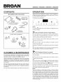 2
2
-
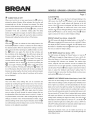 3
3
-
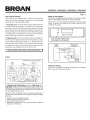 4
4
-
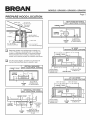 5
5
-
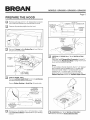 6
6
-
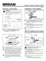 7
7
-
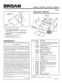 8
8
-
 9
9
-
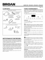 10
10
-
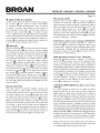 11
11
-
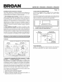 12
12
-
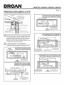 13
13
-
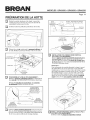 14
14
-
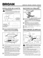 15
15
-
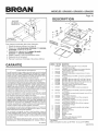 16
16
-
 17
17
-
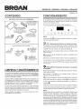 18
18
-
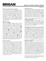 19
19
-
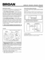 20
20
-
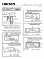 21
21
-
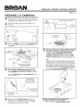 22
22
-
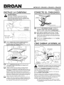 23
23
-
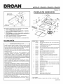 24
24


Broan QP430SS El manual del propietario
- Categoría
- Campanas de cocina
- Tipo
- El manual del propietario
en otros idiomas
- français: Broan QP430SS Le manuel du propriétaire
- English: Broan QP430SS Owner's manual
Artículos relacionados
-
Broan QP436SS Manual de usuario
-
Broan BPP3FA36 Guía de instalación
-
Broan QP330SS Manual de usuario
-
-
-
-
Broan QS236AA El manual del propietario
-
Broan QS342SS Manual de usuario
-
Broan QS330BC Manual de usuario
-