Troy-Bilt 17ARCBDW066 Manual de usuario
- Categoría
- Tractor
- Tipo
- Manual de usuario
Este manual también es adecuado para

TROY-BILT LLC, P.O. BOX 361131 CLEVELAND, OHIO 44136-0019
Printed In USA
OperatOr’s Manual
Safe Operation Practices • Set-Up • Operation • Maintenance • Service • Troubleshooting • Warranty
WARNING
READ AND FOLLOW ALL SAFETY RULES AND INSTRUCTIONS IN THIS MANUAL
BEFORE ATTEMPTING TO OPERATE THIS MACHINE.
FAILURE TO COMPLY WITH THESE INSTRUCTIONS MAY RESULT IN PERSONAL INJURY.
Pivot S
Form No. 769-11245
(October 28, 2015)

Customer Support
Please do NOT return the machine to the retailer or dealer without first contacting the Customer Support Department.
If you have difficulty assembling this product or have any questions regarding the controls, operation, or maintenance of
this machine, you can seek help from the experts. Choose from the options below:
◊ Visit us on the web at www.troybilt.com
See How-to Maintenance and Parts Installation Videos at www.troybilt.com/tutorials
◊ Call a Customer Support Representative at (800) 828-5500 or (330) 558-7220
◊ Write to Troy-Bilt LLC • P.O. Box 361131 • Cleveland, OH • 44136-0019
Thank you for purchasing a Troy-Bilt Zero-Turn Tractor. It was
carefully engineered to provide excellent performance when
properly operated and maintained.
Please read this entire manual prior to operating the equipment.
It instructs you how to safely and easily set up, operate and
maintain your machine. Please be sure that you, and any other
persons who will operate the machine, carefully follow the
recommended safety practices at all times. Failure to do so could
result in personal injury or property damage.
All information in this manual is relative to the most recent
product information available at the time of printing. Review
this manual frequently to familiarize yourself with the machine,
its features and operation. Please be aware that this Operator’s
Manual may cover a range of product specifications for various
models. Characteristics and features discussed and/or illustrated
in this manual may not be applicable to all models. We reserve
the right to change product specifications, designs and
equipment without notice and without incurring obligation.
If applicable, the power testing information used to establish
the power rating of the engine equipped on this machine can be
found at www.opei.org or the engine manufacturer’s web site.
If you have any problems or questions concerning the machine,
phone a authorized Troy-Bilt service dealer or contact us directly.
Troy-Bilt’s Customer Support telephone numbers, website
address and mailing address can be found on this page. We want
to ensure your complete satisfaction at all times.
Throughout this manual, all references to right and left side of the
machine are observed from the operating position
The engine manufacturer is responsible for all engine-related
issues with regards to performance, power-rating, specifications,
warranty and service. Please refer to the engine manufacturer’s
Owner’s/Operator’s Manual, packed separately with your
machine, for more information.
Thank You
Record Product Information
Before setting up and operating your new equipment, please
locate the model plate on the equipment and record the
information in the provided area to the right. You can locate the
model plate by standing at the left side of the tractor, pivoting
the seat forward and looking down at the seat frame. This
information will be necessary, should you seek technical support
via our web site, Customer Support Department, or with a local
authorized service dealer.
Model NuMber
Serial NuMber
To The Owner
1
2
Table of Contents
Safe Operation Practices ........................................ 3
Assembly & Set-Up .................................................. 9
Controls & Features ................................................ 13
Operation ................................................................16
Maintenance & Adjustment ................................ 20
Service .................................................................... 25
Troubleshooting .................................................... 30
Replacement Parts .................................................31
Attachments & Accessories .................................. 33
Warranties ............................................................. 34

Important Safe Operation Practices
2
3
General Operation
1. Read, understand, and follow all instructions on the
machine and in the manual(s) before attempting to
assemble and operate. Keep this manual in a safe place for
future and regular reference and for ordering replacement
parts.
2. Be familiar with all controls and their proper operation.
Know how to stop the machine and disengage them
quickly.
3. Never allow children under 14 years of age to operate this
machine. Children 14 and over should read and understand
the instructions and safe operation practices in this manual
and on the machine and should be trained and supervised
by an adult.
4. Never allow adults to operate this machine without proper
instruction.
5. To help avoid blade contact or a thrown object injury,
keep bystanders, helpers, children and pets at least 75 feet
from the machine while it is in operation. Stop machine if
anyone enters the area.
6. Thoroughly inspect the area where the equipment is to be
used. Remove all stones, sticks, wire, bones, toys, and other
foreign objects which could be picked up and thrown by
the blade(s). Thrown objects can cause serious personal
injury.
7. Plan your mowing pattern to avoid discharge of material
toward roads, sidewalks, bystanders and the like. Also,
avoid discharging material against a wall or obstruction
which may cause discharged material to ricochet back
toward the operator.
8. Always wear safety glasses or safety goggles during
operation and while performing an adjustment or repair
to protect your eyes. Thrown objects which ricochet can
cause serious injury to the eyes.
9. Wear sturdy, rough-soled work shoes and close-fitting
slacks and shirts. Loose fitting clothes and jewelry can be
caught in movable parts. Never operate this machine in
bare feet or sandals.
10. Be aware of the mower and attachment discharge direction
and do not point it at anyone. Do not operate the mower
without the discharge cover or entire grass catcher in its
proper place.
11. Do not put hands or feet near rotating parts or under the
cutting deck. Contact with the blade(s) can amputate
hands and feet.
WARNING! This symbol points out important safety instructions which, if not followed,
could endanger the personal safety and/or property of yourself and others. Read and follow
all instructions in this manual before attempting to operate this machine. Failure to comply
with these instructions may result in personal injury.
When you see this symbol. HEED ITS WARNING!
DANGER! This machine was built to be operated according to the safe operation practices in
this manual. As with any type of power equipment, carelessness or error on the part of the
operator can result in serious injury. This machine is capable of amputating hands and feet
and throwing objects. Failure to observe the following safety instructions could result in
serious injury or death.
CALIFORNIA PROPOSITION 65
WARNING! Engine Exhaust, some of its constituents, and certain vehicle components
contain or emit chemicals known to State of California to cause cancer and birth defects
or other reproductive harm.
WARNING! Battery posts, terminals, and related accessories contain lead and lead
compounds, chemicals known to the State of California to cause cancer and reproductive
harm. Wash hands after handling

4 Section 2 — important Safe operation practiceS
12. A missing or damaged discharge cover can cause blade
contact or thrown object injuries.
13. Stop the blade(s) when crossing gravel drives, walks, or
roads and while not cutting grass.
14. Watch for traffic when operating near or crossing
roadways. This machine is not intended for use on any
public roadway.
15. Do not operate the machine while under the influence of
alcohol or drugs.
16. Mow only in daylight or good artificial light.
17. Never carry passengers.
18. Back up slowly. Always look down and behind before and
while backing to avoid a back-over accident. Be aware
and pay attention to the safety system function that
stops power to the blades when driving in reverse. If not
fuctioning properly, contact an authorized dealer for safety
system inspection and repair.
19. Slow down before turning. Operate the machine smoothly.
Avoid erratic operation and excessive speed.
20. Disengage blade(s), set parking brake, stop engine and wait
until the blade(s) come to a complete stop before removing
grass catcher, emptying grass, unclogging chute, removing
any grass or debris, or making any adjustments.
21. Never leave a running machine unattended. Always turn off
blade(s), place drive control levers in neutral, set parking
brake, stop engine and remove key before dismounting.
22. Use extra care when loading or unloading the machine into
a trailer or truck. This machine should not be driven up or
down ramp(s), because the machine could tip over, causing
serious personal injury. The machine must be pushed
manually on ramp(s) to load or unload properly.
23. Muffler and engine become hot and can cause a burn. Do
not touch.
24. Check overhead clearances carefully before driving under
low hanging tree branches, wires, door openings etc.,
where the operator may be struck or pulled from the
machine, which could result in serious injury.
25. Disengage all attachment clutches, set the parking brake to
the ‘ON’ position.
26. Your machine is designed to cut normal residential grass of
a height no more than 10”. Do not attempt to mow through
unusually tall, dry grass (e.g., pasture) or piles of dry leaves.
Dry grass or leaves may contact the engine exhaust and/
or build up on the mower deck presenting a potential fire
hazard.
27. Use only accessories and attachments approved for this
machine by the machine manufacturer. Read, understand
and follow all instructions provided with the approved
accessory or attachment.
28. Data indicates that operators, age 60 years and above, are
involved in a large percentage of riding mower-related
injuries. These operators should evaluate their ability
to operate the riding mower safely enough to protect
themselves and others from serious injury.
29. If situations occur which are not covered in this manual, use
care and good judgment. Contact your customer service
representative for assistance.
Slope Operation
Slopes are a major factor related to loss of control and tip-over
accidents which can result in severe injury or death. All slopes
require extra caution. If you cannot back up the slope or if you
feel uneasy on it, do not mow it.
For your safety, use the slope gauge included as part of this
manual to measure slopes before operating this machine on
a sloped or hilly area. If the slope is greater than 15 degrees as
shown on the slope gauge, do not operate this machine on that
area or serious injury could result.
Do:
1. Mow across slopes, not up and down. Exercise extreme
caution when changing direction on slopes.
2. Watch for holes, ruts, bumps, rocks, or other hidden
objects. Uneven terrain could overturn the machine. Tall
grass can hide obstacles.
3. Use slow speed. Choose a low enough speed so that you
will not have to stop while on the slope. Avoid starting
or stopping on a slope. If the tires are unable to maintain
traction, disengage the blades and proceed slowly and
carefully straight down the slope.
4. Follow the manufacturer’s recommendations for wheel
weights or counterweights to improve stability.
5. Use extra care with grass catchers or other attachments.
These can change the stability of the machine.
6. Keep all movement on the slopes slow and gradual. Do
not make sudden changes in speed or direction. Rapid
acceleration or deceleration could cause the front of the
machine to lift and rapidly flip over backwards, which
could cause serious injury.
Do Not:
1. Do not turn on slopes unless necessary; then turn slowly
uphill and use extra care while turning.
2. Do not mow near drop-offs, ditches or embankments. The
mower could suddenly turn over if a wheel is over the edge
of a cliff, ditch, or if an edge caves in.
3. Do not try to stabilize the machine by putting your foot on
the ground.
4. Do not use a grass catcher on steep slopes.
5. Do not mow on wet grass. Reduced traction could cause
sliding.
6. Do not tow heavy pull behind attachments (e.g. loaded
dump cart, lawn roller, etc.) on slopes greater than 5
degrees. When going down hill, the extra weight tends to
push the tractor and may cause you to lose control (e.g.
tractor may speed up, braking and steering ability are
reduced, attachment may jack-knife and cause tractor to
overturn).

5Section 2 — important Safe operation practiceS
Children
1. Tragic accidents can occur if the operator is not alert to the
presence of children. Children are often attracted to the
machine and the mowing activity. They do not understand
the dangers. Never assume that children will remain where
you last saw them.
a. Keep children out of the mowing area and in
watchful care of a responsible adult other than the
operator.
b. Be alert and turn machine off if a child enters the
area.
c. To avoid back-over accidents, always look behind
and down for small children.
d. Never carry children, even with the blade(s) shut off.
They may fall off and be seriously injured or interfere
with safe machine operation.
e. Use extreme care when approaching blind corners,
doorways, shrubs, trees or other objects that may
block your vision of a child who may run into the
path of the machine.
f. Keep children away from hot or running engines.
They can suffer burns from a hot muffler.
g. Remove key when machine is unattended to
prevent unauthorized operation.
2. Never allow children under 14 years of age to operate this
machine. Children 14 and over should read and understand
the instructions and safe operation practices in this manual
and on the machine and should be trained and supervised
by an adult.
Towing
1. Tow only with a machine that has a hitch designed for
towing. Do not attach towed equipment except at the
hitch point.
2. Follow the manufacturers recommendation for weight
limits for towed equipment and towing on slopes.
3. Never allow children or others in or on towed equipment.
4. On slopes, the weight of the towed equipment may cause
loss of traction and loss of control.
5. The maximum weight on the hitch is 50 lbs. and the
maximum towed load is 250 lbs.
6. Never allow passengers on the towed equipment.
7. Loss of traction can occur on slopes, 5° (9 %) maximum
grade.
8. Travel slowly and allow extra distance to stop.
9. Use caution during turns to avoid jack-knifing.
10. Use extra caution when operating in reverse.
11. Do not modify or repair the hitch, replace the hitch if
damaged.
12. Travel slowly and allow extra distance to stop.
13. Do not shift to neutral and coast downhill.
Service
Safe Handling of Gasoline:
1. To avoid personal injury or property damage use extreme
care in handling gasoline. Gasoline is extremely
flammable and the vapors are explosive. Serious
personal injury can occur when gasoline is spilled on
yourself or your clothes which can ignite. Wash your skin
and change clothes immediately.
a. Use only an approved gasoline container.
b. Never fill containers inside a vehicle or on a truck
or trailer bed with a plastic liner. Always place
containers on the ground away from your vehicle
before filling.
c. When practical, remove gas-powered equipment
from the truck or trailer and refuel it on the ground.
If this is not possible, then refuel such equipment on
a trailer with a portable container, rather than from a
gasoline dispenser nozzle.
d. Keep the nozzle in contact with the rim of the fuel
tank or container opening at all times until fueling is
complete. Do not use a nozzle lock-open device.
e. Extinguish all cigarettes, cigars, pipes and other
sources of ignition.
f. Never fuel machine indoors.
g. Never remove gas cap or add fuel while the engine
is hot or running. Allow engine to cool at least two
minutes before refueling.
h. Never over fill fuel tank. Fill tank to no more than ½”
below bottom of filler neck to allow space for fuel
expansion.
i. Replace gasoline cap and tighten securely.
j. If gasoline is spilled, wipe it off the engine and
equipment. Move machine to another area. Wait 5
minutes before starting the engine.
k. To reduce fire hazards, keep machine free of grass,
leaves, or other debris build-up. Clean up oil or fuel
spillage and remove any fuel soaked debris.
l. Never store the machine or fuel container inside
where there is an open flame, spark or pilot light
as on a water heater, space heater, furnace, clothes
dryer or other gas appliances.
m. Allow a machine to cool at least five minutes before
storing.
General Service
1. Never run an engine indoors or in a poorly ventilated area.
Engine exhaust contains carbon monoxide, an odorless,
and deadly gas.
2. Before cleaning, repairing, or inspecting, make certain the
blade(s) and all moving parts have stopped. Disconnect
the spark plug wire(s) and ground against the engine to
prevent unintended starting.

6 Section 2 — important Safe operation practiceS
3. Periodically check to make sure the blades come to
complete stop within approximately (5) five seconds after
operating the blade disengagement control. If the blades
do not stop within the this time frame, your machine
should be serviced professionally by an authorized dealer.
4. Regularly check the safety interlock system for proper
function, as described later in this manual. If the safety
interlock system does not function properly, have your
machine serviced professionally by an authorized dealer.
5. Check the blade(s) and engine mounting bolts at frequent
intervals for proper tightness. Also, visually inspect blade(s)
for damage (e.g., excessive wear, bent, cracked). Replace
the blade(s) with the original equipment manufacturer’s
(O.E.M.) blade(s) only, listed in this manual. “Use of parts
which do not meet the original equipment specifications
may lead to improper performance and compromise
safety!”
6. Mower blades are sharp. Wrap the blade or wear gloves,
and use extra caution when servicing them.
7. Keep all nuts, bolts, and screws tight to be sure the
equipment is in safe working condition.
8. Never tamper with the safety interlock system or other
safety devices. Check their proper operation regularly.
9. After striking a foreign object, stop the engine, disconnect
the spark plug wire(s) and ground against the engine.
Thoroughly inspect the machine for any damage. Repair
the damage before starting and operating.
10. Never attempt to make adjustments or repairs to the
machine while the engine is running.
11. Grass catcher components and the discharge cover are
subject to wear and damage which could expose moving
parts or allow objects to be thrown. For safety protection,
frequently check components and replace immediately
with original equipment manufacturer’s (O.E.M.) parts only,
listed in this manual. “Use of parts which do not meet the
original equipment specifications may lead to improper
performance and compromise safety!”
12. Do not change the engine governor settings or over-speed
the engine. The governor controls the maximum safe
operating speed of the engine.
13. Maintain or replace safety and instruction labels, as necessary.
14. Observe proper disposal laws and regulations for gas, oil,
etc. to protect the environment.
15. According to the Consumer Products Safety Commission
(CPSC) and the U.S. Environmental Protection Agency (EPA),
this product has an Average Useful Life of seven (7) years,
or 270 hours of operation. At the end of the Average Useful
Life have the machine inspected annually by an authorized
service dealer to ensure that all mechanical and safety
systems are working properly and not worn excessively.
Failure to do so can result in accidents, injuries or death.
Do not modify engine
To avoid serious injury or death, do not modify engine in any
way. Tampering with the governor setting can lead to a runaway
engine and cause it to operate at unsafe speeds. Never tamper
with factory setting of engine governor.
Notice Regarding Emissions
Engines which are certified to comply with California and federal
EPA emission regulations for SORE (Small Off Road Equipment)
are certified to operate on regular unleaded gasoline, and
may include the following emission control systems: Engine
Modification (EM) and Three Way Catalyst (TWC) if so equipped.
When required, models are equipped with low permeation fuel
lines and fuel tanks for evaporative emission control. California
models may also include a carbon canister. Please contact
Customer Support for information regarding the evaporative
emission control configuration for your model.
Spark Arrestor
WARNING! This machine is equipped with an
internal combustion engine and should not be used
on or near any unimproved forest-covered, brush-
covered or grass-covered land unless the engine’s
exhaust system is equipped with a spark arrestor
meeting applicable local or state laws (if any).
If a spark arrestor is used, it should be maintained in
effective working order by the operator. In the State of California
the above is required by law (Section 4442 of the California Public
Resources Code). Other states may have similar laws. Federal laws
apply on federal lands.
A spark arrestor for the muffler is available through your
nearest engine authorized service dealer or contact the service
department, P.O. Box 361131 Cleveland, Ohio 44136-0019.
WARNING! Your Responsibility — Restrict the use of this power machine to persons who read, understand and
follow the warnings and instructions in this manual and on the machine.
SAVE THESE INSTRUCTIONS!

7Section 2 — important Safe operation practiceS
Safety Symbols
This page depicts and describes safety symbols that may appear on this product. Read, understand, and follow all instructions on the
machine before attempting to assemble and operate.
Symbol Description
READ THE OPERATOR’S MANUAL(S)
Read, understand, and follow all instructions in the manual(s) before attempting to
assemble and operate
DANGER — ROTATING BLADES
Never carry passengers. Never carry children, even with the blades off.
DANGER — ROTATING BLADES
Mowing in reverse is not recommended.
WARNING — ROTATING BLADES
Do not put hands or feet near rotating parts or under the cutting deck. Contact with the
blade(s) can amputate hands and feet.
DANGER — ROTATING BLADES
Look down and behind before and while backing to avoid a back-over accident.
WARNING — THROWN OBJECTS
This machine may pick up and throw and objects which can cause serious personal injury.
DANGER — SAFETY DEVICES
Keep safety devices (guards, shields, switches, etc.) in place and working.
WARNING — BYSTANDERS
Keep bystanders, helpers, children and pets at least 75 feet from the machine while it is in
operation.
WARNING — SLOPE OPERATION
Do not operate this machine on a slope greater than 15 degrees. Do not mow up and down
slopes. Mow across slopes no greater than 15 degrees. Avoid sudden turns. Use low speed. If
machine stops going uphill, stop blades and back down slowly.
WARNING — HOT SURFACE
Engine parts, especially the muffler, become extremely hot during operation. Allow engine
and muffler to cool before touching.
DANGER — ROTATING BLADES
To reduce the risk of injury, keep hands and feet away. Do not operate unless discharge cover
or grass catcher is in its proper place. If damaged, replace immediately.
WARNING — FIRE HAZARD
Allow machine to cool before fueling or storing.
max10"
WARNING — FIRE HAZARD
Do not drive through piles of dry leaves or tall grass.
WARNING — FIRE HAZARD
Do not allow debris to accumulate. The build up of debris can lead to a fire.

8 Section 2 — Safe operation practiceS
WARNING! Slopes are a major factor related to tip-over and roll-over accidents which can result in severe injury or death.
Do not operate machine on slopes in excess of 15 degrees. All slopes require extra caution.
Always mow across the face of slopes, never up and down slopes.

Assembly & Set-Up
3
9
Contents of Crate
• One Lawn Tractor • One Deck Wash Hose Coupler • One Operator’s Manual
• One Engine Operator’s Manual • Two Hex Screws and Flat Washers
Tractor Preparation
1. Remove the upper crating material from the shipping pallet,
and cut any bands or tie straps securing the tractor to the
pallet.
2. If the deck is not in the highest mowing position (pulled all
the way back), use the deck lift handle to raise the deck to its
highest position. Refer to the Controls & Features section for
instructions on raising and lowering the deck.
3. Disengage the parking brake.
4. Engage the transmission bypass rods on each side of the
tractor; then carefully roll the tractor off the shipping pallet.
The transmission bypass rods (one for each the RH and LH
transmission) are located on the rear of the tractor, just
inside each rear wheel. Engage the bypass rods by pulling
each one out and to the right then letting it return to lock it
into place. See Figure 3-1.
a
a
b
Figure 3-1
5. Disengage the bypass rods after rolling the tractor off the
pallet. See Figure 3-1.
6. Remove the deck wash system nozzle adapter from the
manual bag and store for future use.
Steering Wheel Column
The steering wheel column is tilted all the way back for shipping.
1. Place the steering column in one of the two positions and
secure in place with the hex screws and flat washers packed
seperately. See Figure 3-2.
Hex Screw
Flat Washer
Figure 3-2
Steering Wheel
1. Remove the hardware for attaching the steering wheel
from beneath the steering wheel cap. Carefully pry off the
steering wheel cover to remove the hardware.
2. With the wheels of the tractor pointing straight forward,
place the steering wheel over the steering shaft.

10 Section 3— ASSembly & Set-Up
3. Place the flat washer and belleville washer over the steering
wheel and secure with the hex screw. See Figure 3-3.
Steering Wheel Cover
Hex Screw
Steering Wheel
Steering Wheel
Column
Belleville Washer
Figure 3-3
4. Place the steering wheel cover over the center of the steering
wheel and push downward until it “clicks” into place.
Install Operator’s Seat
To install the seat proceed as follows:
NOTE: The seat is shipped with the seat switch and seat
pan attached.
1. Cut any straps securing the seat assembly and the drive
control levers to the tractor. Remove any packing material.
NOTE: Be careful not to cut the wiring harness connecting
the seat and the seat switch.
2. Remove the two shoulder screws and flange lock nuts in
the seat pan as shown in Figure 3-4.
Shoulder Screws
Flange Lock Nuts
Wire
Harness
Seat
Pan
Clamp Knob Clamp Knob
Figure 3-4
3. Rotate the seat into position and secure the seat into place
with the previously removed shoulder screws and flange
lock nuts. Be careful not to crimp or damage the wire
harness while installing the seat. See Figure 3-4.
NOTE: Be sure to push the excess wire from the wire
harness into the seat box hole before continuing.
Lower Deck Discharge Chute Deflector
WARNING! Never operate the mower deck
without the chute deflector installed and in the
down position.
NOTE: For models with a 46”, 50” and 54” Deck skip ahead
to step 6.
1. Remove the keys that are attached with a zip tie to the
chute bracket.
2. Remove the flange lock nut and hex screw from the deck.
3. Place the chute deflector on the deck, be sure to insert the
tabs on the chute deflector into the holes on the deck. See
Figure 3-5.
3
4
5
5
4
Figure 3-5
4. When the tabs are installed in the deck, slide the chute
deflector toward the rear of the tractor until the bolt hole
in the chute deflector aligns with the hole in the deck. See
Figure 3-5.
5. Secure the chute deflector in place with the flange lock
nut and hex screw removed in step 2. Tighten to 102-124
in-lbs. See Figure 3-5.

11Section 3 — ASSembly & Set-Up
Setting the Front Gauge Wheels
WARNING! Keep hands and feet away from the
discharge opening of the cutting deck.
NOTE: The deck wheels are an anti-scalp feature of the deck and
are not designed to support the weight of the cutting deck.
Move the tractor on a firm and level surface, preferably pavement,
and proceed as follows:
1. Check the tire pressure, make sure the pressure is correct
and equal on all tires.
2. Make sure the deck is level, both front-to-back and side-to-
side. See the Maintenance & Adjustments section for deck
leveling information and instructions.
3. Select the height position of the cutting deck by placing the
deck lift lever in the normally desired mowing height setting.
4. Check the wheels for contact or excessive clearance with
the surface below. The deck wheels should have between
¼” and ½” clearance above the ground. Proceed as follows
to adjust the wheels:
a. Remove the lock nut securing one of the front gauge
wheel shoulder screws to the deck. Remove the
gauge wheel and shoulder screw. See Figure 3-7.
Lock
Nut
Front Gauge
Wheel
Shoulder
Screw
Gauge Wheel
Bracket
Index Holes
Figure 3-7
b. Insert the shoulder screw into the one of four index
holes in the front gauge wheel bracket that will give
the gauge wheel a ⁄⁄” clearance with the ground.
c. Note the index hole of the just adjusted wheel, and
adjust the other front gauge wheel into the respective
index hole of the other front gauge wheel bracket.
NOTE: Refer to Adjusting the Deck in the Maintenance
& Adjustments section of this manual for more detailed
instructions regarding various deck adjustments.
6. On models with a 46”, 50” and 54” decks the chute is
shipped attached and with a stop bracket holding the
chute upright. The stop brackets must be removed prior to
operating the tractor.
7. Holding the chute deflector fully upward, remove the
shipping brace. Lower the chute deflector and discard the
shipping brace. See Figure 3-6.
Figure 3-6

12 Section 3— ASSembly & Set-Up
Connecting the Battery Cables
CALIFORNIA PROPOSITION 65 WARNING!
Battery posts, terminals, and related accessories
contain lead and lead compounds, chemicals known
to the State of California to cause cancer and
reproductive harm. Wash hands after handling.
CAUTION: When attaching battery cables, always
connect the POSITIVE (Red) wire to its terminal first,
followed by the NEGATIVE (Black) wire.
For shipping reasons, both battery cables on your equipment
may have been left disconnected from the terminals at the
factory. To connect the battery cables, proceed as follows:
NOTE: The positive battery terminal is marked Pos. (+). The
negative battery terminal is marked Neg. (–).
NOTE: If the positive battery cable is already attached, skip
ahead to step 2.
1. Remove the plastic cover, if present, from the positive
battery terminal and attach the red cable to the positive
battery terminal (+) with the bolt and hex nut. See Figure
3-8.
Figure 3-8
2. Remove the plastic cover, if present, from the negative battery
terminal and attach the black cable to the negative battery
terminal (–) with the bolt and hex nut. See Figure 3-8.
3. Position the red rubber boot over the positive battery
terminal to help protect it from corrosion.
NOTE: If the battery is put into service after the date shown
on top/side of battery, charge the battery as instructed in
the Maintenance section your Operator’s Manual prior to
operating the tractor.
Adjusting the Seat
To adjust the position of the seat, rotate the seat forward and locate
the clamp knobs on the front of the seat pan. Refer to Figure 3-4.
Rotate the clamp knobs to the left and remove them, slide the
seat forward or backward and re-insert the clamp knobs into
one of the four available positions on the seat pan and into the
seat, then tighten both securely. Make sure the seat is locked into
position before operating the tractor. See Figure 3-9.
Clamp
Knob
Seat
Adjustment
Positions
Figure 3-9
Fuel Fill-Up
Using a good grade of unleaded regular gasoline, fill the tank
(beside the engine on the left side of the mower). When the fuel
tank reaches one inch from the top of the tank, stop, DO NOT
OVERFILL. Space must be left for expansion.

Controls & Features
4
13
Ignition Switch
Module
Throttle/Choke Control
Forward Drive Pedal
Reverse Drive Pedal
Deck Lift Handle
Deck Height Index
LCD Service Minder & Hour Meter
Parking Brake/Cruise Control Lever
Steering Wheel
Fuel Tank Cap
Brake Pedal
Transmission Bypass ValvesTransmission Bypass Valves
Cup Holder
Storage Tray
PTO Knob
NOTE: References to LEFT, RIGHT, FRONT, and REAR indicate that
position on the tractor when facing forward while seated in the
operator’s seat.
Deck Height Index
The deck height index consists of eight
index notches located on the front/right
of the console. Each notch corresponds to
a ⁄” change in the deck height position
ranging from 1-⁄” at the lowest notch to
4” at the highest notch.
Deck Lift Handle
The deck lift handle is located on the front/
right of the console, and is used to raise and
lower the mower deck.
Pull the handle to the left out of the index
notch and push downward to lower the
deck, or pull upward to raise the deck.
When the desired height is attained, move
the lift handle to the right until fully in the
index notch.
Cup Holder
The cup holder is located on the RH console to the right of the
operator’s seat.
Storage Tray
The storage tray is located at the rear of the RH console.
Seat Clamp Knob (Not Seen)
The seat clamp knob is located below the front/left of the seat.
The knob allows for adjustment forward or backward of the
operator’s seat. Refer to the Assembly & Set-Up section for
instructions on adjusting the seat position.

14 Section 4— controlS & FeatureS
Ignition Switch Module
WARNING! Never
leave a running
machine unattended.
Always disengage PTO,
set parking brake, stop
engine and remove key
to prevent unintended
starting.
To start the engine, insert the key
into the ignition switch and turn
clockwise to the START position.
Release the key into the NORMAL MOWING MODE position
once the engine has fired.
To stop the engine, turn the ignition key counterclockwise to the
STOP position.
CAUTION: Prior to operating the tractor, refer to
both Safety Interlock Switches and Starting The
Engine in the Operation section of this manual for
detailed instructions regarding the Ignition Switch
Module and operating the tractor in REVERSE
CAUTION MODE .
PTO Knob
The PTO (Power Take-Off) knob is located on the
RH console to the right of the operator’s seat.
The PTO knob operates the electric PTO
clutch mounted on the bottom of the engine
crankshaft. Pull the knob upward to engage
the PTO clutch, or push the knob downward to
disengage the clutch.
The PTO knob must be in the “disengaged”
position when starting the engine.
Fuel Tank Cap
The fuel tank cap is located on the left console. Turn the fill cap
to remove. Always re-install the fuel cap tightly onto the fuel tank
after removing.
WARNING! Never fill the fuel tank when the
engine is running. If the engine is hot from recently
running, allow to cool for several minutes before
refueling. Highly flammable gasoline could splash
onto the engine and cause a fire.
Throttle/Choke Control
The throttle/choke control is located on the RH console
to the left of the hour meter/indicator panel. When
set in a given position, a uniform engine speed will be
maintained.
• Push the throttle/choke control handle forward to
increase the engine speed. The tractor is designed
to operate with the throttle/choke control in the
fast position (full throttle) when the tractor is being
driven and the mower deck is engaged.
• Pull the throttle/choke control handle rearward to
decrease the engine speed.
• When starting the engine, push the control handle fully
forward into the “CHOKE” position.
• After starting and warming the engine, move the control
handle rearward until you feel it move past the choke
detent.
Forward Drive Pedal
The forward drive pedal is located on the right side
of the tractor, along the running board. Press the
forward drive pedal forward to cause the tractor to
travel forward. Ground speed is also controlled with
the forward drive pedal. The further forward the
pedal is pivoted, the faster the tractor will travel. The
pedal will return to its original position when it’s not
pressed.
Reverse Pedal
The reverse drive pedal is located on the right side of
the tractor along the running board. Ground speed
is also controlled with the reverse drive pedal. The
further downward the pedal is pivoted, the faster the
tractor will travel. The pedal will return to its original
position when it’s not pressed.
Transmission Bypass Valves
The transmission bypass valves (one for each the RH and LH
transmission) are located under the tractor on the back of each
transmission inside the rear wheels.
When engaged, the two valves open a bypass within the
hydrostatic transmissions, which allows the tractor to be pushed
short distances by hand. Refer to the Assembly & Set-Up section
for instructions on using the bypass feature.
FAST
SL
OW

15Section 4 — controlS & FeatureS
Park Brake/
Cruise Control Lock Pedal
The park brake/cruise control lock pedal is
located at the base of the steering column.
It is used to engage the park brake when the
tractor is at rest. Engaging the lever while the
tractor is in motion allows the tractor to remain
at a constant ground speed without applying
pressure to the forward drive pedal. Refer to the
Operation section of this manual for detailed
instructions regarding the parking brake as well
as the cruise control feature.
NOTE: Cruise control can NOT be engaged
at the tractor’s fastest ground speed. If the
operator should attempt to do so, the tractor will
automatically decelerate to the fastest optimal
mowing ground speed
NOTE: The park brake must be set if the operator
leaves the seat with the engine running or the
engine will automatically shut off.
WARNING! Never leave a running
machine unattended. Always disengage PTO, set
parking brake, stop engine and remove key to
prevent unintended starting.
Hour Meter
LCD Service Minder & Hour Meter
When the ignition key is rotated
out of the STOP position but
not into the START position, the
LCD Service Minder and Hour
Meter will briefly display the
battery voltage, followed by the
tractor’s accumulated hours.
NOTE: Hours of tractor operation
are recorded any time the ignition
key is rotated out of the STOP
position, regardless of whether
the engine is started.
The LCD Service Minder will remind the operator of maintenance
intervals for changing the engine oil, air filter service, low engine
and low battery warnings.
P
A
R
K
B
R
A
K
E
CRUISE
CONTROL
Change Oil
The LCD will display the letters “CHG”, followed by the letters
“OIL”, followed by the letters “SOON”, then finally followed by the
meter’s accumulated time. “CHG/OIL/SOON/TIME” will alternate
on the display for 7 minutes after the meter reaches 50 hours.
This oil service minder interval will occur every 50 hours. Before
the interval expires, change the engine oil as instructed in the
Maintenance section of the Engine Operator’s Manual
Low Oil
The letters “LO” followed by the letters “OIL”, then followed by
the meter’s accumulated time will indicate the tractor is low on
oil. When an engine is not running and immediately after the
engine is started the oil pressure may be low. This can trigger the
“LO” “OIL” text. This is normal. If the low oil indication persists
stop the tractor immediately and check the engine oil level as
instructed in the Engine Operator’s Manual.
NOTE: The “LOW OIL” function only works if the engine is
equipped with an oil pressure switch.
Low Battery
At startup, the battery voltage is briefly displayed then changes
to accumulated hours. The letters “LO” will display followed by
the letters “BATT” and then followed by the meter’s accumulated
time. “LO/BATT/TIME” is displayed on the LCD when the voltage
drops below 11.5 volts. When this occurs, the battery is in need
of a charge or the engine’s charging system is not generating
sufficient amperage. Charge the battery as instructed in the
Service section of this manual or have the charging system
checked by your local service dealer.
Air Filter Service
The letters “CLN” will display, followed by the letters “AIR”,
followed by “FILT”, then followed by the meter’s accumulated
time. “CLN/AIR/FILT/TIME” will alternate on the display for 7
minutes after the meter reaches 25 hours. This air filter service
minder time interval will be every 25 hours. On intervals that are
common with oil service, the oil message will be displayed first
followed by the air filter message.

Operation
5
16
General Safety
• RECEIVE INSTRUCTION — Entirely read this operator’s
manual. Learn to operate this machine SAFELY. Do not risk
INJURY or DEATH. Allow only those who have become
competent in its usage to operate this tractor.
• Before starting the engine or beginning operation, be
familiar with the controls. The operator should be in the
operator’s seat. The PTO switch must be in the disengaged
position and the parking brake engaged.
• Keep all shields in place. Keep away from moving parts.
• NO RIDERS! Keep all people and pets a safe distance away.
Look behind and down to both sides of the tractor before
and while backing up.
• DO NOT direct the mower discharge at people.
• Avoid slopes where possible. Never operate on slopes
greater than 15°. Slopes with a greater incline present
dangerous operating conditions. Tractors can be rolled over.
• Before leaving the operator’s seat shut off the PTO and
engage the parking brake, shut off the engine and remove
the ignition key. Wait for all movement to stop before
servicing or cleaning.
• Avoid any sudden movements of the steering wheel when
starting and stopping. Keep a firm grip on the steering wheel.
• Be careful when operating near roadways. Stop the tractor
motion and wait for vehicles to pass before operating
along the road.
• Do not operate the tractor with the mower deck removed.
Removal of the deck will change the balance of the tractor,
and could contribute to a tractor rollover.
• Avoid operation on traction surfaces that are unstable; use
extreme caution if the surface is slippery.
• Slow down before turning and come to a complete stop
before any zero turn maneuver.
• Do not stop the tractor or park the tractor over
combustible materials such as dry grass, leaves, debris, etc.
• Do not fill the fuel tank when the engine is running or
while the engine is hot. Allow the engine several minutes
to cool before refueling. Tighten the fuel cap securely.
Before Operating Your Tractor
• Before you operate the tractor, study this manual carefully
to familiarize yourself with the operation of all the
instruments and controls. It has been prepared to help you
operate and maintain your tractor efficiently.
• This engine is certified to operate only on clean, fresh,
unleaded regular gasoline. For best results, fill the fuel
tank with only clean, fresh, unleaded gasoline with a pump
sticker octane rating of 87 or higher.
• Unleaded gasoline is recommended because it leaves
less combustion chamber deposits and reduces harmful
exhaust emissions. Leaded gasoline is not recommended
and must not be used where exhaust emissions are
regulated.
NOTE: Purchase gasoline in small quantities. Do not use
gasoline left over from the previous season, to minimize
gum deposits in the fuel system.
• Gasohol (up to 10% ethyl alcohol, 90% unleaded gasoline
by volume) is an approved fuel. Other gasoline/alcohol
blends are not approved.
• Methyl Tertiary Butyl Ether (MTBE) and unleaded gasoline
blends (up to a maximum of 15% MTBE by volume) are
approved fuels. Other gasoline/ether blends are not
approved.
• Check the engine oil level.
• Clean the air cleaner element if necessary.
• Check the tire inflation pressures.
• Adjust the seat for operator’s maximum comfort, visibility
and for maintaining complete control of the tractor.
Safety Interlock Switches
This tractor is equipped with a safety interlock system for the
protection of the operator. If the interlock system should ever
malfunction, do not operate the tractor. Contact your authorized
service dealer.
• The safety interlock system prevents the engine from
cranking or starting unless the parking brake is engaged,
and the PTO knob is in the disengaged (OFF) position.
• The engine will automatically shut off if the operator leaves
the seat before engaging the parking brake.
WARNING! Do not operate the tractor if the
interlock system is malfunctioning. This system was
designed for your safety and protection.

Section 5 — operation 17
Starting the Engine
WARNING! This tractor is equipped with a safety
interlock system designed for the protection of the
operator. Do not operate the tractor if any part of the
system is malfunctioning. Periodically check the
function of the interlock system for proper operation.
WARNING! For personal safety, the operator must
be sitting in the tractor seat when starting the
engine.
NOTE: Refer to the Engine Operator’s Manual for oil fill-up
instructions and refer to the Assembly & Set-Up section for
gasoline fill-up instructions.
1. Operator must be sitting in the tractor seat.
2. Engage the parking brake by pressing forward on the brake
pedal , then press down on the parking break/cruise
control lever and then release the brake pedal . Refer to
Figure 5-1.
Brake Pedal
Parking Brake/Cruise Control Lever
Figure 5-1
3. Make certain the PTO switch is in the disengaged (down)
position. Refer to Figure 5-1.
4. Move the throttle/choke control (if equipped) into the
CHOKE position.
NOTE: If the engine is warmed up, it may not be necessary to
CHOKE the engine.
5. Turn the ignition key clockwise to the START position.
After the engine starts, release the key. It will return to the
run position.
CAUTION: Do NOT hold the key in the START
position for longer than ten seconds at a time. Doing
so may cause damage to your engine’s electric
starter.
6. As the engine warms up, gradually pull the throttle/choke
control lever (if equipped) rearward past the choke detent
position or push the choke knob (if equipped) down into
the OFF position.
NOTE: Do NOT leave the throttle/choke control in the CHOKE
position while operating the tractor. Doing so will result
in a “rich” fuel mixture and cause the engine to run poorly.
7. Allow the engine to run for a few minutes at mid throttle
before putting the engine under load.
8. Observe the hour meter/indicator panel. If the battery indicator
light or oil pressure light come on, immediately stop the engine.
Have the tractor inspected by your authorized service dealer.
Cold Weather Starting
When starting the engine at temperatures near or below freezing,
ensure the correct viscosity motor oil is used in the engine and the
battery is fully charged. Start the engine as follows:
1. Be sure the battery is in good condition. A warm battery
has much more starting capacity than a cold battery.
2. Use fresh winter grade fuel. Winter grade gasoline has
higher volatility to improve starting. Do not use gasoline
left over from summer.
3. Follow the previous instruction for Starting the Engine.
Using Jumper Cables To Start Engine
WARNING! Batteries contain sulfuric acid and
produce explosive gasses. Make certain the area is
well ventilated, wear gloves and eye protection, and
avoid sparks or flames near the battery.
If the battery charge is not sufficient to crank the engine,
recharge the battery. If a battery charger is unavailable and
the tractor must be started, the aid of a booster battery will be
necessary. Connect the booster battery as follows:
1. Connect the end of one cable to the disabled tractor
battery’s positive terminal; then connect the other end of
that cable to the booster battery’s positive terminal.
2. Connect one end of the other cable to the booster
battery’s negative terminal; then connect the other end of
that cable to the frame of the disabled tractor, as far from
the battery as possible.
3. Start the disabled tractor following the normal starting
instructions previously provided; then disconnect the
jumper cables in the exact reverse order of their connection.
4. Have the tractor’s electrical system checked and repaired
as soon as possible to eliminate the need for jump starting.
Stopping the Engine
1. Place the PTO switch in the disengaged position.
2. Engage the parking brake.
3. Move the throttle/choke control to the SLOW position
and allow the engine to idle for about one minute.
4. Turn the ignition key to the STOP position and remove
the key from the ignition switch.
NOTE: Always remove the key from the ignition switch
to prevent accidental starting or battery discharge if the
equipment is left unattended.

Section 5— operation18
Driving The Tractor
WARNING! Avoid sudden starts, excessive speed
and sudden stops.
1. Release the parking brake. Move the throttle/choke control
lever into the FAST position.
2. To travel FORWARD, slowly press the forward drive pedal
forward until the desired speed is achieved. See Figure 5-2.
Forward Drive Pedal
Reverse Drive Pedal
Parking Brake/Cruise Control Lever
Figure 5-2
3. To stop or slow down the tractor, take your foot off of the
forward or reverse drive pedal . To lock the parking
brake, press forward on the brake pedal, then press down
on the parking break/cruise control lever and then release
the brake pedal .
4. To use the cruise control:
a. Press down on the forward drive pedal .
b. While maintaining the desired speed press down on
the parking break/cruise control lever then release
the forward drive pedal to activate the cruise
control.
5. To release the cruise control, press the brake or the
forward drive pedal .
NOTE: The forward and reverse drive pedals must not
be used when the brake is partially engaged. When the
brake is locked the drive belt is disengaged but if the brake
is only part way back then the brakes are engaged but so
is the drive belt so transmission damage will occur if you
push forward or reverse.
6. To travel in reverse, check that the area behind is clear then
slowly push forward on the reverse drive pedal with the
ball of your foot (NOT your heel) until the desired speed is
achieved. See Figure 5-2.
CAUTION: Do NOT attempt to change the
direction of travel when the tractor is in motion.
Always bring the tractor to a complete stop before
moving the tractor from forward to reverse or vice
versa.
WARNING! Do not leave the seat of the tractor
without first placing the PTO knob in the
disengaged (OFF) position and engaging the
parking brake. If leaving the tractor unattended, also
turn the engine off and remove the ignition key.
Reverse Caution Mode
The REVERSE CAUTION MODE position of the ignition
switch module allows the tractor to be operated in reverse with
the blades (PTO) engaged.
NOTE: Mowing in reverse is not recommended.
WARNING! Use extreme caution while operating
the tractor in the REVERSE CAUTION MODE .
Always look down and behind before and while
backing. Do not operate the tractor when children
or others are around. Stop the tractor immediately if
someone enters the area.
To use the REVERSE CAUTION MODE :
NOTE: The operator MUST be seated in the tractor seat.
1. Start the engine as instructed on the previous page.
2. Turn the key from the NORMAL MOWING (Green)
position to the REVERSE CAUTION MODE (Yellow)
position of the key switch module. See Figure 5-3.
Indicator
Light
Reverse
Push Button
Stop
Position
Start
Position
Reverse
Caution Mode
Position
Figure 5-3

Section 5 — operation 19
3. Press the REVERSE PUSH BUTTON (Orange, Triangular
Button) at the top, right corner of the key switch module.
The red indicator light at the top, left corner of the key
switch module will be ON while activated. See Figure 5-3.
4. Once activated (indicator light ON), the tractor can be
driven in reverse with the cutting blades (PTO) engaged.
5. Always look down and behind before and while backing to
make sure no children are around. After resuming forward
motion, return the key to the NORMAL MOWING
position.
The REVERSE CAUTION MODE will remain activated until:
a. The key is placed in either the NORMAL MOWING
position or STOP position or
b. The operator leaves the seat.
Driving On Slopes
Refer to the SLOPE GAUGE on page 8 to help determine slopes
where you may operate the tractor safely.
WARNING! Do not mow on inclines with a slope in
excess of 15 degrees (a rise of approximately 2-⁄
feet every 10 feet). The tractor could overturn and
cause serious injury.
• Mow across slopes, not up and down.
• Exercise extreme caution when changing direction on
slopes.
• Watch for holes, ruts, bumps, rocks, or other hidden
objects. Uneven terrain could overturn the machine. Tall
grass can hide obstacles.
• Do not turn on slopes unless necessary; then turn slowly
uphill and use extra care while turning. Turning up a slope
greatly increases the chance of a rollover.
• Avoid stopping when driving up a slope. If it is necessary
to stop while driving up a slope, start up smoothly and
carefully to reduce the possibility of flipping the tractor
over backward.
Mowing
WARNING! To help avoid blade contact or a
thrown object injury, keep bystanders, helpers,
children and pets at least 75 feet from the machine
while it is in operation. Stop machine if anyone
enters the area.
The following information will be helpful when using the cutting
deck with your tractor.
WARNING! Plan your mowing pattern to avoid
discharge of materials toward roads, sidewalks,
bystanders and the like. Also, avoid discharging
material against a wall or obstruction which may
cause discharged material to ricochet back toward
the operator.
• Do not mow at high ground speed, especially if a mulch kit
or grass collector is installed.
• Do not cut the grass too short. Short grass is prone to weed
growth and yellows quickly in dry weather.
• Always operate the tractor with the throttle in the FAST
position while mowing.
• For best results it is recommended that the first two laps be
cut with the discharge thrown towards the center. After the
first two laps, reverse the direction to throw the discharge
to the outside for the balance of cutting. This will give a
better appearance to the lawn.
• Do NOT attempt to mow heavy brush and weeds or
extremely tall grass. Your tractor is designed to mow lawns,
NOT clear brush.
• Keep the blades sharp and replace the blades when worn.
Manual Lift Lever
To raise or lower the cutting deck, move the lift lever to the left,
then place it in the notch best suited for your application.
Engaging the PTO
Engaging the PTO transfers power to the cutting deck or other
(separately available) attachments. To engage the PTO:
1. Move the throttle to the FAST position.
2. Pull the PTO/Blade Engage knob outward into the engaged
(ON) position. See Figure 5-4.
ON
OFF
Figure 5-4
NOTE: Always operate the tractor with the throttle lever
in the FAST position for the most efficient use of the
cutting deck or other (separately available) attachments.

Maintenance & Adjustments
6
20
Maintenance Schedule
Before
Each use
After First
5 Hours
Every 10
Hours
Every 25
Hours
Every 50
Hours
Every 100
Hours
Prior to
Storing
See
Engine
Manual
Check & Clean Engine Cooling Fans for Debris
P P
Check Engine Oil Level
P
Check Air Filter for Dirty, Loose or Damaged Parts
P
Clean Battery Terminals
P P
Grease All Lubrication Points
P P
Check Intake Screen/Clean as Needed
P P
Check Blades/Sharpen or Replace as Needed
P P
Check Tire Pressure
P P
Check/Clean Underside of Deck
P
Grease Front Castings
P
Lube Front Caster Wheels and Wheel Spindles
P P
Inspect & Lube Deck Wheels
P P
Check Deck Level/Pitch
P P
Check Belts & Pulleys for Damage/Wear
P
Check That All Hardware is in Place & Secure
P
Check &Clean Under Floorboard
P
Check Spark Plug Condition & Gap
P P P
Engine Break-In Oil Change
P P
Change Engine Oil
P P P
Replace Oil Filter
P P P
Clean or Change Air Filter
P P
Replace Fuel Filter
P P
Have Valve Lash Checked & Adjusted *
P
* -- Have this item performed by an authorized service dealer

Section 6 — Maintenance & adjuStMentS
21
NOTE: This Operator’s Manual covers several models. Tractor
features may vary by model. Not all features in this manual are
applicable to all tractor models and the tractor depicted may
differ from yours.
WARNING! Before performing any maintenance or
repairs, disengage PTO, set parking brake, stop engine
and remove key to prevent unintended starting.
Engine
Refer to the engine operator’s manual for all engine maintenance
procedures and instructions.
NOTE: Maintenance, repair, or replacement of the emission
control devices and systems which are being done at
owner’s expense may be performed by any engine repair
establishment or individual. Warranty repairs must be
performed by an authorized service dealer.
Changing the Engine Oil
WARNING! If the engine has been recently run, the
engine, muffler and surrounding metal surfaces will
be hot and can cause burns to the skin. Exercise
caution to avoid burns.
To complete an oil change, proceed as follows:
1. Run the engine for a short time to warm the engine oil. The
oil will flow more freely and carry away more impurities.
Use care to avoid burns from hot oil.
2. Locate the oil drain valve on the right side of the engine. See
Figure 6-1.
Oil Filler
Oil Fill Cap/Dipstick
Oil Fill Tube
Oil Drain Hose
Square-Head
Hose Plug
Figure 6-1
3. Remove the hose from the retaining loop-clamp. Route
the free end of the oil drain hose toward an appropriate
oil collection container with at least a 2.5 quart capacity,
to collect the used oil. Remove the oil fill cap/dipstick from
the oil fill tube.
4. While holding the free end of the oil drain hose over the oil
collection container, unscrew the square head hose plug
from the end of the hose. SeeFigure 6-1. Drain the engine
oil into the collection container.
5. After draining the oil, wipe any residual oil from the oil
drain hose. Thread the square head plug into the drain
hose fitting and fully tighten the plug.
6. Replace the oil filter, and refill the engine with new oil as
instructed in the engine operator’s manual.
7. Re-insert hose through the retaining loop-clamp.
Hydrostatic Transmission
The hydrostatic transmission is sealed at the factory and is
maintenance-free. The fluid level cannot be checked and the
fluid cannot be changed.
Battery
CALIFORNIA PROPOSITION 65 WARNING!
Battery posts, terminals, and related accessories
contain lead and lead compounds, chemicals known
to the State of California to cause cancer and
reproductive harm. Wash hands after handling.
The battery is sealed and is maintenance-free. Acid levels cannot
be checked and fluid can not be added.
• Always keep the battery cables and terminals clean and free
of corrosive build-up.
• After cleaning the battery and terminals, apply a light coat
of petroleum jelly or grease to both terminals.
CAUTION: If removing the battery for cleaning,
disconnect the NEGATIVE (Black) wire from it’s
terminal first, followed by the POSITIVE (Red) wire.
When re-installing the battery, always connect the
POSITIVE (Red) wire its terminal first, followed by the
NEGATIVE (Black) wire. Be certain that the wires are
connected to the correct terminals; reversing them
could result in serious damage to your engine’s
alternating system.
Cleaning the Tractor
Any fuel or oil spilled on the machine should be wiped off
promptly. Do NOT allow debris to accumulate around the cooling
fins of the engine, the transmission’s cooling fan or on any other
part of the machine, especially the belts and pulleys.
Smart Jet™
Your tractor’s deck is equipped with a water port on its surface as
part of its deck wash system.
Use the Smart Jet™ to rinse grass clippings from the deck’s
underside and prevent the buildup of corrosive chemicals.
Complete the following steps AFTER EACH MOWING:
1. Drive the tractor to a level, clear spot on your lawn, near
enough for your garden hose to reach.
CAUTION: Make certain the tractor’s discharge
chute is directed AWAY from your house, garage,
parked cars, etc.
2. Disengage the PTO (Blade Engage), set the parking brake
and stop the engine.
3. Thread the hose coupler (packaged with your tractor’s
Operator’s Manual) onto the end of your garden hose.

Section 6— Maintenance & adjuStMentS
22
Lubrication
WARNING! Before lubricating, repairing, or
inspecting, always disengage PTO, set parking brake,
stop engine and remove key to prevent unintended
starting.
Front Wheels
Each of the front wheel axles and rims is equipped with grease
fittings. See Figure 6-3. Lubricate with a No. 2 multi-purpose grease
applied with a grease gun after every 25 hours of tractor operation.
Grease
Fittings
Figure 6-3
Steering Supports
Under the frame of the tractor there are two grease fittings for the
steering supports. Lubricate with a No. 2 multi-purpose grease
applied with a grease gun after every 25 hours of tractor operation.
See Figure 6-4.
Grease
Fitting
Figure 6-4
4. Attach the hose coupler to the water port on the left of
your deck surface. See Figure 6-2.
Figure 6-2
5. Turn the water on.
6. While sitting in the operator’s position on the tractor, start the
engine and place the throttle in the FAST position.
7. Engage the PTO.
8. Remain in the operator’s position with the cutting deck
engaged for a minimum of two minutes, allowing the
underside of the cutting deck to thoroughly rinse.
9. Disengage the PTO.
10. Turn the ignition key to the STOP position to turn the
tractor’s engine off.
11. Turn the water off and detach the hose coupler from the
water port on your deck’s surface.
12. After cleaning your deck with the Smart Jet™ system, return
to the operator’s position and engage the PTO. Keep the
cutting deck running for a minimum of two minutes, allowing
the underside of the cutting deck to thoroughly dry.
Tires
WARNING! Never exceed the maximum inflation
pressure shown on the sidewall of the tire.
Refer to the tire sidewall for exact tire manufacturer’s recommended
or maximum psi. Do not overinflate. Uneven tire pressure could
cause the cutting deck to mow unevenly.

Section 6 — Maintenance & adjuStMentS
23
Pivot Points & Linkage
Lubricate all the pivot points on the drive system, parking brake
and lift linkage at least once a season with light oil.
Adjustments
Deck
NOTE: Check the tractor’s tire pressure before performing any
deck leveling adjustments. Refer to Tires above for information
regarding tire pressure.
WARNING! Shut the engine off, remove the
ignition key and engage the parking brake before
making adjustments. Protect your hands by using
heavy gloves when handling the blades.
Leveling the Deck (Side-to-Side)
NOTE: Check the tractor’s tire pressure before performing any
deck leveling adjustments. Refer to Tires for information regarding
tire pressure. Always level the deck side to side before front to rear.
If the cutting deck appears to be mowing unevenly, a side to side
adjustment can be performed. Adjust if necessary as follows:
1. With the tractor parked on a firm, level surface, place the
deck lift handle in a middle mowing position and rotate both
outside blades so that they are perpendicular with the tractor.
2. Measure the distance from the outside of the left blade
tip to the ground and the distance from the outside of the
right blade tip to the ground. Both measurements taken
should be equal. If they’re not, proceed to the next step.
3. Loosen, but do NOT remove, the hex bolt on the rear left
deck hanger link. See Figure 6-5.
Adjustment
Gear
Hex Bolt
Figure 6-5
NOTE: The rear right deck hanger link is not adjustable and
is used to help adjust the other hanger links.
4. Using a wrench, raise or lower the left side of the deck by
turning the adjustment gear. See Figure 6-5.
5. The deck is properly leveled when both blade tip
measurements are equal. Retighten the hex bolt on the front
left deck hanger bracket when proper adjustment is achieved.
Leveling the Deck (Front-to-Rear)
NOTE: Check the tractor’s tire pressure before performing
any deck leveling adjustments. Refer to Tires on page 24 for
information regarding tire pressure. Always level the deck side to
side before front to rear.
The front of the deck should be between ⁄” and ⁄” lower than
the rear of the deck. Adjust if necessary as follows:
1. Park the tractor on a firm, level surface and place the deck
lift handle in a middle position.
2. Rotate the blade nearest the discharge chute so that it is
parallel with the tractor.
3. Measure the distance from the front of the blade tip to the
ground and the rear of the blade tip to the ground. The
first measurement taken should be between ⁄” and ⁄” less
than the second measurement.
4. Determine the approximate distance necessary for proper
adjustment and proceed, if necessary.
5. To raise the front of the deck, remove the end cap, loosen
the outer nut then tighten (thread inward) the nut against
the front hanger bracket. See Figure 6-6. When proper
adjustment is achieved, re-tighten the outer nut and
replace the end cap.
Figure 6-6
6. To lower the front of the deck, remove the end cap, loosen
the outer nut then loosen (thread outward) the nut, away
from the front hanger bracket. See Figure 6-6. When
proper adjustment is achieved, re-tighten the outer nut
and replace the end cap.

Section 6— Maintenance & adjuStMentS
24
Deck Wheels
WARNING!: Keep hands and feet away from the
discharge opening of the cutting deck.
NOTE: The deck wheels are an anti-scalp feature of the deck and
are not designed to support the weight of the cutting deck.
The deck wheels should be approximately ⁄⁄” above the
ground when the deck is set in the desired height setting. To
adjust the deck wheels see the Assembly & Set-Up section for
instructions.
Parking Brake Adjustment
If the tractor does not come to a complete stop when the brake
lever is completely engaged, or if the tractor’s rear wheels
can roll with the parking brake applied (and the hydrostatic
relief valve open), the brake is in need of adjustment. See your
authorized service dealer to have the brake properly adjusted.
Off-Season Storage
Riding Mower Storage
If your riding mower is not going to be operated for an extended
period of time (thirty days to approximately six months), the riding
mower should be prepared for storage. Store the riding mower
in a dry and protected location. If stored outside, cover the riding
mower (including the tires) to protect it from the elements. The
procedures outlined below should be performed whenever the
riding mower is placed in storage.
1. Change the engine oil and filter following the instructions
provided in the Engine Manual.
WARNING! Never store the riding mower with fuel
in the tank indoors or in poorly ventilated
enclosures, where fuel fumes may reach an open
flame, spark or pilot light as on a furnace, water
heater, clothes dryer, etc.
2. Service the engine as instructed in the separate engine
manual.
3. Engines stored between 30 and 90 days need to be treated
with a gasoline stabilizer and engines stored over 90 days
need to be drained of fuel to prevent deterioration and
gum from forming in fuel system or on essential carburetor
parts. If the gasoline in your engine deteriorates during
storage, you may need to have the carburetor, and other
fuel system components, serviced or replaced.
WARNING! Drain fuel only into unapproved
container outdoors, away from an open flame. Allow
engine to cool. Extinguish cigarettes, cigars, pipes,
and other sources of ignition prior to draining fuel.
3. Remove the spark plugs and pour approximately one
ounce of oil into each cylinder. Crank the engine one or
two turns to spread the oil evenly on the cylinder walls.
Replace the spark plugs.
4. Clean the engine and the entire riding mower thoroughly.
NOTE: Use of a pressure washer or garden hose is not
recommended to clean your riding mower. They may
cause damage to electrical components, spindles, pulleys,
bearings or the engine. The use of water will result in
shortened life and reduce serviceability.
5. Sharpen the blades so that the mower will be ready to use
when needed.
6. Protect the metal surfaces. Repair scratches with the
appropriate touch-up spray paint. Brush a rust preventive
oil on any unpainted surfaces including the pulleys and
blades. (Be careful not to get any oil on the drive belts.)
7. Clean and fully charge the battery, then disconnect the
negative cable at the battery to prevent possible discharge.
Recharge the battery periodically when in storage.
NOTE: Remove the battery if exposed to prolonged periods
of sub-freezing temperatures. Store in a cool, dry location
where temperatures are above freezing.
8. Lubricate all lubrication points.
9. Jack the mower up and store it on blocks to take the weight
off of the tires.
Removing the Riding Mower From Storage
1. Check the engine oil.
2. Fully charge the battery, lower riding mower off blocks,
and inflate the tires to the recommended pressure.
3. Remove the spark plugs and wipe them off. Using the
starter, crank the engine to pump the excess oil out of the
spark plug holes. Replace the spark plugs and the ignition
leads.
4. If drained before storing, fill the fuel tank with clean, fresh
gasoline.
5. Check the level of the engine oil in the crankcase and the
hydraulic reservoir tank.
6. Start the engine and allow to idle for a few minutes to
ensure engine is operating properly.
7. Drive the riding mower without a load to make certain all
the riding mower systems are functioning properly.

Se rvice
7
25
NOTE: This Operator’s Manual covers several models. Tractor
features may vary by model. Not all features in this manual are
applicable to all tractor models and the tractor depicted may
differ from yours.
WARNING! Before performing any service, place
the PTO switch in the “OFF” position, engage the
parking brake lever, turn the ignition key to the
“OFF” position and remove the key from the switch.
Battery Removal
WARNING! Battery posts, terminals and related
accessories contain lead and lead compounds. Wash
hands after handling.
The battery is located beneath the seat frame. To remove the battery:
1. Remove the hex washer screw securing the battery hold-
down bracket to the frame. Then flip the battery hold-
down bracket up to free the battery. See Figure 7-1.
Hex Washer Screw
Battery Hold-Down Bracket
Figure 7-1
2. Remove the hex cap screw and sems nut securing the black
negative battery lead to the negative battery post (marked
NEG). Move the cable away from the negative battery post.
3. Remove the hex cap screw and sems nut securing the red
positive battery lead to the positive battery post (marked POS).
4. Carefully lift the battery out of the tractor.
5. Install the battery by repeating the above steps in the
reverse order.
WARNING! Always connect the positive lead to
the battery before connecting the negative lead.
This will prevent sparking or possible injury from an
electrical short caused by contacting the tractor
body with tools being used to connect the cables.
Charging the Battery
Test and, if necessary, recharge the battery after the tractor has
been stored for a period of time.
• A voltmeter or load tester should read 12.6 volts (DC) or
higher across the battery terminals. See Figure 7-2.
Voltmeter
Reading
State of
Charge
Charging
Time
12.7 100% Full Charge
12.4 75% 90 Min.
12.2 50% 180 Min.
12.0 25% 280 Min.
Figure 7-2
• Charge the battery with a 12-volt battery charger at a
MAXIMUM rate of 10 amps.
Servicing Electrical System
A fuse is installed to protect the tractor’s electrical system from
damage caused by excessive amperage. Always use the same
capacity fuse for replacement. If the electrical system does not
function, check for a blown fuse.
If you have a recurring problem with blown fuses, have the tractor’s
electrical system checked by your authorized service dealer.
Relays and Switches
There are several safety switches in the electrical system. If a
function of the safety interlock system described earlier is not
functioning properly, have the electrical system checked by your
authorized service dealer.
Deck Removal
Remove the mower deck from the tractor as follows:
1. Move the tractor to a level surface, disengage the PTO, stop
the engine, and set the parking brake.
2. Move the deck gauge wheels or rollers to their highest
setting (lowest deck setting).
3. Remove the ‘V’ belt from the PTO pulley, located on the bottom
of the engine, using one of the following two methods.
WARNING! The muffler at the rear of the tractor
may be extremely hot, and could cause serious
burns. Use extreme caution when near the muffler.
Allow the muffler to fully cool before removing the
belt from the PTO pulley.

Section 7— Service26
Releasing Belt Tension with the Idler Pulley
1. Using the deck lift handle, raise the deck to the position
that provides the most horizontal run of the belt between
the deck idler pulleys and the PTO pulley on the bottom of
the engine. See Figure 7-3.
Lowest Mowing
Position
Deck Lift Handle
Highest Mowing
Position
Figure 7-3
2. Working from the middle of the tractor, pivot the idler
bracket and movable idler pulley rearward away from the
backside of the ‘V” belt just far enough to lift the belt up
and over the idler pulley. See Figure 7-4.
Moveable Idler
Pulley
46” Decks
Fixed
Idler
Pulley
Idler Bracket
Moveable Idler
Pulley
Fixed
Idler
Pulley
Idler Bracket
54” Decks
Figure 7-4
3. From beneath the rear of the tractor, slide the belt off of
the PTO pulley on the bottom of the engine.
Rolling the Belt off the PTO Pulley
1. Using the deck lift handle, raise the deck to the position that
provides the most horizontal run of the belt between the deck
idler pulleys and the PTO pulley on the bottom of the engine.
2. Sitting behind the tractor facing forward, reach beneath
the tractor to grasp the belt at the front of the PTO pulley.
WARNING! Use caution to avoid pinching your
fingers when rolling the belt off the PTO pulley.
3. Pull the left side of the belt rearward and downward while
manually turning the PTO pulley to the right until the belt
rides out onto the edge of the lower sheave of the pulley.
NOTE: If pulling the right side of the belt, turn the pulley left.
4. While still holding the belt downward, continue turning the
PTO pulley until the belt is rolled off the pulley. Refer to Figure
7-5.
PTO Pulley
PTO Belt
Transmission
Tube
Figure 7-5
5. Lower the deck into the lowest position using the deck lift
handle. See Figure 7-3.

Section 7 — Service
27
6. Pull the cotter pin out of the front deck lift rod securing it
to the deck. See Figure 7-6. Slide the deck lift rod out of the
front hanger bracket.
Front Deck Lift Rod
Cotter Pin
Figure 7-6
7. Locate the LH and RH deck release pins on each side of the
deck. Pull the release pins outward and release the deck
from the LH and RH deck lift arms. See Figure 7-7.
Deck
Lift
Arm
Deck
Release
Pin
Figure 7-7
8. Place the deck lift handle into the highest mowing position
and slide the deck out from beneath the tractor.
Deck Installation
Install the deck on the tractor as follows:
1. Place the deck lift handle in the highest mowing position See
Figure 7-3.
2. Slide the deck under the tractor on the right side of the
tractor lining up the deck hanger brackets and the deck lift
arms..
3. Once the deck is under the tractor, move the deck lift
handle to the lowest mowing position.
NOTE: To line the brackets up properly, it may be necessary to
place a small block of wood under each side of the deck.
4. Pull the deck release pins outward and maneuver the deck
as necessary to align the holes in the deck lift arms with the
pins. Refer to Figure 7-7.
5. When aligned, push each pin fully inward through the lift
arms to secure the arms in the rear hanger bracket slots.
6. Reinstall the front deck lift rod and secure in place with the
cotter pin. Refer to Figure 7-6.
7. Make certain the ‘V’ belt is in the spindle pulleys on the
deck; then route the belt rearward beneath the tractor
frame, above the transmission tube(s), to the PTO pulley on
the bottom of the engine.
8. Using the deck lift handle, raise the deck to the position
that provides the most horizontal run of the belt between
the deck idler pulleys and the PTO pulley on the bottom of
the engine.
9. Make certain the belt is in the spindle pulleys of the deck,
and that the backside of the belt is against both the fixed
and movable idler pulleys.
10. Sitting behind the tractor, facing forward, make certain the
belt is not twisted; then reach beneath the tractor to grasp
the belt and pull it toward the PTO pulley.
WARNING! Use caution to avoid pinching your
fingers when rolling the belt onto the PTO pulley.
11. Pull the right side of the belt rearward and place the narrow
V side of the belt into the PTO pulley. See Figure 7-5.
12. While holding the belt and pulley together, rotate the pulley
to the left (See Figure 7-5). Continue holding and rotating the
pulley and belt until the belt is fully rolled into the PTO pulley.
NOTE: Before using the tractor double-check the belt
routing to make sure that the belt has been routed properly.

Section 7— Service28
Replacing the Belt
1. Remove the deck from beneath the tractor, (refer to Deck
Removal).
2. Loosen, but do not remove the hardware on the right and
left idler pulley. Refer to Figure 7-8 for 46” decks and Figure
7-9 for 54” decks.
PTO Pulley
Idler Pulley
Idler Pulley
Belt Guard
Spindle Pulley
Spindle Pulley
Idler Arm
46” Decks
Figure 7-8
Idler Pulley
Belt Guards
Spindle Pulley
Spindle Pulley
Spindle Pulley
Idler Arm
Idler Pulley
PTO Pulley
54” Decks
Figure 7-9
NOTE: Take note of the position of the belt guards to ensure
they are properly re-installed.
NOTE: On Some decks it may be necessary to remove the
spindle covers to remove and/or install the new belt. To
remove the spindle covers, remove the screws securing
them to the deck.
3. Carefully remove the belt from around the idler pulleys and
the spindle pulleys.
4. Install the new belt around the pulleys as shown and
reinstall the belt covers.
5. Place the belt around the idler pulleys removed in step 3
with the “V” side facing in. Once in place, reinstall all the
hardware and tighten the flange lock nut to secure the
assembly.
6. Route the belt as shown and then reinstall the deck (refer
to Deck Installation).
Mower Blade Care
WARNING! Before performing any maintenance,
place the PTO switch in the “OFF” position, engage the
parking brake lever, turn the ignition key to the “OFF”
position and remove the key from the switch. Protect
your hands by using heavy gloves when handling the
blades. When servicing the mower deck, be careful not
to cut yourself on the sharpened blades.
The cutting blades must be kept sharp at all times. Sharpen the
cutting edges of the blades evenly so that the blades remain
balanced and the same angle of sharpness is maintained.
If the cutting edge of a blade has already been sharpened many
times, or if any metal separation is present, it is recommended
that new blades be installed. New blades are available at your
authorized dealer.
The blades may be removed as follows.
1. Remove the deck from beneath the tractor, (refer to Deck
Removal) then gently flip the deck over to expose its
underside.
2. Use a ⁄” wrench to hold the hex nut on top of the spindle
assembly when loosening the hex nut securing the blade.
A block of wood may be placed between the deck housing
and the cutting edge of the blade to help in breaking loose
the hex nut securing the blade. See Figure 7-10.
Hex Flange Nut
Spindle Assembly
Wood Block
Figure 7-10
3. When reinstalling the blades, be sure they are installed so that
the wings are pointing upward toward the top of the deck.

Section 7 — Service
29
4. Tighten the blade nuts to 70-90 ft. lbs.
5. Reinstall the deck (refer to Deck Installation).
Changing the Transmission Drive Belt
Several components must be removed and special tools used in
order to change the tractor’s transmission drive belt. See your
authorized service dealer to have the transmission drive belt
replaced.
Tractor Creeping
Creeping is the slight forward or backward movement of the
mower when the throttle is on and the speed control levers are
in the neutral position. If your mower creeps, see an authorized
service dealer.

Troubleshooting
8
30
Problem Cause Remedy
Excessive vibration 1. Cutting blade loose or unbalanced.
2. Damaged or bent cutting blade.
1. Tighten blade and spindle.
2. Replace blade.
Uneven cut 1. Deck not leveled properly.
2. Dull blade.
3. Uneven tire pressure.
1. Perform side-to-side deck adjustment.
2. Sharpen or replace blade.
3. Check tire pressure in all four tires.
Mower will not mulch grass
(If Equipped w/Mulching Kit)
1. Engine speed too low.
2. Wet grass.
3. Excessively high grass.
4. Dull blade.
1. Place throttle in FAST (rabbit) position.
2. Do not mulch when grass is wet.
3. Mow once at a high cutting height, then
mow again at desired height or make a
narrower cutting swath.
4. Sharpen or replace blade.

Replacement Parts
9
31
Component Part Number and Description
954-04325 Deck Belt, Pivot S46
954-04329A Deck Belt, Pivot S54
954-04317A Drive Belt
942-04244A 2-in-1 Blade, Pivot S46
942-04290-X Xtreme™ Blade, Pivot S46
942-05056A 2-in-1 Blade, Pivot S54
918-05078A Spindle Assembly, Pivot S46
918-06978 Spindle Assembly, Pivot S54
734-04155 Deck Wheel
925-1707D Battery
951-12179B Gas Cap
946-05145 Throttle/Choke Control Cable
625-05002 Ignition Key

32 Section 9 — Replacement paRtS
Component Part Number and Description
631-04354B Chute Deflector, Pivot S46
631-05116B Chute Deflector, Pivot S54
634-04293 Wheel Assembly, Pivot S46
634-04128 Wheel Assembly, Pivot S54
634-04711 Caster Wheel Assembly
KH-12-050-01-S Oil Filter
759-3336 Spark Plug
KH-25-050-22-S1 Fuel Filter
KH-32-883-09-S1 Air Filter & Pre-Cleaner

Attachments & Accessories
10
33
Part No. Part
19C70020OEM 46” Bagger Kit
19A70043OEM 54” Bagger Kit
19B30005OEM 46” Mulch Kit
19A70042OEM 54” Mulch Kit
490-850-0005 Blade Removal Tool
490-850-0008 Oil Siphon
19A70025OEM Hitch Kit
19A40026OEM EZ Stow Hauler
490-241-0021 Tire Chains, 46”
490-241-0022 Tire Chains, 54”
490-900-0045 Oil Filter Wrench
490-290-0013 Tractor Cover
490-850-0018 Extended Spark Plug Wrench

FEDERAL and/or CALIFORNIA EMISSION CONTROL WARRANTY STATEMENT
YOUR WARRANTY RIGHTS AND OBLIGATIONS
MTD Consumer Group Inc, the United States Environmental Protection Agency (EPA), and for those products certified for sale in the state of
California, the California Air Resources Board (CARB) are pleased to explain the evaporative emission control system (ECS) warranty on your
2015-2016 small off-road equipment (outdoor equipment). In California, new outdoor equipment must be designed, built and equipped to
meet the State’s stringent anti-smog standards (in other states, outdoor equipment must be designed, built, and equipped to meet the U.S. EPA
small off-road spark ignition engine regulations). MTD Consumer Group Inc must warrant the ECS on your outdoor equipment for the period of
time listed below, provided there has been no abuse, neglect, or improper maintenance of the outdoor equipment.
Your ECS may include parts such as fuel tanks, fuel lines, fuel caps, valves, canisters, filters, vapor hoses, clamps, connectors, and other
associated emission-related components.
Where a warrantable condition exists, MTD Consumer Group Inc will repair your outdoor equipment at no cost to you including diagnosis,
parts, and labor.
MANUFACTURER’S WARRANTY COVERAGE:
This emission control system is warranted for two years. If any emission-related part on your outdoor equipment is defective, the part will be
repaired or replaced by MTD Consumer Group Inc.
OWNER’S WARRANTY RESPONSIBILITIES:
As the outdoor equipment owner, you are responsible for performance of the required maintenance listed in your owner’s manual. MTD
Consumer Group Inc recommends that you retain all receipts covering maintenance on your outdoor equipment, but MTD Consumer Group Inc
cannot deny warranty solely for the lack of receipts.
As the outdoor equipment owner, you should however be aware that MTD Consumer Group Inc may deny you warranty coverage if your
outdoor equipment or a part has failed due to abuse, neglect, improper maintenance, or unapproved modifications.
You are responsible for presenting your outdoor equipment to MTD Consumer Group Inc’s distribution center or service center as soon as
the problem exists. The warranty repairs should be completed in a reasonable amount of time, not to exceed 30 days. If you have a question
regarding your warranty coverage, you should contact the MTD Consumer Group Inc Service Department at 1-800-800-7310 or at
http://support.mtdproducts.com.
GENERAL EMISSIONS WARRANTY COVERAGE:
MTD Consumer Group Inc warrants to the ultimate purchaser and each subsequent purchaser that the outdoor equipment is: (1) designed,
built, and equipped so as to conform with all applicable regulations; and (2) free from defects in materials and workmanship that cause the
failure of a warranted part for a period of two years.
The warranty period begins on the date the outdoor equipment is delivered to an ultimate purchaser or first placed into service.
Subject to certain conditions and exclusions as stated below, the warranty on emission-related parts is as follows:
1. Any warranted part that is not scheduled for replacement as required maintenance in the written instructions supplied is warranted for
the warranty period stated above. If the part fails during the period of warranty coverage, the part will be repaired or replaced by MTD
Consumer Group Inc according to subsection (4) below. Any such part repaired or replaced under warranty will be warranted for the
remainder of the period.
2. Any warranted part that is scheduled only for regular inspection in the written instructions supplied is warranted for the warranty period
stated above. Any such part repaired or replaced under warranty will be warranted for the remaining warranty period.
3. Any warranted part that is scheduled for replacement as required maintenance in the written instructions supplied is warranted for the
period of time before the first scheduled replacement date for that part. If the part fails before the first scheduled replacement, the part
will be repaired or replaced by MTD Consumer Group Inc according to subsection (4) below. Any such part repaired or replaced under
warranty will be warranted for the remainder of the period prior to the first scheduled replacement point for the part.
4. Repair or replacement of any warranted part under the warranty provisions herein must be performed at a warranty station at no charge
to the owner.
5. Notwithstanding the provisions herein, warranty services or repairs will be provided at all of our distribution centers that are franchised to
service the subject engines or equipment.
6. The outdoor equipment owner will not be charged for diagnostic labor that is directly associated with diagnosis of a defective, emission-
related warranted part, provided that such diagnostic work is performed at a warranty station.
7. MTD Consumer Group Inc is liable for damages to other engine or equipment components proximately caused by a failure under
warranty of any warranted part.
8. Throughout the off-road engine and equipment warranty period stated above, MTD Consumer Group Inc will maintain a supply of
warranted parts sufficient to meet the expected demand for such parts.
9. Any replacement part may be used in the performance of any warranty maintenance or repairs and must be provided without charge to
the owner. Such use will not reduce the warranty obligations of MTD Consumer Group Inc.
10. Add-on or modified parts that are not exempted by the Air Resources Board may not be used. The use of any non-exempted add-on or
modified parts by the ultimate purchaser will be grounds for disallowing a warranty claim. MTD Consumer Group Inc will not be liable to
warrant failures of warranted parts caused by the use of a non-exempted add-on or modified part.

063015 Rev. C
WARRANTED PARTS:
The repair or replacement of any warranted part otherwise eligible for warranty coverage may be excluded from such warranty coverage
if MTD Consumer Group Inc demonstrates that the outdoor equipment has been abused, neglected, or improperly maintained, and that
such abuse, neglect, or improper maintenance was the direct cause of the need for repair or replacement of the part. That notwithstanding,
any adjustment of a component that has a factory installed, and properly operating, adjustment limiting device is still eligible for warranty
coverage. Further, the coverage under this warranty extends only to parts that were present on the off-road equipment purchased.
The following emission warranty parts are covered (if applicable):
1. Fuel Metering System
• Fuel pump
• Fuel tank
2. Evaporative Control
• Fuel hose
• Fuel hose clamps
• Tethered fuel cap
• Carbon canister
• Vapor lines

MANUFACTURER’S LIMITED WARRANTY FOR
066360 REV. A
The limited warranty set forth below is given by Troy-Bilt LLC with
respect to new merchandise purchased and used in the United States
and/or its territories and possessions, and by MTD Products Limited
with respect to new merchandise purchased and used in Canada and/
or its territories and possessions (either entity respectively, “Troy-Bilt”).
This warranty is in addition to any applicable emissions warranty
provided with your product.
“Troy-Bilt” warrants this product (excluding its Normal Wear Parts,
Frame and Attachments as described below) against defects in material
and workmanship for a period of three (3) years commencing on the
date of original purchase and will, at its option, repair or replace, free
of charge, any part found to be defective in materials or workmanship.
This limited warranty shall only apply if this product has been
operated and maintained in accordance with the Operator’s Manual
furnished with the product, and has not been subject to misuse, abuse,
commercial use, neglect, accident, improper maintenance, alteration,
vandalism, theft, fire, water, or damage because of other peril or
natural disaster. Damage resulting from the installation or use of any
part, accessory or attachment not approved by Troy-Bilt for use with
the product(s) covered by this manual will void your warranty as to any
resulting damage.
Normal Wear Parts are warranted to be free from defects in material and
workmanship for a period of thirty (30) days from the date of purchase.
Normal wear parts include, but are not limited to items such as:
batteries, belts, blades, blade adapters, tines, grass bags, wheels, rider
deck wheels, seats, snow thrower skid shoes, friction wheels, shave
plates, auger spiral rubber and tires.
Frame — Troy-Bilt warrants the frame against defects in material and
workmanship for the life of the product, to the original purchaser only,
commencing on the date of original purchase or lease for as long as the
original purchaser owns it.
Attachments — Troy-Bilt warrants attachments for this product against
defects in material and workmanship for a period of one (1) year,
commencing on the date of the attachment’s original purchase or
lease. Attachments include, but are not limited to items such as: grass
collectors and mulch kits.
HOW TO OBTAIN SERVICE: Warranty service is available, WITH PROOF
OF PURCHASE, through your local authorized service dealer. To locate
the dealer in your area:
In the U.S.A.
Check your Yellow Pages, or contact Troy-Bilt LLC at P.O. Box 361131,
Cleveland, Ohio 44136-0019, or call 1-866-840-6483,
1-330-558-7220 or log on to our Web site at www.troybilt.com.
In Canada
Contact MTD Products Limited, Kitchener, ON N2G 4J1, or call 1-800-
668-1238 or log on to our Web site at www.mtdcanada.com.
This limited warranty does not provide coverage in the following cases:
a. The engine or component parts thereof. These items may
carry a separate manufacturer’s warranty. Refer to applicable
manufacturer’s warranty for terms and conditions.
b. Log splitter pumps, valves, and cylinders have a separate one-
year warranty.
c. Routine maintenance items such as lubricants, filters, blade
sharpening, tune-ups, brake adjustments, clutch adjustments,
deck adjustments, and normal deterioration of the exterior finish
due to use or exposure.
d. Service completed by someone other than an authorized service
dealer.
e. Troy-Bilt does not extend any warranty for products sold or
exported outside of the United States and/or Canada, and their
respective possessions and territories, except those sold through
Troy-Bilt’s authorized channels of export distribution.
f. Replacement parts that are not genuine Troy-Bilt parts.
g. Transportation charges and service calls.
h. Troy-Bilt does not warrant this product for commercial use.
No implied warranty, including any implied warranty of
merchantability or fitness for a particular purpose, applies after
the applicable period of express written warranty above as to the
parts as identified. No other express warranty, whether written or
oral, except as mentioned above, given by any person or entity,
including a dealer or retailer, with respect to any product, shall
bind Troy-Bilt. During the period of the warranty, the exclusive
remedy is repair or replacement of the product as set forth above.
The provisions as set forth in this warranty provide the sole and
exclusive remedy arising from the sale. Troy-Bilt shall not be liable
for incidental or consequential loss or damage including, without
limitation, expenses incurred for substitute or replacement lawn
care services or for rental expenses to temporarily replace a
warranted product.
Some states do not allow the exclusion or limitation of incidental
or consequential damages, or limitations on how long an implied
warranty lasts, so the above exclusions or limitations may not apply to
you.
In no event shall recovery of any kind be greater than the amount of
the purchase price of the product sold. Alteration of safety features
of the product shall void this warranty. You assume the risk and
liability for loss, damage, or injury to you and your property and/or to
others and their property arising out of the misuse or inability to use
the product.
This limited warranty shall not extend to anyone other than the original
purchaser or to the person for whom it was purchased as a gift.
HOW STATE LAW RELATES TO THIS WARRANTY: This limited
warranty gives you specific legal rights, and you may also have other
rights which vary from state to state.
IMPORTANT: Owner must present Original Proof of Purchase to obtain
warranty coverage.
Troy-Bilt LLC, P.O. BOX 361131 CLEVELAND, OHIO 44136-0019; Phone: 1-866-840-6483, 1-330-558-7220
MTD Canada Limited - KITCHENER, ON N2G 4J1; Phone 1-800-668-1238

TROY-BILT LLC, P.O. BOX 361131 CLEVELAND, OHIO 44136-0019
Impreso en EE.UU.
Manual del OperadOr
Medidas de seguridad • Conguración • Funcionamiento • Mantenimiento • Servicio
• Solución de problemas • Garantía
ADVERTENCIA
LEA Y OBSERVE TODAS LAS NORMAS E INSTRUCCIONES DE SEGURIDAD INCLUIDAS
EN ESTE MANUAL ANTES DE PONER EN FUNCIONAMIENTO LA MÁQUINA.
SI NO SIGUE ESTAS INSTRUCCIONES PUEDE PROVOCAR LESIONES PERSONALES.
Pivot S
Formulario No. 769-11245
(Octubre 28, 2015)

Al propietario
1
2
Gracias por comprar una Troy-Bilt de giro cero Tractor, ha sido
cuidadosamente diseñada para brindar excelente rendimiento
si se la opera y mantiene correctamente.
Por favor lea todo este manual antes de hacer funcionar el equipo.
El manual le indica cómo configurar, operar y mantener la máquina
con seguridad y fácilmente. Por favor asegúrese de que usted,
y cualquier otra persona que haga funcionar la máquina, sigue
atentamente y en todo momento las medidas de seguridad
recomendadas. En caso de no hacerlo podrían producirse lesiones
personales o daños materiales.
Toda la información contenida en este manual hace referencia a la
más reciente información de producto disponible en el momento de
la impresión. Revise el manual frecuentemente para familiarizarse
con la máquina, sus características y funcionamiento. Por favor tenga
en cuenta que este Manual del Operador puede cubrir una gama de
especificaciones para productos de varios modelos. Es posible que
las características y funciones incluidas y/o ilustradas en este manual
no se apliquen a todos los modelos. Nos reservamos el derecho de
modificar las especificaciones de los productos, diseños y equipos
sin previo aviso y sin generar responsabilidad por obligaciones
de ningún tipo.
Si corresponde, los datos de prueba utilizados para determinar la
potencia de salida del motor equipado en esta máquina se pueden
consultar en www.opei.org o en el sitio web del fabricante del motor.
Si tiene algún problema o duda respecto a la máquina, llame a
un distribuidor de servicio Troy-Bilt autorizado o comuníquese
directamente con nosotros. En esta página encontrará los números
de teléfono, dirección del sitio web y dirección postal de Atención
al cliente de Troy-Bilt. Queremos garantizar su entera satisfacción
en todo momento.
En este manual, todas las referencias al lado derecho e izquierdo de la
máquina se observan desde la posición del operador
Gracias
Importante Medidas importantes de seguridad.. 3
Ensamblado y Conguración ................................. 9
Controles y Características ....................................13
Funcionamiento .....................................................16
Mantenimiento y Ajustes ...................................... 20
Servicio ................................................................... 25
Solución de Problemas ......................................... 30
Garantías ............................................................... 34
Índice
NúMero de Modelo
NúMero de Serie
Registro de información de producto
Antes de configurar y operar su equipo nuevo, por favor localice
la placa del modelo en el equipo y registre la información en
el área situada a la derecha. Para encontrar la placa de modelo,
colóquese detrás de la unidad en la posición del operador y mire
hacia la parte inferior de la sección trasera del chasis. Si tiene
que solicitar soporte técnico a través de nuestro sitio web, el
Departamento de Asistencia al Cliente, o de un distribuidor de
servicio autorizado local, necesitará esta información.
Asistencia al Cliente
Por favor, NO devuelva la máquina al minorista o distribuidor sin ponerse en contacto primero
con el Departamento de Asistencia al Cliente.
Si tiene dificultad para armar este producto o tiene dudas respecto a los controles, el funcionamiento o el mantenimiento
de esta máquina, puede solicitar la ayuda de expertos. Seleccione una de las opciones siguientes:
◊ Visite nuestro sitio web en www.troybilt.com
Vea videos instructivos sobre el mantenimiento y la instalación de piezas en www.troybilt.com/tutorials
◊ Llame a un representante de Asistencia al Cliente al (800) 828-5500 ó (330) 558-7220
◊ Escriba a Troy-Bilt LLC • P.O. Box 361131 • Cleveland, OH • 44136-0019

Medidas importantes de seguridad
2
3
Funcionamiento general
1. Lea, comprenda y respete todas las instrucciones que figuran en
la máquina y en el o los manuales antes de proceder a armarla y
hacerla funcionar. Guarde este manual en un lugar seguro para
consultas futuras y periódicas, así como para solicitar repuestos.
2. Familiarícese con todos los controles y su correcto
funcionamiento. Sepa cómo detener la máquina y cómo
desconectar los controles rápidamente.
3. No permita nunca que los niños menores de 14 años utilicen esta
máquina. Los niños de 14 años en adelante deben leer y entender
las instrucciones de operación y normas de seguridad contenidas
en este manual y en la máquina y deben ser entrenados y
supervisados por un adulto.
4. Nunca permita que un adulto sin los conocimientos adecuados
opere la máquina.
5. Para ayudar a evitar el contacto con las cuchillas o una lesión por
algún objeto que sea arrojado, mantenga a las personas que lo
observan, a los ayudantes, niños y mascotas alejados al menos 25
metros de la máquina mientras está en funcionamiento. Detenga
la máquina si alguien se acerca.
6. Revise minuciosamente el área donde se va a usar el equipo.
Retire todas las piedras, palos, cables, huesos, juguetes y otros
objetos extraños que podrían ser recogidos y arrojados por la
acción de las cuchillas. Los objetos arrojados por la máquina
pueden causar lesiones graves.
7. Planifique el patrón de corte para evitar que la descarga
de material se realice hacia los caminos, las veredas, los
observadores, etc. Evite además descargar material contra una
pared u obstrucción que podría hacer que el material descargado
rebote contra el operador.
8. Para protegerse los ojos, utilice siempre gafas o anteojos de
seguridad mientras opera la máquina o mientras la ajusta o
repara. Los objetos arrojados que rebotan pueden causar lesiones
oculares graves.
9. Utilice zapatos de trabajo resistentes, de suela fuerte, y pantalones
y camisas ajustados. Las prendas sueltas o las alhajas pueden
quedar atrapadas en las piezas móviles. Nunca opere la máquina
descalzo o con sandalias.
10. Esté atento a la cortadora de césped y a la dirección de la descarga
de los aditamentos y no apunte a nadie. Nunca opere la cortadora
de césped sin que estén en su lugar apropiado la cubierta de
descarga o el colector de recortes de césped.
11. No ponga las manos ni los pies cerca de las piezas rotatorias ni
debajo de la plataforma de corte. El contacto con la(s) cuchilla(s)
puede resultar en la amputación de una mano o de un pie.
¡ADVERTENCIA! La presencia de este símbolo indica que se trata de instrucciones de
seguridad importantes que se deben respetar para evitar poner en peligro su seguridad personal
y/o material y la de otras personas. Lea y cumpla todas las instrucciones de este manual antes de
intentar operar esta máquina. Si no respeta estas instrucciones puede causar lesiones personales.
Cuando vea este símbolo. ¡TENGA EN CUENTA LAS ADVERTENCIAS!
¡PELIGRO! Esta máquina está diseñada para ser utilizada respetando las normas de seguridad
contenidas en este manual. Al igual que con cualquier tipo de equipo motorizado, un descuido o
error por parte del operador puede producir lesiones graves. Esta máquina es capaz de amputar
manos y pies y de arrojar objetos con gran fuerza. De no respetar las instrucciones de seguridad
siguientes se pueden producir lesiones graves o la muerte.
PROPOSICIÓN 65 DE CALIFORNIA
¡ADVERTENCIA! El escape del motor de este producto, algunos de sus componentes y algunos
componentes del vehículo contienen o liberan sustancias químicas que el estado de California
considera que pueden producir cáncer, defectos de nacimiento u otros problemas reproductivos.
¡ADVERTENCIA! Los bornes de la batería y los accesorios afines contienen plomo y compuestos
de plomo, sustancias químicas que según lo establecido por el Estado de California causan
cáncer y daños en el sistema reproductivo. Lávese las manos después de estar en contacto con estos
componentes.

Sección 2 — MedidaS iMportanteS de Seguridad
4
12. Una cubierta de descarga que falte o esté dañada puede provocar
lesiones por contacto con la cuchilla o por objetos arrojados.
13. Detenga la(s) cuchilla(s) cuando cruce caminos de gravilla,
senderos o caminos y cuando no esté cortando el césped.
14. Vigile el tránsito vehicular cuando esté operando cerca de
caminos o en cruces. Esta máquina no debe utilizarse en la vía
pública.
15. No opere esta máquina estando bajo los efectos del alcohol o de
drogas.
16. Corte el césped solamente con luz de día o con una buena luz
artificial.
17. Nunca transporte pasajeros.
18. Retroceda lentamente. Siempre mire hacia abajo y hacia atrás
antes de retroceder y mientras lo hace, para evitar accidentes
por manejar marcha atrás. Esté atento y vigile el funcionamiento
del sistema de seguridad que corta la energía de las cuchillas al
conducir marcha atrás. Si no funciona correctamente, póngase en
contacto con un distribuidor autorizado para que inspeccionen y
reparen el sistema de seguridad.
19. Reduzca la velocidad antes de girar. Opere la máquina de forma
pareja. Evite la operación errática y la velocidad excesiva.
20. Desenganche la(s) cuchilla(s), coloque el freno de mano, detenga
el motor y espere hasta que la(s) cuchilla(s) se detenga(n) por
completo antes de retirar el colector de recortes de césped, vaciar
los recortes, desbloquear el canal de descarga, retirar cualquier
residuo o desecho, o realizar cualquier ajuste.
21. Nunca deje la máquina en funcionamiento sin vigilancia. Apague
siempre la(s) cuchilla(s), coloque las palancas de control de
transmisión en neutral, coloque el freno de mano, detenga el
motor y retire la llave antes de bajarse de la unidad.
22. Tenga cuidado al cargar o descargar la máquina en un remolque
o camión. Esta unidad no debe conducirse en ascenso o descenso
de rampas, porque podría ladearse y provocar lesiones personales
graves. En las rampas la máquina se debe empujar manualmente
para cargarla o descargarla correctamente.
23. El silenciador y el motor se calientan y pueden causar
quemaduras. No los toque.
24. Revise el espacio libre por encima de la cabeza antes de conducir
debajo de las ramas bajas de árboles, cables, entradas de puertas,
etc. en los cuales el operador podría atorarse o ser tirado fuera de
la máquina, lo cual podría resultar en lesiones graves.
25. Desenganche todos los embragues de los aditamentos, coloque el
freno de mano en la POSICIÓN 'on' (enganchado).
26. Su máquina fue diseñada para cortar césped residencial
normal, con una altura no mayor de 10”. No intente cortar pasto
demasiado crecido y seco (por ej., pastura) ni pilas de hojas secas.
El césped y las hojas secas pueden entrar en contacto con el
escape del motor y/o acumularse en la plataforma de la cortadora
de césped, convirtiéndose en un peligro de incendio.
27. Utilice solamente accesorios y aditamentos aprobados para esta
máquina por el fabricante original. Lea, comprenda y siga todas
las instrucciones proporcionadas con los accesorios o aditamentos
aprobados.
28. Las estadísticas indican que los operadores mayores de 60 años se
ven involucrados en un alto porcentaje de lesiones relacionadas
con la conducción de tractores corta césped. Estos operadores
deben evaluar su capacidad para operar el tractor cortacésped en
forma suficientemente segura para protegerse ellos mismos y a
los demás contra lesiones graves.
29. Si se presentan situaciones que no están previstas en este manual,
tenga cuidado y use el sentido común. Póngase en contacto con
su representante de atención al cliente para solicitar asistencia.
Funcionamiento en pendientes
Las pendientes son un factor importante en los accidentes ocasionados
por pérdida de control y vuelcos que pueden causar lesiones graves
e incluso la muerte. La operación en pendiente requiere mayor
precaución. Si no puede retroceder en la pendiente o si no se siente
seguro, no realice ninguna operación de corte.
Para su seguridad, use el indicador de pendientes que se incluye
como parte de este manual para medir la pendiente antes de operar la
máquina en una zona inclinada. Si la pendiente es mayor de 15 grados
según el medidor, no opere esta máquina en ese sector, pues podría
causar lesiones graves.
Haga lo siguiente:
1. Corte de forma transversal a la pendiente, no hacia arriba ni
hacia abajo. Tenga sumo cuidado al cambiar de dirección en una
pendiente.
2. Esté atento a los hoyos, surcos, baches, rocas, u otros objetos
ocultos. El terreno desnivelado puede voltear la máquina. El pasto
alto puede ocultar obstáculos.
3. Conduzca a baja velocidad. Elija una velocidad lo suficientemente
baja, de modo que no tenga que detenerse mientras está en
la pendiente. Evite arrancar o detenerse en una pendiente. Si
los neumáticos no pueden mantener la tracción, desenganche
las cuchillas y avance lentamente y con cuidado bajando la
pendiente.
4. Siga las recomendaciones del fabricante sobre pesos o
contrapesos de las ruedas, para mejorar la estabilidad.
5. Tenga especial cuidado con los colectores de recorte de césped u
otros accesorios. Los mismos pueden modificar la estabilidad de
la máquina.
6. Haga que todos los movimientos en las pendientes sean lentos y
graduales. No cambie repentinamente la velocidad ni la dirección.
La aceleración o la reducción repentina de velocidad puede hacer
que el frente de la máquina se levante y dé una voltereta hacia
atrás, lo que podría producir lesiones graves.
No haga lo siguiente:
1. No gire en pendiente a menos que sea necesario; si lo hace, gire
lentamente cuesta arriba y tenga sumo cuidado al girar.
2. No corte el césped cerca de barrancos, zanjas o terraplenes. La
cortadora de césped podría volcarse repentinamente si una de las
ruedas estuviera sobre el borde de un acantilado o zanja, o si un
borde se desmoronara.
3. No intente estabilizar la máquina poniendo el pie en el suelo.
4. No utilice un colector de césped en pendientes empinadas.
5. No corte el césped húmedo. La reducción de la tracción puede
causar derrapes.
6. No arrastre cargas pesadas detrás de los accesorios (volquete
cargado, rodillo de césped, etc.) en pendientes mayores de 5
grados. Cuando se desplaza pendiente abajo, el peso adicional
tiende a empujar el tractor y puede hacer que se pierda el control
del mismo (por ejemplo, el tractor se puede acelerar, se reduce
la capacidad para frenar y maniobrar, los accesorios pueden
plegarse como un cortaplumas y hacer que el tractor vuelque).

Sección 2 — MedidaS iMportanteS de Seguridad 5
Niños
1. Pueden ocurrir accidentes trágicos si el operador no está atento a
la presencia de niños. Por lo general, los niños se sienten atraídos
por este tipo de máquinas y su funcionamiento. No entienden los
riesgos ni los peligros. Nunca asuma que los niños permanecerán
en el mismo lugar donde los vio por última vez.
a. Mantenga a los niños fuera del área de trabajo y bajo
estricta vigilancia de un adulto responsable además del
propio operador.
b. Esté alerta y apague la máquina si un niño ingresa al área.
c. Para evitar accidentes al retroceder, siempre mire hacia
atrás y hacia abajo por si hay niños.
d. Nunca transporte niños, ni siquiera con la(s) cuchilla(s)
apagada(s). Podrían caerse y resultar gravemente heridos o
interferir con la operación segura de la máquina.
e. Tenga extrema precaución cuando se aproxime a esquinas
ciegas, portales, arbustos, árboles u otros objetos que
puedan impedirle ver a un niño que se cruce en el
recorrido de la máquina.
f. Mantenga a los niños alejados de los motores en marcha
o calientes. Pueden sufrir quemaduras producidas por el
silenciador caliente.
g. Retire la llave cuando deje la máquina sin vigilancia
para impedir que una persona sin autorización la maneje.
2. No permita nunca que los niños menores de 14 años utilicen esta
máquina. Los niños de 14 años en adelante deben leer y entender
las instrucciones de operación y normas de seguridad contenidas
en este manual y en la máquina y deben ser entrenados y
supervisados por un adulto.
Remolque
1. Remolque únicamente utilizando una máquina que cuente con un
dispositivo de enganche diseñado para tal fin. No acople equipo
remolcado excepto en el punto de enganche.
2. Siga las recomendaciones del fabricante en lo que respecta a
los límites de peso de los equipos a remolcar y al remolque en
pendientes.
3. Nunca permita la presencia de niños u otras personas dentro o
sobre los equipos remolcados.
4. En las pendientes, el peso del equipo remolcado puede causar
pérdida de tracción y la pérdida de control de la máquina.
5. El peso máximo sobre el enganche es de 50 libras de arrastre y la
carga máxima es de 500 libras.
6. Nunca permita que los pasajeros de los equipos de arrastre.
7. La pérdida de tracción se puede producir en las laderas, 5 ° (9%) de
grado máximo.
8. Viajes lentamente y dejar distancia extra para detenerse.
9. Tenga cuidado en los giros para evitar que se desvíe el patín.
10. Use precaución extra cuando se opera a la inversa.
11. No modificar o reparar el enganche, sustituir el enganche si están
dañadas.
12. No cambie a transmisión neutral para descender.
Servicio
Manejo seguro de la gasolina:
1. Para evitar lesiones personales y daños materiales tenga mucho
cuidado al manipular la gasolina. La gasolina es sumamente
inflamable y sus vapores pueden causar explosiones. Se
puede lesionar gravemente si derrama gasolina sobre usted o
sobre la ropa, ya que ésta se puede incendiar. Lávese la piel y
cámbiese de ropa de inmediato.
a. Utilice sólo los recipientes para gasolina autorizados.
b. Nunca llene los recipientes en el interior de un vehículo o
camión o caja de remolque con un recubrimiento plástico.
Coloque siempre los recipientes en el piso y lejos del
vehículo antes de llenarlos.
c. Cuando sea factible, retire el equipo a gasolina del camión
o remolque y llénelo en el suelo. Si esto no es posible, llene
el equipo en un remolque con contenedor portátil, en vez
de hacerlo desde una boquilla dispensadora de gasolina.
d. Mantenga la boquilla en contacto con el borde del
tanque de combustible o de la abertura del recipiente en
todo momento, hasta terminar de cargar. No utilice un
dispositivo para abrir/cerrar la boquilla.
e. Apague todos los cigarrillos, cigarros, pipas y otras fuentes
de combustión.
f. Nunca cargue combustible en la máquina en un espacio
cerrado.
g. Nunca saque la tapa de la gasolina ni agregue combustible
mientras el motor está caliente o en marcha. Permita que
el motor se enfríe por lo menos dos minutos antes de
volver a cargar combustible.
h. Nunca llene en exceso el tanque de combustible. Llene
el tanque no más de ½ pulgada por debajo de la base
del cuello del tapón de carga, para dejar espacio para la
expansión del combustible.
i. Vuelva a colocar la tapa del combustible y ajústela bien.
j. Limpie la gasolina que se pueda haber derramado sobre el
motor y el equipo. Traslade la máquina a otra zona. Espere
5 minutos antes de encender el motor.
k. Para reducir el riesgo de incendio, mantenga la máquina
limpia de pasto, hojas y de acumulación de otros
escombros. Limpie los derrames de aceite o combustible y
saque todos los escombros embebidos de combustible.
l. Nunca guarde la máquina o el recipiente de combustible
en un espacio cerrado donde haya fuego, chispas o
luz piloto, como por ejemplo de calentadores de agua,
calefactores de ambientes, hornos, secadores de ropa u
otros aparatos a gas.
m. Deje que la máquina se enfríe por lo menos cinco minutos
antes de guardarla.
Servicio general
1. Nunca encienda el motor en espacios cerrados o en una zona
con poca ventilación. El escape del motor contiene monóxido de
carbono, un gas inodoro y letal.
2. Antes de limpiar, reparar o inspeccionar la máquina, compruebe
que la(s) cuchilla(s) y todas las piezas móviles se hayan detenido.
Desconecte el cable de la bujía y póngalo haciendo masa contra el
motor para evitar que se encienda accidentalmente.
3. Revise periódicamente, para asegurarse de que las cuchillas se
detienen por completo en un espacio de aproximadamente cinco
(5) segundos después de accionar el control de desenganche. Si
las cuchillas no se detienen en este tiempo, su máquina debe ser
reparada por un profesional en un centro de servicio autorizado.

Sección 2 — MedidaS iMportanteS de Seguridad
6
4. Controle periódicamente el funcionamiento del sistema de
bloqueo de seguridad, tal como se describe más adelante en
este manual. Si el sistema de bloqueo de seguridad no funciona
correctamente, solicite el servicio de mantenimiento profesional
al distribuidor autorizado.
5. Inspeccione los pernos de montaje de la(s) cuchilla(s) y del motor
a intervalos frecuentes, para verificar que estén bien ajustados.
Además, inspeccione visualmente la(s) cuchilla(s) en busca de
daños (por ejemplo, desgaste excesivo, abolladuras, rajaduras).
Reemplace la(s) cuchilla(s) únicamente con las cuchillas de
fabricantes de equipos originales (O.E.M.) listadas en este manual.
“La utilización de piezas que no cumplen con las especificaciones
de equipos originales puede tener como resultado un
rendimiento inadecuado y puede poner en riesgo la seguridad”.
6. Las cuchillas de la cortadora son muy filosas. Envuelva la cuchilla
o utilice guantes y extreme las precauciones cuando efectúe
mantenimiento.
7. Mantenga todas las tuercas, pernos y tornillos bien ajustados
para asegurarse de que el equipo está en condiciones de
funcionamiento seguras.
8. Nunca intente violar el sistema de bloqueo de seguridad u
otros mecanismos de seguridad. Controle periódicamente que
funcionan correctamente.
9. Después de golpear contra algún objeto extraño, detenga el
motor, desconecte el(los) cable(s) de la bujía y conecte el motor
a masa. Inspeccione minuciosamente la máquina para ver si está
dañada. Repare el daño antes de arrancar y operar.
10. Nunca trate de hacer ajustes o reparaciones a la máquina mientras
el motor está en marcha.
11. Los componentes del colector de césped y la cubierta de descarga
están sujetos a desgaste y daños que podrían dejar expuestas
piezas que se mueven o permitir que se arrojen objetos. Para
proteger su seguridad, verifique frecuentemente todos los
componentes y reemplácelos inmediatamente sólo con piezas
de los fabricantes de equipos originales (O.E.M.) listadas en este
manual. "El uso de piezas que no cumplen con las especificaciones
del equipo original podría tener como resultado un rendimiento
incorrecto y además poner en riesgo la seguridad".
12. No cambie la configuración del regulador del motor ni lo haga
funcionar a demasiada velocidad. El regulador del motor controla
la velocidad máxima de funcionamiento seguro del motor.
13. Mantenga o reemplace las etiquetas de seguridad e instrucciones
según sea necesario.
14. Respete las normas referentes a la disposición correcta y las
reglamentaciones sobre gasolina, aceite, etc. para proteger el
medio ambiente.
15. Según la Comisión de Seguridad de Productos para el Consumidor
de los Estados Unidos (CPSC) y la Agencia de Protección
Ambiental de los Estados Unidos (EPA), este producto tiene una
vida útil media de siete (7) años ó 270 horas de funcionamiento. Al
finalizar la vida útil media haga inspeccionar anualmente esta
unidad por un distribuidor de servicio autorizado para cerciorarse
de que todos los sistemas mecánicos y de seguridad funcionan
correctamente y no tienen excesivo desgaste. Si no lo hace,
pueden producirse accidentes, lesiones o la muerte.
No modifique el motor
Para evitar lesiones graves o la muerte, no modifique el motor bajo
ninguna circunstancia. Si cambia la configuración del regulador del
motor, éste puede descontrolarse y operar a velocidades inseguras.
Nunca modifique la configuración de fábrica del regulador del motor.
Aviso referido a emisiones
Los motores que están certificados y cumplen con las regulaciones de
emisiones federales EPA y de California para SORE (Equipos Small Off
Road Equipment) están certificados para operar con gasolina común sin
plomo y pueden incluir los siguientes sistemas de control de emisiones:
Modificación de motor (EM) y catalizador de tres vías (TWC) si están
equipados de esa manera.
Amortiguador de chispas
¡ADVERTENCIA! Esta máquina está equipada con un
motor de combustión interno y no debe ser utilizada en o
cerca de un terreno agreste cubierto por bosque, malezas
o hierba excepto que el sistema de escape del motor esté
equipado con un amortiguador de chispas que cumpla
con las leyes locales o estatales correspondientes (en caso
de existir).
Si se utiliza un amortiguador de chispas el operador lo debe mantener
en condiciones de uso adecuadas. En el Estado de California las medidas
anteriormente mencionadas son exigidas por ley (Artículo 4442 del
Código de Recursos Públicos de California). Es posible que existan leyes
similares en otros estados. Las leyes federales se aplican en territorios
federales.
Puede conseguir el amortiguador de chispas para el silenciador a través
de su distribuidor autorizado de motores más cercano o poniéndose en
contacto con el departamento de servicios, P.O. Box 361131 Cleveland,
Ohio 44136-0019.
¡ADVERTENCIA! Su responsabilidad—Limite el uso de esta máquina motorizada a las personas que lean, comprendan y
cumplan las advertencias e instrucciones que aparecen en este manual y en la máquina.
¡GUARDE ESTAS INSTRUCCIONES!

Sección 2 — MedidaS iMportanteS de Seguridad 7
Símbolos de seguridad
En esta página se presentan y describen los símbolos de seguridad que pueden aparecer en este producto. Lea, entienda y cumpla todas las
instrucciones incluidas en la máquina antes de intentar armarla y utilizarla.
Symbol Description
LEA LOS MANUALES DEL OPERADOR
Lea, entienda y cumpla todas las instrucciones incluidas en los manuales antes de intentar armar la
unidad y utilizarla.
PELIGRO - GIRANDO HOJAS
Nunca lleve pasajeros. Nunca transporte niños, aún con la cuchilla apagada.
ADVERTENCIA - CUCHILLAS GIRATORIAS
No se recomienda cortar el césped en marcha atrás.
ADVERTENCIA - CUCHILLAS GIRATORIAS
No ponga las manos ni los pies cerca de las piezas rotatorias ni debajo de la plataforma de corte. El
contacto con la(s) cuchilla(s) puede resultar en la amputación de una mano o de un pie.SFIb
PELIGRO - GIRANDO HOJAS
Mira hacia abajo y hacia atrás antes y mientras retrocede, para evitar accidentes en off.
ADVERTENCIA - OBJETOS ARROJADOS
Esta máquina puede levantar y arrojar objetos lo cual puede causar lesiones personales graves.
DISPOSITIVOS DE SEGURIDAD - PELIGRO
Mantenga los dispositivos de seguridad (guardas, pantallas, interruptores, etc) en su lugar y
funcionando.
ADVERTENCIA — OBSERVADORES
Mantenga a los observadores, ayudantes, mascotas y niños por lo menos a 75 pies (23 m.) de la
máquina mientras está en funcionamiento.
ADVERTENCIA - EN PENDIENTES
No opere esta máquina en una pendiente superior a 15 grados. No corte de arriba a abajo laderas.
Corte el césped a través de pendientes no superiores a 15 grados. Evite giros repentinos. Utilice baja
velocidad. Si la máquina deja de ir cuesta arriba, deje de cuchillas y retroceder lentamente.
ADVERTENCIA - SUPERFICIE CALIENTE
Las partes del motor, especialmente el silenciador, se vuelven extremadamente calientes
durante el funcionamiento. Permita motor y silenciador para ponerse frío antes de tocar.
PELIGRO - CUCHILLAS GIRATORIAS
Para reducir el riesgo de lesiones, mantenga las manos y los pies alejados. No opere esta máquina a
menos que se encuentre instalada(o) en su lugar la cubierta de descarga o el colector de pasto. Si alguna
pieza está dañada, reemplácela de inmediato.
ADVERTENCIA - PELIGRO DE INCENDIO
Deje que la máquina se enfríe antes de repostar o almacenar.
max10"
ADVERTENCIA - PELIGRO DE INCENDIO
No conduzca a través de montones de hojas secas o pasto alto.
ADVERTENCIA - PELIGRO DE INCENDIO
No permita que se acumulen desechos. La acumulación de residuos puede dar lugar a un
incendio.

Sección 2 — MedidaS iMportanteS de Seguridad
ADVERTENCIA! Las pendientes son un factor importante relacionado con un vuelco y renovación de los accidentes que pueden
provocar lesiones graves o la muerte. No utilice la máquina en pendientes de más de 15 grados. Todos pendientes requiere mayor
precaución. Si no puede retroceder en la pendiente o si se siente inseguro en ella, no la recorte. Siempre corte el césped en toda la
superficie de la cuesta. Nunca arriba y abajo las pendientes.
8

Montaje y Configuración
3
9
Contenido del cajón
• Un tractor corta césped • Un acoplador de manguera para lavado de plataforma • Un Manual del operador
• Un Manual de operación del motor • Dos tornillo hexagonal y dos arandela plana
Preparación del tractor
1. Retire el material de embalaje superior del pálet de embarque,
y corte cualquier banda o tira que fije el tractor al pálet.
2. Si la plataforma no está en la posición de corte más alta
(tirada totalmente hacia atrás), use la manija de elevación
de la plataforma para levantar la plataforma a su posición
más alta. Consulte la sección Controles y características para
obtener las instrucciones para levantar y bajar la plataforma.
3. Desenganche el freno de mano.
4. Enganche las varillas de derivación de la transmisión que
se encuentran a cada lado del tractor; luego haga rodar el
tractor con cuidado fuera del pálet de embarque. Las varillas
de derivación de la transmisión (una para cada transmisión,
lado derecho y lado izquierdo) están ubicadas en la parte
trasera del tractor, justo dentro de cada rueda trasera.
Enganche las varillas de derivación tirando de cada una
hacia afuera hacia la derecha y luego dejando que regresen
para trabarlas en su lugar. Consulte la Figura 3-1.
a
a
b
Figura 3-1
5. Desenganche las varillas de derivación después de hacer
rodar el tractor fuera del pálet. Consulte la Figura 3-1.
6. Retire el adaptador del pico del sistema de lavado de la
plataforma de la bolsa manual y guárdelo para uso futuro.
Columna del volante
La columna de la dirección se inclina totalmente hacia atrás para
el embarque.
1. Coloque la columna de la dirección en una de las dos
posiciones y reemplace los tornillos hexagonales y la arandela
plana para sujetarla en su lugar. Consulte la Figura 3-2.
Tornillo
hexagonal
Arandela plana
Arandela plana
Tornillo
hexagonal
Figura 3-2
Volante
1. Retire los elementos de ferretería para fijar el volante que
están debajo de la tapa del volante. Extraiga con cuidado
la cubierta del volante mediante palanca para retirar los
elementos de ferretería.
2. Con las ruedas del tractor mirando hacia adelante, coloque
el volante sobre el eje de dirección.

10 Sección 3 — Montaje y configuración
3. Coloque la arandela plana y la arandela belleville por
encima del volante y ajústela con el tornillo hexagonal.
Consulte la Figura 3-3.
Cubierta del volante
Tornillo
hexagonal
Volante
Columna
del volante
Arandela
Belleville
Figura 3-3
4. Coloque la cubierta del volante encima del centro del
volante y empuje hacia abajo hasta que haga clic al encajar
en su lugar.
Instale el asiento del operador
Para instalar el asiento proceda de la siguiente manera:
NOTA: El asiento es enviado con el interruptor de asiento y
el contenedor del asiento acoplados.
1. Corte cualquiera de las tiras que fijan el conjunto del asiento y las
palancas de control de la transmisión al tractor. Quite cualquier
material de empaque.
NOTA: Tenga cuidado para no cortar el cableado que
conecta el asiento al interruptor del asiento.
2. Quite los dos tornillos con reborde y las tuercas de seguridad con
brida del contenedor del asiento tal como se muestra en la Figura 3-4.
Tornillos con reborde
Tuercas de seguridad
con brida
Mazo de
cables
Contenedor
del asiento
Perilla de
abrazadera
Perilla de
abrazadera
Figura 3-4
3. Gire el asiento hasta la posición deseada y asegúrelo en su
lugar con los tornillos de reborde y las tuercas de seguridad con
brida que extrajo antes. Tenga cuidado de no doblar o dañar el
cableado mientras instala el asiento. Vea la Figura 3-4.
NOTA: Asegúrese de empujar el cable excedente del
cableado para que ingrese en el orificio de la caja del
asiento antes de continuar.
Baje el deflector del canal de descarga de la plataforma
¡ADVERTENCIA! Nunca opere la plataforma de la
cortadora sin el deflector de descarga instalado y en
posición baja.
NOTA : Para los modelos con una cubierta de 46“, 50” y 54”
vaya directamente al paso 6 .
1. Retire las llaves que están conectados con una brida de
plástico para el soporte del conducto.
2. Retire la tuerca de seguridad con brida y el tornillo
hexagonal de la baraja.
3. Coloque el deflector del canal en la cubierta, asegúrese de
insertar las lengüetas del deflector del canal en los orificios
de la cubierta. Vea la Figura 3-5.
3
4
5
5
4
Figura 3-5
4. Cuando las fichas se han instalado en la cubierta, deslice el
deflector del canal hacia la parte trasera del tractor hasta
que el orificio del perno en el deflector del canal se alinea
con el agujero en la cubierta. Vea la Figura 3-5.
5. Fije el deflector del canal en su lugar con la tuerca de
seguridad con brida y hex extraído en el paso 2. Apriete a
102-124 pulg-lbs. Vea la Figura 3-5.

11Sección 3 — Montaje y configuración
de hombro. Vea la Figura 3-7.
Tuerca de
seguridad
Rueda de
calibración
frontales
Tornillo
hombro
Medidor de
Agujeros
Rueda Índice
Bracket
Figura 3-7
b. Inserte el tornillo de pivote en los uno de los cuatro
agujeros de índice en el soporte de la rueda delantera
de calibre que le dará la rueda calibradora un “espacio
libre ⁄⁄” con el suelo.
c. Nota del orificio de posicionamiento de la rueda
simplemente ajustada, y ajustar la otra rueda
delantera de calibre en el orificio respectivo índice del
otro soporte de la rueda delantera de calibre.
NOTA: Consulte Ajuste de la cubierta en la sección de este
manual de mantenimiento y ajustes para obtener instrucciones
detalladas sobre diferentes ajustes de la plataforma.
Conexión de los cables de la batería
ADVERTENCIA PROPOSICIÓN 65 DE
CALIFORNIA Los bornes de la batería y los
accesorios afines contienen plomo y compuestos de
plomo, sustancias químicas que según lo establecido
por el Estado de California causan cáncer y daños en
el sistema reproductivo. Lávese las manos después de
estar en contacto con estos componentes.
PRECAUCIÓN: Cuando coloque los cables de la
batería, conecte siempre primero el cable POSITIVO
(rojo) a su borne, y a continuación el cable NEGATIVO
(negro).
Por razones relacionadas con el embarque, los dos cables de la
batería de su equipo pueden haber sido desconectados de los
bornes en fábrica. Para conectar los cables de la batería, proceda
de la siguiente manera:
NOTA: El borne positivo de la batería está marcado como
Pos (+). El borne negativo de la batería está marcado como
Neg (-).
NOTA: Si el cable positivo de la batería ya está conectado,
siga con el paso 2.
1. Retire la cubierta plástica, si es que está presente, del borne
positivo de la batería y una el cable rojo al borne positivo
de la batería (+) utilizando el perno y la tuerca hexagonal.
6. En los modelos con una cubierta 46”, 50” adn 54” la rampa
se incluye adjunto y con dos soportes de parada sostiene el
canal vertical. Los soportes de parada deben ser removidos
antes de operar el tractor.
7. Sosteniendo el deflector del canal hacia arriba por
completo, quite la traba de seguridad. Baje el deflector del
canal y deseche la traba de seguridad. Vea la Figura 3-6.
Figura 3-6
Ajuste de las ruedas de calibración frontales
¡ADVERTENCIA! Mantenga las manos y los pies
lejos de la abertura de descarga de la plataforma de
corte.
NOTA: Las ruedas de la plataforma son una característica anti-
cuero cabelludo de la plataforma y no están diseñados para
soportar el peso de la plataforma de corte.
Mueva el tractor en una superficie firme y nivelada,
preferentemente sobre el pavimento, y realice lo siguiente:
1. Compruebe la presión de los neumáticos, asegúrese de que
la presión es correcta e igual en todas las llantas.
2. Asegúrese de que la cubierta está nivelada, tanto de
adelante hacia atrás y de lado a lado. Consulte la sección
Mantenimiento y Ajustes para la información cubierta de
nivelación y las instrucciones.
3. Seleccione la posición de altura de la plataforma de corte
colocando la palanca de elevación de la plataforma en el
ajuste de altura de corte normalmente deseada.
4. Controle si las ruedas de contacto o juego excesivo con
la superficie a continuación. Las ruedas de la plataforma
deben tener entre ¼ “y ½” de espacio libre por encima del
suelo. Siga estos pasos para ajustar las ruedas:
a. Retire la tuerca de seguridad que fija uno de los
tornillos de pivote de la rueda de calibre delanteros a
la cubierta. Retire la rueda de calibración y el tornillo

12 Sección 3 — Montaje y configuración
Consulte la Figura 3-8.
Figura 3-8
2. Retire la cubierta plástica, si es que está presente, del
borne negativo de la batería y una el cable negro al borne
negativo de la batería (–) utilizando el perno y la tuerca
hexagonal. Consulte la Figura 3-8.
3. Coloque el capuchón de goma rojo por encima del borne
positivo de la batería para protegerlo contra la corrosión.
NOTA: Si la batería se pone en funcionamiento después
de la fecha indicada en su parte superior o al costado de la
misma, cárguela siguiendo las instrucciones de la sección
Mantenimiento de su Manual del Operador antes de hacer
funcionar el tractor.
Ajuste del asiento
Para ajustar la posición del asiento, gírelo hacia adelante y ubique la perilla
de abrazadera en el frente y a la izquierda del contenedor del asiento.
Consulte la Figura 3-2.
Gire la perilla de abrazadera hacia la izquierda y extráigala,
deslice el asiento hacia adelante o atrás y vuelva a insertar
dicha perilla en una de las cuatro posiciones disponibles del
contenedor del asiento y dentro del asiento, luego ajuste bien.
Asegúrese de que el asiento esté fijo en su posición antes de
operar el tractor. Vea la Figura 3-9.
Perilla de
abrazadera
Posiciones
de ajuste del
asiento
Figura 3-9
Llenado de combustible
Llene el depósito (situado al costado del motor, del lado izquierdo
de la cortadora de césped) con gasolina normal sin plomo, de grado
adecuado. Cuando el depósito de combustible llegue a la altura de
una pulgada de la parte superior del depósito, deténgase, NO LLENE
EL DEPÓSITO EN EXCESO. Debe quedar espacio para la expansión de
la gasolina.

Controles y Características
4
13
Interruptor de encendido
Control del acelerador/estrangulador
Pedal de la transmisión marcha adelante
Pedal de la transmisión hacia atrás
Manija de elevación de la plataforma
Posicionamiento de la altura de la plataforma
Servicio LCD Minder y cronómetro
Freno de mano /
palanca de control de crucero
Volante
Tapón del
depósito de
combustible
Pedal de freno
Válvulas de derivación de la transmisión
Válvulas de derivación
de la transmisión
Portacubeta
Bandeja de almacenamiento
Perilla de la toma de fuerza (PTO)
NOTA: Las referencias a IZQUIERDA, DERECHA, ADELANTE Y
ATRÁS indican esa posición desde el asiento del operador en el
tractor, mirando hacia adelante.
Posicionamiento de la altura de la plataforma
El posicionamiento de la altura de la
plataforma consiste en ocho muescas de
posición ubicadas en la parte delantera/
derecha de la consola. Cada muesca
corresponde a ⁄” de variación en la
posición de la altura de la plataforma
desde 1-⁄” en la muesca más baja hasta
4” en la muesca más alta.
Manija de elevación de la
plataforma
La manija de elevación de la plataforma se
encuentra en la parte delantera/derecha de
la consola, y se utiliza para levantar y bajar la
plataforma de la cortadora de césped.
Tire de la manija hacia la izquierda para sacarla de la muesca y
empuje hacia abajo para bajar la plataforma o hacia arriba para
levantarla. Cuando alcance la altura deseada, mueva la manija de
elevación hacia la derecha para que encaje totalmente en la muesca
de posicionamiento.
Portacubeta
El portacubeta está ubicado en la consola del lado derecho, a la
derecha del asiento del operador.
Bandeja de almacenamiento
La bandeja de almacenamiento está ubicada en la parte posterior
de la consola del lado derecho.
Perilla de abrazadera del asiento (no se ve)
La perilla de abrazadera del asiento está ubicada debajo del asiento,
adelante a la izquierda. La perilla permite el ajuste del asiento del operador,
hacia adelante o hacia atrás. Consulte la sección Montaje y Configuración
para ver las instrucciones para el ajuste de la posición del asiento.

14 Sección 4 — controleS y caracteríSticaS
Módulo del interruptor de encendido
ADVERTENCIA!
Nunca deje la
máquina en
funcionamiento sin
vigilancia. Siempre
desconecte la
potencia de
arranque (PTO),
coloque el freno de
mano, apague el
motor y retire la
llave, para evitar que
alguien encienda
accidentalmente el
motor.
Para encender el motor, inserte la llave en el interruptor de
encendido y gírela en el sentido de las agujas del reloj hacia la
posición START (encendido). Suelte la llave en la posición MODO
NORMAL DE CORTE una vez que haya arrancado el motor.
Para detener el motor, gire la llave de encendido en sentido
contrario a las agujas del reloj hasta la posición STOP
(DETENCIÓN).
PRECAUCIÓN: Antes de operar el tractor, remítase
a ambos interruptores de bloqueo de seguridad
y Puesta en Marcha del Motor en la sección
Funcionamiento de este manual para ver
instrucciones detalladas del Módulo del Interruptor
de Encendido y del funcionamiento del tractor en el
MODO PRECAUCIÓN MARCHA ATRÁS .
Perilla de la toma de fuerza (PTO)
La perilla de la toma de fuerza (PTO) está ubicado en
la consola del lado derecho, a la derecha del asiento
del operador.
La perilla de la toma de fuerza (PTO) hace funcionar el
embrague eléctrico de toma de fuerza (PTO) que está
montado en la base del cigüeñal del motor. Tire de
la perilla del interruptor hacia arriba para enganchar
el embrague de la toma de fuerza (PTO), o empuje la
perilla hacia abajo para desenganchar el embrague.
Al arrancar el motor, la perilla de la toma de fuerza
(PTO) debe estar en posición "desenganchada".
Tapón del depósito de combustible
El tapón del depósito de combustible está ubicado en la consola del
lado izquierdo. Gire el tapón de llenado para retirarlo. Siempre vuelva
a colocar el tapón de combustible bien ajustado en el depósito
después de quitarlo.
¡ADVERTENCIA! Nunca realice la recarga de
combustible en el depósito si el motor está en
funcionamiento. Si el motor está caliente por haber
funcionado hasta hace poco, déjelo enfriar varios minutos
antes de cargar combustible. La gasolina es muy
inflamable y podría salpicar el motor y causar un incendio.
Control del acelerador/estrangulador
El control del acelerador/estrangulador está ubicado en la
consola del lado derecho, a la derecha del asiento del operador.
Cuando se lo coloca en cierta posición, se mantiene una
velocidad de motor uniforme.
• Empuje la palanca de control del acelerador/
estrangulador hacia adelante para aumentar la
velocidad del motor. El tractor se ha diseñado para
operar con el control del acelerador/estrangulador
en la posición FAST (velocidad rápida) cuando se
conduce el tractor y la plataforma de la cortadora
está enganchada.
• Tire de la palanca de control del acelerador/estrangulador
hacia atrás para reducir la velocidad del motor.
• Cuando arranque el motor, empuje la palanca de
control totalmente hacia adelante a la posición CHOKE
(estrangulador) .
• Después de arrancar y calentar el motor, mueva la palanca
de control hacia atrás hasta que sienta que pasa el
bloqueador del estrangulador.
Pedal de la transmisión marcha adelante
El pedal de la transmisión marcha adelante está
ubicado a la derecha del tractor, sobre el estribo.
Presione el pedal de transmisión marcha adelante
hacia adelante para que el tractor se mueva en esa
dirección. La velocidad absoluta también se controla
con el pedal de la transmisión marcha adelante.
Cuanto más se presione el pedal hacia adelante, más
rápido se moverá el tractor. El pedal volverá a su
posición original cuando deje de presionarlo.
Pedal de marcha atrás
El pedal de transmisión marcha atrás está ubicado a
la derecha del tractor, sobre el estribo. La velocidad
absoluta también se controla con el pedal de la
transmisión marcha atrás. Cuanto más se presione el
pedal hacia abajo, más rápido se moverá el tractor. El
pedal volverá a su posición original cuando deje de
presionarlo.
Válvulas de derivación de la transmisión
Las válvulas de derivación de la transmisión (una para cada
transmisión, lado derecho y lado izquierdo) están ubicadas
en la parte de abajo del tractor, en la parte posterior de cada
transmisión, dentro de las ruedas traseras.
Cuando están activadas, las dos válvulas abren una derivación
dentro de las transmisiones hidrostáticas, lo cual permite
empujar el tractor a mano a lo largo de distancias cortas.
Consulte la sección Montaje y Configuración para obtener
instrucciones sobre el uso de la función de derivación.
FAST
SL
OW

15Sección 4 — controleS y caracteríSticaS
Freno de mano/
pedal de bloqueo del control de crucero
El freno de mano/pedal de bloqueo del control
de crucero está ubicado en la base de la columna
de la dirección. Se usa para poner el freno de
mano cuando el tractor está inactivo. Cuando se
engrana la palanca mientras el tractor está en
movimiento permite que el tractor se mantenga
a velocidad constante sin presionar el pedal
de transmisión marcha adelante. Consulte la
sección Funcionamiento de este manual para ver
instrucciones detalladas sobre el freno de mano y
la función de control de crucero.
NOTA: El control de crucero NO podrá
activarse a la velocidad absoluta más
rápida del tractor. Si el operador intentara
activarlo en esas condiciones, el tractor
se desacelerará automáticamente a la
velocidad de corte absoluta óptima y más
rápida.
NOTA: Si el operador abandona el asiento
y deja el motor en funcionamiento, deberá
poner el freno de mano, o el motor se apagará de forma
automática.
¡ADVERTENCIA! Nunca deje la máquina en
funcionamiento sin vigilancia. Siempre desconecte
la toma de fuerza (PTO), ponga el freno de mano,
pare el motor y retire la llave, para evitar que alguien
encienda accidentalmente el motor.
Servicio LCD Minder y cronómetro
Cuando la llave de encendido
se rota fuera de la posición de
parada, pero no a la posición
START, el Minder Servicio LCD
y del cronómetro se disply
brevemente el voltaje de la
batería, seguido de horas
acumuladas del tractor.
NOTA: Las horas de
funcionamiento del tractor
se registran cada vez que
la llave de encendido se rota fuera de la posición STOP,
independientemente de si se arranca el motor.
El Minder Servicio LCD le recuerda al operador los intervalos de
mantenimiento para el cambio de aceite del motor, el servicio del
filtro de aire, baja motor y advertencias de batería baja.Change
Aceite
La pantalla mostrará las letras “CHG”, seguido de las letras “OIL”,
seguido de las letras “pronto”, y finalmente seguido por el tiempo
acumulado del metro. “CHG / OIL / PRONTO / TIME” se alternará
en la pantalla durante 7 minutos después de que el metro llegue
a 50 horas. Este servicio cuidadora intervall petróleo ocurrirá
cada 50 horas. Antes de que finalice el intervalo, cambie el aceite
del motor como se indica en la sección Mantenimiento de este
manual de instrucciones.
P
A
R
K
B
R
A
K
E
CRUISE
CONTROL
Aceite Baja
Las letras “LO”, seguido de las letras “OIL”, a continuación,
seguido por el tiempo acumulado del medidor indicará el
tractor está bajo de aceite. Detenga el tractor inmediatamente y
compruebe el nivel de aceite como se indica en este manual de
instrucciones.
NOTA: La función “LOW OIL” sólo funciona si el motor está
equipado con un interruptor de presión de aceite.
Batería Baja
En el arranque, el voltaje de la batería se visualiza brevemente
a continuación, los cambios en las horas acumuladas. Las
letras “LO” se mostrará seguido de las letras “BATT” y luego
followedyby tiempo accumlulated del metro. “LO / BATT /
TIME” se visualiza en la pantalla LCD cuando la tensión cae por
debajo de 11,5 voltios. Cuando esto ocurre, la batería está en la
necesidad de una carga o sistema de carga del motor no está
generando amperaje suficiente. Cargue la batería como se indica
en la sección Servicio de este manual o haga que el sistema de
carga sea verificado por su distribuidor de servicio local.
Filtrar Servicio Aéreo
Las letras “CLN” mostrará, seguido de las letras “AIRE”, seguido
de “FILT”, a continuación, seguido por el tiempo acumulado
del metro. “CLN / AIR / FILT / TIME” se alternarán en la pantalla
durante 7 minutos después de que el metro reachges 25 horas.
Este servicio intervalo de tiempo cuidador del filtro de aire será
de 25 horas. Por caso, los intervalos que son comunes con el
servicio de aceite, se diplayed el mensaje de petróleo seguido
por primera vez por el mensaje del filtro de aire.

Funcionamiento
5
16
Seguridad general
• RECIBA LAS INSTRUCCIONES - Lea este manual del
operador en su totalidad. Aprenda a usar esta máquina
DE MANERA SEGURA. No se arriesgue a quedar expuesto
a LESIONES o a la MUERTE. Solamente se debe permitir
operar este tractor a quienes se hayan familiarizado a
fondo con el uso del mismo.
• Antes de arrancar el motor o de empezar a operar,
familiarícese con los controles. El operador debe estar en
el asiento del operador. El interruptor de la toma de fuerza
(PTO) debe estar en posición desactivada y el freno de
mano debe estar activado.
• Mantenga todos los protectores en su lugar. Guarde
distancia de las partes móviles.
• ¡NO SE PERMITE TRASLADAR PERSONAS EN EL TRACTOR!
Mantenga a todas las personas y las mascotas a una
distancia segura de la máquina. Siempre mire hacia atrás y
hacia abajo a ambos lados del tractor antes de desplazarse
marcha atrás.
• NO oriente la descarga de la cortadora hacia la gente.
• En lo posible evite las pendientes. Nunca opere en
pendientes mayores de 15º. Las pendientes con mayor
inclinación presentan condiciones de operación peligrosas.
Los tractores pueden voltearse.
• Antes de abandonar el asiento del operador, cierre la
toma de fuerza (PTO) y ponga el freno de mano, apague
el motor y retire la llave de encendido. Antes de realizar el
mantenimiento o la limpieza de la máquina, espere hasta
que cese totalmente el movimiento.
• Evite realizar movimientos bruscos del volante al arrancar o
detener la máquina. Sujete firmemente el volante.
• Sea cuidadoso al operar cerca de rutas. Detenga el
movimiento del tractor y espere a que pasen los vehículos
antes de operar a lo largo de la ruta.
• No haga funcionar el tractor sin la plataforma de la
cortadora. Si se quita la plataforma varía el equilibrio del
tractor y éste podría voltearse.
• Evite operar en superficies de tracción inestables; tenga
extrema precaución si la superficie es resbaladiza.
• Reduzca la velocidad antes de girar y deténgase
completamente antes de cualquier maniobra de giro cero.
• No detenga ni estacione el tractor sobre materiales
combustibles tales como pasto u hojas secas, desechos,
etc.
• No llene el tanque de combustible con el motor en
funcionamiento o si el mismo está caliente. Deje enfriar el
motor varios minutos antes de la recarga de combustible.
Apriete el tapón de combustible con firmeza.
Antes de hacer funcionar el tractor
• Antes de hacer funcionar el tractor, lea este manual con
atención para familiarizarse con el funcionamiento de
todos los instrumentos y controles. El manual se preparó
con la finalidad de ayudarlo a hacer funcionar y mantener
el tractor eficientemente.
• Se certifica que este motor funciona únicamente con
gasolina sin plomo, nueva y limpia. Para obtener el mejor
resultado, llene el depósito de combustible únicamente
con gasolina sin plomo limpia y fresca, en un surtidor que
indique un octanaje igual a 87 o más.
• Se recomienda el uso de gasolina sin plomo porque deja
menos depósitos en la cámara de combustión y reduce las
emisiones de escape perjudiciales. No se recomienda el uso
de gasolina con plomo; no se la debe usar en los lugares
en los cuales las emisiones de escape se encuentran
reguladas.
NOTA: Compre gasolina en pequeñas cantidades. No use
gasolina que haya quedado de la temporada anterior, para
minimizar la formación de depósitos de goma en el sistema
de combustible.
• El gasohol (hasta 10% de alcohol etílico, 90% de gasolina
sin plomo por volumen) es un combustible aprobado. No
se aprueba el uso de otras mezclas de gasolina/alcohol.
• El éter metílico terciario-butílico (MTBE) y las mezclas de
gasolina sin plomo (hasta un máximo de 15% de MTBE por
volumen) son combustibles aprobados. No se aprueba el
uso de otras mezclas de gasolina/éter.
• Revise el nivel de aceite del motor.
• Limpie el filtro de aire si es necesario.
• Controle la presión de inflado de los neumáticos.
• Ajuste el asiento para la mayor comodidad del operador,
para una adecuada visibilidad y para mantener el control
completo del tractor.
Interruptores de bloqueo de seguridad
Este tractor está equipado con un sistema de bloqueo de
seguridad para protección del operador. Si el sistema de bloqueo
funciona mal, no se debe hacer funcionar el tractor. Póngase en
contacto con su distribuidor de servicio autorizado.
• El sistema de bloqueo de seguridad impide que el motor
arranque o se encienda a menos que esté colocado el
freno de mano, y la perilla de toma de fuerza (PTO) esté en
posición desactivada de apagado (OFF).
• Si el operador abandona su asiento antes de colocar el
freno de mano, el motor se apagará automáticamente.
¡ADVERTENCIA! No opere el tractor si el sistema
de bloqueo funciona mal. Este sistema fue diseñado
para brindarle seguridad y protección.

17Sección 5— Funcionamiento
Encendido del motor
¡ADVERTENCIA! Esta unidad está equipada con un
sistema de bloqueo de seguridad para protección del
operador. No opere el tractor si alguna parte del sistema
funciona mal. Controle periódicamente el
funcionamiento del sistema de bloqueo para verificar
que funcionen adecuadamente.
¡ADVERTENCIA! Por razones de seguridad
personal, el operador debe estar sentado en
el asiento del tractor al arrancar el motor.
NOTA: Consulte las instrucciones de llenado de aceite en el
Manual del Operador del motor y consulte las instrucciones de
llenado de gasolina en la sección Montaje y Configuración.
1. El operador debe estar sentado en el asiento del tractor.
2. Ponga el freno de mano oprimiendo hacia adelante el
pedal de freno , luego oprima la palanca de control de
crucero/freno de mano y posteriormente suelte el pedal
del freno . Consulte la Figura 5-1.
Pedal de
freno
Freno de mano / palanca de
control de crucero
Figura 5-1
3. Verifique que el interruptor de la toma de fuerza (PTO) se
encuentre en posición desactivada (abajo). Consulte la
Figura 5-1.
4. Tire de la perilla del estrangulador (si está equipado) hasta la
posición CHOKE o mueva el control del estrangulador del
motor / (si está equipado) en la posición de estrangulamiento.
NOTA: Si el motor está caliente, tal vez no sea necesario
colocar el control del acelerador/estrangulador en la
posición CHOKE (estrangulador).
5. Gire la llave de encendido en el sentido de las agujas del
reloj hasta la posición START (arranque). Una vez que
arranque el motor, suelte la llave. Volverá a la posición RUN
(funcionamiento).
PRECAUCIÓN: NO mantenga la llave en la
posición START (arranque) durante más de diez
segundos por vez. Si lo hace, puede ocasionar daños
al arrancador eléctrico del motor.
6. A medida que el motor se calienta, tire gradualmente el
regulador / cebador palanca de control (si está equipado)
hacia atrás más allá de la posición de retención choke o
empuje la perilla del estrangulador (si está equipado) hacia
abajo en la posición OFF.
NOTA: NO deje el acelerador / cebador (si está equipado)
o el estrangulador (si está equipado) en la posición
CHOKE mientras opera el tractor. Si lo hace, dará lugar a
una mezcla de combustible "ricos" y hacer que el motor
funcione mal.
7. Deje que el motor funcione unos cuantos minutos a una
aceleración intermedia antes de someterlo a la carga.
8. Observe el medidor horario/panel indicador. Si se enciende
la luz del indicador de batería o de presión de aceite,
detenga el motor inmediatamente. Haga controlar el
tractor por el distribuidor de servicio autorizado.
Arranque del motor en clima frío
Al arrancar el motor a temperaturas cercanas o inferiores al punto
de congelamiento, asegúrese de que se use aceite de motor
de viscosidad correcta y que la batería tenga carga completa.
Arranque el motor de la siguiente forma:
1. Asegúrese de que la batería se encuentre en buen estado.
Una batería caliente tiene una capacidad de arranque
mucho mayor que una batería fría.
2. Use combustible fresco para uso invernal. La gasolina
para uso invernal tiene mayor volatilidad a los efectos de
mejorar el arranque. No use gasolina que le haya quedado
del verano.
3. Siga las instrucciones previas para ARRANCAR EL MOTOR.
Uso de cables de puente para arrancar el motor
¡ADVERTENCIA! Las baterías contienen ácido
sulfúrico y producen gases explosivos. Asegúrese de
que el área esté bien ventilada, use guantes y
protectores de ojos y evite chispas o llamas cerca de
la batería.
Si la carga de la batería no es suficiente para dar arranque al
motor, vuelva a cargar la batería. Si no dispone de un cargador
de batería y debe arrancar el tractor, puede ser necesario usar
una batería de urgencia. Conecte la batería de urgencia de la
siguiente forma:
1. Conecte el extremo de un cable al borne positivo de la
batería del tractor que no funciona; luego conecte el otro
extremo de ese cable al borne positivo de la batería de
urgencia.
2. Conecte un extremo del otro cable al borne negativo de
la batería de urgencia; luego conecte el otro extremo de
ese cable al marco del tractor que no funciona, a la mayor
distancia posible de la batería.
3. Arranque el tractor que no funciona según las instrucciones
de arranque normales indicadas más arriba; luego
desconecte los cables de puente en orden exactamente
inverso al de la conexión.
4. Haga controlar y reparar el sistema eléctrico del tractor lo
más pronto que fuere posible, para eliminar la necesidad
de usar cables de puente para arrancarlo.
Detención del motor
1. Coloque el interruptor de la toma de fuerza (PTO) en la
posición desactivada.
2. Ponga el freno de mano.
3. Mueva el control del estrangulador del motor / (si existe) o
el acelerador (si está equipado) en la posición SLOW
y deje que el motor funcione en ralentí durante un minuto
aproximadamente.

18 Sección 5— Funcionamiento
4. Gire la llave de encendido a la posición STOP (parada) y
quite la llave del interruptor de encendido.
NOTA: Siempre quite la llave del interruptor de encendido para
evitar el arranque accidental o la descarga de la batería si el
equipo queda sin supervisión.
Conducción del tractor
¡ADVERTENCIA! Evite arrancar súbitamente,
desarrollar excesiva velocidad y detenerse
de repente.
1. Suelte el freno de estacionamiento. Mueva el regulador /
cebador palanca de control (si existe) o el acelerador (si está
equipado) en la posición RÁPIDO .
2. Para conducir hacia ADELANTE, presione lentamente el
pedal de transmisión marcha adelante hasta alcanzar la
velocidad deseada. Consulte la Figura 5-2.
Pedal de la
transmisión marcha
adelante
Pedal de la transmisión
hacia atrás
Freno de mano / palanca de
control de crucero
Figura 5-2
3. Para que el tractor se detenga o ande más despacio, saque el
pie del pedal de transmisión marcha adelante o atrás . Para
bloquear el freno de mano, oprima hacia adelante el pedal del
freno, luego oprima la palanca de control de crucero/freno de
mano y posteriormente suelte el pedal del freno .
4. Para usar el control de crucero:
a. Oprima el pedal de transmisión marcha adelante .
b. Mientras mantiene la velocidad deseada oprima la
palanca de control de crucero/freno de mano, luego
suelte el pedal de transmisión de marcha adelante
para activar el control de crucero.
5. Para soltar el control de crucero, oprima el freno o el
pedal de transmisión de marcha adelante .
NOTA: Los pedales de transmisión de marcha adelante y
atrás no se deben usar cuando el freno está parcialmente
enganchado. Cuando el freno está trabado, la correa de
transmisión se desengancha, pero si el freno está solamente
parcialmente hacia atrás, entonces los frenos se enganchan pero
también se engancha la correa de transmisión, de manera que la
misma se dañará si se empuja hacia adelante o hacia atrás.
6. Para conducir marcha atrás, verifique que el área de atrás
esté despejada. Luego presione lentamente hacia adelante
el pedal de transmisión marcha atrás con la parte
anterior de la planta del pie (NO con el talón) hasta alcanzar
la velocidad deseada. Consulte la Fig. 5-2.
PRECAUCIÓN: NO intente cambiar la dirección de
desplazamiento mientras el tractor esté en
movimiento. Siempre lleve el tractor a la detención
completa antes de mover el tractor desde la
posición de avance a la de marcha atrás o viceversa.
¡ADVERTENCIA! No abandone el asiento del
tractor sin colocar primero la perilla de la PTO en la
posición desenganchada OFF (apagado) y sin poner
el freno de mano. Si deja el tractor sin vigilancia,
apague el motor y retire la llave de encendido.
Modo de precaución en marcha atrás
La posición MODO DE PRECAUCIÓN EN MARCHA ATRÁS del
módulo del interruptor de llave permite operar el tractor
en marcha atrás con las cuchillas (toma de fuerza - PTO)
enganchadas.
NOTA: No se recomienda cortar el césped en marcha atrás.
ADVERTENCIA! Tenga mucho cuidado cuando opere el tractor
en MODO DE PRECAUCIÓN EN MARCHA ATRÁS. Mire siempre
hacia abajo y hacia atrás antes y mientras opera marcha atrás. No
opere el tractor cuando haya niños u otras personas en el lugar.
Detenga el tractor inmediatamente si alguien ingresa en la zona.
Para utilizar el MODO DE PRECAUCIÓN EN MARCHA ATRÁS:
NOTA: El operador DEBE estar sentado en el asiento del tractor.
1. Arranque el motor según las instrucciones de la página
anterior.
2. Gire la llave desde la posición de PODA NORMAL (verde)
hasta la posición de MODO DE PRECAUCIÓN EN MARCHA
ATRÁS (amarillo) del módulo del interruptor de llave. Vea la
Figura 5-3.
Posición
inicial
Luz
indicadora
Botón
Reverse
Modo
drive
normal
Detener la
posición
Modo de
precaución
Posición
Figura 5-3

19Sección 5— Funcionamiento
3. Presione el BOTÓN DE MARCHA ATRÁS (botón triangular de
color naranja) en la esquina superior derecha del módulo
del interruptor de llave. La luz indicadora roja en la esquina
superior izquierda del módulo del interruptor de llave se
mantiene encendida (ON) mientras esté activado. Vea la
Figura 5-3.
4. Una vez activado (con la luz indicadora encendida), el
tractor podrá operar en marcha atrás con las cuchillas de
corte (PTO – potencia de arranque) enganchadas.
5. Siempre mire hacia abajo y hacia atrás antes y mientras
opera en marcha atrás, para asegurarse de que no haya
niños en el área. Una vez retomada la marcha hacia adelante,
vuelva a colocar la llave en la posición CORTE NORMAL.
El MODO DE PRECAUCIÓN EN MARCHA ATRÁS permanece
activado hasta que:
a. Se coloque la llave en la posición CORTE NORMAL o
en la posición STOP (detención) o
b. El operador abandona el asiento.
Operación en pendientes
Consulte la sección INDICADOR DE PENDIENTE en la página 8 para
determinar en qué pendientes puede operar el tractor de manera segura.
¡ADVERTENCIA! No corte el césped en
inclinaciones mayores de 15 grados (elevación
aproximada de 2-⁄ pies cada 10 pies). El tractor
podría voltearse y causar lesiones severas.
• Corte de forma transversal a la pendiente, no hacia arriba ni
hacia abajo.
• Tenga mucho cuidado al cambiar de dirección en una
pendiente.
• Esté atento a los hoyos, surcos, baches, rocas u otros
objetos ocultos. El terreno desnivelado puede voltear la
máquina. El césped alto puede ocultar obstáculos.
• No gire en pendiente a menos que sea necesario; si lo
hace, gire lentamente cuesta arriba y tenga sumo cuidado
al hacerlo. Girar hacia arriba en una pendiente aumenta
enormemente las posibilidades de que el vehículo dé una
vuelta de campana.
• Evite detenerse cuando suba una pendiente. Si fuese
necesario detenerse mientras sube una pendiente,
arranque suave y cuidadosamente para reducir la
posibilidad de que el tractor se dé vuelta hacia atrás.
Corte de césped
¡ADVERTENCIA! Para tratar de evitar el contacto con
las cuchillas o una lesión por algún objeto que sea
arrojado, mantenga a los observadores, a los ayudantes,
niños y mascotas alejados al menos 25 metros de la
máquina mientras está en funcionamiento. Detenga la
máquina si alguien se acerca.
La siguiente información será de utilidad cuando use la
plataforma de corte con su tractor.
¡ADVERTENCIA! Planifique el patrón de corte
para evitar que la descarga de materiales se realice
hacia los caminos, las veredas, los observadores, etc.
Evite además descargar material contra las paredes y
obstrucciones que podrían provocar que el material
descargado rebote contra el operador.
• No corte a alta velocidad absoluta, especialmente si tiene
instalado un kit de abono o un colector de césped.
• No corte el césped demasiado corto. El césped corto
fomenta el crecimiento de maleza y se pone amarillo
rápidamente cuando escasea la lluvia.
• Siempre haga funcionar el tractor con la palanca de control
del acelerador en la posición FAST (velocidad rápida)
mientras corta el césped.
• Para obtener los mejores resultados, se recomienda realizar
los dos primeros cortes de césped arrojando la descarga
hacia el centro. Después de las dos primeras vueltas, cambie
la dirección para arrojar la descarga hacia afuera, para
equilibrar el corte. Esto otorgará un mejor aspecto al césped.
• NO intente cortar malezas frondosas o césped
extremadamente alto. El tractor fue diseñado para cortar el
césped, NO para podar malezas.
• Mantenga las cuchillas afiladas y cámbielas cuando
se gasten.
Palanca de elevación manual
Para subir o bajar la plataforma de corte, mueva la palanca de
elevación hacia la izquierda y luego colóquela en la muesca
que mejor se adapte a la aplicación deseada.
Conexión de la toma de fuerza (PTO)
Al conectar la PTO se suministra energía a la plataforma de corte y a
otros accesorios (disponibles por separado). Para conectar la PTO:
1. Mueva la palanca de control del acelerador a la posición
FAST (velocidad rápida).
2. Tire de la perilla de la PTO/enganche de cuchilla hacia
afuera hasta la posición ON (conectada). Consulte la Figura
5-4.
ON
OFF
Figura 5-4
NOTA: Haga funcionar el tractor siempre con la palanca del
acelerador en la posición FAST (velocidad rápida), para un
uso más eficaz de la plataforma de corte o de otros accesorios
(disponibles por separado).

Mantenimiento y Ajustes
6
20
Programa de mantenimiento
Antes
de cada
uso
Después de
las primeras
5 horas
Cada 10
Horas
Cada 25
Horas
Cada 50
Horas
Cada 100
Horas
Antes
de
almacenar
Consulte
el manual
del motor
Revisar y Limpiar los ventiladores de enfriamiento del
motor para Escombros
P P
Revise el nivel de aceite del motor
P
Revise el ltro de aire para las piezas sucias, sueltas o
dañadas
P
Terminales de la batería limpios
P P
Engrasar todos los puntos de lubricación
P P
Compruebe Rejilla de admisión/limpie si es necesario
P P
Compruebe Cuchillas/Enfocar o reemplace según sea
necesario
P P
Revise la presión de neumático
P P
Revisar/Limpiar inferior de la plataforma
P
Grasa Castings delanteros
P
Lubricar Frente Caster Ruedas y ruedas Husillos
P P
Inspeccione y lubricante Ruedas de plataforma
P P
Comprobar cubierta de nivel/Paso
P P
Compruebe Correas y Poleas por Daños/desgaste
P
Compruebe que todo el hardware está en su lugar y seguro
P
Revisar y limpiar debajo de Floorboard
P
Comprobar el estado de la bujía y brecha
P P P
Rodaje del motor de cambio de aceite
P P
Cambio de aceite del motor
P P P
Reemplace el ltro de aceite
P P P
Limpiar el ltro de aire de cambio o
P P
Reemplace el ltro de combustible
P P
Haga que la válvula Lash Checked & Ajustado *
P
* -- Haga que este artículo realizado por un distribuidor de servicio autorizado.

Sección 6— ManteniMiento y ajuSteS 21
NOTA: Este manual de instrucciones abarca varios modelos.
Características del tractor pueden variar según el modelo. No
todas las funciones de este manual son aplicables a todos los
modelos de tractor y el tractor se muestra puede diferir de la suya.
¡ADVERTENCIA! Antes de realizar cualquier operación
de mantenimiento o reparaciones, desconecte la toma de
fuerza, el freno de mano, apague el motor y la llave para
evitar el encendido accidental de quitar.
Motor
Consulte el manual del operador del motor para todos los
procedimientos de mantenimiento del motor y las instrucciones.
NOTA: El mantenimiento, reparación o reemplazo de los
dispositivos de control de emisiones y sistemas que se
están haciendo a costa del propietario puede ser realizada
por cualquier establecimiento de reparaciones de motores
o individual. Las reparaciones en garantía deben ser
realizadas por un distribuidor de servicio autorizado.
Cambiar el aceite del motor
¡ADVERTENCIA! Si el motor se ha puesto en
funcionamiento recientemente, el motor, silenciador
y las superficies metálicas circundantes estarán
calientes y pueden causar quemaduras en la piel.
Tome precauciones para evitar quemaduras.
Para completar el cambio de aceite, proceda de la siguiente
manera:
1. Haga funcionar el motor durante un corto tiempo para
calentar el aceite del motor. El aceite fluirá más libremente
y transportará más impurezas. Tenga cuidado para evitar
quemarse con el aceite caliente.
2. Localice la válvula de drenaje de aceite en el lado derecho del
motor. Vea la Figura 6-1.
Relleno
de aceite
Tapón de llenado/varilla
Tubo de
llenado
Manguera de
drenaje de
aceite
Tapón de
cabeza
cuadrada
Figura 6-1
3. Retire la manguera de la retención de malla-clamp. Pase el
extremo libre de la manguera de drenaje de aceite hacia un
recipiente de recogida de aceite adecuado con al menos
una capacidad de 2,5 cuartos, para recoger el aceite usado.
Retire el tapón de llenado/varilla de medición del tubo de
llenado de aceite.
4. Mientras sujeta el extremo libre de la manguera de drenaje
de aceite en el depósito de recogida de aceite, desenroscar
el tapón de la manguera de cabeza cuadrada en el extremo
de la manguera. Vea la Figura 6-1. Escurrir el aceite de
motor en el contenedor de recogida.
5. Después de drenar el aceite, limpie cualquier aceite
residual de la manguera de drenaje de aceite. Pase el tapón
de cabeza cuadrada en la manguera de drenaje apropiado
y apriete completamente el tapón.
6. Reemplace el filtro de aceite y vuelva a llenar el motor
con aceite nuevo según las instrucciones en el manual del
operador del motor.
7. Vuelva a insertar la manguera a través de la retención de
bucle de abrazadera.
Transmisión hidrostática
La transmisión viene sellada en la fábrica y no necesita
mantenimiento. El nivel del líquido no se puede comprobar y el
líquido no puede ser cambiado.
Batería
¡PROPOSICIÓN 65 de California Advertencia!
Los bornes, terminales y accesorios relacionados
contienen plomo y compuestos de plomo,
sustancias químicas que el Estado de California
causan cáncer y daños reproductivos. Lávese las
manos después de manipularlo.
La batería está sellada y no necesita mantenimiento. Los niveles
de ácido no se pueden comprobar y fluido no se pueden añadir.
• Siempre mantenga los cables de la batería y los terminales
limpios y libres de corrosión acumulación.
• Después de limpiar la batería y los bornes, aplique una capa
delgada de vaselina o grasa a ambos bornes.
PRECAUCIÓN: Si extrae la batería para la limpieza,
desconecte el terminal negativo (Negro) Cable
desde su borne, ya continuación el cable POSITIVO
(rojo). Cuando vuelva a instalar la batería, conecte
siempre el cable de su borne POSITIVO (rojo),
seguido por el negativo (Negro) de alambre.
Asegúrese de que los cables están conectados a los
terminales correctos; invierte se podría dañar
gravemente el sistema alternador del motor.
Limpieza del tractor
Cualquier combustible o aceite derramado en la máquina deben
limpiarse de inmediato. NO permita que se acumulen desechos
alrededor de las aletas de refrigeración del motor, ventilador de
refrigeración de la transmisión ni en ninguna otra parte de la
máquina, especialmente las correas y poleas.
Smart Jet™
La plataforma de su tractor está equipado con un puerto de agua
sobre su superficie como parte de su sistema de lavado de la
plataforma.
Utilice el Smart Jet ™ para lavar la hierba cortada de la parte
inferior de la cubierta y evitar la acumulación de sustancias
químicas corrosivas. Complete los siguientes pasos DESPUÉS DE
CADA CORTE DE CÉSPED:
1. Conducir el tractor a una zona nivelada y despejada del
césped, lo suficientemente cerca como para su manguera
de jardín para llegar.
CAUTION: Make certain the tractor’s discharge
chute is directed AWAY from your house, garage,
parked cars, etc.

Sección 6— ManteniMiento y ajuSteS22
Lubricación
¡ADVERTENCIA! Antes de lubricar, reparar o
inspeccionar, desconecte la toma de fuerza (PTO),
ponga el freno de mano, pare el motor y retire la
llave, para evitar el encendido accidental del motor.
Las ruedas delanteras
Cada uno de los ejes de las ruedas delanteras y llantas está
equipado con accesorios de engrase. Vea la Figura 6-3. Lubrique
con un N º 2 multi-propósito grasa aplicada con una pistola de
engrase cada 25 horas de funcionamiento del tractor.
accesorios
de engrase
Figura 6-3
Soporta Dirección
En el marco del bastidor del tractor que hay dos puntos de
engrase para la dirección apoya. Lubrique con un N º 2 multi-
propósito grasa aplicada con una pistola de engrase cada 25
horas de funcionamiento del tractor. See Figure 6-4.
Grease
Fitting
Figura 6-4
2. Desactive el PTO (enganche de cuchilla), ponga el freno de
estacionamiento y pare el motor.
3. Enrosque el acople de manguera (embalado con el Manual
del Operador de su tractor) en el extremo de la manguera
de su jardín.
4. Una el acople de la manguera al puerto de agua a la
izquierda de la superficie de la cubierta. Vea la Figura 6-2.
Figura 6-2
5. Abra el agua.
6. Mientras está sentado en la posición del operador en el
tractor, arranque el motor y coloque el acelerador en la
posición FAST .
7. Active el PTO.
8. Permanezca en la posición del operador con la plataforma de
corte colocada por un mínimo de dos minutos, lo que permite
la parte inferior de la plataforma de corte se lave a fondo.
9. Desactive el PTO.
10. Gire la llave de contacto a la posición STOP para apagar el
motor del tractor.
11. Desconecte el agua y retire el acoplador de manguera desde
el puerto de agua sobre la superficie de la cubierta.
12. Después de limpiar la plataforma con el sistema Smart
Jet™, regrese a la posición del operador y enganche la PTO.
Mantenga el corte de la plataforma en funcionamiento
durante un mínimo de dos minutos, permitiendo que la parte
inferior de la plataforma de corte se seque completamente.
Neumáticos
¡ADVERTENCIA! Nunca exceda la presión máxima
de inflado que se indica en el flanco de la tire.
Consulte los laterales de los neumáticos para psi recomendada o
máxima del fabricante de neumáticos exacta. No inflar demasiado.
Presión de neumáticos despareja podría hacer que la plataforma
corte el césped en forma desigual.

Sección 6— ManteniMiento y ajuSteS 23
Puntos de pivote y varillaje
Lubrique todos los puntos de pivote del sistema de accionamiento,
freno de estacionamiento y el mecanismo de elevación de por lo
menos una vez por temporada con aceite ligero.
Ajustes
Plataforma
NOTA: Controle la presión de neumáticos del tractor antes de realizar
cualquier nivelación de la plataforma. Consulte la sección Neumáticos
para obtener información sobre la presión de los neumáticos.
¡ADVERTENCIA! Apague el motor, retire la llave
de encendido y coloque el freno de mano antes de
realizar ajustes. Proteja sus manos utilizando
guantes reforzados cuando manipule las cuchillas.
Nivelación de la plataforma (lado a lado)
NOTA: Controle la presión de neumáticos del tractor antes de realizar
cualquier nivelación de la plataforma. Consulte la sección Neumáticos
para obtener información sobre la presión de los neumáticos. Nivele
siempre la plataforma lado a lado antes de alinearla adelante atrás.
Si la plataforma de corte estuviera realizando el corte de césped
de forma despareja, puede realizarse un ajuste lado a lado. De ser
necesario, realice un ajuste de la siguiente manera:
1. Con el tractor estacionado sobre una superficie firme y
nivelada, coloque el manija de elevación de la plataforma en
una posición de corte media y rote las dos cuchillas exteriores
para que se sitúen de forma perpendicular al tractor.
2. Mida la distancia desde la parte externa de la punta de la
cuchilla izquierda hasta el piso, y desde la parte externa
de la punta de la cuchilla derecha hasta el piso. Las dos
mediciones obtenidas deben ser iguales. Si no lo son,
realice el siguiente paso.
3. Afloje, pero NO extraiga, el perno de cabeza hexagonal
ubicado en el gancho trasero izquierdo de la plataforma.
Consulte la Figura 6-5.
Engranaje
de ajuste
Perno hexagonal
Figura 6-5
NOTA: El gancho trasero derecho de la plataforma no se
puede ajustar y se utiliza para ajustar los otros ganchos.
4. Con una llave, levante o baje el lado izquierdo de la plataforma
girando el engranaje de ajuste. Consulte la Figura 6-5.
5. La plataforma se encuentra correctamente nivelada
cuando las dos mediciones desde las puntas de las cuchillas
son iguales. Una vez alcanzado el ajuste necesario, vuelva a
ajustar el perno de cabeza hexagonal de la ménsula frontal
de suspensión izquierda de la plataforma.
Nivelación de la plataforma (adelante atrás)
NOTA: Controle la presión de neumáticos del tractor antes de
realizar cualquier nivelación de la plataforma. Consulte la sección
Neumáticos para obtener información sobre la presión de los
neumáticos. Nivele siempre la plataforma lado a lado antes de
alinearla adelante atrás.
La parte frontal de la plataforma debe estar entre ⁄” y ⁄” más
abajo que la parte posterior. De ser necesario, realice un ajuste de
la siguiente manera:
1. Estacione el tractor sobre una superficie firme y nivelada,
y coloque el manija de elevación de plataforma en una
posición media.
2. Rote la cuchilla lo más cerca posible del canal de descarga
de manera que esté en paralelo con el tractor.
3. Mida la distancia desde la parte delantera de la punta de la
cuchilla hasta el piso, y desde la parte posterior de la punta
de la cuchilla hasta el piso. La primera medición realizada
debe estar entre ⁄” y ⁄” menos que la segunda medición.
4. Determine la distancia aproximada necesaria para un
ajuste adecuado y, de ser necesario, proceda.
5. Para levantar la parte delantera de la cubierta, retire la
tapa, afloje la tuerca exterior y apriete (rosca hacia adentro)
cada tuerca contra el soporte de suspensión delantera. Vea
la Figura 6-6. Cuando se logra el ajuste correcto, vuelva a
apretar la tuerca exterior y reemplace la tapa.
Figura 6-6
6. Para bajar la parte delantera de la cubierta, retire la tapa,
afloje la tuerca exterior y luego afloje (rosca hacia afuera)
la tuerca, lejos de la ménsula de suspensión frontal. Vea
la Figura 6-6. Cuando se logra el ajuste correcto, vuelva a
apretar la tuerca exterior y reemplace la tapa.

Sección 6— ManteniMiento y ajuSteS24
Ruedas de plataforma
¡ADVERTENCIA! Mantenga las manos y los pies
lejos de la abertura de descarga de la plataforma de
corte.
NOTA: Las ruedas de la plataforma son una característica anti-
cuero cabelludo de la plataforma y no están diseñados para
soportar el peso de la plataforma de corte.
Las ruedas de la plataforma debe ser de aproximadamente ⁄⁄”
del suelo, cuando la cubierta se encuentra en el valor de altura
deseado. Para ajustar las ruedas de la plataforma ver la sección
Montaje y Configuración para ver las instrucciones.
Ajuste del freno de estacionamiento
Si el tractor no se detenga por completo cuando la palanca de
freno está completamente comprometida, o si las ruedas traseras
del tractor siguen rodando con el freno de estacionamiento
aplicado (y la válvula de descarga hidrostática abierta) el freno
necesita de ajuste. Consulte distribuidor de servicio autorizado
que realice el ajuste correcto del freno.
Almacenamiento del tractor
Si su cortadora de césped no va a ser operado por un período
prolongado de tiempo (treinta días para aproximadamente
seis meses), la cortadora de césped debe estar preparado para
el almacenamiento. Guarde la podadora en un lugar seco y
protegido. Si se almacena afuera, cubra el tractor cortacésped
(incluidos los neumáticos) para protegerlo de los elementos.
Los procedimientos que se describen a continuación deben
realizarse cada vez que el tractor cortacésped se coloca en el
almacenamiento.
1. Cambie el aceite del motor y el filtro siguiendo las
instrucciones indicadas en el manual del motor.
¡ADVERTENCIA! Nunca guarde el tractor
cortacésped con combustible en el tanque en el
interior o en recintos mal ventilados, donde los
vapores del combustible pueden generar fuego,
chispas o luz piloto, como en un horno, calentador
de agua, secadora de ropa, etc
2. Atender el motor como se indica en el manual separado.
3. Motores almacenados entre 30 y 90 días deben ser
tratados con un estabilizador de gasolina, y motores
almacenados más de 90 días que sea necesario drenar
el combustible para prevenir el deterioro y la formación
de carbonilla en el sistema de combustible o en partes
esenciales del carburador. Si la gasolina en su motor se
deteriora durante el almacenamiento, es posible que deba
tener el carburador y otros componentes del sistema de
combustible, la reparación o sustitución.
¡ADVERTENCIA! Drene el combustible sólo en un
contenedor aprobado al aire libre, lejos de una llama
abierta. Deje que el motor se enfríe. Apague
cigarrillos, cigarros, pipas y otras fuentes de ignición
antes de drenar el combustible.
4. Quite las bujías y vierta aproximadamente una onza de
aceite en cada cilindro. Girar el motor una o dos vueltas
para difundir el aceite de manera uniforme sobre las
paredes del cilindro. Reemplace las bujías.
5. Limpie el motor y toda la cortadora de césped a fondo.
NOTA: El uso de una lavadora a presión o manguera de
jardín no se recomienda para limpiar su cortadora de
césped. Pueden causar daños a los componentes eléctricos,
engranajes, poleas, rodamientos o el motor. El uso de agua
acortará la vida útil y reducir el mantenimiento.
6. Afilar las cuchillas de modo que la cortadora estará listo
para usar cuando sea necesario.
7. Proteja las superficies metálicas. Reparación de arañazos
con la pintura en aerosol de retoque apropiado. Cepille un
aceite antioxidante en todas las superficies no pintadas
incluyendo las poleas y palas. (Tenga cuidado de no hay
nada de aceite en las correas de transmisión.)
8. Limpie y cargue completamente la batería, desconecte el
cable negativo de la batería para evitar posibles descargas.
Vuelva a cargar la batería periódicamente durante el
almacenamiento.
NOTA: Retire la batería si está expuesta a períodos
prolongados de temperaturas bajo cero. Almacene en
un lugar fresco y seco, donde las temperaturas están por
encima de cero.
9. Lubricar todos los puntos de lubricación.
10. Jack el cortacésped y almacenarlo en los bloques para
quitar el peso de los neumáticos.
Extracción de la Segadora De Almacenamiento
1. Revise el aceite del motor.
2. Cargue completamente la batería, menor tractor
cortacésped de bloques, e inflar los neumáticos a la presión
recomendada.
3. Extraiga las bujías y límpielos. Usando el motor de
arranque, arrancar el motor para bombear el exceso de
aceite de los orificios de las bujías. Reemplace las bujías y
los cables de encendido.
4. Si se vació antes de almacenar, llenar el tanque de
combustible con gasolina limpia y fresca.
5. Revise el nivel del aceite del motor en el cárter y el depósito
hidráulico.
6. Arranque el motor y deje a ralentí durante unos minutos
para asegurar su funcionamiento sea adecuado.
7. Conducir el tractor cortacésped sin carga para estar ciertos
sistemas de todo el tractor cortacésped están funcionando
correctamente.

Servicio
7
25
NOTA: Este manual de operación cubre distintos modelos. Las
características del tractor pueden variar según los modelos. No todas
las características en este manual se aplican a todos los modelos de
tractor y la máquina que se ilustra aquí puede diferir de la suya.
¡ADVERTENCIA! Antes de realizar cualquier tarea
de reparación o mantenimiento, coloque el
interruptor de la toma de fuerza (PTO) en la posición
"OFF" (apagado), enganche la palanca del freno de
mano, gire la llave de encendido a la posición "OFF"
(apagado) y retire la llave del interruptor.
Retiro de la batería
¡ADVERTENCIA! Los postes, bornes y accesorios
de la batería contienen plomo y compuestos de
plomo. Lávese las manos después de estar en
contacto con estos componentes.
La batería está ubicada debajo del marco del asiento. Para retirar la
batería:
1. Extraiga el tornillo de la arandela hexagonal que sujeta el
soporte de sujeción de la batería al marco. Luego levante
el soporte de sujeción de la batería para liberar la batería.
Consulte la Figura 7-1.
Tornillo de arandela
hexagonal
Ménsula de sujeción
de batería
Figura 7-1
2. Retire el tornillo hexagonal y la tuerca Sems que fijan el
conductor negativo negro de la batería al borne negativo
de la batería (marcado 'NEG'). Aleje el cable del borne
negativo de la batería.
3. Retire el tornillo hexagonal y la tuerca Sems que fijan el
conductor positivo rojo de la batería al borne positivo de la
batería (marcado 'POS').
4. Levante con cuidado la batería para sacarla del tractor.
5. Instale la batería repitiendo los pasos anteriores en orden
inverso.
¡ADVERTENCIA! Siempre conecte el conductor
positivo a la batería antes de conectar el conductor
negativo. Esto evita la generación de chispas o
posibles lesiones producidas por un cortocircuito
eléctrico causado por el contacto del cuerpo del
tractor con las herramientas que se usan para
conectar los cables.
Carga de la batería
Si el tractor ha estado guardado durante un tiempo, pruebe
la batería y, si es necesario, recárguela.
• Un voltímetro o medidor de carga debería dar una lectura
de 12.6 voltios (CC) o más en todos los bornes de la batería.
Consulte la Figura 7-2.
Lectura del
voltímetro
Estado
de carga
Tiempo
de carga
12.7 100% Carga completa
12.4 75% 90 Mín.
12.2 50% 180 Mín.
12.0 25% 280 Mín.
Figura 7-2
• Cargue la batería con un cargador de batería de 12 voltios a
un MÁXIMO de 10 amperios.
Mantenimiento del sistema eléctrico
El tractor tiene instalado un fusible para proteger el sistema
eléctrico de los daños causados por el exceso de amperaje.
Siempre reemplace con fusibles de la misma capacidad. Si el
sistema eléctrico no funciona, controle si hay un fusible quemado.
Si se repite el problema de los fusibles quemados, haga que el
sistema eléctrico del tractor sea revisado por
distribuidor de servicio
autorizado
.
Relés e interruptores
Hay varios interruptores de seguridad en el sistema eléctrico. Si
una función del sistema de bloqueo de seguridad descripto antes
no funciona adecuadamente, haga que distribuidor de servicio
autorizado revise el sistema eléctrico.

Sección 7 — Servicio
26
Liberar la tensión de la correa con la polea loca
1. Usando la manija de elevación de la cubierta , levante la
plataforma a la posición que le ofrece mayor recorrido
horizontal de la correa entre las poleas locas de la
plataforma y la polea del PTO en la parte inferior del motor.
Vea la Figura 7-3.
Siega menor
posición
Mango
elevación de la
plataforma
Mayor siega
posición
Figura 7-3
2. Desde la parte media del tractor, gire el soporte de polea
loca y la polea loca móvil hacia atrás lejos de la parte
trasera de la cinta “V” sólo lo suficiente para levantar la
cinta hacia arriba y sobre la polea loca. Vea la Figura 7-4.
Polea loca
móvil
46” Cubierta
Polea
loca
fija
Soporte de
polea loca
Polea loca
móvil
Polea
loca
fija
Soporte de
polea loca
54” Cubierta
Figura 7-4
3. Desde debajo de la parte trasera del tractor, deslice la
correa de la polea de toma de fuerza en la parte inferior del
motor.
Al girar la correa de la polea del PTO
1. Usando la manija de elevación de la cubierta, levante la
plataforma a la posición que le ofrece mayor recorrido
horizontal de la correa entre las poleas locas de la plataforma
y la polea del PTO en la parte inferior del motor.
2. Sentado detrás del tractor, mirando hacia adelante, llegar
debajo del tractor para agarrar la correa por la parte
delantera de la polea del PTO.
¡ADVERTENCIA! Tenga cuidado de no pillarse los
dedos cuando coloca la correa de la TDFpulley.
3. Tire del lado izquierdo de la correa hacia atrás y hacia abajo
mientras gira manualmente la polea de toma de fuerza
hacia la derecha hasta que la correa deslice hacia afuera
sobre el borde de la polea inferior de la polea.
NOTA: Si tirando el lado derecho de la correa, girar la polea
de izquierda.
4. Mientras sostiene la correa hacia abajo, siga girando la polea
PTO hasta que la correa se deslice fuera de la polea. Vea la
Figura 7-5.
Polea de la toma
de fuerza (PTO)
Correa de
la toma de
fuerza (PTO)
Tubo de
transmisión
Figura 7-5
5. Baje la plataforma en la posición más baja usando la manija de
elevación de la cubierta. Vea la Figura 7-3.

Sección 7 — Servicio 27
Instalación de la plataforma
Instale la plataforma sobre el tractor de la siguiente forma:
1. Ubique la manija de elevación de la plataforma en la posición
de corte más elevada. Vea la Figura 7-3.
2. Deslice la plataforma debajo del tractor del lado derecho
del mismo, alineando las ménsulas de suspensión de la
plataforma y los brazos de elevación de la plataforma.
3. Una vez que la plataforma esté debajo del tractor, mueva la
manija de elevación de la plataforma a la posición de corte
más baja.
NOTA: Para que los soportes se alineen adecuadamente puede
ser necesario colocar un bloque de madera pequeño debajo de
cada lado de la plataforma.
4. Tire de los pasadores de liberación de la plataforma
hacia afuera y ubique la plataforma según sea necesario
para alinear los orificios de los brazos de elevación de la
plataforma con los pasadores. Consulte la Figura 7-7.
5. Una vez alineados, empuje cada pasador totalmente
hacia adentro a través de los brazos de elevación para fijar
los brazos en las ranuras de las ménsulas de suspensión
traseras.
6. Vuelva a instalar la varilla de elevación delantera de la
plataforma y sujétela en su lugar con el pasador de chaveta.
Consulte la Figura 7-7.
7. Asegúrese de que la correa en 'V' esté en las poleas del
husillo de la plataforma, luego oriente la correa hacia atrás
por debajo del bastidor del tractor , por encima de los tubos
de transmisión, hacia la polea de la PTO en la base del motor.
8. Usando la manija de elevación de la plataforma, levante
la plataforma a la posición que le ofrece mayor recorrido
horizontal de la correa entre las poleas locas de la
plataforma y la polea de la PTO en la base del motor.
9. Asegúrese de que la correa esté en las poleas del husillo de
la plataforma y que el lado trasero de la correa esté contra
las poleas locas fija y móvil.
10. Sentado detrás del tractor, mirando hacia adelante,
asegúrese de que la correa no esté retorcida; luego estire la
mano debajo del tractor para agarrar la correa y tirar de la
misma hacia la polea de la PTO.
¡ADVERTENCIA! Tenga cuidado de no pellizcarse
los dedos cuando coloca la correa en la polea de la
potencia de arranque.
Tire del lado derecho de la correa hacia atrás y coloque el lado V
angosto de la correa en la polea de la PTO. Consulte la Figura 7-5.
11. Mientras sostiene la correa y la polea juntas, rote la polea hacia
la izquierda (Vea la Figura 7-5). Siga sosteniendo y rotando la
polea y la correa hasta que la correa se enrolle totalmente en
la polea de la PTO.
NOTA: Antes de usar el tractor, compruebe la instalación de
la correa para estar seguro de que la misma se ha colocado
correctamente.
6. Tire del pasador de chaveta hacia afuera de la varilla
de elevación delantera de la plataforma que la sujeta a
la plataforma. Consulte la Figura 7-6. Deslice la varilla
de elevación de la plataforma fuera de la ménsula de
suspensión frontal.
Varilla de elevación
de plataforma frontal
Pasador de
chaveta
Figura 7-6
7. Ubique los pasadores de liberación de la plataforma del
lado izquierdo y del lado derecho que se encuentran
a cada lado de la plataforma. Tire de los pasadores de
liberación hacia afuera y suelte la plataforma de los brazos
de elevación del lado derecho e izquierdo de la plataforma.
Consulte la Figura 7-7.
Brazo de
elevación de
la plataforma
Pasador de
liberación de la
plataforma
Figura 7-7
8. Ubique la manija de elevación de la plataforma en la
posición de corte más elevada y deslice la plataforma hacia
afuera desde abajo del tractor.

Sección 7 — Servicio
28
Cambio de la correa
1. Retire la plataforma desde abajo del tractor, (consulte
Extracción de la plataforma).
2. Afloje, pero no quite el hardware de la derecha y la
izquierda de la polea loca. Consulte la Figura 7-9 para 46”
cubiertas y la Figura 7-10 para 54“cubiertas.
Polea loca
Protecciones
de la correa
Polea del husillo
Balancín
Cubierta 46”
Polea loca
Polea del husillo
Polea de la toma
de fuerza (PTO)
Figura 7-8
Polea loca
Protecciones
de la correa
Polea del husillo
Balancín
Polea loca
Polea del husillo
Polea de la toma
de fuerza (PTO)
Cubierta 54”
Polea del husillo
Figura 7-9
NOTA: Tome nota de la posición de los protectores
de la correa para asegurarse de que se re-instalados
correctamente.
NOTA: en algunas cubiertas puede ser necesario para
eliminar el husillo cubre para eliminar y / o instalar la nueva
correa. Para quitar las cubiertas de huso, quite los tornillos
de fijación a la cubierta.
3. Retire con cuidado la cinta de alrededor de las poleas
tensoras y las poleas del husillo.
4. Instale la nueva correa alrededor de las poleas como se
muestra y vuelva a instalar las cubiertas de la correa.
5. Coloque la correa alrededor de las poleas tensoras que retiró
en el paso 3 con la cara de “V”. Una vez en su lugar, volver
a instalar todo el hardware y apriete la tuerca de seguridad
con brida para fijar el conjunto.
6. Coloque la correa como se muestra a continuación, vuelva a
instalar la cubierta (consulte Instalación de la plataforma).
Cuidado de las cuchillas de la cortadora de césped
¡ADVERTENCIA! Proteja sus manos utilizando
guantes reforzados cuando manipule las cuchillas.
Cuando realice el mantenimiento de la plataforma
de corte, tenga cuidado para no cortarse con las
cuchillas filosas.
Las cuchillas de corte deben estar siempre afiladas. Afile los bordes
de corte de las cuchillas de forma pareja de modo que las cuchillas
queden balanceadas y se mantenga el mismo ángulo de filo.
Si el borde de corte de una cuchilla ya se ha afilado muchas
veces, o si hay alguna separación en el metal, se recomienda
instalar cuchillas nuevas. El distribuidor autorizado le puede
proveer cuchillas nuevas.
Las cuchillas se pueden extraer de la siguiente manera.
1. Retire la plataforma desde abajo del tractor, (consulte
la sección Retiro de la plataforma); luego voltee con
delicadeza la plataforma para dejar al descubierto su parte
inferior.
2. Use una llave de ⁄” para sujetar la tuerca con brida
encima del conjunto del husillo y con otra llave de ⁄” en
la tuerca con brida que sujeta la cuchilla, retire la cuchilla.
Consulte la Figura 7-10.
Bloque de madera
Conjunto del husillo
Tuerca con reborde
Figura 7-10
3. Se puede colocar un bloque de madera entre el alojamiento
de la plataforma y el borde de corte de la cuchilla para
ayudar a aflojar la tuerca con brida que fija la cuchilla.

Sección 7 — Servicio 29
4. Para volver a instalar las cuchillas, realice el proceso anterior
de forma inversa y apriete la tuerca a 70-40.82 kg. ft.
NOTA: Agregue una pequeña cantidad de grasa multiuso
a las roscas del perno para evitar la corrosión y la acción
galvánica.
5. Reinstale la plataforma (consulte Instalación de la
plataforma).
¡ADVERTENCIA! Nunca corte el césped con las
cuchillas desafiladas. Si las cuchillas están dobladas es
necesario cambiarlas. Las cuchillas de corte son
filosas y pueden causar lesiones graves. Para evitar
lesiones, envuelva la superficie de corte de la cuchilla con un paño.
Cambio de la correa de transmisión
Para cambiar la correa de transmisión del tractor, se deben retirar
varios componentes y se necesitan herramientas especiales.
Solicite distribuidor de servicio autorizado que realice el
reemplazo de la correa de transmisión.
Desplazamiento lento del tractor
Desplazamiento lento es el movimiento de la máquina hacia adelante
o hacia atrás cuando el acelerador está activado y las palancas de control
de transmisión están en posición neutra. Si la cortadora de césped
se desplaza lentamente, consulte al distribuidor autorizado para el
mantenimiento.

Solución de Problemas
8
30
Problema Causa Solución
Vibración excesiva 1. Cuchilla de corte floja o descentrada.
2. Cuchilla dañada o doblada.
1. Apriete la cuchilla y el husillo.
2. Reemplace la cuchilla.
Corte desigual 1. La plataforma no está
correctamente nivelada.
2. Cuchilla desafilada.
3. Presión de neumáticos desigual.
1. Haga un ajuste de la plataforma
de lado a lado.
2. Afile o cambie la cuchilla.
3. Verifique la presión de los cuatro neumáticos.
La cortadora de césped no
procesa los recortes como
abono (si está equipada con
kit de abono)
1. La velocidad del motor es demasiado lenta.
2. Pasto mojado.
3.
4. Césped demasiado alto.
La cuchilla de la cortadora no está afilada.
1. Coloque el control del regulador en
la posición FAST (velocidad rápida,
representada por una liebre).
2. No procese abono cuando el pasto
está mojado.
3. Corte una vez con altura de corte elevada
y luego vuelva a cortar el césped a la altura
deseada, o haga una pasada de corte
más angosta.
4. Afile o cambie la cuchilla.

Notas
9
31

32 Section 9 — notaS

33Section 9 — notaS

DECLARACIÓN FEDERAL y/o DE CALIFORNIA SOBRE GARANTÍAS EN EL CONTROL DE EMISIONES
SUS DERECHOS Y OBLIGACIONES EN CUANTO A LA GARANTÍA
MTD Consumer Group Inc, la Agencia de Protección Medioambiental de los Estados Unidos (EPA), y para aquellos productos certificados
para su venta en el estado de California, el Departamento de los Recursos del Aire de California (CARB) se complacen en explicar la garantía
que evaporativo sistema de control de emisiones (ECS) de su equipo (equipos de exteriores) de encendido por chispa para todo terreno,
pequeño, de exteriores del año 2015-2016. En California, los nuevos motores de equipos de exteriores deben estar diseñados, construidos y
equipados para cumplir con las estrictas normas antipolución del Estado (en otros estados, equipos de exteriores deben ser estar diseñados,
construidos y equipados para cumplir con las regulaciones de motores de encendido por chispa para todo terreno pequeños de la Agencia de
Protección Medioambiental de los Estados Unidos, (EPA). MTD Consumer Group Inc. debe garantizar el sistema de control de emisiones (ECS)
de su motor de equipos de exteriores por el período de tiempo indicado más abajo, siempre y cuando no exista uso incorrecto, negligencia o
mantenimiento inadecuado de equipos de exteriores.
Su ECS puede incluir piezas tales como el los depósitos de combustible, las líneas de combustible, los tapones de combustible, las válvulas,
contenedores, filtros, mangueras de vapor, abrazaderas, conectores y otros componentes afines relacionados con las emisiones.
Donde exista una condición cubierta por la garantía, MTD Consumer Group Inc. reparará de equipos de exteriores sin costo alguno incluyendo
el diagnóstico, las piezas y la mano de obra.
COBERTURA DE LA GARANTÍA DEL FABRICANTE:
Este sistema de control de emisiones se garantiza por el término de dos años. Si alguna pieza relacionada con las emisiones de su motor de
equipos de exteriores es defectuosa, MTD CONSUMER GROUP INC. reparará o sustituirá dicha pieza.
RESPONSABILIDADES DEL PROPIETARIO SEGÚN LA GARANTÍA:
En su carácter de propietario de equipos de exteriores, usted es responsable del mantenimiento requerido que se especifica en el manual del
propietario. MTD Consumer Group Inc le recomienda que conserve todos los recibos que cubren el mantenimiento de equipos de exteriores,
obstante lo cual MTD Consumer Group Inc no podrá denegar el cumplimiento de la garantía únicamente por la falta de los recibos.
Como propietario de equipos de exteriores, usted debe saber que MTD Consumer Group Inc. puede denegar la cobertura de la garantía si
su equipos de exteriores o una pieza del mismo fallan debido a uso incorrecto, negligencia, mantenimiento indebido o a modificaciones no
aprobadas.
Usted es responsable de presentar su equipos de exteriores al centro de distribución o servicio técnico de MTD Consumer Group Inc. tan pronto
como aparezca el problema. Las reparaciones cubiertas por la garantía se deben llevar a cabo en un lapso razonable que no exceda de 30
días. Si tiene alguna pregunta respecto de la cobertura de la garantía, póngase en contacto con el Departamento del Servicio Técnico de MTD
Consumer Group Inc. al teléfono 1-800-800-7310 o por correo electrónico en http://support.mtdproducts.com.
COBERTURA DE LA GARANTÍA DE EMISIONES GENERALES:
MTD Consumer Group Inc garantiza al comprador final y a cada comprador subsiguiente que el equipos de exteriores: está diseñado,
construido y equipado de modo de cumplir con todas las regulaciones aplicables y que se encuentra libre de defectos de materiales y de
fabricación que pudieren causar la falla de una pieza garantizada idéntica, en todos los aspectos materiales a la pieza descripta en la solicitud
de certificación de MTD Consumer Group Inc.
El período de garantía comienza en la fecha de entrega del equipos de exteriores al comprador final o en la fecha en que la máquina se pone en
funcionamiento por primera vez. El período de garantía es de dos años.
Sujeto a ciertas condiciones y exclusiones que se indican a continuación, la garantía de las piezas relacionadas con las emisiones es la siguiente:
1. Cualquier pieza garantizada que no esté programada para ser reemplazada como parte del mantenimiento requerido en las instrucciones
escritas suministradas se garantiza por el período de garantía arriba mencionado. Si la pieza falla durante el período de cobertura de la
garantía, la misma será reparada o reemplazada por MTD Consumer Group Inc. de acuerdo con el párrafo (4) a continuación. Cualquier
pieza reparada o reemplazada según la garantía se garantizará por el resto del período de garantía.
2. Cualquier pieza garantizada que esté programada solamente para inspección regular en las instrucciones escritas suministradas se
garantiza por el período de garantía arriba mencionado. Cualquier pieza reparada o reemplazada según la garantía se garantizará por el
resto del período.
3. Cualquier pieza garantizada que esté programada para reemplazo según el mantenimiento requerido de conformidad con las
instrucciones escritas suministradas, se garantiza por el período de tiempo anterior a la primera fecha de reemplazo programada para esa
pieza. Si la pieza falla antes del primer reemplazo programado, la misma será reparada o reemplazada por MTD Consumer Group Inc. de
acuerdo con el párrafo (4) a continuación. Cualquier pieza reparada o reemplazada bajo garantía se garantizará por el resto del período
anterior al primer reemplazo programado puntual para esa pieza.
4. La reparación o el reemplazo de cualquier pieza garantizada de conformidad con las disposiciones de la garantía que aquí se estipula se
deben realizar en un centro de garantía sin costo alguno para el propietario.
5. No obstante las disposiciones que aquí se estipulan, los servicios o reparaciones bajo garantía se suministrarán en todos nuestros centros
de distribución bajo franquicia de mantenimiento para los motores o equipos en cuestión.
6. El propietario de equipos de exteriores no deberá pagar el trabajo de diagnóstico directamente asociado con una pieza garantizada
defectuosa en relación con las emisiones, siempre y cuando dicho trabajo de diagnóstico se realice en un centro cubierto por la garantía.
7. MTD Consumer Group Inc es responsable por daños causados a otros componentes de motores o equipos derivados de la falla bajo
garantía de cualquier pieza garantizada.

063015 Rev. C
8. Durante la totalidad del período de garantía del motor y equipo para todo terreno arriba mencionado, MTD Consumer Group Inc
mantendrá un suministro
de piezas bajo garantía suficiente para satisfacer la demanda esperada de tales piezas.
9. Cualquier pieza de reemplazo se podrá usar para el cumplimiento del mantenimiento o las reparaciones bajo garantía y se suministrarán
sin cargo para
el propietario. Dicho uso no reducirá las obligaciones de garantía de MTD Consumer Group Inc.
10. No se podrán usar piezas adicionales ni modificadas que no estén exentas de acuerdo con el Departamento de los Recursos del Aire
(Air Resources Board). El uso de cualquier pieza adicional o modificada no exenta por el comprador final será causal de invalidez de los
reclamos bajo garantía. MTD Consumer Group Inc no tendrá responsabilidad por la garantía de fallas de piezas garantizadas que fueren
causadas por el uso de una pieza adicional no exenta
o modificada.
PIEZAS GARANTIZADAS:
La reparación o el reemplazo de cualquier pieza garantizada que de otro modo pudiese estar cubierta por la garantía podrá ser excluida de
tal cobertura de garantía si MTD Consumer Group Inc demuestra que el equipos de exteriores es objeto de uso incorrecto, negligencia o
mantenimiento inadecuado, y que tal uso incorrecto, negligencia o mantenimiento inadecuado fue causa directa de la necesidad de reparación
o reemplazo de dicha pieza. No obstante lo antedicho, cualquier ajuste de un componente con un dispositivo de limitación de ajuste instalado
en fábrica y que funcione adecuadamente, podrá ser cubierto por la garantía. Además, la cobertura bajo esta garantía se extiende solo a piezas
que estuvieron presentes en y equipo todo terreno adquiridos.
Están cubiertas las siguientes piezas con garantía para emisiones (de corresponder):
1. Sistema de medición de combustible
• Bomba de combustible
• Depósito de combustible
2. Control evaporativo
• Manguera de combustible
• Abrazaderas de la manguera de combustible
• Tapón del combustible atado por correa
• Caja de carbono
• Líneas de vapor

GARANTÍA LIMITADA DEL FABRICANTE PARA
066360 REV. A
La siguiente garantía limitada es otorgada por Troy-Bilt LLC con
respecto a nuevos productos adquiridos y utilizados en Estados
Unidos y/o sus territorios y posesiones, y por MTD Products Limited
con respecto a nuevos productos adquiridos y utilizados en Canadá
y/o sus territorios y posesiones (cualquiera de las dos entidades,
respectivamente, “Troy-Bilt”).
Esta garantía es adicional a la garantía de emisiones aplicables
proporcionada con el producto.
“Troy-Bilt” garantiza este producto (excluidas las Piezas con Desgaste
Normal, Marco y Accesorios según se describe más abajo) contra
defectos en los materiales y mano de obra por un período de tres (3)
años a partir de la fecha de compra original y, a su opción, reparará o
reemplazará, sin costo alguno, cualquier pieza que presente defectos
en los materiales o de mano de obra. Esta garantía limitada sólo se
aplicará si el producto ha sido operado y mantenido de acuerdo
con las instrucciones del Manual del Operador que se proporciona
con el producto y no ha sido sujeto a uso inapropiado, abuso, uso
comercial, abandono, accidente, mantenimiento incorrecto, alteración,
vandalismo, robo, incendio, inundación o algún daño debido a otro
peligro o desastre natural. El daño resultante por la instalación o el uso
de piezas, accesorios o aditamentos no aprobados por Troy-Bilt para
su uso con el(los) producto(s) incluido(s) en este manual anulará la
garantía en lo que respecta a esos daños.
Se garantiza que las Piezas con Desgaste Normal están libres de defectos
en los materiales y mano de obra por un período de treinta (30) días
a partir de la fecha de compra. Las piezas sujetas a desgaste normal
incluyen pero no se limitan a: baterías, correas, cuchillas, adaptadores
para cuchillas, dientes, bolsas para pasto, ruedas, ruedas para la
plataforma de la podadora tractor, asientos, zapatas antideslizantes,
ruedas de fricción, placas de raspado, gomas helicoidales y neumáticos.
Marco — Troy-Bilt garantiza el bastidor contra defectos en materiales
y mano de obra durante la vida útil del producto, solamente al
comprador original, a partir de la fecha original de compra o
arrendamiento durante el tiempo que el comprador original sea
propietario de ella.
Accesorios — Troy-Bilt garantiza que los accesorios de este producto
están libres de defectos de material y mano de obra durante un
período de un (1) año a partir de la fecha de compra o arrendamiento
original del accesorio. Los accesorios incluyen, pero no se limitan a
elementos tales como: colectores de césped y kits para abono.
CÓMO SOLICITAR Y OBTENER SERVICIO TÉCNICO: El servicio de la
garantía está disponible, CON COMPROBANTE DE COMPRA, a través de
su distribuidor local autorizado para el mantenimiento. Para localizar al
distribuidor de su zona:
En Estados Unidos de América
Consulte las páginas amarillas, o póngase en contacto con Troy-Bilt LLC
en P.O. Box 361131, Cleveland, Ohio 44136-0019, llame al 1-866-840-
-6483, o visite nuestro sitio web en www.troybilt.com.
En Canadá
Póngase en contacto con MTD Products Limited, Kitchener, ON N2G
4J1, llame al 1-800-668-1238 ó visite nuestro sitio web en www.
mtdcanada.com.
Esta garantía limitada no suministra cobertura en los siguientes casos:
a. El motor o las piezas que lo componen. Estos productos pueden
tener garantía del fabricante por separado. Consulte los términos
y condiciones de la garantía aplicable del fabricante.
b. Las bombas, válvulas y cilindros del rompetroncos tienen una
garantía separada de un año.
c. Los artículos necesarios para el mantenimiento de rutina
como por ejemplo lubricantes, filtros, afiladores de cuchillas,
sincronización del motor, los ajustes de los frenos, del embrague
o de la plataforma y el deterioro normal del acabado exterior
debido al uso o exposición.
d. Mantenimiento no realizado por el distribuidor de servicio
autorizado.
e. Troy-Bilt no extiende ninguna garantía para los productos
vendidos o exportados fuera de los Estados Unidos de América
y/o Canadá, y sus respectivas posesiones y territorios, excepto
para aquellos vendidos a través de los canales autorizados de
distribución de exportaciones de Troy-Bilt.
f. Piezas de reemplazo que no son piezas originales de Troy-Bilt.
g. Gastos de transporte y visitas técnicas.
h. Troy-Bilt no garantiza este producto para uso comercial.
No existe ninguna garantía implícita, incluyendo cualquier
garantía implícita de comerciabilidad o adaptabilidad para un
propósito en particular, una vez transcurrido el período aplicable
de garantía escrita según lo antedicho en relación con las piezas
identificadas. Ninguna otra garantía expresa, ni oral ni escrita,
excepto la mencionada anteriormente, extendida por personas
reales o jurídicas, incluidos los distribuidores o los minoristas con
respecto a cualquier producto, obligará a Troy-Bilt. Durante el
plazo de la garantía el único recurso es la reparación o reemplazo
del producto como se indicó anteriormente.
Las disposiciones de esta garantía cubren el recurso de reparación
única y exclusiva que surge de la venta. Troy-Bilt no se hará
responsable de ninguna pérdida o daño incidental o resultante,
incluyendo sin limitación, los gastos incurridos para los servicios
de mantenimiento del césped, o los gastos de arrendamiento para
reemplazar de manera transitoria un producto bajo garantía.
Algunos estados no permiten la exclusión o limitación de los daños y
perjuicios incidentales o directos, o las limitaciones sobre la duración
de las garantías implícitas, por lo que las exclusiones o limitaciones
mencionadas anteriormente pueden no serle de aplicación.
En ningún caso se obtendrá una compensación de ningún tipo por un
monto mayor al precio de compra del producto vendido. La alteración
de las características de seguridad del producto anulará esta
garantía. Usted asume el riesgo y la responsabilidad de las pérdidas,
daños o lesiones que sufran usted y sus bienes y/u otras personas y sus
bienes como resultado del uso incorrecto o de la falta de capacidad
para usar este producto.
Esta garantía limitada cubre solamente al comprador original, o a la
persona que recibió el producto de regalo.
CÓMO SE RELACIONA LA LEGISLACIÓN ESTATAL CON ESTA
GARANTÍA: Esta garantía limitada le otorga derechos legales
específicos y usted también puede tener otros derechos que varían de
un estado a otro.
IMPORTANTE: El propietario debe presentar comprobante de compra
original para obtener la cobertura de la garantía.
Troy-Bilt LLC, P.O. BOX 361131 CLEVELAND, OHIO 44136-0019, Teléfono: 1-866-840-6483, 1-330-558-7220
MTD Canada Limited - KITCHENER, ON N2G 4J1; teléfono 1-800-668-1238
-
 1
1
-
 2
2
-
 3
3
-
 4
4
-
 5
5
-
 6
6
-
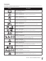 7
7
-
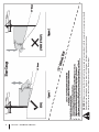 8
8
-
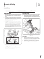 9
9
-
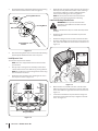 10
10
-
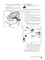 11
11
-
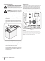 12
12
-
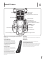 13
13
-
 14
14
-
 15
15
-
 16
16
-
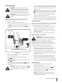 17
17
-
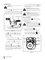 18
18
-
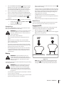 19
19
-
 20
20
-
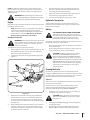 21
21
-
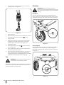 22
22
-
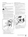 23
23
-
 24
24
-
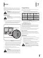 25
25
-
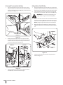 26
26
-
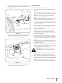 27
27
-
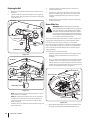 28
28
-
 29
29
-
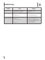 30
30
-
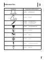 31
31
-
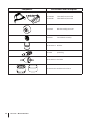 32
32
-
 33
33
-
 34
34
-
 35
35
-
 36
36
-
 37
37
-
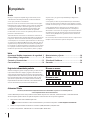 38
38
-
 39
39
-
 40
40
-
 41
41
-
 42
42
-
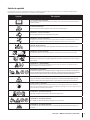 43
43
-
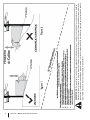 44
44
-
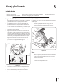 45
45
-
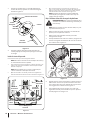 46
46
-
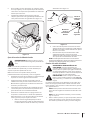 47
47
-
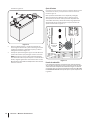 48
48
-
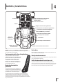 49
49
-
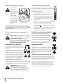 50
50
-
 51
51
-
 52
52
-
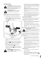 53
53
-
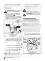 54
54
-
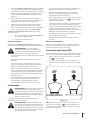 55
55
-
 56
56
-
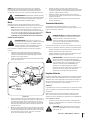 57
57
-
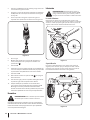 58
58
-
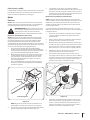 59
59
-
 60
60
-
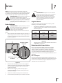 61
61
-
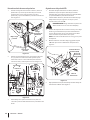 62
62
-
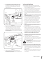 63
63
-
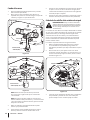 64
64
-
 65
65
-
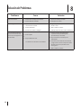 66
66
-
 67
67
-
 68
68
-
 69
69
-
 70
70
-
 71
71
-
 72
72


Troy-Bilt 17ARCBDW066 Manual de usuario
- Categoría
- Tractor
- Tipo
- Manual de usuario
- Este manual también es adecuado para
en otros idiomas
- English: Troy-Bilt 17ARCBDW066 User manual
Artículos relacionados
-
Troy-Bilt 13AN77KG011 Manual de usuario
-
Troy-Bilt 13AP61KP011 Manual de usuario
-
Troy-Bilt 17WF2ACP011 Manual de usuario
-
-
Troy-Bilt 17ARCBDW066 Manual de usuario
-
-
-
-
-
Troy-Bilt 13A721JD066 Manual de usuario