
1
Owner’s Manual
SmartOnline
®
Rack/Tower On-Line UPS Systems
Not suitable for mobile applications.
1. Important Safety Instructions 2
2. Installation 3
2.1 Mounting (Rack) 3
2.2 Mounting (Tower) 4
2.3 Connection and Start-Up 4
2.4 Optional Connections 5
3. Operation 8
3.1 Front Panel Switches 8
3.2 Advanced Operational 8
Settings
3.3 Front Panel Indicator Lights 9
3.4 Rear Panel 11
3.5 Communications 12
4. Troubleshooting 13
5. Battery Replacement 14
6. Storage and Service 16
6.1 Storage 16
6.2 Service 16
7. Product Registration and 17
Regulatory Compliance
Español 18
Français 35
Русский
52
1111 W. 35th Street, Chicago, IL 60609 USA • www.tripplite.com/support
Copyright © 2017 Tripp Lite. All rights reserved.
PROTECT YOUR INVESTMENT!
Register your product for quicker service
and ultimate peace of mind.
You could also win an
ISOBAR6ULTRA surge protector—
a $100 value!
www.tripplite.com/warranty
17-06-040-932882.indb 1 6/29/2017 10:33:09 AM

2
1. Important Safety Instructions
UPS Location Warnings
• Install the UPS system indoors, away from excess moisture or heat, conductive
contaminants, dust or direct sunlight.
• For best performance, keep the indoor temperature between 32º F and 104º F
(0º C and 40º C).
• Leave adequate space around all sides of the UPS system for proper ventilation.
• Do not mount the UPS system with its front or rear panel facing down (at any angle).
Mounting in this manner will seriously inhibit the UPS system’s internal cooling,
eventually causing product damage not covered under warranty.
UPS Connection Warnings
• Connect the UPS system directly to a properly grounded AC power outlet. The outlet
must be installed near the UPS system and must be easily accessible for disconnection.
• To reduce the risk of fire, connect only to a circuit provided with 20 amperes maximum
branch circuit overcurrent protection in accordance with your local and National
Electrical Code (NEC), ANSI/NFPA 70.
• Do not modify the UPS system’s plug, and do not use an adapter that would eliminate
the UPS system’s ground connection. Do not plug the UPS system into itself; this will
damage the UPS system.
• Do not use extension cords to connect the UPS system to an AC outlet.
• If the UPS system receives power from a motor-powered AC generator, the generator
must provide clean, filtered, computer-grade output.
Equipment Connection Warnings
• Use of this equipment in life support applications where failure of this equipment can
reasonably be expected to cause the failure of the life support equipment or to
significantly affect its safety or effectiveness is not recommended.
• Do not connect surge suppressors or extension cords to the output of the UPS system.
This might damage the UPS system and may affect the surge protector and UPS system
warranties. Connecting a Tripp Lite power distribution unit (PDU) to the output of the
UPS system is safe and will not void the warranty.
Battery Warnings
• Refer to Section 5: Battery Replacement for a complete list of battery warnings.
SAVE THESE INSTRUCTIONS
This manual contains instructions and warnings that should be followed during
the installation, operation and storage of this product. Failure to heed these
warnings may affect the warranty.
17-06-040-932882.indb 2 6/29/2017 10:33:15 AM

3
2. Installation
1
2
3
D
D
E
E
4
F
F
C
B
C
B
A
B
B
A
2.1 Mounting (Rack)
• Use the included rackmount shelves and mounting hardware to mount the UPS system
in a 4-post rack or rack enclosure. To mount the UPS system in a 2-post (telecom) rack,
order Tripp Lite’s 2-Post Rackmount Kit (model 2POSTRMKITWM, sold separately).
• The instructions in this manual are for common rack and rack enclosure types and may
not be appropriate for all mounting applications. The user must determine the fitness of
hardware and procedures before mounting. If hardware or procedures are not suitable
for the application, contact the manufacturer of the rack or rack enclosure for a
solution.
Warning: The UPS system is very heavy—be careful when moving or lifting it.
4-Post Mounting Procedure
1
The included plastic pegs
A
will support the
empty rackmount shelves
B
until the
permanent mounting hardware is installed.
Insert a peg near the center of the front and
rear bracket of each shelf as shown. (Each
front bracket has six holes and each rear
bracket has three holes.) The pegs will snap
into place.
After installing the pegs, expand each shelf to
match the depth of the vertical rack rails. The
pegs will fit through the square holes in the
rack rails to support the shelves. Confirm that
the shelves are level in all directions.
Note: The support ledge of each shelf must face
inward.
2
Secure the shelves
B
to the rack rails
permanently using the longer included screws
and washers
C
as shown. (Place four screws
at the front and four screws at the back.)
Tighten all screws before proceeding.
Warning: Do not attempt to install
the UPS system until the required
screws have been inserted and
tightened. The plastic pegs will not
support the weight of the UPS
system.
3
Attach the mounting brackets
D
to the
forward mounting holes of the UPS system
using the shorter included screws
E
. The
mounting bracket ears must face forward.
4
With the aid of an assistant, lift the UPS system and slide it onto the mounting
shelves. Insert four of the included screws
F
through the mounting bracket ears and
into the vertical rack rails. Tighten all screws securely.
17-06-040-932882.indb 3 6/29/2017 10:33:19 AM

4
1
2
Some models may differ.
1
Voltage Selection Mode
Please follow below procedure to select the
output voltage by front panel.
1. Press the ON/TEST and OFF buttons
simultaneously to enter “Voltage Selection”
mode. The three LEDs labeled VOLTAGE
SELECTION MODE will flash when you have
entered this mode.
2. Press the ON/TEST button to select the
output voltage from 200 to 240.
3. After selecting the desired output voltage,
press the ON/TEST and OFF buttons
simultaneously to save your selection and
exit “Voltage Selection” mode.
2. Installation
2.2 Mounting (Tower)
The UPS system can be mounted in an upright
tower position when used with Tripp Lite’s
optional base stand kit (model 2-9USTAND, sold
separately). When mounting the UPS system in a
tower position, make sure the control panel is
closer to the top of the cabinet than the bottom.
The control panel can be rotated to match the
orientation of the UPS system. Pull the panel
out, rotate it and push it back into place as
shown.
Warning: The UPS system is very
heavy—be careful when moving or
lifting it.
2.3 Connection and Start-Up
1
Plug the UPS system into an electrical
outlet.
Note: The UPS system does not include an input
power cord.
Connect a user-supplied power cord to the
IEC-320-C20 input receptacle. The power
cord should have an IEC-320-C19 connector
on one end and a plug appropriate for your
local site’s utility outlet on the other end.
The UPS system must be connected to a
dedicated circuit of sufficient amperage.
Refer to the UPS system nameplate for input
requirements.
After the UPS system is plugged in, the
following sequence of events will occur:
1. The fan will turn on and all LEDs will
illuminate momentarily.
2. The percent level LEDs (25%, 50%, 75%
and 100%) will illuminate one at a time.
3. The “LINE” and “LOAD” LEDs will
illuminate to indicate normal operation.
Note: Power will not be supplied to the outlets until
the UPS system is turned on.
17-06-040-932882.indb 4 6/29/2017 10:33:21 AM

5
Voltage Note: The UPS system supports a nominal AC voltage setting of 200V, 208V, 220V, 230V
or 240V. 230V is the factory default setting. The full output capacity of 2,500 watts is available
when the UPS system is set at 230V or 240V. When the UPS system is set at 200V, 208V or
220V, output capacity is reduced to 2,400 watts. The nominal voltage setting can be changed
using the control panel buttons, with PowerAlert
®
software or the optional WEBCARDLX internal
accessory card. See the PowerAlert software or WEBCARDLX documentation for more information
about changing the nominal voltage setting.
2
3
Some models may differ.
2. Installation
2
Plug equipment into the UPS system’s AC
outlets.
Note: Use the supplied C13 to C14 interconnection
cord.
The UPS system is designed to support
computer equipment only. The UPS system
will become overloaded if household
appliances or laser printers are connected to
its outlets.
Note: Additional interconnection cords (C13 to
C14) are available from Tripp Lite. Visit www.
tripplite.com. (Part # P004-006)
3
Turn the UPS system ON.
To turn on the UPS system, press the “ON/
TEST” button for approximately one second
until the UPS system beeps, then release the
button.
The UPS system will begin providing AC power
to its outlets. The “ON LINE” LED will
illuminate.
Note: UPS system will function properly upon initial
startup, however, maximum runtime for the unit’s
battery will only be accessible after it has been
charged for 24 hours.
17-06-040-932882.indb 5 6/29/2017 10:33:22 AM

6
4-5
2a
Some models may differ.
2b
1
USB and RS-232 Serial Communications
Use the included USB cable
1a
or RS-232
(DB9) serial cable
1b
to connect the UPS
system’s communication port to a
computer’s communication port. Install the
included PowerAlert software on the
computer. (See the PowerAlert software
documentation for system requirements and
installation instructions.)
2
EPO Port Connection
This optional feature is only for those
applications that require connection to a
facility’s Emergency Power Off (EPO) circuit.
When the UPS is connected to this circuit, it
enables emergency shutdown of the UPS’s
inverter and inhibits transfer to internal
bypass. Using the cable provided, connect
the EPO port of your UPS
2a
to a user-
supplied normally closed or normally open
switch according to the circuit diagram
2b
.
Notes:
1. If using a cable other than what is supplied, the
cable should not have a resistance of greater
than 5 ohms.
2. If a non-latching EPO switch is used, the EPO
must be held for a minimum of 1 second. This
does not apply to a latching EPO switch.
CAUTION: The EPO port is not a
phone line surge suppressor; do
not connect a phone line to this
port.
1b
Some models may differ.
1a
Some models may differ.
2. Installation
2.4 Optional Connections
The UPS system will function properly without these connections.*
* Note: PowerAlert software (included) or the optional WEBCARDLX internal accessory card is required
to control some of the advanced features of the UPS system, including economy mode and frequency
conversion settings. The factory defaults are suitable for most applications.
UPS Unit State when asserting EPO with AC line present:
LEDs Output Fans Serial SNMP USB
OFF OFF ON ON ON ON
To restart the UPS unit after asserting EPO with AC line present:
1. Verify that the EPO assertion has been removed or cleared.
2. Remove AC line power to the UPS unit.
3. Reapply AC line power. Now the UPS will start back up in Standby mode.
17-06-040-932882.indb 6 6/29/2017 10:33:24 AM

7
3
4
Some models may differ.
Some models may differ.
UPS Unit State when asserting EPO without AC line power:
LEDs Output Fans Serial SNMP USB
OFF OFF OFF OFF OFF OFF
To restart the UPS unit after asserting EPO without AC line power:
1. Verify that the EPO assertion has been removed or cleared.
2. Reapply AC line power to the UPS unit. Now the UPS will start back up in Standby mode.
3
External Battery Connection
4
Accessory Card Slot
The slot accommodates an optional internal
accessory card (model: WEBCARDLX, sold
separately). WEBCARDLX provides an
Ethernet network interface for remote
monitoring and control of the UPS system via
SNMP, Web or telnet. WEBCARDLX enables
remote reboots, shutdowns, load monitoring,
condition reporting and more. Use
WEBCARDLX with an optional environmental
sensor (model E2MT, E2MTDI, E2MTDO and
E2MTHDI, sold separately) to monitor
temperature and humidity or to control and
monitor alarms and security systems.
Remove the cover panel from the slot to
insert the accessory card. Refer to the
WEBCARDLX documentation for additional
installation instructions.
2. Installation
17-06-040-932882.indb 7 6/29/2017 10:33:26 AM

8
3. Operation
3.1 Front Panel Switches
“ON/TEST” Button: This button controls four separate functions:
UPS System Power ON
To turn on the UPS system, press the “ON/TEST” button for
approximately one second until the UPS system beeps, then release
the button. The “ON LINE” LED will illuminate.
UPS System Self-Test
To initiate a self-test of the battery during normal on-line operation,
press this button for approximately one second until the UPS system
beeps, then release it. The UPS system will shift to battery power for
10 seconds.
Note: All LEDs illuminate during a self-test.
Alarm Silence
To silence the UPS system’s on battery alarm, press this button and
hold it until the UPS system beeps, then release the button.
UPS System Cold Start
To use the UPS system as a stand-alone power source when AC
power is unavailable (i.e. during a blackout), press this button and
hold it until the UPS system beeps, then release the button. The
UPS system will then provide battery power to its outlets.*
* The “ON BATT” indicator light will be illuminated since the UPS system will
be operating from battery power.
“OFF” Button: This button turns off power to the UPS system’s
outlets. Press this button and hold it until the UPS system beeps,
then release it. The battery will continue to charge and the fan will
continue to operate even when the outlets are off. To turn the UPS
system off completely, including the battery charger, unplug the UPS
system’s power cord after pressing the “OFF” switch.
3.2 Advanced Operational Settings
Economy Mode
The UPS system supports economy mode operation to reduce energy consumption and
BTU emissions. In economy mode, the UPS system operates with increased efficiency
when the quality of utility power is satisfactory to pass through to connected equipment
without double conversion.
Economy mode saves energy by suspending double conversion when incoming voltage is
within -12%/+10% of the nominal voltage setting. If the nominal voltage setting is 230V,
the UPS system will remain in economy mode while utility line voltage is between
approximately 202V and 253V. If utility line voltage falls outside this range, the UPS
system will either switch back to standard on-line, double conversion mode or it will switch
to battery backup mode, depending on the severity of the voltage deviation.
Economy mode can be enabled (or disabled) through the included PowerAlert software or
the optional WEBCARDLX internal accessory card. The UPS system's yellow “BYPASS” LED
will illuminate continuously when economy mode is enabled. Refer to the PowerAlert or
WEBCARDLX documentation for more information.
17-06-040-932882.indb 8 6/29/2017 10:33:26 AM

9
On-line, double-conversion mode (default)
Typical line efficiency at full load: 89%
Output voltage range: ± 2% of nominal setting (200/208/220/230/240V)
Economy mode
Typical line efficiency at full load: 97%
Output voltage range: -12%/+10% of nominal setting (200/208/220/230/240V)
Frequency Conversion
The UPS system automatically selects 50 Hz or 60 Hz operation based on utility power
conditions at start-up and regulates output power within ± 0.05 Hz of the selected
frequency. The UPS system also has an advanced setting that allows continuous frequency
conversion from 50 Hz to 60 Hz or from 60 Hz to 50 Hz. The advanced frequency
conversion setting is accessible through the included PowerAlert software or the optional
WEBCARDLX internal accessory card. When continuous frequency conversion is enabled,
the maximum output capacity of the UPS system is derated by 25%.
3.3 Front Panel Indicator Lights
Note: All LEDs illuminate during a UPS system self-test.
3. Operation
“ON LINE” LED: This green LED will illuminate continuously to
indicate the UPS system is operating normally in on-line mode
(filtering and resynthesizing AC line input to provide pure sine wave
output). When this LED is illuminated, the load level of the UPS
system is displayed on the % level LEDs (25%, 50%, 75%, 100%).
“LINE” LED: This green LED will illuminate continuously to indicate
the utility-supplied AC line voltage at the wall outlet is nominal. It
will flash if the line voltage is outside the nominal range (either too
low or too high). User action is not required when the LED flashes;
the UPS system continuously and automatically filters AC line
power to provide equipment with pure sine wave AC power,
regardless of brownout or overvoltage conditions. If this LED is off,
then AC line voltage is not present (blackout) or is at an extremely
high voltage, and the UPS system will provide connected
equipment with power from its battery system.
“BYPASS” LED: This yellow LED will illuminate continuously when
the UPS system is in economy mode. The LED will flash when the
UPS system is bypass mode, indicating that the UPS system’s DC/
AC inverter is deactivated. The red “FAULT” LED will also illuminate
if the UPS system is in bypass mode. During normal operation the
bypass LED will illuminate briefly when the unit is plugged in. If an
internal fault or overload occurs, the LED will flash repeatedly to
show that connected equipment will receive filtered AC line power,
but will not receive battery power during a blackout. In this case,
contact Tripp Lite for service.
“FAULT” LED: This red LED will flash when the UPS system detects
an internal fault. If the condition persists after restarting the UPS
system, see Section 4: Troubleshooting.
17-06-040-932882.indb 9 6/29/2017 10:33:27 AM

10
3. Operation
“LOAD” LED: This green LED will illuminate when the UPS system
is receiving AC power. It also indicates that the % level LEDs (25%,
50%, 75%, 100%) are displaying the UPS load level.
“BATT” LED: This green LED will illuminate when the UPS system
is operating from battery power. It indicates that the % level LEDs
(25%, 50%, 75%, 100%) are displaying the battery charge level.
(The “ON BATT” LED will also be illuminated.)
% Level LEDs: These dual-function LEDs will indicate the % level
for either the load level (if the “LOAD” LED is lit) or the battery
charge level (if the “BATT” LED is lit).
“OVERLOAD” LED: This red LED will illuminate continuously to
indicate that the UPS system’s capacity has been exceeded. The
UPS alarm will beep continuously. Immediately unplug some
equipment until the LED and alarm go off. If the overload is not
corrected immediately, the UPS system will go from on-line to
bypass mode.
“BATT LOW” LED: This yellow LED will illuminate when the UPS
system’s battery charge level is low. The UPS alarm will beep until
the batteries are either depleted or adequately recharged.
“ON BATT” LED: This green LED will illuminate continuously to
indicate that AC line voltage is absent (or out of range) and the
UPS system is providing equipment with battery-derived AC power.
The UPS system will also beep every two seconds (unless silenced
by the “ON/TEST” button) and the % level LEDs (25%, 50%, 75%,
100%) will display the battery charge level.
“REPLACE BATT” LED: This red LED will illuminate continuously
and the UPS alarm will beep every two seconds if the UPS system
fails the automatic self-test. Allow the UPS system to charge for at
least 12 hours and perform a self-test as described in Section
3.1: Front Panel Switches. If the condition persists, contact
Tripp Lite.
17-06-040-932882.indb 10 6/29/2017 10:33:29 AM

11
IEC-320-C20
CONTROLLABLE LOAD 1
CONTROLLABLE LOAD 2 UNSWITCHED
IEC-320-C13
IEC-320-C19
3. Operation
3.4 Rear Panel
Accessory Card Slot: Remove the cover panel from this slot to
install an optional internal WEBCARDLX accessory, sold separately.
WEBCARDLX provides a network interface for monitoring and
control via SNMP, Web or telnet, enabling remote reboots,
shutdowns and more.
External Battery Pack Connector
(Configuration Varies By Model)
Fan: The fan cools the UPS system’s internal components. It is
always on when line power is present, even if power to the UPS
system’s outlets is turned off.
Input Power Cord: This UPS system requires a user-supplied
power cord. This power cord should have an IEC-320-C19
connector on one end and a plug appropriate for your local site's
utility outlet on the other end.
AC Outlets (Configuration Varies By Model): These outlets
provide connected equipment with pure sine wave AC output
derived from the AC line during normal operation and derived from
battery power during blackouts and severe brownouts or
overvoltages. Output power is filtered to protect connected
equipment against damaging surges and line noise.
The outlets are divided into numbered load banks, as labelled on
the unit. Using included PowerAlert software and cabling or an
optional WEBCARDLX, load banks may be individually turned off
and on from a remote location, allowing users to reset or reboot
connected equipment.
17-06-040-932882.indb 11 6/29/2017 10:33:32 AM

12
RS-232 (DB9)
3.5 Communications
Communication Ports (USB and/or RS-232): These ports connect
the UPS system to a computer. Use with Tripp Lite’s PowerAlert
software and included cabling to allow the computer to
automatically save open files and shut down during a blackout. Also
use PowerAlert software to control UPS system load banks and
monitor a wide variety of AC line power and UPS system operating
conditions. See Section 2.4: Optional Connections for cable
connection instructions. Refer to the PowerAlert documentation for
software installation instructions.
The RS-232 port can also be used as a contact closure port. The
port’s numbered pin assignments are shown in the RS-232 (DB9)
illustration at left. If the battery charge level is low, the UPS system
will bridge pins 1 and 5. If utility power fails, the UPS system will
bridge pins 8 and 5. To shut down the UPS system remotely, short
pin 3~pin 9 for at least 3.8 seconds.
EPO (Emergency Power Off) Port: The UPS system has an EPO
port that may be used to connect the UPS system to a contact
closure switch to enable emergency UPS system shutdown. See
Section 2.4: Optional Connections for more information. If the
unit has been shut down due to an EPO event, it will be necessary
to disconnect the unit from utility power to reset the unit. After
re-connecting to utility power, see Section 2.3 Installation for
start-up instructions.
USB
3. Operation
17-06-040-932882.indb 12 6/29/2017 10:33:33 AM

13
The UPS system control panel LEDs will illuminate in the sequences listed below to
indicate operational problems.
Note: If the “FAULT” LED illuminates, determine the specific fault condition by activating the error
code LEDs. To activate the error code LEDs, press the “ON/TEST” button until the UPS system beeps,
then release the button. The error code LEDs will illuminate for five seconds.
Illuminated LEDs Condition and Solution
On: REPLACE BATT
Error Code LEDs: Not Applicable
Replace Battery: Allow the UPS system to charge for
at least 12 hours and perform a UPS system self-test as
described in Section 3.1: Front Panel Switches. If the
LED remains on, contact Tripp Lite for service.
Flashing: LINE
Error Code LEDs: Not Applicable
Input Abnormal: Utility power voltage or frequency is too
high or too low for the UPS system to operate in BYPASS
mode. If an inverter failure occurs, the UPS system will
not pass through utility power to the outlets and any
connected equipment will turn off.
On: FAULT
Error Code LEDs: 50% 100%
Battery Weak: Allow the UPS system to charge for 12
hours. If the LED remains on, contact Tripp Lite for service.
On: FAULT
Error Code LEDs: 25% 75%
Inverter Over-Current: Reduce the load supported by the
UPS system by unplugging some equipment. Restart the
UPS system. If the problem persists, contact Tripp Lite for
service.
On: FAULT
Error Code LEDs: 25% 75% 100%
Internal Temperature Too High: Confirm that adequate
space exists for air to circulate near the UPS system’s
vents. Confirm that the UPS system’s fan is working
properly. Confirm that the ambient temperature does not
exceed recommended levels. Restart the UPS system.
On: FAULT
Error Code LEDs: 25% 50%
Inverter Overload: Reduce the load supported by the
UPS system by unplugging some equipment.
On: FAULT
Error Code LEDs: 25% 50% 100%
Charger Out of Order: Restart the UPS system. If the
problem persists, contact Tripp Lite for service.
On: FAULT
Error Code LEDs: 25% 50% 75%
Fan Out of Order: Restart the UPS system. If the problem
persists, contact Tripp Lite for service.
On: FAULT
Error Code LEDs: 25% 50% 75% 100%
Bypass Phase Can’t Lock: Restart the UPS system. If
the problem persists, contact Tripp Lite for service.
On: FAULT
Error Code LEDs: BATT 25%
Utility Voltage Low and Battery Disconnected at
Initialization: Shut down the UPS system. Check the
internal battery connections. Correct the AC input voltage.
Restart the UPS system. If the problem persists, contact
Tripp Lite for service.
On: FAULT
Error Code LEDs: BATT 25% 100%
Battery Disconnected at Initialization and Utility
Voltage or Frequency Too High or Too Low in On-Line
Mode: Shut down the UPS system. Check the internal
battery connections. Correct the AC input voltage. Restart
the UPS system. If the problem persists, contact Tripp Lite
for service.
On: FAULT
Error Code LEDs: BATT 25% 75%
Input Over-Current: Reduce the load supported by the UPS
system by unplugging some equipment. Restart the UPS
system. If the problem persists, contact Tripp Lite for service.
On: FAULT
Error Code LEDs: BATT 25% 50%
Bypass Overload: Reduce the load supported by the UPS
system by unplugging some equipment. Either wait for the
UPS system to recognize the load reduction or restart the UPS
system. If the problem persists, contact Tripp Lite for service.
On: FAULT
Error Code LEDs: BATT 25% 50% 100%
Battery Voltage Too High: Restart the UPS system. If the
problem persists, contact Tripp Lite for service.
Note: All other error codes indicate internal fault conditions. Restart the UPS system. If the problem
persists, contact Tripp Lite for service.
4. Troubleshooting
17-06-040-932882.indb 13 6/29/2017 10:33:33 AM

14
Under normal conditions, the original batteries in the UPS system will last several years.
The batteries are designed for hot-swap replacement (i.e. replacement while the UPS
system is in ON mode), but some qualified service personnel may wish to put the UPS
system in OFF mode and disconnect equipment before proceeding.
Battery Warnings
Caution: There are no user-serviceable parts inside the UPS system. Battery service or
replacement must be performed or supervised by qualified service personnel familiar
with batteries and the required precautions.
Caution: When replacing batteries, replace only with the same type and number of
batteries.
• Batteries can present a risk of electrical shock and burn from high short-circuit current.
Observe proper precautions. Do not dispose of the batteries in a fire. Do not open the
UPS or batteries. Do not short or bridge the battery terminals with any object.
Unplug and turn off the UPS before performing battery replacement. Use tools with
insulated handles. There are no user-serviceable parts inside the UPS. Battery
replacement should be performed only by authorized service personnel using the same
number and type of batteries (Sealed Lead-Acid). The batteries are recyclable.
Refer to your local codes for disposal requirements or visit http://www.tripplite.com/
support/recycling-program for recycling information. Tripp Lite offers a complete line of
UPS System Replacement Battery Cartridges (R.B.C.).Visit Tripp Lite on the Web at
http://www.tripplite.com/products/battery-finder/ to locate the specific replacement
battery for your UPS.
5. Battery Replacement
17-06-040-932882.indb 14 6/29/2017 10:33:33 AM

15
1
2
3
6
5
4
Procedure
1
Remove Front Panel
2
Remove Battery Compartment Cover
3
Disconnect Old
Batteries and Remove Old Batteries
4
Insert New Batteries and Connect New Batteries
(Attach battery connectors black-to-black and red-to-red.)
5
Replace Battery
Compartment Cover
6
Replace Front Panel
7
Recycle Old Batteries
7
5. Battery Replacement
17-06-040-932882.indb 15 6/29/2017 10:33:40 AM

16
6. Storage and Service
6.1 Storage
First turn the UPS system OFF: press the “OFF” switch to turn power off at the UPS
system’s outlets, then disconnect the UPS system’s power cord from the wall outlet. Next,
disconnect all equipment to avoid battery drain. If the UPS system will be stored for an
extended period of time, recharge the UPS system’s batteries fully every three months by
plugging the UPS system into a live AC outlet and allowing the UPS system to charge for
4-6 hours. If the UPS system’s batteries are left discharged for an extended period of time,
they may suffer a permanent loss of capacity.
6.2 Service
A variety of Extended Warranty and On-Site Service Programs are also available from
Tripp Lite. For more information on service, visit www.tripplite.com/support. Before returning
your product for service, follow these steps:
1. Review the installation and operation procedures in this manual to insure that the
service problem does not originate from a misreading of the instructions.
2. If the problem continues, do not contact or return the product to the dealer. Instead,
visit www.tripplite.com/support.
3. If the problem requires service, visit www.tripplite.com/support and click the Product
Returns link. From here you can request a Returned Material Authorization (RMA)
number, which is required for service. This simple on-line form will ask for your unit’s
model and serial numbers, along with other general purchaser information. The RMA
number, along with shipping instructions will be emailed to you. Any damages (direct,
indirect, special or consequential) to the product incurred during shipment to Tripp Lite
or an authorized Tripp Lite service center is not covered under warranty. Products
shipped to Tripp Lite or an authorized Tripp Lite service center must have transportation
charges prepaid. Mark the RMA number on the outside of the package. If the product
is within its warranty period, enclose a copy of your sales receipt. Return the product
for service using an insured carrier to the address given to you when you request the
RMA.
17-06-040-932882.indb 16 6/29/2017 10:33:40 AM

17
PRODUCT REGISTRATION
Visit www.tripplite.com/warranty today to register your new Tripp Lite product. You’ll be automatically entered
into a drawing for a chance to win a FREE Tripp Lite product!*
* No purchase necessary. Void where prohibited. Some restrictions apply. See website for details.
Regulatory Compliance Identification Numbers: For the purpose of regulatory compliance certifications
and identification, this Tripp Lite product has been assigned a unique series number. The series number can
be found on the product nameplate label, along with all required approval markings and information. When
requesting compliance information for this product, always refer to the series number. The series number
should not be confused with the marking name or model number of the product.
FCC Notice, Class A
This device complies with part 15 of the FCC Rules. Operation is subject to the following two conditions: (1)
This device may not cause harmful interference, and (2) this device must accept any interference received,
including interference that may cause undesired operation.
Note: This equipment has been tested and found to comply with the limits for a Class A digital device,
pursuant to part 15 of the FCC Rules. These limits are designed to provide reasonable protection against
harmful interference when the equipment is operated in a commercial environment. This equipment
generates, uses, and can radiate radio frequency energy and, if not installed and used in accordance with the
instruction manual, may cause harmful interference to radio communications. Operation of this equipment in
a residential area is likely to cause harmful interference in which case the user will be required to correct the
interference at his own expense. The user must use shielded cables and connectors with this equipment. Any
changes or modifications to this equipment not expressly approved by Tripp Lite could void the user’s authority
to operate this equipment.
WEEE Compliance Information for Tripp Lite Customers and Recyclers (European Union)
Under the Waste Electrical and Electronic Equipment (WEEE) Directive and implementing regulations,
when customers buy new electrical and electronic equipment from Tripp Lite they are entitled to:
• Send old equipment for recycling on a one-for-one, like-for-like basis
(this varies depending on the country)
• Send the new equipment back for recycling when this ultimately becomes waste
Tripp Lite has a policy of continuous improvement. Specifications are subject to change without notice.
7. Product Registration and Regulatory Compliance
1111 W. 35th Street, Chicago, IL 60609 USA • www.tripplite.com/support
17-06-040-932882.indb 17 6/29/2017 10:33:40 AM

18
Manual del Propietario
Sistemas UPS
SmartOnline
®
en Rack/Torre 100% en Línea
No conveniente para los usos móviles.
1. Instrucciones de 19
Seguridad Importantes
2. Instalación 20
2.1 Instalación (Rack) 20
2.2 Instalación (Torre) 21
2.3 Conexión y Arranque 21
2.4 Conexiones Opcionales 22
3. Operación 25
3.1 Interruptores del 25
Panel Frontal
3.2 Ajustes Operacionales 25
Avanzados
3.3 Luces Indicadoras del 26
Panel Frontal
3.4 Panel Posterior 28
3.5 Comunicaciones 29
4. Solución de Problemas 30
5. Reemplazo de Baterías 31
6. Almacenamiento y 33
Reparaciones
6.1 Almacenamiento 33
6.2 Reparaciones 33
7. Cumplimiento de las Normas 34
English 1
Français 35
Русский
52
1111 W. 35th Street, Chicago, IL 60609 USA • www.tripplite.com/support
Copyright © 2017 Tripp Lite. Todos los derechos reservados.
17-06-040-932882.indb 18 6/29/2017 10:34:35 AM

19
1.
Instrucciones de Seguridad Importantes
Advertencias sobre la Ubicación del UPS
• Instale el sistema UPS en interior, alejado de humedad o calor excesivos, contaminantes
conductores, polvo o luz solar directa.
• Para lograr el mejor rendimiento, mantenga la temperatura interior entre 0º C y 40º C (32º F
y 104º F).
• Deje un espacio adecuado alrededor de todos los costados del sistema UPS para que haya
una ventilación adecuada.
• No monte esta unidad con el panel frontal o con el panel trasero hacia abajo (Bajo ningún
ángulo o inclinación). Si lo monta de esta manera, inhibirá seriamente el sistema de
enfriamiento interno de la unidad; lo que finalmente causará daños al producto que no están
cubiertos por la garantía.
Advertencias para la Conexión del UPS
• Conecte el sistema UPS directamente a un tomacorriente de CA conectado a tierra
adecuadamente. El tomacorriente debe instalarse cerca del sistema UPS y tiene que tener un
fácil acceso para poder desconectarlo.
• A fin de reducir el riesgo de incendio, conecte solo a un circuito proporcionado con una
protección contra sobrecorriente con circuito de bifurcación de un máximo de 20 amperes de
acuerdo con su local y NEC (Código Eléctrico Nacional), ANSI/NFPA 70.
• No modifique la clavija del sistema UPS y tampoco use un adaptador que elimine la conexión
a tierra de la unidad. No enchufe el UPS en sí mismo, ya que esto lo dañará.
• No use cables de extensión para enchufar el sistema UPS a una salida CA.
• Si el sistema UPS recibe energía de un generador de CA alimentado por motor, el generador
debe proporcionar una salida de grado de computadora limpia y filtrada.
Advertencias acerca de la Conexión del Equipo
• El uso de este equipo en aplicaciones de soporte de vida en donde la falla de este equipo
pueda razonablemente hacer suponer que causará fallas en el equipo de soporte de vida o
afecte significativamente su seguridad o efectividad, no está recomendado.
• No conecte los supresores de sobretensiones o cables de extensión a la salida del sistema
UPS. Esto puede dañar el UPS y afectar las garantías del supresor de sobretensiones y del
UPS. La conexión de una unidad de distribución de energía (PDU) Tripp Lite a la salida del
sistema UPS es segura y no anulará la garantía.
Advertencias sobre la Batería
• Consulte la Sección 5: Reemplazo de Baterías para obtener una lista completa de
advertencias sobre la batería.
GUARDE ESTAS INSTRUCCIONES
Este manual contiene instrucciones y advertencias que deben seguirse durante la
instalación, operación y almacenamiento de este producto. La falta de observar
estas advertencias podría afectar su garantía.
17-06-040-932882.indb 19 6/29/2017 10:34:35 AM

20
2. Instalación
1
2
3
D
D
E
E
4
F
F
C
B
C
B
A
B
B
A
2.1 Instalación (Rack)
• Use los estantes para rackmount y lo accesorios de instalación incluidos para instalar el
sistema UPS en un rack o estante de 4 postes. Para instalar el sistema UPS en un rack de 2
postes (telecomunicaciones), pida el juego para rackmount en 2 postes de
Tripp Lite (modelo 2POSTRMKITWM, se vende por separado).
• Las instrucciones de este manual son para tipos de racks y estantes comunes y puede que
no sean adecuadas para todas las aplicaciones de montaje. El usuario debe determinar la
idoneidad de los accesorios y los procedimientos antes de la instalación. Si los accesorios o
procedimientos no son apropiados para la aplicación, póngase en contacto con el fabricante
del rack o gabinete para obtener una solución.
Advertencia: El sistema UPS es muy pesado, así que tenga cuidado cuando lo
mueve o lo levanta.
Procedimiento de Instalación en 4 Postes
1
Los ganchos plásticos
A
incluidos soportarán los
estantes
B
para rackmount vacíos hasta que se
instalen los accesorios de instalación
permanentes. Inserte un gancho cerca del centro
del soporte frontal y posterior de cada estante
como se muestra. (Cada soporte frontal tiene
seis orificios y cada soporte posterior posee tres
orificios.) Los ganchos encajarán en su lugar.
Después de colocar los ganchos, expanda cada
estante para que se ajuste con la profundidad de
los rieles del rack vertical. Los ganchos encajarán
en los orificios cuadrados en los rieles del rack
para sostener los estantes. Confirme que los
estantes estén nivelados en todas las direcciones.
Nota: El reborde de soporte de cada estante debe
quedar mirando hacia adentro.
2
Asegure de manera permanente los estantes
B
a los rieles del rack usando los tornillos más
largos que vienen incluidos y las arandelas
C
como se muestra. (Coloque quatro tornillos en
la parte frontal y quatro tornillos en la parte
posterior.) Apriete todos los tornillos antes de
continuar.
Advertencia: No intente instalar el
sistema UPS hasta que se hayan
insertado y apretado los tornillos
necesarios. Los ganchos plásticos no
soportarán el peso del UPS.
3
Una los soportes de montaje
D
a los orificios
de montaje hacia delante del sistema UPS
usando los tornillos más cortos
E
que vienen
incluidos. Las orejas del soporte de montaje
deben mirar hacia adelante.
4
Con la ayuda de un asistente, levante el sistema UPS y deslícelo dentro de los estantes de
montaje. Inserte quatro de los tornillos
F
incluidos a través de las orejas del soporte de
montaje y en los rieles del rack vertical. Apriete todos los tornillos de manera segura.
17-06-040-932882.indb 20 6/29/2017 10:34:36 AM

21
1
2
Algunos modelos pueden ser diferentes.
1
Modo de Selección de Tensión
Use el procedimiento descrito enseguida para
seleccionar la tensión de salida en el tablero frontal.
1. Pulse los botones ON/TEST (ENCENDIDO/
PRUEBA) y OFF (APAGADO) simultáneamente
para ingresar al modo Selección de tensión. Los
tres LED rotulados VOLTAGE SELECTION MODE
(Modo de selección de tensión) destellarán al
ingresar a este modo.
2.
Pulse el botón ON/TEST (ENCENDIDO/PRUEBA) para
seleccionar la tensión de salida de 200 a 240.
3. Después de seleccionar la tensión de salida
deseada, pulse los botones ON/TEST
(ENCENDIDO/PRUEBA) y OFF (APAGADO)
simultáneamente para guardar su selección y
salir del modo “Selección de tensión”.
2. Instalación
2.2 Instalación (Torre)
El sistema UPS puede instalarse en una posición de
torre vertical usando el juego de pedestal opcional
de Tripp Lite (modelo 2-9USTAND, se vende por
separado). Cuando se monta el sistema UPS en
posición de torre, asegúrese de que el panel de
control esté más cerca de la parte superior del
gabinete que de la inferior.
El panel de control puede girarse para que
concuerde con la orientación del sistema UPS. Tire
y saque el panel, gírelo y vuelva a empujarlo en su
lugar como se muestra.
Advertencia: El sistema UPS es muy
pesado, así que tenga cuidado cuando
lo mueve o lo levanta.
2.3 Conexión y Arranque
1
Conecte el sistema UPS a un tomacorriente
eléctrico.
Nota: El sistema de UPS no incluye un cable de
alimentación eléctrica de entrada.
Conecte un cable de alimentación suministrado
por el usuario al receptáculo de entrada IEC-
320-C20. El cable de alimentación debe tener
un conector IEC-320-C19 en un extremo y un
enchufe apropiado para el tomacorriente de la
red eléctrica local en el otro extremo.
El sistema UPS debe conectarse a un circuito
dedicado con suficiente amperaje. Consulte la
placa de datos del sistema UPS para ver los
requisitos de entrada.
Después de enchufar el UPS, se producirá la
siguiente secuencia de eventos:
1. El ventilador se encenderá y todos los LEDs
se iluminarán de forma momentánea.
2. Se iluminarán los LEDs de nivel de
porcentaje (25%, 50%, 75% y 100%)
de a uno a la vez.
3. Se iluminarán los LEDs “LINE” (LÍNEA) y
“LOAD” (CARGA) que indican que hay un
funcionamiento normal.
Nota: No se suministrará alimentación a las
salidas hasta que el sistema esté encendido.
17-06-040-932882.indb 21 6/29/2017 10:34:37 AM

22
Nota sobre voltaje: El sistema UPS admite un voltaje de CA nominal de 200V, 208V, 220V,
230V o 240V. El ajuste predeterminado de fábrica es de 230V. La capacidad de salida completa
de 2,500 watts se encuentra disponible cuando el sistema UPS se ajusta en 230V o 240V.
Cuando el UPS se ajusta en 200V, 208V o 220V, la capacidad de salida se reduce a 2,400
watts. El ajuste de voltaje nominal puede cambiarse usando los botones del tablero de control
con el software PowerAlert
®
o la tarjeta auxiliar interna WEBCARDLX opcional. Consulte la
documentación sobre el software PowerAlert o la WEBCARDLX para obtener mayor información
sobre el cambio del ajuste del voltaje nominal.
2
3
Algunos modelos
pueden ser diferentes.
2. Instalación
2
Enchufe el equipo en las salidas CA del
sistema UPS.
Nota: Use el cable de interconexión C13 a C14,
suministrado.
El sistema UPS está diseñado únicamente para
mantener equipos computacionales. El UPS se
sobrecargará si en sus salidas se conectan
electrodomésticos o impresoras láser.
Nota: Puede obtener cables de interconexión
adicionales (C13 a C14) en Tripp Lite. Visite
www.tripplite.com. (Número de parte P004-006)
3
ENCIENDA el sistema UPS.
Para encender el UPS, presione el botón “ON/
TEST” (ENCENDIDO/PRUEBA) durante
aproximadamente un segundo hasta que oiga
un bip, luego suelte el botón.
El sistema UPS comenzará a entregar
alimentación de CA a sus salidas. Se iluminará
el LED “ON LINE” (EN LÍNEA).
Nota: el sistema UPS funcionará adecuadamente
desde la puesta en marcha inicial, no obstante, la
autonomía máxima de la batería de la unidad solo
se alcanzará después de que se haya cargado
durante 24 horas.
17-06-040-932882.indb 22 6/29/2017 10:34:38 AM

23
4-5
2a
Algunos modelos
pueden ser diferentes.
2b
1
Comunicaciones USB y Serial RS-232
Utilice el cable USB
1a
o el cable serial
RS-232 (DB9)
1b
que vienen incluidos para
conectar el puerto de comunicación del sistema
UPS al puerto de comunicación de una
computadora. Instale el software PowerAlert
incluido en la computadora. (Vea la
documentación del software PowerAlert para
conocer los requisitos del sistema y las
instrucciones de instalación.)
2
Conexión del Puerto EPO
Esta característica opcional es únicamente para
aquellas aplicaciones que requieran conexión a
un circuito de Apagado de Emergencia (EPO) de
la instalación. Cuando se conecta el UPS a este
circuito, permite el apagado de emergencia del
inversor del UPS e inhibe la transferencia a un
rodeo interno. Usando el cable proporcionado,
conecte el puerto EPO de su UPS
2a
a un
interruptor, proporcionado por el usuario,
normalmente abierto o normalmente cerrado de
acuerdo con el diagrama de circuito
2b
.
Notas:
1. Si se usa un cable diferente al suministrado,
éste no debe tener una resistencia superior a 5
ohms.
2. Si se usa un interruptor de EPO sin seguro, el
interruptor EPO deberá sujetarse por un mínimo
de 1 segundo. Ésto no aplica a un
interruptor EPO con seguro.
PRECAUCIÓN: El puerto EPO no es
un supresor de sobretensiones de
línea telefónica; no conecte una
línea telefónica a este puerto.
1b
Algunos modelos
pueden ser diferentes.
1a
Algunos modelos
pueden ser diferentes.
2. Instalación
2.4 Conexiones Opcionales
El sistema UPS funcionará adecuadamente sin estas conexiones.*
* Nota: Se requiere el software PowerAlert (incluido) o la tarjeta auxiliar interna WEBCARDLX opcional
para controlar algunos de los recursos avanzados del sistema UPS, como el modo económico y los
ajustes de conversión de frecuencia. Los valores predeterminados de fábrica son adecuados para la
mayoría de las aplicaciones.
Estado del UPS cuando activa EPO con línea CA presente:
LEDs Salidas Ventiladores Serial SNMP USB
Apagados Apagadas Encendidos Encendido Encendido Encendido
Para reiniciar el UPS después que se activa EPO con línea CA presente:
1. Verifique que la activación de EPO se ha eliminado o borrado.
2. Elimine la alimentación de línea CA al UPS.
3. Reconecte la energía de línea CA. Ahora el UPS iniciará el respaldo en modo de Standby.
17-06-040-932882.indb 23 6/29/2017 10:34:39 AM

24
3
4
Algunos modelos pueden ser diferentes.
Algunos modelos pueden ser diferentes.
Estado del UPS cuando activa EPO sin línea CA presente:
LEDs Salidas Ventiladores Serial SNMP USB
Apagado Apagadas Apagados Apagado Apagado Apagado
Para reiniciar el UPS después que se activa EPO sin energía de línea CA:
1. Verifique que la activación de EPO se ha eliminado o borrado.
2. Reconecte la alimentación de línea CA al UPS. Ahora el UPS iniciará el respaldo en modo de
Standby.
3
Conexión de Baterías Externas
4
Ranura para Tarjeta Auxiliar
La ranura acomoda una tarjeta auxiliar interna
opcional (modelo WEBCARDLX, se vende por
separado). La WEBCARDLX proporciona una
interfaz de red Ethernet para monitoreo y control
remotos del sistema UPS mediante SNMP, web
o telnet. La WEBCARDLX permite una
reinicialización, apagados, monitoreo de carga,
informe de condiciones y más de manera
remota. Utilice WEBCARDLX con sensor
ambiental opcional (modelos E2MT, E2MTDI,
E2MTDO y E2MTHDI, se vende por separado)
para monitorear la temperatura y la humedad o
para controlar y monitorear alarmas y sistemas
de seguridad.
Quite el panel de la cubierta de la ranura para
insertar la tarjeta auxiliar. Consulte la
documentación de la WEBCARDLX para obtener
instrucciones de instalación adicionales.
2. Instalación
17-06-040-932882.indb 24 6/29/2017 10:34:39 AM

25
3. Operación
3.1 Interruptores del Panel Frontal
Botón “ON/TEST”: Este botón controla quatro funciones distintas.
ENCENDIDO del UPS
Para encender el UPS, presione el botón “ON/TEST” (ENCENDIDO/
PRUEBA) durante aproximadamente un segundo hasta que oiga un bip,
luego suelte el botón. Se iluminará el LED “ON LINE” (EN LÍNEA).
Prueba Automática del UPS
Para iniciar una prueba automática de la batería durante el
funcionamiento en línea normal, presione este botón durante
aproximadamente un segundo hasta que se oiga un bip, luego suéltelo.
El UPS cambiará a energía de la batería durante 10 segundos.
Nota: Todos los LEDs se iluminarán durante una prueba automática.
Silencio de la Alarma
Para silenciar la alarma de la batería encendida del sistema UPS,
mantenga presionado este botón hasta que se oiga un bip, luego
suéltelo.
Arranque en Frío del Sistema UPS
Para usar el sistema UPS como una fuente de energía autónoma
cuando no hay disponible alimentación de CA (es decir, durante un
apagón), mantenga presionado este botón hasta que se oiga un bip,
luego suéltelo. Entonces, el UPS entregará energía de la batería a sus
salidas.*
*La luz indicadora “ON BATT” (BAT. ENCEND.) se iluminará desde el
momento en el que el sistema UPS opere con energía de la batería.
Botón “OFF” (APAGADO): Este botón apaga la alimentación a las
salidas del sistema UPS. Manténgalo presionado hasta que se oiga un
bip, luego suéltelo. La batería seguirá cargándose y el ventilador seguirá
funcionando aun cuando las salidas estén apagadas. Para apagar
completamente el UPS, incluyendo el cargador de la batería, desenchufe
el cable de alimentación del sistema UPS después de presionar el
interruptor de “OFF” (APAGADO).
3.2 Ajustes Operacionales Avanzados
Modo Económico
El sistema UPS admite una operación de modo económico para reducir el consumo de energía y
las emisiones de BTU. En el modo económico, el sistema UPS funciona con mayor eficiencia
cuando la calidad de la energía de la red pública es satisfactoria para que pase a través del
equipo conectado sin conversión doble.
El modo económico ahorra energía suspendiendo la doble conversión cuando el voltaje de
entrada está entre -12%/+10% del ajuste de voltaje nominal. Si el ajuste de voltaje nominal es
de 230V, el sistema UPS seguirá en modo económico mientras el voltaje de línea de la red
pública esté entre aproximadamente 202V y 253V. Si el voltaje de la línea de la red pública cae
fuera de este alcance, el sistema UPS cambiará a modo en línea de doble conversión estándar
o pasará a modo de respaldo, dependiendo de la gravedad de la desviación de voltaje.
El modo económico puede activarse (o desactivarse) a través del software PowerAlert incluido o
la tarjeta auxiliar interna WEBCARDLX opcional. Cuando esté activado el modo económico, se
iluminará de manera continua el LED “BYPASS” (RODEO) amarillo del sistema UPS. Para mayor
información, consulte la documentación de PowerAlert o la WEBCARDLX.
17-06-040-932882.indb 25 6/29/2017 10:34:39 AM

26
Modo de doble conversión 100% en línea (predeterminado)
Eficiencia de línea típica a carga completa: 89%
Rango del voltaje de salida: ±2% de ajuste nominal (200/208/220/230/240V)
Modo económico
Eficiencia de línea típica a carga completa: 97%
Rango del voltaje de salida: -12% /+10% de ajuste nominal (200/208/220/230/240V)
Conversión de Frecuencia
El sistema UPS selecciona automáticamente una operación en 50 Hz o 60 Hz basada en las
condiciones de la energía de la red pública en el arranque y regula la energía de salida dentro
de ±0.05 Hz de la frecuencia seleccionada. El sistema UPS también tiene un ajuste avanzado
que permite una conversión de frecuencia continua de 50 Hz a 60 Hz o desde 60 Hz hasta 50
Hz. Se puede acceder al ajuste de conversión de frecuencia avanzada a través del software
PowerAlert incluido o la tarjeta auxiliar interna WEBCARDLX opcional. Cuando se activa la
conversión de frecuencia continua, la capacidad máxima de salida del UPS se corrige en 25%.
3.3 Luces Indicadoras del Panel Frontal
Nota: Todos los LEDs se iluminarán durante una prueba automática del sistema UPS.
3. Operación
LED “ON LINE” (EN LÍNEA): Este LED verde se iluminará de manera
continua para indicar que el sistema UPS está funcionando con
normalidad en el modo en línea (filtrando y resintetizando la entrada
de la línea CA para proporcionar una salida de onda sinusoidal pura).
Cuando este LED se ilumina, el nivel de carga del sistema UPS
aparece en los LEDs de nivel de % (25%, 50%, 75%, 100%).
LED “LINE” (LÍNEA): Este LED verde se iluminará de manera continua
para indicar que el voltaje de la línea CA suministrado por la red
pública en el tomacorriente de pared es nominal. Parpadeará en caso
de que el voltaje de la línea esté fuera del rango nominal (ya sea
demasiado bajo o demasiado alto). No se requiere acción del usuario
cuando el LED parpadea; el sistema UPS filtra de manera continua y
automática alimentación de la línea CA para brindar al equipo
alimentación de CA con onda sinusoidal pura, sin importar las
condiciones de caída de voltaje o sobrevoltaje. Si este LED está
apagado, entonces no hay presente voltaje de la línea CA (apagón) o
está a un voltaje extremadamente alto, y el sistema UPS entregará al
equipo conectado energía de su sistema de baterías.
LED “BYPASS” (RODEO): Este LED “BYPASS” amarillo se iluminará
continuamente cuando el sistema UPS esté en modo económico. Este
LED parpadeará cuando el sistema UPS esté en modo de rodeo, lo que
indica que el inversor de CD/CA del sistema UPS está desactivado. El
LED “FAULT” (FALLA) también se iluminará cuando el UPS esté en modo
de rodeo. Durante un funcionamiento normal, este LED de rodeo
iluminará brevemente cuando la unidad está enchufada. Si se produce
una falla interna o sobrecarga, el LED parpadeará repetidamente para
mostrar que el equipo conectado recibirá energía de la línea CA filtrada,
pero no recibirá energía de la batería durante un apagón. En este caso,
póngase en contacto con Tripp Lite para obtener servicio técnico.
LED “FAULT” (FALLA): Este LED rojo parpadeará cuando el sistema
UPS detecte una falla interna. Si la condición persiste después de
reiniciar el UPS, consulte la Sección 4: Solución de Problemas.
17-06-040-932882.indb 26 6/29/2017 10:34:40 AM

27
3. Operación
LED “LOAD” (CARGA): Este LED verde se iluminará cuando el UPS
esté recibiendo alimentación de CA. También indica que los LEDs de
nivel de % (25%, 50%, 75%, 100%) están mostrando el nivel de carga
del UPS.
LED “BATT” (BATERÍA): Este LED verde se iluminará cuando el
sistema UPS esté operando con energía de la batería. Indica que los
LEDs de nivel de % (25%, 50%, 75%, 100%) están mostrando el nivel
de carga de la batería. (También se iluminará el LED “ON BATT” (CON
BATERÍA.)
LEDs de Nivel de %: Estos LEDs de función doble indicarán el nivel de
% para cualquier nivel de carga que tenga (en caso de que el LED
“LOAD” (CARGA) esté encendido) o el nivel de carga de la batería (si el
LED “BATT” (BATERÍA) esté encendido).
LED “OVERLOAD” (SOBRECARGA): Este LED rojo se iluminará de
manera continua para indicar que se ha superado la capacidad del
sistema UPS. La alarma del UPS emitirá un bip de forma continua.
Desenchufe inmediatamente algún equipo hasta que el LED y la
alarma se apaguen. Si la sobrecarga no se corrige de manera
inmediata, el sistema UPS pasará desde el modo en línea hasta el
modo de rodeo.
LED “BATT LOW” (BATERÍA BAJA): Este LED amarillo se iluminará
cuando el nivel de carga de la batería del sistema UPS esté bajo. La
alarma del UPS emitirá un bip hasta que las baterías estén agotadas o
se recarguen adecuadamente.
LED “ON BATT” (CON BATERÍA): Este LED verde se iluminará de
manera continua para indicar que no hay presente voltaje de la línea
CA (o que está fuera del rango) y que el sistema UPS está
proporcionando al equipo energía de CA derivada de la batería. El
sistema UPS también emitirá un bip cada dos segundos (a menos que
sea silenciado por el botón “ON/TEST” (ENCENDIDO/PRUEBA)) y los
LEDs de nivel de % (25%, 50%, 75%, 100%) mostrarán el nivel de
carga de la batería.
LED “REPLACE BATT” (REEMPLZAR BAT.): Este LED rojo se iluminará
de manera continua y la alarma del UPS emitirá un bip cada dos
segundos en caso de que el UPS falle la prueba automática. Deje que
el sistema UPS se cargue durante al menos 12 horas y que realice una
prueba automática del UPS como se describe en la Sección 3.1.
Interruptores del Panel Frontal. Si la condición persiste, póngase en
contacto con Tripp Lite.
17-06-040-932882.indb 27 6/29/2017 10:34:40 AM

28
IEC-320-C20
IEC-320-C13
IEC-320-C19
3. Operación
3.4 Panel Posterior
Ranura para Tarjeta Auxiliar: Quite el panel de la cubierta de esta
ranura para instalar una WEBCARDLX interna opcional, que se venden
por separado. La WEBCARDLX entrega una interfaz de red para
monitoreo y control mediante SNMP, web o telnet, lo que activa las
reinicializaciones remotas, apagados, entre otras opciones.
Conector de Módulo de Baterías Externas (La Configuración Varía
Según el Modelo)
Ventilador: El ventilador enfría los componentes internos del sistema
UPS. Siempre está encendido cuando hay presente energía de la línea,
incluso si la energía hacia las salidas del UPS está apagada.
Cable de alimentación de energía: Este sistema de UPS requiere un
cable de almentación suministrado por el usuario. Este cable de
alimentación debe tener un conector IEC-320-C19 en un extremo y un
enchufe apropiado para el tomacorriente de la red eléctrica local en el
otro extremo.
Salidas CA (La Configuración Varía Según el Modelo): Estas
salidas entregan al equipo conectado una salida CA con onda
sinusoidal pura derivada de la línea CA durante el funcionamiento
normal y derivada de la energía de la batería durante apagones y
caídas de voltaje o sobrevoltaje severos. La energía de salida se filtra
para proteger al equipo conectado contra las dañinas sobretensiones y
el ruido de la línea.
Las salidas se dividen en bancos de carga numerados, como se
etiquetan en la unidad. Usando el software PowerAlert y el cableado
que vienen incluidos o una WEBCARDLX opcional, los bancos de carga
pueden apagarse y encenderse individualmente desde una ubicación
remota, lo que permite a los usuarios poder restaurar o reinicializar el
equipo conectado.
CARGA CONTROLABLE 1
CARGA CONTROLABLE 2 SIN CONMUTAR
17-06-040-932882.indb 28 6/29/2017 10:34:42 AM

29
RS-232 (DB9)
3.5 Comunicaciones
Puertos de Comunicación (USB o RS-232): Estos puertos conectan
el sistema UPS a una computadora. Úselos con el software PowerAlert
de Tripp Lite y el cableado incluido para permitir que la computadora
guarde automáticamente archivos abiertos y se apague durante un
apagón. También utilice el software PowerAlert para controlar los bancos
de carga del sistema UPS y monitorear una amplia variedad de
condiciones de funcionamiento de la energía de la línea CA y del
sistema UPS. Consulte la Sección 2.4: Conexiones Opcionales para
ver las instrucciones de conexión de cables. Consulte la documentación
de PowerAlert para ver las instrucciones de instalación de software.
También puede usarse el puerto RS-232 como puerto de cierre de
contactos. Las asignaciones de clavijas numeradas del puerto aparecen
en la ilustración de RS-232 (DB9) en la izquierda. Si el nivel de carga
de la batería es bajo, el sistema UPS conectará las clavijas 1 y 5. En
caso de que falle la energía de la red pública, el sistema UPS conectará
las clavijas 8 y 5. Para apagar el sistema UPS vía remota, corte la
clavija 3 a la clavija 9 durante al menos 3.8 segundos.
Puerto “EPO” (Apagado de Emergencia): El sistema UPS también
tiene un puerto EPO que puede usarse para conectar el UPS a un
interruptor de cierre de contactos para permitir el apagado de
emergencia del sistema UPS. Consulte la Sección 2.4: Conexiones
Opcionales para obtener mayor información. Si la unidad se apagó
debido a un evento EPO, será necesario desconectar la unidad de la red
eléctrica pública para restablecerla. Después de volver a conectar la red
eléctrica pública, consulte la Sección 2.3 Instalación para obtener las
instrucciones de arranque.
USB
3. Operación
17-06-040-932882.indb 29 6/29/2017 10:34:43 AM

30
Los LEDs del panel de control del sistema UPS se iluminarán en la secuencia que aparece más
abajo para indicar que hay problemas de operación.
Nota: Si se ilumina el LED “FAULT” (FALLA), determine la condición de falla específica activando los
LEDs del código de error. Para activar los LEDs de código de error, presione el botón “ON/TEST”
(ENCENDIDO/PRUEBA) hasta que oiga un bip, luego suelte el botón. Los LEDs del código de error se
iluminarán durante cinco segundos.
4. Solución de Problemas
LEDs Iluminados Condición y Solución
Encendido:
REPLACE BATT
(Reemplazar batería)
LEDs de Código de error:
No se aplican
Reemplazar la batería: Deje que el sistema UPS se cargue durante al me-
nos 12 horas y que realice una prueba automática del UPS como se describe
en la Sección 3.1: Interruptores del Panel Frontal. Si el LED permanece
encendido, póngase en contacto con Tripp Lite para obtener servicio técnico.
Parpadeando: EN LÍNEA
LEDs de Código de error:
No se aplican
Entrada anormal: El voltaje o frecuencia de la energía de la red pública es
demasiado alto o demasiado bajo para el sistema UPS que funcionará en
modo BYPASS (Rodeo). En caso de que se produzca una falla del inversor,
el sistema UPS no hará pasar energía de la red pública a las salidas y se
apagarán todos los equipos conectados.
Encendido: FALLA
LEDs de Código de error:
50% 100%
Batería baja: Deje que el sistema UPS se cargue durante 12 horas. Si el
LED permanece encendido, póngase en contacto con Tripp Lite para obtener
servicio técnico.
Encendido: FALLA
LEDs de Código de error:
25% 75%
Sobrecorriente del inversor: Reduzca la carga que mantiene el sistema
UPS desconectando algún equipo. Reinicialice el sistema UPS. Si el problema
persiste, póngase en contacto con Tripp Lite para obtener servicio técnico.
Encendido: FALLA
LEDs de Código de error:
25% 75% 100%
Temperatura interna demasiado alta: Confirme que exista el espacio
adecuado para que circule aire cerca de los orificios de ventilación del
sistema UPS. Confirme que el ventilador del sistema UPS esté funcionando
adecuadamente. Confirme que la temperatura ambiente no supere los niveles
recomendados. Reinicialice el sistema UPS.
Encendido: FALLA
LEDs de Código de error:
25% 50%
Sobrecarga del inversor: Reduzca la carga que mantiene el sistema UPS
desconectando algún equipo.
Encendido: FALLA
LEDs de Código de error:
25% 50% 100%
Cargador fuera de servicio: Reinicialice el sistema UPS. Si el problema
persiste, póngase en contacto con Tripp Lite para obtener servicio técnico.
Encendido: FALLA
LEDs de Código de error:
25% 50% 75%
Ventilador fuera de servicio: Reinicialice el sistema UPS. Si el problema
persiste, póngase en contacto con Tripp Lite para obtener servicio técnico.
Encendido: FALLA
LEDs de Código de error:
25% 50% 75% 100%
La fase de rodeo no puede bloquearse: Reinicialice el sistema UPS. Si el
problema persiste, póngase en contacto con Tripp Lite para obtener servicio
técnico.
Encendido: FALLA
LEDs de Código de error:
BATT 25%
Bajo voltaje de la red pública y batería desconectada en la inicializa-
ción: Apague el sistema UPS. Revise las condiciones de la batería interna.
Corrija el voltaje de entrada de CA. Reinicialice el sistema UPS. Si el proble-
ma persiste, póngase en contacto con Tripp Lite para obtener servicio técnico.
Encendido: FALLA
LEDs de Código de error:
BATT 25% 100%
Bajo voltaje de la red pública y batería desconectada en modo On-Line
(En línea): Apague el sistema UPS. Revise las condiciones de la batería inter-
na. Corrija el voltaje de entrada de CA. Reinicialice el sistema UPS. Si el proble-
ma persiste, póngase en contacto con Tripp Lite para obtener servicio técnico.
Encendido: FALLA
LEDs de Código de error:
BATT 25% 75%
Sobrecorriente de entrada: Reduzca la carga que mantiene el sistema UPS
desconectando algún equipo. Reinicialice el sistema UPS. Si el problema
persiste, póngase en contacto con Tripp Lite para obtener servicio técnico.
Encendido: FALLA
LEDs de Código de error:
BATT 25% 50%
Sobrecarga de rodeo: Reduzca la carga que mantiene el sistema UPS des-
conectando algún equipo. Espere que el sistema UPS reconozca la reducción
de carga o reinicialice el sistema UPS. Si el problema persiste, póngase en
contacto con Tripp Lite para obtener servicio técnico.
Encendido: FALLA
LEDs de Código de error:
BATT 25% 50% 100%
Voltaje de la batería demasiado alto: Reinicialice el sistema UPS. Si el
problema persiste, póngase en contacto con Tripp Lite para obtener servicio
técnico.
Nota: Todos los otros códigos de error indican condiciones de falla internas. Reinicialice el sistema UPS. Si el
problema persiste, póngase en contacto con Tripp Lite para obtener servicio técnico.
17-06-040-932882.indb 30 6/29/2017 10:34:43 AM

31
En condiciones normales, las baterías originales del sistema UPS durarán varios años. Las
baterías están diseñadas para reemplazo en operación (es decir, reemplazo mientras el sistema
UPS está en modo ENCENDIDO), pero es posible que antes de realizar reparaciones el personal
de servicio calificado desee poner el UPS en modo OFF (APAGADO) y desconectar el equipo.
Advertencias sobre la Batería
Precaución: Dentro del sistema UPS no hay piezas que puedan ser reparadas por el
usuario. La reparación o reemplazo de la batería debe ser efectuada o supervisada por
personal de servicio calificado que esté familiarizado con las baterías y las precauciones
requeridas.
Precaución: Cuando se reemplacen las baterías, solo sustitúyalas con el mismo tipo y
cantidad de baterías.
• Debido a que las baterías presentan un peligro de choque eléctrico y quemaduras por las
altas corrientes de cortocircuito, tome las precauciones adecuadas. No deseche las baterías
en un incinerador. No abra las baterías. No ponga los terminales de la batería en corto o en
puente con ningún objeto. Apague y desconecte el UPS antes de reemplazar la batería. Sólo
debe cambiar las baterías personal técnico debidamente capacitado. Use herramientas con
mangos aislados y reemplace las baterías existentes con el mismo número y tipo de baterías
nuevas (plomo-ácido selladas). Las baterías del UPS son reciclables. Consulte la
reglamentación local para los requisitos de disposición de desechos o visita
http://www.tripplite.com/support/recycling-program para reciclar información. Tripp Lite ofrece
una línea completa de Cartuchos de reemplazo de batería para UPS (R.B.C.). Visite Tripp Lite
en la web en http://www.tripplite.com/products/battery-finder/ para localizar la batería de
reemplazo específica para su UPS.
5. Reemplazo de Baterías
17-06-040-932882.indb 31 6/29/2017 10:34:43 AM

32
1
2
3
6
5
4
Procedimiento
1
Quite el panel frontal
2
Saque la tapa del compartimento de la batería
3
Desconecte las
baterías antiguas y saque las baterías antiguas
4
Inserte las baterías nuevas y conéctelas (Una
los conectores de la batería negros con negros y rojos con rojos.)
5
Vuelva a colocar la tapa
del compartimento de la batería
6
Vuelva a colocar el panel frontal
7
Recicle las baterías
antiguas.
7
5. Reemplazo de Baterías
17-06-040-932882.indb 32 6/29/2017 10:34:48 AM

33
6. Almacenamiento y Reparaciones
6.1 Almacenamiento
Primero APAGUE el sistema UPS: presione el interruptor “OFF” (APAGADO) para apagar las
salidas del sistema UPS, luego desconecte el cable de alimentación del sistema UPS del
tomacorriente de la pared. A continuación, desconecte todo el equipo para evitar el drenaje de
la batería. Si el sistema UPS se almacenará durante un período prolongado, recargue las
baterías del UPS por completo cada tres meses enchufando el UPS en una salida CA con
alimentación y deje que el sistema UPS cargue durante 4-6 horas. Si las baterías del sistema
UPS se dejan descargadas durante un período prolongado, pueden sufrir una pérdida
permanente de capacidad.
6.2 Reparaciones
Tripp Lite también pone a su disposición una variedad de Garantías extendidas y Programas de
servicio técnico en el sitio. Si desea más información sobre el servicio técnico, visite
www.tripplite.com/support. Antes de devolver su producto para servicio técnico, siga estos
pasos:
1. Revise la instalación y los procedimientos de operación que se encuentran en este manual
para asegurarse de que el problema de servicio no se debe a una mala lectura de las
instrucciones.
2. Si el problema persiste, no se comunique ni devuelva el producto al mayorista. En cambio,
visite www.tripplite.com/support.
3. Si el problema exige servicio técnico, visite www.tripplite.com/support y haga clic en el
enlace Devoluciones de productos. Desde aquí puede solicitar un número de Autorización de
Material Devuelto (RMA), que se necesita para el servicio técnico. En este sencillo
formulario en línea se le solicitarán los números de serie y modelo de la unidad, junto con
otra información general del comprador. El número RMA y las instrucciones para el envío se
le enviarán por correo electrónico. La presente garantía no cubre ningún daño (directo,
indirecto, especial o consecuencial) del producto que ocurra durante el envío a Tripp Lite o a
un centro de servicio técnico de Tripp Lite autorizado. Los productos enviados a Tripp Lite o
a un centro de servicio técnico de Tripp Lite autorizado deben tener prepagos los cargos de
transporte. Escriba el número RMA en el exterior del embalaje. Si el producto se encuentra
dentro del período de garantía, adjunte una copia de su recibo de venta. Envíe el producto
para servicio técnico mediante un transportador asegurado a la dirección que se le
proporcionó cuando solicitó el número RMA.
17-06-040-932882.indb 33 6/29/2017 10:34:48 AM

34
Cumplimiento de las normas de los números de identificación: Para fines de identificación y certificación
del cumplimiento de las normas, su producto Tripp Lite tiene asignado un número de serie único. Puede
encontrar el número de serie en la etiqueta de la placa de identificación del producto, junto con los símbolos
de aprobación e información requeridos. Al solicitar información sobre el cumplimiento de las normas para
este producto, siempre mencione el número de serie. El número de serie no debe ser confundido con el
nombre de identificación ni con el número de modelo del producto.
Información de sobre Cumplimiento de la WEEE para Clientes de Tripp Lite y Recicladores
(Unión Europea)
Según la Directiva de Residuos de Aparatos Eléctricos y Electrónicos (Waste Electrical and Electronic
Equipment, WEEE) y sus reglamentos, cuando los clientes compran nuevos equipos eléctricos y
electrónicos a Tripp Lite, tienen derecho a:
• Enviar equipos antiguos para reciclaje según una base de uno por uno, entre productos similares
(esto varía dependiendo del país)
• Enviar el equipo nuevo de vuelta para reciclaje cuando este se convierta finalmente en desecho
Tripp Lite tiene una política de mejoramiento continuo. Las especificaciones están sujetas a cambio sin previo
aviso.
7. Cumplimiento de las Normas
1111 W. 35th Street, Chicago, IL 60609 USA • www.tripplite.com/support
17-06-040-932882.indb 34 6/29/2017 10:34:48 AM

35
Manuel d’utilisateur
SmartOnline
®
Système d’alimentation sans interruption
UPS en ligne Baie/Tour
Non approprié aux applications mobiles.
1. Directives de sécurité 36
importantes
2. Installation 37
2.1 Montage (Baie) 37
2.2 Montage (Tour) 38
2.3 Connexion et démarrage 38
2.4 Connexions facultatives 39
3. Fonctionnement 41
3.1 Commutateurs du 41
panneau avant
3.2 Configurations de 41
fonctionnement avancées
3.3 Témoins lumineux du 42
panneau avant
3.4 Panneau arrière 44
3.5 Communications 45
4. Dépannage 46
5. Remplacement des batteries 47
6. Entreposage et service 49
6.1 Entreposage 49
6.2 Service 49
7. Conformité réglementaire 50
English 1
Español 18
Русский
52
1111 W. 35th Street, Chicago, IL 60609 USA • www.tripplite.com/support
Droits d'auteur © 2017 Tripp Lite. Tous droits réservés.
17-06-040-932882.indb 35 6/29/2017 10:35:16 AM

36
1. Directives de sécurité importantes
Avertissements d’emplacement du système UPS
• Installer le système UPS à l’intérieur, loin de l’humidité excessive ou de la chaleur, des
contaminants conducteurs, de la poussière ou de la lumière du soleil directe.
• Pour un meilleur résultat, garder la température d’intérieur entre 0º C et 40º C (32º F et
104º F).
• Laisser assez espace autour de tous les côtés du système UPS pour une ventilation
appropriée.
• Ne pas monter l'unité avec son panneau avant ou arrière à l'envers (quelque soit l'angle).
Monter de cette façon va entraver sérieusement le refroidissement interne de l'unité,
endommageant le produit non couvert sous garantie.
Avertissements de connexion du système UPS
• Connecter le système UPS directement à une sortie d’alimentation CA correctement mise à la
terre. La sortie doit être installée près du système UPS et doit être facilement accessible pour
le débranchement.
• Pour réduire le risque d’incendie, connecter uniquement à un circuit équipé de protection de
surtension de circuit terminal de 30 ampères maximum selon le code votre local et national
de l’électricité, ANSI/NFPA 70.
• Ne pas modifier la fiche du système UPS, et ne pas utiliser un adaptateur qui éliminerait la
prise de terre au sol du système UPS. Ne pas brancher le système UPS à lui-même ; ceci
endommagera le système UPS.
• Ne pas utiliser des rallonges pour connecter le système UPS à une prise secteur.
• Si le système UPS reçoit l’alimentation électrique d’un générateur CA a moteur, le générateur
doit fournir l’alimentation de sortie propre, filtrée, de qualité ordinateur.
Avertissements de connexion de matériel
• Il est déconseillé d’utiliser cet équipement dans des applications médicales où une panne de
cet équipement pourrait normalement provoquer la panne de l’équipement de survie ou
altérer notablement sa sécurité ou son efficacité.
• Ne pas connecter les limiteurs de surtension ou les rallonges à la sortie du système UPS.
Cela pourrait endommager l’UPS et affecter les garanties de l’éliminateur de surtensions et de
l’UPS. Le fait de connecter une unité de distribution de l’alimentation de Tripp Lite à la sortie
du système UPS est sûre et n’annulera pas la garantie.
Avertissements pour batterie
• Se référer à la Section 5 : Remplacement de batterie pour une liste complète
d’avertissements de batterie.
SAUVEGARDER CES DIRECTIVES
Ce manuel contient les instructions et les avertissements importants qui devraient
être suivis pendant l’installation, l’exécution et l’entreposage de ce produit. Ne pas
tenir compte de ces mises en garde pourrait affecter votre garantie.
17-06-040-932882.indb 36 6/29/2017 10:35:16 AM

37
2. Installation
1
2
3
D
D
E
E
4
F
F
C
B
C
B
A
B
B
A
2.1 Montage (Baie)
• Utiliser les étagères et le matériel de support inclus pour monter à votre matériel rackmount
dans une armoire à 4 colonnes ou une enceinte d’armoire. Pour monter le système UPS dans
une armoire de 2 colonnes (télécom), commander le kit Rackmount 2-colonnes de Tripp Lite
(modèle 2POSTRMKITWM, vendu séparément).
• Les directives contenues dans ce manuel sont destinées pour les types communs d’armoire
et d’enceinte d’armoire et peuvent ne pas être appropriées pour toutes les applications de
montage. Vous devez déterminer l’aptitude du matériel et des procédures avant le montage.
Si le matériel ou les procédures ne sont pas appropriés à votre application, veuillez entrer en
contact avec le constructeur de votre armoire ou enceinte d’armoire pour une solution.
Avertissement : Le système UPS est très lourd- faites attention en le déplaçant
ou en soulevant.
Procédure de montage 4-Colonnes
1
Les chevilles en plastique
A
supporteront
temporairement les étagères rackmount vides
B
alors que vous installez le matériel de
support permanent. Insérer une cheville près du
centre du support avant et arrière de chaque
étagère comme montré. (Chaque support avant
a six trous et chaque support arrière a trois
trous.) Les chevilles s’enclencheront.
Après avoir installé les chevilles, agrandir chaque
étagère pour apparier la profondeur des rails de
votre armoire. Les chevilles passeront à travers les
trous carrés dans les rails d’armoire pour
supporter les étagères. Confirmer que les étagères
sont bien nivelées dans toutes les directions.
Remarque : Le rebord de support de chaque
étagère doit faire face à l’intérieur.
2
Attacher les étagères
B
aux rails de support de
manière permanente en utilisant les vis et les
rondelles
C
incluses comme illustré. (Placer
quatre vis à l’avant et quatre vis au fond.) Bien
serrer toutes les vis avant de continuer.
Avertissement : Ne pas essayer
d’installer le système UPS jusqu’à ce
que les vis exigées aient été
insérées et bien serrées. Les
chevilles en plastique ne
supporteront pas le poids du
système UPS.
3
Attacher les ferrures de fixation
D
aux trous de
montage à l’avant du système UPS à l’aide des
vis plus courtes
E
incluses. Les « onglets » de
support devraient faire face vers l’avant.
4
Avec l’aide d’un assistant, soulever le système UPS et le glisser sur les étagères de fixation.
Insérer quatre des vis
F
incluses par les oreilles de support de fixation et dans les rails
verticaux de l’armoire. Serrer solidement toutes les vis.
17-06-040-932882.indb 37 6/29/2017 10:35:17 AM

38
1
2
Quelques modèles peuvent différer.
1
Mode de Sélection de Tension
Suivre la procédure ci-dessous pour sélectionner la
tension de sortie au moyen du panneau avant.
1. Appuyer simultanément sur les boutons
MARCHE/ESSAI et ARRÊT pour entrer dans le
mode “sélection de tension”. Les trois diodes
intitulées MODE DE SÉLECTION DE TENSION
clignoteront lorsqu’on est dans ce mode.
2. Appuyer sur le bouton MARCHE/ESSAI pour
sélectionner la tension de sortie de 200 à 240.
3. Après avoir sélectionné la tension de sortie
souhaitée, appuyer simultanément sur les
boutons MARCHE/ESSAI et ARRÊT pour
enregistrer la sélection et sortir du mode
“sélection de tension”.
2. Installation
2.2 Montage (Tour)
Le système UPS peut être monté en verticalement
en tour une fois utilisé avec le kit de base en option
de Tripp Lite (modèle 2-9USTAND, vendu
séparément). En montant le système UPS en
position de tour, s’assurer que le panneau de
contrôle est plus près du haut de l’armoire que du
bas.
Le panneau de contrôle peut être tourné pour
apparier l’orientation du système UPS. Sortir le
panneau, le tourner et le pousser de nouveau en
place comme montré.
Avertissement : Le système UPS est
très lourd- faites attention en le
déplaçant ou en soulevant.
2.3 Connexion et démarrage
1
Brancher le système UPS sur une prise
électrique.
Remarque : Le système d'alimentation sans
coupure ne comprend pas un cordon de puissance
d'entrée.
Brancher un cordon d'alimentation fourni par
l'utilisateur sur la prise femelle IEC-320-C20. Le
cordon d'alimentation doit avoir un connecteur
IEC-320-C19 sur une extrémité et une prise
électrique adaptée aux prises de courants
locales sur l'autre extrémité.
Le système UPS doit être connecté à un circuit
dédié d’ampérage suffisant. Référez-vous à la
plaque signalétique de votre système UPS pour
les besoins d’entrée.
Après que votre système UPS soit branché, la
séquence d’opérations suivante se produira :
1. Le ventilateur s’allumera et toutes les
diodes s’illumineront momentanément.
2. Les diodes de pourcentage de niveau
(25%, 50%, 75% et 100%) s’illumineront
une par une.
3. Les diodes de « LIGNE » et de « CHARGE »
s’illumineront pour indiquer le
fonctionnement normal.
Remarque : L’alimentation électrique ne sera pas
fournie aux sorties jusqu’à ce que le système UPS
soit allumé.
17-06-040-932882.indb 38 6/29/2017 10:35:18 AM

39
Remarque de tension : Le système UPS supporte une configuration nominale de tension CA de
200V, 208V, 220V, 230V ou de 240V. Le réglage d’usine est de 230V. La capacité de sortie
totale est de 2 500 watts est disponible lorsque le système UPS est placé à 230V ou 240V.
Lorsque le système UPS est placé à 200V, 208V ou 220V, la capacité de sortie totale est réduite
à 2 400 watts. La configuration de tension nominale peut être changée au moyen des boutons
du tableau de commande avec le logiciel de PowerAlert
®
ou la carte annexe interne optionnelle
de WEBCARDLX. Pour plus d’informations sur comment changer la configuration de tension
nominale, voir la documentation du logiciel de PowerAlert ou de WEBCARDLX.
2
3
Quelques modèles
peuvent différer.
2. Installation
2
Brancher votre matériel dans les prises CA
du système UPS.
Remarque : Utiliser le cordon d'interconnexion C13
à C14 fourni.
Le système UPS est conçu pour supporter du
matériel informatique uniquement. Le système
UPS deviendra surchargé si des appareils
électroménagers ou des imprimantes laser sont
connectés à ses sorties.
Remarque : Des cordons d'interconnexion
supplémentaires (C13 à C14) sont disponibles chez
Tripp Lite. Visitez www.tripplite.com. (Numéro de
pièce P004-006)
3
Mettre le système UPS en marche.
Pour mettre en marche le système UPS,
appuyer sur le bouton de « MARCHE/ESSAI »
pendant environ une seconde jusqu’à ce que
vous entendiez un bip sonore, puis relâcher le
bouton.
Le système UPS commencera à fournir
l’alimentation CA à ses sorties. La diode « EN
LIGNE » s’illuminera.
Remarque : L’onduleur fonctionnera correctement
dès le démarrage d’initialisation, cependant le
fonctionnement maximum de la batterie de l’unité
ne sera accessible qu’après avoir été rechargée
durant 24 heures.
17-06-040-932882.indb 39 6/29/2017 10:35:19 AM

40
4-5
2a
Algunos modelos
pueden ser diferentes.
2b
1
Communication en série USB et RS-232
Utiliser le câble USB inclus
1a
ou le câble série
RS-232 (DB9)
1b
pour connecter le port de
communication du système UPS au port de
communication d’un ordinateur. Installer le
logiciel de PowerAlert inclus sur l’ordinateur. (Voir
la documentation du logiciel PowerAlert pour les
besoins du système et des directives d’installation.)
2
Connexion Port EPO
Cette caractéristique en option est seulement
pour les applications qui nécessitent une
connexion à un circuit de mise hors tension
d’urgence (EPO) d’une installation. Lorsque l’ASC
est connectée à ce circuit, elle permet la
fermeture d'urgence de l’inverseur de l’ASC et
empêche le transfert à une dérivation interne. À
l’aide du câble fourni, brancher le port EPO à
l’ASC
2a
à un commutateur, fourni par
l’utilisateur, normalement fermé ou normalement
ouvert selon le diagramme du circuit
2b
.
Remarques :
1. Si un câble autre que celui fourni est utilisé, le
câble ne devrait pas avoir une résistance
supérieure à 5 ohms.
2. Si un commutateur EPO sans maintien est
utilisé, l'EPO doit être maintenu pendant au
moins 1 seconde. Cela ne s’applique pas à un
commutateur EPO avec maintien.
MISE EN GARDE : Le port EPO n’est
pas un parasurtenseur de ligne
téléphonique; ne pas brancher une
ligne téléphonique à ce port.
1b
Quelques modèles
peuvent différer.
1a
Quelques modèles
peuvent différer.
2. Installation
2.4 Connexions facultatives
Le système UPS fonctionnera correctement sans ces connexions.*
* Remarque : Le logiciel PowerAlert (inclus) ou la carte annexe interne optionnelle de WEBCARDLX
est exigé pour contrôler une partie de la fonctionnalité avancée du système UPS, y compris le mode
d’économie et les configurations de conversion de fréquence. Les réglages d’usine conviennent à la
plupart des applications.
État de l’unité d’ASC en affirmant l’EPO en présence d'une ligne c.a. :
DEL Sortie Ventilateurs Série SNMP USB
OFF
(hors tension)
OFF
(hors tension)
ON
(sous tension)
ON
(sous tension)
ON
(sous tension)
ON
(sous tension)
Pour redémarrer l’unité d’ASC après avoir affirmé l’EPO en présence d'une ligne c.a. :
1. Vérifier que l’assertion de l’EPO a été enlevée ou supprimée.
2. Enlever la ligne d’alimentation c.a. de l’unité d’ASC.
3. Remettre la ligne d’alimentation c.a. L’ASC se remettra maintenant sous tension en mode
de fonctionnement normal.
17-06-040-932882.indb 40 6/29/2017 10:35:19 AM

41
3
4
Quelques modèles peuvent différer.
Quelques modèles peuvent différer.
État de l’unité d’ASC en affirmant l’EPO sans ligne d’alimentation c.a. :
DEL Sortie Ventilateurs Série SNMP USB
OFF
(hors tension)
OFF
(hors tension)
OFF
(hors tension)
OFF
(hors tension)
OFF
(hors tension)
OFF
(hors tension)
Pour redémarrer l’unité d’ASC après l’assertion de l’EPO sans ligne d’alimentation c.a. :
1. Vérifier que l’assertion de l’EPO a été enlevée ou supprimée.
2. Remettre la ligne d’alimentation c.a. sur l’unité d’ASC. L’ASC se remettra maintenant sous
tension en mode de fonctionnement normal.
3
Connexion de batterie externe
4
Fente pour carte auxiliaire
La fente loge une carte auxiliaire interne
facultative (modèle WEBCARDLX, vendue
séparément). WEBCARDLX fournit une interface
réseau Ethernet pour la télésurveillance et la
commande du système UPS par l’intermédiaire
du SNMP, du Web ou du telnet. WEBCARDLX
permet des réinitialisations à distance, des
arrêts, la surveillance de charge, rapports d’état
et plus. Utiliser la WEBCARDLX avec un capteur
environnemental facultatif (modèles E2MT,
E2MTDI, E2MTDO et E2MTHDI, vendu
séparément) pour surveiller la température et
l’humidité ou pour contrôler et surveiller des
alarmes et des systèmes de sécurité.
Retirer le panneau de couverture de la fente
pour insérer la carte auxiliaire. Se référer à la
documentation de la WEBCARDLX pour des
directives d’installation supplémentaires.
2. Installation
17-06-040-932882.indb 41 6/29/2017 10:35:20 AM

42
3. Fonctionnement
3.1 Commutateurs du panneau avant
Bouton « ON/TEST » (marche/test) : Ce bouton contrôle quatre
fonctions distinctes :
Système UPS EN MARCHE
Pour mettre en marche le système UPS, appuyer sur le bouton de « MARCHE/
ESSAI » pendant environ une seconde jusqu’à ce que vous entendiez un bip
sonore, puis relâcher le bouton. La diode « EN LIGNE » s’illuminera.
Autotest du système UPS
Pour lancer un autotest de la batterie pendant le fonctionnement en ligne
normal, appuyer sur ce bouton pendant environ une seconde jusqu’à ce
que le système UPS émette un bip sonore, puis le relâcher. Le système
UPS commutera à l’alimentation par batterie pendant 10 secondes.
Remarque : Toutes les diodes s’illuminent pendant un auto-essai.
Silence d’alarme
Pour faire taire l’alarme de système UPS sur batterie, appuyer sur ce
bouton et le maintenir appuyé jusqu’à ce que le système UPS émette un
bip sonore, puis le relâcher.
Démarrage à froid du système UPS
Pour utiliser le système UPS comme source d’alimentation autonome
lorsque l’alimentation CA n’est pas disponible (c.-à-d. pendant un arrêt
total), appuyer sur ce bouton et le maintenir appuyé jusqu’à ce que le
système UPS émette un bip sonore, puis relâcher le bouton. Le système
UPS commencera à fournir l’alimentation par batterie à ses sorties.*
* Le voyant de signalisation « SUR BATTERIE » sera illuminé puisque le
système UPS fonctionnera à partir de l’alimentation par batterie.
Bouton de « ARRÊT » : Ce bouton coupe le courant aux sorties du système
UPS. Appuyer sur ce bouton et le maintenir appuyé jusqu’à ce que le
système UPS émette un bip sonore, puis le relâcher. La batterie continuera
à charger et le ventilateur continuera à fonctionner même lorsque les sorties
sont éteintes. Pour complètement arrêter le système UPS, y compris le
chargeur de batterie, débrancher le cordon d’alimentation du système UPS
après avoir appuyé sur le commutateur de « ARRÊT ».
3.2 Configurations de fonctionnement avancées
Mode d’économie
Le système UPS permet un fonctionnement de mode d’économie pour réduire la consommation
de l’alimentation et les émissions d’unités élémentaires de transfert. En mode d’économie, le
système UPS fonctionne avec une meilleure performance quand il est qualité de l’alimentation
électrique de service est satisfaisante pour passer à travers du matériel connecté sans double
conversion.
Le mode d’économie économise l’énergie en suspendant la double conversion quand la tension
entrante est comprise entre -12%/+10% de la configuration de tension nominale. Si la
configuration de tension nominale est de 230V, le système UPS demeurera en mode
d’économie tandis que la tension de ligne de service est entre environ 202V et 253V. Si la
tension de secteur est en dehors de cet intervalle, le système UPS changera de nouveau soit au
mode standard en ligne, au mode de double conversion ou au mode de batterie de secours,
selon la sévérité de l’écart de tension.
17-06-040-932882.indb 42 6/29/2017 10:35:20 AM

43
En ligne, mode de double-conversion (par défaut)
Efficacité typique de ligne à la pleine charge : 89%
Intervalle de tension de sortie : ±2% de la configuration nominale (200/208/220/230/240V)
Mode d’économie
Efficacité typique de ligne à la pleine charge : 97%
Intervalle de tension de sortie : -12%/+10% de la configuration nominale (200/208/220/230/240V)
Conversion de fréquence
Le système UPS choisit automatiquement le fonctionnement 50 hertz ou 60 hertz basé sur les
conditions de l’alimentation électrique de service au démarrage et règle la puissance de sortie dans
±0,05 hertz de la fréquence choisie. Le système UPS a également un réglage avancé qui permet
la conversion de fréquence continue de 50 hertz en 60 hertz ou de 60 hertz à 50 hertz. La
configuration avancée de conversion de fréquence est accessible par le logiciel inclus PowerAlert ou
la carte auxiliaire interne optionnelle WEBCARDLX. Quand la conversion de fréquence continue est
activée, la capacité de sortie maximum du système UPS est sous-sollicitée de 25%.
3.3 Témoins lumineux du panneau avant
Remarque : Toutes les diodes s’illuminent pendant un auto-essai du système UPS.
3. Fonctionnement
Diode « EN LIGNE » : Cette diode verte s’illuminera continuellement
pour indiquer que le système UPS fonctionne normalement en mode
en ligne (filtrage et re synthétisation de puissance d’entrée à C.A. pour
fournir l’onde sinusoïdale pure a la sortie). Quand cette diode est
illuminée, le niveau de charge du système UPS est affiché sur les
diodes de % du niveau (25%, 50%, 75%, 100%).
DIODE « EN LIGNE » : Cette diode verte s’illuminera continuellement
pour indiquer que la tension de ligne de secteur à C.A. à la prise
murale est nominale. Elle clignotera si la tension de ligne est en dehors
de l’intervalle nominal (si trop bas ou trop haut). L’intervention de
l’utilisateur n’est pas exigée quand la diode clignote ; le système UPS
filtre automatiquement et en continu la ligne alimentation électrique à
C.A. pour fournir au matériel l’alimentation CA d’onde sinusoïdale pure,
indépendamment des états d’arrêt partiel ou de surtension. Si cette
diode est éteinte, alors la tension de ligne à C.A. n’est pas présente
(arrêt total) ou est à une tension extrêmement haute, et le système
UPS fournira au matériel connecté l’alimentation électrique a partir de
son installation de batterie.
DIODE DE « DÉRIVATION » : La diode jaune du système UPS
s’illuminera continuellement quand le mode d’économie du système
UPS est activé. Cette diode clignotera lorsque le système UPS est en
mode de dérivation, indiquant que l’onduleur du CC/CA UPS du système
est désactivé. La diode de « DÉFAUT » s’illuminera également si le
système UPS est en mode de dérivation. Pendant le fonctionnement
normal, la diode de déviation s’illuminera brièvement quand l’unité est
branchée. Si un défaut interne ou une surcharge se produit, la diode
clignotera à plusieurs reprises pour prouver que le matériel connecté
recevra la ligne filtrée d’alimentation électrique à C.A., mais ne recevra
pas l’alimentation par batterie pendant un arrêt total. Dans ce cas,
contacter Tripp Lite pour le service.
Le mode d’économie peut être activé (ou invalidé) par le logiciel PowerAlert inclus ou la carte
auxiliaire interne optionnelle WEBCARDLX. La diode jaune du système UPS de «TRANSPORT
AUXILIAIRE » s’illuminera continuellement quand le mode d’économie est activé. Pour plus
d’information, consulter la documentation de PowerAlert ou de WEBCARDLX.
17-06-040-932882.indb 43 6/29/2017 10:35:20 AM

44
3. Fonctionnement
DIODE « ANOMALIE » : Cette diode rouge clignotera lorsque votre
système UPS détecte une anomalie interne. Si après avoir redémarré le
système UPS, la lumière persiste, consulter la Section 4 : Dépannage.
DIODE « CHARGE » : Cette diode verte s’illuminera quand le système
UPS reçoit l’alimentation CA. Elle indique également que les diodes de
% du niveau (25%, 50%, 75%, 100%) affichent le niveau de charge
UPS.
DIODE « BATTERIE » : Cette diode verte s’illuminera quand le système
UPS fonctionne à partir de l’alimentation par batterie. Elle indique
également que les diodes de % du niveau (25%, 50%, 75%, 100%)
affichent le niveau de charge de la batterie. (La diode « BATTERIE EN
MARCHE » sera également illuminée.)
Diode de % du niveau : Ces diodes à fonctions doubles indiqueront
les % de niveau pour le niveau charge (si la diode de « CHARGE » est
allumée) ou le niveau de charge de batterie (si la diode « batterie » est
allumée).
DIODE « SURCHARGE » : Cette diode rouge s’illuminera
continuellement pour indiquer que la capacité du système UPS a été
dépassée. L’alarme UPS émettra continuellement des signaux sonores.
Débrancher immédiatement du matériel jusqu’à ce que la diode et
l’alarme s’éteignent. Si la surcharge n’est pas corrigée immédiatement,
le système UPS ira du mode en ligne au mode de dérivation.
DIODE « BATTERIE FAIBLE » : Cette diode jaune s’illuminera quand le
niveau de la charge de batterie du système UPS est bas. L’alarme UPS
émettra un bip sonore jusqu’à ce que les batteries soient épuisées ou
convenablement rechargées.
DIODE « SUR BATTERIE » : Cette diode verte s’illuminera
continuellement pour indiquer que la tension de ligne à C.A. est absent
(ou hors de l’intervalle) et le système UPS fournit au matériel
l’alimentation CA fournie par batterie. Le système UPS émettra
également un bip sonore toutes les deux secondes (à moins qu’elle soit
mise en sourdine par le bouton de « MARCHE/ESSAI ») et les diodes de
% du niveau (25%, 50%, 75%, 100%) afficheront le niveau de charge
de la batterie.
DIODE « REMPLACER LA BATTERIE » : Cette diode rouge s’illuminera
constamment et l’alarme UPS émettra continuellement des signaux
sonores toutes les deux secondes si le système UPS ne réussit pas
l’autotest. Permettre au système UPS de se charger pendant au moins
12 heures et exécuter un autotest comme décrit dans la Section 3.1 :
Commutateurs de panneau avant. Si la situation persiste, veuillez
contacter Tripp Lite.
17-06-040-932882.indb 44 6/29/2017 10:35:21 AM

45
IEC-320-C20
CHARGE POUVANT ÊTRE RÉGULÉE 1
CHARGE POUVANT
ÊTRE RÉGULÉE 2
NON COMMUTÉ(E)
IEC-320-C13
IEC-320-C19
3. Fonctionnement
3.4 Panneau arrière
Fente pour carte auxiliaire: Retirer le panneau de couverture de
cette fente pour monter un accessoire interne optionnel WEBCARDLX,
vendue séparément. WEBCARDLX fournit une interface réseau pour le
contrôle par l’intermédiaire du SNMP, du Web ou du telnet, permettant
des réinitialisations à distance, des arrêts et plus.
Connecteur de bloc-batterie externe (la configuration varie selon
le modèle)
Ventilateur: Le ventilateur refroidit les composants internes du
système UPS. Il est toujours en marche moment lorsque la ligne
alimentation électrique est présente, même si le courant aux sorties du
système UPS est coupé.
Cordon de puissance d'entrée: Ce système d'alimentation sans
coupure nécessite un cordon d'alimentation fourni par l'utilisateur. Ce
cordon d'alimentation doit avoir un connecteur IEC-320-C19 sur une
extrémité et une prise électrique adaptée aux prises de courants
locales sur l'autre extrémité.
Sorties à C.A. (la configuration varie selon le modèle): Ces sorties
fournissent au matériel connecté la sortie alternative pure d’onde
sinusoïdale dérivée de la ligne à C.A. pendant le fonctionnement
normal et dérivée de l’alimentation par batterie pendant les arrêts
totaux et les arrêts partiels graves ou les surtensions. La puissance de
sortie est filtrée afin de protéger le matériel connecté contre les
surtensions et le bruit de ligne.
Les sorties sont divisées en bancs de chargement numérotés, comme
montre sur l’étiquette de l’appareil. En utilisant le logiciel PowerAlert et
le câblage inclus ou une WEBCARDLX optionnelle, des bancs de charge
peuvent être individuellement arrêtés et en circuit à distance,
permettant aux utilisateurs de remettre à l’état initial ou redémarrer le
matériel connecté.
17-06-040-932882.indb 45 6/29/2017 10:35:22 AM

46
RS-232 (DB9)
3.5 Communications
Ports de communication (USB et/ou RS-232): Ces ports connectent
le système UPS à un ordinateur. Utiliser avec le logiciel PowerAlert de
Tripp Lite et le câblage inclus pour permettre à l’ordinateur de
sauvegarder automatiquement des fichiers ouverts et de s’arrêter
pendant un arrêt total. Employer également le logiciel PowerAlert pour
contrôler des banques de charge du système UPS et pour surveiller une
large variété d’états de marche de ligne alimentation électrique à C.A.
et de système UPS. Voir Section 2.4 : Connexions optionnelles pour
des directives de connexion du câble. Voir la documentation du logiciel
PowerAlert pour les directives d’installation du logiciel.
Le port RS-232 peut également être utilisé comme port de fermeture
de circuit. Les attributions numérotées de broche du port sont montrées
sur l’illustration RS-232 (DB9) à gauche. Si le niveau de charge de la
batterie est bas, le système UPS réunira les broches 1 et 5. S’il y a une
rupture de courant, le système UPS réunira les broches 8 et 5. Pour
éteindre le système UPS à distance, court-circuiter broche3~broche 9
pendant au moins 3,8 secondes.
Port EPO (arrêt d’urgence): Le système UPS a un port EPO qui peut
être employé pour connecter le système UPS à un commutateur de
fermeture de contact pour permettre l’arrêt d’urgence du système UPS.
Pour plus d’information, voir la Section 2.4 : Connexions
optionnelles. Si cet appareil a été éteint en raison d’un EPO (Energy
Power Off), il sera nécessaire de déconnecter l’appareil du réseau
électrique d’alimentation pour le réinitialiser. Après avoir reconnecté au
réseau électrique d’alimentation, voir la Section 2.3 Installation pour
les instructions de mise en marche.
USB
3. Fonctionnement
17-06-040-932882.indb 46 6/29/2017 10:35:22 AM

47
Diodes illuminées Condition et Solution
Allumée : REMPLACER
BATTERIE
Diodes de Code d’erreur :
Sans objet
Remplacer la batterie : Permettre au système UPS de se charger pendant
au moins 12 heures et exécuter un autotest comme décrit dans la Section
3.1 : Commutateurs du panneau avant. Si la diode reste allumée,
contacter Tripp Lite pour le service.
Clignotante : LIGNE
Diodes de Code d’erreur :
Sans objet
Entrée anormale : La tension du courant ou fréquence est trop haute ou
trop basse pour le système d'UPS pour fonctionner en mode BYPASS. Si une
panne d'inverseur de courant se produit, le système d'UPS ne laissera pas
traverser le courant aux prises et le matériel connecté sera mis hors fonction.
Allumée: DÉFAILLANCE
Diodes de Code d’erreur :
50% 100%
Batterie faible : Permettre au système UPS de se recharger pendant
12 heures. Si la diode reste allumée, contacter Tripp Lite pour le service.
Allumée : DÉFAILLANCE
Diodes de Code d’erreur :
25% 75%
Surintensité d’Inverseur : Réduire la charge supportée par le système UPS
en débranchant du matériel. Redémarrer le système UPS. Si le problème
persiste, contacter Tripp Lite pour le service.
Allumée : DÉFAILLANCE
Diodes de Code d’erreur :
25% 75% 100%
Température interne trop élevée : Confirmer qu’il y a suffisamment
d’espace pour que l’air circule près des évents du système UPS. Confirmer
que le ventilateur du système UPS fonctionne correctement. Confirmer
que la température ambiante ne dépasse pas les niveaux recommandés.
Redémarrer le système UPS.
Allumée: DÉFAILLANCE
Diodes de Code d’erreur :
25% 50%
Surcharge d’inverseur : Réduire la charge supportée par le système UPS en
débranchant du matériel.
Allumée : DÉFAILLANCE
Diodes de Code d’erreur :
25% 50% 100%
Chargeur en panne : Redémarrer le système UPS. Si le problème persiste,
contacter Tripp Lite pour le service.
Allumée : DÉFAILLANCE
Diodes de Code d’erreur :
25% 50% 75%
Ventilateur en panne : Redémarrer le système UPS. Si le problème
persiste, contacter Tripp Lite pour le service.
Allumée: DÉFAILLANCE
Diodes de Code d’erreur :
25% 50% 75% 100%
La phase de dérivation ne peut pas verrouiller : Redémarrer le système
UPS. Si le problème persiste, contacter Tripp Lite pour le service.
Allumée : DÉFAILLANCE
Diodes de Code d’erreur :
BATT 25%
Tension de secteur faible et Batterie déconnectée à l’initialisation :
Arrêter le système UPS. Vérifier les connexions de batterie internes. Corriger
la tension de puissance d’entrée à C.A. Redémarrer le système UPS. Si le
problème persiste, contacter Tripp Lite pour le service.
Allumée : DÉFAILLANCE
Diodes de Code d’erreur :
BATT 25% 100%
Tension de secteur faible et Batterie déconnectée en mode en ligne :
Arrêter le système UPS. Vérifier les connexions de batterie internes. Corriger
la tension de puissance d’entrée à C.A. Redémarrer le système UPS. Si le
problème persiste, contacter Tripp Lite pour le service.
Allumée : DÉFAILLANCE
Diodes de Code d’erreur :
BATT 25% 75%
Surintensité d’entrée : Réduire la charge supportée par le système UPS
en débranchant du matériel. Redémarrer le système UPS. Si le problème
persiste, contacter Tripp Lite pour le service.
Allumée : DÉFAILLANCE
Diodes de Code d’erreur :
BATT 25% 50%
Surcharge de dérivation : Réduire la charge supportée par le système
UPS en débranchant du matériel. Attendre le système UPS pour identifier la
réduction de charge ou redémarrer le système UPS. Si le problème persiste,
contacter Tripp Lite pour le service.
Allumée : DÉFAILLANCE
Diodes de Code d’erreur :
BATT 25% 50% 100%
Tension de batterie trop élevée : Redémarrer le système UPS. Si le
problème persiste, contacter Tripp Lite pour le service.
Remarque : Tous les autres codes d’erreur indiquent des conditions de défaillances internes. Redémarrer le
système UPS. Si le problème persiste, contacter Tripp Lite pour le service.
Les diodes du panneau de contrôle du système UPS s’illumineront dans les ordres énumérés
ci-dessous pour indiquer des problèmes opérationnels.
Remarque : Si la diode « ANOMALIE » s’illumine, vous pouvez déterminer la condition de panne en
question en lançant les diodes de code d’erreur. Pour lancer les diodes de code d’erreur, appuyer sur
le bouton de « MARCHE/ESSAI » jusqu’à ce que vous entendiez un bip sonore, puis relâcher le
bouton. Les diodes de code d’erreur s’illumineront pendant cinq secondes.
4. Dépannage
17-06-040-932882.indb 47 6/29/2017 10:35:23 AM

48
Dans des conditions normales, les batteries d’origine dans le système UPS dureront plusieurs
années. Les batteries sont conçues pour un remplacement d’extraction à chaud (c.-à-d.
remplacement tandis que le système UPS est en mode de MARCHE), mais un personnel de
service qualifié peut souhaiter mettre le système UPS en mode ARRÊT et déconnecter le
matériel avant la procédure.
Avertissements pour batterie
Attention : Il n’y a aucune pièce apte au service par l’usager à l’intérieur du système UPS.
Le service ou le remplacement doit être effectué ou dirigé par le personnel de service
qualifie familier avec des batteries et les précautions exigées.
Attention : En substituant des batteries, remplacer uniquement par le mêmes type et
nombre de batteries.
• Parce que les batteries présentent un risque de choc électrique et de courant de court-circuit
élevé, prenez les précautions nécessaires. Ne pas jeter les batteries au feu. Ne pas ouvrir les
batteries. Ne pas établir de court-circuit ou de pont entre les bornes de la batterie avec un
quelqconque objet. Débrancher et éteindre l’UPS avant de remplacer la batterie. Le
remplacement de la batterie doit être confié à du personnel de service qualifié. Utiliser des
outils ayant des poignées isolées et remplacer les batteries existantes par des batteries
neuves du même numéro et du même type (batterie sans entretien). Les batteries UPS sont
recyclables. Consultez les codes locaux concernant les exigences d’élimination des déchets
ou visiter http://www.tripplite.com/support/recycling-program pour information de recycler.
Tripp Lite offre une gamme complète decartouches de batterie de remplacement de système
UPS (R.B.C.). Rendez visite à Tripp Lite sur le Web à http://www.tripplite.com/products/
battery-finder/.cfm pour trouver la batterie de remplacement spécifique à votre UPS.
5. Remplacement des batteries
17-06-040-932882.indb 48 6/29/2017 10:35:23 AM

49
1
2
3
6
5
4
Procédure
1
Retirer le panneau avant
2
Enlever le couvercle du compartiment de batterie
3
Déconnecter et retirer/recycler les vieilles batteries
4
Insérer les nouvelles piles et
connecter les nouvelles piles (les connecteurs de batterie noir-à-noir et rouge-à-rouge.)
5
Replacer le couvercle du compartiment de la batterie
6
Replacer le panneau avant
7
Recycler les batteries usagées
7
5. Remplacement des batteries
17-06-040-932882.indb 49 6/29/2017 10:35:28 AM

50
6. Entreposage et service
6.1 Entreposage
Éteindre tout d’abord le système UPS : appuyer sur le commutateur de « ARRÊT » pour couper le
courant aux sorties du système UPS, puis débrancher le cordon d’alimentation du système UPS
de la prise murale. Ensuite, débrancher tout le matériel pour éviter l’épuisement de la batterie.
Si le système UPS sera entreposé sur une longue période, recharger complètement les batteries
du système UPS tous les trois mois en branchant le système UPS dans une prise alternative
sous tension et en permettant au système UPS de se charger pendant 4-6 heures. Si les
batteries du système UPS restent déchargées pendant un laps de temps étendu, elles peuvent
avoir une perte de capacité permanente.
6.2 Service
Une variété de garantie prolongées et de programmes de service sur place sont également
disponibles chez Tripp Lite. Pour plus de renseignements sur le service, visitez www.tripplite.com/
support. Avant de retourner votre produit pour entretien ou réparation, suivez les étapes
suivantes :
1. Relisez les directives d’installation et de fonctionnement de ce manuel afin de vous assurer
que le problème n’a pas pour origine une mauvaise lecture des directives.
2. Si le problème persiste, ne pas communiquer ou renvoyer le produit au vendeur. À la place,
visitez www.tripplite.com/support.
3. Si le problème nécessite une réparation, visitez www.tripplite.com/support et cliquez sur le
lien Product Returns (retour du produit). De cet endroit, vous pouvez demander un numéro
d’autorisation de retour de matériel (RMA) qui est exigé pour une réparation. Ce formulaire
en ligne simple vous demandera le numéro de modèle et le numéro de série de votre unité
ainsi que d’autres renseignements généraux concernant l’acheteur. Le numéro RMA, ainsi
que les instructions concernant le transport vous seront acheminées par courriel. Tout
dommage (direct, indirect, spécial ou fortuit) survenu au produit pendant le transport à Tripp
Lite ou à un centre de service autorisé Tripp Lite est exclu de la garanti. Les produits
expédiés à Tripp Lite ou à un centre de service autorisé doivent être prépayés. Inscrire le
numéro RMA sur le paquet. Si le produit est encore couvert par la garantie de deux ans,
joindre une copie de votre facture d’achat. Retourner le produit pour réparation par un
transporteur assuré à l’adresse qui vous a été donnée lorsque vous avez demandé le RMA.
17-06-040-932882.indb 50 6/29/2017 10:35:28 AM

51
Numéros d'identification de conformité aux règlements : À des fins de certification et d'identification de
conformité aux règlements, votre produit Tripp Lite a reçu un numéro de série unique. Ce numéro se retrouve
sur la plaque signalétique du produit, avec les inscriptions et informations d'approbation requises. Lors d'une
demande d'information de conformité pour ce produit, utilisez toujours le numéro de série. Il ne doit pas être
confondu avec le nom de la marque ou le numéro de modèle du produit.
L’information de conformité WEEE pour les clients de Tripp Lite et recycleurs (Union européenne)
Sous les directives et règlements de déchet d’équipements électrique et électronique (Waste Electrical
and Electronic Equipment, WEEE), lorsque les clients achètent le matériel électrique et électronique
neuf de Tripp Lite ils sont autorisés à :
• Envoyer le vieux matériel pour le recyclage sur une base de un-contre-un et en nature (ceci varie
selon le pays)
• Renvoyer le matériel neuf pour recyclage quand ceci devient éventuellement un rebut
La politique de Tripp Lite en est une d'amélioration continue. Les spécifications sont sujettes à changement
sans préavis.
7. Conformité réglementaire
1111 W. 35th Street, Chicago, IL 60609 USA • www.tripplite.com/support
17-06-040-932882.indb 51 6/29/2017 10:35:28 AM

52
Руководство пользователя
SmartOnline
®
Интерактивные системы ИБП в
стоечном/вертикальном исполнении
Не пригодно для мобильных приложений.
1. Важные правила 53
техники безопасности
2. Установка 54
2.1 Монтаж (стойка) 54
2.2 Монтаж (вертикальный) 55
2.3 Подключение и запуск 55
2.4 Дополнительные 56
подключения
3. Эксплуатация 59
3.1 Переключатели на 59
передней панели
3.2 Дополнительные 59
эксплуатационные настройки
3.3 Светодиодные индикаторы 60
на передней панели
3.4 Задняя панель 62
3.5 Связь 63
4. Выявление и устранение 64
неисправностей
5. Замена батареи 65
6. Хранение и обслуживание 67
6.1 Хранение 67
6.2 Сервисное обслуживание 67
7. Соблюдение установленных 67
норм
English 1
Español 18
Français 52
1111 W. 35th Street, Chicago, IL 60609 USA • www.tripplite.com/support
Охраняется авторским правом © 2017 Tripp Lite. Перепечатка запрещается.
17-06-040-932882.indb 52 6/29/2017 10:36:03 AM

53
1.
Важные правила техники безопасности
Правила безопасности при выборе места установки ИБП
• Система ИБП устанавливается в сухом помещении, которое не содержит токопроводящих
веществ и пыли, вдали от источников тепла и вне зоны воздействия прямых солнечных лучей.
• Для достижения максимального качества работы температура в помещении поддерживается в
пределах от 0°C до 40°C).
• Нужно обеспечить свободное пространство вокруг системы ИБП, достаточное для обеспечения
нормальной вентиляции.
• Нельзя устанавливать систему ИБП лицевой или задней стороной вниз (или под углом). Такой
монтаж серьезно влияет на условия внутреннего охлаждения системы ИБП и может привести к
повреждению, не покрываемого гарантией.
Правила безопасности при подключении ИБП
• Система ИБП подключается непосредственно к розетке сети переменного тока, оборудованной
заземлением. Розетка должна располагаться рядом с системой ИБП и быть легко доступной
для отключения.
• Для обеспечения пожарной безопасности подключение разрешается только к участку сети,
оборудованному защитой от перегрузки с максимальным током 20 ампер, согласно местному
законодательству и Правилам устройства электроустановок США (NEC), ANSI/NFPA 70.
•
Не допускается внесение изменений в конструкцию входной вилки системы ИБП, а также
применение адаптеров и переходников, которые могут прервать подключение системы ИБП к
заземлению. Нельзя включать устройство само в себя; это приведет к повреждению системы ИБП.
• Для подключения системы ИБП к розетке нельзя применять удлинители. Применение любых
дополнений для подключения системы ИБП к розетке, кроме устройств подавления выбросов
напряжения Tripp Lite, приведет к аннулированию гарантии.
• Если система ИБП получает питание от генератора, он должен обеспечивать
стабилизированное выходное напряжение, пригодное для питания вычислительной техники.
Правила безопасности при подключении оборудования
• Не рекомендуется использовать этот прибор в приложениях искусственного поддержания
жизнедеятельности, где отказ данного прибора может вызвать остановку оборудования
поддержания жизнедеятельности или значительно повлиять на его безопасность или
эффективность.
• К выходу системы ИБП нельзя подключать устройства подавления выбросов напряжения или
удлинители. Это может повредить систему ИБП и привести к утрате гарантии на устройство
подавления выбросов напряжения или систему ИБП. Подключение к выходу системы ИБП
блока распределения питания (БРП) Tripp Lite является безопасным и не лишает гарантии.
Предупреждение о необходимости замены батареи
• См. раздел 5 «Замена батареи», где приведен полный перечень предупреждений относящихся
к батарее.
СОХРАНИТЕ ЭТИ ПРАВИЛА
Данное руководство содержит правила безопасности и предупреждения, которые
нужно соблюдать во время монтажа, эксплуатации и хранения этого продукта.
Несоблюдение этих правил может повлечь аннулирование гарантии.
17-06-040-932882.indb 53 6/29/2017 10:36:04 AM

54
2. Установка
1
2
3
D
D
E
E
4
F
F
C
B
C
B
A
B
B
A
2.1 Монтаж (стойка)
• Для монтажа системы ИБП на 4 точки в стойку или стеллаж применяются принадлежности для
стоечного монтажа из комплекта поставки. Для монтажа системы ИБП в стойку на 2 точки
(телекоммуникации) нужно заказать монтажный комплект Tripp Lite для монтажа на 2 точки
(модель 2POSTRMKITWM, приобретается отдельно).
• Приведенные в данном руководстве инструкции предназначены для общепринятых типов
стоек и стоечных шкафов, поэтому могут не подходить для некоторых типов монтажа.
Пользователь должен самостоятельно определить пригодность принадлежностей и процедур
до начала монтажа. Если принадлежности или процедуры не подходят для данного
приложения, за решением нужно обратиться к производителю стойки или стоечного шкафа.
Предупреждение: Система ИБП имеет очень большой вес — соблюдайте
осторожность при ее перемещении или подъеме.
Процедура монтажа на 4 точки
1
Входящие в комплект пластмассовые штифты
A
будут удерживать направляющие
B
до
установки постоянных креплений. Вставить по
штифту около центра переднего и заднего
кронштейна каждой полки, как показано.
(Каждый передний кронштейн имеет шесть
отверстий, а задний — три отверстия.) Штифты
защелкнутся на месте.
После установки штифтов выдвинуть каждую
полку до совпадения с вертикальными опорами
стойки. Штифты пройдут через квадратные
отверстия в опорах стойки и примут на себя вес
полок. Убедитесь, что полки выровнены по все
направлениям.
Примечание: Несущий выступ каждой полки
должен быть обращен внутрь стойки.
2
Привинтить полки
B
к стойке постоянно, как
показано, используя длинные винты из
комплекта и шайбы
C
(Использовать по четыре
винта спереди и сзади.) Перед продолжением
работы затянуть все винты.
Предупреждение: Не пытайтесь
установить систему ИБП до того, как
будут вставлены и затянуты
необходимые винты. Пластмассовые
штифты не способны выдержать вес
системы ИБП.
3
Прикрепить монтажные кронштейны
D
к
передним монтажным отверстиям системы ИБП,
используя короткие винты
E
из комплекта.
Монтажные проушины кронштейнов должны
быть спереди.
4
Вдвоем с помощником поднять систему ИБП и задвинуть на несущие полки. Вставить четыре
винта
F
из комплекта в отверстия монтажных проушин и вертикальных опор стойки. Плотно
затянуть винты.
17-06-040-932882.indb 54 6/29/2017 10:36:05 AM

55
1
2
У некоторых моделей может отличаться.
1
Режим выбора напряжения
Для выбора выходного напряжения с передней
панели выполнить следующую процедуру.
1. Для входа в режим выбора напряжения
одновременно нажать кнопки ON/TEST и OFF .
Три светодиода с маркировкой VOLTAGE
SELECTION MODE (режим выбора напряжения)
будут мигать при входе в этот режим.
2. Нажать кнопку ON/TEST для выбора выходного
напряжения от 200 до 240 вольт.
3. После выбора нужного выходного напряжения
одновременно нажать кнопки ON/TEST и OFF
для сохранения выбранной настройки и выхода
из режима выбора напряжения.
2. Установка
2.2 Монтаж (вертикальный)
Система ИБП может устанавливаться в
вертикальном положении, если используется
дополнительная принадлежность Tripp Lite для
вертикальной установки (модель 2-9USTAND,
приобретается отдельно). При установке системы
ИБП вертикально следует обратить внимание, чтобы
панель управления была ближе к верхнему краю,
чем к нижнему.
Панель управления может вращаться, чтобы
обеспечить ее правильную ориентацию по
отношению к системе ИБП. Вытащить панель,
повернуть и установить обратно, как показано.
Предупреждение: Система ИБП имеет очень большой вес — соблюдайте
осторожность при ее перемещении или подъеме.
2.3 Подключение и запуск
1
Подключить систему ИБП к электрической
розетке.
Примечание: Входной сетевой шнур в комплект
поставки системы ИБП не входит.
Подключить шнур питания (приобретается
пользователем) к входному разъему типа IEC-
320-C20. Шнур питания должен иметь на одном
конце разъем IEC-320-C19, а на другом —
разъем, подходящий к розетке местной
электросети.
Система ИБП должна подключаться к
отдельной линии с достаточной силой тока.
Требования к электрической сети приведены на
заводской табличке системы ИБП.
После подключения системы ИБП происходит
такая последовательность событий:
1. Включается вентилятор и все светодиоды
1. на мгновение загораются.
2. Светодиоды процентного указателя уровня
(25%, 50%, 75% 2. и 100%) загорятся по
одному.
3. Светодиоды «LINE» и «LOAD» загорятся 3.
указывая на нормальную работу.
Примечание: Пока система ИБП не включена,
напряжение на выходные розетки не подается.
17-06-040-932882.indb 55 6/29/2017 10:36:06 AM

56
Примечание по выбору напряжения: Система ИБП поддерживает номинальные напряжения 200 В,
208 В, 220 В, 230 В и 240 В. Заводская установка по умолчанию 230 В. Полная выходная мощность
2500 Вт доступна, когда для системы ИБП установлено напряжение 230 В или 240 В. Когда
выбрано напряжение системы ИБП 200 В, 208 В или 220 В, выходная мощность снижается до
2400 Вт. Номинальное напряжение можно изменить кнопками на передней панели, с помощью
программы PowerAlert
®
или дополнительной карты принадлежностей WEBCARDLX. Более
подробно об изменении номинального напряжения написано в документации по программе
PowerAlert или карте WEBCARDLX.
2
3
У некоторых моделей
может отличаться.
2. Установка
2
Подключить оборудование к выходным
разъемам системы ИБП.
Примечание: Используется соединительный шнур с
разъемами C13 и C14.
Система ИБП предназначена для питания только
компьютерного оборудования. Система ИБП
будет испытывать перегрузку, если к ней
подключить бытовые приборы или лазерные
принтеры.
Примечание: Дополнительные соединительные
шнуры (с разъемами C13 и C14) можно приобрести
у компании Tripp Lite. www.tripplite.com. (артикул №
P004-006)
3
Включить систему ИБП.
Чтобы включить систему ИБП, нужно нажать
копку «ON/TEST» и удерживать в течение одна
секунды, пока не прозвучит сигнал, потом кнопку
отпустить.
На выходных розетках системы ИБП появится
напряжение. Светодиод «ON LINE» будет гореть.
Примечание: Система ИБП будет исправно
работать сразу же после первого запуска, однако
максимальное время работы батареи, будет
доступно только после зарядки батареи в течение
24 часов.
17-06-040-932882.indb 56 6/29/2017 10:36:06 AM

57
ОПЦИЯ 1: ВЫКЛЮЧАТЕЛЬ С НОРМАЛЬНО
ЗАМКНУТЫМИ КОНТАКТАМИ
ОПЦИЯ 2: ВЫКЛЮЧАТЕЛЬ С НОРМАЛЬНО
РАЗОМКНУТЫМИ КОНТАКТАМИ
РАЗЪЕМ
RJ11
РАЗЪЕМ
RJ11
НЕ ПОДКЛЮЧАЕТСЯ
НЕ ПОДКЛЮЧАЕТСЯ
ПЕРЕМЫЧКА 4–5
НОРМАЛЬНО ЗАМКНУТЫЙ
ВЫКЛЮЧАТЕЛЬ EPO
НОРМАЛЬНО РАЗОМКНУТЫЙ
ВЫКЛЮЧАТЕЛЬ EPO
2a
У некоторых моделей
может отличаться.
2b
1
Связь через порт USB и последовательный
порт RS-232
Для подключения порта связи системы ИБП к
порту связи компьютера используется кабель
USB
1a
или последовательный кабель RS-232
(разъем DB9)
1b
. Установить на компьютере
ПО PowerAlert. (Системные требования и
инструкции по установке приведены в
документации ПО PowerAlert).
2
Порт интерфейса EPO
Эта дополнительная возможность предназначена
только для тех приложений, в которых необходимо
подключение к цепи аварийного отключения
питания (EPO) объекта. Если ИБП подключен к этой
цепи, то разрешается аварийное отключение его
преобразователя и не допускается переключение
на внутреннюю обходную цепь. Используя кабель
из комплекта поставки, подключить порт EPO
системы ИБП
2a
к переключателю с нормально
замкнутыми или нормально разомкнутыми
контактами, который приобретается пользователем,
согласно схеме подключения
2b
.
Примечание:
1. При использовании вместо поставляемого в
комплекте кабеля другого, его сопротивление
должно быть не более 5 Ом.
2. Если используется переключатель EPO без
фиксации, удержание сигнала должно составлять
не менее 1 секунды. Это не относится к
переключателям EPO с фиксацией.
Внимание: Порт EPO не предназначен
для защиты телефонной линии от
скачков напряжения; нельзя
подключать к этому порту
телефонную линию.
1b
У некоторых моделей
может отличаться.
1a
У некоторых моделей
может отличаться.
2. Установка
2.4 Дополнительные подключения
Система ИБП будет нормально работать даже без этих подключений*.
* Примечание: Для управления некоторыми дополнительными функциями системы ИБП, такими как
экономичный режим или настройки преобразования частоты, нужно программное обеспечение
PowerAlert (поставляется в комплекте) или дополнительная карта принадлежностей WEBCARDLX. Для
большинства приложений подходят заводские установки по умолчанию.
17-06-040-932882.indb 57 6/29/2017 10:36:08 AM

58
3
4
У некоторых моделей может отличаться.
У некоторых моделей может отличаться.
Состояние устройства ИБП, когда срабатывает EPO при наличии напряжения в сети электропитания:
Светодиоды Выход Вентиляторы
Последовательный
интерфейс
SNMP USB
OFF (ВЫКЛ) OFF (ВЫКЛ) ON (ВКЛ) ON (ВКЛ) ON (ВКЛ) ON (ВКЛ)
Процедура перезапуска ИБП после срабатывания EPO при наличии напряжения в сети электропитания:
1. Убедиться, что была устранена причина срабатывания EPO или неполадка исправлена.
2. Отключить ИБП от сети электропитания.
3. Снова подключить к сети электропитания. Теперь ИБП запустится как резервный источник в
режиме ожидания.
Состояние устройства ИБП, когда срабатывает EPO при отсутствии напряжения в сети
электропитания:
Светодиоды Выход Вентиляторы
Последовательный
интерфейс
SNMP USB
OFF
(ВЫКЛ)
OFF
(ВЫКЛ)
OFF
(ВЫКЛ)
OFF
(ВЫКЛ)
OFF
(ВЫКЛ)
OFF
(ВЫКЛ)
Процедура перезапуска ИБП после срабатывания EPO при отсутствии напряжения в сети
электропитания:
1. Убедиться, что была устранена причина срабатывания EPO или исправлена неполадка.
2. Подключить ИБП к сети электропитания. Теперь ИБП запустится как резервный источник в
режиме ожидания.
3
Разъем подключения внешней батареи
4
Разъем подключения принадлежностей
В этот разъем устанавливается дополнительная
карта принадлежностей (модель WEBCARDLX,
приобретается отдельно). Карта WEBCARDLX
обеспечивает сетевой интерфейс Ethernet для
дистанционного контроля и управления системой
ИБП по протоколу SNMP, telnet или через веб-
интерфейс. Карта WEBCARDLX позволяет
дистанционно выполнять перезапуск,
отключение, контроль нагрузки, контроль
условий окружающей среды и другие задачи.
Карта используется с дополнительным датчиком
состояния окружающей среды (модели E2MT,
E2MTDI, E2MTDO и E2MTHDI, приобретается
отдельно) для контроля условий окружающей
среды (температура и влажность) или для
управления и контроля охранных систем.
Чтобы вставить карту принадлежностей, нужно
снять панель крышки с разъема.
Дополнительные инструкции относительно карт
WEBCARDLX приведены в их документации.
2. Установка
17-06-040-932882.indb 58 6/29/2017 10:36:08 AM

59
3. Эксплуатация
3.1 Переключатели на передней панели
Кнопка «ON/TEST»: Этой кнопкой управляются четыре различных функции:
Включение питания системы ИБП
Чтобы включить систему ИБП, нужно нажать копку «ON/TEST» и
удерживать в течение одна секунды, пока не прозвучит сигнал, потом
кнопку отпустить. Светодиод «ON LINE» будет гореть.
Самотестирование системы ИБП
Чтобы начать процесс самотестирования батареи во время нормальной
работы от сети, нажать кнопку и удерживать примерно одна секунду, пока
не прозвучит сигнал, затем отпустить ее. Система ИБП на 10 секунд
перейдет на питание от батареи.
Примечание: Во время самотестирования все светодиоды горят.
Отключение сигнала тревоги
Чтобы отключить сигнал тревоги во время работы системы ИБП от
батарей, нажать эту кнопку и удерживать ее, пока не прозвучит сигнал,
затем кнопку можно отпустить.
«Холодный» запуск системы ИБП
Чтобы использовать систему ИБП в качестве автономного источника
питания в условиях отсутствия сетевого напряжения (например, при
отключении электроэнергии), нажать эту кнопку и удерживать ее, пока не
прозвучит сигнал, затем кнопку отпустить. Система ИБП будет
обеспечивать напряжение на выходных розетках, используя энергию
батарей.*
* Будет гореть световая индикация «ON BATT», поскольку система ИБП будет
работать на энергии батарей.
Кнопка «OFF»: Эта кнопка выключает подачу питания на выходные
розетки системы ИБП. Нажать эту кнопку и удерживать ее, пока не
прозвучит сигнал, затем кнопку отпустить. Батарея будет продолжать
заряжаться и вентилятор будет работать, даже когда выходные розетки
выключены. Чтобы полностью отключить систему ИБП, включая
зарядное устройство батарей, нужно после нажатия кнопки «OFF»
вытащить сетевой шнур системы ИБП из розетки.
3.2 Дополнительные эксплуатационные настройки
Экономичный режим
Система ИБП поддерживает работу в экономичном режиме, чтобы снизить потребление энергии
и тепловыделение. В экономичном режиме система ИБП работает с повышенной
эффективностью, когда качество сетевого напряжения достаточно высокое, чтобы пропускать его
к подключенному оборудованию без двойного преобразования.
Экономичный режим снижает расход энергии за счет остановки двойного преобразования, когда
входное напряжение находится в пределах –12%/+10% от настройки номинального напряжения.
Если настройка номинального напряжения задана 230 В, система ИБП будет оставаться в
экономичном режиме, пока напряжение сети питания будет находится в пределах от 202 В до
253 В. Если напряжение сети питания выйдет ха пределы этого диапазона, система ИБП либо
переключится обратно в стандартный интерактивный режим с двойным преобразованием, либо
перейдет на питание от батарей, в зависимости от условий колебания напряжения.
17-06-040-932882.indb 59 6/29/2017 10:36:08 AM

60
Интерактивный режим с двойным преобразованием (по умолчанию)
Обычный КПД лини при полной нагрузке: 89%
Диапазон выходных напряжений: ± 2% установленного номинала (200/208/220/230/240 В)
Экономичный режим
Обычный КПД лини при полной нагрузке: 97%
Диапазон выходных напряжений: –12%/+10% установленного номинала (200/208/220/230/240 В)
Преобразование частоты
Система ИБП при запуске автоматически выбирает работу с частотой 50 Гц или 60 Гц исходя из
условий сети электропитания и поддерживает выходное напряжение в пределах ± 0,05 Гц от
выбранной частоты. Система ИБП также имеет дополнительную настройку, которая позволяет
выполнять преобразование частоты с 50 Гц на 60 Гц и с 60 Гц на 50 Гц. Дополнительная
настройка преобразования частоты доступна через программу PowerAlert или дополнительную
карту принадлежностей WEBCARDLX. Когда включено преобразование частоты, максимальная
выходная мощность системы ИБП снижается на 25%.
3.3 Светодиодные индикаторы на передней панели
Примечание: Во время самотестирования все светодиоды горят.
3. Эксплуатация
Светодиод «ON LINE»: Этот зеленый светодиод постоянно светится,
показывая, что система ИБП нормально работает в интерактивном
режиме (фильтрация входного напряжения для восстановления и
выдачи выходного напряжения правильной синусоидальной формы).
Когда этот светодиод горит, уровень нагрузки системы ИБП
отображается на светодиодах уровня нагрузки (25%, 50%, 75%, 100%).
Светодиод «LINE»: Этот зеленый светодиод будет постоянно гореть,
указывая что входное напряжение сети переменного тока является
номинальным. Если напряжение сети за пределами номинального диапазона
(слишком высокое или слишком низкое), светодиод будет мигать. Когда
светодиод мигает, вмешательства пользователя не требуется; система ИБП
непрерывно и автоматически фильтрует напряжение сети и обеспечивает
оборудование напряжением правильной синусоидальной формы, независимо
от падения и превышения входного напряжения. Если этот светодиод погас,
это значит что напряжение сети отсутствует (отключено) или что это слишком
высокое напряжение, и тогда система ИБП будет снабжать оборудование
питанием, используя энергию собственных батарей.
Светодиод «BYPASS»: Этот желтый светодиод будет непрерывно
гореть, когда система ИБП находится в экономичном режиме. Светодиод
начинает мигать, когда система ИБП находится в режиме работы «в
обход», указывая, что инвертор системы ИБП (преобразование
постоянного напряжения в переменное) не активен. Когда система ИБП
находится в режиме работы «в обход», также будет гореть красный
светодиод «FAULT». Во время нормальной работы светодиод «BYPASS»
будет загораться на короткое время, когда устройство подключается.
Если происходит внутренняя ошибка или возникает перегрузка,
светодиод будет часто мигать, показывая что подключенное
оборудование будет получать фильтрованное напряжение от сети, но не
сможет питаться от батарей при отключении электроэнергии. В таком
случае следует обратиться за обслуживанием в компанию Tripp Lite.
Экономичный режим может быть задействован (или запрещен) с помощью ПО PowerAlert или
дополнительной карты принадлежностей WEBCARDLX. Когда задействован экономичный режим
системы ИБП, непрерывно горит желтый светодиод «BYPASS». Более подробная информация
приведена в документации программы PowerAlert или карты WEBCARDLX.
17-06-040-932882.indb 60 6/29/2017 10:36:09 AM

61
3. Эксплуатация
Светодиод «FAULT»: Этот красный светодиод будет мигать, когда
система ИБП обнаружит внутреннюю ошибку. Если состояние
сохраняется после перезапуска системы ИБП, см. раздел 4: Поиск и
устранение неисправностей.
Светодиод «LOAD»: Этот зеленый светодиод будет гореть, когда
система ИБП получает энергию от сети. Он также указывает, что
светодиоды уровня в % (25%, 50%, 75%, 100%) отображают уровень
нагрузки ИБП.
Светодиод «BATT»: Этот зеленый светодиод будет гореть, когда
система ИБП работает на энергии батарей. Он также указывает, что
светодиоды уровня в % (25%, 50%, 75%, 100%) отображают уровень
заряда батареи. (Также будет гореть светодиод «ON BATT».)
Светодиоды уровня в %: Эти светодиоды выполняют две функции —
указывают уровень в % для нагрузки (если горит светодиод «LOAD») и
для заряда батареи (если горит светодиод «BATT»).
Светодиод «OVERLOAD»: Этот красный светодиод будет непрерывно
гореть, указывая, что система ИБП исчерпала свои возможности по
нагрузке. Будет непрерывно звучать аварийный звуковой сигнал.
Немедленно следует отключить часть оборудования, пока не
прекратится звуковой сигнал и светодиод потухнет. Если сразу не
исправить ситуацию с перегрузкой, система ИБП перейдет из
интерактивного режима в режим работы «в обход».
Светодиод «BATT LOW»: Этот желтый светодиод будет гореть, когда
заряд батарей системы ИБП станет низким. Будет звучать аварийный
сигнал ИБП, пока батареи полностью не разрядятся или будут
заряжены до приемлемого уровня.
Светодиод «ON BATT»: Этот зеленый светодиод будет гореть
непрерывно, показывая, что нет напряжения сети (или оно вне
приемлемого диапазона) и система ИБП питает оборудование,
используя энергию батарей. Система ИБП также будет издавать
звуковой сигнал каждые двe секунды (пока он не будет выключен
кнопкой «ON/TEST»), а светодиоды уровня в % (25%, 50%, 75%, 100%)
будут отображать уровень заряда батареи.
Светодиод «REPLACE BATT»: Этот красный светодиод будет
непрерывно гореть и система ИБП будет издавать звуковой сигнал
каждые 2 секунды, если система ИБП не пройдет автоматическое
самотестирование. Не обходимо дать системе ИБП зарядить батареи в
течение как минимум 12 часов и выполнить самотестирование, как
описано в разделе 3.1: Переключатели на передней панели. Если
ситуация сохраняется, обратитесь в компанию Tripp Lite.
17-06-040-932882.indb 61 6/29/2017 10:36:09 AM

62
IEC-320-C20
УПРАВЛЯЕМАЯ НАГРУЗКА 1
УПРАВЛЯЕМАЯ
НАГРУЗКА 2
НЕУПРАВЛЯЕМЫЙ
IEC-320-C13
IEC-320-C19
3. Эксплуатация
3.4 Задняя панель
Разъем подключения принадлежностей: Снять панель крышки с
разъема и вставить в него карту принадлежностей WEBCARDLX ,
которые приобретаются отдельно. Карта WEBCARDLX обеспечивает
сетевой интерфейс для контроля и управления по протоколу SNMP,
telnet или через веб-интерфейс, позволяя дистанционно выполнять
перезагрузку, отключение и другие функции.
Разъем подключения блоков внешних батарей
(конфигурация для разных моделей может отличаться)
Вентилятор: Вентилятор охлаждает внутренние компоненты системы
ИБП. Он всегда работает, когда есть напряжение сети, даже если
питание выходных розеток ИБП выключено.
Входной шнур питания: Для этой системы ИБП шнур питания
приобретается пользователем. Шнур питания должен иметь на одном
конце разъем IEC-320-C19, а на другом — разъем, подходящий к
розетке местной электросети.
Выходные розетки (конфигурация для разных моделей может
отличаться): Через эти розетки на подключенное оборудование
подается переменное напряжение правильной синусоидальной формы,
которое получается из входного напряжения сети при нормальной
работе, и путем преобразования энергии батарей при отключениях
электроэнергии или серьезных перепадах входного напряжения.
Выходное питание фильтруется, чтобы защитить подключенное
оборудование от повреждения выбросами напряжения и шумами в
линии питания.
Розетки разделены на блоки нагрузки, номера которых промаркированы
на приборе. Используя ПО PowerAlert и кабели или дополнительную
карту принадлежностей WEBCARDLX , блоки нагрузки могут
индивидуально выключаться и включаться дистанционно, предоставляя
возможность пользователю выполнять сброс или перезагрузку
подключенного оборудования.
17-06-040-932882.indb 62 6/29/2017 10:36:11 AM

63
RS-232 (DB9)
3.5 Связь
Порты связи (USB и/или RS-232): Через эти порты система ИБП
подключается к компьютеру. Используются вместе с ПО Tripp Lite
PowerAlert и кабелями из комплекта поставки, что позволяет компьютеру
автоматически сохранять открытые файлы и завершать работу во время
отключения электроэнергии. Также ПО PowerAlert применяется для
управления блоками нагрузки и контроля обширного перечня состояний
сети питания и условий работы системы ИБП. Для получения
информации о подключении кабелей см. раздел 2.4: Дополнительные
подключения. Инструкции по установке программного обеспечения
приведены в документации ПО PowerAlert.
Порт RS-232 также может использоваться как порт с замыканием
контактов. Нумерация контактов порта показана на рисунке RS-232
(DB9) слева. Если уровень заряда батареи слишком низкий, система
ИБП будет замыкать контакты 1 и 5. Если пропадает напряжение сети,
система ИБП замыкает контакты 8 и 5. Чтобы дистанционно отключить
систему ИБП, нужно замкнуть контакты 3 и 9 на время не менее 3,8
секунды.
Порт EPO (аварийное отключение питания): Система ИБП имеет порт
EPO, который может применяться для подключения ИБП к релейному
выключателю, чтобы выполнять аварийное отключение системы. Для
получения дополнительной информации см. раздел 2.4:
Дополнительные подключения. Если блок был выключен из-за
срабатывания аварийной сигнализации (EPO), то для сброса его
состояния необходимо отключить блок от источника электроэнергии и
снова подключить. Инструкции по запуску после включения
электропитания приведены в разделе 2.3 «Установка».
USB
3. Эксплуатация
17-06-040-932882.indb 63 6/29/2017 10:36:11 AM

64
Горящие светодиоды Состояние и решение
Горит:
REPLACE BAT
T
(Заменить батарею) Светодиоды
кода ошибки: Не применяются
Замена батареи: Не обходимо дать системе ИБП зарядить батареи в
течение как минимум 12 часов и выполнить самотестирование, как описано
в разделе 3.1: Переключатели на передней панели. Если светодиод
продолжает гореть, обратитесь в компанию Tripp Lite за обслуживанием.
Мигает:
LINE
(СЕТЬ)
Светодиоды кода ошибки:
Не применяются
Отклонение входного напряжения: Напряжение или частота сети
слишком высокие или слишком низкие, чтобы система ИБП могла работа
в режиме «в обход». Если происходит отказ инвертора, система ИБП не
сможет пропускать напряжение сети напрямую к выходным розеткам и
подсоединенное оборудование будет выключено.
Горит:
FAULT
(Отказ)
Светодиоды кода ошибки:
50% 100%
Слабый заряд батареи: Позвольте системе ИБП зарядить батареи
в течение 12 часов. Если светодиод продолжает гореть, обратитесь в
компанию Tripp Lite за обслуживанием.
Горит:
FAULT
(Отказ)
Светодиоды кода ошибки:
25% 75%
Перегрузка инвертора по току: Нужно уменьшить питаемую ИБП нагрузку
путем отключения некоторого оборудования. Перезапустить систему ИБП.
Если проблема сохраняется, обратитесь в компанию Tripp Lite.
Горит:
FAULT
(Отказ)
Светодиоды кода ошибки:
25% 75% 100%
Перегрев инвертора: Убедиться, что есть достаточное пространство
возле вентиляционных отверстий ИБП для свободной циркуляции
воздуха. Проверить, что вентилятор системы ИБП работает нормально.
Убедиться, что температура окружающей среды не превышает
рекомендуемого уровня. Перезапустить систему ИБП.
Горит:
FAULT
(Отказ)
Светодиоды кода ошибки:
25% 50%
Перегрузка инвертора: Нужно уменьшить питаемую ИБП нагрузку путем
отключения некоторого оборудования.
Горит:
FAULT
(Отказ)
Светодиоды кода ошибки:
25% 50% 100%
Неисправность зарядного устройства: Перезапустить систему ИБП.
Если проблема сохраняется, обратитесь в компанию Tripp Lite.
Горит:
FAULT
(Отказ)
Светодиоды кода ошибки:
25% 50% 75%
Неисправность вентилятора: Перезапустить систему ИБП. Если
проблема сохраняется, обратитесь в компанию Tripp Lite.
ГГорит:
FAULT
(Отказ)
Светодиоды кода ошибки:
25% 50% 75% 100%
Фаза режима «в обход» не фиксируется: Перезапустить систему ИБП.
Если проблема сохраняется, обратитесь в компанию Tripp Lite.
Горит:
FAULT
(Отказ)
Светодиоды кода ошибки:
BATT
(Батарея)
BATT 25%
Низкое напряжение сети и отключение батареи при инициализации:
Отключить систему ИБП. Проверить подключение внутренней батареи.
Исправить проблему с входным напряжением сети. Перезапустить систему
ИБП. Если проблема сохраняется, обратитесь в компанию Tripp Lite.
Горит:
FAULT
(Отказ)
Светодиоды кода ошибки:
BATT
(Батарея)
BATT 25%
100%
Отключение батареи при инициализации и слишком высокое или
слишком низкое напряжение (или частота) в интерактивном режиме:
Отключить систему ИБП. Проверить подключение внутренней батареи.
Исправить проблему с входным напряжением сети. Перезапустить систему
ИБП. Если проблема сохраняется, обратитесь в компанию Tripp Lite.
Горит:
FAULT
(Отказ)
Светодиоды кода ошибки:
BATT
(Батарея)
BATT 25% 75%
Перегрузка по входному току: Нужно уменьшить питаемую ИБП нагрузку
путем отключения некоторого оборудования. Перезапустить систему ИБП.
Если проблема сохраняется, обратитесь в компанию Tripp Lite.
Горит:
FAULT
(Отказ)
Светодиоды кода ошибки:
BATT
(Батарея)
BATT 25% 50%
Перегрузка при работе «в обход»: Нужно уменьшить питаемую ИБП
нагрузку путем отключения некоторого оборудования. Подождать, пока
система ИБП распознает снижение нагрузки, или перезапустить систему
ИБП. Если проблема сохраняется, обратитесь в компанию Tripp Lite.
Горит:
FAULT
(Отказ)
Светодиоды кода ошибки:
BATT
(Батарея)
BATT 25% 50%
100%
Слишком высокое напряжение батареи: Перезапустить систему ИБП.
Если проблема сохраняется, обратитесь в компанию Tripp Lite.
Примечание: Все другие коды ошибок указывают на внутренние проблемы. Перезапустить систему ИБП. Если
проблема сохраняется, обратитесь в компанию Tripp Lite.
Светодиоды на панели управления системы ИБП будут загораться в указанных ниже
последовательностях, указывая на проблемы в работе.
Примечание: Если горит светодиод «FAULT», определить специфичное условие неисправности
можно, активировав светодиоды кода ошибки. Чтобы активировать светодиоды кода ошибки, нажать
кнопку «ON/TEST» в то время, когда звучит сигнал, затем отпустить кнопку. Светодиоды кода ошибки
будут гореть в течение пять секунд.
4.
Выявление и устранение неисправностей
17-06-040-932882.indb 64 6/29/2017 10:36:11 AM

65
В нормальных условиях оригинальные батареи в системе ИБП служат несколько лет.
Конструкция предусматривает замену батарей без отключения питаемой нагрузки (то есть, когда
система ИБП в режиме ON), но квалифицированный обслуживающий персонал может пожелать
перевести систему ИБП в режим OFF и отключить оборудование перед выполнением замены
батарей.
Правила безопасности при обращении с батареями
Внимание: В системе ИБП не содержатся части, требующие обслуживания пользователем.
Обслуживание или замена батарей должны проводиться квалифицированным
специалистом (или под его наблюдением), хорошо знающим устройство батарей и
необходимые меры предосторожности.
Внимание: При замене батарей они должны быть того же типа и в том же количестве.
• Батареи представляют угрозу поражения электрическим током и возгорания от большого тока
при коротком замыкании. Следует соблюдать определенные меры предосторожности. Не
бросать батареи в огонь. Не открывать ИБП или батареи. Не замыкать и не соединять клеммы
батареи никакими предметами. Перед заменой батареи отключить и отсоединить ИБП от сети
и нагрузки. Использовать инструмент с изолированными рукоятками. В ИБП нет компонентов,
требующих обслуживания пользователем. Замена батарей должна выполняться только
уполномоченным специалистом с использованием батарей того же типа и в том же количестве
(герметизированная свинцово-кислотная батарея). Батареи подлежат переработке для
использования вторичного сырья. Требования по утилизации описаны в местном
законодательстве или на сайте http://www.tripplite.com/support/recycling-program. Компания
Tripp Lite предоставляет полную линейку сменных блоков батарей для ИБП. Для поиска
конкретной сменной батареи для своего ИБП посетите веб-сайт компании Tripp Lite по адресу
http://www.tripplite.com/products/battery-finder/.
5. Замена батареи
17-06-040-932882.indb 65 6/29/2017 10:36:11 AM

66
1
2
3
6
5
4
Процедура
1
Снять переднюю панель
2
Снять крышку батарейного отсека
3
Отключить и извлечь
старую батарею
4
Вставить новую батарею и подключить (соблюдая полярность — красный к
красному, черный к черному.)
5
Установить крышку батарейного отсека
6
Установить
переднюю панель
7
Утилизировать старую батарею
7
5. Замена батареи
17-06-040-932882.indb 66 6/29/2017 10:36:17 AM

67
6. Хранение и обслуживание
6.1 Хранение
Сначала выключить систему ИБП: нажать кнопку «OFF», чтобы отключить питание выходных
розеток, потом вытащить шнур питания системы ИБП из розетки. Затем отсоединить все
оборудование, чтобы исключить разряд батарей. Если система ИБП будет храниться длительное
время, нужно полностью заряжать батареи каждые три месяца. Для этого включать систему ИБП
в розетку и оставлять для зарядки на 4–6 часов. Если оставить батареи ИБП разряженными на
длительное время, они будут подвержены постоянной потере емкости.
6.2 Сервисное обслуживание
На продукцию компании Tripp Lite распространяется гарантия, описанная в данном руководстве.
Также доступны различные программы продлеваемой гарантии и обследования на объекте от
компании Tripp Lite. Для получения более подробной информации о сервисном обслуживании
посетите веб-сайт компании www.tripplite.com/support. Перед возвратом продукции для
обслуживания, выполните следующие шаги:
1. Просмотрите инструкции по установке и эксплуатации, изложенные в данном руководстве,
чтобы убедиться, что проблемы происходят не из-за неправильного понимания инструкций.
2. Если проблема сохраняется, не обращайтесь и не возвращайте инвертор/зарядное
устройство торговому посреднику. Вместо этого посетите веб-сайт www.tripplite.com/support.
3. Если для решения проблемы требуется ремонт, посетите веб-сайт www.tripplite.com/support и
перейдите по ссылке Product Returns (возврат продукции). Здесь можно сделать запрос о
номере разрешения на возврат (RMA), который необходим для ремонта. В этой простой
интерактивной форме нужно будет заполнить номер модели устройства и его серийный
номер, а также общую информацию о покупателе. Номер RMA вместе с инструкциями по
отправке будет выслан по электронной почте. Любые повреждения (прямые, косвенные,
умышленные или побочные) продукции, полученные в результате транспортировки в
компанию Tripp Lite или в уполномоченный сервисный центр, гарантией не покрываются.
Транспортировка продукции в компанию Tripp Lite или в авторизованный сервисный центр
должна быть оплачена отправителем. На внешней стороне упаковки нанесите номер
разрешения на возврат. Если продукт находится на гарантии, вложите копию чека или
документа на приобретение. Доставку продукции для обслуживания осуществляйте через
застрахованных перевозчиков по адресу, полученному вместе с разрешением на возврат.
17-06-040-932882.indb 67 6/29/2017 10:36:17 AM

68
Выполнение требований законодательства по идентификационным номерам: С целью выполнения
требований законодательства по сертификации и идентификации, этому продукту Tripp Lite был присвоен
уникальный серийный номер. Серийный номер находится на заводской табличке, там же, где находится вся
необходимая информация о приемке. Когда запрашивается соответствие данного продукта нормативам,
всегда указывается этот серийный номер. Не нужно путать серийный номер с номером или названием модели
продукта.
Информация о соответствии требованиям директивы WEEE для клиентов Tripp Lite и
перерабатывающих организаций (Европейский союз)
Согласно директивы WEEE и исполнительных нормативных документов, когда потребители покупают
новое электронное и электрическое оборудование у компании Tripp Lite, они получают право:
• Отправлять старое оборудование для переработки на равноценной и равнозначной основе (это
положение может отличаться в разных странах)
• Отправлять новое оборудование обратно для переработки, когда оно в конечном счете становится
ненужным
Компания Tripp Lite постоянно совершенствует свою продукцию. В связи с этим возможно изменение
технических характеристик без предварительного уведомления.
7. Соблюдение установленных норм
1111 W. 35th Street, Chicago, IL 60609 USA • www.tripplite.com/support
17-06-040 93-2882_RevE
17-06-040-932882.indb 68 6/29/2017 10:36:17 AM
-
 1
1
-
 2
2
-
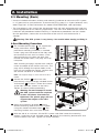 3
3
-
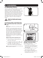 4
4
-
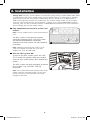 5
5
-
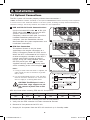 6
6
-
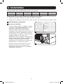 7
7
-
 8
8
-
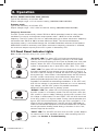 9
9
-
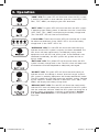 10
10
-
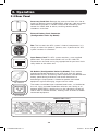 11
11
-
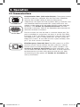 12
12
-
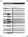 13
13
-
 14
14
-
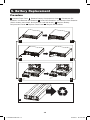 15
15
-
 16
16
-
 17
17
-
 18
18
-
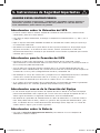 19
19
-
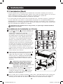 20
20
-
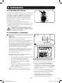 21
21
-
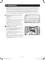 22
22
-
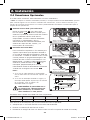 23
23
-
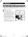 24
24
-
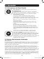 25
25
-
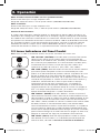 26
26
-
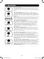 27
27
-
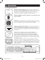 28
28
-
 29
29
-
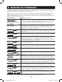 30
30
-
 31
31
-
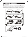 32
32
-
 33
33
-
 34
34
-
 35
35
-
 36
36
-
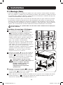 37
37
-
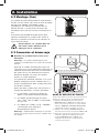 38
38
-
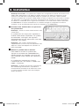 39
39
-
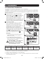 40
40
-
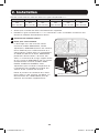 41
41
-
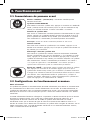 42
42
-
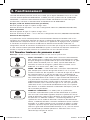 43
43
-
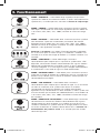 44
44
-
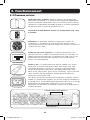 45
45
-
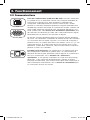 46
46
-
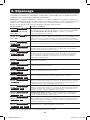 47
47
-
 48
48
-
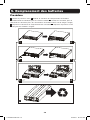 49
49
-
 50
50
-
 51
51
-
 52
52
-
 53
53
-
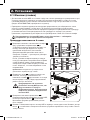 54
54
-
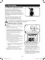 55
55
-
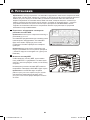 56
56
-
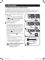 57
57
-
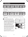 58
58
-
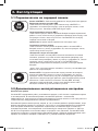 59
59
-
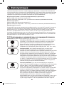 60
60
-
 61
61
-
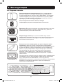 62
62
-
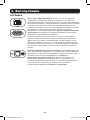 63
63
-
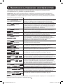 64
64
-
 65
65
-
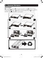 66
66
-
 67
67
-
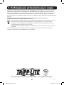 68
68


Tripp Lite SmartOnline El manual del propietario
- Tipo
- El manual del propietario
- Este manual también es adecuado para
en otros idiomas
Artículos relacionados
-
Tripp Lite SmartOnline UPS Manual de usuario
-
Tripp Lite SUINT3000RTXL2U El manual del propietario
-
-
-
-
Tripp Lite SU750XL El manual del propietario
-
-
Tripp Lite SmartOnline SU2200RTXLCD2U SU3000RTXLCD3 El manual del propietario
-
-