
MICRA-E/E6
GUIA RÁPIDA DE INSTALACIÓN
GUIDE RAPIDE D’INSTALLATION
QUICK INSTALLATION GUIDE
SCHNELL-INSTALLIERUNGSANLEITUNG
Conformidad CE. Conformité CE. CE Conformity. CE-Konformität.
Para una información más completa, por favor consulte el manual de instrucciones en nuestra web
Pour plus d'informations veuillez consultez le manuel dans nôtre site web
For complete instructions please refer to the user manual in our website
Für weitere Informationen, konsultieren Sie bitte die Bedienungsanleitung auf unserem web
Según la Directiva 2012/19/UE, no puede deshacerse de este aparato como un residuo urbano normal. Puede devolverlo, sin coste alguno, al lugar donde fue adquirido para que de esta forma se
proceda a su tratamiento y reciclado controlados.
Selon la Directive 2012/19/UE, l’utilisateur ne pout se défaire de cet appareil comme d’un residu urbain courant. Vous pouvez le restituer, sans aucun coût, au lieu où il a eté acquis afin qu’il soit
procédé à son traitement et recyclage contrôlés.
According to 2012/19/EU Directive, You cannot dispose of it at the end of its lifetime as unsorted municipal waste. You can give it back, without any cost, to the place where it was adquired to
proceed to its controlled treatment and recycling.
Gemäb der Richtlinie 2012/19/EU darf dieses Elektronikgerät nicht über den herkömlichen Haushaltsmüllkreislauf entsorgt werden. Sie kann das Gerät kostenlos an die Stelle von der es erworben
wurde, für die kontrollierte Bearbeitung und Wiederverwertung zurückgeben.
Indicador digital con entrada para:
TENSIÓN DC (±600V, ±200V , ±20V y ±2V)
CORRIENTE DC ( ±5A, ±1A, ±200mA, ±100mV, ±60mV y ±50mV)
TENSIÓN AC rms (0-600V, 0-200V, 0-20V y 0-2V)
CORRIENTE AC rms (0-5A, 0-1A, 0-200mA, 0-100mV, 0-60mV y 0-50mV)
Indicateur digitale pour signaux d’entrée:
TENSION DC (±600V, ±200V , ±20V et ±2V)
COURANT DC ( ±5A, ±1A, ±200mA, ±100mV, ±60mV et ±50mV)
TENSION AC rms (0-600V, 0-200V, 0-20V et 0-2V)
COURANT AC rms (0-5A, 0-1A, 0-200mA, 0-100mV, 0-60mV et 0-50mV)
Digital indicator for input signal:
DC VOLTAGE (±600V, ±200V and ±20V)
DC CURRENT (±5A, ±1A, ±100mV and ±60mV)
AC VOLTAGE rms(0-600V, 0-200V, 0-20V and 0-2V)
AC CURRENT rms (0-5A, 0-1A, 0-200mA, 0-100mV, 0-60mV and 0-50mV)
Digitalanzeige für Eingangssignal:
DC-SPANNUNG (±600V, ±200V und ±20V)
DC-STROM (±5A, ±1A, ±100mV und ±60mV)
AC-SPANNUNG rms (0-600V, 0-200V, 0-20V und 0-2V)
AC-STROM rms (0-5A, 0-1A, 0-200mA, 0-100mV, 0-60mV und 0-50mV)
Corriente DC. Courant DC. DC Current. DC-Strom.
Tensión DC. Tension DC. DC Voltage. DC-Spannung
* Conditions for accuracy specification
15 minutes warmup
23ºC ±5 ºC temperature range 10- 75 % R.H non condensing
Range Accuracy (*) Impedance Max Conti-
nuous Over-
load Resolution
2 V ±(0.05%R+0.3 mV) 100 kΩ 20V 0.1 mV
20 V ±(0.05%R+3 mV) 1MΩ 1000V 1 mV
200 V ±(0.05%R+30 mV) 1MΩ 1000V 10 mV
600 V ±(0.05%R+0.3 V) 1MΩ 1000V 0.1 V
Range Accuracy (*) Impedance Max Conti-
nuous Overload Resolution
200 mA ±(0.1%R+0.05 mA) 0.75 Ω 0.5A (1A-1 m) 0.01 mA
1 A ±(0.1%R+ 5 mA) 0.014 Ω 7A (10A -1m) 1 mA
5 A ±(0.1%R+ 5 mA) 0.014 Ω 7A (10A -1m) 1 mA
50 mV ±(0.1%R+0.1 mV) 1.8 MΩ 20V 0.01 mV
60 mV ±(0.1%R+0.1 mV) 1.8 MΩ 20V 0.01 mV
100 mV ±(0.1%R+0.1 mV) 1.8 MΩ 20V 0.01 mV
Corriente DC. Courant DC. DC Current. DC-Strom.
** Conditions for accuracy specification (15 minutes warmup)
23ºC ±5 ºC temperature range 10- 75 % R.H non condensing
45 Hz -400 Hz sine wave input
3 % to 100 % of range
Crest Factor: 3 Addr 0.2% + 10 digits
Crest Factor: 5 Add 1% +20 digits
40 Hz – 10 kHz: Add 1% +20 digits
Range Accuracy (*) Impedance Max Conti-
nuous Over-
load Resolution
2 V ±(0.3%R+0.3 mV) 75 kΩ 20V 0.1 mV
20 V ±(0.3%R+3 mV) 850 k Ω 1000V 1 mV
200 V ±(0.3%R+30 mV) 850 k Ω 1000V 10 mV
600 V ±(0.3%R+0.3 V) 850 k Ω 1000V 0.1 V
Range Accuracy (*) Impedance Max Conti-
nuous Overload Resolution
200 mA ±(0.3%R+0.05 mA) 0.75 Ω 0.5A (1A-1 m) 0.01 mA
1 A ±(0.3%R+ 5 mA) 0.014 Ω 7A (10A -1m) 1 mA
5 A ±(0.3%R+ 5 mA) 0.014 Ω 7A (10A -1m) 1 mA
50 mV ±(0.3%R+0.1 mV) 1.5 MΩ 20V 0.01 mV
60 mV ±(0.3%R+0.1 mV) 1.5 MΩ 20V 0.01 mV
100 mV ±(0.3%R+0.1 mV) 1.5 MΩ 20V 0.01 mV
DOWNLOAD
USER MANUAL
Tensión AC. Tension AC. AC Voltage. AC-Spannung (TRMS)
Corriente AC. Courant AC. AC Current. AC-Strom (TRMS)

p r o c n 1 n p
v d c a d c
vac
8 8 8 8
6 0 0 v 2 0 0 v 5 a 1 a 0 . 2 a
2 0 v 2 v
c n d s p s e t p a n o u t r s o u t l o g 1 n
5 t o r e
p r o
1 0 0 n v 6 0 n v
aac
5 0 n v
p r o
DIAGRAMAS DE CONFIGURACIÓN SCHÉMAS DE CONFIGURATION
SEÑAL DE ENTRADA SIGNAL D’ENTRÉE INPUT SIGNAL. EINGANGSZEICHEN
1np- 1 1np- 2
l og1n
1np- 3
8 8 8 8 8 8
p r o p r o p r o
ENTRADAS DIGITALES ENTRÉES LOGIQUES
DIGITAL INPUTS DIGITALE EINGÄNGE
Nº Function Description Activation
0 Deactivated None None
1 Deactivated None None
2 Deactivated None None
3 PEAK Displays the peak value.
(MAX.) Low level
4 VALLEY Displays the valley value.
(MIN) Low level
5 RESET
PEAK/
VALLEY
Perform a reset of the peak or
the valley, depending on which
is being displayed.
Falling edge
6 HOLD Freeze the display while all the
outputs remain active Low level
7 PRINT Sends the display value to the
printer Falling edge
8 Deactivated None None
9 Deactivated None None
10 ASCII Sends the last four digits to a
MICRA-S. Falling edge
11 BRIGHT-
NESS
Change the display brightness
from Hi to Low Low level
12 SETPOINT
VALUE
Displays the selected setpoint
value (see diagram next page) Low level
13 False
Setpoints
Simulates that the instrument
has a four setpoints option
installed
Low level
14 PRINT MAX Sends the MAX value to the
printer Falling edge
15 PRINT MIN Sends the MIN value to the
printer Falling edge
16 Remote
Keypad
The three logic inputs act as a
remote keypad * Edge
8888
c o d e
p r o
l 1 s t
t o t l c
s e t 1
s e t 2
s e t 3
s e t 4
1nput
d s p
r u n
c h a n g
----
s t o r e
spval
r s o u t
l o g 1 n
anout
s t o r e
c o l o r
r u n
p r o
s t o r e
red
green
yellow
red
green
yellow
BLOQUEO VERROUILLAGE
LOCKING VERRIEGELUNG.
Code?
0 / 1 ? ≠ - - - - ?
0 : Desbloqueado / Déverrouillé
Unlocked / Freigeschaltet
1: Bloqueado / Verrouillé
Locked / Ausgesperrt
* It’s mandatory programming the 3 logical inputs with function 16
Note: the color selection of the
alarms is made in the setpoints
menu

CONFIGURATION DIAGRAMS KONFIGURATIONSDIAGRAMME
DISPLAY. AFFICHAGE. DISPLAY. ANZEIGEN
- o n -
88888
s e t 1 s e t 2
s e t p
- o f f -
- p r o -
- n e t -
- h 1 -
- h y s -
- p r o -
88888
n o c h
s e t 3 s e t 4
g r o s
- l o -
- d l y -
8 8
a l a r n
red green amber
a l a r n a l a r n
RELÉS RELAIS RELAYS RELAYS
out h1
anout
ovrng
88888
l o
out l o
p r o 8 8 8 8 8
h 1
SALIDA ANALÓGICA SORTIE ANALOGIQUE
ANALOG OUTPUT ANALOGE AUSGABE
baud
rsout
1200
adr
p r o
8 8
2400
4800
9600
19200
t rans
1 s o
nodbus
dl y
asc11
p r o
1
2
3
4
p r o
SALIDA RS2/RS4 SORTIE RS2/RS4
RS2/RS4 OUTPUT RS2/RS4 AUSGANG
RS4 ?
1: dLY = 0 ms
2: dLY = 30 ms
3:dLY = 60 ms
4: dLY = 100 ms
SET3 / SET4
-Solo con opción
4RE, 4OP/OPP ó
función lógica #10
-Seulement avec
option 4RE, 4OP /
OPP ou fonction logi-
que # 10
-Only with option
4RE, 4OP / OPP or
logical function # 10
-Nur mit Option 4RE,
4OP / OPP oder lo-
gischer Funktion # 10
(*)
(**)
(*) Display for 10V / 20mA output
(**) Display for 0V / 4mA output
Decimal point
CndSP
tEAcHScAL FILtP round briGH Eco
InP 1
±18.888
±18888
InP 2
dSP 1
±188.88
±18.888
dSP 2
±188.88
-Pro-
InP 1
±18.888
±18888
InP 2
dSP 1
±188.88
±18.888
dSP 2
±188.88
-Pro-
8
-Pro-
88
-Pro-
-HI-
-oFF-
-Lo-
-Pro-
-on-
-Pro-
88

CN1 CN2 CN3
1 2 1 2 3 4 5 1 2 3 4
Orificio en panel
Orifice dans le pannea
Panel cutout
Schalttafel-Ausschnitt
92 x 45 mm
Estanqueidad frontal
Étanchéité du frontal
Frontal protection degree
Frontplatte Schutzart
IP65
Dimensiones y montaje
Dimensions et montage
Dimensions and mounting
Abmessungen und Montage
CN7 CN5 CN4
CN6
CN2 INPUT AC/DC CURRENT or VOLTAGE
PIN 1 = COM [AC NEUTRAL or DC(-)]
PIN 2 = SHUNT/2V [AC PHASE or DC (+) (MAX 2V)]
PIN 3 = 200mA [AC/DC 200mA (+)]
PIN 4 = 1A/5A [AC/DC Direct or CT /1A /5A]
PIN 5 = +AC/DC [AC/DC 20/200/600V PHASE or DC(+)]
WIRING and POWER SUPPLY RANGE
MICRA-E
85 V – 265 V AC 50/ 60 Hz to 100 – 300 V DC
MICRA-E6
22 – 53 V AC 50/ 60 Hz to 10,5 - 70 V DC
PIN 1: Phase / VDC PIN 2: Neutral / VDC
Recommended fuse : MICRA-E (0.5A)
MICRA-E6 (2A)
NOTE: When DC power supply, polarity in
connector CN1 is indistinct.
PIN (INPUT) Function Number
PIN 1 COMMON
PIN 2 (INP-1) PEAK Function nº 3
PIN 3 (INP-2) VALLEY Function nº 4
PIN 4 (INP-3) HOLD Function nº 6
CN3 DIGITAL INPUTS (Factory Configuration)
4 1
5 2
6 3
1
2
CN4 ANALOG OUTPUT SIGNAL
4-20mA (OPTION)
PIN 1 = (-) [4-20 mA]
PIN 2 (+) [4-20 mA]
0-10V (OPTION)
PIN 1 = (-) [0-10V]
PIN 2 = (+) [0-10V]
CN6 / CN7 RELAIS OUTPUT
2RE OPTION 4RE OPTION 4OP/4OPP OPTION
.
PIN 1 = NO1
PIN 2= COMM1
PIN 3 = NC1
PIN 4 = NO2
PIN 5 = COMM2
PIN 6 = NC2
PIN 1 = RL1
PIN 2= RL2
PIN 3 = RL3
PIN 4 = RL4
PIN 5 = N/C
PIN 6 = COMMON
PIN 1 = OPTO1
PIN 2 = OPTO2
PIN 3 = OPTO3
PIN 4 = OPTO4
PIN 5 = N/C
PIN 6 = COMMON
Fusible Relé recomendado :
Fusible Relais recommandé :
Recommended Relais fuse :
Empfohlene Sicherungrelais :
** IMPORTANTE! / IMPORTANT! / WICHTIG!
Para garantizar la seguridad eléctrica de acuerdo con EN
61010-1 deberá instalarse como medida de protección un
fusible externo.
Pour garantir le sécurité électrique selon EN 61010-1 il faut
installer un fusible externe de protection.
To guarantee electrical safety according to EN 61010-1 a
protective external fuse must be installed.
Um die elektrische Sicherheit nach EN 61010-1 zu
garantieren, muss eine externe Sicherung installiert werden.
20220823
DISEÑOS Y TECNOLOGÍA, S.A.
Xarol, 6B P.I. Les Guixeres
08915 Badalona (Barcelona) - Spain
Tel. +34 933 394 758
Fax +34 934 903 145
Email: comercial@ditel.es ; web: www.ditel.es
Nota: Para obtener información adicional sobre el cableado,
descargue el manual completo de nuestro sio web
Remarque: Pour plus d'informaons sur le câblage, téléchar-
gez le manuel complet sur notre site Web
Note: For addional wiring informaon download complete
manual from our website
Hinweis: Für zusätzliche Informaonen zur Verkabelung laden
Sie das vollständige Handbuch von unserer Website herunter
(2RE = 8A / 4RE = 5A)
CONEXIONADO RACCORDEMENT CONNECTIONS ANSCHLÜSSE
CN2
1 2 3 4 5
N
L
V
Voltmeter 20/ 200/ 600 V
DC/ AC
CN2
1 2 3 4 5
V
N
L
Voltmeter 2 V
DC/ AC
CN2
1 2 3 4 5
I
N
L
Ammeter 200 mA
DC/ AC
CN2
1 2 3 4 5
I
N
L
Ammeter 1/ 5 A
DC/ AC
CN2
1 2 3 4 5
I
N
L
Ammeter with Transformer
1 A or 5 A
CN2
1 2 3 4 5
I
SHUNT
N
L
Ammeter with
Shunt
50/ 60/ 100 mV
-
 1
1
-
 2
2
-
 3
3
-
 4
4
en otros idiomas
- français: Ditel MICRA-E
- English: Ditel MICRA-E
- Deutsch: Ditel MICRA-E
Artículos relacionados
-
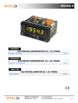 Ditel MICRA-E Technical Manual
-
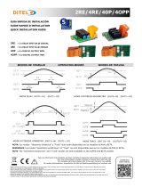 Ditel 2RE-4RE-4OP-4OPP Quick Start
-
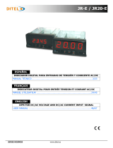 Ditel JR-E / JR20-E Technical Manual
-
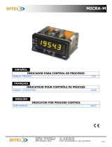 Ditel MICRA-M Technical Manual
-
 Ditel MICRA-D Technical Manual
-
 Ditel PICA100-P / PICA101-P / PICA104-P Technical Manual
-
Ditel ALPHA-C Quick Start
-
 Ditel ALPHA-D Technical Manual
-
 Ditel GAMMA-M Technical Manual
-
 Ditel ALPHA-P Technical Manual


