
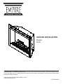
Installation Guide
Model
EF39
IMPORTANT SAFETY INFORMATION: Always read this manual rst before attempting to install or use this replace. For
your safety, always comply with all warnings and safety instructions contained in this manual to prevent personal injury or
property damage.
To view the full line of Empire products, please visit
www.empirecomfort.com
7206350600R01

2
www.empirecomfort.com
Listing and Code Approvals ..........................................................3
Model Specications. . . . . . . . . . . . . . . . . . . . . . . . . . . . . . . . . . . . . . . . . . . . . . . . . . . . . . . . . . . . . . . .3
Step-by-Step Installation . . . . . . . . . . . . . . . . . . . . . . . . . . . . . . . . . . . . . . . . . . . . . . . . . . . . . . . . . . . .3
Section A: Installation information ....................................................4
Framing Dimensions . . . . . . . . . . . . . . . . . . . . . . . . . . . . . . . . . . . . . . . . . . . . . . . . . . . . . . . . . . . . . . .4
Mounting Flanges .................................................................4
Section B: General Electrical Information. . . . . . . . . . . . . . . . . . . . . . . . . . . . . . . . . . . . . . . . . . . . . . .5
Recommended Power Supply Wire Specications . . . . . . . . . . . . . . . . . . . . . . . . . . . . . . . . . . . . . . . .5
Voltage Selector Switch Location .....................................................5
Section C: Direct Power Wiring .......................................................6
240V Installation ..................................................................6
120V Installation ..................................................................6
120V Installation - No Heat Installation . . . . . . . . . . . . . . . . . . . . . . . . . . . . . . . . . . . . . . . . . . . . . . . . .7
Section D: Alternate Control Options ..................................................8
240V Main Power Wall Switch .......................................................8
120V Main Power Wall Switch .......................................................9
120V Main Power Wall Switch - No Heat ..............................................10
120V/240V Heater Wall Switch Control. . . . . . . . . . . . . . . . . . . . . . . . . . . . . . . . . . . . . . . . . . . . . . . .11
120V/240V Wall Mounted Thermostat. . . . . . . . . . . . . . . . . . . . . . . . . . . . . . . . . . . . . . . . . . . . . . . . .12
120V/240V Wall Mounted Flame Override Switch .......................................13
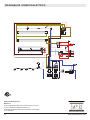
Unit Internal Wiring Diagram ........................................................14
!
NOTE: Procedures and techniques that are consid-
ered important enough to emphasize.
CAUTION: Procedures and techniques which, if not
carefully followed, will result in damage to the equipment.
WARNING: Procedures and techniques which, if not
carefully followed, will expose the user to the risk of
re, serious injury, or death.
Table of Contents

3
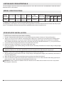
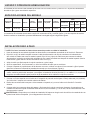
The EF39 replace has been tested in accordance with the UL 2021 and CSA C22.2 No. 46 standards for xed and location-
dedicated electric room heaters.
Model
Number
Description Voltage
Rated
Power
(Watts)
Remote
Control
Wall
Thermostat
Refractory
Brick Look
Current Draw (Amps)
No Heat
120V
120V 208V 240V
EF39 39" Deluxe
120/120/
208/240
245/1440/
2100/2700
Optional Optional Included 2.0 12.0 10.10 11.25
!
NOTE: Power ratings shown include the light bulbs and motors (275 watts)
The installation of the fireplace unit must comply with the applicable Local and/or National Electrical Codes and utility require-
ments. This installation should be entrusted to duly qualified personnel where required by law.
MODEL SPECIFICATIONS
!
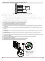
NOTE: Please read all instructions before installing.
1. Rough in framing opening following the recommended dimensions located in Section A: Framing Dimensions.
2. Allow 8" (20.3 cm) of service cable for connecting power supply wire to junction box on replace when installing before
nishing wall. Allow up to 4' (121.9 cm) of service cable for connecting power supply wire to junction box on replace
when installing after nishing wall. Remove the outer jacket and strip the individual conductors ½" (1.3 cm) from the end.
3. Loosen the screw securing the junction box cover and remove the cover.
4. Remove knockouts, if necessary, or use the provided cable clamp.
5. Place unit in position in the framed opening, level with shims if necessary and attach unit to frame using mounting anges
provided (Figure 2).
6. Unit is factory wired for 208/240V power supply. If 120V operation is required, slide the switch and recongure the wiring
(Section C). Wires L1, L2, N & G are attached to the rear of the junction box cable clamp for easy access.
!
NOTE: If wiring unit to operate with NO heat a dedicated circuit may not be required.
7. Wire a dedicated, properly fused circuit with a 15amp rating for the appropriate voltage (120V, 208/240V). See Section C
for factory setting wiring.
8. Make wall switch and or wall mounted thermostat connections as outlined in Section D.
9. Place all connectors inside the unit and secure the junction box cover to unit. Ensure that the cable clamp grips only the
jacket of service cable, thermostat and if applicable wall switch lines.
WARNING: Ensure method of installation does NOT obscure the air intake slots on bottom front of unit in any manner.
(See diagram in Section A)
STEP-BY-STEP INSTALLATION
LISTING AND CODE APPROVALS

4
www.empirecomfort.com
J
K
L
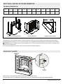
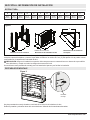
FRAMING DIMENSIONS
Rough-In Framing Dimensions Firebox Dimensions Rough-In Corner Framing
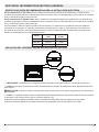
This replace is a zero clearance design, with the exception of the top of the unit, where any insulation and vapor barrier
should be placed a minimum of 2" (5.1 cm) from the unit. No combustibles can be placed on the top surface of the replace.
CAUTION: Ensure installation does not allow replace to be in direct contact with building vapor barrier or insulation and
meets all local building code.
Four mounting anges on the sides of the unit are provided to facilitate installation.
MOUNTING FLANGES
SECTION A: INSTALLATION INFORMATION
Figure 1
Figure 2
A
B
-0 / +0.1
C
-0 / +0.1
D E F G H I J K L
16.0"
(40.5cm)
39"
(99.1cm)
32.9"
(83.6cm)
30.1"
(76.5cm)
15.3"
(38.9cm)
36.0"
(91.4cm)
38.7"
(98.3cm)
22.8"
(57.9cm)
32.7"
(83.1cm)
54.0"
(137.2cm)
38.0"
(96.5cm)
38.0"
(96.5cm)
Air Intake Slots
There are two mounting anges located on each side of the replace insert.
From the inside of the unit, bend tabs outward and mount to the inside of the framing using suitable hardware.
Mounting
Flanges

5
SECTION B: GENERAL ELECTRICAL INFORMATION
For 120V installations use two conductor, non-metallic sheath cable with ground wire (3 wires total) for the incoming power
supply on replace inserts. Use the appropriate wire to meet local and national electrical codes for rated power consumption.
For 208V / 240V installations use three conductor, non-metallic sheath cable with ground wire (4 wires total) for the incom-
ing power supply on replace inserts. Use the appropriate wire to meet local and national electrical codes for rated power
consumption.
Two conductor, non-metallic sheath cable with ground wire (3 wires total) is recommended for installation of a wall mounted
thermostat and/or wall switch for use on replace inserts. Use appropriate wire to meet local and national electrical codes for
rated power consumption. All wire gauges should match the recommended wire sizes shown below.
Voltage Wire Gauge Fuse Rating
120 Volts 14 Gauge 15 Amp
208 Volts 14 Gauge 15 Amp
240 Volts 14 Gauge 15 Amp
RECOMMENDED POWER SUPPLY WIRE SPECIFICATIONS
!
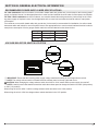
IMPORTANT: Ensure that the incoming power supply voltage matches the setting of the voltage selector switch.
!
NOTE: The voltage selector switch is located inside the exhaust panel on the top right hand corner.
CAUTION: When changing the voltage selector switch from 240V to 120V ensure that the power supply is turned o.
!
NOTE: Carefully insert a at headed screwdriver inside the exhaust panel to change the switch from 240V (230 position)
to 120V (115 position).
When wiring the unit for 208V / 240V the voltage selector switch should be in the 230V position.
When wiring the unit for 120V the voltage selector switch should be in the 115V position.
VOLTAGE SELECTOR SWITCH LOCATION

6
www.empirecomfort.com
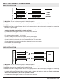
!
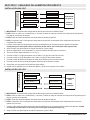
IMPORTANT: The unit is factory congured for 208/240V operation.
!
NOTE:
Use 3 conductor wires with ground (4 wires total) from the power supply (breaker panel) to the junction box on the unit.
!
NOTE: All wiring must be completed prior to installing the unit.
!
NOTE: Ensure that the voltage selector switch is in the proper position for the required supply voltage prior to connecting
the unit to the power supply.
1. Locate the voltage selector switch inside the exhaust panel on the top right hand corner of the unit. Ensure that the
switch is in the 240V position. (230 is printed on switch)
2. Loosen the screw securing the junction box cover and remove the cover.
3. Remove the knockouts (if necessary) or use the provided cable clamp.
4. Pull out the four wires marked L1, L2, N, and G.
5. Connect L1 (black) from the unit to the L1 (black) from the power supply.
6. Connect L2 (red) from the unit to the L2 (red) from the power supply.
7. Connect N (white) from the unit to the to the Neutral (white) from the power supply.
8. Connect the ground wire (green) from the unit to the ground from the power supply.
9. Ensure that all connections are tight.
10. Insert all the wiring back into the unit and secure with a cable clamp.
240 V
POWER
SUPPLY
(BREAKER
PANEL)
FIREPLACE JUNCTION BOX
WHITE WIRE - N
RED WIRE – L2
BLACK WIRE – L1
GREEN WIRE - G
WHITE WIRE - N
RED WIRE – L2
BLACK WIRE – L1
GROUND WIRE - G
SECTION C: DIRECT POWER WIRING
240V INSTALLATION
!
IMPORTANT: The unit is factory congured for 208/240V operation.
!
NOTE:
Use 2 conductor wires with ground (3 wires total) from the power supply (breaker panel) to the junction box on the unit.
!
NOTE: All wiring must be completed prior to installing the unit.
!
NOTE: Ensure that the voltage selector switch is in the proper position for the required supply voltage prior to connecting
the unit to the power supply.
1. Locate the voltage selector switch inside the exhaust panel on the top right hand corner of the unit. Flip the switch from
240V to 120V conguration. (230 and 115 is printed on switch)
2. Loosen the screw securing the junction box cover and remove the cover.
FIREPLACE JUNCTION BOX
120 V
POWER
SUPPLY
(BREAKER
PANEL)
WHITE WIRE - N
RED WIRE – L2
BLACK WIRE – L1
WHITE WIRE - N
BLACK WIRE – L1
GROUND WIRE - G
GREEN WIRE - G
120V INSTALLATION

7
3. Remove the knockouts (if necessary) or use the provided cable clamp.
4. Pull out the four wires marked L1, L2, N, and G.
5. Connect L1 (black) wire from the unit to the L1 (black) from the power supply.
6. Connect L2 (red) and N (white) from the unit to the Neutral (white) from the power supply.
7. Connect the ground wire (green) from the unit to the ground from the power supply.
8. When the unit has been congured for the appropriate power supply voltage, ensure that all connections are tight.
9. Insert all the wiring back into the unit and secure with a cable clamp.
!
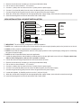
IMPORTANT: The unit is factory congured for 208/240V operation.
!
NOTE:
Use 2 conductor wires with ground (3 wires total) from the power supply (breaker panel) to the junction box on the unit.
!
NOTE: All wiring must be completed prior to installing the unit.
!
NOTE: Ensure that the voltage selector switch is in the proper position for the required supply voltage prior to connecting
the unit to the power supply.
!
NOTE: the fan will operate without heat in this application.
1. Locate the voltage selector switch inside the exhaust panel on the top right hand corner of the unit. Flip the switch from
240V to 120V conguration. (230 and 115 is printed on switch)
2. Loosen the screw securing the junction box cover and remove the cover.
3. Remove the knockouts (if necessary) or use the provided cable clamp.
4. Pull out the four wires marked L1, L2, N, and G.
5. Connect L1 (black) wire from the unit to the L1 (black) from the power supply.
6. Connect L2 (red) and N (white) from the unit to the Neutral (white) from the power supply.
7. Connect the ground wire (green) from the unit to the ground from the power supply.
8. Locate and separate, by installing a wire nut on the 1 (red) and 2 (red).
9. When the unit has been congured for the appropriate power supply voltage, ensure that all connections are tight.
10. Insert all the wiring back into the unit and secure with a cable clamp.
FIREPLACE JUNCTION BOX
120 V
POWER
SUPPLY
(BREAKER
PANEL)
WHITE WIRE - N
RED WIRE – L2
BLACK WIRE – L1
GREEN WIRE - G
WHITE WIRE - N
BLACK WIRE – L1
GROUND WIRE - G
RED - 1
RED - 2
WIRE NUTS
120V INSTALLATION - NO HEAT INSTALLATION

8
www.empirecomfort.com
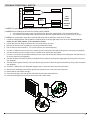
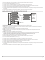
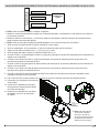
SECTION D: ALTERNATE CONTROL OPTIONS
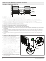
240V MAIN POWER WALL SWITCH
!
NOTE: This option should not be used with the remote control kit.
!
NOTE: Before installing the unit have the following wires installed:
1. A 3 conductor wire with ground (4 wires total) from the power supply panel to the main switch wall box.
2. A 3 conductor wire with ground (4 wires total) from the main switch wall box to the junction box on the unit.
!
NOTE: Use a double pole, single throw (On/O) wall switch that is rated for a minimum of 15 amps.
1. Locate the voltage selector switch inside the exhaust panel on the top right hand corner of the unit. Ensure that the
switch is in the 240V position. (230 is printed on switch)
2. Loosen the screw securing the junction box cover and remove the cover.
3. Remove the knockouts (if necessary) or use the provided cable clamp.
4. Pull out the four wires marked L1, L2, N, and G. (black, red, white and green)
5. Connect the L1 (black) wire from the unit to the L1 (black) wire from the main power wall switch by using a wire connector
(not supplied).
6. Connect other end of L1 (black) wire from the main power wall switch to the L1 terminal of the main power wall switch.
7. Connect the L2 (red) wire from the unit to the L2 (red) wire from the main power wall switch by using a wire connector
(not supplied).
8. Connect the other end of the L2 (red) wire from the main power wall switch to the L2 terminal of the main power wall
switch.
9. Connect the N (white) wire from the unit to the N
(white) wire from the main power wall switch by
using a wire connector (not supplied).
10. Connect the G (green) wire from the unit to the G
(green) wire from the main power wall switch by
using a wire connector (not supplied).
11. Connect the L1 wire from the power supply to the
L1 terminal of the main power wall switch.
12. Connect the L2 (black) wire from the power
supply to the L2 terminal of the main power wall
switch.
13. Connect the N (white) wire from the power supply
to the remaining N (white) wire from the unit by
using a wire connector.
14. Secure the 2 remaining G (green) wires with a
ground screw in the main switch wall box.
15. Ensure that all connections are tight.
16. Insert all the wiring of the main power wall switch
into the main switch wall box.
17. Insert all the wiring back into the unit and secure
with a cable clamp.
UNIT AND SUPPLY
NEUTRAL FROM
G FROM UNIT
POWER SUPPLY
G FROM
L1 FROM
POWER SUPPLY
POWER SUPPLY
L2 FROM
L1 FROM UNIT
G
L1
L2 FROM UNIT
N
L2
3 CONDUCTOR WIRE
FROM POWER SUPPLY
3 CONDUCTOR WIRE
FROM MAIN SWITCH
UNIT AND SUPPLY
NEUTRAL FROM
L2 FROM UNIT
L1 FROM UNIT
L2 FROM
POWER SUPPLY
POWER SUPPLY
L1 FROM
G FROM
POWER SUPPLY
G FROM UNIT
G
L2
N
L1
FIREPLACE JUNCTION BOX
240 V
POWER
SUPPLY
(BREAKER
PANEL)
WHITE - N
RED – L2
BLACK – L1
WHITE – N
BLACK – L1
GROUND - G
WALL
SWITCH
RED – L2
GROUND - G

9
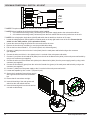
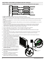
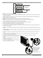
120V MAIN POWER WALL SWITCH
FIREPLACE JUNCTION BOX
120 V
POWER
SUPPLY
(BREAKER
PANEL)
WHITE - N
RED – L2
BLACK – L1
WHITE – N
BLACK – L1
GROUND - G
WALL
SWITCH
GROUND - G
!
NOTE: This option should not be used with the remote control kit.
!
NOTE: Before installing the unit have the following wires installed:
1. A 2 conductor wire with ground (3 wires total) from the power supply panel to the main switch wall box.
2. A 2 conductor wire with ground (3 wires total) from the main switch wall box to the junction box on the unit.
!
NOTE: Use a single pole, single throw (On/O) wall switch that is rated for a minimum of 15 amps.
1. Locate the voltage selector switch inside the exhaust panel on the top right hand corner of the unit. Ensure that the
switch is in the 120V position. (115 is printed on switch)
2. Loosen the screw securing the junction box cover and remove the cover.
3. Remove the knockouts (if necessary) or use the provided cable clamp.
4. Pull out the four wires marked L1, L2, N, and G (black, red, white and green).
5. Connect L1 (black) from the unit to the L1 (black) from the main power wall switch using a wire connector (not supplied).
6. Connect the other end of L1 (black) to the L1 terminal of the main power wall switch.
7. Connect L2 (red) from the unit and N (white) from the unit to the Neutral wire (white) of the main power wall switch by us-
ing a wire connector (not supplied).
8. Connect the other end of the N (white) to the Neutral wire (white) from the power supply panel by using a wire connector
(not supplied).
9. Connect Ground (green) from the unit to the Ground (green) wire of the main power wall switch by using a wire connector
(not supplied).
10. Connect L1 (black) wire from the power supply to the L1 terminal of the main power wall switch.
11. Secure the 2 remaining Ground wires (green) with a ground screw in the main switch wall box.
12. Ensure that all connections are tight.
13. Insert all the wiring of the main power wall switch into the main switch wall box.
14. Insert all the wiring back into the unit and secure with a cable clamp.
FROM MAIN SWITCH
2 CONDUCTOR WIRE
FROM POWER SUPPLY
2 CONDUCTOR WIRE
L2
N
L1
G
L1 FROM UNIT
G FROM
POWER SUPPLY
G FROM UNIT
L1 FROM
POWER SUPPLY
NEUTRAL FROM
UNIT AND SUPPLY
UNIT AND SUPPLY
NEUTRAL FROM
POWER SUPPLY
L1 FROM
G FROM UNIT
POWER SUPPLY
G FROM
L1 FROM UNIT
G
L1
N
L2

10
www.empirecomfort.com
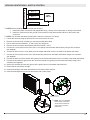
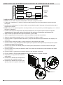
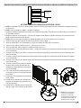
!
NOTE: This option should not be used with the remote control kit.
!
NOTE: Before installing the unit have the following wires installed:
1. A 2 conductor wire with ground (3 wires total) from the power supply panel to the main switch wall box.
2. A 2 conductor wire with ground (3 wires total) from the main switch wall box to the junction box on the unit.
!
NOTE: Use a single pole, single throw (On/O) wall switch that is rated for a minimum of 15 amps.
1. Locate the voltage selector switch inside the exhaust panel on the top right hand corner of the unit. Ensure that the
switch is in the 120V position. (115 is printed on switch)
2. Loosen the screw securing the junction box cover and remove the cover.
3. Remove the knockouts (if necessary) or use the provided cable clamp.
4. Pull out the four wires marked L1, L2, N, and G (black, red, white and green).
5. Connect L1 (black) from the unit to the L1 wire (black) from the main power wall switch using a wire connector
(not supplied).
6. Connect the other end of the L1 wire (black) to the L1 terminal of the main power wall switch.
7. Connect L2 (red) from the unit and the N (white) from the unit to the Neutral wire (white) of the main power wall switch by
using a wire connector (not supplied).
8. Connect the other end of the Neutral wire (white) to the Neutral wire (white) from the power supply panel by using a wire
connector (not supplied).
9. Connect the Ground wire (green) from the unit to the Ground wire (green) of the main power wall switch by using a wire
connector (not supplied).
10. Connect L1 (black) from the power supply to the L1 terminal of the main power wall switch.
11. Locate and separate by wire nut the 1 (red) and 2 (red).
12. Secure the 2 remaining Ground wires (green)
with a ground screw in the main switch wall
box.
13. Ensure that all connections are tight.
14. Insert all the wiring of the main power wall
switch into the main switch wall box.
15. Insert all the wiring back into the unit and se-
cure with a cable clamp.
FIREPLACE JUNCTION BOX
120 V
POWER
SUPPLY
(BREAKER
PANEL)
WHITE - N
RED – L2
BLACK – L1
WHITE – N
BLACK – L1
GROUND - G
WALL
SWITCH
GROUND - G
RED – 1
RED – 2
WIRE
NUTS
120V MAIN POWER WALL SWITCH - NO HEAT
FROM MAIN SWITCH
2 CONDUCTOR WIRE
FROM POWER SUPPLY
2 CONDUCTOR WIRE
L2
N
L1
G
L1 FROM UNIT
G FROM
POWER SUPPLY
G FROM UNIT
L1 FROM
POWER SUPPLY
NEUTRAL FROM
UNIT AND SUPPLY
UNIT AND SUPPLY
NEUTRAL FROM
POWER SUPPLY
L1 FROM
G FROM UNIT
POWER SUPPLY
G FROM
L1 FROM UNIT
G
L1
N
L2
1
2

11
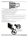
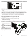
!
NOTE: Before installing the unit complete the following:
1. Install main power connection with appropriate wiring - directly to the main power or through a wall switch.
2. Install a 2 conductor wire with ground (3 wires total) from the heater switch wall box to the junction box
on the unit.
!
NOTE: Use a heater wall switch (On/O) that is rated for a minimum of 15 amps.
1. Loosen the screw securing the junction box cover and remove the cover.
2. Remove the knockouts (if necessary) or use the provided cable clamp.
3. Pull out the three wires marked 1, 2, and G (red, red, and green).
4. Remove the wire connector and separate the wires marked 1 and 2.
5. Connect the 1 wire (red) from the unit to the L1 wire (black) from the heater wall switch by using a wire connector
(not supplied).
6. Connect the other end of L1 wire (black) from the heater wall switch to the L1 terminal of the heater wall switch.
7. Connect the 2 wire (red) from the unit to the Neutral wire (white) from the heater wall switch using a wire connector
(not supplied).
8. Connect the other end of the Neutral wire (white) from the heater wall switch to the L2 terminal of the heater wall switch.
9. Connect the Ground wire (green) from the unit to the Ground wire (green) from the heater wall switch using a wire
connector (not supplied).
10. Secure the remaining Ground wire (green) with a ground screw in the heater switch wall box.
11. Ensure that all connections are tight.
12. Insert all the wiring of the heater wall switch into the heater switch wall box.
13. Insert all the wiring back into the unit and secure with a cable clamp.
120V/240V HEATER WALL SWITCH CONTROL
FIREPLACE JUNCTION BOX
RED – 2
WALL
SWITCH
RED – 1
GROUND - G
G
L1 FROM UNIT
G FROM
POWER SUPPLY
G FROM UNIT
L1 FROM
POWER SUPPLY
NEUTRAL FROM
UNIT AND SUPPLY
UNIT
WIRE 1 FROM
G FROM UNIT
WIRE 2 FROM
G
2
1
2 CONDUCTOR WIRE
UNIT
FROM HEATER SWITCH
2
1
!
NOTE: This only illustrates
heater switch connection,
see previous sections for
main power connection
instructions.

12
www.empirecomfort.com
120V/240V WALL MOUNTED THERMOSTAT
!
NOTE: Before installing the unit complete the following:
1. Install main power connection with appropriate wiring - directly to the main power or through a wall switch.
2. Install a 2 conductor wire with ground (3 wires total) from the thermostat wall box to the junction box on the unit.
!
NOTE: Wiring of the thermostat must be completed prior to installing the unit.
!
NOTE: The following installation instructions are for a single pole thermostat.
1. Loosen the screw securing the junction box and remove the cover.
2. Remove the knockouts (if necessary) or use the provided cable clamp.
3. Pull out the three wires marked 1, 2, and G (red, red, and green).
4. Remove the wire connector and separate the wires marked 1 & 2.
5. Connect the 1 wire (red) from the unit to the Neutral (white) wire from the wall thermostat box by using a wire connector
(not supplied).
6. Connect the other end of the Neutral (white) wire from the thermostat wall box to the red wire from the wall thermostat.
7. Connect the 2 wire (red) from the unit to the black wire from the thermostat wall box by using a wire connector
(not supplied).
8. Connect the other end of the black wire from the thermostat wall box to the black wire from the wall thermostat.
9. Connect the Ground wire (green) from the unit to the Ground (green) wire from the thermostat wall box by using a wire
connector (not supplied).
10. Connect the other end of the Ground wire (green) to the thermostat wall box ground screw.
11. Ensure that all connections are tight.
12. Insert all the wiring of the wall mounted thermostat into the wall box.
13. Insert all the wiring back into the unit and secure with a cable clamp.
FIREPLACE JUNCTION BOX
WALL
THERMOSTAT
RED – 1
GROUND - G
RED – 2
BLACK
RED
GROUND
GROUND
2
1
GROUND
RED
BLACK
BLACK WIRE
WHITE WIRE
GROUND
SCREW
G
1
2
GROUND
G
!
NOTE: This only illustrates
thermostat connection, see
previous sections for main
power connection instruc-
tions.

13
120V/240V WALL MOUNTED FLAME OVERRIDE SWITCH
DO NOT USE WITH NO HEAT INSTALLATIONS
!
NOTE: The replace can be wired to have a wall switch operate the ame independent of the heater.
!
NOTE: Before installing the unit complete the following:
1. Install main power connection with appropriate wiring - directly to the main power or through a wall switch.
2. Install a 2 conductor wire with ground (3 wires total) from the ame override switch wall box to the junction box
on the unit.
!
NOTE: Use a wall switch (On/O) that is rated for a minimum of 15 amps.
1. Loosen the screw securing the junction box cover and remove the cover.
2. Remove the knockouts (if necessary) or use the provided cable clamp.
3. Pull out the three wires marked 3, 4, and G (blue, blue, and green).
4. Remove the wire connector and separate the wires marked 3 and 4.
5. Connect 3 wire (blue) from the unit to the L1 wire (black) from the ame override wall switch by using a wire connector
(not supplied).
6. Connect the other end of the L1 wire (black) from the ame override wall switch to the L1 terminal of the ame override
wall switch.
7. Connect 4 wire (blue) from the unit to the Neutral wire (white) from the ame override wall switch using a wire connector
(not supplied).
8. Connect the other end of the Neutral wire (white) from the ame override wall switch to the L2 terminal of the ame
override wall switch.
9. Connect the Ground wire (green) from the unit to the Ground wire (green) from the ame override wall switch using a wire
connector (not supplied).
10. Secure the remaining Ground wire (green) with a ground screw in the ame override switch wall box.
11. Ensure that all connections are tight.
12. Insert all the wiring of the heater wall switch into the heater switch wall box.
13. Insert all the wiring back into the unit and secure with a cable clamp.
FIREPLACE JUNCTION BOX
BLUE – 4
WALL
SWITCH
BLUE – 3
GROUND - G
UNIT
FROM FLAME OVERRIDE SWITCH
2
1
G
L1 FROM UNIT
G FROM
POWER SUPPLY
G FROM UNIT
L1 FROM
POWER SUPPLY
NEUTRAL FROM
UNIT AND SUPPLY
UNIT
WIRE 3 FROM
G FROM UNIT
WIRE 4 FROM
G
4
3
2 CONDUCTOR WIRE
!
NOTE: This only illustrates
ame switch connection,
see previous sections for
main power connection
instructions.

14
www.empirecomfort.com
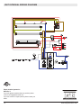
UNIT INTERNAL WIRING DIAGRAM
Empire Comfort Systems Inc.
Belleville, IL
If you have general questions about our products, please
e-mail us at [email protected].
If you have a service or repair question, please contact your
dealer.

GUÍA DE INSTALACIÓN
Modelo
EF39
INFORMACIÓN DE SEGURIDAD IMPORTANTE: Lea este manual antes de intentar instalar o usar este calentador de aire.
Para su seguridad, tome en cuenta todas las advertencias e instrucciones de seguridad de este manual para evitar lesiones
corporales o daños materiales.
Para ver toda la línea de productos Empire, visite
www.empirecomfort.com
7206350600R01

2
www.empirecomfort.com
Listado y códigos de homologación . . . . . . . . . . . . . . . . . . . . . . . . . . . . . . . . . . . . . . . . . . . . . . . . . . .3
Especicaciones del modelo . . . . . . . . . . . . . . . . . . . . . . . . . . . . . . . . . . . . . . . . . . . . . . . . . . . . . . . . .3
Instalación paso a paso . . . . . . . . . . . . . . . . . . . . . . . . . . . . . . . . . . . . . . . . . . . . . . . . . . . . . . . . . . . . .3
Sección A: Información de instalación . . . . . . . . . . . . . . . . . . . . . . . . . . . . . . . . . . . . . . . . . . . . . . . . .4
Estructura .......................................................................4
Pestañas de montaje. . . . . . . . . . . . . . . . . . . . . . . . . . . . . . . . . . . . . . . . . . . . . . . . . . . . . . . . . . . . . . .4
Sección B: Información eléctrica general. . . . . . . . . . . . . . . . . . . . . . . . . . . . . . . . . . . . . . . . . . . . . . .5
Especicaciones recomendadas para la instalación eléctrica . . . . . . . . . . . . . . . . . . . . . . . . . . . . . . .5
Ubicación del interruptor de selección del voltaje ........................................5
Sección C: Cableado de alimentación directa ...........................................6
Instalación 240 Volt . . . . . . . . . . . . . . . . . . . . . . . . . . . . . . . . . . . . . . . . . . . . . . . . . . . . . . . . . . . . . . . .6
Instalación 120 Volt . . . . . . . . . . . . . . . . . . . . . . . . . . . . . . . . . . . . . . . . . . . . . . . . . . . . . . . . . . . . . . . .6
Instalación 120 Volt - sin instalación de calor ............................................7
Sección D: Opciones alternativas de control . . . . . . . . . . . . . . . . . . . . . . . . . . . . . . . . . . . . . . . . . . . .8
Instalación 240V de alimentación principal de interruptor de pared . . . . . . . . . . . . . . . . . . . . . . . . . . .8
Instalación 120V de alimentación principal de interruptor de pared . . . . . . . . . . . . . . . . . . . . . . . . . . .9
Instalación 120V de alimentación principal de interruptor de pared - sin instalación de calor ......10
Calentador de pared Interruptor de Control para las instalaciones de 120/240 voltios ...........11
Conexión del termostato de pared para las instalaciones de 120/240 voltios ..................12
Montado en la pared Flame conmutador de anulación para las instalaciones de 120/240 voltios . . .13
Diagrama de conexión eléctrica. . . . . . . . . . . . . . . . . . . . . . . . . . . . . . . . . . . . . . . . . . . . . . . . . . . . . .14
!
NOTA: Procedimientos y técnicas que se considera
importante destacar.
PRECAUCIÓN: En caso de no seguir los
procedimientos y técnicas cuidadosamente, se dañará
el equipo.
ADVERTENCIA: Procedimientos y técnicas que, en
caso de no seguirse cuidadosamente, expondrán al
usuario a riesgo de incendio, lesión grave o muerte.
Índice

3
El calentador de aire EF39 ha sido testados de acuerdo con las normas UL 2021 y CSA C22.2 nº 46 para los calentadores
domésticos jos y para una ubicación especíca.
Número de
Modelo
Descripción Voltios
Vatios
nominales
Control
remoto
Termostato
de pared
Ladrillo
refractario
AMP.
Sin
calefacción
120 voltios
120
voltios
208
voltios
240
voltios
EF39 39" de lujo
120/120/
208/240
245/1440/
2100/2700
Opcional Opcional Incluido 2.0 12.0 10.10 11.25
!
NOTA: Las potencias nominales indicadas incluyen las bombillas y el motor (275 W).
La instalación del calentador de aire debe cumplir con la normativa local y nacional vigente, y con los requisitos de servicio.
Debería confiarse su instalación a personal debidamente homologado según la legislación vigente.
ESPECIFICACIONES DEL MODELO
LISTADO Y CÓDIGOS DE HOMOLOGACIÓN
!
NOTA: Por favor, lea todas las instrucciones antes de proceder a realizar la instalación.
1. Hacer la abertura de encuadrado siguiendo las dimensiones recomendadas que hallarán en la Sección A: Estructura.
2. Deje 20,3 cm (8") de cable fuera para conectar el cable de alimentación a la caja de conexiones del calentador de
aire cuando se instale éste antes de acabar la pared. Deje 122 cm (4 pies) de cable fuera para conectar el cable de
alimentación a la caja de conexiones del calentador de aire cuando se instale éste después de acabar la pared. Quite la
funda exterior y pele cada uno de los conductores unos 12 mm (½").
3. Aoje el tornillo que ja la tapa de la caja de conexiones y quite la tapa.
4. Quite los separadores, si fuera necesario, o utilice la mordaza del cable que se suministra.
5. Coloque el aparato en posición dentro de la abertura con marco, nivélelo con calzos si fuera necesario y je el aparato
dentro de la estructura utilizando las pestañas de montaje que se suministran (Figura 2).
6. El aparato lleva una conexión eléctrica de fábrica para una toma de 208/240 voltios. Si se necesita que funcione con 120
voltios, cambie la posición del interruptor y recongure la instalación eléctrica (Sección C). Los cables L1, L2, N y G son
fácilmente accesibles desde la parte posterior de la abrazadera de los cables en la caja de conexiones.
!
NOTA: Si el aparato de conexión va a funcionar SIN calor, no es necesario un circuito especial.
7. Conecte un circuito especial con un fusible de 15 amperios de potencia nominal para el voltaje adecuado (120, 208/240).
Ver la Sección C respecto a la conexión eléctrica de fábrica.
8. Realice las conexiones del interruptor o del termostato en la pared, tal y como se indica en la Sección D: Conexión
eléctrica.
9. Coloque todos los conectores dentro del aparato y je la tapa de la caja de conexiones al aparato. Compruebe que la
mordaza del cable sólo sujeta la funda del cable de servicio, del termostato y, si es el caso, de las líneas eléctricas a los
interruptores de la pared.
ADVERTENCIA: Compruebe que el método de instalación NO tapona en ningún modo los oricios de entrada de aire en
la parte frontal inferior del aparato. (Ver el diagrama de la Sección A).
INSTALACIÓN PASO A PASO

4
www.empirecomfort.com
J
K
L
ESTRUCTURA
Dimensiones de la estructura
Dimensiones del calentador de aire
Dimensiones de la instalación
en esquina
Este calentador de aire ha sido diseñado sin espacio de seguridad, con la excepción de la parte superior de la unidad, donde
cualquier la protección aislante y contra el vapor debe colocarse a un mínimo de 5 cm (2") del aparato. No se pueden colocar
combustibles en la supercie del calentador de aire.
PRECAUCIÓN: Asegurar la instalación no permite chimenea para estar en contacto directo con barrera de vapor edicio
o de aislamiento y cumple con todos los códigos de construcción local.
Se suministran cuatro pestañas de montaje para los laterales del aparato y así facilitar la instalación.
PESTAÑAS DE MONTAJE
SECCIÓN A: INFORMACIÓN DE INSTALACIÓN
Figura 1
Figura 2
A
B
-0 / +0.1
C
-0 / +0.1
D E F G H I J K L
16.0 in
(40.5cm)
39 in
(99.1cm)
32.9 in
(83.6cm)
30.1 in
(76.5cm)
15.3 in
(38.9cm)
36.0 in
(91.4cm)
38.7 in
(98.3cm)
22.8 in
(57.9cm)
32.7 in
(83.1cm)
54.0 in
(137.2cm)
38.0 in
(96.5cm)
38.0 in
(96.5cm)
Oricios de toma de aire
Hay dos pestañas de montaje situadas a cada lado de la inserción del calefactor de aire.
Doble las pestañas y móntelas dentro del encuadramiento utilizando las herramientas adecuadas.
Pestañas
montaje

5
SECCIÓN B: INFORMACIÓN ELÉCTRICA GENERAL
En las instalaciones de 120 voltios, utilice un cable con una funda no metálica, dos conductores y un cable de tierra
(3 cables en total) para conectar el calentador de aire a la corriente. Utilice un cable adecuado, que cumpla con la normativa
local y nacional para aquel consumo nominal.
En las instalaciones de 208/240 voltios, utilice un cable con una funda no metálica, tres conductores y un cable de tierra
(4 cables en total) para conectar el calentador de aire a la corriente. Utilice un cable adecuado, que cumpla con la normativa
local y nacional para aquel consumo nominal.
Se recomienda un cable con funda no metálica, dos conductores y un cable de tierra (3 cables en total) para instalar el
termostato y/o el interruptor en la pared y conectarlos al calentador de aire. Utilice un cable adecuado, que cumpla con
la normativa eléctrica local y nacional para aquel consumo nominal. El calibre de todos los cables debe coincidir con los
tamaños recomendados y que se indican seguidamente.
Voltios
Calibre del
Cable
Nominal del
Fusible
120 voltios calibre 14 15 Amp
208 voltios calibre 14 15 Amp
240 voltios calibre 14 15 Amp
ESPECIFICACIONES RECOMENDADAS PARA LA INSTALACIÓN ELÉCTRICA
!
IMPORTANTE: Compruebe que el voltaje de entrada concuerda con el seleccionado en el interruptor de selección.
!
NOTA: El interruptor de selección de voltaje está situado dentro del panel de salida de aire de la esquina derecha de la
parte superior.
PRECAUCIÓN: Cuando se cambie el interruptor de voltaje de 240 voltios a 120 voltios, compruebe que la corriente está
desconectada.
!
NOTA: Con el debido cuidado, inserte un destornillador de cabeza plana dentro del panel de salida de aire para cambiar
el interruptor a 240 voltios (posición 230) a 120 voltios (posición 115).
Cuando se conecta el aparato a 208/240 voltios el interruptor de voltaje debe estar en la posición de 230 voltios.
Cuando se conecta el aparato a 120 voltios el interruptor de voltaje debe estar en la posición de 115 voltios.
UBICACIÓN DEL INTERRUPTOR DE SELECCIÓN DEL VOLTAJE

6
www.empirecomfort.com
!
IMPORTANTE: El aparato está congurado de fábrica para funcionar a 208/240 voltios.
!
NOTA: Utilice un cable con 3 conductores y 1 de tierra (4 cables en total) de conexión a la red (panel de disyuntores)
a la caja de conexiones del aparato.
!
NOTA: Todas las conexiones deben estar listas antes de instalar el aparato.
!
NOTA: Compruebe que el interruptor de voltaje está en la posición correcta para dicho voltaje antes de conectar
el aparato a la corriente.
1. Localice el interruptor de voltaje dentro del panel de salida de aire en la esquina superior derecha del aparato.
Compruebe que el interruptor está en la posición de 240 voltios. (en el interruptor está impreso 230).
2. Aoje el tornillo que ja la tapa de la caja de conexiones y quite la tapa.
3. Quite los separadores, si fuera necesario, o utilice la mordaza del cable que se suministra.
4. Tire de los cuatro cables marcados L1, L2, N y G.
5. Conecte el cable L1 (negro) del aparato con el cable L1 (negro) de la toma de corriente.
6. Conecte el cable L2 (rojo) del aparato con el cable L2 (rojo) de la toma de corriente.
7. Conecte el cable N (blanco) del aparato al cable neutro (blanco) de la toma de corriente.
8. Conecte el cable de tierra (verde) del aparato al de tierra de la toma de corriente.
9. Compruebe que ninguna de las conexiones están sueltas.
10. Inserte todo el cableado otra vez dentro del aparato y fíjelo con la sujeción de los cables.
SECCIÓN C: CABLEADO DE ALIMENTACIÓN DIRECTA
INSTALACIÓN 240 VOLT
!
IMPORTANTE: El aparato está congurado de fábrica para funcionar a 208/240 voltios.
!
NOTA: Utilice un cable con 2 conductores y 1 de tierra (3 cables en total) de conexión a la red (panel de disyuntores) a la
caja de conexiones del aparato.
!
NOTA: Todas las conexiones deben estar listas antes de instalar el aparato.
!
NOTA: Compruebe que el interruptor de voltaje está en la posición correcta para dicho voltaje antes de conectar el
aparato a la corriente.
1. Localice el interruptor de voltaje dentro del panel de salida de aire en la esquina superior derecha del aparato. Cambie
el interruptor de 240 voltios a 120 voltios (en el interruptor está impreso 230 y 115).
2. Aoje el tornillo que ja la tapa de la caja de conexiones y quite la tapa.
INSTALACIÓN 120 VOLT
CAJA DE CONEXIÓN DEL
CALENTADOR DE AIRE
ELECTRICID
AD A 240 V
(PANEL DE
FUSIBLES)
CABLE BLANCO - N
CABLE ROJO – L2
CABLE NEGRO – L1
CABLE VERDE - G
CABLE BLANCO - N
CABLE ROJO – L2
CABLE NEGRO– L1
CABLE TIERRA - G
CAJA DE CONEXIÓN DEL
CALENTADOR DE AIRE
CORRIENTE
120 V
(PANEL
FUSIBLES)
CABLE BLANCO – N
CABLE ROJO – L2
CABLE NEGRO – L1
CABLE VERDE – G
CABLE BLANCO - N
CABLE NEGRO– L1
CABLE TIERRA - G

7
3. Quite los separadores, si fuera necesario, o utilice la mordaza del cable que se suministra.
4. Tire de los cuatro cables marcados L1, L2, N y G.
5. Conecte el cable L1 (negro) del aparato con el cable L1 (negro) de la toma de corriente.
6. Conecte el cable L2 (rojo) y el N (blanco) desde el aparato al cable neutral (blanco) de la toma de corriente.
7. Conecte el cable de tierra (verde) del aparato al de tierra de la toma de corriente.
8. Cuando el aparato ha sido congurado para el voltaje de corriente adecuado, compruebe que ninguna de las conexiones
esté suelta.
9. Inserte todo el cableado otra vez dentro del aparato y fíjelo con la sujeción de los cables.
!
IMPORTANTE: El aparato está congurado de fábrica para funcionar a 208/240 voltios.
!
NOTA: Utilice un cable con 2 conductores y 1 de tierra (3 cables en total) de conexión a la red (panel de disyuntores)
a la caja de conexiones del aparato.
!
NOTA: Todas las conexiones deben estar listas antes de instalar el aparato.
!
NOTA: Compruebe que el interruptor de voltaje está en la posición correcta para dicho voltaje antes de conectar
el aparato a la corriente.
!
NOTA: En este aparato el ventilador funcionará sin calor.
1. Localice el interruptor de voltaje dentro del panel de salida de aire en la esquina superior derecha del aparato.
Cambie el interruptor de 240 voltios a 120 voltios (en el interruptor está impreso 230 y 115).
2. Aoje el tornillo que ja la tapa de la caja de conexiones y quite la tapa.
3. Quite los separadores, si fuera necesario, o utilice la mordaza del cable que se suministra.
4. Tire de los cuatro cables marcados L1, L2, N y G.
5. Conecte el cable L1 (negro) del aparato con el cable L1 (negro) de la toma de corriente.
6. Conecte el cable L2 (rojo) y el N (blanco) desde el aparato al cable blanco neutral de la toma de corriente.
7. Conecte el cable de tierra (verde) del aparato al de tierra de la toma de corriente.
8. Localice y separe con un protector el 1 (rojo) y el 2 (rojo).
9. Cuando el aparato ha sido congurado para el voltaje de corriente adecuado, compruebe que ninguna de las conexiones
esté suelta.
10. Inserte todo el cableado otra vez dentro del aparato y fíjelo con la sujeción de los cables.
INSTALACIÓN 120 VOLT - SIN INSTALACIÓN DE CALOR
PROTECTORES
CABLE
CAJA DE CONEXIONES DEL
CALENTADOR DE AIRE
CORRIENTE
120 V
(PANEL
FUSIBLES)
CABLE BLANCO – N
CABLE ROJO – L2
CABLE NEGRO – L1
CABLE VERDE – G
CABLE BLANCO – N
CABLE NEGRO– L1
CABLE TIERRA – G
ROJO – 1
ROJO – 2

8
www.empirecomfort.com
SECCIÓN D: OPCIONES ALTERNATIVAS DE CONTROL
INSTALACIÓN 240V DE ALIMENTACIÓN PRINCIPAL DE INTERRUPTOR DE PARED
!
NOTA: No debería utilizarse esta opción con el juego de control remoto.
!
NOTA: Antes de instalar el aparato, deberá haber conectado los siguientes cables:
1. Un cable con 3 conductores y 1 de tierra (4 cables en total) desde la toma de corriente hasta la caja del interruptor de la
pared.
2. Un cable con 3 conductores y 1 de tierra (4 cables en total) desde la caja del interruptor de la pared hasta la caja de
conexiones del aparato.
!
NOTA: Utilice un interruptor de pared de doble polaridad y una única pulsación (encendido/apagado) con un nominal
mínimo de 15 amperios.
1. Localice el interruptor de voltaje dentro del panel de salida de aire en la esquina superior derecha del aparato
Compruebe que el interruptor está en la posición de 240 voltios (en el interruptor está impreso 230).
2. Aoje el tornillo que ja la tapa de la caja de conexiones y quite la tapa.
3. Quite los separadores, si fuera necesario, o utilice la mordaza del cable que se suministra.
4. Saque los cuatro cables marcados como L1, L2, N y G (negro, rojo, blanco y verde).
5. Conecte el cable L1 (negro) del aparato al cable L1 (negro) del interruptor de la pared utilizando una regleta
(no se suministra).
6. Conecte el otro extremo del cable L1 (negro) del interruptor de la pared al terminal L1 del interruptor de la pared.
7. Conecte el cable L2 (rojo) del aparato al cable L2 (rojo) del interruptor de la pared utilizando una regleta
(no se suministra).
8. Conecte el otro extremo del cable L2 (rojo) del interruptor de la pared al terminal L2 del interruptor de la pared.
9. Conecte el cable N (blanco) del aparato al cable
N (blanco) del interruptor de la pared utilizando
una regleta (no se suministra).
10. Conecte el cable Tierra (verde) del aparato al
cable Tierra (verde) del interruptor de la pared
utilizando una regleta (no se suministra).
11. Conecte el cable L1 (rojo o negro) de la corriente
al terminal L1 del interruptor de la pared.
12. Conecte el cable L2 (negro) de la corriente al
terminal L2 del interruptor de la pared.
13. Conecte el cable N (blanco) desde la corriente
al cable N (blanco) que queda desde el aparato
utilizando una regleta.
14. Fije los 2 cables de Tierra (verdes) restantes con
un tornillo de tierra en la caja del interruptor.
15. Compruebe que ninguna de las conexiones
están sueltas.
16. Inserte todo el cableado del interruptor de la
pared dentro de la caja del interruptor.
17. Inserte todo el cableado otra vez dentro del
aparato y fíjelo con la sujeción de los cables.
CAJA DE CONEXIÓN DEL
CALENTADOR DE AIRE
CORRIENTE
240 V
(PANEL
FUSIBLES)
BLANCO - N
ROJO – L2
NEGRO – L1
BLANCO – N
NEGRO – L1
TIERRA - G
INTER-
RUPTOR
PARED
ROJO – L2
TIERRA - G
L1
N
L2
G
L2
N
L1
G
3 HILOS CONDUCTORES DESDE EL
INTERRUPTOR PRINCIPAL
3 HILOS CONDUCTORES DESDE LA
FUENTE DE ALIMENTACIÓN
HILO L2 DE LA
FUENTE DE
ALIMENTACIÓN
HILO L1 DE LA
FUENTE DE
ALIMENTACIÓN
HILO G DEL APARATO
HILO G DE LA FUENTE DE
ALIMENTACIÓN
HILO L1 DE L APARATO
HILO L2 DE L APARATO
NEUTRO DEL APARATO Y
NEUTRO DE LA FUENTE
NEUTRO DEL APARATO Y
NEUTRO DE LA FUENTE
HILO L2 DE L
APARATO
HILO L1 DE L
APARATO
HILO L2 DE LA
FUENTE DE
ALIMENTACIÓN
HILO L1 DE LA
FUENTE DE
ALIMENTACIÓN
HILO G DEL
APARATO
HILO G DE LA
FUENTE DE
ALIMENTACIÓN

9
INSTALACIÓN 120V DE ALIMENTACIÓN PRINCIPAL DE INTERRUPTOR DE PARED
!
NOTA: No debería utilizarse esta opción con el juego de control remoto.
!
NOTE: Antes de instalar el aparato, deberá haber conectado los siguientes cables:
1. 1 cable con 3 conductores y 1 de tierra (3 cables en total) desde la toma de corriente hasta la caja del interruptor
de la pared.
2. Un cable con 2 conductores y 1 de tierra (3 cables en total) desde la caja del interruptor de la pared hasta la caja de
conexiones del aparato.
!
NOTA: Utilice un interruptor de pared de una sola polaridad y una única pulsación (encendido/apagado), con un nominal
mínimo de 15 amperios.
1. Localice el interruptor de voltaje dentro del panel de salida de aire en la esquina superior derecha del aparato.
Compruebe que el interruptor está en la posición de 120 voltios (en el interruptor está impreso 115).
2. Aoje el tornillo que ja la tapa de la caja de conexiones y quite la tapa.
3. Quite los separadores, si fuera necesario, o utilice la mordaza del cable que se suministra.
4. Saque los cuatro cables marcados como L1, L2, N y G (negro, rojo, blanco y verde).
5. Conecte el cable L1 (negro) del aparato al cable L1 (negro) del interruptor de la pared utilizando una regleta (no se
suministra).
6. Conectar el otro extremo del cable L1 (negro) al terminal L1 del interruptor de la pared.
7. Conecte el cable L2 (rojo) del aparato al cable N (blanco) del aparato al cable N (blanco) del interruptor de la pared
utilizando una regleta (no se suministra).
8. Conecte el otro extremo del cable N (blanco) al cable N (blanco) del panel de la corriente utilizando una regleta
(no se suministra).
9. Conecte el cable Tierra (verde) del aparato al cable Tierra (verde) del interruptor de la pared utilizando una regleta
(no se suministra).
10. Conecte el cable L1 (negro) de la corriente al terminal L1 del interruptor de la pared.
11. Fije los 2 cables de Tierra (verdes) restantes con un tornillo de tierra en la caja del interruptor.
12. Compruebe que ninguna de las conexiones
están sueltas.
13. Inserte todo el cableado del interruptor de la
pared dentro de la caja del interruptor.
14. Inserte todo el cableado otra vez dentro del
aparato y fíjelo con la sujeción de los cables.
CAJA DE CONEXIÓN DEL
CALENTADOR DE AIRE
CORRIENTE
120 V
(PANEL
FUSIBLES)
BLANCO - N
ROJO – L2
NEGRO – L1
BLANCO – N
NEGRO – L1
TIERRA - G
INTER-
RUPTOR
PARED
TIERRA - G
L2
N
L1
G
G
L1
N
L2
2 HILOS CONDUCTORES DESDE LA
FUENTE DE ALIMENTACIÓN
2 HILOS CONDUCTORES DESDE EL
INTERRUPTOR PRINCIPAL
HILO L1 DE LA
FUENTE DE
ALIMENTACIÓN
NEUTRO DEL APARATO Y
NEUTRO DE LA FUENTE
HILO G DEL
APARATO
HILO G DE LA
FUENTE DE
ALIMENTACIÓN
NEUTRO DEL APARATO Y
NEUTRO DE LA FUENTE
HILO L1 DE LA FUENTE DE
ALIMENTACIÓN
HILO G DEL APARATO
HILO G DE LA FUENTE DE
ALIMENTACIÓN
HILO L1 DEL
APARATO
HILO L1 DEL
APARATO

10
www.empirecomfort.com
!
NOTA: No debería utilizarse esta opción con el juego de control remoto.
!
NOTE: Antes de instalar el aparato, deberá haber conectado los siguientes cables:
1. 1 cable con 3 conductores y 1 de tierra (3 cables en total) desde la toma de corriente hasta la caja del interruptor
de la pared.
2. Un cable con 2 conductores y 1 de tierra (3 cables en total) desde la caja del interruptor de la pared hasta la caja de
conexiones del aparato.
!
NOTA: Utilice un interruptor de pared de una sola polaridad y una única pulsación (encendido/apagado), con un nominal
mínimo de 15 amperios.
1. Localice el interruptor de voltaje dentro del panel de salida de aire en la esquina superior derecha del aparato.
Compruebe que el interruptor está en la posición de 120 voltios. (En el interruptor está impreso 115.)
2. Aoje el tornillo que ja la tapa de la caja de conexiones y quite la tapa.
3. Quite los separadores, si fuera necesario, o utilice la mordaza del cable que se suministra.
4. Saque los cuatro cables marcados como L1, L2, N y G (negro, rojo, blanco y verde).
5. Conecte el cable L1 (negro) del aparato al cable L1 (negro) del interruptor de la pared utilizando una regleta
(no se suministra).
6. Conectar el otro extremo del cable negro L1 al terminal L1 del interruptor de la pared.
7. Conecte el cable L2 (rojo) del aparato al cable N (blanco) del aparato al cable N (blanco) del interruptor de la pared
utilizando una regleta (no se suministra).
8. Conecte el otro extremo del cable N (blanco) al cable N (blanco) del panel de la corriente utilizando una regleta
(no se suministra).
9. Conecte el cable Tierra (verde) del aparato al cable Tierra (verde) del interruptor de la pared utilizando una regleta
(no se suministra).
10. Conecte el cable L1 (negro) de la corriente al
terminal L1 del interruptor de la pared.
11. Localice y separe con un protector el 1 (rojo)
y el 2 (rojo).
12. Fije los 2 cables de Tierra (verdes) restantes
con un tornillo de tierra en la caja del
interruptor.
13. Compruebe que ninguna de las conexiones
están sueltas.
14. Inserte todo el cableado del interruptor de la
pared dentro de la caja del interruptor.
15. Inserte todo el cableado otra vez dentro del
aparato y fíjelo con la sujeción de los cables.
INSTALACIÓN 120V DE ALIMENTACIÓN PRINCIPAL DE INTERRUPTOR DE PARED - SIN INSTALACIÓN DE CALOR
PROT.
CABLE
SS
CAJA DE CONEXIÓN DEL CALENTADOR DE
AIRE
CORRIENTE
120 V
(PANEL
FUSIBLES)
BLANCO - N
ROJO – L2
NEGRO – L1
BLANCO – N
NEGRO – L1
TIERRA - G
INTER-
RUPTOR
PARED
TIERRA - G
ROJO – 1
ROJO – 2
2
1
L2
N
L1
G
G
L1
N
L2
2 HILOS CONDUCTORES DESDE EL
INTERRUPTOR PRINCIPAL
2 HILOS CONDUCTORES DESDE LA
FUENTE DE ALIMENTACIÓN
HILO L1 DE LA
FUENTE DE
ALIMENTACIÓN
NEUTRO DEL APARATO Y
NEUTRO DE LA FUENTE
HILO L1 DEL
APARATO
HILO G DEL
APARATO
HILO G DE LA
FUENTE DE
ALIMENTACIÓN
HILO L1 DE LA FUENTE DE
ALIMENTACIÓN
NEUTRO DEL APARATO Y
NEUTRO DE LA FUENTE
HILO L1 DEL
APARATO
HILO G DEL APARATO
HILO G DE LA FUENTE DE
ALIMENTACIÓN

11
2
G
G
1
2
2 HILOS
CONDUCTORES
DESDE EL
INTERRUPTOR
DEL APARATO
HILO 1 DEL
APARATO
HILO 1 DEL
APARATO
HILO G DEL APARATO
HILO 2 DEL APARATO
HILO G DEL APARATO
HILO 2 DEL APARATO
1
!
NOTA: Antes de instalar el aparato, complete lo siguiente:
1. Instale la conexión de alimentación principal con el cableado apropiado - directamente a la red eléctrica o por medio de
un interruptor de pared.
2. Instale un cable con 2 conductores y 1 de tierra (3 cables en total) desde la caja del interruptor del calentador de aire
hasta la caja de conexiones del aparato.
!
NOTA: Utilice un interruptor de pared (encendido/apagado) con un nominal mínimo de 15 amperios.
1. Aoje el tornillo que ja la tapa de la caja de conexiones y quite la tapa.
2. Quite los separadores, si fuera necesario, o utilice la mordaza del cable que se suministra.
3. Saque los tres cables marcados como 1, 2 y G (rojo, rojo y verde).
4. Quite la regleta del cable y separe los cables marcados como 1 y 2.
5. Conecte el cable L1 (rojo) del aparato al cable L1 (negro) del interruptor de la pared del calentador de aire utilizando una
regleta (no se suministra).
6. Conecte el otro extremo del cable L1 (negro) del interruptor de la pared del calentador de aire al terminal L1 del
interruptor de la pared del calentador de aire.
7. Conecte el cable 2 (rojo) del aparato al cable N (blanco) del interruptor de la pared del calentador de aire utilizando una
regleta (no se suministra).
8. Conecte el otro extremo del cable N (blanco) del interruptor de la pared del calentador de aire al terminal L2 del
interruptor de la pared del calentador de aire.
9. Conecte el cable Tierra (verde) del aparato al cable Tierra (verde) del interruptor de la pared del calentador de aire
utilizando una regleta (no se suministra).
10. Fije el cable de Tierra (verde) restante con un tornillo de tierra en la caja del interruptor del calentador de aire.
11. Compruebe que ninguna de las conexiones
están sueltas.
12. Inserte todo el cableado del interruptor
de la pared del calentador de aire dentro
de la caja del interruptor.
13. Inserte todo el cableado otra vez dentro
del aparato y fíjelo con la sujeción de
los cables.
CALENTADOR DE PARED INTERRUPTOR DE CONTROL PARA LAS INSTALACIONES DE 120/240 VOLTIOS
!
NOTA: Esto sólo ilustra la
conexión del calentador
interruptor, consulte las
secciones anteriores para los
principales instrucciones de
alimentación de conexión.
CAJA DE CONEXIÓN DEL
CALNETADOR DE AIRE
ROJO – 2
INTERRUPTOR
PARED
ROJO – 1
TIERRA - G

12
www.empirecomfort.com
CONEXIÓN DEL TERMOSTATO DE PARED PARA LAS INSTALACIONES DE 120/240 VOLTIOS
!
NOTA: Antes de instalar el aparato, complete lo siguiente:
1. Instale la conexión de alimentación principal con el cableado apropiado - directamente a la red eléctrica o por medio de
un interruptor de pared.
2. Instale un cable con 2 conductores y 1 de tierra (3 cables en total) desde la caja del interruptor del calentador de aire
hasta la caja de conexiones del aparato.
!
NOTA: Debe haberse realizado la conexión del termostato antes de instalar el aparato.
!
NOTA: Las siguientes instrucciones de instalación son para un termostato de una única polaridad.
1. Aoje el tornillo que ja la tapa de la caja de conexiones y quite la tapa.
2. Quite los separadores, si fuera necesario, o utilice la mordaza del cable que se suministra.
3. Saque los tres cables marcados como 1, 2 y G (rojo, rojo y verde).
4. Quite la regleta del cable y separe los cables marcados como 1 y 2.
5. Conecte el cable 1 (rojo) desde el aparato al cable N (blanco) desde la caja del termostato en la pared utilizando una
regleta (no se suministra).
6. Conecte el otro extremo del cable N (blanco) desde la caja del termostato en la pared al cable rojo del termostato en la
pared.
7. Conecte el cable 2 (rojo) desde el aparato al cable negro desde la caja del termostato en la pared utilizando una regleta
(no se suministra).
8. Conecte el otro extremo del cable negro desde la caja del termostato en la pared al cable negro del termostato en la
pared.
9. Conecte el cable Tierra (verde) desde el aparato al cable Tierra (verde) desde la caja del termostato en la pared
utilizando una regleta (no se suministra).
10. Conecte el otro extremo del cable Tierra (verde) al tornillo de tierra de la caja del termostato de la pared.
11. Compruebe que ninguna de las conexiones están
sueltas.
12. Inserte todo el cableado del termostato de la pared
dentro de la caja en la pared.
13. Inserte todo el cableado otra vez dentro del aparato y
fíjelo con la sujeción de los cables.
CAJA DE CONEXIÓN DEL CALENTADOR
DE AIRE
TERMOSTATO
PARED
ROJO – 1
TIERRA - G
ROJO – 2
CONECTAR LA
TOMA A TIERRA A
LA CAJA MURAL
NEGRO
ROJO
MISE À LA TERRE
GROUND
2
1
G
ROJO
NEGRO
HILO NEGRO
HILO BLANCO
G
1
2
TIERRA
!
NOTA: Esto sólo ilustra la
conexión del calentador
interruptor, consulte las
secciones anteriores
para los principales
instrucciones de
alimentación de conexión.

13
MONTADO EN LA PARED FLAME CONMUTADOR DE ANULACIÓN PARA LAS INSTALACIONES DE 120/240 VOLTIOS
NO DISPONIBLE EN UNA INSTALACIÓN SIN CALOR
!
NOTA: El calentador de aire se puede conectar para que un interruptor haga funcionar el calentador independientemente
de las llamas.
!
NOTA: Antes de instalar el aparato, complete lo siguiente:
1. Instale la conexión de alimentación principal con el cableado apropiado - directamente a la red eléctrica o por medio de
un interruptor de pared.
2. Instale un cable con 2 conductores y 1 de tierra (3 cables en total) desde la caja del interruptor del calentador de aire
hasta la caja de conexiones del aparato.
!
NOTA: Utilice un interruptor de pared (encendido/apagado) con un nominal mínimo de 15 amperios.
1. Aoje el tornillo que ja la tapa de la caja de conexiones y quite la tapa.
2. Quite los separadores, si fuera necesario, o utilice la mordaza del cable que se suministra.
3. Saque los tres cables marcados como 3, 4 y G (rojo, azul y verde).
4. Quite la regleta del cable y separe los cables marcados como 3 y 4.
5. Conecte el cable 3 (azul) del aparato al cable L1 (negro) del interruptor de la pared de la llama utilizando una regleta
(no se suministra).
6. Conecte el otro extremo del cable L1 (negro) del interruptor de la pared de la llama al terminal L1 del interruptor de la
pared de la llama.
7. Conecte el cable 4 (azul) del aparato al cable N (blanco) del interruptor de la pared de la llama utilizando una regleta
(no se suministra).
8. Conecte el otro extremo del cable N (blanco) del interruptor de la pared de la llama al terminal L2 del interruptor de la
pared de la llama.
9. Conecte el cable Tierra (verde) del aparato
al cable Tierra (verde) del interruptor de
la pared de la llama utilizando una regleta
(no se suministra).
10. Fije el cable de Tierra (verde) restante con
un tornillo de tierra en la caja del interruptor
de la llama.
11. Compruebe que ninguna de las conexiones
están sueltas.
12. Inserte todo el cableado del interruptor de
la pared del calentador de aire dentro de la
caja del interruptor.
13. Inserte todo el cableado otra vez dentro del
aparato y fíjelo con la sujeción de los cables.
CAJA DE CONEXIÓN DEL CALENTADOR DE AIRE
AZUL – 4
INTERRUPTOR
PARED
AZUL – 3
TIERRA - G
!
NOTA: Esto sólo ilustra la
conexión del calentador
interruptor, consulte las
secciones anteriores para los
principales instrucciones de
alimentación de conexión.
3
4
G
HILO G DEL APARATO
G
1
2
2 HILOS CONDUCTORES DESDE
EL INTERRUPTOR DE ANULACIÓN
DE LA LLAMA
HILO 3 DEL
APARATO
HILO 4 DEL
APARATO
HILO 3 DEL APARATO
HILO 4 DEL APARATO
HILO G DEL APARATO

14
www.empirecomfort.com
DIAGRAMA DE CONEXIÓN ELÉCTRICA
Empire Comfort Systems Inc.
Belleville, IL
Si tiene preguntas generales sobre nuestros productos, envíenos
un correo electrónico a [email protected].
Si tiene alguna pregunta sobre servicio o reparación, comuníquese
con su distribuidor.
-
 1
1
-
 2
2
-
 3
3
-
 4
4
-
 5
5
-
 6
6
-
 7
7
-
 8
8
-
 9
9
-
 10
10
-
 11
11
-
 12
12
-
 13
13
-
 14
14
-
 15
15
-
 16
16
-
 17
17
-
 18
18
-
 19
19
-
 20
20
-
 21
21
-
 22
22
-
 23
23
-
 24
24
-
 25
25
-
 26
26
-
 27
27
-
 28
28


