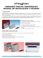
mundoclima Series MUC-CE/SE4 “Universal Fancoil ” Guía de instalación
- Tipo
- Guía de instalación

UNIDADES FANCOIL UNIVERSALES
MANUAL DE INSTALACIÓN Y USUARIO
1. INSTALACIÓN:
El lugar de instalación será determinado por el diseñador de la instalación, por un técnico de servicio o bien por parte de una persona
debidamente cualificada considerando en todo momento los requisitos técnicos así como las disposiciones y regulaciones técnicas en
vigor. La unidad fancoil deberá ser instalada por parte de una empresa autorizada según las disposiciones y regulaciones en vigor del país
donde se realice la instalación.
Las unidades fancoil están concebidas para su instalación expuesta. Todos los modelos han sido diseñados para el montaje
sobre suelo, o bien en pared o en suspensión del techo. La instalación debe permitir que el aire tratado circule libremente por
toda la habitación y se deje el suficiente espacio para mantenimiento o intervenciones de servicio.
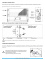
PARA MONTAJE EN TECHO:
1). Retire el filtro y afloje los tornillos (4 tornillos en la parte superior y 2 tornillos en la parte inferior).
2). Eleve y retire la cubierta.
3). Instale la unidad en el techo.
4). Disponga la conexión del tubo de agua.
5). Disponga la conexión eléctrica según el correspondiente diagrama.
6). Vuelva a instalar la cubierta y el filtro.
MANUAL DE INSTALACIÓN Y USUARIO
PARA MONTAJE EN SUELO O PARED:
1).Retire el filtro y afloje los tornillos (4 tornillos en la superior y 2
tornillos en la parte inferior).
2). Eleve y retire la cubierta.
3). Instale la unidad en la pared o en el suelo.
4). Disponga la conexión del tubo de agua.
5). Disponga la conexión eléctrica según el correspondiente
diagrama.
6). Vuelva a instalar la cubierta y el filtro.

2. CONEXIÓN HIDRÁULICA:
TLas unidades fancoil han sido concebidas y fabricadas para su instalación en sistemas de calefacción y aire acondicionado.
A continuación se detallan las características de la conexión hidráulica:
La posición de las conexiones hidráulicas puede invertirse de izquierda a derecha durante la instalación.
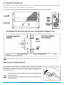
DIAGRAMA DE INSTALACIÓN DE LAS CONEXIONES HIDRÁULICAS:
Disponga las conexiones apretando las conexiones de la unidad fancoil según el sistema de par de apriete.
DRENAJE DE CONDENSADOS:
Para su aplicación en sistemas de aire acondicionado, las unidades fancoil están equipadas con una bandeja colectora de
condensados a la que se conecta la manguera de drenaje. Esta manguera debe
estar dirigida a un desagüe adecuado. Conecte una manguera de drenaje aislada
(diámetro interior ø16 mm) al terminal de la bandeja colectora y dispóngala hacia
un desagüe apropiado.
MANUAL DE INSTALACIÓN Y USUARIO
!
!
- Compruebe que el agua condensada fluye con normalidad hacia la
--bandeja colectora.
- La manguera de drenaje debería presentar una inclinación del 2%
--hacia el desagüe.

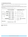
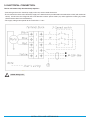
3. CONEXIONES ELÉCTRICAS:
La unidad fancoil se suministra con las conexiones eléctricas completamente dispuestas y tan solo es necesario lo
siguiente:
- Conectar a la fuente de alimentación principal y al termostato de control de la habitación.
- Las características de la fuente de alimentación principal son aptas para la corriente de entrada indicada, la cual (valores
máximos) debería ser tomada como base para los disyuntores y los cables de corriente (se deberá considerar cualquier otra
aplicación paralela).
l- La tensión de alimentación corresponde al valor nominal +/- 10%.
Cableado amarillo
MANUAL DE INSTALACIÓN Y USUARIO
!

UNIVERSAL FAN COIL UNITS
INSTALLATION AND USER MANUAL
1. INSTALLATION :
The place of installation should be established by the installation designer/services engineer or by a technically competent
person and should take into account technical requirements as well as relevant current laws and regulations. The fan coil
should be installed by a qualified company in accordance with relevant laws and regulations in force in the country of
installation.
The fan coils are designed for exposed installation. All the models are designed for floor standing or wall mounted or ceiling
suspension. Installation should allow the treated air to circulate freely throughout the room and leave sufficient space for
access for maintenance or servicing operations
FOR CEILING-MOUNTED:
1). Remove the filter and loosen the fixed screws.( 4 screws at the top and 2 screws at the bottom
2). Lift and remove the cover.
3). Install the unit to the ceiling.
4). Make water tube connection.
5). Make electrical connection as shown in the wiring diagrams.
6). Remount the cover and the filter.
INSTALLATION AND USER MANUAL
FOR FLOOR STANDING OR WALL MOUNTED:
1).Remove the filter and loosen the fixed screws.( 4 screws at
the Top and 2 screws at the bottom)
2). Lift and remove the cover.
3). Install the unit on the wall or floor.
4). Make water tube connection.
5). Make electrical connection as shown in the wiring diagrams.
6). Remount the cover and the filter.

2.WATER CONNECTION:
The fan coils have been designed and made for installation in heating and cooling air-conditioning systems.
The characteristics of the water fittings are given below:
The position of the water fittings may be reversed from left to right during installation.
INSTALLATION WATER CONNECTIONS DIAGRAM:
Fix the connections by tightening the fan coil fitting with the wrenchagainst wrench system.
CONDESATE DRAINAGE:
For use in air-conditioning systems, the fan coils are fitted with a condensate-collecting tray to which a drainpipe is connected. This pipe
should lead to a suitable drain. Connect an insulated drainage pipe (inside ø 16 mm.) to the through fitting of the tray and direct it towards a
suitable drain.
INSTALLATION AND USER MANUAL
!
!
- Check that the condensation flows out regularly into the tray.
- The drainage pipe should have a 2% slope towards the drain.
- Check all the joints for leaks.
- Apply heat-insulating material to the joints.

3. ELECTRICAL CONNECTION:
The fan coil comes fully wired and only requires :
- Connecting to the mains electricity supply and to any room control thermostat.
- The characteristics of the mains electricity supply are suitable for the input indicated in the table below, which (with maximum
--values) should serve for sizing both the circuit breakers and the power cables (any other appliances working in parallel
--should also be taken into consideration).
- The supply voltage corresponds to the rated value +/- 10%.
Yellow wiring is N.
INSTALLATION AND USER MANUAL
!
-
 1
1
-
 2
2
-
 3
3
-
 4
4
-
 5
5
-
 6
6


mundoclima Series MUC-CE/SE4 “Universal Fancoil ” Guía de instalación
- Tipo
- Guía de instalación
en otros idiomas
Artículos relacionados
-
mundoclima Series MUCSW-HG “Cassette Fancoil” Guía de instalación
-
-
-
-


