Blue Hawk 45-03202-062 Instructions Manual
- Tipo
- Instructions Manual

ITEM #0095309
42 IN. TOW LAWN SWEEPER
MODEL #45-03202-062
Questions, problems, missing parts? Before returning to your retailer, call our customer
service department at 1-877-888-8225, 8 a.m. - 8 p.m., EST, Monday - Friday.
ATTACH YOUR RECEIPT HERE
Serial Number _______________________ Purchase Date _______________________
Español p. 21
Aerosmith Rocks
FORM NO. 42572 rev. (11/02/2012)
1
Lowes.com
AB12322

2
Lowes.com
TABLE OF CONTENTS
Package Contents ............................................................................................................................3
Hardware Contents ...........................................................................................................................4
Safety Information .............................................................................................................................5
Preparation .......................................................................................................................................5
Assembly Instructions .......................................................................................................................6
Operating Instructions .....................................................................................................................15
Care and Maintenance ...................................................................................................................16
Troubleshooting ..............................................................................................................................17
Warranty .........................................................................................................................................18
Replacement Parts List ...................................................................................................................18

3
Lowes.com
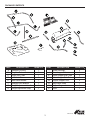
PACKAGE CONTENTS
PART DESCRIPTION QUANTITY
A Sweeper Housing 1
B Bag Arm Tube 2
C Right Hitch Tube 1
D Left Hitch Tube 1
E
Bent Hitch Bracket
1
F Straight Hitch Bracket 1
G Height Adjustment Handle 1
H Height Adjustment Strap 1
PART DESCRIPTION QUANTITY
I Brush Assembly 2
J Rear Hopper Tube 2
K Upper Hopper Side Tube 2
L Lower Hopper Side Tube 2
M Hopper Support Rod 2
N Bag Frame Strap 1
O Hopper Bag 1
P Rope 1

4
Lowes.com
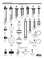
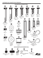
HARDWARE CONTENTS
SHOWN FULL SIZE
NOT SHOWN FULL SIZE
5/16 x 2-1/2
Bolt
Qty. 2
5/16 x 2
Bolt
Qty. 2
5/16 x 1-1/2
Bolt
Qty. 4
5/16 x 1-1/4
Bolt
Qty. 1
5/16 x 1
Bolt
Qty. 2
5/16 x 1
Bolt
Qty. 1
1/4 x 1
Bolt
Qty. 4
1/4
Nut
Qty. 4
5/16
Nut
Qty. 11
5/16
Washer
Qty. 4
Star
Washer
Qty. 1
Pivot
Bushing
Qty. 1
Spacer
Bushing
Qty. 1
Hitch
Spacer
Qty. 2
3/8 x 3
Clevis Pin
Qty. 2
1/4 x 1-3/4
Clevis Pin
Qty. 2
1/4 x 1-1/8
Clevis Pin
Qty. 2
3/8 x 1/2
Clevis Pin
Qty. 2
3/32
Hairpin Cotter
Qty. 8
1/8
Hairpin Cotter
Qty. 1
Vinyl Cap
Qty. 1
Grip
Qty. 1
Knob
Qty. 1
Hitch Pin
Qty. 1
Plastic Plug
Qty. 4

5
Lowes.com
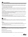
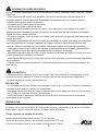
SAFETY INFORMATION
PREPARATION
Before beginning assembly of product, make sure all parts are present. Compare parts with package
contents list and hardware contents list. If any part is missing or damaged, do not attempt to
assemble the product.
Estimated Assembly Time: 60 minutes
Tools Required for Assembly (not included):
(2) 7/16 in. Open End or Box End Wrenches, (2) 1/2 in. Open End or Box End Wrenches.
WARNING
Please read and understand this entire manual before attempting to assemble, operate or install the
product.
• Read the vehicle and sweeper owner's manuals and know how to operate your vehicle and sweeper
before using this sweeper attachment. Always instruct other users before they operate the sweeper.
• Do not permit children to operate sweeper.
• Do not permit anyone to ride on sweeper.
• Never attach the hopper rope to any part of your body or clothing! Never hold onto the rope while
towing the sweeper! Attach the rope to the towing vehicle to keep it away from wheels and rotating
parts.
• Operate the sweeper at reduced speed on rough terrain, near ditches and on hillsides to prevent
loss of control.
• Vehiclebrakingandstabilitymaybeaffectedwiththeattachmentofthissweeper.Donotllthe
sweeper to maximum capacity without checking the capability of the towing vehicle to safely pull and
stop with the sweeper attached. Stay off of steep slopes.
• Stop and inspect the vehicle and sweeper for damage after striking an object. Repair any damage
before continuing operation.
• Keepthesweeperawayfromre.Excessiveheatcandamagethebrushesandhopperbagand
could cause the bag and its contents to burn.
• Before storing the sweeper, always empty the hopper bag to avoid spontaneous combustion.
• Follow maintenance and lubrication instructions as outlined in the maintenance section of this manual.
• Never attach the hopper rope to any part of your body or clothing! Never hold onto the rope while
towing the sweeper! Attach the rope to the towing vehicle to keep it away from wheels and rotating
parts.
CAUTION
• Maximum towing speed is 6 m.p.h. Driving too fast may damage wheels and bearings.
• Keepsweeperawayfromre.Excessiveheatcandamagethebrushesandhopperbagandcould
cause the bag and its contents to burn.
• Before storing the sweeper, always empty the hopper bag to avoid spontaneous combustion.

6
Lowes.com
ASSEMBLY INSTRUCTIONS
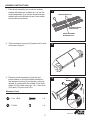
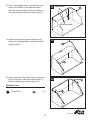
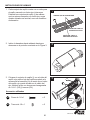
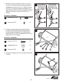
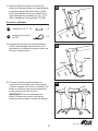
1. Each brush assembly has one brush retainer
marked with either red or black ink. Lay out the
brush assemblies (I) so that the brush retainers
marked with red and black ink are in the middle
and positioned as shown.
GG
1/4 x 1 Bolt x 2
1
2
3
2. Tip the sweeper housing (A) forward until it rests
asshowningure3.
3. Place the brush assembly (I) with the red
brush retainer on the brush shaft attached to
the sweeper housing (A) so that the red brush
retainer is positioned in the middle of the shaft.
Attach it to the shaft using two 1/4 x 1 hex bolts
(GG) and 1/4 nylock nuts (HH).
Hardware Used
RED MARK
HH
1/4 Nut x 2
OVERLAP BRISTLES
BRUSH RETAINER
MARKED BLACK
BRUSH RETAINER
MARKED RED

7
Lowes.com
X
1/4 x 1 Bolt x 2
HH
1/4 Nut x 2
4
5
6
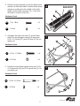
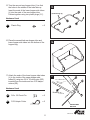
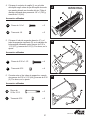
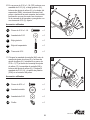
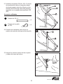
4. Place the brush assembly (I) with the black brush
retainer on the brush shaft so that the black brush
retainer is positioned in the middle of the shaft.
Attach it to the shaft using two 1/4 x 1 hex bolts
(GG) and 1/4 nylock nuts (HH).
Hardware Used
BRUSH RETAINER
MARKED BLACK
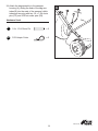
5. Assemble the right hitch tube (C) and left hitch
tube (D) to the sweeper housing (A) using four
5/16 x 1-1/2 bolts (CC) and 5/16 nuts (II). Do not
tighten yet.
Hardware Used
CC
5/16 x 1-1/2 Bolt x 4
II
5/16 Nut x 4
6. Fasten the hitch tubes together using two 5/16 x
2-1/2 hex bolts (AA) and 5/16 nylock nuts (II). Do
not tighten yet.
Hardware Used
AA
5/16 x 2-1/2 Bolt x 2
II
5/16 Nut x 2
GG

8
Lowes.com
BB
5/16 x 2 Bolt x 2
II
5/16 Nut x 2
7
8
9
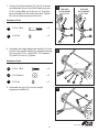
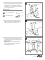
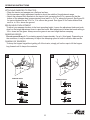
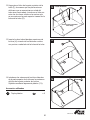
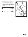
7. Arrange the hitch brackets (E) and (F) as shown
and assemble them to the hitch tubes using two
5/16 x 2 bolts (BB) and 5/16 nuts (II). The bolts
should straddle the front hitch tube bolt. Tighten
all nuts and bolts securely at this time.
Hardware Used
TRACTOR
HITCH HEIGHT
8 TO 10 IN.
TRACTOR
HITCH HEIGHT
10 TO 13 IN.
8. Assemble the height adjustment handle (G) to the
inside of the bracket attached to sweeper housing
(A) using two 5/16 x 1 bolts (EE), 5/16 washers
(JJ) and 5/16 nuts (II). Tighten.
Hardware Used
EE
5/16 x 1 Bolt x 2
II
5/16 Nut x 2
9. Assemble the grip (VV) onto the height
adjustment handle (G).
JJ
5/16 Washer x 2

9
Lowes.com
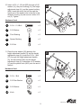
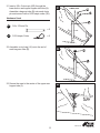
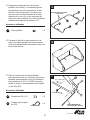
10. Insert a 5/16 x 1-1/4 bolt (DD) through a 5/16
washer (JJ), the pivot bushing (LL), the height
adjustment strap (H), and the spacer bushing
(MM). Insert the end of the bolt through the
upper part of the double hole in the end of the
sweeper housing (A) and secure it with a 5/16
nut (II). Tighten.
Hardware Used
10
11
DD
5/16 x 1-1/4 Bolt x 1
JJ
5/16 Washer x 1
LL
Pivot Bushing x 1
MM
Spacer Bushing x 1
II
5/16 Nut x 1
11. Place the star washer (KK) between the
height adjustment handle (G) and the height
adjustment strap (H). Insert the 5/16 x 1 bolt
(FF) through the height adjustment handle
(G), the star washer (KK) and the height
adjustment strap (H). Assemble a 5/16 washer
(JJ) and the plastic knob (WW) onto the end of
the bolt.
Hardware Used
FF
5/16 x 1 Bolt x 1
KK
5/16 Star Washer x 1
JJ
5/16 Washer x 1
WW
Knob x 1

10
Lowes.com
12. Turn a rear hopper tube (J) so that the brace
holes in the middle of the tube face down.
Slide the tube through the two loops sewn to
the top rear seam inside the hopper bag (O).
12
YY
Plastic Plug x 2
(holes facing down)
INNER LOOPS
13. Insert the two upper hopper side tubes (K)
throughthestitchedapsoneachsideofthe
hopper bag (O).
13
14. Insert the ends of the upper hopper side tubes
(K) into the ends of the rear hopper tube (J).
Fasten together using plastic plugs (YY).
Hardware Used
14

11
Lowes.com
15. Turn the second rear hopper tube (J) so that
the holes in the middle of the tube face up.
Insert the ends of the lower hopper side tubes
(L) into the ends of the rear hopper tube.
Fasten together using two plastic plugs (YY).
Hardware Used
15
RR
3/8 x 1/2 Clevis Pin x 2
16. Place the assembled rear hopper tube and
lower hopper side tubes into the bottom of the
hopper bag.
16
17. Attach the ends of the lower hopper side tubes
(L) to the inside of the upper hopper side
tubes (K) using two 3/8 x 1/2 clevis pins (RR)
inserted from the inside and two 3/32 hairpin
cotters (SS).
Hardware Used
17
YY
Plastic Plug x 2
HOPPER BAG
BOTTOM
SS
3/32 Hairpin Cotter x 2
(holes facing up)

12
Lowes.com
18. Insert the bag frame strap (N) into the stitched
sleeve along the front edge of the bag bottom
and attach it to the lower hopper side tubes
(L) using two 1/4 x 1-1/8 clevis pins (QQ) and
3/32 hair cotter pins (SS).
Hardware Used
18
19. Secure the bag corners around the lower
hopper side tubes (L) by snapping the bag
apstothebagbottomonbothsides.
19
20. Place the ends of the hopper support rods (M)
into the upper and lower rear hopper tubes
(J),bendingtherodsjustenoughtotintothe
holes in the tubes.
IMPORTANT: Do not over bend the rods.
Over bending will cause the steel rods to
loose supporting tension.
20
QQ
1/4 x 1-1/8 Clevis Pin x 2
SS
3/32 Hairpin Cotter x 2
SNAP
FLAP

13
Lowes.com
21. Insert a 3/8 x 3 clevis pin (OO) through the
lower hole in each upper hopper side tube (K).
Assemble a bag arm tube (B) onto each clevis
pin and secure it with a 3/32 hairpin cotter (SS).
Hardware Used
21
22. Assemble a vinyl cap (UU) onto the end of
each bag arm tube (B).
22
23. Secure the rope to the center of the upper rear
hopper tube (J).
23
OO
3/8 x 3 Clevis Pin
x 2
SS
3/32 Hairpin Cotter x 2
LOWER HOLE

14
Lowes.com
24. Attach the bag assembly to the sweeper
housing (A), sliding the ends of the bag arm
tubes (B) into the ends of the sweeper's hitch
tubes and securing with two 1/4 x 1-3/4 clevis
pins (PP) and 3/32 hair cotter pins (SS).
Hardware Used
24
PP
1/4 x 1-3/4 Clevis Pin x 2
SS
3/32 Hairpin Cotter x 2

15
Lowes.com
OPERATING INSTRUCTIONS
ATTACHING SWEEPER TO TRACTOR
• Placethetractorandsweeperonaatlevelsurface.
• Set the sweeper height adjustment handle to about the middle of its adjustment range.
• Attach the sweeper hitch brackets to the tractor hitch, arranging the 3/4 in. spacers so that the
bottomofthesweeperbagisapproximatelyleveland5in.to7in.abovetheground.Seegure25
fortractorhitchesthatare10in.to13in.abovetheground.Seegure26fortractorhitchesthat
are 8 in. to 10 in. above the ground.
BRUSH HEIGHT ADJUSTMENT
To adjust your sweeper brushes to the best operating height, loosen the adjustment knob and push
down on the height adjustment lever to raise the brush. Best adjustment is when the brush setting is
1/2 in. down into the grass. Always mow the grass to an even height before sweeping.
SWEEPING SPEED
Do not exceed 6 m.p.h. Try a starting speed of approximately 3 m.p.h. (third gear). Depending on
the conditions, it may be necessary to adjust the sweeping speed in order to achieve best results.
DUMPING OF SWEEPER
To dump the hopper bag without getting off of the tractor, simply pull on the rope to tilt the hopper
bag forward until it dumps the contents.
25
TRACTOR HITCH
10 - 13 IN.
TRACTOR HITCH
8 - 10 IN.
26

16
Lowes.com
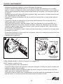
CARE AND MAINTENANCE
• Check for loose fasteners before each use.
• Clean the sweeper after each use.
a. Clean sweeper housing with a soft brush or cloth.
b. Clean debris from hopper bag with a brush or broom.
c. Remove any material which has wrapped around brushes or ends of brush shaft.
• Inspect for worn or damaged parts, such as brushes and wheels, before each use. Replace as
necessary.
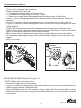
• (Figure 27) Lubricate the brush shaft bearing twice a year with a few drops of light weight oil.
• (Figure 28) Lubricate the wheel bearings each season. Remove the hub cap and apply a few drops
of light weight oil.
• (Figure 28) Every two years, remove the wheels and clean the gears found inside the wheel
housing. After cleaning, lubricate the gears with an even coat of light grease. To remove the wheel,
popoffthehubcapandremovethelocknutandatwasher.
• When storing, clean the sweeper and hopper bag thoroughly to help prevent rust and mildew.
• To collapse the hopper bag for storage, remove the two hopper support rods from the rear of the
hopper.
• Store in a dry area.
APPLY OIL HERE
27 28
HEX BOLT
FLAT WASHER
FLAT WASHER
HEX LOCK NUT
HUB CAP
SPACER
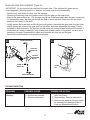
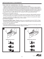
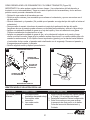
BRUSH REPLACEMENT (Figure 29 on page 17)
NOTE: Replace only one brush at a time.
• Remove the hopper bag from the sweeper.
• (Figure 29) Loosen the clamping bolt on each brush retainer. Do not loosen the center bolts which
fasten the brush retainers to the brush shaft.
• (Figure 29) Slide the brush out of the retainers, noting on which side of the brush the bristles overlap.
• (Figure 29) Install a new brush, making sure the overlap bristles are on the same side as the brush
you removed.

17
Lowes.com
29 30
GEAR AND PAWL REPLACEMENT (Figure 30)
IMPORTANT: Do not remove both wheels at the same time. (The right and left gears are not
interchangeable.) Note the position of washers and snap rings during disassembly.
• Remove only one wheel at a time from the sweeper.
• Remove the retaining rings and washers which hold the gear on the brush shaft.
• Remove the gear and drive pin. (The drive pin may fall out of the brush shaft when the gear is removed.)
• To reassemble, insert the drive pin through the hole in the brush shaft. Make sure the pin slides
back and forth easily in the shaft.
• Lightlygreasethebrushshaftandllthegearwithgrease.Assemblethegearbackontotheshaft.
• Lightly grease the axle and the gear teeth on the wheel, and then reassemble the wheel. Rotate
the wheel in both directions. The brushes should rotate only during forward rotation of the wheel. If
the brushes are driven (rotated) by both forward and reverse rotation of the wheel, the drive pin is
jamming in the gear. Disassemble to clean and lubricate the drive pin and the gear.
• Remove the second wheel and repeat the procedure.
TROUBLESHOOTING
PROBLEM POSSIBLE CAUSE CORRECTIVE ACTION
Wheels skid when
sweeping.
1. Brushes set too low.
2. Brushes are jammed.
3. Wheels are jammed.
1. Adjust height till brushes are 1/2 in.
down into grass.
2. Stop sweeper. Remove obstruction.
3. Remove one wheel at a time to check
for obstruction or damage. Refer to
Care and Maintenance section.
BRUSH ROTATION
BRUSH ROTATION
OVERLAP
BRISTLES
OVERLAP
BRISTLES
LOOSEN
CLAMPING
BOLTS
GEAR
DRIVE
PIN

18
Lowes.com
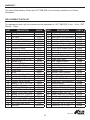
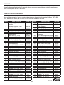
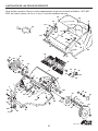
REPLACEMENT PARTS LIST
For replacement parts, call our customer service department at 1-877-888-8225, 8 a.m. - 8 p.m., EST,
Monday - Friday.
PART DESCRIPTION PART #
1 Hitch Tube, R.H. 40614
2 Hitch Tube, L.H. 40615
3 Pin, Hitch 23353
4 Tube, Hitch Spacer 23368
5 Hairpin Cotter, 1/8" #4 43343
7 Rivet, Pop C-9M5732
9 Bolt, Hex 5/16-18 x 3/4" 43182
10 Sweeper Housing 66137
11 Washer, Special 23336
12 Height Adjustment Tube 66070
13 Bolt, Hex 5/16-18 x 1" 43063
14 Bushing, Spacer 25408
15 Bolt, Hex 5/16-18 x 1-1/4" 43840
16 Washer, Star 44732
17 Washer, 5/8" SAE R19212113
18 Retainer, Dust Cover 1629-56
19 Bushing, Brush Shaft 44910
20 Brush Shaft 25850
21 Brush 48557
22 Bolt, Hex 1/4-20 x 3/4" Lg. 43012
23 Nut, Nylock 1/4-20 47189
24 Retainer, Brush (Double) 23580
25 Retainer, Brush (Single) 23581
26 Washer, 1-1/8" x .78" x .025" 44008
27 Dowel Pin (Drive) 47046
29 Nut, Nylock 5/16-18 47810
30 Spacer, .41" x 1-1/4" x .5" 44911
31 Washer, .750" x .598" x .025" 42093
32 Spacer, .78 I.D" x 1-1/4" x .5" 46219
33 Ring, Retaining .594" 1650-21
34 Washer, 1-1/8" x .594" x .025" 40001
35 Washer, 1.5" x .375" x .062" 141
36 Nut, Nylock Jam 3/8-24 1038
37 Hub Cap 2674-32
PART DESCRIPTION PART #
38 Bolt, Hex 3/8-24 x 3-1/4" 44961
39 Bushing, Pivot 23400
40 Gear, Pinion R.H. (not shown) 48652
41 Gear, Pinion L.H. 48651
42 Bolt, Hex 1/4-20 x 1" Lg. 43661
43 Ass'y, Dust Cover 64559
44 Tube, Hopper Frame (Rear) 48587
45 Tube, Upper Hopper Frame 48466
46 Tube, Lower Hopper Frame 48726
47 Plastic Plug 48402
48 Hopper Bag 48388
49 Clevis Pin, 3/8" x 1/2" 48366
50 Strap, Bag Frame 24949
51 Rod, Hopper Support 43926
52 Hopper Rope 43737
53 Cap, Vinyl 44481
54 Strap, Height Adjustment 24979
55 Bracket, Hitch 23687
56 Bracket, Hitch (Straight) 24192
57 Handle, Height Adjustment 26243
58 Tube, Bag Arm 40621
59 Pin, Clevis 3/8" x 3" 43513
60 Wheel Ass'y. (with bearings) 44985
61 Wheel Bearing 45088
62 Bolt, Hex 5/16-18 x 2-1/2" 44292
63 Bolt, Hex 5/16-18 x 2" Lg. 44180
65 Bolt, Carriage 5/16-18 x 1-1/2" 43681
66 Hairpin Cotter, 3/32" #3 43055
67 Knob, Wing 5/16-18 Thread 43720
68 Bolt, Carriage 5/16-18 x 1" 44326
69 Washer, Flat 5/16" Std. Wrt. 43081
70 Grip, Height Adjust 43943
71 Clevis Pin, 1/4" x 1-3/4" Lg. 46867
72 Clevis Pin, 1/4" x 1-1/8" 48365
WARRANTY
Two year limited warranty. Please call 1-877-888-8225 if you have any questions or for further
information.

19
Lowes.com
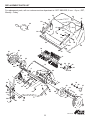
REPLACEMENT PARTS LIST
For replacement parts, call our customer service department at 1-877-888-8225, 8 a.m. - 8 p.m., EST,
Monday - Friday
1
2
10
7
20
21
22
23
24
25
26
26
27
29
29
29
30
31
32
33
35
36
37
39
41
42
43
43
55
56
60
61
60
61
63
62
3
4
5
66
71
34
9
12
29
65
15
25
52
53
66
44
45
46
44
46
48
50
51
58
58
72
49
53
45
47
59
66
59
66
66
47
16
14
13
54
67
69
69
69
39
57
68
70
A
17
18
19
38
35
11
A
B
B
D
D
C
C
29
29

20
Lowes.com
Blue Hawk & Design
®
is a registered trademark
of LF, LLC. All rights reserved.
Printed in USA

21
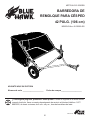
ARTÍCULO Nº 0095309
BARREDORA DE
REMOLQUE PARA CÉSPED
42 PULG. (106 cm)
MODELO Nro. 45-03202-062
¿Tiene alguna pregunta, problema o faltan piezas? Antes de regresar a la tienda donde
compró el artículo, llame a nuestro departamento de servicio al cliente al teléfono 1-877-
888-8225, de lunes a viernes, de 8 a.m. a 8 p.m., hora del meridiano del este.
ADJUNTE AQUÍ SU FACTURA
Número de serie _____________________ Fecha de compra _____________________
Aerosmith Rocks
Lowes.com

22
Lowes.com
TABLA DE CONTENIDO
Contenido del paquete ....................................................................................................................23
Contenido del paquete de accesorios ............................................................................................24
Información sobre seguridad ..........................................................................................................25
Preparación ....................................................................................................................................25
Instrucciones de armado ................................................................................................................26
Instrucciones para el funcionamiento .............................................................................................35
Cuidado y mantenimiento ...............................................................................................................36
Identicaciónysolucióndefallas ...................................................................................................37
Garantía ..........................................................................................................................................38
Lista de piezas de repuesto ............................................................................................................38

23
Lowes.com
CONTENIDO DEL PAQUETE
PIEZA DESCRIPCIÓN CANTIDAD
A Carcasa de la barredora 1
B Tubo del brazo de la bolsa 2
C Tubo de enganche
derecho
1
D Tubo de enganche
izquierdo
1
E
Ménsula de enganche en
forma de S
1
F Ménsula de enganche
recta
1
G Manija de ajuste de altura 1
H Barra de ajuste de altura 1
PIEZA DESCRIPCIÓN CANTIDAD
I Conjunto de cepillo 2
J Tubo de la parte posterior
de la tolva
2
K Tubo lateral de la parte
superior de la tolva
2
L Tubo lateral de la parte
inferior de la tolva
2
M Barra de soporte de la
tolva
2
N Varilla del marco de la
bolsa
1
O Bolsa de la tolva 1
P Cuerda 1

24
Lowes.com
CONTENIDO DEL PAQUETE DE ACCESORIOS
SE MUESTRA EN TAMAÑO REAL
NO SE MUESTRA EN TAMAÑO REAL
Perno de
5/16 x 2-1/2
Cant. 2
Perno de
5/16 x 2
Cant. 2
Perno de
5/16 x 1-1/2
Cant. 4
Perno de
5/16 x 1-1/4
Cant. 1
Perno de
5/16 x 1
Cant. 2
Perno de
5/16 x 1
Cant. 1
Perno de
1/4 x 1
Cant. 4
Tuerca de
1/4
Cant. 4
Tuerca de
5/16
Cant. 11
Arandela de
5/16
Cant. 4
Arandela
estrella
Cant. 1
Buje
giratorio
Cant. 1
Buje del
espaciador
Cant. 1
Espaciador
del enganche
Cant. 2
Pasador de
3/8 x 3
Cant. 2
Pasador de
1/4 x 1-3/4
Cant. 2
Pasador de
1/4 x 1-1/8
Cant. 2
Pasador de
3/8 x 1/2
Cant. 2
Pasador de
horquilla de 3/32
Cant. 8
Pasador de
horquilla de 1/8
Cant. 1
Cubierta de vinilo
Cant. 1
Mango
Cant. 1
Perilla
Cant. 1
Pasador de enganche
Cant. 1
Tapón plástico
Cant. 4

25
Lowes.com
INFORMACIÓN SOBRE SEGURIDAD
PREPARACIÓN
Antes de comenzar con el armado del producto, asegúrese de contar con todas las piezas. Compare
laspiezasconlalistadondeguraelcontenidodelpaqueteydelpaquetedeaccesorios.Sifaltara
alguna pieza o alguna estuviera dañada, no intente armar el producto.
Tiempo estimado de armado: 60 minutos
Herramientas necesarias para el armado (no se incluyen):
(2) Llaves de extremo abierto o de extremo a trinquete de 7/16 pulg.
(2) Llaves de extremo abierto o de extremo a trinquete de 1/2 pulg.
ADVERTENCIA
Por favor, lea para comprender todo el manual antes de intentar ensamblar, hacer funcionar o instalar
el producto.
• Lea los manuales del usuario de la barredora y del vehículo de remolque y familiarícese con su
operación antes de usar este accesorio de barredora. Siempre instruya a otros usuarios sobre su
operación, antes de que operen su barredora.
• No permita que los niños operen la barredora.
• No permita que nadie monte la barredora.
• ¡Nunca amarre la cuerda de la tolva a su cuerpo o a su ropa! ¡Nunca se sostenga de la cuerda
mientras remolca la barredora! Amarre la cuerda al vehículo de remolque para mantener la barredora
alejada de ruedas y partes giratorias.
• En terreno quebrado, cerca de zanjas o en colinas, opere la barredora a baja velocidad para prevenir la
pérdida de control.
• El frenado y la estabilidad del vehículo pueden verse afectados al acoplar el accesorio de la barredora.
Nollenelabarredoraasumáximacapacidaddecargasinvericarlacapacidaddelvehículopara
remolcar y detener la barredora en forma segura. Manténgase alejado de las grandes pendientes.
• Deténgase e inspeccione el vehículo de remolque y la barredora después de haber golpeado algún
objeto. Repare cualquier daño que haya causado antes de continuar la operación.
• Mantenga la barredora lejos del fuego. El calor excesivo puede dañar los cepillos y la bolsa de la tolva
y hacer que se queme la bolsa y su contenido.
• Antes de guardar la barredora, siempre vacíe la bolsa de la tolva para evitar la combustión espontánea
de su contenido.
• Siga las instrucciones de mantenimiento y lubricación descriptas en la sección de mantenimiento de
este manual.
• ¡Nunca amarre la cuerda de la tolva a su cuerpo o a su ropa! ¡Nunca se sostenga de la cuerda
mientras remolca la barredora! Amarre la cuerda al vehículo de remolque para mantener la
barredora alejada de ruedas y partes giratorias.
PRECAUCIÓN
• La velocidad máxima de remolque recomendada es de 6 m.p.h. (10 km/h). Conducir a demasiada
velocidad puede dañar las ruedas y los rodamientos.
• Mantenga la barredora lejos del fuego. El calor excesivo puede dañar los cepillos y la bolsa de la
tolva y hacer que se queme la bolsa y su contenido.
• Antes de guardar la barredora, siempre vacíe la bolsa de la tolva para evitar la combustión
espontánea de su contenido.

26
Lowes.com
INSTRUCCIONES DE ARMADO
1. Cada conjunto de cepillo cuenta con un retén para
el cepillo marcado con tinta roja o tinta negra.
Extienda los conjuntos de cepillo (I) de manera
que los retenes marcados con tinta roja y negra
queden ubicados en la mitad, como se muestra a
continuación.
GG
Perno de 1/4 x 1 x 2
1
2
3
2. Incline la barredora hacia adelante hasta que
descanse en la posición mostrada en la Figura 3.
3. Coloque el conjunto de cepillo (I) con el retén del
cepillo rojo sobre el eje del cepillo acoplado a la
carcasa de la barredora (A) de modo que el retén
del cepillo rojo quede ubicado en el medio del
eje. Acóplelo al eje con dos pernos hexagonales
de 1/4 x 1 (GG) y tuercas (HH).
Accesorios utilizados
MARCA
ROJA
HH
Tuerca de 1/4 x 1 x 2
CERDAS QUE SE SUPERPONEN
RETÉN DEL CEPILLO
MARCADO EN NEGRO
RETÉN DEL CEPILLO
MARCADO EN ROJO

27
Lowes.com
X
Perno de 1/4 x 1 x 2
HH
Tuerca de 1/4 x 2
4
5
6
4. Coloque el conjunto de cepillo (I) con el retén
del cepillo negro sobre el eje del cepillo de modo
que quede ubicado en el medio del eje. Fíjelo al
vástago utilizando dos pernos de 1/4 x 1 (GG) y
tuercas de 1/4 (HH).
Accesorios utilizados
RETÉN DEL CEPILLO
MARCADO EN NEGRO
5. Coloque el tubo de enganche derecho (C) y el
tubo de enganche izquierdo (D) en la carcasa de
la barredora utilizando cuatro pernos de 5/16 x
1-1/2 (CC) y tuercas de 5/16 (II). Por ahora, no lo
ajuste.
Accesorios utilizados
CC
Perno de 5/16 x 1-1/2 x 4
II
Tuerca de 5/16 x 4
6. Conecte entre sí los tubos de enganche, usando
dos pernos de 5/16 x 2-1/2 (AA) y tuercas de 5/16
(II). Por ahora, no lo ajuste.
Accesorios utilizados
AA
Perno de
5/16 x 2-1/2
x 2
II
Tuerca de 5/16 x 2
GG

28
Lowes.com
BB
Perno de 5/16 x 2 x 2
II
Tuerca de 5/16 x 2
7
8
9
7. Monte los brazos de enganche (E) y (F) como
se ilustra y conéctelos a los tubos de enganche
utilizando dos pernos de 5/16 x 2 (BB) y tuercas
de 5/16 (II). Los pernos deben montarse uno a
cada lado del perno del tubo de enganche. Ajuste
todas las tuercas y los pernos, ahora si con
rmeza.
Accesorios utilizados
LA ALTURA DEL
ENGANCHE DEL
TRACTOR ES DE 8 A
10 PULG. (20 A 25 CM)
LA ALTURA DEL
ENGANCHE DEL
TRACTOR ES DE
10 A 13 PULG. (25
A 33 CM)
8. Coloque la manija de ajuste de altura (G) en
el interior de la ménsula que está sujetada a
la carcasa de la barredora (A), utilizando dos
pernos de 5/16 x 1 (EE), arandelas de 5/16 (JJ) y
tuercas de 5/16 (II). Ajuste.
Accesorios utilizados
EE
Perno de 5/16 x 1 x 2
II
Tuerca de 5/16 x 2
9. Coloque el mango (VV) en la manija de ajuste de
la altura.
JJ
Arandela de 5/16 x 2

29
Lowes.com
10. En un perno de 5/16 x 1-1/4 (DD) coloque una
arandela de 5/16 (JJ), el buje giratorio (LL),
la barra de ajuste de altura (H) y los bujes del
espaciador (MM). Introduzca el extremo del
perno a través de la parte superior de la doble
perforación que se encuentra en el extremo
de la carcasa de la barredora y asegúrelo con
una tuerca de 5/16 (II). Ajuste.
Accesorios utilizados
10
11
DD
Perno de 5/16 x 1-1/4 x 1
JJ
Arandela de 5/16 x 1
LL
Buje giratorio x 1
MM
Buje del espaciador x 1
II
Tuerca de 5/16 x 1
11. Coloque la arandela de estrella (KK) entre la
manija de ajuste de altura (G) y la barra de
ajuste de altura (H). Introduzca un perno de
5/16 x 1 (FF) a través de la manija de ajuste
de altura (G), la arandela de estrella (KK) y
la barra de ajuste de altura (H). Coloque la
arandela de 5/16 (JJ) y la perilla de plástico
(WW) en el extremo del perno.
Accesorios utilizados
FF
Perno de 5/16 x 1 x 1
KK
Arandela estrella x 1
JJ
Arandela de 5/16 x 1
WW
Perilla x 1

30
Lowes.com
12. Haga girar el tubo de la parte posterior de la
tolva (J), de manera que las perforaciones
del brazo que se encuentran en mitad del
tubo miren hacia abajo. Introduzca el tubo por
entre los dos lazos cosidos a la costura que
se encuentra en la parte superior trasera de la
bolsa de la tolva (O).
12
YY
Tapón plástico x 2
perforaciones orientadas
hacia abajo
LAZOS INTERNOS
13. Inserte los dos tubos laterales superiores de
la tolva (K) a través de los faldones cosidos
con puntos a cada lado de la bolsa de la tolva.
13
14. Introduzca los extremos de los tubos laterales
de la parte superior de la tolva en los extremos
del tubo de la parte posterior de la tolva.
Sujételos mediante tapones de plástico (YY).
Accesorios utilizados
14

31
Lowes.com
15. Haga girar el segundo tubo de la parte
posterior de la tolva (J), de manera que las
perforaciones que se encuentran en mitad
del tubo miren hacia arriba. Introduzca los
extremos de los tubos laterales de la parte
superior de la tolva (L) en los extremos del
tubo de la parte posterior de la tolva. Sujételos
mediante dos tapones de plástico (YY).
Accesorios utilizados
15
RR
Pasador de 3/8 x 1/2 x 2
16. Coloque el tubo de la parte posterior de la
tolva y los tubos laterales de la parte inferior
de la tolva ensamblados en la parte inferior de
la bolsa de la tolva.
16
17. Fije los extremos de los tubos laterales
inferiores de la tolva (L) al interior de los tubos
laterales superiores de la tolva (K) utilizando
dos pasadores de 3/8 x 1/2 (RR) insertados
desde el interior y dos pasadores de horquilla
(J) de 3/32 (SS).
Accesorios utilizados
17
YY
Tapón plástico x 2
PARTE INFERIOR DE
LA BOLSA DE LA TOLVA
SS
Pasador de horquilla
de 3/32
x 2
perforaciones orientadas
hacia arriba

32
Lowes.com
18. Inserte la barra del marco de la bolsa (N)
dentro de la manga cosida, a lo largo del borde
frontal de la parte inferior de la bolsa y fíjela
a los tubos laterales de la parte inferior de la
tolva utilizando dos pasadores de 1/4 x 1-1/8
(QQ) y pasadores de horquilla de 3/32 (SS).
Accesorios utilizados
18
19. Asegure las esquinas de la bolsa alrededor
de los tubos laterales inferiores de la tolva,
abrochando los faldones a la parte inferior de
la bolsa, a ambos lados.
19
20. Coloque los extremos de las barras de
soporte de la tolva (M) en los tubos superior
e inferior traseros de la tolva (J), doblando las
barraslosucienteparaqueseintroduzcan
en las perforaciones de los tubos.
IMPORTANTE: No curve demasiado las
barras. Doblarlas en exceso hará que las
barras de acero pierdan su tensión de soporte.
20
QQ
Pasador de 1/4 x 1-1/8 x 2
SS
Pasador de horquilla
de 3/32
x 2
FALDÓN
PRESIÓN

33
Lowes.com
21. Introduzca el pasador (OO) de 3/8 x 3 a través
de la perforación inferior de cada tubo lateral
de la parte superior de la tolva. Monte un tubo
del brazo de la bolsa (B) sobre cada pasador y
asegúrelo con un pasador de horquilla de 3/32
(SS).
Accesorios utilizados
21
22. Coloque una cubierta de vinilo (UU) en el
extremo de cada tubo del brazo de la bolsa (B).
22
23. Asegure la cuerda al centro del tubo superior
y trasero del marco de la tolva.
23
OO
Pasador de 3/8 x 3
x 2
SS
Pasador de horquilla
de 3/32
x 2
PERFORACIÓN
INFERIOR

34
Lowes.com
24. Fije la bolsa de la tolva a la carcasa de la
barredora (A), deslizando los extremos de
los tubos del brazo de la bolsa dentro de los
extremos de los tubos de enganche de la
barredora y asegúrelos con dos pasadores de
1/4 x 1-3/4 (PP) y pasadores de horquilla de
3/32 (SS).
Accesorios utilizados
24
PP
Pasador de 1/4 x 1-3/4
x 2
SS
Pasador de horquilla
de 3/32
x 2

35
Lowes.com
INSTRUCCIONES PARA EL FUNCIONAMIENTO
CÓMO CONECTAR LA BARREDORA AL TRACTOR
• Coloqueeltractorylabarredorasobreunasupercieplanaynivelada.
• Gradúe la manija de ajuste de altura de la barredora alrededor de la mitad de su rango de ajuste.
• Fije los brazos de enganche de la barredora al enganche del tractor, colocando los espaciadores
de 3/4 pulg. de manera que la base de la bolsa de la barredora quede a una altura de 5 a 7 pulg. (13
a 18 cm). Vea en la Figura 25 la forma en que quedan los enganches del tractor cuando están entre
10 a 13 pulg. (25 a 33 cm) por encima del suelo. Vea en la Figura 26 la forma en que quedan los
enganches del tractor cuando están entre 8 a 10 pulg. (20 a 25 cm) por encima del suelo.
AJUSTE DE LA ALTURA DEL CEPILLO
Paraajustarloscepillosdesubarredoraalamejoralturadeoperación,aojelaperilladeajustey
presione hacia abajo sobre la palanca de ajuste de altura para levantar el cepillo. El mejor ajuste
escuandolagraduacióndelcepilloestá1/2pulg.(1,2cm)pordebajodelasuperciedelcésped.
Siempre corte el césped a una altura pareja, antes de barrer.
VELOCIDAD DE BARRIDO
No supere las 6 M.P.H. (aprox. 10 km/h). Intente con una velocidad de inicio de 3 M.P.H. (5 kph)
(en tercera). Dependiendo de las condiciones, puede ser necesario ajustar la velocidad de barrido,
andeobtenerlosmejoresresultados.
VACIADO DE LA BARREDORA
Para vaciar la bolsa de la tolva sin tener que bajarse del tractor, sólo jale de la cuerda para inclinar
la bolsa de la tolva hacia adelante hasta que vuelque el contenido.
25
ENGANCHE DEL TRACTOR
10 - 13 pulg.
(25 a 33 cm)
ENGANCHE DEL TRACTOR
8 - 10 pulg.
(20 a 25 cm)
26

36
Lowes.com
CUIDADO Y MANTENIMIENTO
• Veriquelapresenciadepernosytuercasojosantesdecadauso.
• Limpie la barredora después de cada uso. a) Limpie la carcasa de la barredora con un cepillo
suave o un paño. b) Limpie los residuos de la bolsa de la tolva con una escoba o con un cepillo. c)
Retire cualquier material que haya quedado enganchado en los cepillos o en los extremos del eje
del cepillo.
• Veriquelapresenciadepiezasdañadasogastadas,talescomocepillosyruedas,antesdecada
uso. Reemplácelos si fuera necesario.
• (Figura 27) Lubrique el rodamiento del eje del cepillo dos veces al año con unas pocas gotas de
aceite liviano.
• (Figura 28) Lubrique los rodamientos de las ruedas cada temporada. Quite la tapa del cubo y
aplique unas gotas de aceite liviano.
• (Figura 28) Cada dos años, retire las ruedas y limpie los rodamientos que se encuentran en el
interior del alojamiento de la rueda. Después de limpiar, lubrique los rodamientos con una capa
uniforme de grasa liviana. Para retirar la rueda, quite a presión la tapa del cubo y retire la tuerca
de seguridad y la arandela plana.
• En el momento de guardar el equipo, limpie muy bien la barredora y la bolsa de la tolva para evitar
la oxidación y el moho.
• Para doblar la bolsa de la tolva cuando se va a guardar, retire las dos barras de soporte de la tolva
de la parte trasera de la misma.
• Guárdela en un lugar seco.
APLIQUE
ACEITE
AQUÍ
27 28
PERNO HEXAGONAL
ARANDELA PLANA
ARANDELA PLANA
TUERCA HEXAGONAL
DE SEGURIDAD
TAPA DEL
CUBO
ESPACIADOR
CÓMO REEMPLAZAR EL CEPILLO (Figura 29 en la página 17)
NOTA: Cambie un cepillo por vez.
• Retire la bolsa de la tolva de la barredora.
• (Figura29)Aojeelpernodesujeciónencadareténdelcepillo.Noaojelospernoscentralesque
sujetan los retenes al eje del cepillo.
• (Figura 29) Retire el cepillo deslizándolo entre los retenes, tenga en cuentas cuál es el lado del
cepillo en el que se superponen las cerdas.
• (Figura 29) Instale el cepillo nuevo, asegurándose de que las cerdas se superpongan en el mismo
lado del cepillo, en la misma posición que estaban antes de haberlo retirado.

37
Lowes.com
29 30
CÓMO REEMPLAZAR LOS RODAMIENTOS Y EL DOBLE TRINQUETE (Figura 30)
IMPORTANTE: No retire ambas ruedas al mismo tiempo. (Los rodamientos del lado derecho e
izquierdo no son intercambiables.) Tenga en cuenta la posición de las arandelas y de los anillos a
presión cuando proceda a desarmar la rueda.
• Retire sólo una rueda de la barredora por vez.
• Quite los anillos retenes y las arandelas que sostienen el rodamiento y que se encuentran en el
eje del cepillo.
• Quite el rodamiento y el pasador. (Es posible que el pasador se caiga del eje del cepillo al retirar el
rodamiento.)
• Para proceder al armado, introduzca el pasador a través de la perforación del eje del cepillo.
Asegúrese de que el pasador pueda moverse con facilidad hacia adelante y atrás a lo largo del eje.
• Aplique una pequeña cantidad de grasa en el eje del cepillo y llene el rodamiento con grasa.
Coloque nuevamente el rodamiento en el eje.
• Aplique una pequeña cantidad de grasa al eje y a los dientes del cojinete en la rueda y luego
vuelva a colocar la rueda. Haga girar la rueda en ambas direcciones. Los cepillos deben girar sólo
cuando la rueda avanza. Si los cepillos fueran impulsados (girados) por la marcha hacia adelante
yhaciaatrásdelasruedas,elpasadorestáinterriendoconelengranaje.Desarmeelpasadory
el engranaje para limpiarlo y lubricarlo.
• Quite la segunda rueda y repita el procedimiento.
IDENTIFICACIÓN Y SOLUCIÓN DE FALLAS
PROBLEMA POSIBLE CAUSA ACCIÓN CORRECTIVA
Las ruedas patinan
al barrer.
1. Los cepillos están
graduados demasiado abajo.
2. Los cepillos están
atascados.
3. Las ruedas están
atascadas.
1. Ajuste la altura hasta que los cepillos queden
a 1/2 pulg. (1,2 cm) dentro del césped.
2. Detenga la barredora. Elimine la obstrucción.
3. Quiteunaruedaporvezparavericar
la presencia de obstrucción o de daños.
Consulte la sección Mantenimiento y
Cuidado.
ROTACIÓN DEL CEPILLO
ROTACIÓN DEL CEPILLO
CERDAS QUE
SE SUPERPONEN
CERDAS QUE
SE SUPERPONEN
AFLOJE LOS
PERNOS DE
SUJECIÓN
ENGRANAJE
PASADOR

38
Lowes.com
LISTA DE PIEZAS DE REPUESTO
Para solicitar repuestos, llame a nuestro departamento de servicio al cliente al teléfono 1-877-888-
8225, de lunes a viernes, de 8 a.m. a 8 p.m., hora del meridiano del este.
PIEZA DESCRIPCIÓN PIEZA #
1 Tubo de enganche, lado
derecho
40614
2 Tubo de enganche, lado
izquierdo
40615
3 Pasador de enganche 23353
4 Tubo, espaciador del enganche 23368
5 Pasador de horquilla de 1/8" 43343
7 Remache, pop C-9M5732
9 Perno de 5/16” x 3/4" 43182
10 Carcasa de la barredora 66137
11 Arandela, especial 23336
12 Tubo de ajuste de altura 66070
13 Perno de 5/16”-18 x 1" 43063
14 Buje, espaciador 25408
15 Perno de 5/16-18” x -1-1/4" 43840
16 Arandela, estrella 44732
17 Arandela SAE de 5/8" R19212113
18 Retén, tapa para el polvo 1629-56
19 Buje, eje del cepillo 44910
20 Eje del cepillo 25850
21 Cepillo 48557
22 Perno de 1/4-20 x 3/4" 43012
23 Tuerca de 1/4-20" 47189
24 Retén, cepillo (doble) 23580
25 Retén, cepillo (simple) 23581
26 Arandela, 1-1/8" x .78" x 0.025" 44008
27 Pasador de espiga (rotación) 47046
29 Tuerca de 5/16-18" 47810
30 Espaciador, 0.41" x 1-1/4" x 0.5" 44911
31 Arandela, 3/4" x .598" x .025" 42093
32 Espaciador, .78" x 1-1/4" x 0.5" 46219
33 Anillo, retén de 0.594" 1650-21
34 Arandela, 1-1/8" x .594" x .025" 40001
35 Arandela, 1,5" x .375" x .062" 141
36 Tuerca de 3/8-24" 1038
37 Tapa de cubo 2674-32
38 Perno de 3/8-24” x 3-1/4" 44961
PIEZA DESCRIPCIÓN PIEZA #
39 Buje, pivote 23400
40 Engranaje, piñón, lado derecho
(no se muestra)
48652
41 Engranaje, piñón lado izquierdo 48651
42 Perno de 1/4-20 x 1" 43661
43 Conjunto, tapa para el polvo 64559
44 Tubo, marco de la tolva
(delantero)
48587
45 Tubo, marco superior de la tolva 48466
46 Tubo, marco inferior de la tolva 48726
47 Tapón de plástico 48402
48 Bolsa de la tolva 48388
49 Pasador, 3/8" x 1/2" 48366
50 Barra, marco de la bolsa 24949
51 Barra, soporte de la tolva 43926
52 Cuerda de la tolva 43737
53 Cubierta, vinilo 44481
54 Barra, ajuste de altura 24979
55 Brazo, enganche 23687
56 Brazo, enganche (recto) 24192
57 Manija, ajuste de altura 26243
58 Tubo, brazo de la bolsa 40621
59 Pasador, de 3/8" x 3" 43513
60 Rueda (con rodamientos) 44985
61 Rodamiento de la rueda 45088
62 Perno de 5/16-18” x 2-1/2" 44292
63 Perno de 5/16-18 x 2" 44180
65 Perno de 5/16-18 x 1-1/2" 43681
66 Pasador de horquilla de 3/32" 43055
67 Perilla, mariposa 43720
68 Perno de 5/16-18 x 1" 44326
69 Arandela, plana de 5/16" 43081
70 Mango, ajuste de la altura 43943
71 Pasador, 1/4" x 1-3/4" 46867
72 Pasador, 1/4" x 1-1/8" 48365
GARANTÍA
Dos años de garantía limitada. En caso de alguna pregunta o para obtener más información, por
favor comuníquese al 1-877-888-8225.

39
Lowes.com
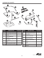
ILUSTRACIÓN DE LAS PIEZAS DE REPUESTO
Para solicitar repuestos, llame a nuestro departamento de servicio al cliente al teléfono 1-877-888-
8225, de lunes a viernes, de 8 a.m. a 8 p.m., hora del meridiano del este.
1
2
10
7
20
21
22
23
24
25
26
26
27
29
29
29
30
31
32
33
35
36
37
39
41
42
43
43
55
56
60
61
60
61
63
62
3
4
5
66
71
34
9
12
29
65
15
25
52
53
66
44
45
46
44
46
48
50
51
58
58
72
49
53
45
47
59
66
59
66
66
47
16
14
13
54
67
69
69
69
39
57
68
70
A
17
18
19
38
35
11
A
B
B
D
D
C
C
29
29

40
Lowes.com
Blue Hawk & Design® es una marca registrada
de LF, LLC. Todos los derechos reservados.
Impreso en EE.UU.
-
 1
1
-
 2
2
-
 3
3
-
 4
4
-
 5
5
-
 6
6
-
 7
7
-
 8
8
-
 9
9
-
 10
10
-
 11
11
-
 12
12
-
 13
13
-
 14
14
-
 15
15
-
 16
16
-
 17
17
-
 18
18
-
 19
19
-
 20
20
-
 21
21
-
 22
22
-
 23
23
-
 24
24
-
 25
25
-
 26
26
-
 27
27
-
 28
28
-
 29
29
-
 30
30
-
 31
31
-
 32
32
-
 33
33
-
 34
34
-
 35
35
-
 36
36
-
 37
37
-
 38
38
-
 39
39
-
 40
40


Blue Hawk 45-03202-062 Instructions Manual
- Tipo
- Instructions Manual
En otros idiomas
- English: Blue Hawk 45-03202-062
Otros documentos
-
Agri-Fab 45-0331 Manual de usuario
-
-
-
-
-
-
-
-
-
AllFitHD AF-5026LS Manual de usuario