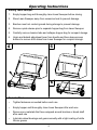
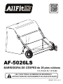
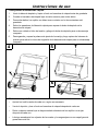
El AllFitHD AF-5026LS es un equipo que te permite barrer tu césped de manera eficiente. Cuenta con la capacidad de barrer una superficie de hasta 26 pies cúbicos, lo cual lo hace ideal para jardines de tamaño mediano a grande. El AF-5026LS tiene una altura de barrido ajustable, lo que te permite adaptarlo a las diferentes condiciones del césped. Además, cuenta con un sistema de descarga rápida que te permite vaciar el contenedor de recolección de forma sencilla y rápida.
El AllFitHD AF-5026LS es un equipo que te permite barrer tu césped de manera eficiente. Cuenta con la capacidad de barrer una superficie de hasta 26 pies cúbicos, lo cual lo hace ideal para jardines de tamaño mediano a grande. El AF-5026LS tiene una altura de barrido ajustable, lo que te permite adaptarlo a las diferentes condiciones del césped. Además, cuenta con un sistema de descarga rápida que te permite vaciar el contenedor de recolección de forma sencilla y rápida.


-
 1
1
-
 2
2
-
 3
3
-
 4
4
-
 5
5
-
 6
6
-
 7
7
-
 8
8
-
 9
9
-
 10
10
-
 11
11
-
 12
12
-
 13
13
-
 14
14
-
 15
15
-
 16
16
-
 17
17
-
 18
18
-
 19
19
-
 20
20
-
 21
21
-
 22
22
-
 23
23
-
 24
24
-
 25
25
-
 26
26
-
 27
27
-
 28
28
-
 29
29
-
 30
30
-
 31
31
-
 32
32


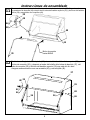
El AllFitHD AF-5026LS es un equipo que te permite barrer tu césped de manera eficiente. Cuenta con la capacidad de barrer una superficie de hasta 26 pies cúbicos, lo cual lo hace ideal para jardines de tamaño mediano a grande. El AF-5026LS tiene una altura de barrido ajustable, lo que te permite adaptarlo a las diferentes condiciones del césped. Además, cuenta con un sistema de descarga rápida que te permite vaciar el contenedor de recolección de forma sencilla y rápida.
en otros idiomas
- English: AllFitHD AF-5026LS User manual
Otros documentos
-
 Blue Hawk 45-03202-062 Instructions Manual
-
Agri-Fab 45-0546 Manual de usuario
-
-
-
-
-
-
-
