Cameo CLMP10WRGB Manual de usuario
- Categoría
- Focos
- Tipo
- Manual de usuario
Este manual también es adecuado para

MATRIX 300 RGB
LED MATRIX PANEL 5X5 10W RGB
CLMP10WRGB
USER´S MANUAL
BEDIENUNGSANLEITUNG
MANUEL D`UTILISATION
MANUAL DE USUARIO
INSTRUKCJA OBSŁUGI
MANUALE D‘ USO

CONTENTS / INHALTSVERZEICHNIS / CONTENU / CONTENIDO / TREŚĆ / CONTENUTO
ENGLISH
PREVENTIVE MEASURES 3-4
INTRODUCTION 4
CONNECTIONS, OPERATING AND DISPLAY ELEMENTS 5-6
OPERATION 6-8
MOUNTING 9
DMX TECHNOLOGY 10
TECHNICAL DATA 11
MANUFACTURER’S DECLARATIONS 11-12
DMX CONTROL 63-75
DEUTSCH
SICHERHEITSHINWEISE 13-14
EINFÜHRUNG 14
ANSCHLÜSSE, BEDIEN- UND ANZEIGEELEMENTE 15-16
BEDIENUNG 16-18
MONTAGE 19
DMX TECHNIK 20
TECHNISCHE DATEN 21
HERSTELLERERKLÄRUNGEN 21-22
DMX STEUERUNG 63-75
FRANCAIS
MESURES PRÉVENTIVES 23-24
INTRODUCTION 24
RACCORDEMENTS, ÉLÉMENTS DE COMMANDE ET
D’AFFICHAGE 25-26
MODE D’UTILISATION 26-28
MONTAGE 29
TECHNOLOGIE DMX 30
CARACTÉRISTIQUES TECHNIQUES 31
DÉCLARATIONS DU FABRICANT 31-32
PILOTAGE EN MODE DMX 63-75
ESPAÑOL
MEDIDAS DE SEGURIDAD 33-34
INTRODUCCIÓN 34
CONEXIONES, ELEMENTOS DE MANEJO Y ELEMENTOS DE
VISUALIZACIÓN 35-36
FUNCIONAMIENTO 36-38
MONTAJE 39
TECNOLOGÍA DMX 40
DATOS TÉCNICOS 41
DECLARACIONES DEL FABRICANTE 41-42
CONTROL DMX 63-75
POLSKI
ŚRODKI OSTROŻNOŚCI 43-44
WPROWADZENIE 44
GNIAZDA, PANEL OBSŁUGI I WSKAŹNIKI 45-46
OBSŁUGA 46-48
MONTAŻ 49
TECHNIKA DMX 50
DANE TECHNICZNE 51
OŚWIADCZENIA PRODUCENTA 51-52
STEROWANIE DMX 63-75
ITALIANO
MISURE PRECAUZIONALI 53-54
INTRODUZIONE 54
CONNESSIONI, ELEMENTI DI COMANDO E VISUALIZZAZIONE 55-56
UTILIZZO 56-58
MONTAGGIO 59
TECNOLOGIA DMX 60
DATI TECNICI 61
DICHIARAZIONI DEL PRODUTTORE 61-62
CONTROLLO DMX 63-75

3
DMX
DEUTSCHFRANCAIS
ESPAÑOL
ENGLISH
ITALIANO POLSKI
ENGLISH
YOU‘VE MADE THE RIGHT CHOICE!
We have designed this product to operate reliably over many years. Please read this User‘s Manual carefully, so that you can begin making
optimum use of your Cameo Light product quickly. Learn more about Cameo Light on our website WWW.CAMEOLIGHT.COM.
PREVENTIVE MEASURES
1. Please read these instructions carefully.
2. Keep all information and instructions in a safe place.
3. Follow the instructions.
4. Observe all safety warnings. Never remove safety warnings or other information from the equipment.
5. Use the equipment only in the intended manner and for the intended purpose.
6. Use only sufficiently stable and compatible stands and/or mounts (for fixed installations). Make certain that wall mounts are properly installed and
secured. Make certain that the equipment is installed securely and cannot fall down.
7. During installation, observ e the applicable safety regulations for your country.
8. Never install and operate the equipment near radiators, heat registers, ovens or other sources of heat. Make certain that the equipment is
always installed so that is cooled sufficiently and cannot overheat.
9. Never place sources of ignition, e.g., burning candles, on the equipment.
10. Ventilation slits must not be blocked.
11. This appliance is designed exclusively for indoor use, do not use this equipment in the immediate vicinity of water (does not apply
to special outdoor equipment - in this case, observe the special instructions noted below). Do not expose this equipment to flammable
materials, fluids or gases.
12. Make certain that dripping or splashed water cannot enter the equipment. Do not place containers filled with liquids, such as vases or
drinking vessels, on the equipment.
13. Make certain that objects cannot fall into the device.
14. Use this equipment only with the accessories recommended and intended by the manufacturer.
15. Do not open or modify this equipment.
16. After connecting the equipment, check all cables in order to prevent damage or accidents, e.g., due to tripping hazards.
17. During transport, make certain that the equipment cannot fall down and possibly cause property damage and personal injuries.
18. If your equipment is no longer functioning properly, if fluids or objects have gotten inside the equipment or if it has been damaged in
anot her way, switch it off immediately and unplug it from the mains outlet (if it is a powered device). This equipment may only be repaired
by authorized, qualified personnel.
19. Clean the equipment using a dry cloth.
20. Comply with all applicable disposal laws in your country. During disposal of packaging, please separate plastic and paper/cardboard.
21. Plastic bags must be kept out of reach of children.
FOR EQUIPMENT THAT CONNECTS TO THE POWER MAINS:
22. CAUTION: If the power cord of the device is equipped with an earthing contact, then it must be connected to an outlet with a protective
ground. Never deactivate the protective ground of a power cord.
23. If the equipment has been exposed to strong fluctuations in temperature (for example, after transport), do not switch it on immediately.
Moisture and condensation could damage the equipment. Do not switch on the equipment until it has reached room temperature.
24. Before connecting the equipment to the power outlet, first verify that the mains voltage and frequency match the values specified on the
equipment. If the equipment has a voltage selection switch, connect the equipment to the power outlet only if the equipment values and the
mains power values match. If the included power cord or power adapter does not fit in your wall outlet, contact your electrician.
25. Do not step on the power cord. Make certain that the power cable does not become kinked, especially at the mains outlet and/or power
adapter and the equipment connector.
26. When connecting the equipment, make certain that the power cord or power adapter is always freely accessible. Always disconnect the
equipment from the power supply if the equipment is not in use or if you want to clean the equipment. Always unplug the power cord and
power adapter from the power outlet at the plug or adapter and not by pulling on the cord. Never touch the power cord and power adapter
with wet hands.
27. Whenever possible, avoid switching the equipment on and off in quick succession because otherwise this can shorten the useful life of
the equipment.
28. IMPORTANT INFORMATION: Replace fuses only with fuses of the same type and rating. If a fuse blows repeatedly, please contact an
authorised service centre.
29. To disconnect the equipment from the power mains completely, unplug the power cord or power adapter from the power outlet.
30. If your device is equipped with a Volex power connector, the mating Volex equipment connector must be unlocked before it can be re-
moved. However, this also means that the equipment can slide and fall down if the power cable is pulled, which can lead to personal injuries
and/or other damage. For this reason, always be careful when laying cables.
31. Unplug the power cord and power adapter from the power outlet if there is a risk of a lightning strike or before extended periods of disuse.
32. The device must only be installed in a voltage-free condition (disconnect the mains plug from the mains).
33. Dust and other debris inside the unit may cause damage. The unit should be regularly serviced or cleaned (no guarantee) depending on
ambient conditions (dust etc., nicotine, fog) by qualified personnel to prevent overheating and malfunction.
34. Please keep a distance of at least 0.5 m to any combustible materials.
35. Power cables to power multiple devices must have a cross-section of at least 1.5 mm². Within the EU, the cables must correspond to
H05VV-F, or similar. Suitable cables are offered by Adam Hall. With these cables, you can connect multiple devices via the power OUT con-
nection to the power IN connection of an additional device. Make sure that the total current consumption of all connected devices does not
exceed the specified value on all connected devices (label on the device). Make sure to keep power cable connections as short as possible.

4
DMX
ITALIANO
POLSKI
ESPAÑOL
FRANCAIS
DEUTSCHENGLISH
CAUTION:
To reduce the risk of electric shock, do not remove cover (or back). There are no user serviceable parts
inside. Maintenance and repairs should be exclusively carried out by qualified service personnel.
The warning triangle with lightning symbol indicates dangerous uninsulated voltage inside the unit, which may cause an
electrical shock.
The warning triangle with exclamation mark indicates important operating and maintenance instructions.
The housing surface of the spotlight can heat up to temperatures as high as 70 °C in regular use. Ensure that it is not possible
to come into contact with the housing unintentionally. Always allow sufficient time for the lamp to cool down before
dismantling, carrying out maintenance work or charging etc.
Warning! This device is designed for use below 2000 metres in altitude.
Warning! This product is not intended for use in tropical climates.
Caution! Intense LED light source! Risk of eye damage. Do not look into the light source.
CAUTION! IMPORTANT INFORMATION ABOUT LIGHTING PRODUCTS!
1. The product has been developed for professional use in the field of event technology and is not suitable as household lighting.
2. Do not stare, even temporarily, directly into the light beam.
3. Do not look at the beam directly with optical instruments such as magnifiers.
4. Stroboscope effects may cause epileptic seizures in sensitive people! People with epilepsy should definitely avoid places where
strobes are used.
INTRODUCTION
LED MATRIX PANEL 5X5 10 W RGB
CLMP10WRGB
CONTROL FUNCTIONS
3-channel, 5-channel, 19-channel, 28-channel, 78-channel DMX control
Master/slave mode
Standalone function
FEATURES
Matrix panel with 25 x 10 W RGB LEDs. Single pixel control. 5 DMX modes. DMX-512 control. Master/slave mode. Standalone programmes.
Sound control via built-in microphone. Safety eyelet and swivel bracket included. 2 Omega mounting brackets included. Integrated connection
system for mounting an unlimited number of elements horizontally and up to five elements vertically. Operating voltage 100-240 V AC/50-60 Hz.
Power consumption 180 W.

5
DMX
DEUTSCHFRANCAIS
ESPAÑOL
ENGLISH
ITALIANO POLSKI
2 1
3
4
7
9 8
11 10
5
6
CONNECTIONS, OPERATING AND DISPLAY ELEMENTS
1
POWER IN
Blue power input socket for power supply to the device. A suitable power cable is included.
2
POWER OUT
White power output socket for the power supply of additional CAMEO spotlights. Ensure that the total
current consumption of all connected devices does not exceed the value specified on the device in amperes (A).
3
FUSE HOLDER
IMPORTANT: Replace the fuse only with a fuse of the same type and of the same value according to the stamp on the device! In the event of
repeated fuse failure, please contact an authorised service centre.
4
POWER
On/off switch.
5
LED DISPLAY
The four-digit LED display shows the operating mode and other system information.
6
OPERATING KEYS
MODE: Selection of the main menu items. Move up one level in the menu structure.
ENTER: Confirms programme selection and value changes.
UP and DOWN: Selection of operation mode and system settings, e.g. changing of microphone sensitivity and DMX address.
7
MIC
Microphone for music control mode
8
DMX IN
Male 3-pin XLR socket for connection to a DMX control device (e.g. DMX console).
9
DMX OUT
Female 3-pin XLR socket for sending the DMX control signal.
10
DMX IN
Male 5-pin XLR socket for connection to a DMX control device (e.g. DMX console).
11
DMX OUT
Female 5-pin XLR socket for sending the DMX control signal.
12
FAN
There are three case fans on the back of the device. Ensure that the fans are not covered and that air can circulate freely.
13
VENTILATION SLITS
Ensure that the ventilation slits are not covered and that air can circulate freely.

6
DMX
ITALIANO
POLSKI
ESPAÑOL
FRANCAIS
DEUTSCHENGLISH
14
CARRY HANDLE
Two carry handles are provided at the back of the device so as to facilitate transport and mounting.
15
SAFETY EYELET
An eyelet for a safety cable is to be found at the upper edge of the device at the back.
Overhead installation may only be carried out by qualified personnel. A suitable safety cable must be fitted to the eyelet to ensure that the
spotlight does not fall down.
15
13
14
12
14
13
A few seconds after being switched on, the spotlight is ready for operation and the previously selected operating mode is activated.
CONFIGURE DMX START ADDRESS
Press MODE repeatedly until “Addr” appears in the display. Now press ENTER and configure the DMX start address using UP and DOWN as
required (A001–A512). Confirm your entry by pressing ENTER. For synchronous control of several spotlights of the same model using a DMX
device (e.g. DMX console), configure the lights with identical DMX start addresses and the same DMX mode setting and connect them using
DMX cables. If there is no DMX signal, the display characters will flash. Flashing stops as soon as a DMX signal is present.
UP/DOWN
-> ENTER
<- MODE
-> ENTER->
OPERATION

7
DMX
DEUTSCHFRANCAIS
ESPAÑOL
ENGLISH
ITALIANO POLSKI
CONFIGURE DMX MODE
Press MODE repeatedly until “ChAn” appears in the display. Now press ENTER and select the desired DMX mode using UP and DOWN as
required (DMX 03Ch, 05Ch, 19Ch, 28Ch, 78Ch). Confirm your entry by pressing ENTER.
Tables with the channel assignment of the different DMX modes can be found in these instructions under DMX CONTROL.
UP/DOWN-> ENTER->
-> ENTER
<- MODE
SLAVE MODE
Press MODE repeatedly until “SLAV” appears in the display and confirm by pressing ENTER. Connect the slave and master units (same model)
using a DMX cable and enable the standalone mode SOUND CONTROL on the master unit. The slave unit will now follow the master unit. If there
is no control signal, the display characters will flash. Flashing stops as soon as a control signal is present.
SOUND CONTROL MODE
Activate sound control mode to control the spotlight via the built-in microphone (bass impulses) and set the microphone sensitivity as required.
Press MODE repeatedly until “SoUn” appears in the display and confirm by pressing enter. Now use UP and DOWN to select “Soun”, press
ENTER and then use UP and DOWN again to select “on” or “oFF” to activate or deactivate sound control. Confirm by pressing ENTER. Now use
UP and DOWN to select “SenS”, the menu item for microphone sensitivity, confirm by pressing ENTER and use UP and DOWN to set the desired
level (1 = minimum sensitivity, 99 = maximum sensitivity). Confirm by pressing ENTER.
UP/DOWN-> ENTER->
-> ENTER ->
<- MODE
UP/DOWN
-> ENTER
<- MODE
-> ENTER ->
<- MODE
UP/DOWN
-> ENTER
<- MODE
COLOUR BALANCE
Cross-mode calibration of colour reproduction with mixed colours. Press MODE repeatedly until “baLa” appears in the display and confirm by
pressing ENTER Now select the colour whose intensity you wish to change using UP and DOWN (red = red, Gree = green, bLue = blue) and confirm
by pressing ENTER. Use UP and DOWN once again to set the colour intensity from 0 to 255 and confirm by pressing ENTER.
UP/DOWN-> ENTER->
-> ENTER ->
<- MODE
UP/DOWN
-> ENTER
<- MODE
-> ENTER ->
<- MODE
UP/DOWN
-> ENTER
<- MODE
-> ENTER ->
<- MODE
UP/DOWN
-> ENTER
<- MODE
INVERTED DISPLAY
This function can be used to display letters, numbers and symbols horizontally, vertically or horizontally and vertically inverted on the LED
matrix panel. Press MODE repeatedly until “Inve” appears in the display and confirm by pressing enter. Now use UP and DOWN to select the
desired option and press ENTER to confirm.
UP/DOWN-> ENTER->
-> ENTER
<- MODE
Inversion
deactivated
Horizontal
inversion
Vertical
inversion
Horizontal and
vertical inversion

8
DMX
ITALIANO
POLSKI
ESPAÑOL
FRANCAIS
DEUTSCHENGLISH
-> ENTER ->
<- MODE
UP/DOWN
-> ENTER
<- MODE
-> ENTER ->
<- MODE
UP/DOWN
Display is rotated
by 180°
(overhead installation)
-> ENTER
<- MODE
-> ENTER ->
<- MODE
UP/DOWN
on = display permanently on
off = display goes off after ap
-
prox. 60 seconds of inactivity
-> ENTER ->
<- MODE
UP/DOWN
This menu option allows you to define
which operating mode is to be enabled if
the DMX signal is interrupted in DMX mode.
-> ENTER
<- MODE
The last DMX command
is retained
Blackout Auto programme
-> ENTER ->
<- MODE
UP/DOWN
Set
dimmer curve
dimmer curve
linear
Light intensity
increases linearly
with DMX value.
dimmer curve
exponential
Light intensity can
be finely adjusted
at lower DMX
values and broadly
adjusted at higher
DMX values.
dimmer curve
logarithmic
Light intensity can
be broadly adjusted
at lower DMX values
and finely adjusted
at higher DMX
values.
-> ENTER
<- MODE
S-curve
Light intensity can
be finely adjusted
at lower and higher
DMX values and
broadly adjusted
at medium DMX
values.
-> ENTER
<- MODE
Displays
firmware version
-> ENTER
<- MODE
Displays device
temperature in °C
-> ENTER
<- MODE
Displays total
operating time in
hours
-> ENTER
<- MODE
LED test
Functional test of all
LEDs from 1 to 25.
Display flashes
during test. Press
MODE or ENTER
to stop.
SYSTEM SETTINGS AND SYSTEM INFORMATION
To adjust system settings and access system information, press MODE repeatedly until "Sett" appears in the display. Confirm by pressing
ENTER. You can now use UP and DOWN to select and edit one of the following menu items:

9
DMX
DEUTSCHFRANCAIS
ESPAÑOL
ENGLISH
ITALIANO POLSKI
D
C
A
A
A
B
B
B
B
MOUNTING
Single mounting in a traverse system is carried out using either a swivel bracket (Fig. A) or two Omega mounting brackets (Fig. B). A swivel
bracket and two Omega mounting brackets are included, along with a set of screws and U-discs and the tools required (1x5 mm and 1x6
mm hexagonal tool). In both cases, ensure the brackets are firmly connected to the device, use appropriate traverse mounting bolts (not
included) and fit a suitable safety cable to the eyelet to ensure the spotlight does not fall down (safety cable not included, eyelet at rear of
device). Important: Overhead installation may only be carried out by qualified personnel.
The spotlight has an integrated connection system for mounting an unlimited number of elements horizontally and up to five elements vertically. In
order to mount a group of spotlights created in this way in a system of traverses, it is absolutely necessary to use two Omega mounting brackets
for each top element. For mechanical reasons, a group of spotlights may not be mounted on a vertical traverse.
Each element is fitted with two connecting hooks on two sides and two connecting bolts on two sides. In order to securely attach two elements,
use the 5 mm hexagonal tool to move the connecting hooks (Fig. C) into starting position (turn as far as possible to the right). Join the elements
in such a way that the two recesses in the connecting hooks (Fig. C) of one element are positioned precisely opposite the two recesses of the
connecting bolts of the other element (Fig. D). Now turn the connecting hooks anticlockwise using the hexagonal tool as far as they will go
(approx. 3/4 rotation) so that the connecting hook firmly encloses the connecting bolt. Secure each element at its eyelet by means of a suitable
safety cable (safety cable not included). For dismounting purposes, return the connecting hooks to starting position (turn right as far as they will
go). Important: Overhead installation may only be carried out by qualified personnel.

10
DMX
ITALIANO
POLSKI
ESPAÑOL
FRANCAIS
DEUTSCHENGLISH
DMX TECHNOLOGY
DMX-512
DMX (Digital Multiplex) is the designation for a universal transmission protocol for
communications between corresponding devices and controllers. A DMX controller sends
DMX data to the connected DMX device(s). The DMX data is always transmitted as a serial
data stream that is forwarded from one connected device to the next via the "DMX IN" and
"DMX OUT" connectors (XLR plug-type connectors) that are found on every DMX-capable
device, provided the maximum number of devices does not exceed 32 units. The last device
in the chain needs to be equipped with a terminator (terminating resistor).
DMX CONNECTION
DMX is the common "language" via which a very wide range of types and models of equipment from various manufacturers can
be connected with one another and controlled via a central controller, provided that all of the devices and the controller are DMX
compatible. For optimum data transmission, it is necessary to keep the connecting cables between the individual devices as short as
possible. The order in which the devices are integrated in the DMX network has no influence on the addresses. Thus the device with
the DMX address 1 can be located at any position in the (serial) DMX chain: at the beginning, at the end or somewhere in the middle.
If the DMX address 1 is assigned to a device, the controller "knows" that it should send all data allocated to address 1 to this device
regardless of its position in the DMX network.
SERIAL CONNECTION OF MULTIPLE LIGHTS
1. Connect the male XLR connector (3-pin or 5-pin) of the DMX cable to the DMX output (female XLR socket) of the first DMX device
(e.g. DMX-Controller).
2. Connect the female 3-pin XLR connector of the DMX cable connected to the first projector to the DMX input (male 3-pin socket)
of the next DMX device. In the same way, connect the DMX output of this device to the DMX input of the next device and repeat until
all devices have been connected. Please note that as a rule, DMX devices are connected in series and connections cannot be shared
without active splitters. The maximum number of DMX devices in a DMX chain should not exceed 32 units.
The Adam Hall 3 STAR, 4 STAR, and 5 STAR product ranges include an extensive selection of suitable cables.
DMX CABLES
When fabricating your own cables, always observe the illustrations on this page. Never connect the shielding of the cable to the ground
contact of the plug, and always make certain that the shielding does not come into contact with the housing of the XLR plug. If the shielding
is connected to the ground, this can lead to short-circuiting and system malfunctions.
Pin Assignment
DMX cable with 3-pin XLR connectors: DMX cable with 5-pin XLR connectors (pin 4 and 5 are not used):
Shield
2
3
1
2
3
1
1
2
3
4
5
1
2
3
4
5
Shield
DMX TERMINATORS (TERMINATING RESISTORS)
To prevent system errors, the last device in a DMX chain needs to be equipped with a terminating resistor (120 ohm, 1/4 Watt).
3-pin XLR connector with a terminating resistor: K3DMXT3
5-pin XLR connector with a terminating resistor: K3DMXT5
Pin Assignment
3-pin XLR connector: 5-pin XLR connector:
2
3
1
1
2
3
4
5
DMX ADAPTER
The combination of DMX devices with 3-pin connectors and DMX devices with 5-pin connectors in a DMX chain is possible with suitable
adapters.
Pin Assignment
DMX Adapter 5-pin XLR male to 3-pin XLR female: K3DGF0020
Pins 4 and 5 are not used.
Pin Assignment
DMX Adapter 3-pin XLR male to 5-pin XLR female: K3DHM0020
Pins 4 and 5 are not used.

11
DMX
DEUTSCHFRANCAIS
ESPAÑOL
ENGLISH
ITALIANO POLSKI
TECHNICAL DATA
Model: CLMP10WRGB
Product type: LED MATRIX PANEL
Type: 5X5 matrix
Colour spectrum: RGB
Number of LEDs: 25
LED type: 10 W Tri LED
Refresh rate: 8000 Hz
Beam angle: 40°
DMX input: 3-pin and 5-pin male XLR
DMX output: 3-pin and 5-pin female XLR
DMX mode: 3-channel, 5-channel, 19-channel, 28-channel, 78-channel
DMX functions: master dimmer, dimmer fine, auto programmes, sound programmes, stroboscope
Standalone functions: sound control, master/slave
Control system DMX512
Operating controls: mode, enter, up, down
Display elements: 4-digit LED display
Power connection: blue mains input socket
white power output socket
Operating voltage: 100-240 V AC/50-60 Hz
Power consumption: 180 W
Light intensity (@ 1 m): 6950 lx (full on)
Fuse: T3AL/250 V (5 x 20mm)
Ambient temperature (in operation): 10°C-40°C
Relative air humidity: <85%, non-condensing
Housing material: metal
Housing colour: black
Housing cooling: convection
Dimensions (W x H x D, without bracket): 580 x 580 x 125 mm
Weight (not incl. brackets): 13.7 kg
Additional features: adjustable swivel bracket including two Omega mounting brackets, safety eyelet,
integrated connection system for mounting an unlimited number of elements horizontally and
up to five elements vertically
MANUFACTURER´S DECLARATIONS
MANUFACTURER‘S WARRANTY & LIMITATIONS OF LIABILITY
You can find our current warranty conditions and limitations of liability at: https://cdn-shop.adamhall.com/media/pdf/Manufacturers-Decla-
rations-CAMEO_DE_EN_ES_FR.pdf. To request warranty service for a product, please contact Adam Hall GmbH, Daimler Straße 9,
61267 Neu Anspach / Email: [email protected] / +49 (0)6081 / 9419-0.
CORRECT DISPOSAL OF THIS PRODUCT
(valid in the European Union and other European countries with a differentiated waste collection system)
This symbol on the product, or on its documents indicates that the device may not be treated as household waste. This is to avoid
environmental damage or personal injury due to uncontrolled waste disposal. Please dispose of this product separately from other waste
and have it recycled to promote sustainable economic activity. Household users should contact either the retailer where they purchased
this product, or their local government office, for details on where and how they can recycle this item in an environmentally friendly manner.
Business users should contact their supplier and check the terms and conditions of the purchase contract. This product should not be mixed
with other commercial waste for disposal.

12
DMX
ITALIANO
POLSKI
ESPAÑOL
FRANCAIS
DEUTSCHENGLISH
FCC STATEMENT
This device complies with Part 15 of the FCC Rules. Operation is subject to the following two conditions:
(1) This device may not cause harmful interference, and
(2) This device must accept any interference received, including interference that may cause undesired operation
CE Compliance
Adam Hall GmbH states that this product meets the following guidelines (where applicable):
R&TTE (1999/5/EC) or RED (2014/53/EU) from June 2017
Low voltage directive (2014/35/EU)
EMV directive (2014/30/EU)
RoHS (2011/65/EU)
The complete declaration of conformity can be found at www.adamhall.com.
Furthermore, you may also direct your enquiry to [email protected].

13
DMX
DEUTSCHFRANCAIS
ESPAÑOL
ENGLISH
ITALIANO POLSKI
DEUTSCH
SIE HABEN DIE RICHTIGE WAHL GETROFFEN!
Dieses Gerät wurde unter hohen Qualitätsanforderungen entwickelt und gefertigt, um viele Jahre einen reibungslosen Betrieb zu gewähr-
leisten. Bitte lesen Sie diese Bedienungsanleitung sorgfältig, damit Sie Ihr neues Produkt von Cameo Light schnell und optimal einsetzen
können. Weitere Informationen über Cameo Light erhalten Sie auf unserer Website WWW.CAMEOLIGHT.COM.
SICHERHEITSHINWEISE
1. Lesen Sie diese Anleitung bitte sorgfältig durch.
2. Bewahren Sie alle Informationen und Anleitungen an einem sicheren Ort auf.
3. Befolgen Sie die Anweisungen.
4. Beachten Sie alle Warnhinweise. Entfernen Sie keine Sicherheitshinweise oder andere Informationen vom Gerät.
5. Verwenden Sie das Gerät nur in der vorgesehenen Art und Weise.
6. Verwenden Sie ausschließlich stabile und passende Stative bzw. Befestigungen (bei Festinstallationen). Stellen Sie sicher, dass Wandhalterungen
ordnungsgemäß installiert und gesichert sind. Stellen Sie sicher, dass das Gerät sicher installiert ist und nicht herunterfallen kann.
7. Beachten Sie bei der Installation die für Ihr Land geltenden Sicherheitsvorschriften.
8. Installieren und betreiben Sie das Gerät nicht in der Nähe von Heizkörpern, Wärmespeichern, Öfen oder sonstigen Wärmequellen. Sorgen
Sie dafür, dass das Gerät immer so installiert ist, dass es ausreichend gekühlt wird und nicht überhitzen kann.
9. Platzieren Sie keine Zündquellen wie z.B. brennende Kerzen auf dem Gerät.
10. Lüftungsschlitze dürfen nicht blockiert werden.
11. Das Gerät wurde ausschließlich für die Verwendung in Innenräumen entwickelt, betreiben Sie das Gerät nicht in unmittelbarer Nähe von
Wasser (gilt nicht für spezielle Outdoor Geräte - beachten Sie in diesem Fall bitte die im Folgenden vermerkten Sonderhinweise). Bringen Sie
das Gerät nicht mit brennbaren Materialien, Flüssigkeiten oder Gasen in Berührung.
12. Sorgen Sie dafür, dass kein Tropf- oder Spritzwasser in das Gerät eindringen kann. Stellen Sie keine mit Flüssigkeit gefüllten Behältnisse
wie Vasen oder Trinkgefäße auf das Gerät.
13. Sorgen Sie dafür, dass keine Gegenstände in das Gerät fallen können.
14. Betreiben Sie das Gerät nur mit dem vom Hersteller empfohlenen und vorgesehenen Zubehör.
15. Öffnen Sie das Gerät nicht und verändern Sie es nicht.
16. Überprüfen Sie nach dem Anschluss des Geräts alle Kabelwege, um Schäden oder Unfälle, z. B. durch Stolperfallen zu vermeiden.
17. Achten Sie beim Transport darauf, dass das Gerät nicht herunterfallen und dabei möglicherweise Sach- und Personenschäden verursachen kann.
18. Wenn Ihr Gerät nicht mehr ordnungsgemäß funktioniert, Flüssigkeiten oder Gegenstände in das Geräteinnere gelangt sind, oder das Gerät
anderweitig beschädigt wurde, schalten Sie es sofort aus und trennen es von der Netzsteckdose (sofern es sich um ein aktives Gerät handelt).
Dieses Gerät darf nur von autorisiertem Fachpersonal repariert werden.
19. Verwenden Sie zur Reinigung des Geräts ein trockenes Tuch.
20. Beachten Sie alle in Ihrem Land geltenden Entsorgungsgesetze. Trennen Sie bei der Entsorgung der Verpackung bitte Kunststoff und
Papier bzw. Kartonagen voneinander.
21. Kunststoffbeutel müssen außer Reichweite von Kindern aufbewahrt werden.
BEI GERÄTEN MIT NETZANSCHLUSS:
22. ACHTUNG: Wenn das Netzkabel des Geräts mit einem Schutzkontakt ausgestattet ist, muss es an einer Steckdose mit Schutzleiter
angeschlossen werden. Deaktivieren Sie niemals den Schutzleiter eines Netzkabels.
23. Schalten Sie das Gerät nicht sofort ein, wenn es starken Temperaturschwankungen ausgesetzt war (beispielsweise nach dem Transport).
Feuchtigkeit und Kondensat könnten das Gerät beschädigen. Schalten Sie das Gerät erst ein, wenn es Zimmertemperatur erreicht hat.
24. Bevor Sie das Gerät an die Steckdose anschließen, prüfen Sie zuerst, ob die Spannung und die Frequenz des Stromnetzes mit den auf
dem Gerät angegebenen Werten übereinstimmen. Verfügt das Gerät über einen Spannungswahlschalter, schließen Sie das Gerät nur an die
Steckdose an, wenn die Gerätewerte mit den Werten des Stromnetzes übereinstimmen. Wenn das mitgelieferte Netzkabel bzw. der mitgelie-
ferte Netzadapter nicht in Ihre Netzsteckdose passt, wenden Sie sich an Ihren Elektriker.
25. Treten Sie nicht auf das Netzkabel. Sorgen Sie dafür, dass spannungsführende Kabel speziell an der Netzbuchse bzw. am Netzadapter
und der Gerätebuchse nicht geknickt werden.
26. Achten Sie bei der Verkabelung des Geräts immer darauf, dass das Netzkabel bzw. der Netzadapter stets frei zugänglich ist. Trennen Sie
das Gerät stets von der Stromzuführung, wenn das Gerät nicht benutzt wird, oder Sie das Gerät reinigen möchten. Ziehen Sie Netzkabel und
Netzadapter immer am Stecker bzw. am Adapter und nicht am Kabel aus der Steckdose. Berühren Sie Netzkabel und Netzadapter niemals
mit nassen Händen.
27. Schalten Sie das Gerät möglichst nicht schnell hintereinander ein und aus, da sonst die Lebensdauer des Geräts beeinträchtigt werden könnte.
28. WICHTIGER HINWEIS: Ersetzen Sie Sicherungen ausschließlich durch Sicherungen des gleichen Typs und Wertes. Sollte eine Sicherung
wiederholt auslösen, wenden Sie sich bitte an ein autorisiertes Servicezentrum.
29. Um das Gerät vollständig vom Stromnetz zu trennen, entfernen Sie das Netzkabel bzw. den Netzadapter aus der Steckdose.
30. Wenn Ihr Gerät mit einem Volex-Netzanschluss bestückt ist, muss der passende Volex-Gerätestecker entsperrt werden, bevor er entfernt
werden kann. Das bedeutet aber auch, dass das Gerät durch ein Ziehen am Netzkabel verrutschen und herunterfallen kann, wodurch Perso-
nen verletzt werden und/oder andere Schäden auftreten können. Verlegen Sie Ihre Kabel daher immer sorgfältig.
31. Entfernen Sie Netzkabel und Netzadapter aus der Steckdose bei Gefahr eines Blitzschlags oder wenn Sie das Gerät länger nicht verwenden.
32. Das Gerät darf nur im spannungsfreien Zustand (Trennung des Netzsteckers vom Stromnetz) installiert werden.
33. Staub und andere Ablagerungen im Inneren des Geräts können es beschädigen. Das Gerät sollte je nach Umgebungsbedingungen
(Staub, Nikotin, Nebel etc.) regelmäßig von qualifiziertem Fachpersonal gewartet bzw. gesäubert werden (keine Garantieleistung),
um Überhitzung und Fehlfunktionen zu vermeiden.
34. Der Abstand zu brennbaren Materialien muss mindestens 0,5 m betragen.
35. Netzleitungen zur Spannungsversorgung mehrerer Geräte müssen mindestens 1,5 mm² Aderquerschnitt aufweisen. In der EU müssen

14
DMX
ITALIANO
POLSKI
ESPAÑOL
FRANCAIS
DEUTSCHENGLISH
die Leitungen H05VV-F, oder gleichartig, entsprechen. Geeignete Leitungen werden von Adam Hall angeboten. Mit diesen Leitungen können
Sie mehrere Geräte über den Power out Anschluss mit dem Power IN Anschluss eines weiteren Gerätes verbinden. Beachten Sie, dass die
gesamte Stromaufnahme aller angeschlossenen Geräte den vorgegebenen Wert nicht überschreitet (Aufdruck auf dem Gerät). Achten Sie
darauf, Netzleitungen so kurz wie möglich zu halten.
ACHTUNG
Entfernen Sie niemals die Abdeckung, da sonst das Risiko eines elektrischen Schlages besteht. Im
Inneren des Geräts befinden sich keine Teile, die vom Bediener repariert oder gewartet werden können.
Lassen Sie Wartung und Reparaturen ausschließlich von qualifiziertem Servicepersonal durchführen.
Das gleichseitige Dreieck mit Blitzsymbol warnt vor nichtisolierten, gefährlichen Spannungen im Geräteinneren, die einen
elektrischen Schlag verursachen können.
Das gleichseitige Dreieck mit Ausrufungszeichen kennzeichnet wichtige Bedienungs- und Wartungshinweise.
Warnung! Dieses Symbol kennzeichnet heiße Oberflächen. Während des Betriebs können bestimmte Teile des Gehäuses heiß
werden. Berühren oder transportieren Sie das Gerät nach einem Einsatz erst nach einer Abkühlzeit von mindestens 10 Minuten.
Warnung! Dieses Gerät ist für eine Nutzung bis zu einer Höhe von maximal 2000 Metern über dem Meeresspiegel bestimmt.
Warnung! Dieses Gerät ist nicht für den Einsatz in tropischen Klimazonen bestimmt.
Vorsicht! Intensive LED Lichtquelle! Gefahr der Augenschädigung. Nicht in die Lichtquelle blicken.
VORSICHT! WICHTIGE HINWEISE IN BEZUG AUF LICHT-PRODUKTE!
1. Das Produkt ist für den professionellen Einsatz im Bereich der Veranstaltungstechnik entwickelt worden und ist nicht für die Raumbeleuchtung in
Haushalten geeignet.
2. Blicken Sie niemals, auch nicht kurzzeitig, direkt in den Lichtstrahl.
3. Blicken Sie niemals mit optischen Geräten wie Vergrößerungsgläsern in den Lichtstrahl.
4. Stroboskopeffekte können unter Umständen bei empfindlichen Menschen epileptische Anfälle auslösen! Epilepsiekranke Menschen
sollten daher unbedingt Orte meiden, an denen Stroboskope eingesetzt werden.
EINFÜHRUNG
LED MATRIX PANEL 5X5 10W RGB
CLMP10WRGB
STEUERUNGSFUNKTIONEN
3-Kanal, 5-Kanal, 19-Kanal, 28-Kanal, 78-Kanal DMX-Steuerung
Master / Slave Betrieb
Standalone Funktion
EIGENSCHAFTEN
Matrix Panel mit 25 x 10W RGB LEDs. Single Pixel Kontrolle. 5 DMX-Modi. DMX-512 Steuerung. Master / Slave Betrieb. Standalone Programme.
Musiksteuerung über eingebautes Mikrofon. Safety Schrauböse und Schwenkbügel inklusive. 2 Omega-Montagebügel inklusive. Integriertes
Verbindungssystem für die Montage einer unbegrenzten Anzahl von Elementen in horizontaler Ebene und für die vertikale Montage von bis zu 5
Elementen. Betriebsspannung 100V - 240V AC / 50 - 60Hz. Leistungsaufnahme 180W.

15
DMX
DEUTSCHFRANCAIS
ESPAÑOL
ENGLISH
ITALIANO POLSKI
ANSCHLÜSSE, BEDIEN- UND ANZEIGEELEMENTE
1
POWER IN
Blaue Netzeingangsbuchse für die Spannungsversorgung des Geräts. Ein geeignetes Netzkabel befindet sich im Lieferumfang.
2
POWER OUT
Weiße Netzausgangsbuchse für die Netzversorgung weiterer CAMEO Scheinwerfer. Achten Sie darauf, dass die gesamte
Stromaufnahme aller angeschlossenen Geräte den auf dem Gerät in Ampere (A) angegebenen Wert nicht überschreitet.
3
SICHERUNGSHALTER
WICHTIGER HINWEIS: Ersetzen Sie die Sicherung ausschließlich durch eine Sicherung des gleichen Typs und mit gleichen Werten entspre-
chend des Aufdrucks auf dem Gerät! Sollte die Sicherung wiederholt auslösen, wenden Sie sich bitte an ein autorisiertes Servicezentrum.
4
POWER
Ein-/Ausschalter.
5
LED DISPLAY
Das vierstellige LED-Display zeigt die Betriebsart und weitere Systeminformationen an.
6
BEDIENTASTEN
MODE: Auswahl der Hauptmenüpunkte. In der Menüstruktur eine Ebene höher gelangen.
ENTER: Bestätigen von Programmauswahl und Wertänderungen.
UP und DOWN: Auswahl einer Betriebsart und von Systemeinstellungen, z.B. ändern von Mikrofonempfindlichkeit und DMX-Adresse.
7
MIC
Mikrofon für die Betriebsart Musiksteuerung.
8
DMX IN
Männliche 3-Pol XLR-Buchse zum Anschließen eines DMX-Kontrollgeräts (z.B. DMX-Pult).
9
DMX OUT
Weibliche 3-Pol XLR-Buchse zum Weiterleiten des DMX-Steuersignals.
10
DMX IN
Männliche 5-Pol XLR-Buchse zum Anschließen eines DMX-Kontrollgeräts (z.B. DMX-Pult).
11
DMX OUT
Weibliche 5-Pol XLR-Buchse zum Weiterleiten des DMX-Steuersignals.
12
LÜFTER
An der Geräterückseite befinden sich drei Gehäuselüfter. Achten Sie darauf, dass die Lüfter nicht abgedeckt werden und Luft ungehindert
zirkulieren kann.
2 1
3
4
7
9 8
11 10
5
6

16
DMX
ITALIANO
POLSKI
ESPAÑOL
FRANCAIS
DEUTSCHENGLISH
13
LÜFTUNGSSCHLITZE
Achten Sie darauf, dass die Lüftungsschlitze nicht abgedeckt werden und Luft ungehindert zirkulieren kann.
14
TRAGEGRIFF
Zwei Tragegriffe an der Geräterückseite erleichtern den Transport und die Montage.
15
SICHERUNGSÖSE
Eine Öse für ein Sicherungsseil befindet sich auf der Rückseite, an der Oberkante des Geräts.
Überkopfmontage darf nur von dafür ausgebildetem Personal durchgeführt werden. Der Scheinwerfer ist dabei mit einem geeigneten
Sicherungsseil an der Sicherungsöse gegen Herabfallen zu sichern.
15
13
14
12
14
13
Wenige Sekunden nach dem Einschalten ist der Scheinwerfer betriebsbereit und die Betriebsart, die zuvor angewählt war, wird aktiviert.
DMX-STARTADRESSE EINSTELLEN
Drücken Sie die MODE-Taste so oft, bis im Display „Addr“ angezeigt wird. Drücken Sie nun auf ENTER und stellen die DMX-Startadresse mit
Hilfe der Tasten UP und DOWN wunschgemäß ein (A001 - A512). Bestätigen Sie die Eingabe mit ENTER. Die synchrone Ansteuerung mehre-
rer Scheinwerfer des gleichen Modells durch ein DMX-Steuergerät (z.B. DMX-Pult) erreichen Sie, indem Sie die Scheinwerfer auf identische
DMX-Startadressen und die gleiche DMX-Betriebsart einstellen und mit Hilfe von DMX-Kabeln verbinden. Liegt kein DMX-Signal an, blinken
die Zeichen im Display, das Blinken stoppt, sobald ein DMX-Signal anliegt.
UP/DOWN
-> ENTER
<- MODE
-> ENTER->
BEDIENUNG

17
DMX
DEUTSCHFRANCAIS
ESPAÑOL
ENGLISH
ITALIANO POLSKI
DMX-BETRIEBSART EINSTELLEN
Drücken Sie die MODE-Taste so oft, bis im Display „ChAn“ angezeigt wird. Drücken Sie nun auf ENTER und wählen die gewünschte
DMX-Betriebsart mit Hilfe der Tasten UP und DOWN aus (DMX 03Ch, 05Ch, 19Ch, 28Ch, 78Ch). Bestätigen Sie die Eingabe mit ENTER.
Tabellen mit der Kanalbelegung der verschiedenen DMX-Modi finden Sie in dieser Anleitung unter DMX STEUERUNG.
UP/DOWN-> ENTER->
-> ENTER
<- MODE
SLAVE-BETRIEB
Drücken Sie die MODE-Taste so oft, bis im Display „SLAV“ angezeigt wird und bestätigen mit ENTER. Verbinden Sie die Slave- und die
Master-Einheit (gleiches Modell) mit Hilfe eines DMX-Kabels und aktivieren in der Master-Einheit die Standalone Betriebsart Musiksteuerung.
Nun folgt die Slave-Einheit der Master-Einheit. Liegt kein Steuer-Signal an, blinken die Zeichen im Display, das Blinken stoppt, sobald ein
Steuer-Signal anliegt.
BETRIEBSART MUSIKSTEUERUNG
Aktivieren Sie die Betriebsart Musiksteuerung, um den Scheinwerfer über das integrierte Mikrofon steuern zu lassen (Bassimpulse) und stellen
die Mikrofonempfindlichkeit wunschgemäß ein. Drücken Sie die MODE-Taste so oft, bis im Display „SoUn“ angezeigt wird und bestätigen mit
ENTER. Wählen Sie nun mit Hilfe der Tasten UP und DOWN den Menüpunkt „Soun“, drücken auf ENTER und wählen wiederum mit Hilfe der
Tasten UP und DOWN „on“ zum Aktivieren und „oFF“ zum Deaktivieren der Musiksteuerung aus und bestätigen mit ENTER. Wählen Sie nun den
Menüpunkt für die Einstellung der Mikrofonempfindlichkeit „SenS“ mit Hilfe der Tasten UP und DOWN aus, bestätigen mit ENTER und stellen
den gewünschten Wert mit UP und DOWN ein (1 = minimale Empfindlichkeit, 99 = maximale Empfindlichkeit). Bestätigen Sie mit ENTER.
UP/DOWN-> ENTER->
-> ENTER ->
<- MODE
UP/DOWN
-> ENTER
<- MODE
-> ENTER ->
<- MODE
UP/DOWN
-> ENTER
<- MODE
FARBBALANCE
Betriebsartübergreifende Kalibrierung der Farbwiedergabe bei Mischfarben. Drücken Sie die MODE-Taste so oft, bis im Display „baLa“ angezeigt
wird und bestätigen mit ENTER. Wählen Sie nun die Farbe, deren Intensität Sie verändern wollen, mit Hilfe der Tasten UP und DOWN aus (red = Rot,
Gree = Grün, bLue = Blau) und bestätigen mit ENTER. Die Farbintensität stellen Sie wiederum mit Hilfe von UP und DOWN von 0 bis 255 ein und
bestätigen mit ENTER.
UP/DOWN-> ENTER->
-> ENTER ->
<- MODE
UP/DOWN
-> ENTER
<- MODE
-> ENTER ->
<- MODE
UP/DOWN
-> ENTER
<- MODE
-> ENTER ->
<- MODE
UP/DOWN
-> ENTER
<- MODE
GESPIEGELTE DARSTELLUNG
Mit Hilfe dieser Funktion können auf dem LED Matrix Panel dargestellte Buchstaben, Zahlen und Symbole horizontal, vertikal oder horizontal
und vertikal gespiegelt werden. Drücken Sie die MODE-Taste so oft, bis im Display „Inve““ angezeigt wird und bestätigen mit ENTER.
Wählen Sie nun die gewünschte Option mit Hilfe der Tasten UP und DOWN aus und bestätigen mit ENTER.
UP/DOWN-> ENTER->
-> ENTER
<- MODE
Spiegelung
deaktiviert
horizontale
Spiegelung
vertikale
Spiegelung
horizontale und
vertikale Spiegelung

18
DMX
ITALIANO
POLSKI
ESPAÑOL
FRANCAIS
DEUTSCHENGLISH
-> ENTER ->
<- MODE
UP/DOWN
-> ENTER
<- MODE
-> ENTER ->
<- MODE
UP/DOWN
Display-Anzeige wird um
180° bedreht
(Überkopfmontage)
-> ENTER
<- MODE
-> ENTER ->
<- MODE
UP/DOWN
on = Display permanent an
off = Display erlischt nach
ca. 60 Sekunden Inaktivität
-> ENTER ->
<- MODE
UP/DOWN
Mit Hilfe dieses Menüpunkts definieren Sie,
welcher Betriebszustand aktiviert werden
soll, wenn in der DMX-Betriebsart das
DMX-Signal unterbrochen wird.
-> ENTER
<- MODE
Letzter DMX-Befehl
wird gehalten
Blackout Auto-Programm
-> ENTER ->
<- MODE
UP/DOWN
Einstellen der
Dimmer-Kurve
Dimmer-Kurve
linear
Die Lichtintensität
steigt linear mit dem
DMX-Wert an.
Dimmer-Kurve
exponentiell
Die Lichtintensität
lässt sich im unter
-
en DMX-Wertbereich
fein und im oberen
DMX-Wertbereich
grob einstellen
Dimmer-Kurve
logarithmisch
Die Lichtintensität
lässt sich im unter
-
en DMX-Wertbereich
grob und im oberen
DMX-Wertbereich
fein einstellen.
-> ENTER
<- MODE
S-Kurve
Die Lichtintensität
lässt sich im
unteren und oberen
DMX-Wertbereich
fein und im mittler
-
en DMX-Wertbereich
grob einstellen.
-> ENTER
<- MODE
Anzeige der
Firmware Version
-> ENTER
<- MODE
Anzeige der Geräte-
temperatur in °C
-> ENTER
<- MODE
Anzeige der
Betriebszeit in
Stunden
-> ENTER
<- MODE
LED Test
Funktionstest aller
LEDs von 1 bis 25.
Display blinkt
während Test. Zum
Beenden MODE oder
ENTER drücken.
SYSTEMEINSTELLUNGEN UND SYSTEMINFORMATIONEN
Um Systemeinstellungen vorzunehmen und Systeminformationen auszulesen, drücken Sie die MODE-Taste so oft, bis im Display „Sett“
angezeigt wird. Bestätigen Sie mit ENTER. Sie können nun mit Hilfe der UP und DOWN Tasten einen der folgenden Menüpunkte auswählen
und bearbeiten:

19
DMX
DEUTSCHFRANCAIS
ESPAÑOL
ENGLISH
ITALIANO POLSKI
MONTAGE
D
C
A
A
A
B
B
B
B
Die Einzelmontage in einem Traversensystem erfolgt entweder mit Hilfe eines Schwenkbügels (Abb. A), oder zweier Omega-Montagebügel
(Abb. B). Ein Schwenkbügel und zwei Omega-Montagebügel befinden sich im Lieferumfang, ebenso ein Satz Schrauben und U-Scheiben,
sowie geeignetes Werkzeug (1x 5mm und 1x 6mm Sechskant-Werkzeug). Sorgen Sie in beiden Fällen für eine feste Verbindung am Gerät,
nutzen geeignete Traversenklemmen für die Montage (nicht im Lieferumfang enthalten) und sichern es gegen Herabfallen mit einem geeig-
neten Sicherungsseil an der Sicherungsöse (Sicherungsseil nicht im Lieferumfang enthalten, Sicherungsöse auf der Rückseite). Wichtiger
Hinweis: Überkopfmontage darf nur von dafür ausgebildetem Personal durchgeführt werden.
Der Scheinwerfer verfügt über ein integriertes Verbindungssystem für die Montage einer unbegrenzten Anzahl von Elementen in horizontaler Ebene
und für die vertikale Montage von bis zu 5 Elementen. Für die Montage einer so entstandenen Scheinwerfer-Gruppe in einem Traversensystem
müssen zwingend zwei Omega-Montagebügel pro oberstes Element zum Einsatz kommen. Die Montage einer Scheinwerfer-Gruppe an einer
vertikal geführten Traverse ist aus mechanischen Gründen nicht zulässig.
Zwei Seiten eines Elements sind mit je 2 Verbindungshaken und zwei Seiten mit je 2 Verbindungsbolzen ausgestattet. Für eine sichere
Verbindung zweier Elemente bringen Sie die Verbindungshaken (Abb. C) mit Hilfe des mitgelieferten 5mm Sechskant-Werkzeugs in die
Ausgangsposition im Gehäuse (Drehung nach rechts bis zum Anschlag). Fügen Sie die zu verbindenden Elemente in der Art zusammen, dass
die beiden Aussparungen der Verbindungshaken (Abb. C) des einen und die beiden Aussparungen der Verbindungsbolzen (Abb. D) des anderen
Elements exakt gegenüberliegen. Drehen Sie nun die Verbindungshaken mit Hilfe des Sechskant-Werkzeugs gegen den Uhrzeigersinn bis zum
Anschlag nach links (ca. 3/4 Umdrehung), damit der Verbindungshaken den Verbindungsbolzen fest umschließt. Sichern Sie jedes Element mit
einem geeigneten Sicherungsseil an seiner Sicherungsöse (Sicherungsseil nicht im Lieferumfang enthalten). Zum Lösen der Verbindung bringen
Sie die Verbindungshaken in die Ausgangsposition (Drehung nach rechts bis zum Anschlag). Wichtiger Hinweis: Überkopfmontage darf nur von
dafür ausgebildetem Personal durchgeführt werden.

20
DMX
ITALIANO
POLSKI
ESPAÑOL
FRANCAIS
DEUTSCHENGLISH
DMX TECHNIK
DMX-512
DMX (Digital Multiplex) ist die Bezeichnung für ein universelles Übertragungsprotokoll für
die Kommunikation zwischen entsprechenden Geräten und Controllern. Ein DMX-Controller
sendet DMX-Daten an das/die angeschlossene(n) DMX-Gerät(e). Die DMX-Datenübertragung
erfolgt stets als serieller Datenstrom, der über die an jedem DMX-fähigen Gerät vorhandenen
DMX IN- und DMX OUT-Anschlüsse (XLR-Steckverbinder) von einem angeschlossenen
Gerät an das nächste weitergeleitet wird, wobei die maximale Anzahl der Geräte 32 nicht
überschreiten darf. Das letzte Gerät der Kette ist mit einem Abschlussstecker (Terminator) zu
bestücken.
DMX-VERBINDUNG:
DMX ist die gemeinsame "Sprache", über die sich die unterschiedlichsten Gerätetypen und Modelle verschiedener Hersteller
miteinander verkoppeln und über einen zentralen Controller steuern lassen, sofern sämtliche Geräte und der Controller DMX-
kompatibel sind. Für eine optimale Datenübertragung ist es erforderlich, die Verbindungskabel zwischen den einzelnen Geräten so
kurz wie möglich zu halten. Die Reihenfolge, in der die Geräte in das DMX-Netzwerk eingebunden sind, hat keinen Einfluss auf die
Adressierung. So kann sich das Gerät mit der DMX-Adresse 1 an einer beliebigen Position in der (seriellen) DMX-Kette befinden, am
Anfang, am Ende oder irgendwo in der Mitte. Wird einem Gerät die DMX-Adresse 1 zugewiesen, "weiß" der Controller, dass er alle
der Adresse 1 zugeordneten Daten an dieses Gerät senden soll, ungeachtet seiner Position im DMX-Verbund.
SERIELLE VERKOPPLUNG MEHRERER SCHEINWERFER
1. Verbinden Sie den männlichen XLR-Stecker (3-Pol oder 5-Pol) des DMX-Kabels mit dem DMX-Ausgang (weibliche XLR-Buchse)
des ersten DMX-Geräts (z.B. DMX-Controller).
2. Verbinden Sie den weibliche XLR-Stecker des an den ersten Scheinwerfer angeschlossenen DMX-Kabels mit dem DMX-Eingang
(männliche XLR-Buchse) des nächsten DMX-Geräts. Verbinden Sie den DMX-Ausgang dieses Geräts in der gleichen Weise mit dem
DMX-Eingang des nächsten Geräts und so weiter. Bitte beachten Sie, dass DMX-Geräte grundsätzlich seriell verschaltet werden und
die Verbindungen nicht ohne aktiven Splitter geteilt werden können. Die maximale Anzahl der DMX-Geräte einer DMX-Kette darf 32
nicht überschreiten.
Eine umfangreiche Auswahl geeigneter DMX-Kabel finden Sie in den Adam Hall Produktlinien 3 STAR, 4 STAR und 5 STAR.
DMX-KABEL:
Beachten Sie bei der Anfertigung eigener Kabel unbedingt die Abbildungen auf dieser Seite. Verbinden Sie auf keinen Fall die Abschirmung
des Kabels mit dem Massekontakt des Steckers, und achten Sie darauf, dass die Abschirmung nicht mit dem XLR-Steckergehäuse in
Kontakt kommt. Hat die Abschirmung Massekontakt, kann dies zu Systemfehlern führen.
Steckerbelegung:
DMX-Kabel mit 3-Pol XLR-Steckern: DMX-Kabel mit 5-Pol XLR-Steckern (Pin 4 und 5 sind nicht belegt.):
Shield
2
3
1
2
3
1
1
2
3
4
5
1
2
3
4
5
Shield
DMX-ABSCHLUSSSTECKER (TERMINATOR):
Um Systemfehler zu vermeiden, ist das letzte Gerät einer DMX-Kette mit einem Abschlusswiderstand zu bestücken (120 Ohm, 1/4 Watt).
3-Pol XLR-Stecker mit Abschlusswiderstand: K3DMXT3
5-Pol XLR-Stecker mit Abschlusswiderstand: K3DMXT5
Steckerbelegung:
3-Pol XLR-Stecker: 5-Pol XLR-Stecker:
2
3
1
1
2
3
4
5
DMX-ADAPTER:
Die Kombination von DMX-Geräten mit 3-Pol Anschlüssen und DMX-Geräten mit 5-Pol Anschlüssen in einer DMX-Kette ist mit Hilfe von
Adaptern ebenso möglich.
Steckerbelegung
DMX-Adapter 5-Pol XLR male auf 3-Pol XLR female: K3DGF0020
Pin 4 und 5 sind nicht belegt.
Steckerbelegung
DMX-Adapter 3-Pol XLR male auf 5-Pol XLR female: K3DHM0020
Pin 4 und 5 sind nicht belegt.

21
DMX
DEUTSCHFRANCAIS
ESPAÑOL
ENGLISH
ITALIANO POLSKI
TECHNISCHE DATEN
Modell: CLMP10WRGB
Produktart: LED MATRIX PANEL
Typ: 5X5 Matrix
Farbspektrum: RGB
LED Anzahl: 25
LED Typ: 10W Tri LED
Wiederholrate: 8000 Hz
Abstrahlwinkel: 40°
DMX-Eingang: 3-Pol und 5-Pol XLR männlich
DMX-Ausgang: 3-Pol und 5-Pol XLR weiblich
DMX-Modus: 3-Kanal, 5-Kanal, 19-Kanal, 28-Kanal, 78-Kanal
DMX Funktionen: Master Dimmer, Dimmer Fine, Auto-Programme, Sound-Programme, Stroboskop
Standalone Funktionen: Musiksteuerung, Master/Slave
Steuerung DMX512
Bedienelemente: Mode, Enter, Up, Down
Anzeigeelemente: 4-stelliges LED-Display
Stromversorgungsanschluss: blaue Netzeingangsbuchse
weiße Netzausgangsbuchse
Betriebsspannung: 100V - 240V AC / 50 - 60Hz
Leistungsaufnahme: 180W
Beleuchtungsstärke (@ 1m): 6950 lx (Full on)
Sicherung: T3AL / 250V (5 x 20mm)
Umgebungstemperatur (in Betrieb): 10°C - 40°C
Relative Luftfeuchtigkeit: <85%, nicht kondensierend
Gehäusematerial: Metall
Gehäusefarbe: schwarz
Gehäusekühlung: Konvektion
Abmessungen (B x H x T, ohne Bügel): 580 x 580 x 125mm
Gewicht (ohne Bügel): 13,7 kg
Weitere Eigenschaften: verstellbarer Schwenkbügel inklusive, 2 Omega-Montagebügel, Sicherungsöse,
integriertes Verbindungssystem für die Montage einer unbegrenzten Anzahl von Elementen in
horizontaler Ebene und für die vertikale Montage von bis zu 5 Elementen
HERSTELLERERKLÄRUNGEN
HERSTELLERGARANTIE & HAFTUNGSBESCHRÄNKUNG
Unsere aktuellen Garantiebedingungen und Haftungsbeschränkung finden Sie unter: https://cdn-shop.adamhall.com/media/pdf/Manufactu-
rers-Declarations-CAMEO_DE_EN_ES_FR.pdf. Im Service Fall wenden Sie sich bitte an Adam Hall GmbH, Daimlerstraße 9,
61267 Neu Anspach / E-Mail [email protected] / +49 (0)6081 / 9419-0.
KORREKTE ENTSORGUNG DIESES PRODUKTS
(Gültig in der Europäischen Union und anderen europäischen Ländern mit Mülltrennung) Dieses Symbol auf dem Produkt oder
dazugehörigen Dokumenten weist darauf hin, dass das Gerät am Ende der Produktlebenszeit nicht zusammen mit dem normalen
Hausmüll entsorgt werden darf, um Umwelt- oder Personenschäden durch unkontrollierte Abfallentsorgung zu vermeiden. Bitte entsorgen
Sie dieses Produkt getrennt von anderen Abfällen und führen es zur Förderung nachhaltiger Wirtschaftskreisläufe dem Recycling zu. Als Pri-
vatkunde erhalten Sie Informationen zu umweltfreundlichen Entsorgungsmöglichkeiten über den Händler, bei dem das Produkt erwor¬ben
wurde, oder über die entsprechenden regionalen Behörden. Als gewerblicher Nutzer kontaktieren Sie bitte Ihren Lieferanten und prüfen
die ggf. vertraglich vereinbarten Konditionen zur Entsorgung der Geräte. Dieses Produkt darf nicht zusammen mit anderen gewerblichen
Abfällen entsorgt werden.

22
DMX
ITALIANO
POLSKI
ESPAÑOL
FRANCAIS
DEUTSCHENGLISH
CE-Konformität
Hiermit erklärt die Adam Hall GmbH, dass dieses Produkt folgenden Richtlinien entspricht (soweit zutreffend):
R&TTE (1999/5/EG) bzw. RED (2014/53/EU) ab Juni 2017
Niederspannungsrichtlinie (2014/35/EU)
EMV-Richtlinie (2014/30/EU)
RoHS (2011/65/EU)
Die vollständige Konformitätserklärung finden Sie unter www.adamhall.com.
Des Weiteren können Sie diese auch unter [email protected] anfragen.

23
DMX
DEUTSCHFRANCAIS
ESPAÑOL
ENGLISH
ITALIANO POLSKI
FRANCAIS
Vous avez fait le bon choix!
Cet appareil a été développé et fabriqué en appliquant des exigences de qualité très élevées: il garantit des années de fonctionnement
sans problème.Veuillez lire attentivement ce Manuel Utilisateur : vous apprendrez rapidement à utiliser votre appareil Cameo Light de façon
optimale. Vous trouverez davantage d‘informations à propos de Cameo Light sur notre site Web: WWW.CAMEOLIGHT.COM.
MESURES PRÉVENTIVES
1. Veuillez lire attentivement ce manuel.
2. Rangez tous les documents d‘information et d‘instructions en lieu sûr.
3. Veuillez suivre toutes les instructions
4. Observez tous les messages d‘avertissement N‘enlevez pas de l‘appareil les étiquettes de sécurité ou autres informations.
5. N‘utilisez l‘appareil que pour des applications et de la façon appropriées.
6. Utilisez exclusivement des pieds et des dispositifs de fixation stables et adaptés lorsque l‘appareil est utilisé en installation fixe. Assurez-vous
que les fixations murales ont été montées correctement, et qu‘elles sont sécurisées. Vérifiez que l‘appareil est installé en toute sécurité, et qu‘il ne
peut pas tomber.
7. Lors de l‘installation, observez les règlementations de sécurité en vigueur dans votre pays.
8. N‘installez et n‘utilisez pas l‘appareil à proximité de radiateurs, d‘accumulateurs de chaleur, de fours ou de toute autre source de chaleur. Vérifiez
que l‘appareil est installé de façon à bénéficier en permanence d‘un refroidissement efficace et qu‘il ne peut pas chauffer de façon excessive.
9. Ne placez aucune source de flamme sur l‘appareil – par exemple, une bougie allumée.
10. Ne bloquez pas les ouïes d‘aération.
11. Cet appareil a été exclusivement conçu pour une utilisation en intérieur. N‘utilisez pas l‘appareil à proximité immédiate d‘eau (à moins
qu‘il ne s‘agisse d‘un appareil conçu pour une utilisation en extérieur – dans ce cas, respectez les instructions correspondantes ci après) Ne
mettez pas l‘appareil en contact avec des matériaux, des liquides ou des gaz inflammables.
13. Vérifiez qu‘aucun petit objet ne puisse tomber à l‘intérieur de l‘appareil.
14. N‘utilisez avec cet appareil que des accessoires recommandés et approuvés par le fabricant.
15. N‘ouvrez pas l‘appareil, et n‘essayez pas de le modifier.
16. Lors du branchement de l‘appareil, sécurisez le passage du câble secteur, afin d‘éviter tout dommage ou accident, par exemple quel-
qu‘un qui trébuche sur le câble.
17. Lors du transport, vérifiez que l‘appareil ne peut tomber, ce qui pourrait provoquer des dommages matériels et/ou corporels.
18. Si votre appareil ne fonctionne plus correctement, que de l‘eau ou des objets ont pénétré à l‘intérieur, ou qu‘il a été endommagé de
quelque façon que ce soit, éteignez-le immédiatement et débranchez sa prise secteur (s‘il s‘agit d‘un appareil alimenté). Cet appareil ne
doit être réparé que par un personnel autorisé.
19. Pour le nettoyage de l‘appareil, utilisez un chiffon sec/
20. Observez toutes les réglementations en vigueur dans votre pays pour mettre l‘appareil au rebut. Lorsque vous jetez l‘emballage de
l‘appareil, veuillez séparer plastique, papier et carton.
21. Les films plastique doivent être mis hors de portée des enfants.
APPAREILS RELIÉS AU SECTEUR :
22. ATTENTION : Si le câble de l‘appareil est muni d‘un fil de terre, il doit être relié à une prise murale avec terre. Ne désactivez jamais la
mise à la terre d‘un appareil.
23. N‘allumez pas l‘appareil immédiatement s‘il a subi une grande différence de température ambiante (par exemple, lors du transport).
L‘humidité et la condensation pourraient l‘endommager. Ne mettez l‘appareil sous tension que lorsqu‘il est parvenu à la température de la
pièce.
24. Avant de relier l‘appareil à la prise murale, vérifiez que la valeur et la fréquence de tension secteur sur laquelle il est réglé correspon-
dent bien à la valeur et à la fréquence de la tension secteur locale. Si l‘appareil possède un sélecteur de tension, ne le branchez sur la prise
murale qu‘après avoir vérifié que la valeur réglée correspond à la valeur effective de la tension secteur. Si la fiche du cordon secteur ou du
bloc adaptateur livré avec votre appareil ne correspond pas au format de votre prise murale, veuillez consulter un électricien.
25. Ne piétinez pas le câble secteur. Assurez-vous que le câble secteur n‘est pas trop pincé, notamment au niveau de l‘arrière de l‘appareil
(ou de son adaptateur secteur) et de la prise murale.
26. Lors du branchement de l‘appareil, vérifiez que l‘accès au câble secteur ou au bloc adaptateur reste facile. Sortez la fiche secteur de la
prise murale dès que vous n‘utilisez pas l‘appareil pendant un certain temps, ou si vous désirez nettoyer l‘appareil. Pour ce faire, tirez toujours
sur la fiche elle-même, ou sur le bloc secteur lui-même ; ne tirez jamais sur le câble. Ne manipulez jamais le câble secteur ou l‘adaptateur
secteur avec des mains mouillées.
27. N‘éteignez/rallumez pas l‘appareil rapidement plusieurs fois de suite : vosu risquez de réduire la longévité de ses composants internes.
28. CONSEIL IMPORTANT : Ne remplacez le fusible que par un fusible de même type et du même calibre. Si le fusible fond de façon répétée,
veuillez consulter un centre de réparations agréé.
29. Pour séparer complètement l‘appareil du secteur, débranchez le cordon secteur ou l‘adaptateur de la prise murale.
30. Si votre appareil est muni d‘un connecteur secteur verrouillable (Volex), il faut d‘abord déverrouiller le mécanisme avant d‘enlever le
cordon secteur. Attention, lorsque vous retirez le câble secteur, à ne pas faire bouger l‘appareil, ce qui pourrait se traduire par un risque de
chute, de blesser quelqu‘un, ou tout autre dommage. Manipulez toujours le cordon secteur avec soin.
31. Débranchez la fiche secteur ou l‘adaptateur de la prise murale en cas d‘orage, ou si vous n‘utilisez pas l‘appareil pendant une longue
période.
32. L‘appareil ne doit pas être alimenté lors de son installation (cordon secteur non relié à la prise murale).
33. Poussière et autres dépôts à l‘intérieur de l‘appareil sont susceptibles de l‘endommager. Si les conditions environnementales sont diffi-
ciles (présence de poussière, de nicotine, de gouttelettes d‘eau...), il est recommandé de le confier à un personnel spécialisé pour entretien
et nettoyage (non pris en charge par la garantie), afin d‘éviter toute surchauffe et défaillance.

24
DMX
ITALIANO
POLSKI
ESPAÑOL
FRANCAIS
DEUTSCHENGLISH
34. Respectez une distance minimale de 0,5m par rapport à des matériaux inflammables.
35. Si vous désirez alimenter plusieurs projecteurs simultanément, les conducteurs du câble secteur doivent posséder une section minimale
de 1,5 mm². Dans l’Union Européenne, les câbles électriques doivent être de type H05VV-F ou équivalent. Adam Hall propose des câbles
secteur adaptés. De tels câbles permettent d’alimenter plusieurs appareils par renvoi secteur de l’un à l’autre, Power Out vers Power In. As-
surez-vous que la consommation totale de tous les appareils connectés ne dépasse pas la valeur correspondante en ampères (A) indiquée
sur l’appareil. Essayez de maintenir les câbles secteur aussi courts que possible.
ATTENTION :
Ne démontez jamais le couvercle de l‘appareil, vous risquez de recevoir un choc électrique.
L‘appareil ne renferme aucune pièce ni composant réparable ou remplaçable par l‘utilisateur. Ne
confiez l‘entretien et la réparation qu‘à un personnel qualifié.
Le pictogramme en forme de triangle équilatéral contenant un éclair terminé d‘une flèche avertit l‘utilisateur de la présence
d‘une tension dangereuse à l‘intérieur de l‘appareil, tension susceptible de provoquer un choc électrique.
Le pictogramme en forme de triangle équilatéral renfermant un point d‘exclamation signale à l‘utilisateur la présence
d‘instructions importantes concernant l‘utilisation ou l‘entretien de l‘appareil.
ATTENTION ! La surface du boîtier du projecteur peut chauffer jusqu’à atteindre une température de 70 °C en fonctionnement
normal. Assurez-vous d’éviter tout contact accidentel avec le boîtier. Laissez toujours la lampe refroidir suffisamment avant le
démontage, les travaux de maintenance, le chargement, etc.
Attention ! Cet appareil est conçu pour une utilisation à une altitude maximale de 2000 m au-dessus du niveau de la mer.
Attention ! Ce produit ne convient pas à une utilisation dans les climats tropicaux.
Attention ! Source lumineuse LED intense ! Risque de lésions oculaires. Ne pas regarder directement la source lumineuse.
ATTENTION ! CONSEILS IMPORTANTS POUR LES PRODUITS D‘ÉCLAIRAGE
1. Ce produit est conçu pour une utilisation professionnelle dans le domaine du spectacle vivant : il n‘est pas prévu pour une utilisation en
éclairage domestique.
2. Ne regardez jamais directement le faisceau lumineux, même brièvement.
3. Ne regardez jamais le faisceau lumineux par l‘intermédiaire d‘un appareil optique grossissant (jumelles par exemple).
4. Dans certaines circonstances, les effets Stroboscope sont susceptibles de provoquer des crises d‘épilepsie auprès de personnes sensibles. Il
est donc conseillé aux personnes épileptiques d‘éviter les lieux où sont installés des stroboscopes.
INTRODUCTION
PANNEAU MATRICE LED 5X5 10W RVB
CLMP10WRGB
FONCTIONS DE PILOTAGE
Pilotage DMX sur 3canaux, 5canaux, 19canaux, 28canaux, 78canaux
Mode Master / Slave
Fonction Standalone (mode autonome)
CARACTÉRISTIQUES
Panneau matrice doté de 25LED RVB de 10W. Contrôle individuel des pixels. 5 modes DMX. Pilotage en mode DMX512. Mode Master
/ Slave. Fonctions Standalone (mode autonome). Pilotage par la musique via un microphone intégré. Œillets de sécurité à vis et support
inclinable fournis. 2 omégas de fixation inclus. Système de raccordement intégré pour le montage d’un nombre illimité d’éléments sur un
plan horizontal et pour le montage vertical jusqu’à un maximum de 5éléments. Tension de fonctionnement: 100V - 240V CA / 50- 60Hz.
Puissance absorbée: 180W.

25
DMX
DEUTSCHFRANCAIS
ESPAÑOL
ENGLISH
ITALIANO POLSKI
2 1
3
4
7
9 8
11 10
5
6
RACCORDEMENTS, ÉLÉMENTS DE COMMANDE ET D'AFFICHAGE
1
POWER IN (entrée d’alimentation)
Prise d’entrée bleue pour l’alimentation de l’appareil. Un câble réseau adapté est fourni.
2
POWER OUT (SORTIE D’ALIMENTATION)
Prise de sortie blanche pour l’alimentation d’autres projecteurs CAMEO. Assurez-vous que la consommation
totale de tous les appareils connectés ne dépasse pas la valeur en ampères (A) indiquée sur l’appareil.
3
PORTE-FUSIBLE
REMARQUE IMPORTANTE: Remplacer le fusible exclusivement par un fusible neuf de même type et du même calibre (cf. valeurs figurant sur
le panneau arrière de l’appareil)! Si le fusible saute de façon récurrente, contacter un centre de réparation agréé.
4
POWER
Interrupteur de mise en marche et d’arrêt.
5
ÉCRAN À LED
L’écran à LED à quatre caractères affiche le mode de fonctionnement, ainsi que d’autres informations relatives au système.
6
TOUCHES DE COMMANDE
MODE: Sélection des options de menu principales. Permet de remonter d’un niveau dans la structure hiérarchique du menu.
ENTER: Validation des programmes sélectionnés et des modifications de valeurs.
UP et DOWN: Choix d’un mode de fonctionnement et de paramètres du système, par exemple modification de la sensibilité ou d’une
adresse DMX.
7
MIC
Microphone intégré utilisé pour le pilotage par la musique.
8
DMX IN (entrée DMX)
Embase XLR 3 broches mâle permettant de raccorder un contrôleur DMX (par ex. console DMX).
9
DMX OUT (sortie DMX)
Embase XLR 3 broches femelle pour le renvoi du signal de commande DMX entrant.
10
DMX IN (entrée DMX)
Embase XLR 5 broches mâle permettant de raccorder un contrôleur DMX (par ex. console DMX).
11
DMX OUT (sortie DMX)
Embase XLR 5 broches femelle pour le renvoi du signal de commande DMX entrant.
12
VENTILATEUR
Trois ventilateurs sont intégrés à l’arrière de l’appareil. Veiller à ne pas couvrir les ventilateurs et à assurer une bonne circulation de l’air.

26
DMX
ITALIANO
POLSKI
ESPAÑOL
FRANCAIS
DEUTSCHENGLISH
13
FENTES D’AÉRATION
Veiller à ne pas couvrir les fentes de ventilation et à assurer une bonne circulation de l’air.
14
POIGNÉE DE TRANSPORT
Deux poignées de transport situées à l’arrière de l’appareil facilitent le transport et le montage.
15
ŒILLET DE SÉCURITÉ
Un œillet se trouve à l’arrière, sur le rebord supérieur de l’appareil pour accueillir le câble de retenue.
Confier le montage tête en bas exclusivement à du personnel qualifié. Protégez le projecteur contre toute chute éventuelle en fixant un câble
de retenue adéquat sur l’œillet de sécurité.
15
13
14
12
14
13
Le projecteur est prêt à l’emploi quelques secondes après la mise sous tension. Le dernier mode de fonctionnement sélectionné avant la
mise hors tension de l’appareil est activé.
RÉGLAGE DE L’ADRESSE DE DÉPART DMX
Appuyer plusieurs fois sur la touche MODE jusqu’à ce que la mention «Addr» s’affiche à l’écran. Appuyer alors sur ENTERet régler
l’adresse de départ DMX à l’aide des touches UP et DOWN (A001 - A512). Valider la sélection en appuyant sur ENTER. Pour un pilotage syn-
chrone de plusieurs projecteurs de modèle identique via un contrôleur DMX (pupitreDMX, par exemple), sélectionner les mêmes adresses
de départ DMX et le même mode DMX pour tous les projecteurs, puis les raccorder à l’aide des câbles DMX. En l’absence de signal DMX,
les caractères affichés à l’écran se mettent à clignoter. Le clignotement cesse dès que le signal DMX est délivré.
UP/DOWN
-> ENTER
<- MODE
-> ENTER->
MODE D’UTILISATION

27
DMX
DEUTSCHFRANCAIS
ESPAÑOL
ENGLISH
ITALIANO POLSKI
RÉGLAGE DU MODE DMX
Appuyer plusieurs fois sur la touche MODE jusqu’à ce que la mention «ChAn» s’affiche à l’écran. Appuyer ensuite sur ENTER, puis sélectionner
le mode DMX voulu à l’aide des touches UP et DOWN (DMX03Ch, 05Ch, 19Ch, 28Ch, 78Ch). Valider la sélection en appuyant sur ENTER.
Les tableaux d’affectation des canaux correspondant aux différents modes DMX figurent dans la section PILOTAGE EN MODE DMX de ce
manuel.
UP/DOWN-> ENTER->
-> ENTER
<- MODE
MODE SLAVE
Appuyer plusieurs fois sur la touche MODE jusqu’à ce que la mention «SLAV» s’affiche à l’écran et appuyer sur ENTER pour confirmer. Relier
les unités Slave et Master (même modèle) à l’aide d’un câble DMX. Sur le Master, activer le mode Standalone pilotage par la musique. L’unité
Slave suit alors l’unité Master. En l’absence de signal de commande, les caractères affichés à l’écran se mettent à clignoter. Le clignotement
cesse dès qu’un signal de commande est délivré.
PILOTAGE PAR LA MUSIQUE
Activer le mode pilotage par la musique pour pouvoir commander le projecteur via le microphone intégré (impulsions dans les graves) et régler
la sensibilité du micro selon vos besoins. Appuyer plusieurs fois sur la touche MODE, jusqu’à ce que la mention «SoUn» s’affiche à l’écran et
appuyer sur ENTER pour confirmer. Sélectionner à présent l’option de menu «Soun» à l’aide des touches UP et DOWN, appuyer sur ENTER puis
sélectionner «on» à l’aide des touches UP et DOWN pour activer et «oFF» pour désactiver le pilotage par la musique puis appuyer sur ENTER
pour confirmer. Sélectionner à présent l’option de menu «SenS» à l’aide des touches UP et DOWN pour régler la sensibilité du micro, appuyer
sur ENTER pour confirmer puis régler la valeur souhaitée à l’aide des touches UP et DOWN (1 = sensibilité minimale, 99 = sensibilité maximale).
Validez en appuyant sur ENTER.
UP/DOWN-> ENTER->
-> ENTER ->
<- MODE
UP/DOWN
-> ENTER
<- MODE
-> ENTER ->
<- MODE
UP/DOWN
-> ENTER
<- MODE
BALANCE DES COULEURS
Étalonnage de la restitution des couleurs pour le mélange des couleurs (concerne tous les modes de fonctionnement). Appuyez plusieurs fois sur
la touche MODE jusqu’à ce que la mention «baLa» s’affiche à l’écran. Sélectionnez à présent la couleur dont vous souhaitez modifier l’intensité
à l’aide des touches UP et DOWN (red = rouge, Gree = vert, bLue = bleu) et appuyez sur ENTER pour confirmer. Réglez de nouveau l’intensité des
couleurs à l’aide des touches UP et DOWN entre 0 et 255 puis appuyez sur la touche ENTER pour confirmer.
UP/DOWN-> ENTER->
-> ENTER ->
<- MODE
UP/DOWN
-> ENTER
<- MODE
-> ENTER ->
<- MODE
UP/DOWN
-> ENTER
<- MODE
-> ENTER ->
<- MODE
UP/DOWN
-> ENTER
<- MODE
REPRÉSENTATION RÉFLÉCHIE
Cette fonction permet de mettre en miroir des lettres, des chiffres et des symboles représentés sur le panneau matrice sur un plan
horizontal, vertical ou horizontal et vertical. Appuyez plusieurs fois sur la touche MODE jusqu’à ce que la mention «Inve» s’affiche à l’écran.
Sélectionnez à présent l’option de votre choix à l’aide des touches UP et DOWN, puis appuyez sur la touche ENTER pour confirmer.
UP/DOWN-> ENTER->
-> ENTER
<- MODE
Image miroir
désactivée
Image miroir
horizontale
Image miroir
verticale
Image miroir hori-
zontale et verticale

28
DMX
ITALIANO
POLSKI
ESPAÑOL
FRANCAIS
DEUTSCHENGLISH
-> ENTER ->
<- MODE
UP/DOWN
-> ENTER
<- MODE
-> ENTER ->
<- MODE
UP/DOWN
Rotation à 180° des élé-
ments affichés à l'écran
(montage tête en bas)
-> ENTER
<- MODE
-> ENTER ->
<- MODE
UP/DOWN
on =Écran allumé en permanence
off =Écran éteint au bout d'envi
-
ron 60secondes d'inactivité
-> ENTER ->
<- MODE
UP/DOWN
Cette option de menu permet de spécifier
l’état de fonctionnement à activer en cas
d’interruption du signal en mode DMX.
-> ENTER
<- MODE
Maintien de la dernière
commande DMX reçue
Blackout Programme Auto
-> ENTER ->
<- MODE
UP/DOWN
Réglage de la
courbe de dimmer
Courbe de dimmer
linéaire
L'intensité lumi
-
neuse augmente de
façon linéaire avec
la valeur DMX.
Courbe de dimmer
exponentielle
L'intensité lumineu
-
se peut être réglée
de façon précise
dans la plage de
valeurs DMX in
-
férieure et de façon
approximative dans
la plage de valeurs
DMX supérieure
Courbe de dimmer
logarithmique
L'intensité
lumineuse peut être
réglée de façon
approximative dans
la plage de valeurs
DMX inférieure et de
façon précise dans
la plage de valeurs
DMX supérieure.
-> ENTER
<- MODE
Courbe en S
L'intensité
lumineuse peut être
réglée de façon
précise dans les
plages de valeurs
DMX inférieure et
supérieure et de
façon approximative
dans la plage
de valeurs DMX
moyenne.
-> ENTER
<- MODE
Affichage de la
version du logiciel
-> ENTER
<- MODE
Affichage de la
température de
-> ENTER
<- MODE
Affiche la durée de
fonctionnement en
heures
-> ENTER
<- MODE
Test des LED
Essai de fonctionne
-
ment de toutes les
LED de 1 à 25.
L’écran clignote
pendant l’essai.
Appuyer sur MODE
PARAMÈTRES DU SYSTÈME ET INFORMATIONS SUR LE SYSTÈME
Pour configurer les paramètres du système et lire les informations sur le système, appuyer plusieurs fois sur la touche MODE, jusqu'à ce
que la mention «Sett» s'affiche à l'écran. Validez en appuyant sur ENTER. Avec les touches UP et DOWN, sélectionner l’une des options de
menu suivantes:

29
DMX
DEUTSCHFRANCAIS
ESPAÑOL
ENGLISH
ITALIANO POLSKI
D
C
A
A
A
B
B
B
B
MONTAGE
Le montage individuel d’un système de traverses est réalisé soit à l’aide d’un support inclinable (Fig. A), soit à l’aide de deux omégas de
fixation (Fig. B). Le volume de livraison comprend un support inclinable et deux omégas de fixation, ainsi qu’un jeu de vis et de rondelles
et des outils appropriés (1 outil hexagonal 5mm et 1 outil 6mm). Dans les deux cas, veiller à garantir un raccordement fixe sur l’appareil,
utiliser des pinces de serrage sur traverse pour le montage (non inclus à la livraison) et empêcher la chute en fixant le câble de retenue sur
l’œillet de sécurité (câble de retenue non inclus à la livraison, œillet de sécurité à l’arrière). Remarque importante: Confier le montage tête
en bas exclusivement à du personnel qualifié.
Le projecteur dispose d’un d’un système de raccordement intégré pour le montage d’un nombre illimité d’éléments sur un plan horizontal et pour
le montage vertical jusqu’à un maximum de 5éléments. Pour le montage d’un groupe de projecteurs ainsi constitué sur un système de traverses,
il convient de recourir impérativement à deux omégas de fixation par élément supérieur. Le montage d’un groupe de projecteurs sur une traverse
verticale est interdit pour des raisons mécaniques.
Deux côtés d’un élément sont équipés chacun de deux crochets de fixation et deux côtés de tiges de fixation. Pour assurer un raccordement
sûr de deux éléments, placer les crochets de fixation (Fig. C) en position initiale dans le boîtier à l’aide de l’outil hexagonal de 5mm fourni
(rotation vers la droite jusqu’en butée). Assembler les deux éléments à raccorder de sorte que les deux encoches des crochets de fixation (Fig.
C) de l’un et les deux encoches des tiges de fixation (Fig. D) de l’autre élément se fassent exactement face. Faire tourner à présent les crochets
de fixation au moyen de l’outil hexagonal dans le sens antihoraire jusqu’en butée vers la gauche (rotation de 3/4 de tour) pour que le crochet
de fixation enserre fermement la tige de fixation. Sécuriser chaque élément à l’aide d’un câble de retenue approprié sur son œillet de sécurité
(câble de retenue non inclus à la livraison). Pour détacher la liaison, placer le crochet de fixation en position initiale (rotation vers la droite
jusqu’en butée). Remarque importante: Confier le montage tête en bas exclusivement à du personnel qualifié.

30
DMX
ITALIANO
POLSKI
ESPAÑOL
FRANCAIS
DEUTSCHENGLISH
TECHNIQUE DMX
DMX-512
Le terme DMX (Digital Multiplex) désigne un protocole de transport universel permettant
la communication entre des appareils et des contrôleurs à ce format. Un contrôleur DMX
envoie des données DMX aux appareils DMX qui lui sont connectés. Les données DMX sont
transportées sous forme d'un flux série, renvoyé d'un appareil au suivant via des connecteurs
XLR repérés "DMX IN" et "DMX OUT". Le nombre total d'appareils ainsi connectés ne
doit pas dépasser 32. Le dernier appareil de la chaîne doit posséder une résistance de
terminaison (Terminator).
PROTOCOLE DMX
Il s'agit d'un langage universel, permettant d'interconnecter des appareils DMX de type différents, de marques différentes, et de tous
les piloter depuis un contrôleur DMX central. Pour un transport optimal des données, il est recommandé d'utiliser les câbles les plus
courts possibles pour interconnecter les appareils. L'ordre dans lequel les différents appareils sont connectés au sein d'un réseau
DMS n'a aucune influence sur l'adressage. Autrement dit, vous pouvez placer l'appareil possédant l'adresse DMX 1 où vous le
désirez dans la chaîne DMX : au début, à la fin, au milieu... Si un appareil s'est vu affecter l'adresse DMX 1, le contrôleur "sait" qu'il
doit lui envoyer toutes les données destinées à l'adresse 1, quelle que soit la position dudit appareil dans la chaîne DMX.
CONNEXION EN SÉRIE DE PLUSIEURS PROJECTEURS
1. Reliez la fiche XLR mâle (3 ou 5 points) du câble DMX à la sortie DMX (embase XLR femelle) du premier appareil DMX (par
exemple, un contrôleur DMX).
2. Reliez le connecteur XLR femelle du câble DMX relié au premier projecteur à l'entrée DMX (connecteur XLR mâle) de l'appareil
DMX suivant. Reliez la sortie DMX de cet appareil, selon le même méthode, à l'entrée DMX de l'appareil DMX suivant, et ainsi de
suite. Veillez à ce que tous les appareils DMX soient reliés en série, et n'oubliez pas que les liaisons ne peuvent être partagées sans
utiliser de splitter actif. Ne pas dépasser le nombre maximal d'appareils par chaîne DMX, soit 32.
Vous trouverez un choix complet de câbles compatibles DMX dans les gammes Adam Hall 3 STAR, 4 STAR et 5 STAR.
Si vous fabriquez vous-mêmes vos câbles, respectez les modalités de câblage DMX. En particulier : Ne reliez jamais le blindage du câble
à la masse du connecteur, et vérifiez bien qu'en aucun cas le blindage du câble n'entre en contact avec le corps du connecteur XLR. Si le
blindage entre en contact avec la masse, cela peut provoquer des courts-circuits et des défaillances système.
Assignation des contacts
Câble DMX avec connecteurs XLR 3 points : Câble DMX avec connecteurs XLR 5 points (les points 4 et 5 ne sont pas câblés):
Shield
2
3
1
2
3
1
1
2
3
4
5
1
2
3
4
5
Shield
Pour éviter tout dysfonctionnement, le dernier appareil d'une chaîne DMX doit être équipé d'une résistance de terminaison (120 Ohms, 1/4
Watt).
Connecteur XLR 3 points avec résistance de terminaison : K3DMXT3
Connecteur XLR 5 points avec résistance de terminaison : K3DMXT5
Assignation des contacts
Connecteur XLR 3 points Connecteur XLR 5 points
2
3
1
1
2
3
4
5
Pour utiliser des appareils DMX munis de connecteurs 3 points avec des appareils DMX munis de connecteurs 5 points, il faut utiliser un
adaptateur.
Assignation des contacts
Adaptateur XLR 5 points mâle vers XLR 3 points femelle K3DGF0020
Les points 4 et 5 ne sont pas connectés.
Assignation des contacts
Adaptateur XLR 3 points mâle vers XLR 5 points femelle K3DHM0020
Les points 4 et 5 ne sont pas connectés.

31
DMX
DEUTSCHFRANCAIS
ESPAÑOL
ENGLISH
ITALIANO POLSKI
CARACTÉRISTIQUES TECHNIQUES
Modèle: CLMP10WRGB
Catégorie de produit: PANNEAU MATRICE LED
Type: Matrice 5x5
Spectre de couleurs: RVB
Nombre de LED: 25
Type de LED: LED tricolores 10W
Fréquence de rafraîchissement: 8000Hz
Angle de dispersion: 40°
Entrée DMX: XLR 3broches et 5broches mâle
Sortie DMX: XLR 3broches et 5broches femelle
Mode DMX: 3canaux, 5canaux, 19canaux, 28canaux, 78canaux
Fonctions DMX: Master Dimmer (gradation maître), Dimmer Fine (gradation fine), programmes automatique,
audio et stroboscope
Fonctions Standalone (mode autonome): Pilotage par la musique, Master/Slave
Pilotage DMX512
Éléments de commande: Mode, Enter, Up, Down
Éléments d'affichage: Écran LED à 4caractères
Connecteurs d'alimentation: Prise d'entrée bleue
Prise de sortie blanche
Tension de fonctionnement: 100V CA – 240V CA, 50 – 60Hz
Puissance absorbée: 180W
Éclairement lumineux (à 1m): 6950lx (Fullon)
Fusible: T3AL/250V (5x 20mm)
Température ambiante (en fonctionne-
ment):
10°C-40°C
Humidité relative: <85%, sans condensation
Matériau du boîtier: métal
Couleur du boîtier: noir
Refroidissement du boîtier: par convection
Dimensions (LxHxP, sans étrier): 580x 580x 125mm
Poids (sans étrier): 13,7kg
Autres caractéristiques: Support inclinable réglable avec 2 omégas de fixation, œillet de sécurité, système de
raccordement intégré pour le montage d’un nombre illimité d’éléments sur un plan horizontal
et pour le montage vertical jusqu’à un maximum de 5éléments
DECLARATIONS
GARANTIE FABRICANT & LIMITATION DE RESPONSABILITÉ
Nos conditions actuelles de garantie et de limitation de responsabilité sont disponibles à l‘adresse suivante : https://cdn-shop.adamhall.com/
media/pdf/Manufacturers-Declarations-CAMEO_DE_EN_ES_FR.pdf. Pour les réparations, veuillez contacter Adam Hall GmbH,
Daimlerstraße 9, 61267 Neu Anspach / E-Mail [email protected] / +49 (0)6081 / 9419-0.
TRI ET MISE AUX DÉCHETS CORRECTE DE CE PRODUIT
(Valid in the European Union and other European countries with waste separation)
(Applicable dans l‘Union Européenne et les autres pays européens pratiquant le tri des déchets) La présence de ce symbole sur le
produit ou sur la documentation correspondante indique qu‘en fin de vie, le produit ne doit pas être jeté avec les déchets normaux, afin
d‘éviter tout dommage à l‘environnement ou aux personnes consécutive à une élimination non contrôlée des déchets. Séparez-le des aut-
res types de déchets et recyclez-le, afin de promouvoir la réutilisation durable des ressources naturelles. Nous conseillons aux utilisateurs
non professionnels de contacter le revendeur chez qui ils ont acheté le produit, ou un représentant gouvernemental local, pour plus de
détails sur le lieu de collecte et la façon de recycler cet appareil dans le meilleur respect de l‘environnement possible.. Nous invitons les
utilisateurs professionnels à contacter leur fournisseur et à vérifier les termes et conditions de leur contrat d‘achat. Ce produit ne doit pas
être mélangé à d‘autres déchets commerciaux lors de la collecte.

32
DMX
ITALIANO
POLSKI
ESPAÑOL
FRANCAIS
DEUTSCHENGLISH
Conformité CE
La société Adam Hall GmbH déclare par la présente que ce produit est compatible avec les régulations suivantes (le cas échéant) :
R&TTE (1999/5/EG) et RED (2014/53/EU) à partir de juin 2017
Directive basse tension (2014/35/EU)
Directive CEM (2014/30/EU)
RoHS (2011/65/EU)
La Déclaration de Conformité complète est disponible sur le site Web www.adamhall.com.
Pour toute information complémentaire, contactez-nous : [email protected].

33
DMX
DEUTSCHFRANCAIS
ESPAÑOL
ENGLISH
ITALIANO POLSKI
ESPAÑOL
¡GRACIAS POR ELEGIR CAMEO LIGHT!
Este equipo está diseñado y fabricado con los estándares de calidad más exigentes, para garantizar un correcto funcionamiento durante
muchos años.Lea atentamente este manual de usuario para poder aprovechar rápidamente toda la funcionalidad de su nuevo producto de
Cameo Light. Más información sobre Cameo Light en la web WWW.CAMEOLIGHT.COM.
MEDIDAS DE SEGURIDAD
1. Lea atentamente las instrucciones de este manual.
2. Guarde toda la información en un lugar seguro para futuras consultas.
3. Siga las instrucciones indicadas.
4. Siga todas las advertencias. No quite las instrucciones de seguridad ni cualquier otra información indicada en el equipo.
5. Utilice el equipo únicamente según la finalidad prevista.
6. Utilice solo soportes y fijaciones que sean robustos y adecuados cuando instale el equipo en instalaciones fijas. Asegúrese de que los
soportes de pared están correctamente instalados y firmemente fijados. Asegúrese de que el equipo está sólidamente instalado y no se
puede caer.
7. Al instalar el equipo, respete las normas de seguridad aplicables en su país.
8. Evite instalar el equipo cerca de radiadores, acumuladores de calor, estufas o cualquier otra fuente de calor. Asegúrese de que el equipo esté
instalado en un lugar con ventilación suficiente para evitar cualquier sobrecalentamiento.
9. No coloque sobre el equipo fuentes de llamas sin protección, por ejemplo, velas encendidas.
10. Evite bloquear las rejillas de ventilación.
11. El equipo está diseñado para uso en interiores; no lo utilice cerca del agua (excepto los equipos específicamente diseñados para uso
en exterior, en cuyo caso tenga en cuenta las indicaciones mencionadas a continuación). No exponga este equipo a materiales, líquidos o
gases inflamables.
12. Evite exponer el equipo a gotas o salpicaduras que puedan caer dentro del mismo. No coloque recipientes llenos de líquido, como
floreros o vasos, sobre el equipo.
13. Asegúrese de no dejar caer ningún objeto dentro del equipo.
14. Emplee el equipo únicamente con los accesorios recomendados por el fabricante.
15. No abra el equipo ni intente modificarlo.
16. Una vez conectado el equipo, compruebe que en toda la longitud del cableado no hay peligro de que provoque una caída, por ejemplo.
17. Durante el transporte, asegúrese de que el equipo no se caiga y pueda causar daños personales o materiales.
18. Si el equipo no funciona correctamente, o si se ha vertido líquido sobre él, o si un objeto ha caído en su interior o si ha sufrido algún
desperfecto, apague inmediatamente el equipo y desenchufe el cable eléctrico (si se trata de un equipo activo). Únicamente un técnico
especialista debe reparar el equipo.
19. Para limpiar el equipo utilice un paño seco.
20. Procure seguir las normas vigentes en su país sobre reciclaje de desechos. Separe los componentes de plástico, papel y cartón del
paquete para reciclarlos en sus contenedores respectivos.
21. No deje las bolsas de plástico al alcance de los niños.
PARA LOS EQUIPOS CON TOMA ELÉCTRICA:
22. ADVERTENCIA: Si el cable eléctrico está provisto de un contacto de protección, debe conectarse a una toma eléctrica con conexión a
tierra. No desactivar nunca esta conexión de protección a tierra del cable eléctrico.
23. Si el equipo ha estado expuesto a un cambio brusco de temperatura (por ejemplo, después del transporte), no lo encienda inmediata-
mente. La condensación o la humedad podrían dañar el equipo. Deje que el equipo alcance la temperatura ambiente antes de encenderlo.
24. Antes de conectar el cable eléctrico a la toma de corriente, compruebe si la tensión y la frecuencia del suministro eléctrico coinciden
con las especificaciones de este equipo. Si el equipo dispone de un selector de tensión, antes de enchufarlo a la red eléctrica, asegúrese de
que el valor seleccionado coincide con la tensión de suministro. Si el enchufe o el adaptador de corriente no encajan en la toma eléctrica,
consulte a un electricista.
25. Asegúrese de que el cable eléctrico no está pinzado. Evite que el cable resulte pellizcado, sobre todo en los extremos de conexión al
equipo y en la toma eléctrica.
26. Al conectar el equipo, asegúrese de que el cable eléctrico o el adaptador de corriente estén siempre accesibles. Desconecte el equipo
de la toma de corriente cuando no esté en uso o antes de limpiarlo. Para ello, desconecte el cable eléctrico y el adaptador de corriente del
conector del equipo en vez de desenchufar el cable de la toma eléctrica. No tocar el cable eléctrico ni el adaptador de corriente con las
manos húmedas.
27. No encienda y apague el equipo en cortos intervalos de tiempo, ya que se reduce así la vida útil del sistema.
28. NOTA IMPORTANTE: Sustituya los fusibles únicamente por otros del mismo tipo y de las mismas características. Si el fusible se funde
continuamente, póngase en contacto con un servicio técnico autorizado.
29. Para desconectar completamente el equipo de la tensión eléctrica, desenchufe el cable eléctrico o el adaptador de corriente de la toma
eléctrica.
30. Si el equipo dispone de un enchufe eléctrico Volex, deberá desbloquearse el Volex del equipo para desenchufarlo. Esto implica que un
tirón en el cable eléctrico puede desplazar el equipo y provocar daños personales o materiales. Por tanto, asegúrese de instalar los cables
con sumo cuidado.
31. Si es probable que caiga un rayo por una tormenta eléctrica o si no va a emplear el equipo durante mucho tiempo, desenchufe el cable
eléctrico y el adaptador de corriente.
32. Al montar el equipo, asegúrese de que no está alimentado eléctricamente (el enchufe no debe estar conectado a la red eléctrica).
33. La acumulación de polvo y otras partículas en el interior del equipo puede causar daños. Dependiendo de las condiciones ambientales

34
DMX
ITALIANO
POLSKI
ESPAÑOL
FRANCAIS
DEUTSCHENGLISH
(polvo, nicotina, niebla, etc.), deberá realizarse periódicamente el mantenimiento o la limpieza del equipo por personal especializado, para
evitar cualquier sobrecalentamiento o fallo de funcionamiento (mantenimiento y limpieza no cubiertos por la garantía).
34. Asimismo, deberá dejarse una distancia mínima de 0,5 metros con cualquier material inflamable.
35. Los cables eléctricos que sirven para alimentar a varios equipos deben tener una sección mínima de 1,5mm². En la Unión Europa debe
emplearse un cable de tipo H05VV-F, o similar. Adam Hall dispone de cables adecuados. Con estos cables podrá alimentar eléctricamente
varios equipos conectando el enchufe de salida POWER OUT de un equipo al de entrada POWER IN de otro equipo. Asegúrese de que el
consumo total de todos los equipos conectados no supere los amperios especificados del equipo (serigrafiado en el equipo). Además, procu-
re que las tiradas de cable sean lo más cortas posible.
ATENCIÓN:
Para evitar el riesgo de descarga eléctrica, no retire la tapa. El equipo no contiene elementos que
el usuario pueda reparar o sustituir. Para cualquier tarea de mantenimiento o reparación, acuda a
un técnico cualificado.
El símbolo de rayo dentro de un triángulo equilátero advierte al usuario de la presencia de tensiones peligrosas sin aislamiento
dentro del equipo que pueden causar una descarga eléctrica.
El símbolo de exclamación dentro de un triángulo equilátero advierte al usuario de la existencia de importantes instrucciones
de uso y mantenimiento.
¡Advertencia! La superficie de la carcasa del foco puede calentarse hasta 70º C durante el funcionamiento normal. Evitar el
contacto accidental con la carcasa. Esperar siempre hasta que la lámpara se haya enfriado suficientemente antes de
desmontarla, realizar trabajos de mantenimiento, cargarla u otras manipulaciones.
¡Advertencia! Este equipo está diseñado para ser utilizado a una altura que no supere los 2000metros sobre el nivel del mar.
¡Advertencia! Este equipo no está diseñado para funcionar en climas tropicales.
Precaución. Fuente de luz LED intensiva. Peligro de lesiones oculares. No mirar directamente la fuente de luz.
¡ATENCIÓN: INFORMACIÓN IMPORTANTE SOBRE LOS PRODUCTOS DE ILUMINACIÓN!
1. Este producto ha sido desarrollado para uso profesional en el sector de eventos y no está diseñado para la iluminación doméstica.
2. No mire directamente el haz de luz, ni siquiera momentáneamente.
3. No mire directamente el haz de luz con instrumentos ópticos, como lentes de aumento.
4. ¡Los efectos estroboscópicos pueden a veces causar convulsiones en personas fotosensibles! Las personas con epilepsia deben evitar los
lugares en los que se usan luces estroboscópicas.
INTRODUCCIÓN
PANEL DE MATRIZ LED RGB 5 X 5 DE 10 W
CLMP10WRGB
FUNCIONES DE CONTROL
Control DMX de 3 canales, 5 canales, 19 canales, 28 canales, 78 canales
Modo maestro/esclavo
Funcionamiento autónomo
CARACTERÍSTICAS
Panel de matriz con 25 LED RGB de 10 W. Control individual de píxeles. 5 modos DMX. Control DMX 512. Modo maestro/esclavo. Programas
autónomos. Control por sonido a través del micrófono integrado. Argolla de seguridad y soporte orientable incluidos. Incluidos dos soportes de
montaje omega. Sistema de unión integrado para montar un número ilimitado de elementos en horizontal y hasta cinco elementos en vertical.
Tensión operativa 100 V - 240 V CA / 50-60 Hz. Consumo de potencia 180 W.

35
DMX
DEUTSCHFRANCAIS
ESPAÑOL
ENGLISH
ITALIANO POLSKI
2 1
3
4
7
9 8
11 10
5
6
CONEXIONES, ELEMENTOS DE MANEJO Y ELEMENTOS DE VISUALIZACIÓN
1
POWER IN
Toma de entrada de alimentación de color azul para la alimentación eléctrica del equipo. En la entrega se incluye un cable de red adecuado
para el producto.
2
POWER OUT
Toma de salida de red de color blanco para la alimentación eléctrica de otros focos CAMEO. Asegúrese de que
el consumo de corriente total de todos los equipos conectados no supere el valor en amperios (A) indicado en el equipo.
3
PORTAFUSIBLES
NOTA IMPORTANTE:Sustituir el fusible exclusivamente por otro del mismo tipo y con las mismas características que se indican en el
dispositivo. Si el fusible salta de forma recurrente, diríjase a un centro de servicio técnico autorizado.
4
POWER
Interruptor de encendido/apagado.
5
PANTALLA LED
La pantalla LED de cuatro caracteres muestra el modo operativo y otros datos del sistema.
6
BOTONES DE CONTROL
MODE: Selección de las opciones del menú principal. En la estructura de menú, acceso a un nivel superior.
ENTER: Confirmar la selección del programa y las modificaciones de valores.
UP y DOWN: Selección de un modo operativo y de ajustes del sistema, p. ej., modificación de la sensibilidad del micrófono y de la dirección DMX.
7
MIC
Micrófono para el modo operativo de control por sonido.
8
DMX IN
Conector XLR macho de 3 pines para conectar un equipo de control DMX (por ejemplo, una mesa DMX).
9
DMX OUT
Conector XLR hembra de 3 pines para transmitir la señal de control DMX.
10
DMX IN
Conector XLR macho de 5 pines para conectar un equipo de control DMX (por ejemplo, una mesa DMX).
11
DMX OUT
Conector XLR hembra de 5 pines para transmitir la señal de control DMX.
12
VENTILADORES
En la parte posterior del equipo hay tres ventiladores integrados en la carcasa. Asegúrese de que los ventiladores no estén tapados y de que
pueda circular aire libremente.

36
DMX
ITALIANO
POLSKI
ESPAÑOL
FRANCAIS
DEUTSCHENGLISH
13
RANURAS DE VENTILACIÓN
Asegúrese de que las ranuras de ventilación no estén tapadas y de que pueda circular aire libremente.
14
ASA DE TRANSPORTE
Las dos asas de transporte situadas en la parte posterior del equipo facilitan el transporte y el montaje.
15
CÁNCAMO DE SEGURIDAD
Hay un cáncamo para un cable de seguridad en la parte posterior, en el borde superior del equipo.
Los montajes en altura solo pueden ser efectuados por personal que disponga de la cualificación específica pertinente. A tal efecto, el foco
deberá fijarse en el cáncamo de seguridad mediante un cable de seguridad adecuado para evitar caídas.
15
13
14
12
14
13
Unos segundos después del encendido, el foco estará listo para funcionar y se activará el modo operativo que se hubiese seleccionado
previamente.
CONFIGURAR LA DIRECCIÓN INICIAL DMX
Pulse el botón MODE varias veces hasta que aparezca la indicación «Addr» en la pantalla. Ahora, pulse ENTER e introduzca la dirección
inicial DMX deseada mediante los botones UP y DOWN (A001 - A512). Confirme los datos introducidos pulsando ENTER. Se pueden controlar
de forma sincronizada varios focos del mismo modelo mediante un equipo de control DMX (por ejemplo, una mesa DMX), configurando los
focos con una dirección inicial DMX idéntica y el mismo modo DMX, y conectándolos mediante cables DMX. Si no se recibe ninguna señal
DMX, los caracteres de la pantalla parpadean. Dejarán de parpadear en cuanto se reciba una señal DMX.
UP/DOWN
-> ENTER
<- MODE
-> ENTER->
FUNCIONAMIENTO

37
DMX
DEUTSCHFRANCAIS
ESPAÑOL
ENGLISH
ITALIANO POLSKI
CONFIGURAR EL MODO OPERATIVO DMX
Pulse el botón MODE varias veces hasta que aparezca la indicación «ChAn» en la pantalla. Ahora, pulse ENTER y seleccione el modo operativo
DMX deseado mediante los botones UP y DOWN (DMX 03Ch, 05Ch, 19Ch, 28Ch, 78Ch). Confirme la entrada pulsando ENTER.
Puede encontrar tablas con la asignación de canales de los distintos modos DMX en la sección CONTROL DMX de este manual.
UP/DOWN-> ENTER->
-> ENTER
<- MODE
MODO ESCLAVO
Pulse el botón MODE varias veces hasta que aparezca la indicación «SLAV» en la pantalla y confirme con ENTER. Conecte las unidades esclava
y maestra (del mismo modelo) mediante un cable DMX y active en la unidad maestra el modo autónomo de control por sonido. A partir de ese
momento, la unidad esclava estará sincronizada con la unidad maestra. Si no se recibe ninguna señal de control, los caracteres de la pantalla
parpadean. Dejarán de parpadear en cuanto se reciba una señal de control.
MODO OPERATIVO DE CONTROL POR SONIDO
Active el modo de control por sonido para controlar el foco mediante el micrófono integrado (siguiendo los tonos graves) y ajuste la sensibilidad
del micrófono al valor deseado. Pulse el botón MODE varias veces hasta que aparezca la indicación «SoUn» en la pantalla y confirme con
ENTER. A continuación, utilice los botones UP y DOWN para seleccionar la opción de menú «Soun», pulse ENTER y vuelva a utilizar los botones
UP y DOWN para seleccionar «on» si desea activar u «off» si desea desactivar el control por sonido. Por último, confirme con ENTER. Ahora,
seleccione la opción de menú para ajustar la sensibilidad del micrófono «SenS» con los botones UP y DOWN, confirme con ENTER y ajuste el
valor deseado con los botones UP y DOWN (1 = sensibilidad mínima, 99 = sensibilidad máxima). Confirme pulsando ENTER.
UP/DOWN-> ENTER->
-> ENTER ->
<- MODE
UP/DOWN
-> ENTER
<- MODE
-> ENTER ->
<- MODE
UP/DOWN
-> ENTER
<- MODE
BALANCE DE COLORES
Calibración de la reproducción de los colores cuando estos se mezclan. Afecta a todos los modos operativos. Pulse el botón MODE varias veces
hasta que aparezca la indicación «baLa» en la pantalla y confirme con ENTER. Ahora utilice los botones UP y DOWN para seleccionar el color cuya
intensidad desea modificar (red = rojo, Gree = verde, bLue = azul) y confirme con ENTER. Vuelva a utilizar los botones UP y DOWN para ajustar la
intensidad de los colores de 0 a 255 y confirme con ENTER.
UP/DOWN-> ENTER->
-> ENTER ->
<- MODE
UP/DOWN
-> ENTER
<- MODE
-> ENTER ->
<- MODE
UP/DOWN
-> ENTER
<- MODE
-> ENTER ->
<- MODE
UP/DOWN
-> ENTER
<- MODE
PROYECCIÓN TIPO REFLEJO
Con esta función es posible reflejar las letras, las cifras y los símbolos del panel de matriz LED en horizontal, vertical u horizontal y vertical.
Pulse el botón MODE varias veces hasta que aparezca la indicación «Inve» en la pantalla y confirme con ENTER. Ahora, seleccione la opción
deseada con los botones UP y DOWN y confirme la selección con ENTER.
UP/DOWN-> ENTER->
-> ENTER
<- MODE
Reflejo
desactivado
Reflejo
horizontal
Reflejo
vertical
Reflejo horizontal y
vertical

38
DMX
ITALIANO
POLSKI
ESPAÑOL
FRANCAIS
DEUTSCHENGLISH
-> ENTER ->
<- MODE
UP/DOWN
-> ENTER
<- MODE
-> ENTER ->
<- MODE
UP/DOWN
La indicación de la
pantalla gira 180°
(montaje en altura)
-> ENTER
<- MODE
-> ENTER ->
<- MODE
UP/DOWN
on = Pantalla permanentemente
encendida
off = La pantalla se apaga después de
unos 60 segundos sin actividad
-> ENTER ->
<- MODE
UP/DOWN
Con esta opción de menú se define qué
estado operativo debe activarse si se inte
-
rrumpe la señal DMX en el modo DMX.
-> ENTER
<- MODE
Se mantendrá el
último
comando DMX.
Blackout Programa auto
-
mático
-> ENTER ->
<- MODE
UP/DOWN
Ajuste de la
curva de atenuación
Curva de ate-
nuación
Lineal
La intensidad
luminosa aumentará
de forma lineal con
el valor DMX.
Curva de ate
-
nuación
Exponencial
La intensidad
luminosa podrá
configurarse de
forma precisa en
el rango inferior de
valores DMX y de
forma aproximada
en el rango superior
de valores DMX.
Curva de ate
-
nuación
Logarítmica
La intensidad
luminosa podrá
configurarse de
forma aproximada
en el rango inferior
de valores DMX y de
forma precisa en el
rango superior de
valores DMX.
-> ENTER
<- MODE
Curva en S
La intensidad
luminosa podrá
configurarse de
forma precisa en
los rangos inferior y
superior de valores
DMX y de forma
aproximada en el
rango medio de
valores DMX.
-> ENTER
<- MODE
Visualización de la
versión del firmware
-> ENTER
<- MODE
Visualización de la tem-
peratura del equipo en °C
-> ENTER
<- MODE
Visualización del
tiempo de funciona
-
miento en horas
-> ENTER
<- MODE
Comprobación de
los LED
Prueba funcional de
todos los LED, del
1 al 25.
La pantalla
parpadea durante la
prueba. Para finali
-
zar la prueba, pulse
MODE o ENTER.
CONFIGURACIÓN E INFORMACIÓN DEL SISTEMA
Para realizar ajustes en el sistema y ver la información del sistema, pulse varias veces el botón MODE hasta que aparezca «Sett» en la
pantalla. Confirme pulsando ENTER. Ahora puede seleccionar y editar una de las siguientes opciones del menú mediante los botones UP y
DOWN:

39
DMX
DEUTSCHFRANCAIS
ESPAÑOL
ENGLISH
ITALIANO POLSKI
D
C
A
A
A
B
B
B
B
MONTAJE
El montaje individual en un sistema de travesaño se realiza o bien con un soporte orientable (fig. A) o bien con dos soportes de montaje
omega (fig. B). El volumen de suministro incluye un soporte orientable y dos soportes de montaje omega, así como un juego de tornillos y
arandelas y una herramienta adecuada (1 llave hexagonal de 5 mm y 1 de 6 mm). En ambos casos, asegúrese de que el equipo quede bien
fijo, utilice pinzas de travesaño adecuadas para el montaje (no incluidas en el volumen de suministro) y fíjelo pasando un cable de seguridad
adecuado por el cáncamo de seguridad para evitar que se caiga (cable de seguridad no incluido en el volumen de suministro, cáncamo de
seguridad ubicado en la parte posterior). Nota importante: Los montajes en altura solo pueden ser efectuados por personal que disponga de
la cualificación específica pertinente.
El foco dispone de un sistema de unión integrado para montar un número ilimitado de elementos en horizontal y hasta cinco elementos en vertical.
Para montar un grupo de focos con esta configuración en un sistema de travesaño, es obligatorio utilizar dos soportes de montaje omega por cada
elemento superior. Por motivos mecánicos, no está permitido montar un grupo de focos en un travesaño vertical.
Cada elemento cuenta con 2 ganchos de unión en dos de sus lados y con 2 pernos de unión en los otros dos lados. Para fijar dos elementos
de forma segura, coloque los ganchos de unión (fig. C) en la posición inicial en la carcasa utilizando la llave hexagonal de 5 mm suministrada
(giro hacia la derecha hasta el tope). Una los elementos de forma que las dos escotaduras de los ganchos de unión (fig. C) de un elemento
y las dos escotaduras de los pernos de unión (fig. D) del otro elemento coincidan exactamente. Ahora, gire los ganchos de unión con la llave
hexagonal en el sentido contrario a las agujas del reloj (hacia la izquierda) hasta el tope (aprox. 3/4 de vuelta) para que el gancho de unión
rodee firmemente el perno de unión. Fije cada elemento pasando un cable de seguridad adecuado por el cáncamo de seguridad correspon-
diente (el cable de seguridad no está incluido en el volumen de suministro). Para soltar la unión, coloque los ganchos de unión en la posición
inicial (gírelos hacia la derecha hasta el tope). Nota importante: Los montajes en altura solo pueden ser efectuados por personal que disponga
de la cualificación específica pertinente.

40
DMX
ITALIANO
POLSKI
ESPAÑOL
FRANCAIS
DEUTSCHENGLISH
TECNOLOGÍA DMX
DMX512
DMX (Digital Multiplex) es el nombre de un protocolo universal utilizado como medio de
comunicación entre dispositivos y controladores. El controlador DMX envía datos DMX a los
equipos DMX conectados. Los datos DMX se envían como datos serie que se transmiten de
equipo a equipo a través de los conectores XLR «DMX IN» y «DMX OUT» que se encuentran
en todos los equipos DMX, siendo 32 el número máximo de equipos conectados. El último
equipo de la cadena irá equipado con una terminación (terminador).
CONEXIONADO DMX
DMX es un lenguaje que permite que todas las marcas y modelos de diferentes fabricantes
puedan conectarse entre sí y funcionar desde un mismo controlador, siempre y cuando todos los equipos y el controlador sean
compatibles con DMX. Para garantizar la correcta transmisión de los datos DMX, el cable de conexión entre los equipos debe
mantenerse lo más corto posible. El orden en que se conectan los equipos en una cadena DMX no influye en el direccionamiento
DMX. Por ejemplo, un equipo al que se le asigna la dirección DMX1 puede colocarse en cualquier lugar de la cadena DMX, ya sea al
principio, al final, o en cualquier lugar intermedio. Cuando a un equipo se le asigna la dirección DMX1, el controlador DMX enviará
los datos asignados a la dirección1 a dicho equipo, independientemente de dónde se encuentre en la cadena DMX.
CONEXIÓN EN CADENA DE VARIOS FOCOS
1. Conecte el conector XLR macho de (3 o 5pines) del cable DMX a la salida DMX (conector de chasis hembra) del primer equipo
DMX (p. e. un controlador DMX).
2. Conecte ahora el conector XLR hembra del cable DMX del primer foco a la entrada DMX del equipo siguiente (conector de chasis
macho). Conecte la salida DMX de este último equipo a la entrada DMX del equipo siguiente, y así sucesivamente. Tenga en cuenta
que los dispositivos DMX están conectados en serie y que las conexiones no se pueden dividir sin un splitter activo. El número
máximo de equipos DMX conectados en cadena es de 32.
Las series 3STAR, 4STAR y 5STAR de Adam Hall ofrecen una amplia gama de cables DMX apropiados.
CABLE DMX:
Si fabrica sus propios cables, tenga en cuenta las figuras de esta página. No conecte la malla del cable al contacto de masa del conector ni
permita que la malla entre en contacto con la carcasa del conector XLR. Si se produce un contacto de la malla con la masa, puede producir
un funcionamiento inestable del equipo.
Asignación de pines:
Cable DMX con XLR de 3pines: Cable DMX con XLR de 5 pines (los pines4 y 5 no se utilizan):
Shield
2
3
1
2
3
1
1
2
3
4
5
1
2
3
4
5
Shield
TERMINACIÓN DMX (TERMINADOR):
Para evitar errores de sistema, debe conectarse una resistencia de terminación (120ohmios, 1/4W) en el último equipo de la cadena DMX.
XLR aéreo de 3pines con resistencia de terminación: K3DMXT3
XLR aéreo de 5pines con resistencia de terminación: K3DMXT5
Asignación de pines:
Conector XLR aéreo de 3pines: Conector XLR aéreo de 5pines:
2
3
1
1
2
3
4
5
ADAPTADOR DMX:
Gracias a los adaptadores, es posible instalar en una misma cadena DMX tanto equipos DMX con conexiones DMX de 3pines como equipos
con conectores de 5pines.
Asignación de pines
Adaptador DMX de XLR macho 5pines a XLR hembra 3pines: K3DGF0020
Los pines 4 y 5 no se utilizan.
Asignación de pines
Adaptador DMX de XLR macho 3pines a XLR hembra 5pines: K3DHM0020
Los pines 4 y 5 no se utilizan.

41
DMX
DEUTSCHFRANCAIS
ESPAÑOL
ENGLISH
ITALIANO POLSKI
DATOS TÉCNICOS
Modelo: CLMP10WRGB
Clase de producto: PANEL DE MATRIZ LED
Tipo: Matriz de 5 x 5
Espectro cromático: RGB
Número de LED: 25
Tipo de LED: LED tricolor de 10 W
Frecuencia de refresco: 8000 Hz
Ángulo de dispersión: 40°
Entrada DMX: XLR macho de 3 y 5 pines
Salida DMX: XLR hembra de 3 y 5 pines
Modo DMX: 3 canales, 5 canales, 19 canales, 28 canales, 78 canales
Funciones DMX: Atenuador maestro, atenuador de precisión, programas automáticos, programas de sonido,
estrobo
Funciones autónomas: Control por sonido, maestro/esclavo
Control DMX512
Elementos de manejo: Mode, Enter, Up, Down
Elementos de visualización: Pantalla LED de 4 caracteres
Conexión de alimentación: Toma de entrada de alimentación azul
Toma de salida de alimentación blanca
Tensión operativa: 100 V - 240 V CA / 50 - 60 Hz
Consumo de potencia: 180 W
Intensidad de iluminación (a 1 m): 6950 lx (Full on)
Fusible: T3AL / 250 V (5 x 20 mm)
Temperatura ambiente (en funciona-
miento):
10 °C - 40 °C
Humedad relativa: <85%, sin condensación
Material de la carcasa: Metal
Color de la carcasa: Negro
Refrigeración de la carcasa: Convección
Dimensiones (anchura x altura x profun-
didad, sin soporte):
580 x 580 x 125 mm
Peso (sin soporte): 13,7 kg
Otras características: Soporte orientable incluido, 2 soportes de montaje omega, cáncamo de seguridad,
sistema de unión integrado para montar un número ilimitado de elementos en horizontal y
hasta cinco elementos en vertical.
DECLARACIÓN DEL FABRICANTE
GARANTÍA DEL FABRICANTE Y LIMITACIÓN DE RESPONSABILIDAD
Consulte nuestras condiciones de garantía y limitaciones de responsabilidad en: https://cdn-shop.adamhall.com/media/pdf/Manufactu-
rers-Declarations-CAMEO_DE_EN_ES_FR.pdf. En caso de necesitar servicio técnico, póngase en contacto con Adam Hall GmbH, Daimler-
straße 9, 61267 Neu Anspach (Alemania); correo electrónico [email protected]; +49 (0)6081 / 9419-0.
ELIMINACIÓN CORRECTA DE ESTE PRODUCTO
(Aplicable en la Unión Europea y en los países europeos que dispongan de un sistema de recogida selectiva) El símbolo que aparece
sobre el producto o en la documentación adjunta indica que al final de la vida útil del equipo, no deberá desecharlo con los demás
residuos domésticos, con el fin de evitar posibles efectos negativos en el medio ambiente y en la salud humana debidos al vertido
incontrolado de desechos. La recogida selectiva ayuda a su posterior reciclaje y fomenta la reutilización sostenible de los componentes de
este equipo. Si es un particular, póngase en contacto con el distribuidor donde adquirió este producto, o con el ayuntamiento, para
informarse sobre el reciclaje adecuado de este equipo. Si es una empresa, póngase en contacto con su proveedor para informarse sobre los
términos y condiciones de su contrato de compra-venta. Este producto no debe mezclarse con otros residuos industriales.

42
DMX
ITALIANO
POLSKI
ESPAÑOL
FRANCAIS
DEUTSCHENGLISH
Conformidad CE
Adam Hall GmbH declara por la presente que este producto es conforme con las siguientes directivas (según sea aplicable):
R&TTE (1999/5/CE) o RED (2014/53/UE) a partir de junio de 2017
Directiva de baja tensión (2014/35/UE)
Directiva EMC (2014/30/UE)
RoHS (2011/65/UE)
Puede consultar la declaración de conformidad completa en www.adamhall.com.
También puede solicitarla a [email protected].

43
DMX
DEUTSCHFRANCAIS
ESPAÑOL
ENGLISH
ITALIANO POLSKI
POLSKI
Gratulujemy wyboru!
To urządzenie zostało zaprojektowane i wyprodukowane przy zastosowaniu najwyższych kryteriów jakościowych w celu zapewnienia
wieloletniej bezawaryjnej eksploatacji. Proszę starannie przeczytać niniejszą instrukcję obsługi, aby móc jak najszybciej zacząć użytkować
ten produkt marki Cameo Light. Więcej informacji na temat Cameo Light znajdą Państwo na naszej stronie internetowej pod adresem
WWW.CAMEOLIGHT.COM.
ŚRODKI OSTROŻNOŚCI
1. Należy dokładnie przeczytać niniejszą instrukcję.
2. Wszystkie informacje i instrukcje przechowywać w bezpiecznym miejscu.
3. Należy przestrzegać zaleceń.
4. Należy przestrzegać wszystkich wskazówek ostrzegawczych. Nie wolno usuwać wskazówek bezpieczeństwa ani innych informacji
znajdujących się na urządzeniu.
5. Używać urządzenia wyłącznie w sposób zgodny z jego przeznaczeniem.
6. Stosować wyłącznie stabilne i pasujące statywy, ew. elementy mocujące (w przypadku instalacji stałych). Należy zadbać o prawidłową
instalację uchwytów ściennych i ich odpowiednie zabezpieczenie. Zapewnić bezpieczną instalację urządzenia i upewnić się, że urządzenie
nie spadnie.
7. Podczas instalacji przestrzegać obowiązujących w danym kraju przepisów bezpieczeństwa.
8. Urządzenie instalować i eksploatować z dala od grzejników, zasobników ciepła, pieców i innych źródeł ciepła. Zadbać o zainstalowanie urządzenia w
taki sposób, aby zawsze było ono wystarczająco chłodzone i nie mogło ulec przegrzaniu.
9. Nie umieszczać na urządzeniu źródeł zapłonu, takich jak np. palące się świece.
10. Nie wolno blokować szczelin wentylacyjnych.
11. Urządzenie zostało zaprojektowane wyłącznie do użytku w pomieszczeniach. Nie używać urządzenia w bezpośrednim sąsiedztwie wody
(nie dotyczy specjalnych urządzeń do stosowania na zewnątrz – w takim przypadku należy przestrzegać podanych poniżej wskazówek
specjalnych). Urządzenie nie może mieć kontaktu z palnymi materiałami, płynami ani gazami.
12. Zabezpieczyć urządzenie przed wniknięciem kapiącej lub pryskającej wody. Nie wolno stawiać na urządzeniu pojemników napełnionych
płynami, takich jak wazony czy naczynia z piciem.
13. Należy zadbać o to, aby do urządzenia nie wpadały żadne przedmioty.
14. Urządzenie można eksploatować tylko przy użyciu akcesoriów zalecanych i przewidzianych przez producenta.
15. Nie otwierać urządzenia ani nie dokonywać w nim zmian.
16. Po podłączeniu urządzenia sprawdzić wszystkie ciągi kablowe, aby zapobiec szkodom lub wypadkom np. w wyniku potknięcia.
17. Podczas transportu zadbać o to, aby urządzenie nie upadło, gdyż może to spowodować uszkodzenie mienia i obrażenia ciała.
18. Jeśli urządzenie nie działa prawidłowo, do jego wnętrza dostały się płyny lub przedmioty lub jeśli urządzenie zostało uszkodzone w inny
sposób, należy je natychmiast wyłączyć i odłączyć od gniazda sieciowego (jeśli urządzenie jest aktywne). Naprawę takiego urządzenia może
wykonać tylko autoryzowany personel specjalistyczny.
19. Do czyszczenia urządzenia stosować suchą ściereczkę.
20. Przestrzegać obowiązujących w danym kraju przepisów dotyczących usuwania odpadów. Podczas utylizacji opakowania oddzielić
tworzywo sztuczne od papieru i tektury.
21. Worki z tworzywa sztucznego należy przechowywać w miejscu niedostępnym dla dzieci.
DOTYCZY URZĄDZEŃ Z ZASILANIEM SIECIOWYM:
22. UWAGA: jeśli kabel sieciowy urządzenia jest wyposażony w zestyk ochronny, należy go podłączyć do gniazda z przewodem uziemia-
jącym. Nigdy nie wolno dezaktywować przewodu uziemiającego kabla sieciowego.
23. Nie włączać urządzenia bezpośrednio po narażeniu go na silne wahania temperatury (np. po transporcie). Wilgoć i skropliny mogą uszkodzić
urządzenie. Włączyć urządzenie dopiero wtedy, gdy osiągnie temperaturę pokojową.
24. Przed podłączeniem urządzenia do gniazda elektrycznego należy sprawdzić, czy napięcie i częstotliwość sieci elektrycznej odpowi-
ada wartościom podanym na urządzeniu. Jeśli urządzenie jest wyposażone w przełącznik napięcia, należy podłączyć je do gniazda tylko
wówczas, gdy wartości urządzenia odpowiadają wartościom sieci elektrycznej. Jeśli dołączony kabel sieciowy lub dołączony adapter
sieciowy nie pasuje do gniazda elektrycznego, należy skontaktować się z elektrykiem.
25. Nie stawać na kablu sieciowym. Należy zadbać o to, aby kable przewodzące napięcie nie były zagięte przy gnieździe sieciowym, przy
adapterze sieciowym ani przy gnieździe urządzenia.
26. Przy podłączaniu urządzenia zawsze należy zadbać o to, aby kabel sieciowy lub adapter sieciowy był zawsze łatwo dostępny. Odłączyć
urządzenie od źródła zasilania, gdy nie jest ono używane lub gdy ma zostać poddane czyszczeniu. Zawsze należy wyjmować kabel sieciowy
i adapter sieciowy z gniazda, chwytając za wtyczkę lub adapter, a nie za kabel. Nigdy nie dotykać kabla sieciowego i adaptera sieciowego
mokrymi dłońmi.
9. W miarę możliwości nie włączać i wyłączać urządzenia w krótkich odstępach czasu, gdyż może to mieć negatywny wpływ na jego
żywotność.
28. WAŻNA INFORMACJA: bezpieczniki należy wymieniać wyłącznie na bezpieczniki tego samego typu i o takich samych wartościach. Jeśli bezpiecznik
stale się przepala, należy skontaktować się z autoryzowanym centrum serwisowym.
29. Aby całkowicie odłączyć urządzenie od sieci, należy wyjąć kabel sieciowy lub adapter sieciowy z gniazda.
30. Jeśli urządzenie jest wyposażone w przyłącze sieciowe Volex, konieczne jest odblokowanie odpowiedniej wtyczki urządzenia Volex,
zanim będzie możliwe jej odłączenie. Oznacza to także, iż w wyniku pociągnięcia za kabel urządzenie może się przesunąć i spaść, co może
spowodować obrażenia ciała i/lub inne szkody, dlatego ważne jest, aby przewody były odpowiednio poprowadzone.
31. W przypadku zagrożenia uderzeniem pioruna lub jeśli urządzenie przez dłuższy czas nie jest używane, należy wyjąć kabel sieciowy i
adapter sieciowy z gniazda.

44
DMX
ITALIANO
POLSKI
ESPAÑOL
FRANCAIS
DEUTSCHENGLISH
32. Instalacja urządzenia powinna odbywać się, gdy urządzenie nie jest podłączone do źródła zasilania (należy wyjąć wtyczkę z gniazda).
33. Kurz i inne osady wewnątrz urządzenia mogą je uszkodzić. W zależności od warunków otoczenia (kurz, nikotyna, opary itp.) urządzenie
powinno być konserwowane lub czyszczone przez wykwalifikowanego specjalistę (usługa nieobjęta gwarancją), aby zapobiec przegrzaniu i
nieprawidłowemu działaniu.
34: Odstęp od materiałów łatwopalnych musi wynosić co najmniej 0,5 m.
35. Powierzchnia przekroju poprzecznego przewodów zasilających większą liczbę urządzeń musi wynosić co najmniej 1,5 mm². W krajach
Unii Europejskiej przewody muszą spełniać wymagania normy H05VV-F lub podobne wytyczne. Adam Hall oferuje odpowiednie przewody.
Używając tych przewodów można podłączyć większą liczbę urządzeń przez złącze Power out i Power in kolejnego urządzenia. Należy upew-
nić się, że całkowity pobór mocy wszystkich podłączonych urządzeń nie przekracza wartości podanej w amperach na urządzeniu. Należy
dopilnować, aby kable łączące poszczególne urządzenia były możliwie jak najkrótsze.
UWAGA:
Nigdy nie zdejmować pokrywy, gdyż grozi to porażeniem prądem. We wnętrzu urządzenia nie ma
żadnych części, które mogłyby zostać naprawione bądź poddane czynnościom konserwacyjnym przez
użytkownika. Czynności konserwacyjne i naprawy może przeprowadzać wyłącznie wykwalifikowany
personel serwisowy.
Trójkąt równoboczny z symbolem błyskawicy sygnalizuje nieizolowane, niebezpieczne napięcie we wnętrzu urządzenia, które
może spowodować porażenie prądem.
Trójkąt równoboczny z wykrzyknikiem oznacza ważne wskazówki dotyczące obsługi i konserwacji.
Powierzchnia obudowy reflektora podczas normalnej pracy może się nagrzać do 70°C. Zachowaj ostrożność, aby przypadkowo
nie dotknąć obudowy. Przed demontażem, pracami konserwacyjnymi, ładowaniem itp. należy zawsze poczekać, aż reflektor
ostygnie.
Ostrzeżenie! To urządzenie przeznaczone jest do użytku do maksymalnej wysokości 2000 m n.p.m.
Ostrzeżenie! To urządzenie nie jest przewidziane do użytku w tropikalnych strefach klimatycznych.
Uwaga! Intensywne źródło światła LED! Niebezpieczeństwo uszkodzenia wzroku. Nie spoglądaj na źródło światła.
OSTROŻNIE! WAŻNE WSKAZÓWKI DOTYCZĄCE PRODUKTÓW OŚWIETLENIOWYCH!
1. Produkt przeznaczony jest do zastosowań profesjonalnych podczas organizacji imprez i nie nadaje się do oświetlania pomieszczeń w
gospodarstwie domowym.
2. Nigdy nie spoglądać bezpośrednio w stronę promienia świetlnego, nawet przez krótką chwilę.
3. Nigdy nie spoglądać w stronę promienia świetlnego przy pomocy urządzeń optycznych, takich jak np. szkło powiększające.
4. Efekty stroboskopowe mogą wywołać ataki epilepsji u osób wrażliwych na pulsujące światło! Dlatego osoby chorujące na epilepsję
powinny unikać miejsc, w których stosowane są stroboskopy.
WPROWADZENIE
LED MATRIX PANEL 5X5 10 W RGB
CLMP10WRGB
FUNKCJE STEROWANIA
Sterowanie DMX 3-kanałowe, 5-kanałowe, 19-kanałowe, 28-kanałowe, 78-kanałowe
Tryb Master / Slave
Funkcja Standalone
CHARAKTERYSTYKA
Matrix Panel z dwiema matrycami 25 x 10 W LED RGB. Sterowanie pojedynczymi pikselami. 5 trybów DMX. Sterowanie DMX-512. Tryb Master
/ Slave Program Standalone Sterowanie muzyką przez wbudowany mikrofon W zestawie wkręcane ucho do mocowania zabezpieczenia i pałąk
obrotowy. Dołączone 2 pałąki montażowe Omega. Zintegrowany system przyłączeniowy do montażu nieograniczonej liczby elementów w
płaszczyźnie poziomej oraz do pionowego montażu do 5 elementów. Napięcie robocze 100 V — 240 V AC / 50–60 Hz. Pobór mocy 180 W.

45
DMX
DEUTSCHFRANCAIS
ESPAÑOL
ENGLISH
ITALIANO POLSKI
2 1
3
4
7
9 8
11 10
5
6
PRZYŁĄCZA, ELEMENTY OBSŁUGOWE I WSKAŹNIKI
1
POWER IN
Niebieskie gniazdo zasilania sieciowego urządzenia. Kabel sieciowy znajduje się w zestawie.
2
POWER OUT
Białe gniazdo do zasilania dodatkowego reflektora Cameo. Należy się upewnić, że
całkowity pobór prądu wszystkich podłączonych urządzeń nie przekracza wartości w amperach (A) podanej na urządzeniu.
3
PODSTAWA BEZPIECZNIKOWA
WAŻNA WSKAZÓWKA:Wymieniaj bezpiecznik tylko na bezpiecznik tego samego typu i o tych samych parametrach zgodnie z nadrukiem na
urządzeniu! W razie częstej aktywacji bezpiecznika skontaktuj się z autoryzowanym serwisem.
4
POWER
Włącznik/wyłącznik.
5
WYŚWIETLACZ LED
4-znakowy wyświetlacz LED pokazujący tryb pracy i inne informacje systemowe.
6
PRZYCISKI OBSŁUGI
MODE: Wybór głównych punktów menu. Przejście o jeden poziom wyżej w strukturze menu.
ENTER: Potwierdzenie wybranego programu i wprowadzonych zmian.
UP i DOWN: Wybór trybu pracy, ustawień systemowych i programów, np. zmiana czułości mikrofonu i adresu DMX.
7
MIC
Mikrofon dla trybu sterowania muzyką.
8
DMX IN
3-pinowe złącze męskie XLR do podłączenia kontrolera DMX (np. pulpitu DMX).
9
DMX OUT
3-pinowe złącze żeńskie XLR do przekazywania sygnału sterującego DMX.
10
DMX IN
5-pinowe złącze męskie XLR do podłączenia kontrolera DMX (np. pulpitu DMX).
11
DMX OUT
5-pinowe złącze żeńskie XLR do przekazywania sygnału sterującego DMX.
12
WENTYLATOR
W tylnej części urządzenia znajdują się trzy wentylatory. Należy uważać, aby nie zakryć wentylatorów i zapewnić swobodną cyrkulację powietrza.

46
DMX
ITALIANO
POLSKI
ESPAÑOL
FRANCAIS
DEUTSCHENGLISH
13
SZCZELINY WENTYLACYJNE
Aby zapobiec przegrzaniu się urządzenia, nie wolno zakrywać szczelin wentylacyjnych i należy zapewnić swobodną cyrkulację powietrza.
14
UCHWYTY
Dwa uchwyty z tyłu urządzenia ułatwiają transport i montaż.
15
UCHO ZABEZPIECZAJĄCE
Ucho liny zabezpieczającej znajduje się z tyłu, u góry urządzenia.
Montaż nad głową może być wykonywany tylko przez wykwalifikowany personel. Reflektor należy zabezpieczyć przed upadkiem, przeciągając
odpowiednią linę przez ucho zabezpieczające.
15
13
14
12
14
13
Reflektor jest gotowy do pracy w kilka sekund po włączeniu zasilania. Wybrany wcześniej tryb pracy będzie aktywny.
USTAWIANIE ADRESU STARTOWEGO DMX
Naciskaj przycisk MODE, aż na wyświetlaczu pokaże się „Addr”. Naciśnij ENTER i ustaw żądany adres startowy DMX przyciskami UP i
DOWN (A001 - A512). Potwierdź wprowadzone ustawienia przyciskiem ENTER. Synchroniczne wysterowanie wielu reflektorów tego samego
modelu przez sterownik DMX (np. pulpit DMX) można uzyskać, ustawiając reflektory na te same adresy startowe DMX i taki sam tryb DMX
oraz łącząc je kablami DMX. W przypadku braku sygnału DMX wskaźniki na wyświetlaczu będą migać. Miganie ustanie po wykryciu sygnału
DMX.
UP/DOWN
-> ENTER
<- MODE
-> ENTER->
OBSŁUGA

47
DMX
DEUTSCHFRANCAIS
ESPAÑOL
ENGLISH
ITALIANO POLSKI
USTAWIANIE TRYBU DMX
Naciskaj przycisk MODE, aż na wyświetlaczu pokaże się „ChAn”. Naciśnij ENTER i wybierz żądany tryb DMX przyciskami UP i DOWN (03Ch,
05Ch, 19Ch, 28Ch, 78Ch). Potwierdź wprowadzone ustawienia przyciskiem ENTER.
Tabele wykorzystania kanałów dla różnych trybów DMX można znaleźć w tej instrukcji w punkcie STEROWANIE DMX.
UP/DOWN-> ENTER->
-> ENTER
<- MODE
TRYB SLAVE
Naciskaj przycisk MODE, aż na wyświetlaczu pokaże się „SLAV”, i potwierdź przyciskiem ENTER. Połącz urządzenia Slave i Master (ten sam
model) kablem DMX i włącz w urządzeniu Master tryb Standalone sterowania muzyką. Praca urządzenia Slave jest teraz dostosowana do
pracy urządzenia Master. W przypadku braku sygnału sterującego wskaźniki na wyświetlaczu będą migać. Miganie ustanie po wykryciu
sygnału sterującego.
TRYB STEROWANIA MUZYKĄ
Uaktywnij tryb sterowania muzyką, aby aktywować sterowanie reflektorem przez wbudowany mikrofon (impulsy niskotonowe) i ustaw czułość
mikrofonu na żądaną wartość. Naciskaj przycisk MODE aż na wyświetlaczu ukaże się „SoUn” i potwierdź przyciskiem ENTER. Przyciskami UP
oraz DOWN wybierz opcję „Soun” z menu głównego i potwierdź wybór przyciskiem ENTER. Następnie, ponownie za pomocą przycisków UP
oraz DOWN, wybierz „on”, aby aktywować, i „oFF”, aby zdezaktywować sterowanie muzyką, oraz potwierdź przyciskiem ENTER. Ustaw czułość
mikrofonu, wybierając przyciskami UP i DOWN opcję „SenS”, potwierdzając przyciskiem ENTER i ustawiając żądaną wartość przyciskami UP i
DOWN (1 = minimalna czułość, 99 = maksymalna czułość). Potwierdź, naciskając ENTER.
UP/DOWN-> ENTER->
-> ENTER ->
<- MODE
UP/DOWN
-> ENTER
<- MODE
-> ENTER ->
<- MODE
UP/DOWN
-> ENTER
<- MODE
BALANS KOLORÓW
Kalibracja obejmująca tryby pracy dotyczące odwzorowania barw dla mieszania kolorów. Naciskaj przycisk MODE, aż na wyświetlaczu
pokaże się „baLa”. Wybierz kolor, którego intensywność chcesz zmienić, używając przycisków UP i DOWN (red = czerwony, Gree = zielony,
bLue = niebieski). Następnie potwierdź przyciskiem ENTER. Ponownie ustaw intensywność koloru, używając przycisków UP i DOWN, oraz
potwierdź przyciskiem ENTER.
UP/DOWN-> ENTER->
-> ENTER ->
<- MODE
UP/DOWN
-> ENTER
<- MODE
-> ENTER ->
<- MODE
UP/DOWN
-> ENTER
<- MODE
-> ENTER ->
<- MODE
UP/DOWN
-> ENTER
<- MODE
LUSTRZANE ODTWARZANIE WZORÓW
Funkcja ta służy do wyświetlania liter, cyfr i symboli na panelu matrycy LED w poziomie, pionie lub jednocześnie w poziomie i pionie.
Naciskaj przycisk MODE, aż na wyświetlaczu pokaże się „Inve”. Wybierz żądaną opcję za pomocą przycisków UP i DOWN i potwierdź
przyciskiem ENTER.
UP/DOWN-> ENTER->
-> ENTER
<- MODE
Odwzorowanie
dezaktywacja
poziome
Odwzorowanie
pionowe
Odwzorowanie
Odwzorowanie
lustrzane poziome i
pionowe

48
DMX
ITALIANO
POLSKI
ESPAÑOL
FRANCAIS
DEUTSCHENGLISH
-> ENTER ->
<- MODE
UP/DOWN
-> ENTER
<- MODE
-> ENTER ->
<- MODE
UP/DOWN
Wyświetlany wzór można
obrócić o 180°
(przy montażu nad głową)
-> ENTER
<- MODE
-> ENTER ->
<- MODE
UP/DOWN
on = wyświetlacz stale włączony
off = wyłączenie po ok. 60
sekundach bezczynności
-> ENTER ->
<- MODE
UP/DOWN
W tym punkcie menu możesz zdefiniować,
który tryb ma być uaktywniany, gdy w try
-
bie DMX wystąpi przerwa w sygnale DMX.
-> ENTER
<- MODE
Zapamiętana
zostanie
ostatnia komenda
DMX
Blackout Program automa
-
tyczny
-> ENTER ->
<- MODE
UP/DOWN
Ustawienie
krzywej ściemniania
Krzywa ściem-
niania
liniowa
Intensywność świa
-
tła wzrasta liniowo
wraz ze wzrostem
wartości DMX.
Krzywa ściem
-
niania
wykładnicza
Intensywność
światła można
ustawić precyzyjnie
w dolnym zakresie
wartości DMX oraz
ogólnie w górnym
zakresie wartości
DMX
Krzywa ściem
-
niania
logarytmiczna
Intensywność
światła można
ustawić ogólnie w
dolnym zakresie
wartości DMX
oraz precyzyjnie w
górnym zakresie
wartości DMX.
-> ENTER
<- MODE
krzywa S
Intensywność
światła można
ustawić precyzyjnie
w górnym i dolnym
zakresie wartości
DMX oraz ogólnie w
środkowym zakresie
wartości DMX.
-> ENTER
<- MODE
Wyświetlenie wersji
oprogramowania układowego
-> ENTER
<- MODE
Wyświetlenie tempe-
ratury urządzenia w °C
-> ENTER
<- MODE
Wyświetlenie
czasu działania w
godzinach
-> ENTER
<- MODE
Test LED
Test działania
wszystkich diod LED
od 1 do 25.
Podczas testu
ekran miga. Aby
zakończyć, naciśnij
przycisk MODE lub
ENTER.
USTAWIENIA I INFORMACJE SYSTEMOWE
Aby zmienić ustawienia systemowe i odczytać informacje o systemie, naciśnij kilkakrotnie przycisk MODE, aż na wyświetlaczu pojawi się
napis „Sett”. Potwierdź, naciskając ENTER. Teraz możesz przyciskami UP i DOWN wybrać i edytować jeden z poniższych punktów menu:

49
DMX
DEUTSCHFRANCAIS
ESPAÑOL
ENGLISH
ITALIANO POLSKI
D
C
A
A
A
B
B
B
B
MONTAŻ
Pojedynczy montaż na kratownicy odbywa się za pomocą pałąka obrotowego (rys. A) lub dwóch pałąków montażowych Omega (rys. B.
W zestawie znajduje się pałąk obrotowy i dwa pałąki montażowe Omega, a także komplet śrub i podkładek oraz odpowiednie narzędzia
(śrubokręty sześciokątne 5 mm i 6 mm). W obu przypadkach należy zapewnić stabilne podłączenie z urządzeniem, zamontować odpowiednie
zaciski na trawersie (nie ma ich w zestawie) i zabezpieczyć urządzenie przed upadkiem za pomocą odpowiedniej linki przeciągniętej przez ucho
zabezpieczające (linka nie wchodzi w zakres dostawy, ucho znajduje się z tyłu). Ważna wskazówka: Montaż nad głową może być wykonywany
tylko przez wykwalifikowany personel.
Reflektor ma zintegrowany system przyłączeniowy do montażu nieograniczonej liczby elementów w płaszczyźnie poziomej oraz do pionowego
montażu do maks. 5 elementów. Do montażu zespołu reflektora na kratownicy należy użyć dwóch pałąków mocujących Omega na jeden górny
element. Z przyczyn mechanicznych niedopuszczalne jest montowanie zespołu reflektora na pionowej belce kratownicy.
Na dwóch bokach elementu znajdują się 2 haki łączące, a na pozostałych dwóch bokach 2 śruby połączeniowe. Aby zapewnić bezpieczne
połączenie dwóch elementów, należy ustawić haki (rys. C) za pomocą dostarczonego śrubokręta sześciokątnego 5 mm w pozycji wyjściowej
w obudowie (dokręcając w prawo do oporu). Złączyć elementy, które powinny być zestawione w taki sposób, aby oba gniazda haków były
dokładnie naprzeciw (rys. C) jednego lub obu gniazd haków (rys. D) drugiego elementu. Obrócić haki łączące w lewo do oporu za pomocą
śrubokręta sześciokątnego (o ok. 3/4 obrotu), tak aby haki mocno objęły śruby połączeniowe. Zabezpieczyć każdy element za pomocą odpo-
wiedniej linki przeciągniętej przez ucho zabezpieczające (linka nie jest dostarczana w komplecie). Aby rozłączyć połączenia, należy ustawić haki
połączeniowe w pozycji wyjściowej (przekręcić w prawo do oporu). Ważna wskazówka: Montaż nad głową może być wykonywany tylko przez
wykwalifikowany personel.

50
DMX
ITALIANO
POLSKI
ESPAÑOL
FRANCAIS
DEUTSCHENGLISH
TECHNIKA DMX
DMX-512
DMX (Digital Multiplex) to nazwa uniwersalnego protokołu transmisji do komunikacji
między odpowiednimi urządzeniami a kontrolerami. Kontroler DMX wysyła dane DMX
do podłączonych urządzeń DMX. Transmisja danych DMX następuje zawsze w formie
szeregowego strumienia danych, który jest przekazywany z jednego urządzenia do
następnego przez znajdujące się w każdym urządzeniu obsługującym standard DMX złącza
„DMX IN” i „DMX OUT” (złącza wtykowe XLR), przy czym maksymalna liczba urządzeń nie
może przekraczać 32. Ostatnie urządzenie w łańcuchu należy wyposażyć w terminator.
ZŁĄCZE DMX:
DMX to wspólny „język”, za pomocą którego różne typy i modele urządzeń różnych producentów porozumiewają się ze sobą i
mogą być sterowane przy użyciu centralnego kontrolera, o ile wszystkie urządzenia i kontroler obsługują standard DMX. W celu
zapewnienia optymalnej transmisji danych wymagane jest, aby kable połączeniowe między poszczególnymi urządzeniami były
możliwie jak najkrótsze. Kolejność, w jakiej urządzenia są podłączone do sieci DMX, nie ma znaczenia dla adresowania. I tak
urządzenie z adresem DMX 1 może znajdować się w dowolnym miejscu (szeregowego) łańcucha DMX – na początku, na końcu
lub gdzieś pośrodku. Po przydzieleniu urządzeniu adresu DMX 1, kontroler „wie”, że ma on wysyłać wszystkie dane przypisane do
adresu 1 do tego urządzenia, niezależnie od jego pozycji w sieci DMX.
POŁĄCZENIE SZEREGOWE KILKU REFLEKTORÓW
1. Męską wtyczkę XLR (3-stykową lub 5-stykową) kabla DMX podłączyć do wyjścia DMX (żeńskie gniazdo XLR) pierwszego
urządzenia DMX (np. kontrolera DMX).
2. Żeńską wtyczkę XLR kabla DMX podłączonego do pierwszego reflektora podłączyć do wejścia DMX (męskie gniazdo XLR)
następnego urządzenia DMX. Wyjście DMX tego urządzenia podłączyć w taki sam sposób do wejścia DMX następnego urządzenia
i tak dalej. Należy pamiętać, że urządzenia DMX podłącza się szeregowo, a połączeń nie można rozdzielać bez aktywnego
rozdzielacza. Maksymalna liczba urządzeń DMX w łańcuchu DMX nie może przekraczać 32.
Obszerny wybór odpowiednich kabli DMX oferują linie produktów Adam Hall 3 STAR, 4 STAR i 5 STAR.
KABEL DMX:
W przypadku stosowania własnych kabli należy bezwzględnie przestrzegać informacji podanych na ilustracjach na tej stronie. W żadnym
wypadku nie wolno łączyć osłony kabla z końcówką uziemiającą wtyczki. Należy także pamiętać, aby osłona nie miała kontaktu z obudową
wtyczki XLR. Jeśli osłona ma kontakt z uziemieniem, może dojść do awarii systemu.
Przyporządkowanie wtyczek:
Kabel DMX z 3-stykowymi wtyczkami XLR: Kabel DMX z 5-stykowymi wtyczkami XLR (pin 4 i 5 są niepodłączone):
Shield
2
3
1
2
3
1
1
2
3
4
5
1
2
3
4
5
Shield
TERMINATOR DMX:
Aby zapobiec awariom systemu, należy wyposażyć ostatnie urządzenie w łańcuchu DMX w terminator (120 Ω, 1/4 W).
3-stykowa wtyczka XLR z terminatorem: K3DMXT3
5-stykowa wtyczka XLR z terminatorem: K3DMXT5
Przyporządkowanie wtyczek:
3-stykowa wtyczka XLR: 5-stykowa wtyczka XLR:
2
3
1
1
2
3
4
5
ADAPTER DMX:
Możliwa jest także kombinacja urządzeń DMX z 3-stykowymi przyłączami i urządzeń DXM z 5-stykowymi przyłączami w jednym łańcuchu
DMX przy użyciu adapterów.
Przyporządkowanie wtyczek
Adapter DMX 5-stykowy XLR, męski, na 3-stykowy XLR, żeński: K3DGF0020
Pin 4 i 5 są niepodłączone.
Przyporządkowanie wtyczek
Adapter DMX 3-stykowy XLR, męski, na 5-stykowy XLR, żeński: K3DHM0020
Pin 4 i 5 są niepodłączone.

51
DMX
DEUTSCHFRANCAIS
ESPAÑOL
ENGLISH
ITALIANO POLSKI
DANE TECHNICZNE
Model: CLMP10WRGB
Rodzaj produktu: PANEL MATRYCY LED
Typ: matryca 5 x 5
Spektrum kolorów: RGB
Liczba diod LED: 25
Typ diod LED: 10 W Tri LED
Częstotliwość odświeżania: 8000 Hz
Kąt rozwarcia wiązki świetlnej: 40°
Wejście DMX: 3-pinowe i 5-pinowe złącze męskie XLR
Wyjście DMX: 3-pinowe i 5-pinowe złącze żeńskie XLR
Tryb DMX: 3-kanałowy, 5-kanałowy, 19-kanałowy 28-kanałowy, 78-kanałowy
Funkcje DMX: główny ściemniacz, ściemniacz precyzyjny, automatyczny program, program dźwiękowy,
stroboskop
Funkcje Standalone: sterowanie muzyką, Master/Slave
Sterowanie DMX512
Elementy obsługi: Mode, Enter, Up, Down
Wskaźniki: 4-znakowy wyświetlacz LED
Złącze zasilania: niebieskie gniazdo wejściowe zasilania
białe gniazdo wyjściowe zasilania
Napięcie robocze: 100 V–240 V AC/ 50–60 Hz
Pobór mocy: 40 W
Natężenie światła (w odległości 1 m): 6950 lx (Full on)
Bezpiecznik: T3AL / 250 V (5 x 20 mm)
Temperatura otoczenia (w czasie pracy): 10°C — 40°C
Wilgotność względna: <85%, bez kondensacji
Materiał obudowy: metal
Kolor obudowy: czarny
Chłodzenie obudowy: konwekcyjne
Wymiary (szer. x wys. x gr., bez uchwytu): 580 x 580 x 125 mm
Waga (bez pałąka): 13,7 kg
Pozostałe cechy: regulowany pałąk obrotowy, 2 pałąki montażowe Omega, ucho zabezpieczające,
zintegrowany system przyłączeniowy do montażu nieograniczonej liczby elementów w
płaszczyźnie poziomej oraz do pionowego montażu do 5 elementów.
DEKLARACJE PRODUCENTA
GWARANCJA PRODUCENTA I OGRANICZENIE ODPOWIEDZIALNOŚCI
Nasze aktualne warunki gwarancji i informacje dotyczące ograniczenia odpowiedzialności znajdą Państwo na stronie: https://cdn-shop.
adamhall.com/media/pdf/Manufacturers-Declarations-CAMEO_DE_EN_ES_FR.pdf. W razie konieczności skorzystania z serwisu proszę
skontaktować się z firmą Adam Hall GmbH, Daimlerstraße 9, 61267 Neu Anspach / e-mail [email protected] / +49 (0)6081 / 9419-0.
PRAWIDŁOWA UTYLIZACJA NINIEJSZEGO PRODUKTU
(Obowiązuje w Unii Europejskiej i innych krajach europejskich stosujących system sortowania odpadów) Niniejszy symbol na produk-
cie lub związanych z nim dokumentach wskazuje, iż urządzenie po zakończeniu okresu użytkowania nie może być utylizowane razem
ze standardowymi odpadami domowymi, aby uniknąć szkód w środowisku lub szkód na osobie powstałych w wyniku niekontrolowanego
usuwania odpadów. Niniejszy produkt należy utylizować oddzielnie od innych odpadów i przekazać do punktu recyklingu w celu ponownego
wykorzystania użytych w nim materiałów w ramach idei zrównoważonego rozwoju. Klienci prywatni otrzymują informacje w zakresie przyja-
znych dla środowiska możliwości usuwania odpadów od sprzedawcy, u którego produkt został zakupiony, lub w odpowiednich placówkach
regionalnych. Użytkownicy będący przedsiębiorcami proszeni są o kontakt ze swoimi dostawcami i ewentualne sprawdzenie uzgodnionych
umownie warunków utylizacji urządzeń. Niniejszy produkt nie może być utylizowany razem z innymi odpadami przemysłowymi.

52
DMX
ITALIANO
POLSKI
ESPAÑOL
FRANCAIS
DEUTSCHENGLISH
Deklaracja zgodności CE
Firma Adam Hall GmbH niniejszym oświadcza, że produkt ten jest zgodny z następującymi dyrektywami (o ile mają zastosowanie):
dyrektywa w sprawie urządzeń radiowych i końcowych urządzeń telekomunikacyjnych (1999/5/WE) lub dyrektywa w sprawie urządzeń
radiowych (2014/53/UE) od czerwca 2017 r.
dyrektywa niskonapięciowa (2014/35/UE)
dyrektywa w sprawie kompatybilności elektromagnetycznej (2014/30/UE)
dyrektywa w sprawie ograniczenia stosowania niektórych niebezpiecznych substancji w sprzęcie elektrycznym i elektronicznym (2011/65/UE)
Pełna wersja deklaracji zgodności znajduje się na stronie internetowej www.adamhall.com.
Ponadto zapytania w tej sprawie można przesyłać na adres e-mail [email protected].

53
DMX
DEUTSCHFRANCAIS
ESPAÑOL
ENGLISH
ITALIANO POLSKI
ITALIANO
Avete fatto la scelta giusta!
Questo dispositivo è stato sviluppato e prodotto in conformità con elevati standard qualitativi che ne garantiscono il regolare funzionamento
per molti anni. Leggete attentamente questo manuale d‘uso per utilizzare al meglio il vostro nuovo prodotto Cameo Light. Per maggiori
informazioni su Cameo Light consultare la nostra pagina Web WWW.CAMEOLIGHT.COM.
MISURE PRECAUZIONALI
1. Lesen S1. Leggere attentamente il presente manuale di istruzioni.
2. Conservare tutte le indicazioni e le istruzioni in un luogo sicuro.
3. Seguire le istruzioni.
4. Rispettare tutte le avvertenze. Non rimuovere dal dispositivo le indicazioni sulla sicurezza o altre informazioni.
5. Utilizzare il dispositivo solo nei modi previsti dal manuale.
6. Utilizzare esclusivamente stativi e fissaggi stabili e adatti (per installazioni fisse). Verificare che i supporti a parete siano installati e fissati a
regola d‘arte. Verificare che il dispositivo sia installato in modo stabile e non possa cadere.
7. Durante l‘installazione, osservare le normative sulla sicurezza in vigore nel proprio Paese.
8. Non installare né azionare il dispositivo in prossimità di radiatori, accumulatori termici, stufe o altre fonti di calore. Accertarsi che il dispositivo sia
sempre installato in modo che venga raffreddato a sufficienza e non possa surriscaldarsi.
9. Non appoggiare sul dispositivo fonti di combustione, quali candele accese.
10. Le fessure di areazione non devono essere bloccate.
11. Il dispositivo è destinato all‘impiego esclusivamente in ambienti chiusi; non deve essere utilizzato nelle immediate vicinanze di acqua
(questo punto non interessa i dispositivi specifici per l‘esterno, per i quali valgono le indicazioni speciali riportate di seguito). Non portare
mai il dispositivo a contatto con materiali, liquidi o gas infiammabili.
12. Accertarsi che all‘interno del dispositivo non possa penetrare acqua per gocciolamento o spruzzo. Non collocare sul dispositivo oggetti
contenenti liquidi, quali vasi, tazze o bicchieri.
13. Assicurarsi che non sia possibile la caduta di oggetti nel dispositivo.
14. Azionare il dispositivo esclusivamente con gli accessori appositamente consigliati e previsti dal produttore.
15. Non aprire né modificare il dispositivo.
16. Una volta collegato il dispositivo, verificare tutti i cavi per evitare danni o incidenti, ad esempio per inciampo.
17. Durante il trasporto, assicurarsi che il dispositivo non possa cadere e causare possibili danni a cose e/o persone.
18. Se il dispositivo non funzionasse più correttamente, vi fosse caduto sopra del liquido o un oggetto o fosse stato danneggiato in altro
modo, spegnerlo immediatamente e staccare la spina (se si tratta di un dispositivo attivo). La riparazione del dispositivo deve essere affidata
esclusivamente a personale qualificato autorizzato.
19. Per la pulizia del dispositivo utilizzare un panno pulito.
20. Rispettare le leggi sullo smaltimento in vigore nel Paese di installazione. Al momento di smaltire l‘imballo, separare la plastica dalla
carta e dal cartone.
21. I sacchetti di plastica devono essere tenuti lontani dalla portata dei bambini.
DISPOSITIVI CON ALLACCIAMENTO DI RETE:
22. ATTENZIONE: se il cavo di rete è dotato di contatto di protezione, deve essere collegato a una presa di rete con messa a terra. Non
disattivare mai la connessione di messa a terra di un cavo di rete.
23. Non accendere il dispositivo subito dopo essere stato sottoposto a forti variazioni di temperatura (ad esempio dopo il trasporto). Umidità
e condensa potrebbero danneggiare il dispositivo. Accendere il dispositivo solo dopo che ha raggiunto la temperatura ambiente.
24. Prima di collegare il dispositivo alla presa, controllare innanzitutto se la tensione e la frequenza della rete elettrica coincidono con i
valori indicati sul dispositivo stesso. Nel caso di dispositivo munito di selettore di tensione, collegarlo alla presa unicamente se i valori del
dispositivo coincidono con quelli della rete elettrica. Se il cavo di rete o l‘adattatore di rete forniti in dotazione non sono compatibili con la
presa, rivolgersi a un elettricista.
25. Non calpestare il cavo di rete. Accertarsi che i cavi sotto tensione, in particolare della presa di rete o dell‘adattatore di rete, non vengano
pizzicati.
26. Durante il cablaggio del dispositivo, verificare sempre che il cavo di rete e l‘adattatore di rete siano costantemente accessibili. Staccare
sempre il dispositivo dall‘alimentazione di rete quando non è utilizzato o durante la pulizia. Per staccare dalla presa il cavo di rete e l‘adatta-
tore di rete, tirare sempre dalla spina o dall‘adattatore e non dal cavo. Non toccare mai il cavo di alimentazione e l’alimentatore con le mani
umide.
27. Evitare per quanto possibile di accendere e spegnere velocemente il dispositivo per non pregiudicarne la durata.
28. NOTA IMPORTANTE: Sostituire i fusibili esclusivamente con fusibili dello stesso tipo e valore. Se un fusibile continua a saltare, rivolgersi a
un centro di assistenza autorizzato.
29. Per staccare completamente il dispositivo dalla rete elettrica, rimuovere il cavo di rete o l‘adattatore di rete dalla presa.
30. Per staccare un dispositivo provvisto di presa Volex, è prima necessario sbloccare la relativa spina Volex del dispositivo stesso. Tirando il
cavo di rete, però, il dispositivo potrebbe spostarsi e cadere, provocando danni alle persone o di altro genere. Prestare quindi la più scrupo-
losa attenzione durante la posa dei cavi.
31. In caso di pericolo di caduta di fulmine, o se il dispositivo rimane inutilizzato a lungo, staccare sempre il cavo di rete e l‘adattatore di rete dalla
presa.
32. L‘installazione del dispositivo deve essere realizzata unicamente in assenza di tensione (staccare la spina dalla rete elettrica).
33. Polvere e depositi di altra natura all‘interno del dispositivo possono danneggiarlo. A seconda delle condizioni ambientali (polvere,
nicotina, nebbia ecc.) il dispositivo deve essere sottoposto a regolari interventi di manutenzione e pulizia da parte di personale specializzato

54
DMX
ITALIANO
POLSKI
ESPAÑOL
FRANCAIS
DEUTSCHENGLISH
(senza garanzia, interventi a carico del proprietario) per evitare surriscaldamento e malfunzionamenti.
34. La distanza dai materiali infiammabili deve essere di almeno 0,5 m
35. I cavi di rete utilizzati per l’alimentazione elettrica di più dispositivi devono avere una sezione di almeno 1,5mm². I cavi impiegati
nell’Unione Europea devono essere di tipo H05VV-F o simile. Adam Hall offre cavi idonei. Tali cavi consentono di collegare più dispositivi
dalla presa di uscita POWER OUT di un apparecchio alla presa POWER IN di un altro dispositivo. La potenza assorbita complessivamente da
tutti i dispositivi non deve superare il valore indicato (v.stampigliatura sul dispositivo stesso). Aver cura di mantenere i cavi di rete quanto
più possibile corti.
ATTENZIONE:
non togliere mai il coperchio di protezione perché sussiste il pericolo di scosse elettriche. L‘inter-
no del dispositivo non contiene parti che possono essere riparate o sottoposte a manutenzione da
parte dell‘utente. Per gli interventi di manutenzione e di riparazione rivolgersi esclusivamente a
personale qualificato.
Il triangolo equilatero con il simbolo del lampo segnala la presenza di tensioni pericolose non isolate all‘interno dell‘apparec-
chio che possono causare scosse elettriche.
Il triangolo equilatero con punto esclamativo segnala la presenza di importanti informazioni relative all’uso e alla manutenzione.
Avvertimento! La superficie dell‘alloggiamento del proiettore può riscaldarsi fino a 70°C durante il normale funzionamento.
Assicurarsi che non avvenga alcun contatto accidentale con l‘alloggiamento. Far raffreddare sempre a sufficienza la lampada
prima di smontarla, eseguire lavori di manutenzione, ricaricarla ecc.
Avvertimento! Questo dispositivo è destinato per l’utilizzo a un’altitudine non superiore ai 2.000metri sul livello del mare.
Avvertimento! Questo dispositivo non è destinato all’uso nei climi tropicali.
Attenzione! Sorgente luminosa a LED di elevata intensità! Pericolo di lesioni oculari. Non guardare la sorgente luminosa.
ATTENZIONE! INDICAZIONI IMPORTANTI RELATIVE AI PRODOTTI DI ILLUMINAZIONE!
1. Il prodotto è stato sviluppato per un uso professionale nel settore della tecnologia applicata a spettacoli e non è idoneo all‘impiego
nell‘illuminazione domestica.
2. Non fissare mai direttamente il fascio di luce, nemmeno per brevi istanti.
3. Non guardare mai il fascio di luce con dispositivi ottici quali le lenti d‘ingrandimento.
4. In alcuni casi, in persone sensibili gli effetti stroboscopici possono causare attacchi epilettici! Le persone affette da epilessia devono
perciò assolutamente evitare luoghi in cui vengono impiegati effetti stroboscopici.
INTRODUZIONE
PANNELLO MATRICE A LED RGB 5X5 da 10 W
CLMP10WRGB
FUNZIONI DI CONTROLLO
Controller DMX a 3 canali, 5 canali, 19 canali, 28 canali e 78 canali
Modalità master/slave
Funzione stand-alone
CARATTERISTICHE
Pannello matrice con 25 LED RGB da 10 W Controllo individuale pixel. 5 modalità DMX. Controllo DMX-512. Funzionamento master/slave.
Programmi stand-alone. Sound Control mediante microfono integrato. Occhiello a vite di sicurezza e staffa orientabile in dotazione. 2 staffe di
montaggio Omega in dotazione. Sistema di collegamento integrato che consente di assemblare un numero illimitato di pannelli in orizzontale e
fino a 5 pannelli in verticale. Tensione di esercizio 100 V - 240 V AC / 50 - 60 Hz. Potenza assorbita 180 W.

55
DMX
DEUTSCHFRANCAIS
ESPAÑOL
ENGLISH
ITALIANO POLSKI
2 1
3
4
7
9 8
11 10
5
6
CONNESSIONI, ELEMENTI DI COMANDO E VISUALIZZAZIONE
1
POWER IN
Presa di ingresso blu per l’alimentazione elettrica dell’apparecchio. L’apposito cavo di alimentazione è fornito in dotazione.
2
POWER OUT
Presa di uscita bianca per l’alimentazione elettrica di altri proiettori CAMEO. Tener presente che la
potenza totale assorbita dagli apparecchi collegati non deve superare i 3 ampere.
3
PORTAFUSIBILI
NOTA IMPORTANTE:sostituire il fusibile solo con un altro dello stesso tipo e con gli stessi valori, in base a quanto riportato sul dispositivo. Se il
fusibile continua a scattare, rivolgersi a un centro assistenza autorizzato.
4
POWER
Interruttore di accensione/spegnimento.
5
DISPLAY LED
Il display LED a quattro posizioni mostra la modalità di funzionamento e altre informazioni di sistema.
6
TASTI DI COMANDO
MODE: scelta delle voci di menu principali. Consente di spostarsi al livello superiore nella struttura del menu.
ENTER: conferma della selezione del programma e delle modifiche dei valori.
UP und DOWN: selezione di una modalità di funzionamento e delle impostazioni di sistema, quali la sensibilità del microfono e l’indirizzo
DMX.
7
MIC
Microfono per la modalità di funzionamento Sound Control.
8
DMX IN
Presa XLR maschio a 3 poli per il collegamento di un apparecchio di controllo DMX (ad es. mixer DMX).
9
DMX OUT
Presa XLR femmina a 3 poli per l’inoltro del segnale di controllo DMX.
10
DMX IN
Presa XLR maschio a 5 poli per il collegamento di un apparecchio di controllo DMX (ad es. mixer DMX).
11
DMX OUT
Presa XLR femmina a 5 poli per l’inoltro del segnale di controllo DMX.
12
VENTOLE
Sul pannello posteriore dell’apparecchio si trovano tre ventole. Verificare che le ventole non vengano coperte e che l’aria possa circolare liberamente.

56
DMX
ITALIANO
POLSKI
ESPAÑOL
FRANCAIS
DEUTSCHENGLISH
13
FESSURA DI VENTILAZIONE
Verificare che le fessure di ventilazione non vengano coperte e che l’aria possa circolare liberamente.
14
MANIGLIA
Due maniglie sul pannello posteriore dell’apparecchio facilitano il trasporto e il montaggio.
15
OCCHIELLO DI SICUREZZA
Sul lato superiore del dispositivo, in corrispondenza del bordo superiore, è predisposto un occhiello per il cavo di sicurezza.
Il montaggio sopratesta deve essere effettuato unicamente da personale qualificato. Il proiettore deve essere fissato all’occhiello di sicurezza
con un cavo di sicurezza appropriato, per prevenirne eventuali cadute.
15
13
14
12
14
13
Qualche secondo dopo l’allacciamento all’elettricità il faro è pronto per l’utilizzo e la modalità di funzionamento in precedenza selezionata si attiva.
IMPOSTAZIONE DELL’INDIRIZZO DI AVVIO DMX
Premere più volte il tasto MODE fino a quando sul display non viene visualizzato “Addr”. Premere quindi ENTER e con i tasti UP e DOWN
impostare l’indirizzo di avvio DMX desiderato (A001 - A512). Confermare premendo ENTER. Il controllo simultaneo di più proiettori dello
stesso modello (ad esempio mixer DMX) si ottiene impostando i proiettori su un indirizzo di avvio DMX identico e sulla stessa modalità DMX,
collegandoli con i cavi DMX. Se non è presente alcun segnale DMX, i caratteri sul display lampeggiano; non appena il segnale è presente, il
lampeggio si arresta.
UP/DOWN
-> ENTER
<- MODE
-> ENTER->
UTILIZZO

57
DMX
DEUTSCHFRANCAIS
ESPAÑOL
ENGLISH
ITALIANO POLSKI
IMPOSTAZIONE DELLA MODALITÀ DI FUNZIONAMENTO DMX
Premere più volte il tasto MODE fino a quando sul display non appare “ChAn”. Premere ENTER e con i tasti UP e DOWN selezionare la
modalità di funzionamento DMX desiderata (DMX 03Ch, 05Ch, 19Ch, 28Ch, 78Ch). Confermare premendo ENTER.
Le tabelle con l’assegnazione dei canali delle diverse modalità DMX sono riportate nel presente manuale, alla sezione CONTROLLO DMX.
UP/DOWN-> ENTER->
-> ENTER
<- MODE
MODALITÀ SLAVE
Premere più volte il tasto MODE finché sul display non compare “SLAV”, quindi confermare con ENTER. Con un cavo DMX, collegare le unità sla-
ve e master (stesso modello) e sull’unità master attivare la modalità standalone Controllo tramite musica. Ora l’unità slave segue l’unità master.
Se non è presente alcun segnale di comando, i caratteri sul display lampeggiano; non appena il segnale è presente, il lampeggio si arresta.
MODALITÀ DI FUNZIONAMENTO SOUND CONTROL
Attivare la modalità di funzionamento Controllo tramite musica per comandare il faro tramite il microfono integrato (impulsi gravi) e impostare
la sensibilità del microfono desiderata. Premere più volte il tasto MODE finché sul display non compare “SoUn”, quindi confermare con ENTER.
Con i tasti UP e DOWN selezionare ora la voce di menu “Sound”, premere ENTER e di nuovo con i tasti UP e DOWN selezionare “on” per attivare
e “oFF” per disattivare il comando tramite musica, quindi confermare con ENTER. Con i tasti UP e DOWN selezionare ora la voce di menu per
impostare la sensibilità del microfono “SenS”, confermare con ENTER e impostare il valore desiderato con UP e DOWN (1 = sensibilità minima,
99 = sensibilità massima). Confermare con ENTER.
UP/DOWN-> ENTER->
-> ENTER ->
<- MODE
UP/DOWN
-> ENTER
<- MODE
-> ENTER ->
<- MODE
UP/DOWN
-> ENTER
<- MODE
BILANCIAMENTO COLORE
Con mix di colori, calibratura della resa cromatica in tutte le modalità. Premere più volte il tasto MODE finché sul display non compare “baLa”,
quindi confermare con ENTER. Con i tasti UP e DOWN selezionare ora il colore di cui si desidera modificare l’intensità (red = rosso, Green = verde,
Blue = blu) e confermare con ENTER. Con i tasti UP e DOWN regolare di nuovo l’intensità di colore da 0 a 255 e confermare con ENTER.
UP/DOWN-> ENTER->
-> ENTER ->
<- MODE
UP/DOWN
-> ENTER
<- MODE
-> ENTER ->
<- MODE
UP/DOWN
-> ENTER
<- MODE
-> ENTER ->
<- MODE
UP/DOWN
-> ENTER
<- MODE
PRESENTAZIONE A SPECCHIO
Questa funzione consente di specchiare in orizzontale, in verticale o in orizzontale e in verticale lettere, numeri e simboli che appaiono sul
pannello matrice a LED. Premere più volte il tasto MODE finché sul display non compare “Inve”, quindi confermare con ENTER. Con i tasti UP
e DOWN selezionare ora l’opzione desiderata e confermare con ENTER.
UP/DOWN-> ENTER->
-> ENTER
<- MODE
Riflesso
disattivato
Riflesso
orizzontale
Riflesso
verticale
Riflesso orizzontale e
verticale

58
DMX
ITALIANO
POLSKI
ESPAÑOL
FRANCAIS
DEUTSCHENGLISH
-> ENTER ->
<- MODE
UP/DOWN
-> ENTER
<- MODE
-> ENTER ->
<- MODE
UP/DOWN
La schermata del display
viene ruotata di 180°
(montaggio sopratesta)
-> ENTER
<- MODE
-> ENTER ->
<- MODE
UP/DOWN
on = display sempre acceso
off = il display si spegne
dopo 60 s di inattività
-> ENTER ->
<- MODE
UP/DOWN
Questa voce di menu consente di definire
quale modalità operativa deve attivarsi in
caso di interruzione del segnale DMX nella
modalità di funzionamento DMX.
-> ENTER
<- MODE
Viene mantenuto
l'ultimo comando
DMX
Blackout Programma
automatico
-> ENTER ->
<- MODE
UP/DOWN
Impostazione della
curva dimmer
Curva dimmer
lineare
Con il valore DMX,
l'intensità luminosa
aumenta in maniera
lineare.
Curva dimmer
esponenziale
L'intensità della luce
può essere imposta
-
ta grossolanamente
nell'intervallo di
valori DMX più
basso e in quello
superiore
Curva dimmer
logaritmica
L'intensità
luminosa può essere
impostata con minor
precisione ai livelli
DMX inferiori e con
maggior precisione
ai livelli DMX
superiori.
-> ENTER
<- MODE
Curva S
L'intensità luminosa
può essere impo
-
stata con maggior
precisione ai
livelli DMX inferiori
e superiori e con
minor precisione ai
livelli DMX medi.
-> ENTER
<- MODE
Visualizzazione della
versione del firmware
-> ENTER
<- MODE
Indicazione della tempera-
tura del dispositivo in °C
-> ENTER
<- MODE
Indicazione del tem-
po di funzionamento
in ore
-> ENTER
<- MODE
Test dei LED
Test di funziona
-
mento di tutti i LED
da 1 a 25.
Durante il test il
display lampeggia.
Per terminare,
premere MODE o
ENTER.
IMPOSTAZIONI DI SISTEMA E INFORMAZIONI DI SISTEMA
Per eseguire le impostazioni di sistema e leggere le informazioni di sistema, premere più volte il tasto MODE finché sul display non appare
"Sett". Confermare con ENTER. Con i tasti UP e DOWN è quindi possibile selezionare e modificare una delle seguenti voci di menu:

59
DMX
DEUTSCHFRANCAIS
ESPAÑOL
ENGLISH
ITALIANO POLSKI
D
C
A
A
A
B
B
B
B
MONTAGGIO
Il montaggio singolo in un sistema a sospensione si esegue con una staffa orientabile (fig. A) o con due staffe di montaggio Omega (fig. B).
In dotazione vengono fornite una staffa orientabile e due staffe di montaggio Omega, un set di viti e rondelle e l'attrezzatura adatta (una
chiave esagonale da 5mm e una da 6mm). In entrambi i casi, aver cura di fissare il pannello saldamente utilizzando per il montaggio idonei
morsetti (non in dotazione). Fissare il pannello all'occhiello di sicurezza con un cavo di sicurezza adatto per prevenirne la caduta (cavo di
sicurezza non in dotazione, occhiello di sicurezza sul pannello posteriore). Nota importante: Il montaggio sopratesta deve essere effettuato
unicamente da personale qualificato.
Il pannello dispone di un sistema di collegamento integrato che consente di assemblare un numero illimitato di pannelli in orizzontale e fino a
5pannelli in verticale. Per montare un gruppo di pannelli così assemblato in un sistema a sospensione, è assolutamente necessario utilizzare
due staffe di montaggio Omega per ogni pannello della fila superiore. Per motivi meccanici non è possibile montare un gruppo di pannelli su una
traversa verticale.
Due lati di un pannello sono provvisti di 2ganci ciascuno e due lati di 2bulloni. Per eseguire il collegamento sicuro di due pannelli, utilizzare la
chiave esagonale da 5 mm per portare i ganci (Fig. C) nella posizione originale (girare a destra fino all'arresto). Per unire i pannelli, aver cura
che le due rientranze dei ganci (fig. C) di un pannello e le due rientranze dei bulloni (fig. D) dell'altro pannello si trovino esattamente di fronte.
Con la chiave esagonale, ruotare ora i ganci in senso antiorario fino all'arresto (circa 3/4 di giro) in modo che ogni gancio sia ben agganciato al
bullone. Fissare ogni elemento inserendo un cavo di sicurezza adatto (non fornito in dotazione) nell'occhiello di sicurezza integrato. Per staccare
i pannelli, portare i ganci nella posizione originale (ruotare verso destra fino all'arresto). Nota importante: Il montaggio sopratesta deve essere
effettuato unicamente da personale qualificato.

60
DMX
ITALIANO
POLSKI
ESPAÑOL
FRANCAIS
DEUTSCHENGLISH
TECNOLOGIA DMX
DMX512
DMX (Digital Multiplex) è la sigla di un protocollo di trasmissione universale per la
comunicazione tra dispositivi e controller. Un controller DMX invia dati DMX ai dispositivi DMX
collegati. I dati DMX vengono sempre trasmessi come flusso di dati seriale, che viene inoltrato
da un dispositivo collegato al successivo attraverso le connessioni (connettori XLR) DMX IN
e DMX OUT presenti per ogni dispositivo DMX compatibile, per un massimo di 32dispositivi.
L'ultimo dispositivo della catena deve essere dotato di un connettore terminale (terminatore).
COLLEGAMENTO DMX:
DMX è il linguaggio condiviso che consente l'accoppiamento tra diversi tipi di dispositivo e
modelli di produttori differenti e il controllo da parte di un controller centrale, a condizione che tutti i dispositivi e il controller siano DMX
compatibili. Per una trasmissione dei dati ottimale, il cavo che collega i singoli dispositivi deve essere il più corto possibile. L'ordine
dei dispositivi nella rete DMX non influisce sull'indirizzamento. Il dispositivo con indirizzo DMX1 può quindi trovarsi in una posizione
qualsiasi della catena DMX (seriale): all'inizio, alla fine o in qualsiasi punto al centro. Se a un dispositivo viene assegnato l'indirizzo DMX
1, il controller "sa" di dover inviare a questo dispositivo tutti i dati attribuiti all'indirizzo 1, indipendentemente dalla sua posizione nella
interconnessione DMX.
ACCOPPIAMENTO SERIALE DI PIÙ PROIETTORI
1. Collegare il connettore XLR maschio (a 3 o 5poli) del cavo DMX con l'uscita DMX (presa XLR femmina) del primo dispositivo DMX
(ad esempio controller DMX).
2. Collegare il connettore XLR femmina del cavo DMX connesso al primo proiettore DMX con l'ingresso DMX (presa XLR maschio)
del successivo dispositivo DMX. Analogamente, collegare l'uscita DMX di questo dispositivo con l'ingresso DMX del dispositivo
seguente e così via. Tenere presente che in linea di principio i dispositivi DMX sono collegati in serie e i collegamenti non si possono
condividere senza uno splitter attivo. In una catena DMX i dispositivi DMX non possono essere più di 32.
Nelle linee di prodotti Adam Hall 3STAR, 4STAR e 5STAR è disponibile un'ampia scelta di cavi DMX.
CAVO DMX:
In caso di cavi di propria realizzazione, procedere secondo le figure di questa pagina. Non collegare mai la schermatura dei cavi con il
contatto di massa del connettore e assicurarsi che la schermatura non entri in contatto con l'involucro del connettore XLR. Il contatto di
massa della schermatura può generare guasti al sistema.
Configurazione dei connettori:
Cavo DMX con connettori XLR a 3poli: Cavo DMX con connettori XLR a 5poli (pin4 e 5 non assegnati):
Shield
2
3
1
2
3
1
1
2
3
4
5
1
2
3
4
5
Shield
CONNETTORE TERMINALE DMX (TERMINATORE):
Per evitare errori di sistema, l'ultimo dispositivo di una catena DMX deve essere dotato di una resistenza di terminazione (120ohm, 1/4W).
Connettore XLR a 3poli con resistenza di terminazione: K3DMXT3
Connettore XLR a 5poli con resistenza di terminazione: K3DMXT5
Configurazione dei connettori:
Connettore XLR a 3poli: Connettore XLR a 5poli:
2
3
1
1
2
3
4
5
ADATTATORE DMX:
Se si utilizzano degli adattatori, in una catena DMX si possono anche combinare dispositivi DMX con collegamenti a 3poli e dispositivi DMX
con collegamenti a 5poli.
Configurazione dei connettori
Adattatore DMX XLR maschio 5poli a XLR femmina 3poli: K3DGF0020
Pin 4 e 5 non assegnati.
Configurazione dei connettori
Adattatore DMX XLR maschio 3poli a XLR femmina 5poli: K3DHM0020
Pin 4 e 5 non assegnati.

61
DMX
DEUTSCHFRANCAIS
ESPAÑOL
ENGLISH
ITALIANO POLSKI
DATI TECNICI
Modello: CLMP10WRGB
Tipologia di prodotto: PANNELLO MATRICE A LED
Tipo: Matrice 5X5
Spettro cromatico: RGB
Numero di LED: 25
Tipo di LED: LED tricolori da 10 W
Frequenza di ripetizione: 8000 Hz
Angolo di dispersione: 40°
Ingresso DMX: XLR maschio a 3 poli e 5 poli
Uscita DMX: XLR femmina a 3 poli e 5 poli
Modalità DMX: 3 canali, 5 canali, 19 canali, 28 canali, 78 canali
Funzioni DMX: Master dimmer, dimmer fine, programmi automatici, programmi di controllo tramite musica,
stroboscopio
Funzioni stand-alone: Comando tramite musica, master/slave
Controllo DMX512
Elementi di comando: Mode, Enter, Up, Down
Dispositivi di visualizzazione: Display a LED a 4 cifre
Collegamento alimentazione elettrica: Presa di ingresso blu Pr
esa di uscita bianca
Tensione di esercizio: 100 V - 240 V AC / 50 - 60 Hz
Potenza assorbita: 180 W
Potenza di illuminazione (a 1 m): 6950 lx (Full on)
Fusibile: T3AL / 250 V (5 x 20 mm)
Temperatura ambiente (in esercizio): 10 °C - 40 °C
Umidità relativa: <85%, senza condensa
Materiale alloggiamento: Metallo
Colore alloggiamento: nero
Raffreddamento alloggiamento: Convezione
Ingombro (L x H x P, senza staffa): 580 x 580 x 125 mm
Peso (senza staffa): 13,7 kg
Altre caratteristiche: staffa orientabile in dotazione, 2 staffe di montaggio Omega, occhiello di sicurezza,
sistema di collegamento integrato che consente di assemblare un numero illimitato di
pannelli in orizzontale e fino a 5 pannelli in verticale
DICHIARAZIONI DEL PRODUTTORE
MANUFACTURER’S WARRANTY & LIMITATION OF LIABILITY
Le nostre attuali condizioni di garanzia e la limitazione di responsabilità sono consultabili alla pagina: https://cdn-shop.adamhall.com/media/
pdf/Manufacturers-Declarations-CAMEO_DE_EN_ES_FR.pdf. In caso di assistenza, rivolgersi a Adam Hall GmbH, Daimlerstraße 9,
61267 Neu Anspach / E-mail [email protected] / +49 (0)6081 / 9419-0.
CORRETTO SMALTIMENTO DEL PRODOTTO
(In vigore nell‘Unione Europea e in altri Paesi europei in cui si attui la raccolta differenziata) Questo simbolo apposto sul prodotto o
sui relativi documenti indica che, per evitare danni all‘ambiente e alle persone causati da uno smaltimento incontrollato dei rifiuti,
alla fine del suo ciclo di vita l‘apparecchio non deve essere smaltito insieme ai normali rifiuti domestici. Il prodotto deve quindi essere
smaltito separatamente da altri rifiuti e riciclato nell‘ottica dell‘incentivazione di cicli economici sostenibili. I clienti privati possono richiedere
informazioni sulle possibilità di smaltimento ecosostenibile al rivenditore presso il quale è stato acquistato il prodotto o presso le autorità
regionali competenti. I clienti aziendali devono invece contattare il proprio fornitore e controllare le eventuali condizioni contrattuali inerenti
allo smaltimento degli apparecchi. Questo prodotto non deve essere smaltito assieme ad altri rifiuti industriali.

62
DMX
ITALIANO
POLSKI
ESPAÑOL
FRANCAIS
DEUTSCHENGLISH
Conformità CE
Con la presente Adam Hall GmbH dichiara che questo prodotto soddisfa le seguenti direttive (ove pertinente):
Direttiva R&TTE (1999/5/CE) e RED (2014/53/UE) da giugno 2017
Direttiva bassa tensione (2014/35/CE)
Direttiva CEM (2014/30/UE)
RoHS (2011/65/UE)
La dichiarazione di conformità completa è reperibile al sito www.adamhall.com.
Per ulteriori informazioni è inoltre possibile scrivere a [email protected].

63
DMX
DEUTSCHFRANCAIS
ESPAÑOL
ENGLISH
ITALIANO POLSKI
DMX CONTROL / DMX STEUERUNG / PILOTAGE DMX / CONTROL DMX / STEROWANIE DMX /
CONTROLLO DMX
3-CH Mode
CH1 Red 000 - 255 0% to 100%
CH2 Green 000 - 255 0% to 100%
CH3 Blue 000 - 255 0% to 100%
5-CH Mode
CH1 Dimmer 000 - 255 Master Dimmer 0-100%
CH2 Strobe
000 - 005 Strobe open
006 - 010 Strobe closed
011 - 250 Strobe slow -> fast 1Hz - 20Hz
251 - 255 Strobe open

64
DMX
ITALIANO
POLSKI
ESPAÑOL
FRANCAIS
DEUTSCHENGLISH
CH3
Effect Colour Pattern (Pattern turning only
if Pattern Speed CH4 is on)
000 - 005 Off
006 - 011 Effect 1 (Straight Line Fade left <> right)
012 - 017 Effect 2 (Straight Line Fade left >)
018 - 023 Effect 3 (Straight Line Fade up <> down)
024 - 029 Effect 4 (Straight Line Fade up >)
030 - 035 Effect 1-4 (Random Straight Line fade)
036 - 041 Effect 5 (Cross CW )
042 - 047 Effect 6 (Square 2Step in > out)
048 - 053 Effect 7 (Square 2Step in > out)
054 - 059 Effect 8 (Clock - CW)
060 - 065 Effect 9 (Ventilator - CW)
066 - 071 Effect 10 (Arrow runs right)
072 - 077 Effect 11 (Arrow runs left)
078 - 083 Effect 12 (Arrow runs down)
084 - 089 Effect 13 (Arrow runs up)
090 - 095 Effect 14 (Square infill in > out)
096 - 101 Effect 15 (Round Line - CW)
102 - 107 Effect 16 (Square 3step in > out)
108 - 113 Effect 17 (diagonal Line Jump left <> right)
114 - 119 Effect 18 (diagonal Line Jump left >)
120 - 125 Effect 19 (diagonal Line Jump up <> down)
126 - 131 Effect 20 (diagonal Line Jump up >)
132 - 137 Effect 17-20 (Random diagonal Line Jump)
138 - 143 Effect 21 (4Dots - CW)
144 - 149 Effect 22 (Blackhole - CW)
150 - 155 Effect 23 Snake
156 - 161 Effect 24 Even/Odd
162 - 167 Effect 25 Random Single Dots Jump
168 - 173 Effect 26 Random Single Dots Fade
174 - 179 Effect 27 Random Raindrop Jump
180 - 185 Effect 28 Random Raindrop Fade
186 - 191 Effect 29 (Line Jump left <> right)
192 - 197 Effect 30 (Line Jump left >)
198 - 203 Effect 31 ( Line Jump up <> down)
204 - 209 Effect 32 (Line Jump up >)
210 - 215 Effect 29-32 (Random Line Jump)
216 - 221 Effect 33 (Corner Fade left <> right)
222 - 227 Effect 34 (Corner Fade left >)
228 - 233 Effect 35 (Corner Fade up <> down)
234 - 239 Effect 36 (Corner Fade up >)
240 - 245 Effect 33-36 (Random Corner Fade)
246 - 251 Effect 37 Random All Shows
252 - 255 All LED´s on (colour jump)

65
DMX
DEUTSCHFRANCAIS
ESPAÑOL
ENGLISH
ITALIANO POLSKI
CH4 Pattern Speed
000 - 005 Effect Pattern Speed Stop
006 - 047
Effect Pattern Pos.
(0°,45°,90°135°,180°,225°,270°)
048 - 089 Effect Pattern Speed Stop
090 - 131 Effect Pattern Speed, slow > fast, forward
132 - 173 Effect Pattern Speed, fast > slow, back
174 - 215 Effect Pattern Speed Stop
216 - 255 Sound Trigger Sensitivity Low > High
CH5 Invert / Swap Effect Pattern
000 - 005 off
006 - 083 Invert
084 - 163 Swap
164 - 255 Swap / Invert
19-CH Mode
CH1 Dimmer 000 - 255 Master Dimmer 0-100%
CH2 Dimmer Fine (16bit) 000 - 255 Dimmer Fine 0-100%
CH3 Strobe
000 - 005 Strobe open
006 - 010 Strobe closed
011 - 033 Puls Random, slow -> fast
034 - 056 Ramp up Random, slow -> fast
057 - 079 Ramp down Random, slow -> fast
080 - 102 Random Strobe Effect, slow fast
103 - 127 Strobe Break Effekt, 5s…..1s ( Very Short Flash)
128 - 250 Strobe slow -> fast 1Hz - 20Hz
251 - 255 Strobe open
CH4 Red 000 - 255 0% to 100%
CH5 Green 000 - 255 0% to 100%
CH6 Blue 000 - 255 0% to 100%
CH7
Colour Macro
(override RGB )
000 - 005 Colour off
006 - 013 Red
014 - 021 Amber
022 - 029 Yellow warm
030 - 037 Yellow
038 - 045 Green
046 - 053 Turquoise
054 - 061 Cyan
062 - 069 Blue
070 - 077 Lavender
078 - 085 Mauve
086 - 093 Magenta
094 - 101 Pink
102 - 109 Warm White
110 - 117 White
118 - 127 Cold White
128 - 191
Colour Jumping Speed slow -> fast / Colour 1
-> 12
192 - 255 Colour Fading Speed slow -> fast / Colour 1 -> 12

66
DMX
ITALIANO
POLSKI
ESPAÑOL
FRANCAIS
DEUTSCHENGLISH
CH8 Folder Selection
000 - 005 off (disable Background functions)
006 - 055 Letters (enable Background functions)
056 - 105 Numbers & Symbols (enable Background functions)
106 - 155 Pattern 1 (enable Background functions)
156 - 205 Pattern 2 (enable Background functions)
206 - 255 Effect Pattern (enable Background functions)
CH9
Letters (adding with RGB or Colour
Macros & sep. Background functions)
000 - 004 A
005 - 009 B
010 - 014 C
015 - 019 D
020 - 024 E
025 - 029 F
030 - 034 G
035 - 039 H
040 - 044 I
045 - 049 J
050 - 054 K
055 - 059 L
060 - 064 M
065 - 069 N
070 - 074 O
075 - 079 P
080 - 084 Q
085 - 089 R
090 - 094 S
095 - 099 T
100 - 104 U
105 - 109 V
110 - 114 W
115 - 119 X
120 - 124 Y
125 - 129 Z
130 - 255 Emtpy
CH10 Pattern Position & Speed
000 - 005 Effect Pattern Speed Stop
006 - 047
Effect Pattern Pos. (0°,45°,90°135°,180°,225°,2
70°,360°)
048 - 089 Effect Pattern Speed Stop
090 - 131 Effect Pattern Speed, slow > fast, forward
132 - 173 Effect Pattern Speed, fast > slow, back
174 - 215 Effect Pattern Speed Stop
216 - 255 Sound Trigger Speed Low > High
CH11
Pattern Transition
(Transition between Pattern)
000 - 255 0s - 5s
CH12 Effect Pattern Fade/Wake
000 - 005 off
006 - 127 Fade Effect Pattern little -> much
128 - 255 Wake Effect Pattern little -> much
CH13 Invert / Swap Pattern
000 - 005 off
006 - 083 Invert
084 - 163 Swap
164 - 255 Swap / Invert

67
DMX
DEUTSCHFRANCAIS
ESPAÑOL
ENGLISH
ITALIANO POLSKI
CH14
Background Dimmer (All Background
functions are enable with enable Pattern)
000 - 255 Master Dimmer 0-100%
CH15 Background Strobe
000 - 005 Strobe open
006 - 010 Strobe closed
011 - 033 Puls Random, slow -> fast
034 - 056 Ramp up Random, slow -> fast
057 - 079 Ramp down Random, slow -> fast
080 - 102 Random Strobe Effect, slow fast
103 - 127 Strobe Break Effekt, 5s…..1s ( Very Short Flash)
128 - 250 Strobe slow -> fast 1Hz - 20Hz
251 - 255 Strobe open
CH16 Background Red 000 - 255 0% to 100%
CH17 Background Green 000 - 255 0% to 100%
CH18 Background Blue 000 - 255 0% to 100%
CH19
Background Colour Macro
(override Background RGB )
000 - 005 Colour off
006 - 013 Red
014 - 021 Amber
022 - 029 Yellow warm
030 - 037 Yellow
038 - 045 Green
046 - 053 Turquoise
054 - 061 Cyan
062 - 069 Blue
070 - 077 Lavender
078 - 085 Mauve
086 - 093 Magenta
094 - 101 Pink
102 - 109 Warm White
110 - 117 White
118 - 127 Cold White
128 - 191
Colour Jumping Speed slow -> fast / Colour 1
-> 12
192 - 255 Colour Fading Speed slow -> fast / Colour 1 -> 12

68
DMX
ITALIANO
POLSKI
ESPAÑOL
FRANCAIS
DEUTSCHENGLISH
CH9
19-CH Mode
Numbers & Symbols
(adding with RGB or Colour Macros &
sep. Background functions)"
000 - 004 0
005 - 009 1
010 - 014 2
015 - 019 3
020 - 024 4
025 - 029 5
030 - 034 6
035 - 039 7
040 - 044 8
045 - 049 9
050 - 054 +
055 - 059 -
060 - 064 :
065 - 069 %
070 - 074 !
075 - 079 ?
080 - 084 =
085 - 089 <
090 - 094 >
095 - 099 ^
100 - 104 ^ (turned 180°)
105 - 109 [
110 - 114 ]
115 - 119 Arrow top
120 - 124 Arrow right
125 - 129 Arrow left
130 - 134 Arrow bottom
135 - 139 Arrow top left
140 - 144 Arrow top right
145 - 149 Arrow bottom left
150 - 154 Arrow bottom right
155 - 159 All LEDs ON.
160 - 255 Empty

69
DMX
DEUTSCHFRANCAIS
ESPAÑOL
ENGLISH
ITALIANO POLSKI
CH9
19-CH Mode
Pattern 1
(adding with RGB or Colour Macros &
sep. Background functions)
000 - 004 Even Dots (2,4,6…)
005 - 009 Odd Dots (1,3,5…)
010 - 014 Triangle Top (1-5,7-9,13)
015 - 019 Triangle Bottom (21-25,17-19,13)
020 - 024 Egg-Timer (1-5,7-9,13,17-19,21-25)
025 - 029 1. Line horizontal (1-5)
030 - 034 2. Line horizontal (6-10)
035 - 039 3. Line horizontal (11-15)
040 - 044 4. Line horizontal (16-20)
045 - 049 5. Line horizontal (21-25)
050 - 054 1. Line vertical (5,10,15,20,25)
055 - 059 2. Line vertical (4,9,14,19,24)
060 - 064 3. Line vertical (3,8,13,18,23)
065 - 069 4. Line vertical (2,7,12,17,22)
070 - 074 5. Line vertical (1,6,11,16,21)
075 - 079 1.+ 5. Line horizontal
080 - 084 2.+ 4. Line horizontal
085 - 089 1. + 5. Line vertical
090 - 094 2. + 4. Line vertical
095 - 099 Center dot (13)
100 - 104 Mid ring (7-9,12,14,-17-19)
105 - 109 Outer ring (1-6,10,11,15,16,20,21-25)
110 - 114 1. line left diagonal (1Dots) (25)
115 - 119 2. line left diagonal (2 Dots) (24,20)
120 - 124 3. line left diagonal (3 Dots) (23,19,15)
125 - 129 4. line left diagonal (4 Dots) (22,18,14,10)
130 - 134 5. line left diagonal (5 Dots) (21,17,13,9,5)
135 - 139 6. line left diagonal (4 Dots) (16,12,8,4)
140 - 144 7. line left diagonal (3 Dots) (11,7,3)
145 - 149 8. line left diagonal (2 Dots) (6,2)
150 - 154 9. line left diagonal (1 Dot) (1)
155 - 159 1. line right diagonal (1 Dot) (21)
160 - 164 2. line right diagonal (2 Dots) (22,16)
165 - 169 3. line right diagonal (3 Dots) (23,17,11,)
170 - 174 4. line right diagonal (4 Dots) (24,18,12,6)
175 - 179 5. line right diagonal (5 Dots) (25,19,13,7,1)
180 - 184 6. line right diagonal (4 Dots) (20,14,8,2)
185 - 189 7. line right diagonal (3 Dots) (15,9,3)
190 - 194 8. line right diagonal (2 Dots) (10,4)
195 - 199 9. line right diagonal (1 Dot) (5)
200 - 204 1. 2 Lines right diagonal (10,4 + 22,16)
205 - 209 2. 2 Lines right diagonal (15,9,3 + 23,17,11)
210 - 214 3. 2 Lines right diagonal (24,18,12,6 + 20,14,8,2)
215 - 219
Sqaure without corners outer ring (1-
6,10,11,15,16,20,21-25)
220 - 224 Diamond (3,7-9,11-15,17-19,23)
225 - 229
4 Dots each corner (1,2,6,7 + 4,5,9,10 +
16,17,21,22 + 19,20,24,25)
230 - 234 10-Light Blinder (1,2,4-7,9-12,14-17,19-22,24,25)
235 - 239 8 Light-Blinder (6,7,9-12,14-17,19-22,24,25)
240 - 244 6-Light Blinder (6,7,9-12,14-17,19,20)
245 - 255 Empty

70
DMX
ITALIANO
POLSKI
ESPAÑOL
FRANCAIS
DEUTSCHENGLISH
CH9
19-CH Mode
Pattern 2
(adding with RGB or Colour Macros &
sep. Background functions)
000 - 004 Bow Tie (1,5-7,9-17,19-21,25)
005 - 009 Two Dots 1+25
010 - 014 Two Dots 2+24
015 - 019 Two Dots 3+23
020 - 024 Two Dots 4+22
025 - 029 Two Dots 5+21
030 - 034 Two Dots 10+16
035 - 039 Two Dots 15+11
040 - 044 Two Dots 20+6
045 - 049 Two Dots 7+19
050 - 054 Two Dots 8+18
055 - 059 Two Dots 9+17
060 - 064 Two Dots 12+14
065 - 069 1. 4 Dots outer ring (1,5,21,25)
070 - 074 2. 4 Dots outer ring (2,10,16,24)
075 - 079 3. 4 Dots outer ring (3,15,11,23)
080 - 084 4. 4 Dots outer ring (4,,20,6,22)
085 - 089 1. 4 Dots inner ring (7,9,17,19)
090 - 094 2. 4 Dots inner ring (8,12,14,18)
095 - 099 1. Angle left top (1-6,11,16,21)
100 - 104 2. Angle left top (7-10,12,17,22)
105 - 109 3. Angle left top (13-15,18,23)
110 - 114 4. Angle left top (19,20,24)
115 - 119 1. Angle left Bottom (1,6,11,16,21-25)
120 - 124 2. Angle left Bottom (2,7,12,17-20)
125 - 129 3. Angle left Bottom (3,8,13-15)
130 - 134 4. Angle left Bottom (4,9,10)
135 - 139 1. Angle right Bottom (5,10,15,20-25)
140 - 144 2. Angle right Bottom (4,9,14,16-19)
145 - 149 3. Angle right Bottom (3,8,11-13)
150 - 154 4. Angle right Bottom (2,6,7)
155 - 159 1. Angle right Top (1-5,10,15,20,25)
160 - 164 2. Angle right Top (6-9,14,19,24)
165 - 169 3. Angle right Top (11-13,18,23)
170 - 174 4. Angle right Top (16,17,22)
175 - 179 Dot 1
180 - 184 Dot 5
185 - 189 Dot 21
190 - 194 Dot 25
195 - 199 1. Cross without center (1,5,7,9,17,19,21,25)
200 - 204 2. Cross without center (3,8,11,12,14,15,18,23)
205 - 209 1. Cross (1,5,7,9,13,17,19,21,25)
210 - 214 2. Cross (3,8,11,12,13,14,15,18,23)
215 - 255 Emtpy

71
DMX
DEUTSCHFRANCAIS
ESPAÑOL
ENGLISH
ITALIANO POLSKI
CH9
19-CH Mode
Effect Pattern
(adding with RGB or Colour Macros &
sep. Background functions), Pattern
Turning Speed from CH 10, Fading and
Wake over Channel 12
000 - 005 Off
006 - 011 Effect 1 (Straight Line left <> right)
012 - 017 Effect 2 (Straight Line left >)
018 - 023 Effect 3 (Straight Line up <> down)
024 - 029 Effect 4 (Straight Line up >)
030 - 035 Effect 1-4 (Random Straight Line)
036 - 041 Effect 5 (Cross CW )
042 - 047 Effect 6 (Square 2Step in > out)
048 - 053 Effect 7 (Square 2Step in > out)
054 - 059 Effect 8 (Clock - CW)
060 - 065 Effect 9 (Ventilator - CW)
066 - 071 Effect 10 (Arrow runs right)
072 077
Effect 11 (Arrow runs left)
078 - 083 Effect 12 (Arrow runs down)
084 - 089 Effect 13 (Arrow runs up)
090 - 095 Effect 14 (Square infill in > out)
096 - 101 Effect 15 (Round Line - CW)
102 - 107 Effect 16 (Square 3step in > out)
108 - 113 Effect 17 (diagonal Line left <> right)
114 - 119 Effect 18 (diagonal Line left >)
120 - 125 Effect 19 (diagonal Line up <> down)
126 - 131 Effect 20 (diagonal Line up >)
132 - 137 Effect 17-20 (Random diagonal Line)
138 - 143 Effect 21 (4Dots - CW)
144 - 149 Effect 22 (Blackhole - CW)
150 - 155 Effect 23 Snake
156 - 161 Effect 24 Even/Odd
162 - 167 Effect 25 Random Single Dots Jump
168 - 173 Effect 26 3 vert. Lines > 2 vert- Lines
174 - 179 Effect 27 Random Raindrop Jump
180 - 185 Effect 28 3 horiz. Lines > 2 horiz. Lines
186 - 191 Effect 29 (One Dot runs from 1-25)
192 - 197
Effect 30 (One Dot runs
5>10>15>20>25>4>9….)
198 - 203 Effect 31 (Cross inner > outer)
204 - 209 Effect 32 (3 Dots Center row left>)
210 - 215 Effect 33 (3 Dots Center row left<>right)
216 - 221 Effect 34 (3 Dots Center row up>)
222 - 227 Effect 35 (3 Dots Center row up<>down)
228 - 233 Effect 36 2 diagonal Lines
234 - 239 Effect 37 Random All Shows
240 - 255 All LEDs ON

72
DMX
ITALIANO
POLSKI
ESPAÑOL
FRANCAIS
DEUTSCHENGLISH
28-CH Mode
CH1 Dimmer 000 - 255 Master Dimmer 0-100%
CH2 Dimmer Fine (16Bit) 000 - 255 Dimmer Fine 0-100%
CH3 Strobe
000 - 005 Strobe open
006 - 010 Strobe closed
011 - 033 Puls Random, slow -> fast
034 - 056 Ramp up Random, slow -> fast
057 - 079 Ramp down Random, slow -> fast
080 - 102 Random Strobe Effect, slow fast
103 - 127 Strobe Break Effekt, 5s…..1s ( Very Short Flash)
128 - 250 Strobe slow -> fast 1Hz - 20Hz
251 - 255 Strobe open
CH4 1. LED 000 - 255 Color Macros 1-17
CH5 2. LED 000 - 255 Color Macros 1-17
CH6 3. LED 000 - 255 Color Macros 1-17
CH7 4. LED 000 - 255 Color Macros 1-17
CH8 5. LED 000 255 Color Macros 1-17
CH9 6. LED 000 - 255 Color Macros 1-17
CH10 7. LED 000 - 255 Color Macros 1-17
CH11 8. LED 000 - 255 Color Macros 1-17
CH12 9. LED 000 - 255 Color Macros 1-17
CH13 10. LED 000 - 255 Color Macros 1-17
CH14 11. LED 000 - 255 Color Macros 1-17
CH15 12. LED 000 - 255 Color Macros 1-17
CH16 13. LED 000 - 255 Color Macros 1-17
CH17 14. LED 000 - 255 Color Macros 1-17
CH18 15. LED 000 - 255 Color Macros 1-17
CH19 16. LED 000 - 255 Color Macros 1-17
CH20 17. LED 000 - 255 Color Macros 1-17
CH21 18. LED 000 - 255 Color Macros 1-17
CH22 19. LED 000 - 255 Color Macros 1-17
CH23 20. LED 000 - 255 Color Macros 1-17
CH24 21. LED 000 - 255 Color Macros 1-17
CH25 22. LED 000 - 255 Color Macros 1-17
CH26 23. LED 000 - 255 Color Macros 1-17
CH27 24. LED 000 - 255 Color Macros 1-17
CH28 25. LED 000 - 255 Color Macros 1-17

73
DMX
DEUTSCHFRANCAIS
ESPAÑOL
ENGLISH
ITALIANO POLSKI
78-CH Mode
CH1 Dimmer 000 - 255 Master Dimmer 0-100%
CH2 Dimmer Fine (16Bit) 000 - 255 Dimmer Fine 0-100%
CH3 Strobe
000 - 005 Strobe open
006 - 010 Strobe closed
011 - 033 Puls Random, slow -> fast
034 - 056 Ramp up Random, slow -> fast
057 - 079 Ramp down Random, slow -> fast
080 - 102 Random Strobe Effect, slow fast
103 - 127 Strobe Break Effekt, 5s…..1s ( Very Short Flash)
128 - 250 Strobe slow -> fast 1Hz - 20Hz
251 - 255 Strobe open
CH4 Red 1 000 - 255 0% to 100%
CH5 Green 1 000 - 255 0% to 100%
CH6 Blue 1 000 - 255 0% to 100%
CH7 Red 2 000 - 255 0% to 100%
CH8 Green 2 000 - 255 0% to 100%
CH9 Blue 2 000 - 255 0% to 100%
CH10 Red 3 000 - 255 0% to 100%
CH11 Green 3 000 - 255 0% to 100%
CH12 Blue 3 000 - 255 0% to 100%
CH13 Red 4 000 - 255 0% to 100%
CH14 Green 4 000 - 255 0% to 100%
CH15 Blue 4 000 - 255 0% to 100%
CH16 Red 5 000 - 255 0% to 100%
CH17 Green 5 000 - 255 0% to 100%
CH18 Blue 5 000 - 255 0% to 100%
CH19 Red 6 000 - 255 0% to 100%
CH20 Green 6 000 - 255 0% to 100%
CH21 Blue 6 000 - 255 0% to 100%
CH22 Red 7 000 - 255 0% to 100%
Color Macro
000 - 005 Colour off
006 - 013 Red
014 - 021 Amber
022 - 029 Yellow warm
030 - 037 Yellow
038 - 045 Green
046 - 053 Turquoise
054 - 061 Cyan
062 - 069 Blue
070 - 077 Lavender
078 - 085 Mauve
086 - 093 Magenta
094 - 101 Pink
102 - 109 Warm White
110 - 117 White
118 - 127 Cold White
128 - 191 Colour Jumping Speed slow -> fast / Colour 1 -> 12
192 - 255 Colour Fading Speed slow -> fast / Colour 1 -> 12

74
DMX
ITALIANO
POLSKI
ESPAÑOL
FRANCAIS
DEUTSCHENGLISH
CH23 Green 7 000 - 255 0% to 100%
CH24 Blue 7 000 - 255 0% to 100%
CH25 Red 8 000 - 255 0% to 100%
CH26 Green 8 000 - 255 0% to 100%
CH27 Blue 8 000 - 255 0% to 100%
CH28 Red 9 000 - 255 0% to 100%
CH29 Green 9 000 - 255 0% to 100%
CH30 Blue 9 000 - 255 0% to 100%
CH31 Red 10 000 - 255 0% to 100%
CH32 Green 10 000 - 255 0% to 100%
CH33 Blue 10 000 - 255 0% to 100%
CH34 Red 11 000 - 255 0% to 100%
CH35 Green 11 000 - 255 0% to 100%
CH36 Blue 11 000 - 255 0% to 100%
CH37 Red 12 000 - 255 0% to 100%
CH38 Green 12 000 - 255 0% to 100%
CH39 Blue 12 000 - 255 0% to 100%
CH40 Red 13 000 - 255 0% to 100%
CH41 Green 13 000 - 255 0% to 100%
CH42 Blue 13 000 - 255 0% to 100%
CH43 Red 14 000 - 255 0% to 100%
CH44 Green 14 000 - 255 0% to 100%
CH45 Blue 14 000 - 255 0% to 100%
CH46 Red 15 000 - 255 0% to 100%
CH47 Green 15 000 - 255 0% to 100%
CH48 Blue 15 000 - 255 0% to 100%
CH49 Red 16 000 - 255 0% to 100%
CH50 Green 16 000 - 255 0% to 100%
CH51 Blue 16 000 - 255 0% to 100%
CH52 Red 17 000 - 255 0% to 100%
CH53 Green 17 000 - 255 0% to 100%
CH54 Blue 17 000 - 255 0% to 100%
CH55 Red 18 000 - 255 0% to 100%
CH56 Green 18 000 - 255 0% to 100%
CH57 Blue 18 000 - 255 0% to 100%
CH58 Red 19 000 - 255 0% to 100%
CH59 Green 19 000 - 255 0% to 100%
CH60 Blue 19 000 - 255 0% to 100%
CH61 Red 20 000 - 255 0% to 100%
CH62 Green 20 000 - 255 0% to 100%
CH63 Blue 20 000 - 255 0% to 100%
CH64 Red 21 000 - 255 0% to 100%
CH65 Green 21 000 - 255 0% to 100%
CH66 Blue 21 000 - 255 0% to 100%
CH67 Red 22 000 - 255 0% to 100%
CH68 Green 22 000 - 255 0% to 100%
CH69 Blue 22 000 - 255 0% to 100%
CH70 Red 23 000 - 255 0% to 100%
CH71 Green 23 000 - 255 0% to 100%
CH72 Blue 23 000 - 255 0% to 100%

75
DMX
DEUTSCHFRANCAIS
ESPAÑOL
ENGLISH
ITALIANO POLSKI
CH73 Red 24 000 - 255 0% to 100%
CH74 Green 24 000 - 255 0% to 100%
CH75 Blue 24 000 - 255 0% to 100%
CH76 Red 25 000 - 255 0% to 100%
CH77 Green 25 000 - 255 0% to 100%
CH78 Blue 25 000 - 255 0% to 100%

WWW.CAMEOLIGHT.COM
Adam Hall GmbH | Adam-Hall-Str. 1 | 61267 Neu-Anspach | Germany
Tel. +49(0)6081/9419-0 | Fax +49(0)6081/9419-1000
web : www.adamhall.com | e-mail : [email protected]
REV: 01
-
 1
1
-
 2
2
-
 3
3
-
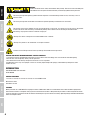 4
4
-
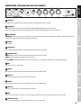 5
5
-
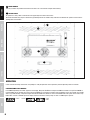 6
6
-
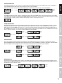 7
7
-
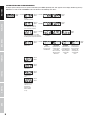 8
8
-
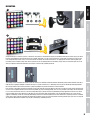 9
9
-
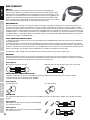 10
10
-
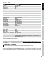 11
11
-
 12
12
-
 13
13
-
 14
14
-
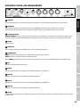 15
15
-
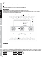 16
16
-
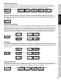 17
17
-
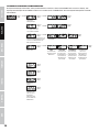 18
18
-
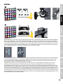 19
19
-
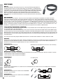 20
20
-
 21
21
-
 22
22
-
 23
23
-
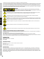 24
24
-
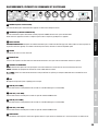 25
25
-
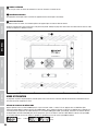 26
26
-
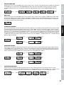 27
27
-
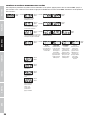 28
28
-
 29
29
-
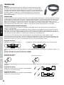 30
30
-
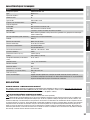 31
31
-
 32
32
-
 33
33
-
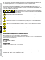 34
34
-
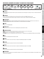 35
35
-
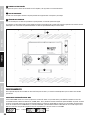 36
36
-
 37
37
-
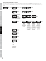 38
38
-
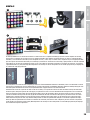 39
39
-
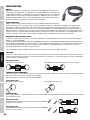 40
40
-
 41
41
-
 42
42
-
 43
43
-
 44
44
-
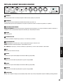 45
45
-
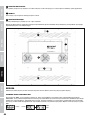 46
46
-
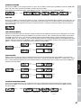 47
47
-
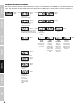 48
48
-
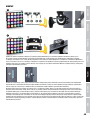 49
49
-
 50
50
-
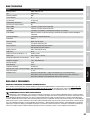 51
51
-
 52
52
-
 53
53
-
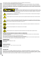 54
54
-
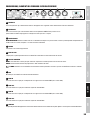 55
55
-
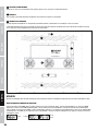 56
56
-
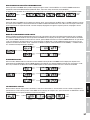 57
57
-
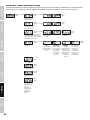 58
58
-
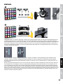 59
59
-
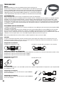 60
60
-
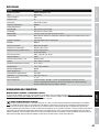 61
61
-
 62
62
-
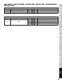 63
63
-
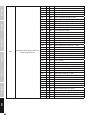 64
64
-
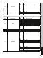 65
65
-
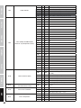 66
66
-
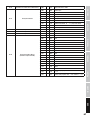 67
67
-
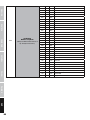 68
68
-
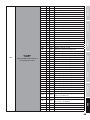 69
69
-
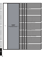 70
70
-
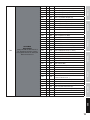 71
71
-
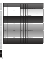 72
72
-
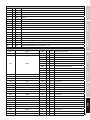 73
73
-
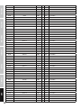 74
74
-
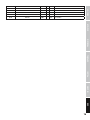 75
75
-
 76
76


Cameo CLMP10WRGB Manual de usuario
- Categoría
- Focos
- Tipo
- Manual de usuario
- Este manual también es adecuado para
en otros idiomas
- français: Cameo CLMP10WRGB Manuel utilisateur
- italiano: Cameo CLMP10WRGB Manuale utente
- Deutsch: Cameo CLMP10WRGB Benutzerhandbuch
- polski: Cameo CLMP10WRGB Instrukcja obsługi
Artículos relacionados
-
Cameo AURO® SPOT 200 Manual de usuario
-
Cameo CLCL200 Manual de usuario
-
-
Cameo Flash Matrix 250 El manual del propietario
-
-
-
-
-
-
Cameo SB 6T RDM Manual de usuario
