Eaton IF 1948 Guía de instalación

Tipo
Guía de instalación
Champ® Pro PLLA M2 Series Linear Emergency LED
Luminaire Fittings
Installation & Maintenance Information
SAVE THESE INSTRUCTIONS FOR FUTURE REFERENCE
IF 1948
IF 1948 • 10/22 Copyright © 2022, Eaton’s Crouse-Hinds Division Page 1
APPLICATION
CHAMP Pro Linear Emergency LED luminaire are suitable for use in the follow-
ing locations as dened by the National Electrical Code (NEC®):
The assembled luminaire shall be installed in accordance with the National
Electric Code NFPA70, and American Bureau of Shipping.
NEC
Wet location, IP66/67, Type 4X
UL Standards:
UL1598 Luminaires, UL1598A Marine
• UL8750
• UL924
CSA Standard:
CSA C22.2 No. 250
CSA C22.2 No. No.141
These luminaire housings shall be used with UL listed Crouse-Hinds ordinary
locations luminaire ttings namely LED Light Engine Cat Nos. PLLA*2 or
PLLA*4 series ending with M2 and Mounting means Cat Nos. M2-FLUSH-
MT-KIT, M2-CEILING-SWIVEL-KIT, M2-CEILING-WALL-KIT, M2-PM-KIT-1.25,
M2-PM-KIT-1.5, M2-PM-KIT-2.0, (refer to label provided inside the driver housing
for permissible tting details).
Refer to the luminaire tting nameplate for specic classication information,
maximum ambient temperature suitability, and corresponding operating
temperature (T-code).
The assembled linear LED luminaire is designed for use indoors and outdoors
in marine and wet locations, where moisture, dirt, corrosion, vibration and
rough usage may be present.
INPUT VOLTAGE:
UNV1: 120-277 VAC 50/60 Hz
1. Read carefully before installing and wiring luminaire and retain for future
reference.
2. The use of accessory equipment not recommended by the manufacturer
may cause an unsafe condition.
3. Use only replacement parts from Eatons Crouse Hinds division.
4. To avoid the risk of re, explosion or electric shock, this product should
be installed, inspected and maintained by a qualied electrician only, in
accordance with all applicable electrical codes.
5. Do not mount near gas or electric heaters.
6. Do not use this equipment for other than intended use.
7. Replace entire battery unit and LED driver when necessary. Contact the
manufacturer for information on service.
8. Do not attempt to service battery.
9. See product label for minimum supply wire temperature rating.
10. Battery requires 24hrs to fully charge. Allow 24 hours charging time
before depending on the battery to operate at full capacity.
11. The emergency battery requires a minimum charge time of one (1) hour
before testing the circuit, 24 hours is required for a full charge.
12. Equipment should be mounted in locations and at heights where it will
not readily be subjected to tampering by unauthorized personnel. Max.
mounting height: 25.2 feet)
13. The emergency luminaire is intended to be installed with CG-256 (issued
by the American Bureau of Shipping and Coast Guard.
14. This product must be installed in accordance with the applicable installa-
tion code by a person familiar with the construction and operation of the
product and the hazards involved.
IMPORTANT SAFEGUARDS - READ AND FOLLOW ALL SAFETY INSTRUCTIONS
STORAGE INSTRUCTIONS
1. EM luminaire must be stored in an ambient temperature range of 0°C
to 40°C.
2. Battery should be charged and discharged within 6 months. At a
minimum, the battery should be recharged within this time.
WARNING
To avoid electric shock:
Be certain electrical power is OFF before and during installation and
maintenance.
Luminaire must be supplied by a wiring system with an equipment
grounding conductor in accordance to the NEC and CEC for the specific
location involved.
To avoid burning hands:
Make sure lens and housing are cool when performing maintenance.
!
WARNING
To avoid explosion:
Make sure the supply voltage is the same as the luminaire voltage.
Do not operate in ambient temperatures above those indicated on the
luminaire nameplate.
Use proper supply wiring as specified on the luminaire nameplate.
All gasket seals must be clean and undamaged.
Before opening, electrical power to the luminaire must be turned off.
Keep tightly closed when in operation.
Clean only with damp cloth.
!
IMPORTANT SAFEGUARDS
When using electrical equipment, basic safety precautions should always be following including the
following:
IF 1948 • 10/22 Copyright © 2022, Eaton’s Crouse-Hinds Division Page 2
INSTALLATION
A. M2-FLUSH-MT-KIT
1. Make sure the power is disconnected to the conduit system before
installing the luminaire.
2. Install ush mount brackets to rear of luminaire driver housing using
the provided two (2) 1/4” hex bolts and split ring lock washers for each
bracket. Bracket orientation as shown in Figure 1. Torque to 64 in.-lbs (7.2
N-m)
3. Identify mounting location suitable for supporting luminaire, mark and drill
holes for ush brackets per dimensions shown in Figure 1.
4. Luminaire is now ready for mounting. It is strongly suggested to use
two (2) qualied tradespeople to proceed with the nal mounting of the
luminaire. This is recommended to avoid any personal injury or damage to
the luminaire.
5. Install and tighten four (4) 1/4” diameter fasteners (customer supplied) in
bracket mounting holes. It is recommended that stainless steel hardware
be used in locations with corrosion concerns.
Figure 1. Flush Ceiling Mount Installation
Length 2 Foot
(in)
2 Foot
(mm)
4 Foot
(in)
4 Foot
(mm)
A 24.0 610 39.0 991
B 24.25 616 24.25 616
C 2.50 63.5 2.50 63.5
THIRD ANGLE PROJECTION
B
C
A
660
26.0
A
123.2
4.85
175.3
6.90
1/4-20 x 1/2" HEX HEAD BOLT
1/2" SPLIT LOCK WASHER
ZONE
NO.
DESCRIPTION
DATE
APPRD.
LTR. NO.
CCHSY-SW-Template-D
SW_REV 11/2015
DO NOT SCALE DRAWING
NOTES:
1.
A
B
C
D
12
3
4
5
6
7
8
A
D
C
B
8765432 1
Your name
ASSY2
CAT2
CAT1
ASSY1
ARE IN
MILLIMETERS.
DIMENSIONS IN [ ] ARE IN
ALL PRIMARY DIMENSIONS
UNLESS OTHERWISE SPECIFIED,
MM/DD/YYYY
Your Name
WITH ASME Y14.5 2009.
DIM AND TOL IN ACCORDANCE
±
±
±
±
.1
.3
INCHES.
rev
0000000
WT. 15.84 LB
SCALE 1:2
FIRST MADE FOR Catalog Family
Title Line 1
APPROVED BY
DRAWN BY
Finish
... THICK
Material
mm
in.
.13
.000
1.5
Your Name
THIS IS PROPERTY OF EATON AND CONTAINS CONFIDENTIAL AND
TRADE SECRET INFORMATION. POSSESSION DOES NOT CONVEY
ANY RIGHTS TO LOAN, SELL OR DISCLOSE SAID INFORMATION.
REPRODUCTION OR USE FOR ANY PURPOSE OTHER THAN WHICH
IT WAS SUPPLIED MAY NOT BE MADE WITHOUT EXPRESS
WRITTEN PERMISSION OF EATON. THIS DRAWING IS ON LOAN
AND IS TO BE RETURNED UPON REQUEST.
Title Line 2
Your Name
MM/DD/YYYY
1.5
±
.005
±
.01
±
±
ANGLES
.XXX
.XX
.X
REDRAWN DATE
ORIGINAL DATE
UNLESS OTHERWISE SPECIFIED
TOLERANCES
MATERIAL:
FINISH:
APPROVED BY
CHECKED BY
USED ON
APPLICATION
NEXT ASSY.
TITLE
CODE IDENT. NO.
SIZE
REV.
D
SHEET 1 OF 5
CODE ...
INSTALLATION
Max. mounting height of 25.2 ft (7.68m)
B. M2-CEILING-WALL-KT
1. Make sure the power is disconnected to the conduit system before
installing the luminaire.
2. Mark and drill holes for fastening end brackets. Use two (2) 1/4” diameter
fasteners (customer supplied) at center to center measurements (see
Figure 2). It is recommended that stainless steel hardware be used in
locations with corrosion concerns.
3. Luminaire is now ready for mounting. It is strongly suggested to use
two (2) qualied tradespeople to proceed with the nal mounting of the
luminaire. This is recommended to avoid any personal injury or damage to
the luminaire.
4. For end mount wall/ceiling mounting brackets, it is recommended to
mount one bracket rst and then, while supporting the luminaire, insert it
into the mounted bracket, then attach the other bracket.
5. Aim the luminaire to achieve desired light output and tighten the 1/4” set
screws on brackets. Torque to 64 in.-lbs. (7.2 N-m).
6. Use set screw to limit rotation of the luminaire.
Figure 2. Ceiling-Wall Mount Installation
Length 2 Foot
(in)
2 Foot
(mm)
4 Foot
(in)
4 Foot
(mm)
A 28.5 724 28.5 724
B 24.0 610 39.0 991
THIRD ANGLE PROJECTION
A
B
175.3
6.90
205.2
8.08
63.5
2.50
54
2.13
B
723
28.5
CCHSY-SW-Template-D
SW_REV 11/2015
DO NOT SCALE DRAWING
NOTES:
1.
A
B
C
D
12
3
4
5
6
7
8
A
D
C
B
8765432 1
Your name
ASSY2
CAT2
CAT1
ASSY1
ARE IN
MILLIMETERS.
DIMENSIONS IN [ ] ARE IN
ALL PRIMARY DIMENSIONS
UNLESS OTHERWISE SPECIFIED,
MM/DD/YYYY
Your Name
WITH ASME Y14.5 2009.
DIM AND TOL IN ACCORDANCE
±
±
±
±
.1
.3
INCHES.
rev
0000000
WT. 15.84 LB
SCALE 1:2
FIRST MADE FOR Catalog Family
Title Line 1
APPROVED BY
DRAWN BY
Finish
... THICK
Material
mm
in.
.13
.000
1.5
Your Name
THIS IS PROPERTY OF EATON AND CONTAINS CONFIDENTIAL AND
TRADE SECRET INFORMATION. POSSESSION DOES NOT CONVEY
ANY RIGHTS TO LOAN, SELL OR DISCLOSE SAID INFORMATION.
REPRODUCTION OR USE FOR ANY PURPOSE OTHER THAN WHICH
IT WAS SUPPLIED MAY NOT BE MADE WITHOUT EXPRESS
WRITTEN PERMISSION OF EATON. THIS DRAWING IS ON LOAN
AND IS TO BE RETURNED UPON REQUEST.
Title Line 2
Your Name
MM/DD/YYYY
1.5
±
.005
±
.01
±
±
ANGLES
.XXX
.XX
.X
REDRAWN DATE
ORIGINAL DATE
UNLESS OTHERWISE SPECIFIED
TOLERANCES
MATERIAL:
FINISH:
APPROVED BY
CHECKED BY
USED ON
APPLICATION
NEXT ASSY.
TITLE
CODE IDENT. NO.
SIZE
REV.
D
SHEET 2 OF 5
CODE ...
!
WARNING
To avoid injury to personnel, do not let the luminaire hang or ex on one
bracket at a time. Failing to comply will result in breakage of bracket and
possible injury or death.
!
WARNING
To avoid injury to personnel, do not let the luminaire hang or ex on one
bracket at a time. Failing to comply will result in breakage of bracket and
possible injury or death.
C. M2-CEILING-SWIVEL-KIT
1. Make sure the power is disconnected to the conduit system before
installing the luminaire.
2. Identify mounting location suitable for supporting the luminaire, mark and
drill holes for fastening swivel brackets per center-to-center dimension ‘A
in table below (see Figure 3).
3. Mount swivel bracket assemblies to luminaire driver housing as shown
in Figure 3. Use two (2) of the provided 1/4” hex bolts and split ring lock
washers for each bracket. Torque to 64 in-lb (7.2 N-m).
4. Luminaire is now ready for mounting. It is strongly suggested to use
two (2) qualied tradespeople to proceed with the nal mounting of the
luminaire. This is recommended to avoid any personal injury or damage to
the luminaire.
5. Install and tighten 1/4” diameter fasteners (customer supplied) in each
of the bracket mounting holes. It is recommended that stainless steel
hardware be used in locations with corrosion concerns.
6. Adjust the position of the luminaire to the desired angle and tighten the
two (2) 5/16” pivot bolts snugly to the bracket and then tighten hex nuts.
Torque to 120 in.-lbs. (13.6 N-m).
IF 1948 • 10/22 Copyright © 2022, Eaton’s Crouse-Hinds Division Page 3
Length 2 Foot
(in)
2 Foot
(mm)
4 Foot
(in)
4 Foot
(mm)
A 26.4 670 26.4 670
B 24.0 610 39.0 991
Figure 3. Ceiling-Swivel Mount Installation
THIRD ANGLE PROJECTION
166.9
6.57
175.3
6.90
A
B
B
669.3
26.35
1/4" SPLIT LOCK WASHER
1/4-20 x 1/2" CAP SCREW
CCHSY-SW-Template-D
SW_REV 11/2015
DO NOT SCALE DRAWING
NOTES:
1.
A
B
C
D
12
3
4
5
6
7
8
A
D
C
B
8765432 1
Your name
ASSY2
CAT2
CAT1
ASSY1
ARE IN
MILLIMETERS.
DIMENSIONS IN [ ] ARE IN
ALL PRIMARY DIMENSIONS
UNLESS OTHERWISE SPECIFIED,
MM/DD/YYYY
Your Name
WITH ASME Y14.5 2009.
DIM AND TOL IN ACCORDANCE
±
±
±
±
.1
.3
INCHES.
rev
0000000
WT. 15.84 LB
SCALE 1:2
FIRST MADE FOR Catalog Family
Title Line 1
APPROVED BY
DRAWN BY
Finish
... THICK
Material
mm
in.
.13
.000
1.5
Your Name
THIS IS PROPERTY OF EATON AND CONTAINS CONFIDENTIAL AND
TRADE SECRET INFORMATION. POSSESSION DOES NOT CONVEY
ANY RIGHTS TO LOAN, SELL OR DISCLOSE SAID INFORMATION.
REPRODUCTION OR USE FOR ANY PURPOSE OTHER THAN WHICH
IT WAS SUPPLIED MAY NOT BE MADE WITHOUT EXPRESS
WRITTEN PERMISSION OF EATON. THIS DRAWING IS ON LOAN
AND IS TO BE RETURNED UPON REQUEST.
Title Line 2
Your Name
MM/DD/YYYY
1.5
±
.005
±
.01
±
±
ANGLES
.XXX
.XX
.X
REDRAWN DATE
ORIGINAL DATE
UNLESS OTHERWISE SPECIFIED
TOLERANCES
MATERIAL:
FINISH:
APPROVED BY
CHECKED BY
USED ON
APPLICATION
NEXT ASSY.
TITLE
CODE IDENT. NO.
SIZE
REV.
D
SHEET 3 OF 5
CODE ...
D. M2-PM-KIT-*
1. Make sure the power is disconnected to the conduit system before
installing the luminaire.
2. Verify that the clamp internal diameter is consistent with the diameter of
the pole prior to installation. Clamps are available in 1.65 (42mm), 2.00
(51mm) and 2.36 (60mm) sizes (see Figure 5).
3. Pole mount brackets are spaced 20.75” on the bracket centerlines as
shown in Figure 4.
4. Tighten two (2) of the provided 1/4” hex bolts and split ring lock washers
on each bracket sub-assembly. Torque to 64 in-lbs (7.2 N-m).
5. Remove the two (2) 5/16” screws, lock washers and nuts on each clamp
and remove the upper clamp halves.
6. Luminaire is now ready for mounting. It is strongly suggested to use
two (2) qualied tradespeople to proceed with the nal mounting of the
luminaire. This is recommended to avoid any personal injury or damage to
the luminaire.
7. Lift luminaire into position such that the pole ts into the lower clamp
halves.
8. Install the two (2) upper clamp halves and the 5/16” screws, lock washers
and nuts on each clamp.
9. Tighten the nuts on the 5/16” screws evenly using a back and forth
sequence. Torque to 120 in.-lbs. (13.6 N-m).
Cat. # Conguration
Dimension (inches)
A B C D
M2-PM-KIT-1.25 PM Kit 2.0 (trade
size 2”) 4.331 3.543 2.36 1.693
M2-PM-KIT-1.5 PM Kit 1.5 (trade
size 1 - 1/2”) 3.740 2.953 2.00 1.535
M2-PM-KIT-2.0 PM Kit 1.25 (trade
size 1 - 1/14”) 3.386 2.598 1.65 1.378
Length 2 Foot
(in)
2 Foot
(mm)
4 Foot
(in)
4 Foot
(mm)
A 24.0 610 39.0 991
B See table below for pipe clamp diameters
Figure 4. Pole Mount Installation
Figure 5. Pole Mount Details
THIRD ANGLE PROJECTION
A
527.1
20.75
A
171
6.7
B
175.3
6.90
198
7.8
A
C
D
B
CCHSY-SW-Template-D
SW_REV 11/2015
DO NOT SCALE DRAWING
NOTES:
1.
A
B
C
D
12
3
4
5
6
7
8
A
D
C
B
8765432 1
Your name
ASSY2
CAT2
CAT1
ASSY1
ARE IN
MILLIMETERS.
DIMENSIONS IN [ ] ARE IN
ALL PRIMARY DIMENSIONS
UNLESS OTHERWISE SPECIFIED,
MM/DD/YYYY
Your Name
WITH ASME Y14.5 2009.
DIM AND TOL IN ACCORDANCE
±
±
±
±
.1
.3
INCHES.
rev
0000000
WT. 15.84 LB
SCALE 1:2
FIRST MADE FOR Catalog Family
Title Line 1
APPROVED BY
DRAWN BY
Finish
... THICK
Material
mm
in.
.13
.000
1.5
Your Name
THIS IS PROPERTY OF EATON AND CONTAINS CONFIDENTIAL AND
TRADE SECRET INFORMATION. POSSESSION DOES NOT CONVEY
ANY RIGHTS TO LOAN, SELL OR DISCLOSE SAID INFORMATION.
REPRODUCTION OR USE FOR ANY PURPOSE OTHER THAN WHICH
IT WAS SUPPLIED MAY NOT BE MADE WITHOUT EXPRESS
WRITTEN PERMISSION OF EATON. THIS DRAWING IS ON LOAN
AND IS TO BE RETURNED UPON REQUEST.
Title Line 2
Your Name
MM/DD/YYYY
1.5
±
.005
±
.01
±
±
ANGLES
.XXX
.XX
.X
REDRAWN DATE
ORIGINAL DATE
UNLESS OTHERWISE SPECIFIED
TOLERANCES
MATERIAL:
FINISH:
APPROVED BY
CHECKED BY
USED ON
APPLICATION
NEXT ASSY.
TITLE
CODE IDENT. NO.
SIZE
REV.
D
SHEET 4 OF 5
CODE ...
!
WARNING
To avoid injury to personnel, do not let the luminaire hang or ex on one
bracket at a time. Failing to comply will result in breakage of bracket and
possible injury or death.
!
WARNING
To avoid injury to personnel, do not let the luminaire hang or ex on one
bracket at a time. Failing to comply will result in breakage of bracket and
possible injury or death.
IF 1948 • 10/22 Copyright © 2022, Eaton’s Crouse-Hinds Division Page 4
E. PENDANT MOUNT INSTRUCTIONS
1. Make sure the power is disconnected from the conduit system before
installing the luminaire
2. For Pendant Mount the conduit should be located in line with the 3/4”
NPT entry on the rear of the luminaire driver housing (see Figure 6).
3. Luminaire is ready for mounting. It is strongly suggested to use two (2)
qualied tradespeople to proceed with the nal mounting of the luminaire.
This is recommended to avoid any personal injury or damage to the
luminaire.
4. Verify sufcient quantity of Eatons STL thread lubricant is on conduit
entries and that all unused conduit entries on the end caps are closed
with lubricated plugs (see Figure 13).
5. Engage threaded conduit in rear driver housing NPT entry and fully tighten
in to desired position for operations (engage at least 3-1/2 threads).
6. Tighten set screws on driver housing as shown in Figure 8. Torque set
screws to 20 in-lb (2.3 N-m).
7. Luminaire now ready to make electrical connections. See section titled
Wiring The LED Luminaire for detailed instructions.
Length 2 Foot
(in)
2 Foot
(mm)
4 Foot
(in)
4 Foot
(mm)
A 24.0 610 39.0 991
Figure 6. Pendant Mount Detail View
Figure 7. Pendant Mount Set Screw Detail
A
175.3
6.90
112.9
4.45
THIRD ANGLE PROJECTION
A
THREADED CONDUIT
(3/4" NPT STANDARD)
175.3
6.90
112.9
4.45
CCHSY-SW-Template-D
SW_REV 11/2015
DO NOT SCALE DRAWING
NOTES:
1.
A
B
C
D
12
3
4
5
6
7
8
A
D
C
B
8765432 1
Your name
ASSY2
CAT2
CAT1
ASSY1
ARE IN
MILLIMETERS.
DIMENSIONS IN [ ] ARE IN
ALL PRIMARY DIMENSIONS
UNLESS OTHERWISE SPECIFIED,
MM/DD/YYYY
Your Name
WITH ASME Y14.5 2009.
DIM AND TOL IN ACCORDANCE
±
±
±
±
.1
.3
INCHES.
rev
0000000
WT. 15.84 LB
SCALE 1:2
FIRST MADE FOR Catalog Family
Title Line 1
APPROVED BY
DRAWN BY
Finish
... THICK
Material
mm
in.
.13
.000
1.5
Your Name
THIS IS PROPERTY OF EATON AND CONTAINS CONFIDENTIAL AND
TRADE SECRET INFORMATION. POSSESSION DOES NOT CONVEY
ANY RIGHTS TO LOAN, SELL OR DISCLOSE SAID INFORMATION.
REPRODUCTION OR USE FOR ANY PURPOSE OTHER THAN WHICH
IT WAS SUPPLIED MAY NOT BE MADE WITHOUT EXPRESS
WRITTEN PERMISSION OF EATON. THIS DRAWING IS ON LOAN
AND IS TO BE RETURNED UPON REQUEST.
Title Line 2
Your Name
MM/DD/YYYY
1.5
±
.005
±
.01
±
±
ANGLES
.XXX
.XX
.X
REDRAWN DATE
ORIGINAL DATE
UNLESS OTHERWISE SPECIFIED
TOLERANCES
MATERIAL:
FINISH:
APPROVED BY
CHECKED BY
USED ON
APPLICATION
NEXT ASSY.
TITLE
CODE IDENT. NO.
SIZE
REV.
D
SHEET 5 OF 5
CODE ...
SECONDARY SUPPORT
If using secondary support, attach one end of the support cable to one of the
four (4) attachment points provided on the luminaire driver housing and secure
the other end to a xed support. Use a minimum of two (2) support cables per
luminaire, securing a single cable at two (2) locations on the exterior of the
luminaire driver housing.
Arrange the secondary support cables to limit the suspended vertical distance
to no more than 18 inches from the primary mounted position. Cables must
be installed in this manner to limit the potential vertical drop to 18 inches
maximum.
PUSH-TO-TEST SWITCH
A remote push-to-test switch (not supplied) suitable for the classied area
must be wired in the supply circuit to periodically test the emergency operation
feature (see wiring diagrams). The switch used must be suitable for the area
classications.
STATUS INDICATOR LIGHT
The status indicator light located on LED board (Red LED) will be ON“
when the battery is charging. If the status LED is ashing, replace
emergency driver unit.. If required customer can remote mount their own
status indicator light with suitable electrical ratings. Contact Eaton’s
Crouse-Hinds for additional support.
For remote mounting of Status Indicator light refer to gure below “Remote
mounting Test switch & Status indicator”.
Important instructions for remote mounting of push to test switch (customer
supplied):
a. Switch shall be installed using acceptable wiring methods for the areas
involved in accordance with the NEC.
b. Switch shall be connected to the emergency luminaire circuit such that
when depressed it provides a transfer function and disconnects and
isolates the normal input from the emergency input.
c. Switch shall be identied as to its function (i.e. – marked “Emergency
Luminaire Test Switch”).
d. Switch shall have electrical ratings suitable for the emergency luminaires.
e. Switch shall be manually operated type.
f. Switch shall be of Momentary-contact type.
g. Switch must be visible and accessible without the use of tools.
Figure 8 Remote mounting test switch and status indicator
EMERGENCY DRIVER UNIT INFORMATION
Champ Pro Emergency Linear LED luminaires are supplied with an emergency
driver unit. Disconnect the battery converter connector (Red-Red wires)
prior to performing maintenance (Refer to Figures 14A, 14B or 14C). This will
disconnect the charged battery from the LEDs. The emergency driver unit must
be checked periodically to ensure that it is working properly.
IMPORTANT INSTRUCTIONS (for customer supplied wall switch)
1. Installations in which a remote wall switch is to be used, connect an
unswitched supply line to the Black wire (L) and a switched supply line to
the White/Red wire (L1) of the Emergency Backup Module. Refer to wall
switch connection details on Wiring Diagrams in Figures 14A, 14B and
14C.
2. When the switched supply line (L1) is de-energized using the wall switch,
the luminaire will turn off light output while the battery circuit remains
active and charging.
3. Upon the loss of line power to the Emergency BackupModule, the
luminaire will immediately operate in Emergency Operations mode
(automatic switching) with a reduced light output .
4. If the unswitched supply line is connected to Black wire (L) only, battery
will charge, and luminaire will be in OFF condition (i.e AC driver is not in
operating condition). This is the Emergency Operations Only mode and
the luminaire shall only be illuminated on the loss of the line power.
5. The wall switch used shall be suitable for 120 - 277VAC and ≥15A
operations.
Threaded conduit - 3/4" NPT
standard (not provided by
Eatons Crouse-Hinds)
WIRING THE LED LUMINAIRE
1. Assembly sequence is common to both the Pro PLLA2 and Pro PLLA4
LED luminaire products. The Pro PLLA2 luminaire is used in the supporting
illustrations.
2. To gain access to the luminaire input wiring connections loosen the eight
(8) #10-32 x .75” stainless steel cover screws (see Figure 9) until screws
are free from driver housing. Screws are a captive type and should not be
fully removed from the light engine tting assembly.
3. Pull the retention clips on the light engine assembly to free it from the
driver housing and pivot the light engine tting on the driver housing
service hooks (see Figure 10). This shall expose the internal volume of the
driver housing and the input wiring terminal carriers.
4. Connections to the LED light engine and LED driver are pre-wired and
do not require any further processing. Route the Line, Neutral and
Ground input wires to the wire terminal carrier (see Figure 11) and make
connections per system wiring diagrams (see Figures 14A, 14B and
14C) using methods that comply with all applicable codes. Terminate the
equipment grounding connector (green) rst, the common (white) next,
and nally, the line voltage (black). Ensure all electrical connections have
been completed and terminal block lever locks are fully seated and secure.
Note- standard entries in driver housing and 3/4” NPT thread.
5. Connect module battery connections (white wires) as the battery is
shipped disconnected to prevent discharging.
6. Connect Emergency Backup Module converter connection (Red wires) as
the last electrical connection. This connection enables electrical function in
the backup module and failure to make this connection will result in non-
function of the luminaire.
7. If using the dimming function of the LED driver, use only wires rated to
600V minimum. Dimming circuit operates on 0-10 VDC; dimmer shall be
suitably certied for the intended installation environment (e.g. Hazardous,
Ordinary Locations, etc...).
8. Re-install the light engine tting and tighten all eight (8) cover mounting
screws 23 in.-lbs. (2.6 N-m) using the bolting sequence directed in Figure
9. Verify that no luminaire wiring is pinched or trapped between light
engine and driver housing. Start all screws prior to tightening.
9. Replace any damaged or missing cover screws. Consult factory for
replacement parts.
WIRING INSTALLATION CHECKLIST
1. Verify sufcient quantity of Eatons STL thread lubricant is on conduit
entries and that all unused conduit entries on the end caps are closed
with lubricated plugs (see Figure 13).
2. Verify conduit is installed to at least ve (5) full threads into the end cap
conduit entries. Recommend approximately 1/8” bead quantity of Eatons
STL thread lubricant on conduit entries.
3. Verify installed conduit is torqued to 42-52 ft.-lbs. (57-71 N-m) for 3/4”
plug.
4. Verify supply wires are connected to luminaire wire leads per Figure 14A,
Figure 14B or Figure 14C.
5. Verify all electrical connections are properly made and secure.
6. Verify all wires are routed correctly and are fully contained in the driver
housing without any wires being pinched when the light engine tting
is rotated back into position. Re-attach driver cover to luminaire driver
housing using the bolt tightening sequence in Figure 9.
7. Verify captive attachment screws are tightened to 23 in.-lbs. (2.6 N-m) and
light engine tting is in ush contact with driver housing.
IF 1948 • 10/22 Copyright © 2022, Eaton’s Crouse-Hinds Division Page 5
Figure 13. NPT Fitting
Figure 9. Driver Housing Screw Locations
Figure 10. Light Engine Rotated for Servicing
Figure 11. Input Wiring Terminal Carrier
Figure 12. Driver Housing Safety Cable Mounting Locations
NOTE
A maximum of 8 luminaires may be daisy chained on a single circuit. See
luminaire wiring diagrams.
THIRD ANGLE PROJECTION
CCHSY-SW-Template-D
SW_REV 11/2015
DO NOT SCALE DRAWING
NOTES:
1.
A
B
C
D
12
3
4
5
6
7
8
A
D
C
B
8765432 1
Your name
ASSY2
CAT2
CAT1
ASSY1
ARE IN
MILLIMETERS.
DIMENSIONS IN [ ] ARE IN
ALL PRIMARY DIMENSIONS
UNLESS OTHERWISE SPECIFIED,
MM/DD/YYYY
Your Name
WITH ASME Y14.5 2009.
DIM AND TOL IN ACCORDANCE
±
±
±
±
.1
.3
INCHES.
rev
0000000
WT. 15.85 LB
SCALE 2:3
FIRST MADE FOR Catalog Family
Title Line 1
APPROVED BY
DRAWN BY
Finish
... THICK
Material
mm
in.
.13
.000
1.5
Your Name
THIS IS PROPERTY OF EATON AND CONTAINS CONFIDENTIAL AND
TRADE SECRET INFORMATION. POSSESSION DOES NOT CONVEY
ANY RIGHTS TO LOAN, SELL OR DISCLOSE SAID INFORMATION.
REPRODUCTION OR USE FOR ANY PURPOSE OTHER THAN WHICH
IT WAS SUPPLIED MAY NOT BE MADE WITHOUT EXPRESS
WRITTEN PERMISSION OF EATON. THIS DRAWING IS ON LOAN
AND IS TO BE RETURNED UPON REQUEST.
Title Line 2
Your Name
MM/DD/YYYY
1.5
±
.005
±
.01
±
±
ANGLES
.XXX
.XX
.X
REDRAWN DATE
ORIGINAL DATE
UNLESS OTHERWISE SPECIFIED
TOLERANCES
MATERIAL:
FINISH:
APPROVED BY
CHECKED BY
USED ON
APPLICATION
NEXT ASSY.
TITLE
CODE IDENT. NO.
SIZE
REV.
D
SHEET 6 OF 6
CODE ...
5
6
7
824
31
THIRD ANGLE PROJECTION
CCHSY-SW-Template-D
SW_REV 11/2015
DO NOT SCALE DRAWING
NOTES:
1.
A
B
C
D
12
3
4
5
6
7
8
A
D
C
B
8765432 1
Your name
ASSY2
CAT2
CAT1
ASSY1
ARE IN
MILLIMETERS.
DIMENSIONS IN [ ] ARE IN
ALL PRIMARY DIMENSIONS
UNLESS OTHERWISE SPECIFIED,
MM/DD/YYYY
Your Name
WITH ASME Y14.5 2009.
DIM AND TOL IN ACCORDANCE
±
±
±
±
.1
.3
INCHES.
rev
0000000
WT. 15.85 LB
SCALE 2:3
FIRST MADE FOR Catalog Family
Title Line 1
APPROVED BY
DRAWN BY
Finish
... THICK
Material
mm
in.
.13
.000
1.5
Your Name
THIS IS PROPERTY OF EATON AND CONTAINS CONFIDENTIAL AND
TRADE SECRET INFORMATION. POSSESSION DOES NOT CONVEY
ANY RIGHTS TO LOAN, SELL OR DISCLOSE SAID INFORMATION.
REPRODUCTION OR USE FOR ANY PURPOSE OTHER THAN WHICH
IT WAS SUPPLIED MAY NOT BE MADE WITHOUT EXPRESS
WRITTEN PERMISSION OF EATON. THIS DRAWING IS ON LOAN
AND IS TO BE RETURNED UPON REQUEST.
Title Line 2
Your Name
MM/DD/YYYY
1.5
±
.005
±
.01
±
±
ANGLES
.XXX
.XX
.X
REDRAWN DATE
ORIGINAL DATE
UNLESS OTHERWISE SPECIFIED
TOLERANCES
MATERIAL:
FINISH:
APPROVED BY
CHECKED BY
USED ON
APPLICATION
NEXT ASSY.
TITLE
CODE IDENT. NO.
SIZE
REV.
D
SHEET 6 OF 6
CODE ...
THIRD ANGLE PROJECTION
CCHSY-SW-Template-D
SW_REV 11/2015
DO NOT SCALE DRAWING
NOTES:
1.
A
B
C
D
12
3
4
5
6
7
8
A
D
C
B
8765432 1
Your name
ASSY2
CAT2
CAT1
ASSY1
ARE IN
MILLIMETERS.
DIMENSIONS IN [ ] ARE IN
ALL PRIMARY DIMENSIONS
UNLESS OTHERWISE SPECIFIED,
MM/DD/YYYY
Your Name
WITH ASME Y14.5 2009.
DIM AND TOL IN ACCORDANCE
±
±
±
±
.1
.3
INCHES.
rev
0000000
WT. 15.59 LB
SCALE 1:1
FIRST MADE FOR Catalog Family
Title Line 1
APPROVED BY
DRAWN BY
Finish
... THICK
Material
mm
in.
.13
.000
1.5
Your Name
THIS IS PROPERTY OF EATON AND CONTAINS CONFIDENTIAL AND
TRADE SECRET INFORMATION. POSSESSION DOES NOT CONVEY
ANY RIGHTS TO LOAN, SELL OR DISCLOSE SAID INFORMATION.
REPRODUCTION OR USE FOR ANY PURPOSE OTHER THAN WHICH
IT WAS SUPPLIED MAY NOT BE MADE WITHOUT EXPRESS
WRITTEN PERMISSION OF EATON. THIS DRAWING IS ON LOAN
AND IS TO BE RETURNED UPON REQUEST.
Title Line 2
Your Name
MM/DD/YYYY
1.5
±
.005
±
.01
±
±
ANGLES
.XXX
.XX
.X
REDRAWN DATE
ORIGINAL DATE
UNLESS OTHERWISE SPECIFIED
TOLERANCES
MATERIAL:
FINISH:
APPROVED BY
CHECKED BY
USED ON
APPLICATION
NEXT ASSY.
TITLE
CODE IDENT. NO.
SIZE
REV.
D
SHEET 7 OF 7
CODE ...
Figure 14A. 2 Foot UNV1 Standard Wiring Diagram
Figure 14B. 4 Foot UNV1 Standard Wiring Diagram
WIRING DIAGRAMS
IF 1948 • 10/22 Copyright © 2022, Eaton’s Crouse-Hinds Division Page 6
MAINTENANCE GENERAL
Important Notes: Branch circuit eld wiring must be disconnected prior
to initial luminaire installation or maintenance. Before performing any
maintenance work with the luminaire enclosure open, the battery pack
must be disconnected from the converter/inverter assembly by separating
the latching connectors (connecting two white wires and two black and
red wires of battery). Also disconnect battery/converter connector (Red-
Red wires). See Figures 14A, 14B and 14C for connection location.
1. Disconnect the battery/converter connector during extended periods of
power loss of more than 1 week.
2. If luminaire is out of service for more than 1 year, perform annual test
procedure & replace battery packs as needed.
3. Perform visual, electrical and mechanical inspections on a regular basis.
The environment and frequency of use should determine this. However,
it is recommended that checks be made at least once a year. We
recommend an Electrical Preventive Maintenance Program as described
in the National Fire Protection Association Bulletin NFPA No. 70B:
Recommended Practice for Electrical Equipment Maintenance (www.
nfpa.org)
4. The lens should be cleaned periodically to ensure continued lighting
performance. To clean, wipe the lens with a clean, damp cloth. If this is
not enough, use a mild soap or a common liquid cleaner. Do not use an
abrasive, strong alkaline or acid cleaner. Damage may result.
5. Visually check for undue heating evidenced by discoloration of wires or
other components, damaged parts or leakage evidenced by water or
corrosion in the interior. Replace all worn, damaged or malfunctioning
components, and clean gasket seals before putting the luminaire back into
service.
6. Electrically check to make sure that all connections are clean and tight.
7. Mechanically check that all parts are properly assembled.
8. Check and re-torque all mounting hardware.
9. To prevent heat build-up, remove dust from the LED housing using a soft
brush or air pressure.
10. Visually inspect status indicator (charging) indicator light monthly. It
should be illuminated (when AC power ON). If indicator is ashing contact
tech support.
11. Test the emergency operations of the luminaire at 30-day intervals for
a minimum of 30 seconds. The LED load should operate at reduced
illumination in case of power failure
12. Conduct a 90 minute discharge test once a year. The LED load should
operate at reduced illumination for at least 90 minutes.
REPLACEMENT PARTS
(USE LISTED FITTINGS COVERED - LED DRIVERS,
MOUNTING OPTIONS, LED LIGHT ENGINE)
Eatons Crouse-Hinds series Champ Pro Linear Emergency LED luminaires are
designed to provide years of reliable lighting performance. However, should
the need for replacement parts arise, they are available through your authorized
Eatons Crouse-Hinds distributor. Assistance may also be obtained through your
local Eatons Crouse-Hinds representative or the Eatons Crouse-Hinds Sales
Service Department, 1201 Wolf Street, Syracuse, New York 13208, Phone
866-764-5454.
All statements, technical information and recommendations contained herein are based on information and tests we believe to be reliable. The accuracy or completeness thereof are not
guaranteed. In accordance with Eaton’s Crouse-Hinds Division’s “Terms and Conditions of Sale,” and since conditions of use are outside our control, the purchaser should determine
the suitability of the product for his intended use and assumes all risk and liability whatsoever in connection therewith.
Eatons Crouse-Hinds Division IF 1948
1201 Wolf Street Syracuse, NY 13208 • U.S.A. Revision 2
Copyright© 2022 New 10/22
Figure 14C. UNV1 w/Surge Option Wiring Diagram
LED lineal de emergencia Champ® Pro PLLA serie M2
Conexiones de luminarias
Información de instalación y mantenimiento
CONSERVE ESTAS INSTRUCCIONES PARA FUTURAS CONSULTAS
IF 1948
IF 1948 • 10/22 Copyright © 2022, División Crouse-Hinds de Eaton Página 8
APLICACIÓN
Las luminarias LED lineales de emergencia CHAMP Pro son adecuadas para
el uso en las siguientes ubicaciones como se dene en el Código Eléctrico
Nacional (NEC®, del inglés National Electrical Code):
La luminaria ensamblada debe instalarse según el Código Eléctrico Nacional
NFPA70 y la American Bureau of Shipping.
NEC
Ubicación húmeda, IP66/67, Tipo 4X
Estándares UL:
UL1598 Luminarias, UL1598A Marina
• UL8750
• UL924
Estándar CSA:
CSA C22.2 N.º 250
CSA C22.2 N.º 141
Estas cubiertas de luminarias se deben utilizar con conexiones de luminarias
de ubicaciones ordinarias Crouse-Hinds con certicación UL, a saber, motor
de luz LED con n.º de catálogo de la serie PLLA*2 o PLLA*4 que terminan
con M2 y medios de montaje con n.º de catálogo M2-FLUSH-MT-KIT,
M2-CEILING-SWIVEL-KIT, M2-CEILING-WALL-KIT, M2-PM-KIT-1.25,
M2-PM-KIT-1.5, M2-PM-KIT-2.0, (consulte la etiqueta que se proporciona dentro
de la cubierta del controlador para obtener detalles de accesorios permisibles).
Consulte la placa de identicación de la conexión de luminarias para obtener
información especíca de la clasicación, adecuación de temperatura ambiente
máxima y la temperatura de operación correspondiente (códigoT).
La luminaria LED lineal ensamblada está diseñada para su uso en interiores y
exteriores, en zonas marinas y húmedas, con presencia de humedad, suciedad,
corrosión, vibración o uso exigente.
VOLTAJE DE ENTRADA:
UNV1: 120-277 VCA 50/60Hz
1. Lea atentamente antes de instalar y cablear la luminaria y consérvelas
para futuras consultas.
2. El uso de equipos accesorios no recomendados por el fabricante puede
causar una condición insegura.
3. Solo utilice piezas de repuesto de la división Crouse Hinds de Eaton.
4. Para evitar el riesgo de incendios, explosiones o descargas eléctricas, solo
un electricista calicado debe instalar, inspeccionar y realizar mantenimiento
a este producto, de conformidad con los códigos eléctricos aplicables.
5. No montar cerca de calefactores eléctricos ni a gas.
6. No use este equipo para ningún uso distinto al previsto.
7. Reemplace toda la unidad de la batería y el controlador LED cuando
sea necesario. Comuníquese con el fabricante para recibir información
acerca del servicio.
8. No intente realizar el mantenimiento de la batería.
9. Consulte la etiqueta del producto para conocer la especicación mínima
de temperatura del cable de alimentación.
10. La batería requiere 24horas para cargarse completamente. El tiempo
de carga debe ser de 24horas, dependiendo de la batería, para que
funcione al máximo de su capacidad.
11. La batería de emergencia requiere un tiempo de carga mínimo de 1hora
antes de probar el circuito, se requieren 24horas para una carga completa.
12. El equipo debe montarse en ubicaciones y en alturas en donde no sea fácil
que lo manipule personal no autorizado.Altura de montaje máx.: 25,2ft)
13. La luminaria de emergencia está diseñada para que se instale con
CG-256 (emitido por la American Bureau of Shipping y la Guardia Costera
de Estados Unidos).
14. Este producto se debe instalar de acuerdo con el código de instalación
correspondiente por parte de una persona familiarizada con la construcción
y el funcionamiento del producto, así como los peligros inherentes.
MEDIDAS DE SEGURIDAD IMPORTANTES: LEA Y SIGA TODAS LAS INSTRUCCIONES DE SEGURIDAD
INSTRUCCIONES DE ALMACENAMIENTO
1. Las luminarias EM se deben almacenar en un rango de temperatura
ambiente de 0°C a 40°C.
2. La batería se debe cargar y descargar en un plazo de 6meses. Como
mínimo, la batería debe recargarse dentro de este plazo.
ADVERTENCIA
Para evitar descargas eléctricas:
Asegúrese de que la energía eléctrica esté DESCONECTADA antes y
durante la instalación y el mantenimiento.
Las luminarias se deben alimentar mediante un sistema de cableado con
un conductor de conexión a tierra para el equipo que cumpla las normas
del NEC y el CEC para las ubicaciones específicas involucradas.
Para evitar quemaduras en las manos:
Asegúrese de que los lentes y la cubierta se encuentren fríos al momento
de realizar el mantenimiento.
!
ADVERTENCIA
Para evitar una explosión:
Asegúrese de que el voltaje de alimentación sea el mismo que el voltaje
de la luminaria.
No la use a temperaturas ambientales por encima de las indicadas en la
placa de identificación de la luminaria.
Utilice un cableado de alimentación adecuado, como se indica en la placa
de identificación de la luminaria.
Todos los sellos de las juntas deben estar limpios y sin daños.
Antes de abrir, se debe desconectar la alimentación de la luminaria.
Manténgala herméticamente cerrada cuando se encuentre en funcionamiento.
Limpie solo con un paño húmedo.
!
MEDIDAS DE SEGURIDAD IMPORTANTES
Cuando utilice equipo eléctrico, se deben seguir siempre las precauciones de seguridad básicas,
incluido lo siguiente:
IF 1948 • 10/22 Copyright © 2022, División Crouse-Hinds de Eaton Página 9
INSTALACIÓN
A. M2-FLUSH-MT-KIT
1. Asegúrese de que la alimentación esté desconectada del sistema de
conductos antes de instalar la luminaria.
2. Instale los soportes de montaje empotrado en la parte trasera de la
cubierta del controlador de la luminaria con los dos (2) pernos hexagonales
de 1/4" y las arandelas de seguridad con anillo dividido para cada soporte.
Oriente el soporte como se muestra en la Figura1. Aplique un torque de
64in-lb (7,2N-m)
3. Identique la ubicación de montaje adecuada para instalar la luminaria,
marque y perfore los oricios para jar los soportes de montaje
empotrado, según las dimensiones que se muestran en la Figura1.
4. La luminaria ahora está lista para el montaje. Se recomienda
encarecidamente que use a dos (2) personas especializadas calicadas
para proceder con el montaje nal de la luminaria. Se recomienda esto
para evitar cualquier lesión personal o daño a la luminaria.
5. Instale y apriete cuatro (4) sujetadores de 1/4" de diámetro (suministrados
por el cliente) en los oricios de montaje del soporte. Se recomienda utilizar
accesorios de acero inoxidable en lugares con problemas de corrosión.
Figura 1. Instalación de montaje en techo
Longitud 2pies
(in)
2pies
(mm)
4pies
(in)
4pies
(mm)
A 24,0 610 39,0 991
B 24,25 616 24,25 616
C 2,50 63,5 2,50 63,5
THIRD ANGLE PROJECTION
B
C
A
660
26.0
A
123.2
4.85
175.3
6.90
1/4-20 x 1/2" HEX HEAD BOLT
1/2" SPLIT LOCK WASHER
ZONE
NO.
DESCRIPTION
DATE
APPRD.
LTR. NO.
CCHSY-SW-Template-D
SW_REV 11/2015
DO NOT SCALE DRAWING
NOTES:
1.
A
B
C
D
12
3
4
5
6
7
8
A
D
C
B
8765432 1
Your name
ASSY2
CAT2
CAT1
ASSY1
ARE IN
MILLIMETERS.
DIMENSIONS IN [ ] ARE IN
ALL PRIMARY DIMENSIONS
UNLESS OTHERWISE SPECIFIED,
MM/DD/YYYY
Your Name
WITH ASME Y14.5 2009.
DIM AND TOL IN ACCORDANCE
±
±
±
±
.1
.3
INCHES.
rev
0000000
WT. 15.84 LB
SCALE 1:2
FIRST MADE FOR Catalog Family
Title Line 1
APPROVED BY
DRAWN BY
Finish
... THICK
Material
mm
in.
.13
.000
1.5
Your Name
THIS IS PROPERTY OF EATON AND CONTAINS CONFIDENTIAL AND
TRADE SECRET INFORMATION. POSSESSION DOES NOT CONVEY
ANY RIGHTS TO LOAN, SELL OR DISCLOSE SAID INFORMATION.
REPRODUCTION OR USE FOR ANY PURPOSE OTHER THAN WHICH
IT WAS SUPPLIED MAY NOT BE MADE WITHOUT EXPRESS
WRITTEN PERMISSION OF EATON. THIS DRAWING IS ON LOAN
AND IS TO BE RETURNED UPON REQUEST.
Title Line 2
Your Name
MM/DD/YYYY
1.5
±
.005
±
.01
±
±
ANGLES
.XXX
.XX
.X
REDRAWN DATE
ORIGINAL DATE
UNLESS OTHERWISE SPECIFIED
TOLERANCES
MATERIAL:
FINISH:
APPROVED BY
CHECKED BY
USED ON
APPLICATION
NEXT ASSY.
TITLE
CODE IDENT. NO.
SIZE
REV.
D
SHEET 1 OF 5
CODE ...
INSTALACIÓN
ALTURA de montaje máx. de 7,68m (25,2ft)
B. M2-CEILING-WALL-KT
1. Asegúrese de que la alimentación esté desconectada del sistema de
conductos antes de instalar la luminaria.
2. Marque y taladre los oricios para sujetar los soportes de extremo. Use
dos (2) sujetadores de 1/4" de diámetro (suministrados por el cliente) en las
medidas de centro a centro (consulte la Figura2). Se recomienda utilizar
accesorios de acero inoxidable en lugares con problemas de corrosión.
3. La luminaria ahora está lista para el montaje. Se recomienda
encarecidamente que use a dos (2) personas especializadas calicadas
para proceder con el montaje nal de la luminaria. Se recomienda esto
para evitar cualquier lesión personal o daño a la luminaria.
4. Para los soportes de extremo de montaje en pared o techo, se recomienda
montar primero un soporte y, luego, mientras se sostiene la luminaria,
insertarlo en el soporte montado, para luego montar el otro soporte.
5. Oriente la luminaria para obtener la potencia de luz deseada y apriete los
tornillos de jación de 1/4" en los soportes. Aplique un torque de 64in-lb
(7,2N-m).
6. Use un tornillo de jación para limitar la rotación de la luminaria.
Figura 2. Instalación de montaje en pared o techo
Longitud 2pies
(in)
2pies
(mm)
4pies
(in)
4pies
(mm)
A 28,5 724 28,5 724
B 24,0 610 39,0 991
THIRD ANGLE PROJECTION
A
B
175.3
6.90
205.2
8.08
63.5
2.50
54
2.13
B
723
28.5
CCHSY-SW-Template-D
SW_REV 11/2015
DO NOT SCALE DRAWING
NOTES:
1.
A
B
C
D
12
3
4
5
6
7
8
A
D
C
B
8765432 1
Your name
ASSY2
CAT2
CAT1
ASSY1
ARE IN
MILLIMETERS.
DIMENSIONS IN [ ] ARE IN
ALL PRIMARY DIMENSIONS
UNLESS OTHERWISE SPECIFIED,
MM/DD/YYYY
Your Name
WITH ASME Y14.5 2009.
DIM AND TOL IN ACCORDANCE
±
±
±
±
.1
.3
INCHES.
rev
0000000
WT. 15.84 LB
SCALE 1:2
FIRST MADE FOR Catalog Family
Title Line 1
APPROVED BY
DRAWN BY
Finish
... THICK
Material
mm
in.
.13
.000
1.5
Your Name
THIS IS PROPERTY OF EATON AND CONTAINS CONFIDENTIAL AND
TRADE SECRET INFORMATION. POSSESSION DOES NOT CONVEY
ANY RIGHTS TO LOAN, SELL OR DISCLOSE SAID INFORMATION.
REPRODUCTION OR USE FOR ANY PURPOSE OTHER THAN WHICH
IT WAS SUPPLIED MAY NOT BE MADE WITHOUT EXPRESS
WRITTEN PERMISSION OF EATON. THIS DRAWING IS ON LOAN
AND IS TO BE RETURNED UPON REQUEST.
Title Line 2
Your Name
MM/DD/YYYY
1.5
±
.005
±
.01
±
±
ANGLES
.XXX
.XX
.X
REDRAWN DATE
ORIGINAL DATE
UNLESS OTHERWISE SPECIFIED
TOLERANCES
MATERIAL:
FINISH:
APPROVED BY
CHECKED BY
USED ON
APPLICATION
NEXT ASSY.
TITLE
CODE IDENT. NO.
SIZE
REV.
D
SHEET 2 OF 5
CODE ...
!
ADVERTENCIA
Para evitar provocar lesiones al personal, no deje la luminaria colgando
ni la exione en un soporte a la vez. El incumplimiento de las normas
provocará la rotura del soporte y, posiblemente, lesiones o la muerte.
!
ADVERTENCIA
Para evitar provocar lesiones al personal, no deje la luminaria colgando
ni la exione en un soporte a la vez. El incumplimiento de las normas
provocará la rotura del soporte y, posiblemente, lesiones o la muerte.
PERNO DE CABEZA HEXAGONAL DE 1/4-20 x 1/2"
ARANDELA ABIERTA DE BLOQUEO DE 1/2 in
175,3
6,90
123,2
4,85
26,0
6,90
175,3
205,2
8,08
2,50
63,5
28,5
2,13
660
54
723
C. M2-CEILING-SWIVEL-KIT
1. Asegúrese de que la alimentación esté desconectada del sistema de
conductos antes de instalar la luminaria.
2. Identique la ubicación de montaje adecuada para instalar la luminaria,
marque y perfore los oricios para jar los soportes giratorios de acuerdo con
la dimensión de centro a centro "A" en la tabla a continuación (ver Figura 3).
3. Monte los conjuntos de soporte giratorio en la cubierta del controlador de
la luminaria, como se muestra en la Figura3. Utilice dos (2) de los pernos
hexagonales de 1/4" proporcionados y arandelas de seguridad con anillo
dividido para cada soporte. Aplique un torque de 64in-lb (7,2N-m).
4. La luminaria ahora está lista para el montaje. Se recomienda
encarecidamente que use a dos (2) personas especializadas calicadas
para proceder con el montaje nal de la luminaria. Se recomienda esto
para evitar cualquier lesión personal o daño a la luminaria.
5. Instale y apriete los sujetadores de 1/4" de diámetro (suministrados
por el cliente) en cada uno de los oricios de montaje del soporte.
Se recomienda utilizar accesorios de acero inoxidable en lugares con
problemas de corrosión.
6. Ajuste la posición de la luminaria al ángulo deseado, ajuste los dos (2)
pernos de pivote de 5/16" rmemente al soporte y, luego, apriete las
tuercas hexagonales. Aplique un torque de 120in-lb (13,6N-m).
IF 1948 • 10/22 Copyright © 2022, División Crouse-Hinds de Eaton Página 10
Longitud 2pies
(in)
2pies
(mm)
4pies
(in)
4pies
(mm)
A 26,4 670 26,4 670
B 24,0 610 39,0 991
Figura 3. Instalación del montaje giratorio en techo
THIRD ANGLE PROJECTION
166.9
6.57
175.3
6.90
A
B
B
669.3
26.35
1/4" SPLIT LOCK WASHER
1/4-20 x 1/2" CAP SCREW
CCHSY-SW-Template-D
SW_REV 11/2015
DO NOT SCALE DRAWING
NOTES:
1.
A
B
C
D
12
3
4
5
6
7
8
A
D
C
B
8765432 1
Your name
ASSY2
CAT2
CAT1
ASSY1
ARE IN
MILLIMETERS.
DIMENSIONS IN [ ] ARE IN
ALL PRIMARY DIMENSIONS
UNLESS OTHERWISE SPECIFIED,
MM/DD/YYYY
Your Name
WITH ASME Y14.5 2009.
DIM AND TOL IN ACCORDANCE
±
±
±
±
.1
.3
INCHES.
rev
0000000
WT. 15.84 LB
SCALE 1:2
FIRST MADE FOR Catalog Family
Title Line 1
APPROVED BY
DRAWN BY
Finish
... THICK
Material
mm
in.
.13
.000
1.5
Your Name
THIS IS PROPERTY OF EATON AND CONTAINS CONFIDENTIAL AND
TRADE SECRET INFORMATION. POSSESSION DOES NOT CONVEY
ANY RIGHTS TO LOAN, SELL OR DISCLOSE SAID INFORMATION.
REPRODUCTION OR USE FOR ANY PURPOSE OTHER THAN WHICH
IT WAS SUPPLIED MAY NOT BE MADE WITHOUT EXPRESS
WRITTEN PERMISSION OF EATON. THIS DRAWING IS ON LOAN
AND IS TO BE RETURNED UPON REQUEST.
Title Line 2
Your Name
MM/DD/YYYY
1.5
±
.005
±
.01
±
±
ANGLES
.XXX
.XX
.X
REDRAWN DATE
ORIGINAL DATE
UNLESS OTHERWISE SPECIFIED
TOLERANCES
MATERIAL:
FINISH:
APPROVED BY
CHECKED BY
USED ON
APPLICATION
NEXT ASSY.
TITLE
CODE IDENT. NO.
SIZE
REV.
D
SHEET 3 OF 5
CODE ...
D. M2-PM-KIT-*
1. Asegúrese de que la alimentación esté desconectada del sistema de
conductos antes de instalar la luminaria.
2. Verique que el diámetro interno de la abrazadera coincida con el diámetro del
poste antes de la instalación. Las abrazaderas están disponibles en tamaños
de 1,65 (42mm), 2,00 (51mm) y 2,36 (60mm) (consulte la Figura5).
3. Los soportes de montaje en poste tienen una separación de 20,75" en las
líneas centrales del soporte, como se muestra en la Figura4.
4. Apriete dos (2) de los pernos hexagonales de 1/4" proporcionados y
arandelas de seguridad con anillo dividido en cada subconjunto de
soporte. Aplique un torque de 64in-lb (7,2 N-m).
5. Retire los dos (2) tornillos de 5/16", las arandelas de seguridad y las tuercas
de cada abrazadera y quite las mitades superiores de las abrazaderas.
6. La luminaria ahora está lista para el montaje. Se recomienda
encarecidamente que use a dos (2) personas especializadas calicadas
para proceder con el montaje nal de la luminaria. Se recomienda esto
para evitar cualquier lesión personal o daño a la luminaria.
7. Levante la luminaria en posición de tal manera que el poste encaje en las
mitades inferiores de las abrazaderas.
8. Instale las dos (2) mitades superiores de las abrazaderas y los tornillos de
5/16", las arandelas de seguridad y las tuercas en cada abrazadera.
9. Ajuste uniformemente las tuercas en los tornillos de 5/16in con una secuencia
hacia delante y hacia atrás. Aplique un torque de 120in-lb (13,6N-m).
N.º Cat Conguración
Dimensión (pulgadas)
A B C D
M2-PM-KIT-1.25
Kit PM 2.0
(tamaño
comercial2")
4,331 3,543 2,36 1,693
M2-PM-KIT-1.5
Kit PM 1.5
(tamaño comercial
1 - 1/2")
3,740 2,953 2,00 1,535
M2-PM-KIT-2.0
Kit PM 1.25
(tamaño comercial
1 - 1/14")
3,386 2,598 1,65 1,378
Longitud 2pies
(in)
2pies
(mm)
4pies
(in)
4pies
(mm)
A 24,0 610 39,0 991
BConsulte la siguiente tabla para conocer los
diámetros de las abrazaderas de tubo.
Figura 4. Instalación de montaje en poste
Figura 5. Detalles del montaje en poste
THIRD ANGLE PROJECTION
A
527.1
20.75
A
171
6.7
B
175.3
6.90
198
7.8
A
C
D
B
CCHSY-SW-Template-D
SW_REV 11/2015
DO NOT SCALE DRAWING
NOTES:
1.
A
B
C
D
12
3
4
5
6
7
8
A
D
C
B
8765432 1
Your name
ASSY2
CAT2
CAT1
ASSY1
ARE IN
MILLIMETERS.
DIMENSIONS IN [ ] ARE IN
ALL PRIMARY DIMENSIONS
UNLESS OTHERWISE SPECIFIED,
MM/DD/YYYY
Your Name
WITH ASME Y14.5 2009.
DIM AND TOL IN ACCORDANCE
±
±
±
±
.1
.3
INCHES.
rev
0000000
WT. 15.84 LB
SCALE 1:2
FIRST MADE FOR Catalog Family
Title Line 1
APPROVED BY
DRAWN BY
Finish
... THICK
Material
mm
in.
.13
.000
1.5
Your Name
THIS IS PROPERTY OF EATON AND CONTAINS CONFIDENTIAL AND
TRADE SECRET INFORMATION. POSSESSION DOES NOT CONVEY
ANY RIGHTS TO LOAN, SELL OR DISCLOSE SAID INFORMATION.
REPRODUCTION OR USE FOR ANY PURPOSE OTHER THAN WHICH
IT WAS SUPPLIED MAY NOT BE MADE WITHOUT EXPRESS
WRITTEN PERMISSION OF EATON. THIS DRAWING IS ON LOAN
AND IS TO BE RETURNED UPON REQUEST.
Title Line 2
Your Name
MM/DD/YYYY
1.5
±
.005
±
.01
±
±
ANGLES
.XXX
.XX
.X
REDRAWN DATE
ORIGINAL DATE
UNLESS OTHERWISE SPECIFIED
TOLERANCES
MATERIAL:
FINISH:
APPROVED BY
CHECKED BY
USED ON
APPLICATION
NEXT ASSY.
TITLE
CODE IDENT. NO.
SIZE
REV.
D
SHEET 4 OF 5
CODE ...
!
ADVERTENCIA
Para evitar provocar lesiones al personal, no deje la luminaria colgando
ni la exione en un soporte a la vez. El incumplimiento de las normas
provocará la rotura del soporte y, posiblemente, lesiones o la muerte.
!
ADVERTENCIA
Para evitar provocar lesiones al personal, no deje la luminaria colgando
ni la exione en un soporte a la vez. El incumplimiento de las normas
provocará la rotura del soporte y, posiblemente, lesiones o la muerte.
6,90
175,3
6,57
166,9
669,3
26,35
TORNILLO DE CABEZA DE 1/4-20 x 1/2"
ARANDELA ABIERTA DE BLOQUEO DE 1/4 in
6,90
175,3
171
6,7
7,8
198
527,1
20,75
IF 1948 • 10/22 Copyright © 2022, División Crouse-Hinds de Eaton Página 11
E. INSTRUCCIONES DE MONTAJE DEL COLGANTE
1. Asegúrese de que la alimentación esté desconectada del sistema de
conductos antes de instalar la luminaria
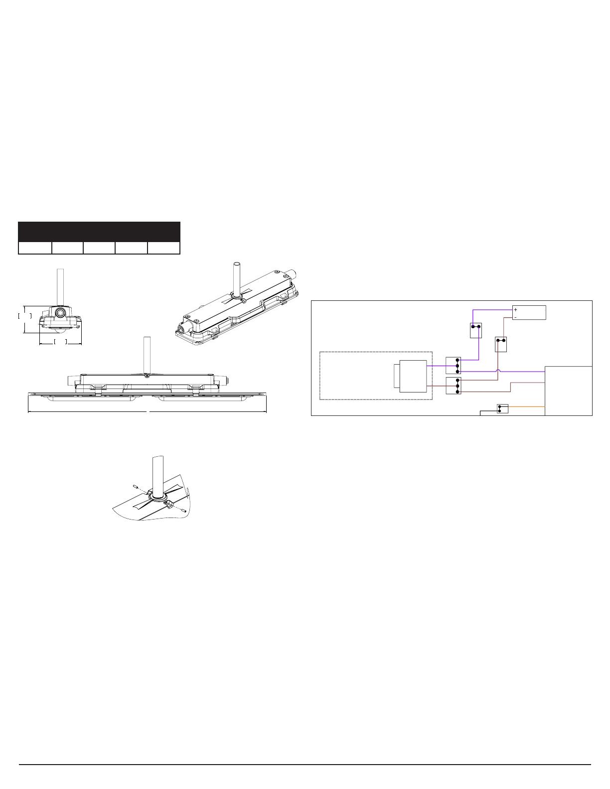
2. Para el montaje colgante, el conducto debe estar ubicado en línea con la
entrada NPT de 3/4" en la parte posterior de la cubierta del controlador de
la luminaria (consulte la Figura6).
3. La luminaria está lista para el montaje. Se recomienda encarecidamente
que use a dos (2) personas especializadas calicadas para proceder con
el montaje nal de la luminaria. Se recomienda esto para evitar cualquier
lesión personal o daño a la luminaria.
4. Verique que haya suciente lubricante para roscas STL de Eaton en las
entradas del conducto y que todas las entradas de conducto no usadas en
las cubiertas estén cerradas con tapones lubricados (consulte la Figura13).
5. Conecte el conducto roscado en la entrada NPT de la cubierta del
controlador trasero y apriete completamente en la posición deseada para
el funcionamiento (inserte, al menos, 3-1/2roscas).
6. Apriete los tornillos de jación en la cubierta del controlador, como se muestra
en la Figura8. Aplique un torque a los tornillos de jación de 20in-lb (2,3N-m).
7. La luminaria ahora está lista para que se hagan las conexiones eléctricas.
Consulte la sección denominada Cableado del sistema de iluminación LED
para obtener instrucciones detalladas.
Longitud 2pies
(in)
2pies
(mm)
4pies
(in)
4pies
(mm)
A 24,0 610 39,0 991
Figura 6. Vista detallada del montaje colgante
Figura 7. Detalle del tornillo de jación de montaje colgante
A
175.3
6.90
112.9
4.45
THIRD ANGLE PROJECTION
A
THREADED CONDUIT
(3/4" NPT STANDARD)
175.3
6.90
112.9
4.45
CCHSY-SW-Template-D
SW_REV 11/2015
DO NOT SCALE DRAWING
NOTES:
1.
A
B
C
D
12
3
4
5
6
7
8
A
D
C
B
8765432 1
Your name
ASSY2
CAT2
CAT1
ASSY1
ARE IN
MILLIMETERS.
DIMENSIONS IN [ ] ARE IN
ALL PRIMARY DIMENSIONS
UNLESS OTHERWISE SPECIFIED,
MM/DD/YYYY
Your Name
WITH ASME Y14.5 2009.
DIM AND TOL IN ACCORDANCE
±
±
±
±
.1
.3
INCHES.
rev
0000000
WT. 15.84 LB
SCALE 1:2
FIRST MADE FOR Catalog Family
Title Line 1
APPROVED BY
DRAWN BY
Finish
... THICK
Material
mm
in.
.13
.000
1.5
Your Name
THIS IS PROPERTY OF EATON AND CONTAINS CONFIDENTIAL AND
TRADE SECRET INFORMATION. POSSESSION DOES NOT CONVEY
ANY RIGHTS TO LOAN, SELL OR DISCLOSE SAID INFORMATION.
REPRODUCTION OR USE FOR ANY PURPOSE OTHER THAN WHICH
IT WAS SUPPLIED MAY NOT BE MADE WITHOUT EXPRESS
WRITTEN PERMISSION OF EATON. THIS DRAWING IS ON LOAN
AND IS TO BE RETURNED UPON REQUEST.
Title Line 2
Your Name
MM/DD/YYYY
1.5
±
.005
±
.01
±
±
ANGLES
.XXX
.XX
.X
REDRAWN DATE
ORIGINAL DATE
UNLESS OTHERWISE SPECIFIED
TOLERANCES
MATERIAL:
FINISH:
APPROVED BY
CHECKED BY
USED ON
APPLICATION
NEXT ASSY.
TITLE
CODE IDENT. NO.
SIZE
REV.
D
SHEET 5 OF 5
CODE ...
SOPORTE SECUNDARIO
Si utiliza un soporte secundario, conecte un extremo del cable de soporte a uno
de los cuatro (4) puntos de conexión provistos en la cubierta del controlador
de la luminaria y asegure el otro extremo a un soporte jo. Utilice un mínimo
de dos (2) cables de soporte por luminaria, jando un cable sencillo en dos (2)
ubicaciones en el exterior de la cubierta del controlador de la luminaria.
Coloque los cables de soporte secundarios de modo que se limite la distancia
vertical suspendida a no más de 18pulgadas desde la posición de montaje
primaria. Se deben instalar los cables de esta manera para limitar la posible
caída vertical a un máximo de 18pulgadas.
INTERRUPTOR DE PRUEBA
Un interruptor de prueba remoto (no incluido) adecuado para el área clasicada
debe cablearse en el circuito de suministro periódicamente para probar la
característica de operación de emergencia (ver diagramas de cableado).
Elinterruptor utilizado debe ser adecuado para las clasicaciones del área.
LUZ INDICADORA DE ESTADO
La luz indicadora de estado, ubicada en el tablero LED (LED rojo), se
"ENCENDERÁ" cuando la batería se esté cargando. Si el LED de estado
parpadea, reemplace la unidad controladora de emergencia. Si es necesario,
el cliente puede montar de forma remota su propia luz indicadora de
estado con las clasicaciones eléctricas adecuadas. Comuníquese con
Crouse-Hinds de Eaton para obtener asistencia adicional.
Para el montaje remoto de la luz indicadora de estado, consulte la gura que aparece
a continuación: "Indicador de estado e interruptor de prueba de montaje remoto".
Instrucciones importantes para el montaje remoto del interruptor pulsador de
prueba (suministrado por el cliente):
a. El interruptor se debe instalar mediante métodos de cableado aceptables
para las áreas involucradas, de acuerdo con el NEC.
b. El interruptor debe estar conectado al circuito de emergencia de la
luminaria, de manera que, cuando se oprime, proporcione una función de
transferencia para que la entrada normal se desconecte y se aísle de la
entrada de emergencia.
c. El interruptor se debe identicar con su función determinada (es decir:
marcado como "interruptor de prueba de luminaria de emergencia").
d. El interruptor debe tener las clasicaciones eléctricas adecuadas para las
luminarias de emergencia.
e. El interruptor debe ser del tipo que se opera manualmente.
f. El interruptor debe ser del tipo con contacto momentáneo.
g. El interruptor debe ser visible y accesible sin el uso de herramientas.
Figura8: Indicador de estado e interruptor de prueba de montaje remoto
INFORMACIÓN DE LA UNIDAD CONTROLADORA DE EMERGENCIA
Las luminarias LED de emergencia lineales Champ Pro se suministran con una
unidad controladora de emergencia.Desconecte el conector de la batería
del convertidor (cables rojos) antes de realizar las tareas de mantenimiento
(consulte las guras14A, 14B o 14C). Esto desconectará la batería cargada
de las luces LED. La unidad controladora de emergencia se debe revisar
periódicamente para asegurarse de que esté funcionando de forma adecuada.
INSTRUCCIONES IMPORTANTES (para el interruptor de pared
proporcionado por el cliente)
1. En instalaciones en las que se va a utilizar un interruptor remoto de pared,
conecte una línea de alimentación no conmutada al cable negro (L) y una
línea de alimentación conmutada al cable blanco/rojo (L1) del módulo de
respaldo de emergencia. Consulte los detalles de la conexión del interruptor
de pared en los diagramas de cableado en las guras 14A, 14B y 14C.
2. Cuando la línea de suministro conmutada (L1) se desenergiza con el
interruptor de pared, la luminaria apagará la salida de luz mientras el
circuito de la batería permanece activo y se está cargando.
3. Tras la pérdida de alimentación de línea al módulo de respaldo de emergencia,
la luminaria funcionará inmediatamente en el modo de funcionamiento de
emergencia (conmutación automática) con una salida de luz reducida.
4. Si la línea de suministro no conmutada está conectada solamente al cable
negro (L), la batería se cargará y la luminaria quedará APAGADA (es decir,
el controlador de CA no queda en condición de funcionamiento). Este es el
modo el modo Solo funcionamiento de emergencia, y la luminaria solo se
iluminará cuando se presente la pérdida de la línea de alimentación.
5. El interruptor de pared utilizado debe ser adecuado para operaciones de
120 a 277VCAy≥15A.
Conducto roscado:
estándar NPT de 3/4in
(no proporcionado por
Crouse-Hinds de Eaton)
6,90
175,3
112,9
4,45
INSTALACIÓN REMOTA
DEL CLIENTE
INTERRUP-
TOR DE
PRUEBA
INDICADOR
DE CARGA
VIOLETA
MARRÓN
BLANCO/ROJO
CABLEADO DE LUMINARIA LED
1. La secuencia de montaje es igual para los productos de luminaria LED Pro
PLLA2 y Pro PLLA4. La luminaria Pro PLLA2 se utiliza en las ilustraciones
de apoyo.
2. Para obtener acceso a las conexiones del cableado de entrada de la
luminaria, aoje los ocho (8) tornillos de la cubierta de acero inoxidable
n.º10-32x0,75in (consulte la Figura9) hasta que los tornillos se suelten
de la cubierta del controlador. Los tornillos son de tipo cautivo y no deben
quitarse completamente del conjunto de conexión del motor de luz.
3. Tire de los sujetadores de retención en el conjunto del motor de luz para
liberarlo de la cubierta del controlador y gire el conector del motor de
luz en los ganchos de servicio de la cubierta del controlador (consulte la
Figura10). Esto expondrá el volumen interno de la cubierta del controlador
y los portadores de terminales de cableado de entrada.
4. Las conexiones al motor de luz LED y al controlador LED están precableadas
y no requieren ningún procesamiento adicional. Tienda los cables de entrada
de línea, neutral y de conexión a tierra hacia el portador de terminales del
cable (consulte la Figura 11) y realice las conexiones según los diagramas
de cableado del sistema (consulte las Figuras14A, 14B y 14C) mediante
métodos que cumplan con todos los códigos aplicables. Instale primero el
conductor a tierra del equipo (verde), luego el común (blanco) y nalmente la
línea de voltaje (negro). Asegúrese de que todas las conexiones eléctricas se
han completado y que las trabas de la palanca del bloque de terminales estén
completamente asentadas y aseguradas. Nota: las entradas estándar en la
cubierta del controlador tienen rosca NPT de 3/4in.
5. Conecte las conexiones de la batería del módulo (cables blancos) porque
la batería se envía desconectada para evitar su descarga.
6. Deje la conexión del convertidor del módulo de respaldo de emergencia
(cables rojos) como la última conexión eléctrica. Esta conexión activa el
funcionamiento eléctrico en el módulo de respaldo y, si no se realiza esta
conexión, la luminaria no funcionará.
7. Si utiliza la función de atenuación del controlador LED, utilice solo cables
con una potencia mínima de 600V. El circuito de atenuación funciona
de 0 a 10VCC; el regulador de atenuación debe estar debidamente
certicado para el entorno de instalación previsto (por ejemplo, peligroso,
ubicaciones ordinarias, etc.).
8. Vuelva a instalar la conexión del motor de luz y apriete los cuatro (8)
tornillos de montaje de la cubierta a 23in-lb (2,6N-m) en la secuencia
de atornillado indicada en la Figura9. Verique que no haya cables de la
luminaria atrapados entre el motor de luz y la cubierta del controlador.
Coloque todos los tornillos antes de apretarlos.
9. Reemplace cualquier tornillo de la cubierta faltante o dañado. Consulte
con la fábrica para las piezas de repuesto.
LISTA DE VERIFICACIÓN DE LA INSTALACIÓN DEL CABLEADO
1. Verique que haya suciente lubricante para roscas STL de Eaton en las
entradas del conducto y que todas las entradas de conducto no usadas en
las cubiertas estén cerradas con tapones lubricados (consulte la Figura13).
2. Verique que el conducto se encuentre instalado con por lo menos cinco
(5) roscas completas en las entradas del conducto de las cubiertas. Se
recomienda aplicar aproximadamente 1/8in de gotas de lubricante para
roscas STL de Eaton en las entradas de conducto.
3. Verique que el conducto instalado esté apretado con un torque de
42-52ft-lb (57-71 N-m) para tapón de 3/4".
4. Verique que los cables de alimentación estén conectados a los cables de
la luminaria, según la Figura 14A, la Figura 14B o la Figura 14C.
5. Verique que todas las conexiones eléctricas estén correctamente hechas
y aseguradas.
6. Verique que todos los cables estén tendidos de manera correcta y que
estén completamente contenidos dentro de la cubierta del controlador, sin
que ningún cable quede atrapado cuando la conexión del motor de luz se
gire de regreso a su posición. Vuelva a colocar la cubierta del controlador
en la cubierta del controlador de la luminaria, siguiendo la secuencia de
apriete de los pernos de la Figura9.
7. Verique que los tornillos cautivos de sujeción estén apretados a 23in-lb
(2,6N-m) y la conexión del motor de luz está en contacto al ras con la
cubierta del controlador.
IF 1948 • 10/22 Copyright © 2022, División Crouse-Hinds de Eaton Página 12
Figura 13. Conector NPT
Figura 9. Ubicaciones de los tornillos de la cubierta del controlador
Figura 10. Motor de luz girado para mantenimiento
Figura 11. Portador de terminal de cableado de entrada
Figura 12. Ubicaciones de montaje del cable de seguridad de la cubierta del controlador
NOTA
Se pueden conectar en cadena un máximo de 8 luminarias en un solo
circuito. Consulte los diagramas de cableado de la luminaria.
THIRD ANGLE PROJECTION
CCHSY-SW-Template-D
SW_REV 11/2015
DO NOT SCALE DRAWING
NOTES:
1.
A
B
C
D
12
3
4
5
6
7
8
A
D
C
B
8765432 1
Your name
ASSY2
CAT2
CAT1
ASSY1
ARE IN
MILLIMETERS.
DIMENSIONS IN [ ] ARE IN
ALL PRIMARY DIMENSIONS
UNLESS OTHERWISE SPECIFIED,
MM/DD/YYYY
Your Name
WITH ASME Y14.5 2009.
DIM AND TOL IN ACCORDANCE
±
±
±
±
.1
.3
INCHES.
rev
0000000
WT. 15.85 LB
SCALE 2:3
FIRST MADE FOR Catalog Family
Title Line 1
APPROVED BY
DRAWN BY
Finish
... THICK
Material
mm
in.
.13
.000
1.5
Your Name
THIS IS PROPERTY OF EATON AND CONTAINS CONFIDENTIAL AND
TRADE SECRET INFORMATION. POSSESSION DOES NOT CONVEY
ANY RIGHTS TO LOAN, SELL OR DISCLOSE SAID INFORMATION.
REPRODUCTION OR USE FOR ANY PURPOSE OTHER THAN WHICH
IT WAS SUPPLIED MAY NOT BE MADE WITHOUT EXPRESS
WRITTEN PERMISSION OF EATON. THIS DRAWING IS ON LOAN
AND IS TO BE RETURNED UPON REQUEST.
Title Line 2
Your Name
MM/DD/YYYY
1.5
±
.005
±
.01
±
±
ANGLES
.XXX
.XX
.X
REDRAWN DATE
ORIGINAL DATE
UNLESS OTHERWISE SPECIFIED
TOLERANCES
MATERIAL:
FINISH:
APPROVED BY
CHECKED BY
USED ON
APPLICATION
NEXT ASSY.
TITLE
CODE IDENT. NO.
SIZE
REV.
D
SHEET 6 OF 6
CODE ...
5
6
7
824
31
1201 Wolf Street, Syracuse, NY 13208
PAULUHN DLLA M2
CAT. NO. DLLAN2N-S903D-WH-M2
COLOR 4000K, 80 CRI
OPTIC NARROW/CUTOFF
WINDOW PC, DIFFUSE
ASSEMBLED IN THE USA0308340-1181023
CROUSE-HINDS
SERIES
LUMINAIRE FITTING FOR HAZARDOUS LOCATION
CL. I, DIV. 2 Gr. A, B, C, D TYPE 4X
CL. II, DIV. 2 Gr. F, G; CL. Ill IP66/67
ALSO LISTED AS MISC. MARINE LUMINAIRE FITTINGS
THE LED COMPARTMENT IS
NON-SERVICEABLE. DO NOT OPEN!
Le compartiment LED est non reparable. Ne pas
ouvrirl
OUTSIDE TYPE
(SALT WATER)
THIRD ANGLE PROJECTION
CCHSY-SW-Template-D
SW_REV 11/2015
DO NOT SCALE DRAWING
NOTES:
1.
A
B
C
D
12
3
4
5
6
7
8
A
D
C
B
8765432 1
Your name
ASSY2
CAT2
CAT1
ASSY1
ARE IN
MILLIMETERS.
DIMENSIONS IN [ ] ARE IN
ALL PRIMARY DIMENSIONS
UNLESS OTHERWISE SPECIFIED,
MM/DD/YYYY
Your Name
WITH ASME Y14.5 2009.
DIM AND TOL IN ACCORDANCE
±
±
±
±
.1
.3
INCHES.
rev
0000000
WT. 15.85 LB
SCALE 2:3
FIRST MADE FOR Catalog Family
Title Line 1
APPROVED BY
DRAWN BY
Finish
... THICK
Material
mm
in.
.13
.000
1.5
Your Name
THIS IS PROPERTY OF EATON AND CONTAINS CONFIDENTIAL AND
TRADE SECRET INFORMATION. POSSESSION DOES NOT CONVEY
ANY RIGHTS TO LOAN, SELL OR DISCLOSE SAID INFORMATION.
REPRODUCTION OR USE FOR ANY PURPOSE OTHER THAN WHICH
IT WAS SUPPLIED MAY NOT BE MADE WITHOUT EXPRESS
WRITTEN PERMISSION OF EATON. THIS DRAWING IS ON LOAN
AND IS TO BE RETURNED UPON REQUEST.
Title Line 2
Your Name
MM/DD/YYYY
1.5
±
.005
±
.01
±
±
ANGLES
.XXX
.XX
.X
REDRAWN DATE
ORIGINAL DATE
UNLESS OTHERWISE SPECIFIED
TOLERANCES
MATERIAL:
FINISH:
APPROVED BY
CHECKED BY
USED ON
APPLICATION
NEXT ASSY.
TITLE
CODE IDENT. NO.
SIZE
REV.
D
SHEET 6 OF 6
CODE ...
THIRD ANGLE PROJECTION
CCHSY-SW-Template-D
SW_REV 11/2015
DO NOT SCALE DRAWING
NOTES:
1.
A
B
C
D
12
3
4
5
6
7
8
A
D
C
B
8765432 1
Your name
ASSY2
CAT2
CAT1
ASSY1
ARE IN
MILLIMETERS.
DIMENSIONS IN [ ] ARE IN
ALL PRIMARY DIMENSIONS
UNLESS OTHERWISE SPECIFIED,
MM/DD/YYYY
Your Name
WITH ASME Y14.5 2009.
DIM AND TOL IN ACCORDANCE
±
±
±
±
.1
.3
INCHES.
rev
0000000
WT. 15.59 LB
SCALE 1:1
FIRST MADE FOR Catalog Family
Title Line 1
APPROVED BY
DRAWN BY
Finish
... THICK
Material
mm
in.
.13
.000
1.5
Your Name
THIS IS PROPERTY OF EATON AND CONTAINS CONFIDENTIAL AND
TRADE SECRET INFORMATION. POSSESSION DOES NOT CONVEY
ANY RIGHTS TO LOAN, SELL OR DISCLOSE SAID INFORMATION.
REPRODUCTION OR USE FOR ANY PURPOSE OTHER THAN WHICH
IT WAS SUPPLIED MAY NOT BE MADE WITHOUT EXPRESS
WRITTEN PERMISSION OF EATON. THIS DRAWING IS ON LOAN
AND IS TO BE RETURNED UPON REQUEST.
Title Line 2
Your Name
MM/DD/YYYY
1.5
±
.005
±
.01
±
±
ANGLES
.XXX
.XX
.X
REDRAWN DATE
ORIGINAL DATE
UNLESS OTHERWISE SPECIFIED
TOLERANCES
MATERIAL:
FINISH:
APPROVED BY
CHECKED BY
USED ON
APPLICATION
NEXT ASSY.
TITLE
CODE IDENT. NO.
SIZE
REV.
D
SHEET 7 OF 7
CODE ...
BLANCO
BLANCO
AMARILLO
ROJO ROJO
CONECTORES DE LA
BATERÍA/CONVERTIDOR
(DURANTE EL EMBALAJE,
DESCONECTE ESTOS
CONECTORES)
CONTROLADOR EM
BATERÍA
Figura14A. Diagrama del cableado estándar de 2pies UNV1
Figura14B. Diagrama del cableado estándar de 4pies UNV1
DIAGRAMAS DEL CABLEADO
IF 1948 • 10/22 Copyright © 2022, División Crouse-Hinds de Eaton Página 13
INDICADOR
DE CARGA
SUMINISTRADO
POR EL CLIENTE -
MONTAJE REMOTO
INTERRUP-
TOR DE
PRUEBA
CONECTORES DE LA
BATERÍA/CONVERTIDOR
(DURANTE EL EMBALAJE,
DESCONECTE ESTOS
CONECTORES)
VIOLETA
MARRÓN
BLANCO/
ROJO
NEGRO
BLANCO
BLANCO/NEGRO
BLANCO
BLANCO
AMARILLO
AMARILLO/NEGRO
AZUL
ROJO ROJO
CABLEADO DE ALIMENTACIÓN DIRECTA
ENSAMBLE
DE PLACA
DE CIRCUITO
IMPRESO DE LED
LÍNEA
NEUTRO
A TIERRA
LÍNEA
NEUTRO
A TIERRA
CONECTOR DE
LUMINARIA WAGO
LÍNEA
NEUTRO
A TIERRA
LED +
LED -
TENUE +
TENUE - ENSAMBLE
DE PLACA
DE CIRCUITO
IMPRESO DE LED
BATERÍA
CONTROLADOR EM
CONTROLADOR
CN2
CN2
INSTALACIÓN REMOTA
DEL CLIENTE
INTER-
RUPTOR
DE
PRUEBA
INDICADOR
DE CARGA
CONECTORES DE LA
BATERÍA/CONVERTIDOR
(DURANTE EL EMBALAJE,
DESCONECTE ESTOS
CONECTORES)
VIOLETA
MARRÓN
BLANCO/ROJO
NEGRO
BLANCO
BLANCO/NEGRO
BLANCO
BLANCO
AMARILLO
AMARILLO/NEGRO
AZUL
ROJO ROJO
CABLEADO DE ALIMENTACIÓN DIRECTA
ENSAMBLE DE
PLACA DE CIRCUITO
IMPRESO DE LED
LÍNEA
NEUTRO
A TIERRA
LÍNEA
NEUTRO
A TIERRA
LÍNEA
NEUTRO
A TIERRA
LED +
LED -
TENUE +
TENUE -
BATERÍA
CONTROLADOR EM
CONTROLADOR
CONECTOR DE
LUMINARIA WAGO
CN2
MANTENIMIENTO GENERAL
Notas importantes: el cableado en terreno del circuito derivado se debe
desconectar antes de la instalación o el mantenimiento iniciales de la luminaria.
Antes de realizar cualquier trabajo de mantenimiento con la tapa de la luminaria
abierta, el paquete de baterías debe estar desconectado del conjunto de
convertidor/inversor y se deben separar los conectores de sujeción (es decir,
conectar los pares de cables blancos, negros y rojos de la batería). Además,
desconecte el conector de la batería/convertidor (cables rojos). Consulte las
Figuras14A,14By14C para conocer la ubicación de la conexión.
1. Desconecte el conector a batería/convertidor durante períodos prolongados de
pérdida de energía de más de 1 semana.
2. Si la luminaria está fuera de servicio por más de 1 año, realice el procedimiento
de prueba anual y reemplace el paquete de baterías, segúnsea necesario.
3. Realice las inspecciones visuales, eléctricas y mecánicas de manera regular.
El entorno y la frecuencia de uso determinarán cuándo debe realizarse el
mantenimiento. Sin embargo, se recomienda que las inspecciones se realicen, al
menos, una vez al año. Se recomienda un programa de mantenimiento preventivo
eléctrico, según se describe en el Boletín de la Asociación Nacional de Protección
Contra Incendios (NFPA, del inglés National Fire Protection Association) n.º70B:
Práctica recomendada para el mantenimiento del equipo eléctrico (www.nfpa.org)
4. Los lentes deben limpiarse periódicamente para garantizar el rendimiento
continuo de la luz. Para realizar la limpieza, limpie los lentes con un paño
húmedo y limpio. Si esto no es suciente, utilice un jabón suave o un
limpiador líquido común. No utilice limpiadores alcalinos fuertes y abrasivos o
limpiadores ácidos. Puede provocar daños.
5. Verique visualmente en busca de calentamiento indebido, evidenciado por
la decoloración de los cables u otros componentes, partes dañadas o fugas
evidenciadas por agua o corrosión en el interior. Reemplace todos los componentes
gastados, dañados o con problemas de funcionamiento, y limpie los sellos de las
juntas antes de poner de nuevo en servicio la luminaria.
6. Realice una revisión eléctrica para asegurarse de que todas las conexiones
se encuentren limpias y apretadas.
7. Realice una revisión mecánica para asegurarse de que todas las partes se
encuentren montadas adecuadamente.
8. Revise y vuelva a apretar toda la tornillería de montaje.
9. Para evitar la acumulación de calor, elimine el polvo de la cubierta LED con
un cepillo suave o presión de aire.
10. Inspeccione visualmente la luz indicadora de estado (de carga) una vez al
mes. Debe estar encendida (cuando la alimentación de CA está activa). Si el
indicador parpadea, comuníquese con el soporte técnico.
11. Pruebe el funcionamiento de emergencia de la luminaria en intervalos
de 30días durante un mínimo de 30segundos. La carga del LED debe
funcionar con iluminación reducida en caso de que ocurra una falla de
alimentación.
12. Realice una prueba de descarga de 90minutos una vez al año. La carga del
LED debe funcionar con iluminación reducida durante al menos 90minutos.
PIEZAS DE REPUESTO
(UTILICE LAS CONEXIONES CUBIERTAS INCLUIDOS
EN LA LISTA: CONTROLADORES LED, OPCIONES DE
MONTAJE, MOTOR DE LUZ LED)
Las luminarias LED de emergencia lineales Champ Pro de la serie Crouse-Hinds de
Eaton están diseñadas para proporcionar años de rendimiento de iluminación segura.
Sin embargo, si surge la necesidad de buscar piezas de repuesto, están disponibles
a través del distribuidor autorizado de Crouse-Hinds de Eaton. Así mismo, se puede
obtener asistencia a través de su representante local de Crouse-Hinds de Eaton o
del Departamento de Servicios de Ventas Crouse-Hinds de Eaton, 1201 Wolf Street,
Syracuse, Nueva York, 13208, teléfono 866-764-5454.
Todas las declaraciones, la información técnica y las recomendaciones contenidas en este documento se basan en información y pruebas que consideramos confiables. No se garantiza
que estas sean precisas o estén completas. De acuerdo con los “Términos y Condiciones de Venta” de la división Crouse-Hinds de Eaton, y dado que las condiciones de uso se
encuentran fuera de nuestro control, el comprador debe determinar la idoneidad del producto para su uso indicado, y asume todos los riesgos y responsabilidades al respecto.
División Crouse-Hinds de Eaton IF 1948
1201 Wolf Street Syracuse, NY 13208 • EE.UU. Revisión 2
Copyright© 2022 Nuevo 10/22
Figura 14C. UNV1 con diagrama de cableado de la opción de sobretensión
INDICADOR
DE CARGA
INSTALACIÓN REMOTA
DEL CLIENTE
INTER-
RUPTOR
DE
PRUEBA
CONECTORES DE LA
BATERÍA/CONVERTIDOR
(DURANTE EL EMBALAJE,
DESCONECTE ESTOS
CONECTORES)
VIOLETA
MARRÓN
BLANCO/
ROJO
NEGRO
BLANCO
BLANCO/NEGRO
BLANCO
BLANCO
AMARILLO
AMARILLO/NEGRO
AZUL
CONTROLADOR EM
ROJO ROJO
CABLEADO DE ALIMENTACIÓN DIRECTA
ENSAMBLE DE
PLACA DE CIRCUITO
IMPRESO DE LED
LÍNEA
NEUTRO
A TIERRA
LÍNEA
NEUTRO
A TIERRA
CONECTOR DE
LUMINARIA WAGO
LÍNEA
NEUTRO
A TIERRA
LED +
LED -
TENUE +
TENUE -
ENSAMBLE DE
PLACA DE CIRCUITO
IMPRESO DE LED
CONTROLADOR
BATERÍA
LÍNEA
NEUTRO
A TIERRA
MÓDULO DE
SOBRETENSIÓN
(PARALELO)
LA SEGUNDA PLACA DE
CIRCUITOS LED SOLO ESTÁ
PRESENTE EN ACCESORIOS
MLLA4/DLLA4/PLLA4 M2
CN2
CN2
Luminaires d’urgence linéaires à DEL de la série Champ® Pro PLLA M2
Raccords de luminaires
Informations relatives à l’installation et à l’entretien
CONSERVER CES INSTRUCTIONS À TITRE DE RÉFÉRENCE
IF1948
IF1948 • 10/22 ©Division Crouse-Hinds d’Eaton, 2022 Page 15
UTILISATION
Les luminaires d’urgence linéaires à DEL CHAMP Pro conviennent aux em-
placements suivants, tels que dénis par le National Electrical Code (NEC®):
Le luminaire assemblé doit être installé conformément à la norme NFPA70 du
National Electric Code et à l’American Bureau of Shipping.
NEC
Emplacement humide, IP66/67, type 4X
NormesUL:
UL1598 Luminaires, UL1598A Marine
• UL8750
• UL924
NormeCSA:
CSAC22.2 No250
CSA C22.2 no. 141
Ces boîtiers de luminaires doivent être utilisés avec les raccords de luminaires
Crouse-Hinds homologués UL pour emplacements ordinaires, notamment
les raccords de moteurs DEL de la série PLLA*2 ou PLLA*4 se terminant par
M2 et les pièces de montage M2-FLUSH- MT-KIT, M2-CEILING-SWIVEL-KIT,
M2-CEILING-WALL-KIT, M2-PM-KIT-1.25, M2-PM-KIT-1.5, M2-PM-KIT-2.0 (voir
l’étiquette fournie à l’intérieur du boîtier du pilote pour les détails d’installation
autorisés).
Se reporter à la plaque signalétique du raccord du luminaire pour obtenir des
renseignements précis sur la classication, la pertinence de la température
ambiante maximale et la température de fonctionnement correspondante
(codeT).
Le luminaire linéaire à DEL assemblé convient aux utilisations à l’intérieur et à
l’extérieur dans des emplacements humides et marins, où de l’humidité, de la
saleté, de la corrosion, des vibrations et une utilisation intensive peuvent être
présentes.
TENSION D’ENTRÉE:
UNV1: 120-277V c.a. 50/60Hz
1. Lisez attentivement ce qui suit avant d’installer et de câbler le luminaire et
conservez ce document.
2. L’utilisation d’accessoires non recommandés par le fabricant peut donner
lieu à des situations dangereuses.
3. Utiliser uniquement des pièces de rechange de la division Crouse-Hinds
d’Eaton.
4. Pour éviter le risque d’incendie, d’explosion ou de décharge électrique, ce
produit doit être installé, inspecté et entretenu uniquement par un électric-
ien qualié conformément à tous les codes de l’électricité en vigueur.
5. Ne pas installer le matériel près d’une source de chauffage au gaz ou à
l’électricité.
6. Ne pas utiliser le matériel à d’autres ns que celles prévues.
7. Remplacer l’ensemble de la batterie et le circuit de commande de DEL si
nécessaire. Communiquer avec le fabricant pour obtenir des renseigne-
ments sur le service.
8. Ne pas essayer de faire un entretien de la batterie.
9. Voir l’étiquette du produit pour connaître la température nominale mini-
male du l d’alimentation.
10. La charge complète de la batterie nécessite 24heures. Un temps de
charge de 24heures est nécessaire pour que la batterie puisse fonctionner
au maximum de sa capacité.
11. La batterie de secours nécessite un temps de charge minimum d’une(1)
heure avant le test du circuit; 24heures sont nécessaires pour une charge
complète.
12. Le matériel doit être installé dans des emplacements et à des hauteurs
où il n’est pas susceptible d’être manipulé par du personnel non autorisé.
Hauteur de montage max.: 7,68m (25,2pi)
13. Le luminaire d’urgence est conçu pour être installé conformément aux
normes CG-256 (de l’American Bureau of Shipping and Coast Guard).
14. Ce produit doit être installé conformément au code d’installation applica-
ble par une personne connaissant la construction et le fonctionnement du
produit, ainsi que les dangers associés.
MESURES DE PROTECTION IMPORTANTES– LIRE ET OBSERVER TOUTES LES DIRECTIVES DE SÉCURITÉ
INSTRUCTIONS D’ENTREPOSAGE
1. Le luminaire EM doit être entreposé dans une plage de températures
ambiantes comprise entre 0°C et 40°C.
2. La batterie doit être chargée et déchargée dans les 6mois. La batterie
doit au minimum être rechargée au cours de ce délai.
AVERTISSEMENT
Pour prévenir toute décharge électrique:
S’assurer que l’alimentation électrique est COUPÉE avant et pendant
l’installation et l’entretien.
Le luminaire doit être alimenté par un système de câblage doté d’un
conducteur de mise à la terre de l’équipement conformément au NEC et
au CCE pour l’emplacement spécifique concerné.
Pour éviter de se brûler les mains:
S’assurer que la lentille et le boîtier sont froids avant d’effectuer
l’entretien.
!
AVERTISSEMENT
Pour prévenir les explosions:
S’assurer que la tension d’alimentation est la même que celle du
luminaire.
Ne pas faire fonctionner à des températures ambiantes supérieures à
celles qui sont indiquées sur la plaque signalétique du luminaire.
Utiliser des fils d’alimentation conformes à la plaque signalétique du
luminaire.
Tous les joints d’étanchéité doivent être propres et en bon état.
Avant l’ouverture, l’alimentation électrique du luminaire doit être coupée.
Le luminaire doit être bien fermé lorsqu’il est sous tension.
Nettoyer seulement avec un chiffon humide.
!
MESURES DE PROTECTION IMPORTANTES
Lors de l’utilisation de matériel électrique, des précautions de sécurité de base doivent toujours
être prises, notamment les suivantes:
INSTALLATION
A. M2-FLUSH-MT-KIT
1. S’assurer de couper l’alimentation au système de conduits avant
d’installer le luminaire.
2. Installer les supports de montage afeurant à l’arrière du boîtier du
pilote du luminaire à l’aide des deux(2) boulons hexagonaux de 1/4po
et des rondelles de blocage fendues pour chaque support. Orientation
du support, comme illustré à la gure1. Serrer à un couple de 64po-lb
(7,2N.m).
3. Identier l’emplacement de montage approprié pour supporter le
luminaire, marquer et percer des trous pour les supports encastrés
conformément aux dimensions indiquées à la gure1.
4. Le luminaire est maintenant prêt à être installé. Il est fortement
recommandé de faire appel à deux(2) ouvriers qualiés pour procéder
au montage nal du luminaire. Il est recommandé d’éviter toute blessure
personnelle ou tout dommage au luminaire.
5. Poser et serrer quatre(4) xations de 1/4po de diamètre (fournies par le
client) dans les trous de montage du support. Il est recommandé d’utiliser
de la quincaillerie en acier inoxydable dans les endroits présentant des
problèmes de corrosion.
Figure1. Installation d’un support de montage encastré au plafond
Longueur 2pieds
(po)
2pieds
(mm)
4pieds
(po)
4pieds
(mm)
A 24,0 610 39,0 991
B 24,25 616 24,25 616
C 2,50 63,5 2,50 63,5
THIRD ANGLE PROJECTION
B
C
A
660
26.0
A
123.2
4.85
175.3
6.90
1/4-20 x 1/2" HEX HEAD BOLT
1/2" SPLIT LOCK WASHER
ZONE
NO.
DESCRIPTION
DATE
APPRD.
LTR. NO.
CCHSY-SW-Template-D
SW_REV 11/2015
DO NOT SCALE DRAWING
NOTES:
1.
A
B
C
D
12
3
4
5
6
7
8
A
D
C
B
8765432 1
Your name
ASSY2
CAT2
CAT1
ASSY1
ARE IN
MILLIMETERS.
DIMENSIONS IN [ ] ARE IN
ALL PRIMARY DIMENSIONS
UNLESS OTHERWISE SPECIFIED,
MM/DD/YYYY
Your Name
WITH ASME Y14.5 2009.
DIM AND TOL IN ACCORDANCE
±
±
±
±
.1
.3
INCHES.
rev
0000000
WT. 15.84 LB
SCALE 1:2
FIRST MADE FOR Catalog Family
Title Line 1
APPROVED BY
DRAWN BY
Finish
... THICK
Material
mm
in.
.13
.000
1.5
Your Name
THIS IS PROPERTY OF EATON AND CONTAINS CONFIDENTIAL AND
TRADE SECRET INFORMATION. POSSESSION DOES NOT CONVEY
ANY RIGHTS TO LOAN, SELL OR DISCLOSE SAID INFORMATION.
REPRODUCTION OR USE FOR ANY PURPOSE OTHER THAN WHICH
IT WAS SUPPLIED MAY NOT BE MADE WITHOUT EXPRESS
WRITTEN PERMISSION OF EATON. THIS DRAWING IS ON LOAN
AND IS TO BE RETURNED UPON REQUEST.
Title Line 2
Your Name
MM/DD/YYYY
1.5
±
.005
±
.01
±
±
ANGLES
.XXX
.XX
.X
REDRAWN DATE
ORIGINAL DATE
UNLESS OTHERWISE SPECIFIED
TOLERANCES
MATERIAL:
FINISH:
APPROVED BY
CHECKED BY
USED ON
APPLICATION
NEXT ASSY.
TITLE
CODE IDENT. NO.
SIZE
REV.
D
SHEET 1 OF 5
CODE ...
THIRD ANGLE PROJECTION
B
C
A
660
26.0
A
123.2
4.85
175.3
6.90
1/4-20 x 1/2" HEX HEAD BOLT
1/2" SPLIT LOCK WASHER
ZONE
NO.
DESCRIPTION
DATE
APPRD.
LTR. NO.
CCHSY-SW-Template-D
SW_REV 11/2015
DO NOT SCALE DRAWING
NOTES:
1.
A
B
C
D
12
3
4
5
6
7
8
A
D
C
B
8765432 1
Your name
ASSY2
CAT2
CAT1
ASSY1
ARE IN
MILLIMETERS.
DIMENSIONS IN [ ] ARE IN
ALL PRIMARY DIMENSIONS
UNLESS OTHERWISE SPECIFIED,
MM/DD/YYYY
Your Name
WITH ASME Y14.5 2009.
DIM AND TOL IN ACCORDANCE
±
±
±
±
.1
.3
INCHES.
rev
0000000
WT. 15.84 LB
SCALE 1:2
FIRST MADE FOR Catalog Family
Title Line 1
APPROVED BY
DRAWN BY
Finish
... THICK
Material
mm
in.
.13
.000
1.5
Your Name
THIS IS PROPERTY OF EATON AND CONTAINS CONFIDENTIAL AND
TRADE SECRET INFORMATION. POSSESSION DOES NOT CONVEY
ANY RIGHTS TO LOAN, SELL OR DISCLOSE SAID INFORMATION.
REPRODUCTION OR USE FOR ANY PURPOSE OTHER THAN WHICH
IT WAS SUPPLIED MAY NOT BE MADE WITHOUT EXPRESS
WRITTEN PERMISSION OF EATON. THIS DRAWING IS ON LOAN
AND IS TO BE RETURNED UPON REQUEST.
Title Line 2
Your Name
MM/DD/YYYY
1.5
±
.005
±
.01
±
±
ANGLES
.XXX
.XX
.X
REDRAWN DATE
ORIGINAL DATE
UNLESS OTHERWISE SPECIFIED
TOLERANCES
MATERIAL:
FINISH:
APPROVED BY
CHECKED BY
USED ON
APPLICATION
NEXT ASSY.
TITLE
CODE IDENT. NO.
SIZE
REV.
D
SHEET 1 OF 5
CODE ...
INSTALLATION
Hauteur de montage max.:7,68m (25,2pi)
B. M2-CEILING-WALL-KT
1. S’assurer de couper l’alimentation au système de conduits avant
d’installer le luminaire.
2. Marquer et percer des trous pour xer les supports d’extrémité. Utiliser
deux(2) xations de 1/4po de diamètre (fournies par le client) aux
entraxes (voir gure2). Il est recommandé d’utiliser de la quincaillerie en
acier inoxydable dans les endroits présentant des problèmes de corrosion.
3. Le luminaire est maintenant prêt à être installé. Il est fortement
recommandé de faire appel à deux(2) ouvriers qualiés pour procéder
au montage nal du luminaire. Il est recommandé d’éviter toute blessure
personnelle ou tout dommage au luminaire.
4. Pour les supports de montage mural ou au plafond d’extrémité, il est
recommandé de monter d’abord un support, d’insérer le luminaire dans le
support monté tout en le soutenant, puis de xer l’autre support.
5. Orienter le luminaire de façon à obtenir la puissance lumineuse désirée et
serrer les vis de réglage de 1/4po sur les supports. Serrer à un couple de
64po-lb (7,2N.m).
6. Utiliser une vis de pression pour limiter la rotation du luminaire.
Figure2. Installation au plafond ou au mur
Longueur 2pieds
(po)
2pieds
(mm)
4pieds
(po)
4pieds
(mm)
A 28,5 724 28,5 724
B 24,0 610 39,0 991
THIRD ANGLE PROJECTION
A
B
175.3
6.90
205.2
8.08
63.5
2.50
54
2.13
B
723
28.5
CCHSY-SW-Template-D
SW_REV 11/2015
DO NOT SCALE DRAWING
NOTES:
1.
A
B
C
D
12
3
4
5
6
7
8
A
D
C
B
8765432 1
Your name
ASSY2
CAT2
CAT1
ASSY1
ARE IN
MILLIMETERS.
DIMENSIONS IN [ ] ARE IN
ALL PRIMARY DIMENSIONS
UNLESS OTHERWISE SPECIFIED,
MM/DD/YYYY
Your Name
WITH ASME Y14.5 2009.
DIM AND TOL IN ACCORDANCE
±
±
±
±
.1
.3
INCHES.
rev
0000000
WT. 15.84 LB
SCALE 1:2
FIRST MADE FOR Catalog Family
Title Line 1
APPROVED BY
DRAWN BY
Finish
... THICK
Material
mm
in.
.13
.000
1.5
Your Name
THIS IS PROPERTY OF EATON AND CONTAINS CONFIDENTIAL AND
TRADE SECRET INFORMATION. POSSESSION DOES NOT CONVEY
ANY RIGHTS TO LOAN, SELL OR DISCLOSE SAID INFORMATION.
REPRODUCTION OR USE FOR ANY PURPOSE OTHER THAN WHICH
IT WAS SUPPLIED MAY NOT BE MADE WITHOUT EXPRESS
WRITTEN PERMISSION OF EATON. THIS DRAWING IS ON LOAN
AND IS TO BE RETURNED UPON REQUEST.
Title Line 2
Your Name
MM/DD/YYYY
1.5
±
.005
±
.01
±
±
ANGLES
.XXX
.XX
.X
REDRAWN DATE
ORIGINAL DATE
UNLESS OTHERWISE SPECIFIED
TOLERANCES
MATERIAL:
FINISH:
APPROVED BY
CHECKED BY
USED ON
APPLICATION
NEXT ASSY.
TITLE
CODE IDENT. NO.
SIZE
REV.
D
SHEET 2 OF 5
CODE ...
!
AVERTISSEMENT
Pour éviter toute blessure, ne pas laisser le luminaire pendre sur un seul
support à la fois. Le non-respect de ces directives peut entraîner la rupture
du support et des blessures corporelles, voire la mort.
!
AVERTISSEMENT
Pour éviter toute blessure, ne pas laisser le luminaire pendre sur un seul
support à la fois. Le non-respect de ces directives peut entraîner la rupture
du support et des blessures corporelles, voire la mort.
BOULON À TÊTE HEXAGONALE DE 1/4-20 x 1/2 PO
RONDELLE DE BLOCAGE FENDUE DE 1/2 PO
175,3
6,90
123,2
4,85
26,0
6,90
175,3
205,2
8,08
2,50
63,5
28,5
2,13
IF1948 • 10/22 ©Division Crouse-Hinds d’Eaton, 2022 Page 16
C. M2-CEILING-SWIVEL-KIT
1. S’assurer de couper l’alimentation au système de conduits avant
d’installer le luminaire.
2. Identier l’emplacement de montage approprié pour supporter le
luminaire, marquer et percer des trous pour les supports de xation
pivotants conformément à l’entraxe «A» indiqué dans le tableau ci-
dessous (voir gure3).
3. Monter les supports pivotants sur le boîtier du pilote du luminaire, comme
illustré à la gure3. Utiliser deux(2) des boulons hexagonaux de 1/4po et
les rondelles de blocage fendues fournies pour chaque support. Serrer à
un couple de 64po-lb (7,2N.m).
4. Le luminaire est maintenant prêt à être installé. Il est fortement
recommandé de faire appel à deux(2) ouvriers qualiés pour procéder
au montage nal du luminaire. Il est recommandé d’éviter toute blessure
personnelle ou tout dommage au luminaire.
5. Poser et serrer les xations de 1/4po de diamètre (fournies par le client)
dans chacun des trous de montage du support. Il est recommandé
d’utiliser de la quincaillerie en acier inoxydable dans les endroits
présentant des problèmes de corrosion.
6. Régler la position du luminaire à l’angle désiré et serrer fermement les
deux(2) axes d’articulation de 5/16po sur le support, puis serrer les
écrous hexagonaux. Serrer à un couple de 120po-lb (13,6N.m).
Longueur 2pieds
(po)
2pieds
(mm)
4pieds
(po)
4pieds
(mm)
A 26,4 670 26,4 670
B 24,0 610 39,0 991
Figure3. Installation du support de plafond pivotant
THIRD ANGLE PROJECTION
166.9
6.57
175.3
6.90
A
B
B
669.3
26.35
1/4" SPLIT LOCK WASHER
1/4-20 x 1/2" CAP SCREW
CCHSY-SW-Template-D
SW_REV 11/2015
DO NOT SCALE DRAWING
NOTES:
1.
A
B
C
D
12
3
4
5
6
7
8
A
D
C
B
8765432 1
Your name
ASSY2
CAT2
CAT1
ASSY1
ARE IN
MILLIMETERS.
DIMENSIONS IN [ ] ARE IN
ALL PRIMARY DIMENSIONS
UNLESS OTHERWISE SPECIFIED,
MM/DD/YYYY
Your Name
WITH ASME Y14.5 2009.
DIM AND TOL IN ACCORDANCE
±
±
±
±
.1
.3
INCHES.
rev
0000000
WT. 15.84 LB
SCALE 1:2
FIRST MADE FOR Catalog Family
Title Line 1
APPROVED BY
DRAWN BY
Finish
... THICK
Material
mm
in.
.13
.000
1.5
Your Name
THIS IS PROPERTY OF EATON AND CONTAINS CONFIDENTIAL AND
TRADE SECRET INFORMATION. POSSESSION DOES NOT CONVEY
ANY RIGHTS TO LOAN, SELL OR DISCLOSE SAID INFORMATION.
REPRODUCTION OR USE FOR ANY PURPOSE OTHER THAN WHICH
IT WAS SUPPLIED MAY NOT BE MADE WITHOUT EXPRESS
WRITTEN PERMISSION OF EATON. THIS DRAWING IS ON LOAN
AND IS TO BE RETURNED UPON REQUEST.
Title Line 2
Your Name
MM/DD/YYYY
1.5
±
.005
±
.01
±
±
ANGLES
.XXX
.XX
.X
REDRAWN DATE
ORIGINAL DATE
UNLESS OTHERWISE SPECIFIED
TOLERANCES
MATERIAL:
FINISH:
APPROVED BY
CHECKED BY
USED ON
APPLICATION
NEXT ASSY.
TITLE
CODE IDENT. NO.
SIZE
REV.
D
SHEET 3 OF 5
CODE ...
D. M2-PM-KIT-*
1. S’assurer de couper l’alimentation au système de conduits avant
d’installer le luminaire.
2. Vérier que le diamètre interne du collier est conforme au diamètre de
la tige avant l’installation. Les colliers sont disponibles dans les tailles
42mm (1,65), 51mm (2) et 60mm (2,36) (voir la gure5).
3. Les supports de montage sur tige sont espacés de 20,75po sur leurs
axes longitudinaux, comme illustrés à la gure4.
4. Serrer deux(2) des boulons hexagonaux de 1/4po fournis et les rondelles
de blocage fendues sur chaque sous-ensemble de support. Serrer à un
couple de 64po-lb (7,2N.m).
5. Retirer les deux(2) vis de 5/16po, les rondelles de blocage et les écrous
de chaque collier et retirer les moitiés supérieures du collier.
6. Le luminaire est maintenant prêt à être installé. Il est fortement
recommandé de faire appel à deux(2) ouvriers qualiés pour procéder
au montage nal du luminaire. Il est recommandé d’éviter toute blessure
personnelle ou tout dommage au luminaire.
7. Soulever le luminaire en position de façon à ce que la tige s’insère dans
les moitiés inférieures du collier.
8. Poser les deux(2) moitiés supérieures du collier, les vis de 5/16po, les
rondelles de blocage et les écrous sur chaque collier.
9. Serrer les écrous sur les vis de 5/16po uniformément en suivant un ordre
de va-et-vient. Serrer à un couple de 120po-lb (13,6N.m).
de No. Conguration
Dimension (pouces)
A B C D
M2-PM-KIT-1.25 Trousse PM 2.0
(taille de 2po) 4,331 3,543 2,36 1,693
M2-PM-KIT-1.5
Trousse PM 1.5
(taille de
1–1/2po)
3,740 2,953 2,00 1,535
M2-PM-KIT-2.0
Trousse PM 1.25
(taille de
1–1/14po)
3,386 2,598 1,65 1,378
Longueur 2pieds
(po)
2pieds
(mm)
4pieds
(po)
4pieds
(mm)
A 24,0 610 39,0 991
BConsulter le tableau ci-dessous pour con-
naître les diamètres des colliers de serrage
Figure4. Installation sur tige
Figure5. Détails du montage sur tige
THIRD ANGLE PROJECTION
A
527.1
20.75
A
171
6.7
B
175.3
6.90
198
7.8
A
C
D
B
CCHSY-SW-Template-D
SW_REV 11/2015
DO NOT SCALE DRAWING
NOTES:
1.
A
B
C
D
12
3
4
5
6
7
8
A
D
C
B
8765432 1
Your name
ASSY2
CAT2
CAT1
ASSY1
ARE IN
MILLIMETERS.
DIMENSIONS IN [ ] ARE IN
ALL PRIMARY DIMENSIONS
UNLESS OTHERWISE SPECIFIED,
MM/DD/YYYY
Your Name
WITH ASME Y14.5 2009.
DIM AND TOL IN ACCORDANCE
±
±
±
±
.1
.3
INCHES.
rev
0000000
WT. 15.84 LB
SCALE 1:2
FIRST MADE FOR Catalog Family
Title Line 1
APPROVED BY
DRAWN BY
Finish
... THICK
Material
mm
in.
.13
.000
1.5
Your Name
THIS IS PROPERTY OF EATON AND CONTAINS CONFIDENTIAL AND
TRADE SECRET INFORMATION. POSSESSION DOES NOT CONVEY
ANY RIGHTS TO LOAN, SELL OR DISCLOSE SAID INFORMATION.
REPRODUCTION OR USE FOR ANY PURPOSE OTHER THAN WHICH
IT WAS SUPPLIED MAY NOT BE MADE WITHOUT EXPRESS
WRITTEN PERMISSION OF EATON. THIS DRAWING IS ON LOAN
AND IS TO BE RETURNED UPON REQUEST.
Title Line 2
Your Name
MM/DD/YYYY
1.5
±
.005
±
.01
±
±
ANGLES
.XXX
.XX
.X
REDRAWN DATE
ORIGINAL DATE
UNLESS OTHERWISE SPECIFIED
TOLERANCES
MATERIAL:
FINISH:
APPROVED BY
CHECKED BY
USED ON
APPLICATION
NEXT ASSY.
TITLE
CODE IDENT. NO.
SIZE
REV.
D
SHEET 4 OF 5
CODE ...
!
AVERTISSEMENT
Pour éviter toute blessure, ne pas laisser le luminaire pendre sur un seul
support à la fois. Le non-respect de ces directives peut entraîner la rupture
du support et des blessures corporelles, voire la mort.
!
AVERTISSEMENT
Pour éviter toute blessure, ne pas laisser le luminaire pendre sur un seul
support à la fois. Le non-respect de ces directives peut entraîner la rupture
du support et des blessures corporelles, voire la mort.
6,90
175,3
6,57
166,9
669,3
26,35
VIS D’ASSEMBLAGE 1/4-20 x 1/2 PO
RONDELLE DE BLOCAGE FENDUE DE 1/2 PO
6,90
175,3
171
6,7
7,8
198
527,1
20,75
IF1948 • 10/22 ©Division Crouse-Hinds d’Eaton, 2022 Page 17
IF1948 • 10/22 ©Division Crouse-Hinds d’Eaton, 2022 Page 18
E. INSTRUCTIONS DE MONTAGE SUSPENDU
1. S’assurer de couper l’alimentation du système de conduits avant
d’installer le luminaire.
2. Pour le montage du luminaire suspendu, le conduit doit être aligné avec
l’orice d’entrée de 3/4po NPT à l’arrière du boîtier du pilote du luminaire
(voir gure6).
3. Le luminaire est prêt à être installé. Il est fortement recommandé de
faire appel à deux(2) ouvriers qualiés pour procéder au montage nal du
luminaire. Il est recommandé d’éviter toute blessure personnelle ou tout
dommage au luminaire.
4. Vérier qu’il y a une quantité sufsante de lubriant pour lets STL
d’Eaton aux orices d’entrée de conduit et que tous les orices inutilisés
aux extrémités sont obturés avec des bouchons lubriés (voir gure13).
5. Engager le conduit leté dans l’orice d’entrée NPT à l’arrière du boîtier
du pilote et le serrer complètement à la position désirée pour les
opérations (engager au moins 3-1/2lets).
6. Serrer les vis de réglage sur le boîtier du pilote, comme illustré à la
gure8. Serrer les vis de réglage à un couple de 20po-lb (2,3N.m).
7. Le luminaire est maintenant prêt à effectuer des connexions électriques.
Voir la section sur le câblage du luminaire à DEL pour des instructions
détaillées.
Longueur 2pieds
(po)
2pieds
(mm)
4pieds
(po)
4pieds
(mm)
A 24,0 610 39,0 991
Figure6. Vue détaillée du support du luminaire suspendu
Figure7. Détails de la vis de réglage du support du luminaire suspendu
A
175.3
6.90
112.9
4.45
THIRD ANGLE PROJECTION
A
THREADED CONDUIT
(3/4" NPT STANDARD)
175.3
6.90
112.9
4.45
CCHSY-SW-Template-D
SW_REV 11/2015
DO NOT SCALE DRAWING
NOTES:
1.
A
B
C
D
12
3
4
5
6
7
8
A
D
C
B
8765432 1
Your name
ASSY2
CAT2
CAT1
ASSY1
ARE IN
MILLIMETERS.
DIMENSIONS IN [ ] ARE IN
ALL PRIMARY DIMENSIONS
UNLESS OTHERWISE SPECIFIED,
MM/DD/YYYY
Your Name
WITH ASME Y14.5 2009.
DIM AND TOL IN ACCORDANCE
±
±
±
±
.1
.3
INCHES.
rev
0000000
WT. 15.84 LB
SCALE 1:2
FIRST MADE FOR Catalog Family
Title Line 1
APPROVED BY
DRAWN BY
Finish
... THICK
Material
mm
in.
.13
.000
1.5
Your Name
THIS IS PROPERTY OF EATON AND CONTAINS CONFIDENTIAL AND
TRADE SECRET INFORMATION. POSSESSION DOES NOT CONVEY
ANY RIGHTS TO LOAN, SELL OR DISCLOSE SAID INFORMATION.
REPRODUCTION OR USE FOR ANY PURPOSE OTHER THAN WHICH
IT WAS SUPPLIED MAY NOT BE MADE WITHOUT EXPRESS
WRITTEN PERMISSION OF EATON. THIS DRAWING IS ON LOAN
AND IS TO BE RETURNED UPON REQUEST.
Title Line 2
Your Name
MM/DD/YYYY
1.5
±
.005
±
.01
±
±
ANGLES
.XXX
.XX
.X
REDRAWN DATE
ORIGINAL DATE
UNLESS OTHERWISE SPECIFIED
TOLERANCES
MATERIAL:
FINISH:
APPROVED BY
CHECKED BY
USED ON
APPLICATION
NEXT ASSY.
TITLE
CODE IDENT. NO.
SIZE
REV.
D
SHEET 5 OF 5
CODE ...
SUPPORT SECONDAIRE
Si un support secondaire est utilisé, xer une extrémité du câble de support à
l’un des quatre(4) points de xation fournis sur le boîtier du pilote du luminaire
et xer l’autre extrémité à un support xe. Utiliser au moins deux(2) câbles
de support par luminaire, en xant un seul câble à deux(2) emplacements sur
l’extérieur du boîtier du pilote du luminaire.
Disposer les câbles de support secondaire de façon à limiter la distance
verticale suspendue à un maximum de 18po de la position de montage
principale. Les câbles doivent être installés de cette manière pour limiter la
chute verticale potentielle à un maximum de 18po.
COMMUTATEUR POUSSOIR D’ESSAI
Un commutateur poussoir d’essai à distance (non inclus) qui convient
à l’emplacement classié de l’appareil doit être câblé dans le circuit
d’alimentation an de mettre périodiquement à l’essai la fonction d’opération
d’urgence (se reporter aux schémas de câblage). Le commutateur utilisé doit
convenir aux classications de zone.
VOYANT D’ÉTAT
Le voyant d’état situé sur le panneau pour DEL (DEL rouge) est allumé
lorsque la batterie est en charge. Si la DEL d’état clignote, remplacer
l’unité de commande d’urgence. Si nécessaire, le client peut monter à
distance son propre voyant d’état avec les caractéristiques électriques
appropriées. Communiquer avec Crouse-Hinds d’Eaton pour obtenir de
l’aide supplémentaire.
Pour le montage à distance du voyant d’état, se reporter à la gure ci-dessous
«commutateur d’essai pour montage à distance et indicateur d’état».
Instructions importantes pour le montage à distance commutateur poussoir
d’essai (fourni par le client):
a. Le commutateur doit être installé selon des méthodes de câblage
acceptables pour les zones concernées conformément aux normes NEC.
b. Le commutateur doit être connecté au circuit de luminaire d’urgence de
sorte qu’une fois enfoncé, il offre une fonction de transfert, déconnecte et
isole l’entrée normale de l’entrée d’urgence.
c. Le commutateur doit être identié en fonction de sa fonction (c’est-à-dire,
marqué «commutateur d’essai d’urgence du luminaire»).
d. Le commutateur doit avoir des caractéristiques électriques nominales
adaptées aux luminaires d’urgence.
e. Le commutateur doit être à activation manuelle.
f. Le commutateur doit être à contact momentané.
g. Le commutateur doit être visible et accessible sans avoir à utiliser d’outils.
Figure8 Commutateur d’essai pour montage
à distance et indicateur d’état
CIRCUIT DE COMMANDE D’URGENCE
Les luminaires d’urgence linéaires à DEL Champ Pro sont fournis avec un
circuit de commande d’urgence. Débrancher le connecteur de la batterie/
du convertisseur (ls rouge-rouge) avant d’effectuer l’entretien (voir les
gures14A, 14B ou 14C). La batterie chargée sera alors déconnectée des DEL.
Le circuit de commande d’urgence doit être vérié à intervalles réguliers an
de s’assurer de son bon fonctionnement.
INSTRUCTIONS IMPORTANTES (pour interrupteur mural fourni
par le client)
1. Dans les installations où un interrupteur mural à distance est prévu,
connecter une ligne d’alimentation non commutée au l noir (L) et une
ligne d’alimentation commutée au l blanc/rouge (L1) du module de
secours d’urgence. Se reporter aux détails de connexion de l’interrupteur
mural sur les schémas de câblage des gures14A, 14B et 14C.
2. Lorsque la ligne d’alimentation commutée (L1) est mise hors tension à
l’aide de l’interrupteur mural, le luminaire éteint l’éclairage tandis que le
circuit de la batterie reste actif et en charge.
3. En cas de perte de l’alimentation du module de secours, le mode
Fonctionnement d’urgence (commutation automatique) est
immédiatement activé avec un rendement lumineux réduit.
4. Si la ligne d’alimentation non commutée est raccordée au l noir (L)
uniquement, la batterie se charge et le luminaire est éteint (c’est-à-dire
que le circuit de commande c.a. n’est pas en état de fonctionnement). Il
s’agit du mode Fonctionnement d’urgence uniquement qui permet au
luminaire de s’allumer uniquement en cas de perte d’alimentation.
5. L’interrupteur mural utilisé doit être adapté à un fonctionnement compris
entre 120-277V c.a. et ≥ 15A.
Conduit leté- 3/4po
norme NPT (non fourni par
Crouse-Hinds d’Eaton)
6,90
175,3
112,9
4,45
MONTÉ(E) À DISTANCE/
INSTALLÉ(E) PAR LE
CLIENT
COMMU-
TATEUR
D’ESSAI
VOYANT DE
CHARGE
VIOLET
BRUN
BLANC/ROUGE
CÂBLAGE DU LUMINAIRE À DEL
1. La séquence d’assemblage est la même pour les luminaires à DEL Pro
PLLA2 et Pro PLLA4. Le luminaire Pro PLLA2 est utilisé dans les présentes
illustrations.
2. Pour accéder aux connexions du câblage d’entrée du luminaire, desserrer
les huit(8) vis de couvercle en acier inoxydable no. 10-32x75 (voir gure9)
jusqu’à ce que les vis soient dégagées du boîtier du pilote. Les vis sont
de type imperdable et ne doivent pas être complètement retirées de
l’ensemble moteur d’éclairage.
3. Tirer sur les agrafes de retenue de l’ensemble moteur d’éclairage pour le
dégager du boîtier du pilote et faire pivoter le raccord de moteur d’éclairage
sur les crochets de service du boîtier du pilote (voir gure10). Cela doit
exposer le volume interne du boîtier du pilote et les borniers d’entrée.
4. Les connexions au moteur DEL et au pilote de DEL sont précâblées et ne
nécessitent aucun autre traitement. Acheminer les ls d’entrée de ligne,
de neutre et de mise à la terre vers le bornier (voir gure11) et effectuer
les connexions conformément aux schémas de câblage du système
(voir les gures14A, 14B et 14C) en utilisant des méthodes conformes
à tous les codes applicables. Raccorder d’abord le connecteur de mise
à la terre de l’équipement (vert), puis le l neutre (blanc) et le l de ligne
(noir). S’assurer que toutes les connexions électriques ont été effectuées
et que les verrous de levier du bornier sont bien en place et bien xés.
Remarque: les orices d’entrée standard dans le boîtier du pilote et le
letage sont de 3/4po NPT.
5. Brancher les connexions de la batterie du module (ls blancs) de la même
manière que la batterie a été livrée (déconnectée) pour éviter qu’elle ne se
décharge.
6. Brancher le raccord du convertisseur du module de secours d’urgence (ls
rouges) en dernier lieu. Cette connexion est nécessaire au fonctionnement
électrique du module de secours. Si elle n’est pas effectuée, le luminaire
ne peut remplir sa fonction.
7. Si la fonction de gradation du pilote de DEL est utilisée, poser uniquement
des ls d’une intensité nominale minimale de 600V. Le circuit de gradation
fonctionne à 0-10V c.c.; le gradateur doit être certié pour l’environnement
d’installation prévu (emplacements dangereux, ordinaires,etc.).
8. Réinstaller le raccord du moteur d’éclairage et serrer les huit(8) vis de
montage du couvercle à un couple de 23po-lb (2,6N.m) en utilisant la
séquence de serrage indiquée à la gure9. Vérier qu’aucun câblage de
luminaire n’est pincé ou coincé entre le moteur DEL et le boîtier du pilote.
Introduire toutes les vis avant de les serrer.
9. Remplacer toute vis de couvercle endommagée ou manquante. Consulter
le fabricant pour les pièces de rechange.
LISTE DE VÉRIFICATION POUR L’INSTALLATION DU CÂBLAGE
1. Vérier qu’il y a une quantité sufsante de lubriant pour lets STL d’Eaton
aux orices d’entrée de conduit et que tous les orices inutilisés aux
extrémités sont obturés avec des bouchons lubriés (voir gure13).
2. Vérier que le conduit est installé sur au moins cinq (5) lets complets
dans les orices d’entrée de conduit d’extrémité. Recommander des
billes de lubriant pour lets STL d’Eaton d’environ 1/8po sur les orices
d’entrée de conduit.
3. Vérier que le conduit installé est serré à un couple de 42-52pi-lb (57 à
71N.m) pour un bouchon de 3/4po.
4. Vérier que les ls d’alimentation sont connectés aux ls conducteurs du
luminaire conformément aux gures14A, 14B et 14C.
5. Vérier que toutes les connexions électriques sont effectuées
correctement et xées solidement.
6. Vérier que tous les ls sont acheminés correctement et qu’ils sont
entièrement contenus dans le boîtier du pilote sans pincer aucun l lorsque
le raccord de moteur d’éclairage est remis en place. Replacer le couvercle
sur le boîtier du pilote du luminaire en respectant l’ordre de serrage de la
gure9.
7. Vérier que les vis de xation imperdables sont serrées à un couple de
23po-lb (2,6N.m) et que le raccord de moteur DEL afeure le boîtier du
pilote.
IF1948 • 10/22 ©Division Crouse-Hinds d’Eaton, 2022 Page 19
Figure13. Raccord NPT
Figure9. Emplacement des vis du boîtier du pilote
Figure10. Moteur DEL pivoté pour l’entretien
Figure11. Bornier d’entrée
Figure12. Emplacements de montage du câble
de sécurité du boîtier du pilote
REMARQUE
Un maximum de huit luminaires peut être connecté en guirlande sur un
seul circuit. Voir les schémas de câblage du luminaire.
THIRD ANGLE PROJECTION
CCHSY-SW-Template-D
SW_REV 11/2015
DO NOT SCALE DRAWING
NOTES:
1.
A
B
C
D
12
3
4
5
6
7
8
A
D
C
B
8765432 1
Your name
ASSY2
CAT2
CAT1
ASSY1
ARE IN
MILLIMETERS.
DIMENSIONS IN [ ] ARE IN
ALL PRIMARY DIMENSIONS
UNLESS OTHERWISE SPECIFIED,
MM/DD/YYYY
Your Name
WITH ASME Y14.5 2009.
DIM AND TOL IN ACCORDANCE
±
±
±
±
.1
.3
INCHES.
rev
0000000
WT. 15.85 LB
SCALE 2:3
FIRST MADE FOR Catalog Family
Title Line 1
APPROVED BY
DRAWN BY
Finish
... THICK
Material
mm
in.
.13
.000
1.5
Your Name
THIS IS PROPERTY OF EATON AND CONTAINS CONFIDENTIAL AND
TRADE SECRET INFORMATION. POSSESSION DOES NOT CONVEY
ANY RIGHTS TO LOAN, SELL OR DISCLOSE SAID INFORMATION.
REPRODUCTION OR USE FOR ANY PURPOSE OTHER THAN WHICH
IT WAS SUPPLIED MAY NOT BE MADE WITHOUT EXPRESS
WRITTEN PERMISSION OF EATON. THIS DRAWING IS ON LOAN
AND IS TO BE RETURNED UPON REQUEST.
Title Line 2
Your Name
MM/DD/YYYY
1.5
±
.005
±
.01
±
±
ANGLES
.XXX
.XX
.X
REDRAWN DATE
ORIGINAL DATE
UNLESS OTHERWISE SPECIFIED
TOLERANCES
MATERIAL:
FINISH:
APPROVED BY
CHECKED BY
USED ON
APPLICATION
NEXT ASSY.
TITLE
CODE IDENT. NO.
SIZE
REV.
D
SHEET 6 OF 6
CODE ...
5
6
7
824
31
THIRD ANGLE PROJECTION
CCHSY-SW-Template-D
SW_REV 11/2015
DO NOT SCALE DRAWING
NOTES:
1.
A
B
C
D
12
3
4
5
6
7
8
A
D
C
B
8765432 1
Your name
ASSY2
CAT2
CAT1
ASSY1
ARE IN
MILLIMETERS.
DIMENSIONS IN [ ] ARE IN
ALL PRIMARY DIMENSIONS
UNLESS OTHERWISE SPECIFIED,
MM/DD/YYYY
Your Name
WITH ASME Y14.5 2009.
DIM AND TOL IN ACCORDANCE
±
±
±
±
.1
.3
INCHES.
rev
0000000
WT. 15.85 LB
SCALE 2:3
FIRST MADE FOR Catalog Family
Title Line 1
APPROVED BY
DRAWN BY
Finish
... THICK
Material
mm
in.
.13
.000
1.5
Your Name
THIS IS PROPERTY OF EATON AND CONTAINS CONFIDENTIAL AND
TRADE SECRET INFORMATION. POSSESSION DOES NOT CONVEY
ANY RIGHTS TO LOAN, SELL OR DISCLOSE SAID INFORMATION.
REPRODUCTION OR USE FOR ANY PURPOSE OTHER THAN WHICH
IT WAS SUPPLIED MAY NOT BE MADE WITHOUT EXPRESS
WRITTEN PERMISSION OF EATON. THIS DRAWING IS ON LOAN
AND IS TO BE RETURNED UPON REQUEST.
Title Line 2
Your Name
MM/DD/YYYY
1.5
±
.005
±
.01
±
±
ANGLES
.XXX
.XX
.X
REDRAWN DATE
ORIGINAL DATE
UNLESS OTHERWISE SPECIFIED
TOLERANCES
MATERIAL:
FINISH:
APPROVED BY
CHECKED BY
USED ON
APPLICATION
NEXT ASSY.
TITLE
CODE IDENT. NO.
SIZE
REV.
D
SHEET 6 OF 6
CODE ...
THIRD ANGLE PROJECTION
CCHSY-SW-Template-D
SW_REV 11/2015
DO NOT SCALE DRAWING
NOTES:
1.
A
B
C
D
12
3
4
5
6
7
8
A
D
C
B
8765432 1
Your name
ASSY2
CAT2
CAT1
ASSY1
ARE IN
MILLIMETERS.
DIMENSIONS IN [ ] ARE IN
ALL PRIMARY DIMENSIONS
UNLESS OTHERWISE SPECIFIED,
MM/DD/YYYY
Your Name
WITH ASME Y14.5 2009.
DIM AND TOL IN ACCORDANCE
±
±
±
±
.1
.3
INCHES.
rev
0000000
WT. 15.59 LB
SCALE 1:1
FIRST MADE FOR Catalog Family
Title Line 1
APPROVED BY
DRAWN BY
Finish
... THICK
Material
mm
in.
.13
.000
1.5
Your Name
THIS IS PROPERTY OF EATON AND CONTAINS CONFIDENTIAL AND
TRADE SECRET INFORMATION. POSSESSION DOES NOT CONVEY
ANY RIGHTS TO LOAN, SELL OR DISCLOSE SAID INFORMATION.
REPRODUCTION OR USE FOR ANY PURPOSE OTHER THAN WHICH
IT WAS SUPPLIED MAY NOT BE MADE WITHOUT EXPRESS
WRITTEN PERMISSION OF EATON. THIS DRAWING IS ON LOAN
AND IS TO BE RETURNED UPON REQUEST.
Title Line 2
Your Name
MM/DD/YYYY
1.5
±
.005
±
.01
±
±
ANGLES
.XXX
.XX
.X
REDRAWN DATE
ORIGINAL DATE
UNLESS OTHERWISE SPECIFIED
TOLERANCES
MATERIAL:
FINISH:
APPROVED BY
CHECKED BY
USED ON
APPLICATION
NEXT ASSY.
TITLE
CODE IDENT. NO.
SIZE
REV.
D
SHEET 7 OF 7
CODE ...
BLANC
BLANC
JAUNE
ROUGE ROUGE
CONNECTEURS DE
BATTERIE/CONVERTISSEUR
(PENDANT L’EMBALLAGE,
DÉBRANCHER CES
CONNECTEURS.)
CIRCUIT DE
COMMANDE EM
BATTERIE
Figure14A. Schéma de câblage standard du luminaire UNV1 de 2pieds
Figure14B. Schéma de câblage standard du luminaire UNV1 de 4pieds
SCHÉMAS DE CÂBLAGE
IF1948 • 10/22 ©Division Crouse-Hinds d’Eaton, 2022 Page 20
VOYANT DE
CHARGE
MONTÉ(E) À DIS-
TANCE/FOURNI(E)
PAR LE CLIENT
COMMU-
TATEUR
D’ESSAI
CONNECTEURS
DE BATTERIE/
CONVERTISSEUR
(PENDANT L’EMBALLAGE,
DÉBRANCHER CES
CONNECTEURS.)
VIOLET
BRUN
BLANC/ROUGE
NOIR
BLANC
BLANC/NOIR
BLANC
BLANC
JAUNE
JAUNE/NOIR
BLEU
ROUGE ROUGE
CÂBLAGE D’ALIMENTATION DIRECTE
CCI DE
DEL
LIGNE
NEUTRE
MISE À LA TERRE
LIGNE
NEUTRE
MISE À LA
TERRE
CONNECTEUR
POUR LUMINAIRES
WAGO
LIGNE
NEUTRE
MISE À LA TERRE
DEL +
DEL -
GRADATEUR +
GRADATEUR - CCI DE
DEL
BATTERIE
CIRCUIT DE
COMMANDE
EM
CIRCUIT DE
COMMANDE
CN2
CN2
MONTÉ(E) À DISTANCE/
INSTALLÉ(E) PAR LE
CLIENT
COMMU-
TATEUR
D’ESSAI
VOYANT DE
CHARGE
CONNECTEURS DE
BATTERIE/CONVERTISSEUR
(PENDANT L’EMBALLAGE,
DÉBRANCHER CES
CONNECTEURS.)
VIOLET
BRUN
BLANC/ROUGE
NOIR
BLANC
BLANC/NOIR
BLANC
BLANC
JAUNE
JAUNE/NOIR
BLEU
ROUGE ROUGE
CÂBLAGE D’ALIMENTATION DIRECTE
CCI DE
DEL
LIGNE
NEUTRE
MISE À LA TERRE
LIGNE
NEUTRE
MISE À LA
TERRE
LIGNE
NEUTRE
MISE À LA TERRE
DEL +
DEL -
GRADATEUR +
GRADATEUR -
BATTERIE
CIRCUIT DE
COMMANDE EM
CIRCUIT
DE COM-
MANDE
CONNECTEUR
POUR LUMINAIRES
WAGO
CN2
ENTRETIEN GÉNÉRAL
Remarques importantes: le câblage du circuit de dérivation sur place
doit être débranché avant l’installation ou l’entretien initial du luminaire.
Avant toute opération d’entretien avec le boîtier du luminaire ouvert, le
bloc-batterie doit être débranché de l’ensemble convertisseur/onduleur
en séparant les connecteurs de verrouillage (en raccordant deux ls
blancs et deux ls noirs et rouges de la batterie). Débrancher également
le connecteur de batterie/convertisseur (ls rouge-rouge). Voir les
gures14A, 14B et 14C pour l’emplacement de la connexion.
1. Débrancher le connecteur de batterie/convertisseur lors de périodes
prolongées de perte de puissance dépassant une semaine.
2. Si le luminaire est hors service pendant plus d’un an, effectuer la mise à
l’essai annuelle et remplacer les blocs-batteries au besoin.
3. Effectuer régulièrement des inspections visuelles, électriques
et mécaniques. Le programme d’entretien sera déterminé par
l’environnement et la fréquence d’utilisation. Il est toutefois recommandé
d’effectuer une inspection au moins une fois par an. Nous recommandons
un programme d’entretien électrique préventif conforme au bulletinNFPA
70B de la National Fire Protection Association: «Recommended Practice
for Electrical Equipment Maintenance» (www.nfpa.org).
4. Les lentilles doivent être nettoyées à intervalles réguliers pour s’assurer
d’un bon éclairage continu. Pour la nettoyer, essuyer la lentille à l’aide
d’un chiffon humide et propre. Si cela ne suft pas, utiliser un savon doux
ou un produit de nettoyage liquide courant. Ne pas utiliser d’abrasif ni de
nettoyant fortement alcalin ou acide. Des dommages peuvent être causés.
5. Rechercher la présence de décoloration sur les ls ou sur d’autres
composants indiquant une surchauffe, de pièces endommagées ou
d’inltration d’eau ou de corrosion à l’intérieur indiquant une fuite.
Remplacer tous les composants usés, endommagés ou défectueux,
et nettoyer les joints d’étanchéité avant de remettre le luminaire sous
tension.
6. Vérier que tous les raccordements électriques sont propres et bien
serrés.
7. Vérier que toutes les pièces sont bien assemblées sur le plan
mécanique.
8. Vérier et resserrer tout l’équipement de montage.
9. An d’éviter une surchauffe, enlever la poussière du boîtier du luminaire à
DEL à l’aide d’une brosse à poils souples ou d’air comprimé.
10. Inspecter visuellement le témoin d’état (charge) une fois par mois.
Il devrait être allumé (lorsqu’alimenté en c.a.). Si le voyant clignote,
communiquer avec le soutien technique.
11. Tester le fonctionnement d’urgence du luminaire à des intervalles de
30jours pendant au moins 30secondes. La charge de la DEL doit
fonctionner avec un éclairage réduit en cas de coupure de courant
12. Effectuer un test de décharge de 90minutes une fois par an. La charge
de la DEL doit fonctionner avec un éclairage réduit pendant au moins
90minutes.
PIÈCES DE RECHANGE
(UTILISER LES RACCORDS HOMOLOGUÉS INDIQUÉS–
CIRCUITS DE COMMANDE DE DEL, OPTIONS DE
MONTAGE, MOTEUR DEL)
Les luminaires d’urgence linéaires à DEL de la série Crouse-Hinds d’Eaton
sont conçus pour fournir un éclairage able pendant de nombreuses années.
Toutefois, si des pièces doivent être remplacées, des pièces de rechange sont
disponibles chez un distributeur agréé Crouse-Hinds d’Eaton. Vous pouvez
aussi obtenir de l’aide en communiquant avec votre représentant d’Eaton
ou avec le service des ventes de Crouse-Hinds d’Eaton (adresse: 1201Wolf
Street, Syracuse, NewYork13208; téléphone:
1866764-5454.
Toutes les déclarations et les informations techniques contenues dans le présent document sont basées sur des renseignements et des essais que nous croyons fiables. Leur exactitude
ou leur exhaustivité ne sont pas garanties. Conformément aux conditions de vente de la Division Crouse-Hinds d’Eaton, et étant donné que les conditions d’utilisation sont indépendantes
de notre volonté, l’acheteur doit déterminer si le produit convient à l’utilisation prévue et assume toutes les responsabilités et tous les risques associés.
Division Crouse-Hinds d’Eaton IF1948
1201Wolf Street, Syracuse, NY13208 • États-Unis vision2
©2022 Nouveau10/22
Figure14C. Schéma de câblage de l’UNV1 avec option de surtension
VOYANT DE
CHARGE
MONTÉ(E) À DISTANCE/
INSTALLÉ(E) PAR LE
CLIENT
COMMU-
TATEUR
D’ESSAI
CONNECTEURS DE BAT-
TERIE/CONVERTISSEUR
(PENDANT L’EMBALLAGE,
DÉBRANCHER CES CON-
NECTEURS.)
VIOLET
BRUN
BLANC/ROUGE
NOIR
BLANC
BLANC/NOIR
BLANC
BLANC
JAUNE
JAUNE/NOIR
BLEU
CIRCUIT
DE COM-
MANDE
EM
ROUGE ROUGE
CÂBLAGE D’ALIMENTATION
DIRECTE
CCI DE
DEL
LIGNE
NEUTRE
MISE À LA TERRE
LIGNE
NEUTRE
MISE À LA TERRE
CONNECTEUR
POUR LUMINAIRES
WAGO
LIGNE
NEUTRE
MISE À LA TERRE
DEL +
DEL -
GRADATEUR +
GRADATEUR -
CCI DE
DEL
CIRCUIT DE
COMMANDE
BATTERIE
LIGNE
NEUTRE
MISE À LA TERRE
MODULE DE
PROTECTION
CONTRE LES
SURTENSIONS
(PARALLÈLE)
DEUXIÈME CARTE DE CIRCUITS
IMPRIMÉS DEL UNIQUEMENT
PRÉSENTE SUR LES LUMINAIRES
MLLA4/DLLA4/PLLA4 M2
CN2
CN2
  • Page 1 1
  • Page 2 2
  • Page 3 3
  • Page 4 4
  • Page 5 5
  • Page 6 6
  • Page 7 7
  • Page 8 8
  • Page 9 9
  • Page 10 10
  • Page 11 11
  • Page 12 12
  • Page 13 13
  • Page 14 14
  • Page 15 15
  • Page 16 16
  • Page 17 17
  • Page 18 18
  • Page 19 19
  • Page 20 20
  • Page 21 21

Eaton IF 1948 Guía de instalación

Tipo
Guía de instalación