LD Systems AMP 205 Manual de usuario
- Categoría
- Equipo musical
- Tipo
- Manual de usuario

USER´S MANUAL
BEDIENUNGSANLEITUNG
MANUEL D´UTILISATION
MANUAL DE USUARIO
INSTRUKCJA OBSŁUGI
MANUALE D´USO
AMP 205
2-CHANNEL INSTALLATION AMPLIFIER 2 X 50 W @ 4 OHM
LDAMP205

CONTENTS / INHALTSVERZEICHNIS / CONTENU / CONTENIDO / TREŚĆ / CONTENUTO
ENGLISH
ABOUT THIS MANUAL 4
INTENDED USE 4
DEFINITIONS AND SYMBOL EXPLANATIONS 4
SAFETY INSTRUCTIONS 5
NOTES FOR INDOOR INSTALLATION UNITS 7
PACKAGING CONTENT 8
INTRODUCTION 8
CONNECTIONS, OPERATING AND DISPLAY ELEMENTS 9
TERMINAL BLOCK CONNECTIONS 12
CONNECTION EXAMPLE 13
UNDER / ON-TABLE MOUNTING 14
CARE, MAINTENANCE AND REPAIR 14
DIMENSIONS 15
TECHNICAL DATA 16
DISPOSAL 17
MANUFACTURER’S DECLARATIONS 18
DEUTSCH
INFORMATIONEN ZU DIESER
BEDIENUNGSANLEITUNG 19
BESTIMMUNGSGEMÄSSER GEBRAUCH 19
BEGRIFFS- UND SYMBOLERKLÄRUNGEN 19
SICHERHEITSHINWEISE 20
HINWEISE FÜR INDOOR-INSTALLATIONSGERÄTE 22
VERPACKUNGSINHALT 23
EINLEITUNG 23
FEATURES 23
ANSCHLÜSSE, BEDIEN- UND ANZEIGEELEMENTE 24
KLEMMLEISTENANSCHLÜSSE 27
ANSCHLUSSBEISPIEL 28
UNTER- / AUFTISCHMONTAGE 29
PFLEGE, WARTUNG UND REPARATUR 29
PFLEGE (VOM ANWENDER DURCHFÜHRBAR) 29
ABMESSUNGEN 30
TECHNISCHE DATEN 31
ENTSORGUNG 32
HERSTELLERERKLÄRUNGEN 33
FRANCAIS
INFORMATIONS SUR CE MODE D‘EMPLOI 34
UTILISATION RÉGLEMENTÉE 34
EXPLICATIONS DES TERMES ET DES SYMBOLES 34
CONSIGNES DE SÉCURITÉ 35
NOTES POUR L’ÉQUIPEMENT
D’INSTALLATION À L’INTÉRIEUR 38
CONTENU DU CARTON 38
INTRODUCTION 39
CONNECTEURS, UTILISATION ET INDICATEURS 40
CONNECTEURS EUROBLOCK (BORNIER) 43
EXEMPLE DE CONNEXION 44
MONTAGE SOUS / SUR TABLE 45
ENTRETIEN, MAINTENANCE ET RÉPARATIONS 45
DIMENSIONS 46
CARACTÉRISTIQUES TECHNIQUES 47
MISE EN DÉCHETTERIE 49
DÉCLARATIONS DU FABRICANT 49
ESPAÑOL
INFORMACIÓN SOBRE ESTAS
INSTRUCCIONES DE USO 50
USO CONFORME A LA NORMATIVA 50
EXPLICACIONES DE TÉRMINOS Y SíMBOLOS 50
INSTRUCCIONES DE SEGURIDAD 51
NOTAS PARA LAS UNIDADES DE
INSTALACIÓN EN INTERIOR 53
CONTENIDO DEL EMBALAJE 54
INTRODUCCIÓN 54
CONEXIONES, MANDOS E INDICADORES 55
CONEXIONES DEL BLOQUE DE TERMINALES 58
EJEMPLO DE CONEXIÓN 59
MONTAJE BAJO/SOBRE LA MESA 60
CUIDADO, MANTENIMIENTO Y REPARACIÓN 60
DIMENSIONES 61
CARACTERÍSTICAS TÉCNICAS 62
DISPOSICIÓN 64
DECLARACIONES DEL FABRICANTE 64

POLSKI
INFORMACJE DOTYCZĄCE NINIEJSZEJ
INSTRUKCJI OBSŁUGI 65
STOSOWANIE ZGODNIE Z PRZEPISAMI 65
OBJAŚNIENIA TERMINÓW I SYMBOLI 65
INSTRUKCJE BEZPIECZEŃSTWA 66
WSKAZÓWKI DOTYCZĄCE JEDNOSTEK
INSTALACYJNYCH W
POMIESZCZENIACH 68
ZAWARTOŚĆ OPAKOWANIA 69
WPROWADZENIE 69
PRZYŁĄCZA, ELEMENTY OBSŁUGI I WSKAŹNIKI 70
POŁĄCZENIA TERMINALI ZACISKOWYCH 73
PRZYKŁAD POŁĄCZENIA 74
MONTAŻ POD / NA BLACIE 75
PIELĘGNACJA, KONSERWACJA I NAPRAWA 75
WYMIARY 76
DANE TECHNICZNE 77
DYSPOZYCJA 79
OŚWIADCZENIA PRODUCENTA 79
ITALIANO
INFORMAZIONI SU QUESTE ISTRUZIONI PER L‘USO 80
UTILIZZO IN CONFORMITÀ ALLE NORMATIVE 80
SPIEGAZIONI DI TERMINI E SIMBOLI 80
ISTRUZIONI DI SICUREZZA 81
NOTE PER LE UNITÀ DI INSTALLAZIONE INTERNE 83
CONTENUTO DELL’IMBALLAGGIO 84
INTRODUZIONE 84
CONNESSIONI, ELEMENTI DI COMANDO E
DI VISUALIZZAZIONE 85
COLLEGAMENTI DELLA MORSETTIERA 88
ESEMPI DI CONNESSIONE 89
MONTAGGIO SOTTO/SU TAVOLO 90
CURA, MANUTENZIONE E RIPARAZIONE 90
INGOMBRO 91
DATI TECNICI 92
SMALTIMENTO 94
DICHIARAZIONI DEL PRODUTTORE 94

4
ENGLISH
YOU HAVE MADE THE RIGHT CHOICE!
We have designed this product to work reliably for many years. This is what LD Systems stands
for with its name and its many years of experience as a manufacturer of high-quality audio
products. Please read these operating instructions carefully, so that you can quickly get the
most out of your LD SYSTEMS product. For more information about LD SYSTEMS, please visit our
internet page WWW.LD-SYSTEMS.COM
ABOUT THIS MANUAL
• Read the safety instructions and the entire manual carefully before commissioning.
• Observe the warnings on the unit and in the operating instructions.
• Always keep the operating instructions within reach.
• If you sell or pass on the appliance, be sure to hand over these operating instructions as well,
as they are an essential part of the product.
INTENDED USE
The product is a device for professional audio installation!
The product was developed for professional use in the field of audio installation and is not
intended for use in households! Furthermore, this product is intended for installation by qualified
persons with expertise and for operation by instructed persons!
Use of the product outside the specified technical data and operating conditions is considered
improper use! Liability for damage and third-party damage to persons and property due to
inappropriate use is excluded!
The product is not suitable for:
• Persons (including children) with limited physical, sensory or mental abilities or lack of
experience and knowledge.
• Children (children must be instructed not to play with the device).
DEFINITIONS AND SYMBOL EXPLANATIONS
1. DANGER: The word DANGER, possibly in combination with a symbol, indicates immediately
dangerous situations or conditions for life and limb.
2. WARNING: The word WARNING, possibly in combination with a symbol, indicates
potentially dangerous situations or conditions for life and limb.
3. CAUTION: The word CAUTION, possibly in combination with a symbol, is used to indicate
situations or conditions that may lead to injury.
4. ATTENTION: The word ATTENTION, possibly in combination with a symbol, refers to
situations or states that can lead to damage to property and/or the environment.
ITALIANO
POLSKI
ESPAÑOL
FRANCAIS
DEUTSCHENGLISH

5
This symbol identifies hazards that can cause electric shock.
This symbol identifies hazardous areas or hazardous situations.
This symbol indicates hazards caused by hot surfaces.
This symbol indicates dangers due to high volume levels.
This symbol indicates additional information on the operation of the product.
This symbol denotes a device that does not contain any user-serviceable parts.
This symbol indicates electrical equipment designed primarily for indoor use.
SAFETY INSTRUCTIONS
HAZARD:
1. Do not open the device and do not perform any modifications.
2. If your device no longer functions properly, if liquids or objects get inside it or if it
has been damaged in any other way, switch it off immediately and disconnect it
from the mains. The device may be repaired only by authorised repair technicians.
3. For devices of protection class 1, the protective conductor must be connected
correctly. Never disconnect the protective conductor. Devices of protection class 2
do not have a protective conductor.
4. Ensure that live cables are not kinked or otherwise mechanically damaged.
5. Never bypass the device fuse.
WARNING:
1. The device may not be operated if it shows obvious signs of damage.
2. The device may only be installed in a voltage-free state.
3. If the mains cable of the device is damaged, do not operate the device.
4. Permanently connected power cables may only be replaced by a qualified person.
DEUTSCHFRANCAIS
ESPAÑOL ENGLISH
ITALIANO POLSKI

6
ATTENTION:
1. Do not operate the unit if it has been exposed to large temperature fluctuations
(for example, after transport). Moisture and condensation can damage the device.
Switch on the device only when it has reached room temperature.
2. Make sure that the voltage and frequency of the mains supply correspond to the
values indicated on the unit. If the device has a voltage selector switch, do not
connect the device until it has been set correctly. Use only suitable power cables.
3. To disconnect the unit from the mains at all poles, it is not sufficient to press the
on/off switch on the unit.
4. Make sure that the fuse used corresponds to the type printed on the unit.
5. Make sure that appropriate measures have been taken against overvoltage
(e.g. lightning strike).
6. Observe the specified maximum output current on units with Power Out connection.
Ensure that the total current consumption of all connected devices does not exceed
the specified value.
7. Replace pluggable mains cables only with original cables.
HAZARD:
1. Danger of suffocation! Plastic bags and small parts must be kept out of reach of
persons (including children) with reduced physical, sensory or mental capabilities.
2. Danger from falling down! Make sure that the device is securely installed and will
not fall down. Only use suitable stands or mounts (particularly for fixed installations).
Ensure that accessories are properly installed and secured. Ensure that applicable
safety regulations are observed.
WARNING:
1. Use the device only in the manner intended.
2. Operate the device only with the accessories recommended and intended by the
manufacturer.
3. During installation, observe the safety regulations applicable in your country.
4. After connecting the unit, check all cable routes to avoid damage or accidents,
e.g. due to tripping hazards.
Always observe the specified minimum distance to normally flammable materials!
Unless explicitly stated, the minimum distance is 0.3 m.
CAUTION:
1. In the case of moving components such as mounting brackets or other moving
components, there is a possibility of jamming.
2. In the case of units with motor-driven components, there is a risk of injury from the
movement of the unit. Sudden device movement can cause shock reactions.
ITALIANO
POLSKI
ESPAÑOL
FRANCAIS
DEUTSCHENGLISH

7
ATTENTION:
1. Do not install or operate the appliance near any radiators, heat registers, stoves or
other heat sources. Ensure that the device is always installed in such a way that it is
sufficiently cooled and cannot overheat.
2. Do not place ignition sources such as burning candles near the appliance.
3. Ventilation openings must not be covered and fans must not be blocked.
4. Use the original packaging or packaging provided by the manufacturer for transport.
5. Avoid shock or impact to the unit.
6. Observe the IP protection class as well as the ambient conditions such as
temperature and humidity according to the specification.
7. Devices can be constantly further developed. In the event of deviating information
on operating conditions, performance or other device properties between the user
manual and the device labelling, the information on the device always takes priority.
8. The unit is not suitable for tropical climates and for operation above 2000 m above
sea level.
CAUTION:
Connecting signal cables can cause a lot of noise. Make sure that devices connected to
the output are muted when plugged in. Otherwise, noise levels may cause damage.
CAUTION: HIGH VOLUME AUDIO PRODUCTS!
This device is designed for professional use.
The commercial operation of this device is subject to the applicable national
regulations and guidelines for accident prevention.
Hearing damage due to high volume and continuous exposure: Use of this product
may produce high sound pressure levels (SPL) which may cause hearing damage.
Avoid exposure to high volumes.
NOTES FOR INDOOR INSTALLATION UNITS
1. Units for installation applications are designed for continuous operation.
2. Equipment for indoor installation is not weather-resistant.
3. Surfaces and plastic parts of installation equipment can also age, e.g. due to UV
radiation and temperature fluctuations. As a rule, this does not lead to functional
restrictions.
4. With permanently installed devices, the accumulation of impurities, e.g. dust, is to be
expected. Always observe the care instructions.
5. Unless expressly stated on the unit, the units are intended for installation heights of
less than 5 m.
DEUTSCHFRANCAIS
ESPAÑOL ENGLISH
ITALIANO POLSKI

8
PACKAGING CONTENT
Remove the product from the packaging and remove all packaging material. Please check the
completeness and integrity of the delivery and notify your distribution partner immediately after
purchase if the delivery is not complete or if it is damaged.
The packaging includes:
• 1 x AMP 205 installation amplifier
• 1 x power supply unit
• 1 set of terminal blocks
• 4 x rubber foot (pre-assembled)
• 1 x mounting set for under- or on-table mounting
• User manual
INTRODUCTION
The LD AMP205 is a professional 2-channel mini installation amplifier. Part of the TICA® series,
it combines a compact size, passive cooling, and high efficiency – ideal for a diverse range of
audio installation applications.
Powered by a highly efficient 2x50W Class-D amplifier, it features 4 Ohm outputs and a user-friendly
front panel, equipped with signal, clip, and protection LEDs. A gain switch helps the amplifier deal
with a variety of input sources.
Its tiny 106 x 44 x 222 mm form factor and included mounting plates allow it to be installed
discreetly almost anywhere; behind screens, under tables or even in air-handling spaces and
above plenum ceilings. Alternatively, it fits into 1/3 19 inch rack. Use the optional rack tray to slot
up to three TICA® series products alongside each other and build a system to your exact
requirements, using minimal rack space.
With remote control connectivity for third-party devices, you can adjust volume on either channel
or put the power amplifier into standby mode at any time, even when it‘s hidden.
Optional auto-standby saves power when no audio is running.
Terminal block connections for balanced line inputs and loudspeaker outputs make installation
simple.
The perfect solution for professional installers and users looking for a compact, highly efficient
and easy-to-integrate solution.
FEATURES
• Professional mini amplifier
• 2 x 50W Class-D amplifier with low impedance outputs
• Small form factor 1/3 19" rack, 1U
• Silent operation with passive cooling
• Connect to third party control for remote standby and volume control
• External 100–240V power supply
• Mounting plates for flexible inconspicuous installation, even above suspended ceilings
• Auto standby to save power
• Balanced line input and loudspeaker output on terminal strips
• User-friendly front panel with signal, clip and protection LEDs
• Optional rack tray for combining with other TICA® series products
ITALIANO
POLSKI
ESPAÑOL
FRANCAIS
DEUTSCHENGLISH

9
CONNECTIONS, OPERATING AND DISPLAY ELEMENTS
ON
1 2
1
4
568 3
2
7
1 POWER IN
Terminal block connection for the device‘s power supply. To avoid damage to the device, please
use only the original power supply (power supply included).
2 STRAIN RELIEF
Use the strain relief for the flexible cable of the power supply unit to protect the device‘s power
terminal block connector and the power supply terminal block from damage and to prevent the
terminal block from being pulled out unintentionally.
3 LINE IN 1 / 2
Analogue audio inputs with balanced terminal block connections. The +, - and G poles are for
the balanced input signal (suitable for unbalanced cabling). Terminal blocks are included in the
packaging content.
4 OUT 1 / 2
Loudspeaker outputs 1 and 2 for connecting low-impedance loudspeakers (ST and PAR mode:
min. 4 ohms each; HPM mode min. 2 ohms). Please observe the correct assignment of the terminal
block poles (see TERMINAL BLOCK CONNECTIONS in this manual). The total power handling of the
connected speakers should be approximately equal to the amplifier power.
5 MODE
Before using the unit, make sure that the switch is in the correct position!
ST: Stereo mode. LINE IN 1 is sent to OUT 1, LINE IN 2 to OUT 2.
PAR: Parallel mode. LINE IN 1 and LINE IN 2 are mono summed and sent simultaneously to OUT 1
and OUT 2. The volume of the two channels is adjusted individually with the VOLUME 1 and 2 level
controls on the front panel.
HPM:
The High-Power mode allows users to connect speakers or speaker lines with an impedance
of 2 ohms to the amplifier (amplifier power. 100 W @ 2 Ohm). Using higher impedance loads may
not fully utilize the benefits of HPM mode. Use LINE IN 1 as the signal input and the VOLUME 1 level
control on the front panel to adjust the volume.
CAUTION! Please observe the correct assignment of the terminal block poles
(see TERMINAL BLOCK CONNECTIONS in this manual).
DEUTSCHFRANCAIS
ESPAÑOL ENGLISH
ITALIANO POLSKI

10
6 SETTINGS
DIP switch 1 AUTO STB: Move the switch to the ON position to activate the unit‘s automatic
standby function.
If the standby function is activated, the amplifier is automatically set to standby mode if no
audio signal is detected for about 20 minutes. In this way, power consumption is sensibly
reduced. As soon as an audio signal is present again, the amplifier is automatically booted up
from standby mode and is fully operational again within approx. 3 seconds.
The power symbol on the front panel lights up red in standby mode. If the Power-symbol lights
up white, the unit is ready for operation.
DIP switch 2 GAIN +12dB: Move the switch to the ON position to boost the pre-amplification of
the line inputs LINE IN 1 and 2 by 12 dB. Before switching to + 12 dB, make sure that both level
controls 1 and 2 on the front of the unit are set to minimum (left stop).
7 STANDBY
Standby mode can be activated manually using an external button (momentary switch).
Press the button to activate standby mode and mute the speaker outputs. Press the button
again to end standby mode. The standby function via external button has priority over the
automatic standby function (see SETTINGS).
8 VCA
Terminal block connections for the use of external volume controls.
ST and PAR MODE: In stereo and parallel mode, one volume control per channel can be used
independently (VCA 1 and VCA 2). The maximum volume is set on the VOLUME 1 and 2 volume
controls on the front panel.
HPM: In High Power mode, use the VCA 1 connection.
The maximum volume is set on the VOLUME 1 volume control on the front panel.
Once you have set the maximum volume, you can use the external volume control to adjust the
volume of the unit from the minimum value to the preset value as desired.
Please observe the correct assignment of the terminal block poles
(see TERMINAL BLOCK CONNECTIONS in this manual).
ITALIANO
POLSKI
ESPAÑOL
FRANCAIS
DEUTSCHENGLISH

11
11
10 10
9
14
13 12 11 12
9 POWER SYMBOL
The power symbol lights up white when the installation amplifier is ready for operation.
In standby mode, the symbol lights up red.
10 VOLUME 1 / 2
One level control each for channels 1 and 2. Turning to the right increases the volume, turning to
the left decreases it.
11 SIG 1 / 2 (SIGNAL)
As soon as an audio signal is present at channel 1 or 2, the corresponding signal indicator lights
up white.
12 CLIP 1 / 2
The red CLIP indicator lights up when the corresponding channel is overdriven. In this case,
reduce the volume level. Failure to do so may result in distorted sound reproduction and damage
to the amplifier and speakers.
13 HPM
As a visual indication that the high power mode is activated, the HPM indicator lights up white
(see point 5 MODE).
14 PROT (PROTECT)
The Protect indicator lights up permanently if the system is overloaded or overheats, in case
of a short circuit in the loudspeaker path and in case of a defect. The amplifier is automatically
muted. Disconnect the amplifier from the power supply and let it cool down for some time.
Eliminate a possible short circuit in the speaker path. Reconnect the amplifier to the power
supply. If the Protect indicator still lights up, there is a defect in the amplifier electronics.
Contact an authorised service workshop.
AIR VENTS
To prevent damage to the device, do not cover the ventilation openings on the left and right
sides and on the top and bottom of the device and ensure that air can circulate freely. Covering
the ventilation openings on the top or bottom of the housing when mounting it underneath or
on top of a table is not critical, since the cooling provided by the the ventilation openings on the
remaining sides is sufficient.
DEUTSCHFRANCAIS
ESPAÑOL ENGLISH
ITALIANO POLSKI

12
TERMINAL BLOCK CONNECTIONS
CONNECTIONS LINE IN 1 / 2 CONNECTIONS STANDBY
balanced
unbalanced
momentary
switch
CONNECTIONS VCA 1 / 2
5 V
Volume
Ground
VOLUME potentiometer
10 kΩ, linear
CONNECTIONS OUT 1 / 2 / HPM
BEWARE:
When wiring terminal blocks, please observe the correct assignment of the poles/terminals.
The manufacturer accepts no liability for damage caused by faulty wiring!
ITALIANO
POLSKI
ESPAÑOL
FRANCAIS
DEUTSCHENGLISH


14
UNDER / ON-TABLE MOUNTING
There are two recesses on the top and bottom of the enclosure, each with two M4 threaded
holes, for mounting underneath or on top of the table. Screw the two enclosed mounting plates
to the top or bottom side using the enclosed M4 countersunk screws. Now the amplifier can be
fixed in the desired position (see illustration, mounting screws not included in delivery).
For tabletop mounting, the four rubber feet must be removed beforehand.
CARE, MAINTENANCE AND REPAIR
In order to ensure the long-term, proper functioning of the device, it must be regularly cleaned
and, if necessary, maintained. The maintenance requirement depends on the intensity of use
and the environment in which it is used.
We generally recommend a visual inspection before each operation. Furthermore, we recommend
carrying out all the applicable maintenance measures specified below once every 500 operating
hours or, in the case of a lower intensity of use, at the latest after one year. Warranty claims may
be limited in the event of defects resulting from inadequate maintenance.
CARE (CARRIED OUT BY USER)
WARNING! Before carrying out any maintenance work, the power supply and, if possible,
all device connections must be unplugged.
NOTE! Improper care can lead to impairment of the unit up to and including destruction.
1. Housing surfaces must be cleaned with a clean, damp cloth.
Make sure that no moisture can penetrate the device.
2. Air inlets and outlets must be regularly cleaned of dust and dirt. If compressed air is used,
make sure that damage to the device is prevented (e.g. fans must be blocked in this case).
ITALIANO
POLSKI
ESPAÑOL
FRANCAIS
DEUTSCHENGLISH

15
3. Lines and plug contacts must be cleaned regularly and dust and dirt must be removed.
4. In general, no cleaning agents or abrasive agents may be used, otherwise the surface finish
may be damaged. Especially solvents, such as alcohol, can impair the function of housing seals.
5. Devices must generally be stored dry and protected from dust and dirt.
MAINTENANCE AND REPAIR (BY QUALIFIED PERSONNEL ONLY)
DANGER! There are live components in the unit. Even after disconnecting the mains
connection, there may still be residual voltage in the device, for example, due to
charged capacitors.
PLEASE NOTE! There are no user-serviceable assemblies in the device.
NOTE! Maintenance and repair work may only be carried out by specialist personnel
authorised by the manufacturer. If in doubt, consult the manufacturer.
PLEASE NOTE! Improperly performed maintenance work may affect warranty claims.
PLEASE NOTE! For conversion or retrofit sets provided by the manufacturer, it is
essential to observe the installation instructions included.
DIMENSIONS
43
221,7
142
43 10
DEUTSCHFRANCAIS
ESPAÑOL ENGLISH
ITALIANO POLSKI

16
TECHNICAL DATA
Item number LDAMP205
Product type Installation power amplifier
Line inputs 2
Line input connectors Balanced line inputs, pitch 3.81mm terminal block (3-pin)
Line outputs 0
Powered outputs 2 with output mode selector (Stereo / Parallel / High Power Mode)
Cooling system Convection cooling
Priority levels 1
Input Section
Nominal input sensitivity 14 dBu / 2 dBu (Gain +12dB switch)
Nominal input clipping 18 dBu (Sine 1kHz, Gain 0dB)
THD+N < 0.02% (SPK OUT, 4 dBu, 20 kHz BW)
Frequency response 20 Hz – 20 kHz (Low-Z SPK OUT, -0.5 dB)
Input Impedance 12 kohms (balanced)
SNR > 107 dB (SPK OUT, 14 dBu, Gain max, 20 kHz BW, A-weighted)
CMRR > 48 dB (SPK OUT, 4 dBu 1 kHz)
Gain 10dB / 22 dB (Gain +12dB switch)
Connector 2 x 3.81mm Terminal Block 3-pin
Standby wake up time 2.5 seconds
Standby wake up threshold -30 dBu
3rd Party Control
Main Volume (VCA 1 and 2)
10k (Linear Taper) External Potentiometer, pitch 3.5mm terminal block (3-pin)
Power Standby External momentary button, pitch 3.5mm terminal block (2-pin)
Amplier Output
Type Class D
Output Modes Stereo, Parallel, High Power Mode (ST / PAR / HPM)
Amplifier Outputs 2- channel (ST, PAR) / 1-Channel (HPM)
Connector 4-pin Terminal block (pitch 5.08mm)
RMS output power 2 x 50W @ 4Ohm (ST, PAR) / 1 x 100W @ 2Ohm
(continuous sine wave 1kHz 10sec)
Peak output power 2 x 55W @ 4Ohm (ST, PAR) / 1 x 110W @ 2Ohm
(continuous sine wave 1kHz 4ms)
Minimum Load Impedance 4Ohms (Stereo and Parallel Modes) / 2Ohms (HPM Mode)
Frequency response 15Hz – 20kHz (-0,5 dB)
Protection Over/Undervoltage, Overtemperature, Short-Circuit, DC-Detection
ITALIANO
POLSKI
ESPAÑOL
FRANCAIS
DEUTSCHENGLISH

17
Item number LDAMP205
Power Supply
Type External SMPS
Voltage Range 100 VAC – 240 VAC (+-10%), 50–60 Hz
Mains fuse None
Secondary Voltage 24 V DC
Secondary Current 3.5 A
Secondary Connector Terminal Block 5.08mm 2-pole
Primary Connector IEC Jack
Safety Class Class 3
Max power consumption 115W (sine 1kHz with 2 x 4Ohm load)
Idle power consumption 3.5W (no signal input)
Standby power consuption < 0.5W
Mains Inrush Current 1.5A @ 230VAC
Operating Temperature 0°C – 40°C; < 85% humidity, non condensing
General
Time to standby 20 min
Material Steel chassis, Plastic Front panel
Dimensions (W x H x D) 142 (W) x 53 (H) x 221.7 (D)mm (height with rubber feet)
Weight 1.0 kg
Included Accessories External power supply, Mounting plates for surface mount applications,
Terminal blocks for Electrical Connections.
DISPOSAL
Packaging:
1.
Packaging can be fed into the reusable material cycle using the usual disposal methods.
2. Please separate the packaging in accordance with the disposal laws and recycling
regulations in your country.
Device:
1. This device is subject to the European Directive on Waste Electrical and Electronic
Equipment, as amended. WEEE Directive Waste Electrical and Electronic Equipment.
Old devices and batteries do not belong in household waste. The old device or batteries
must be disposed of via an authorised waste disposal company or a municipal waste
disposal facility. Please observe the applicable regulations in your country!
2. Observe all disposal laws applicable in your country.
3.
As a private customer, you can obtain information on environmentally-friendly disposal
options from the seller of the product or the appropriate regional authorities.
DEUTSCHFRANCAIS
ESPAÑOL ENGLISH
ITALIANO POLSKI

18
MANUFACTURER’S DECLARATIONS
MANUFACTURER’S WARRANTY & LIMITATION OF LIABILITY
Adam Hall GmbH, Adam-Hall-Str. 1, D-61267 Neu Anspach / E-Mail [email protected] /
+49 (0)6081 / 9419-0.
Our current warranty conditions and limitation of liability can be found at:
https://cdn-shop.adamhall.com/media/pdf/MANUFACTURERS-DECLARATIONS_LD_SYSTEMS.pdf .
In case of service, please contact your sales partner.
UKCA-CONFORMITY
Hereby, Adam Hall Ltd. declares that this product meets the following guidelines
(where applicable)
Electrical Equipment (Safety) Regulations 2016
Electromagnetic Compatibility Regulations 2016 (SI 2016/1091)
The Restriction of the Use of Certain Hazardous Substances in Electrical and Electronic Equipment
Regulation 2012 (SI 2012/3032)
Radio Equipment Regulations 201 7(SI 2016/2015)
UKCA-DECLARATION OF CONFORMITY
Products that are subject to Electrical Equipment(Safety)Regulation 2016, EMC Regulation 2016 or
RoHS Regulation can be requested at [email protected]. Products that are subject to the Radio
Equipments Regulations 2017 (SI2017/1206) can be downloaded from
www.adamhall.com/compliance/
CE CONFORMITY
Adam Hall GmbH hereby confirm that this product meets the following guidelines
(where applicable):
R&TTE (1999/5/EC) or RED (2014/53/EU) as of June 2017.
Low Voltage Directive (2014/35/EU)
EMC Directive (2014/30/EU)
RoHS (2011/65/EU)
The complete Declaration of Conformity can be found at www.adamhall.com.
Furthermore, you can also request it at [email protected].
CE DECLARATION OF CONFORMITY
Declarations of conformity for products subject to the LVD, EMC, RoHS Directive
can be requested from [email protected].
Declarations of conformity for products subject to RED Directive
can be downloaded from www.adamhall.com/compliance/.
Subject to misprints and errors, as well as technical or other modifications!
ITALIANO
POLSKI
ESPAÑOL
FRANCAIS
DEUTSCHENGLISH

19
DEUTSCH
SIE HABEN DIE RICHTIGE WAHL GETROFFEN!
Wir haben dieses Produkt so konzipiert, dass es über viele Jahre hinweg zuverlässig funktioniert.
Dafür steht LD Systems mit seinem Namen und seiner langjährigen Erfahrung als Hersteller von
hochwertigen Audioprodukten. Bitte lesen Sie diese Bedienungsanleitung sorgfältig durch,
damit Sie Ihr LD SYSTEMS Produkt schnell optimal nutzen können. Weitere Informationen über
LD SYSTEMS finden Sie auf unserer Internet-Seite WWW.LD-SYSTEMS.COM
INFORMATIONEN ZU DIESER BEDIENUNGSANLEITUNG
Lesen Sie vor Inbetriebnahme die Sicherheitshinweise und die gesamte Anleitung
aufmerksam durch.
Beachten Sie die Warnungen auf dem Gerät und in der Bedienungsanleitung.
Bewahren Sie die Bedienungsanleitung immer in Reichweite auf.
Wenn Sie das Gerät verkaufen oder weitergeben, händigen Sie unbedingt auch diese
Bedienungs anleitung aus, da sie ein wesentlicher Bestandteil des Produkts ist.
BESTIMMUNGSGEMÄSSER GEBRAUCH
Das Produkt ist ein Gerät für die professionelle Audioinstallation!
Das Produkt wurde für den professionellen Einsatz im Bereich der Audioinstallation entwickelt
und ist nicht für den Einsatz in Haushalten vorgesehen!
Außerdem ist dieses Produkt für die Installation durch qualifizierte Personen mit
Fachkenntnissen und für die Bedienung durch eingewiesene Personen bestimmt!
Die Benutzung des Produkts außerhalb der spezifizierten technischen Daten und
Betriebsbedingungen gilt als nicht bestimmungsgemäß!
Haftung für Schäden und Drittschäden an Personen und Sachen durch nicht
bestimmungsgemäßen Gebrauch ist ausgeschlossen!
Das Produkt ist nicht geeignet für:
• Personen (einschließlich Kinder) mit eingeschränkten körperlichen, sensorischen oder
geistigen Fähigkeiten oder mangelnder Erfahrung und Kenntnis.
• Kinder (Kinder müssen angewiesen werden, nicht mit dem Gerät zu spielen).
BEGRIFFS- UND SYMBOLERKLÄRUNGEN
1. GEFAHR: Mit dem Wort GEFAHR, evtl. in Kombination mit einem Symbol, wird auf
unmittelbar gefährliche Situationen oder Zustände für Leib und Leben hingewiesen.
2. WARNUNG: Mit dem Wort WARNUNG, evtl. in Kombination mit einem Symbol, wird auf
potentiell gefährliche Situationen oder Zustände für Leib und Leben hingewiesen.
3. VORSICHT: Mit dem Wort VORSICHT, evtl. in Kombination mit einem Symbol, wird auf
Situationen oder Zustände hingewiesen, die zu Verletzungen führen können.
4. ACHTUNG:
Mit dem Wort ACHTUNG, evtl. in Kombination mit einem Symbol, wird auf Situa tionen
oder Zustände hingewiesen, die zu Sach- und/oder Umweltschäden führen können.
DEUTSCHFRANCAIS
ESPAÑOL ENGLISH
ITALIANO POLSKI

20
Dieses Symbol kennzeichnet Gefahren, die einen elektrischen Schlag verursachen
können.
Dieses Symbol kennzeichnet Gefahrenstellen oder gefährliche Situationen.
Dieses Symbol kennzeichnet Gefahren durch heiße Oberflächen.
Dieses Symbol kennzeichnet Gefahren durch hohe Lautstärken.
Dieses Symbol kennzeichnet ergänzende Informationen zur Bedienung des Produkts.
Dieses Symbol kennzeichnet ein Gerät, in dem sich keine vom Benutzer
austauschbaren Teile befinden.
Dieses Symbol kennzeichnet ein Gerät, das nur in trockenen Räumen verwendet
werden darf.
SICHERHEITSHINWEISE
GEFAHR:
1. Öffnen Sie das Gerät nicht und verändern Sie es nicht.
2. Wenn Ihr Gerät nicht mehr ordnungsgemäß funktioniert, Flüssigkeiten oder Gegen-
stände in das Geräteinnere gelangt sind, oder das Gerät anderweitig beschädigt
wurde, schalten Sie es sofort aus und trennen es von der Spannungsversorgung.
Dieses Gerät darf nur von autorisiertem Fachpersonal repariert werden.
3. Bei Geräten der Schutzklasse 1 muss der Schutzleiter korrekt angeschlossen werden.
Unterbrechen Sie niemals den Schutzleiter. Geräte der Schutzklasse 2 haben keinen
Schutzleiter.
4. Sorgen Sie dafür, dass spannungsführende Kabel nicht geknickt oder anderweitig
mechanisch beschädigt werden.
5. Überbrücken Sie niemals die Gerätesicherung.
WARNUNG:
1. Das Gerät darf nicht in Betrieb genommen werden, wenn es offensichtliche
Beschädigungen aufweist.
2. Das Gerät darf nur im spannungsfreien Zustand installiert werden.
3. Wenn das Netzkabel des Geräts beschädigt ist, darf das Gerät nicht in Betrieb
genommen werden.
4. Fest angeschlossene Netzleitungen dürfen nur von einer qualifizierten Person
ersetzt werden.
ITALIANO
POLSKI
ESPAÑOL
FRANCAIS
DEUTSCHENGLISH

21
ACHTUNG:
1. Nehmen Sie das Gerät nicht in Betrieb, wenn es starken Temperaturschwankungen
ausgesetzt war (beispielsweise nach dem Transport). Feuchtigkeit und Kondensat
könnten das Gerät beschädigen. Schalten Sie das Gerät erst ein, wenn es
Umgebungstemperatur erreicht hat.
2. Stellen Sie sicher, dass die Spannung und die Frequenz des Stromnetzes mit den
auf dem Gerät angegebenen Werten übereinstimmen. Verfügt das Gerät über
einen Spannungswahlschalter, schließen Sie das Gerät erst an, wenn dieser
korrekt eingestellt ist. Nutzen Sie nur geeignete Netzkabel.
3. Um das Gerät allpolig vom Netz zu trennen genügt es nicht, den Ein-/Aus-Schalter
am Gerät zu betätigen.
4. Stellen Sie sicher, dass die eingesetzte Sicherung dem auf dem Gerät
abgedruckten Typ entspricht.
5. Stellen Sie sicher, dass geeignete Maßnahmen gegen Überspannung
(z.B. Blitzschlag) ergriffen wurden.
6. Beachten Sie den angegebenen maximalen Ausgangsstrom an Geräten mit
Power Out Anschluss. Beachten Sie, dass die gesamte Stromaufnahme aller
angeschlossenen Geräte den vorgegebenen Wert nicht überschreitet.
7. Ersetzen Sie steckbare Netzleitungen nur durch Originalleitungen.
GEFAHR:
1. Erstickungsgefahr! Kunststoffbeutel und Kleinteile müssen außer Reichweite
von Personen (einschließlich Kindern) mit eingeschränkten körperlichen,
sensorischen oder geistigen Fähigkeiten aufbewahrt werden.
2. Gefahr durch Herabfallen! Stellen Sie sicher, dass das Gerät sicher installiert ist
und nicht herunterfallen kann. Verwenden Sie ausschließlich geeignete Stative
bzw. Befestigungen (im Besonderen bei Festinstallationen). Stellen Sie sicher,
dass Zubehör ordnungsgemäß installiert und gesichert ist. Achten Sie dabei
darauf, dass geltende Sicherheitsbestimmungen eingehalten werden.
WARNUNG:
1. Verwenden Sie das Gerät nur in der vorgesehenen Art und Weise.
2.
Betreiben Sie das Gerät nur mit dem vom Hersteller empfohlenen und vorgesehenen
Zubehör.
3. Beachten Sie bei der Installation die für Ihr Land geltenden Sicherheitsvorschriften.
4. Überprüfen Sie nach dem Anschluss des Geräts alle Kabelwege, um Schäden oder
Unfälle, z. B. durch Stolperfallen zu vermeiden.
5.
Beachten Sie unbedingt den angegebenen Mindestabstand zu normal entflamm baren
Materialien! Sofern dieser nicht explizit ausgewiesen ist, beträgt der Mindestabstand 0,3 m.
VORSICHT:
1. Bei beweglichen Bauteilen wie Montagebügeln, oder sonstigen beweglichen
Bauteilen besteht die Möglichkeit sich zu klemmen.
2. Bei Geräten mit motorisch angetriebenen Bauteilen besteht Verletzungsgefahr
durch die Bewegung des Gerätes. Plötzliche Gerätebewegungen können zu
Schreckreaktionen führen.
DEUTSCHFRANCAIS
ESPAÑOL ENGLISH
ITALIANO POLSKI

22
ACHTUNG:
1. Installieren und betreiben Sie das Gerät nicht in der Nähe von Heizkörpern, Wärme-
speichern, Öfen oder sonstigen Wärmequellen. Sorgen Sie dafür, dass das Gerät
immer so installiert ist, dass es ausreichend gekühlt wird und nicht überhitzen kann.
2. Platzieren Sie keine Zündquellen wie z.B. brennende Kerzen in der Nähe des Geräts.
3. Lüftungsöffnungen dürfen nicht abgedeckt und Lüfter nicht blockiert werden.
4. Nutzen Sie zum Transport die Originalverpackung oder vom Hersteller dafür
vorgesehene Verpackungen.
5. Vermeiden Sie, dass Erschütterung oder Schläge auf das Gerät einwirken.
6. Beachten sie die IP-Schutzart, sowie die Umgebungsbedingungen wie Temperatur
und Luftfeuchtigkeit entsprechend der Spezifizierung.
7.
Geräte können stetig weiterentwickelt werden. Bei abweichenden Angaben zu Betriebs-
bedingungen, Leistung oder sonstigen Geräteeigenschaften zwischen Bedienungs-
anleitung und Gerätebeschriftung, hat immer die Angabe auf dem Gerät Priorität.
8. Das Gerät ist nicht für tropische Klimazonen und für den Betrieb oberhalb 2000 m
über NN geeignet.
VORSICHT:
Das Anschließen von Signalkabeln kann zu erheblichen Störgeräuschen führen.
Achten Sie darauf, dass am Ausgang angeschlossene Geräte bei Steckvorgängen
stummgeschaltet sind. Andernfalls können Pegel von Störgeräuschen zu Schäden führen.
ACHTUNG HOHE LAUTSTÄRKEN BEI AUDIOPRODUKTEN!
Dieses Gerät ist für den professionellen Einsatz vorgesehen.
Der kommerzielle Betrieb dieses Geräts unterliegt den jeweils gültigen nationalen
Vorschriften und Richtlinien zur Unfallverhütung.
Gehörschäden durch hohe Lautstärken und Dauerbelastung: Bei der Verwendung
dieses Produkts können hohe Schalldruckpegel (SPL) erzeugt werden, die zu Gehör-
schäden führen können. Vermeiden Sie die Belastung durch hohe Lautstärken.
HINWEISE FÜR INDOOR-INSTALLATIONSGERÄTE
1. Geräte für Installationsanwendungen sind für den Dauerbetrieb ausgelegt.
2. Geräte für die Inneninstallation sind nicht witterungsbeständig.
3. Auch Oberflächen und Kunststoffteile von Installationsgeräten können altern,
z. B. durch UV-Strahlung und Temperaturschwankungen. Dies führt in der Regel
nicht zu Funktionseinschränkungen.
4. Bei fest installierten Geräten ist mit der Ablagerung von Verunreinigungen,
z.B. Staub, zu rechnen. Beachten Sie unbedingt die Pflegehinweise.
5. Wenn nicht ausdrücklich auf dem Gerät vermerkt, sind die Geräte für Aufstellhöhen
von weniger als 5 m vorgesehen.
ITALIANO
POLSKI
ESPAÑOL
FRANCAIS
DEUTSCHENGLISH

23
VERPACKUNGSINHALT
Entnehmen Sie das Produkt aus der Verpackung und entfernen Sie sämtliches Verpackungs-
material. Überprüfen Sie die Vollständigkeit und Unversehrtheit der Lieferung und benachrichtigen
Sie Ihren Vertriebspartner bitte unverzüglich nach dem Kauf, falls die Lieferung nicht komplett
oder beschädigt ist.
Im Lieferumfang des Produkts sind enthalten:
• 1 x AMP 205 Installationsverstärker
• 1 x Netzteil
• 1 Satz Klemmleisten
• 4 x Gummifuß (vormontiert)
• 1 x Montageset für die Unter- bzw. Auftischmontage
• Bedienungsanleitung
EINLEITUNG
Der AMP205 ist ein professioneller 2-Kanal Mini-Installationsverstärker. Als Teil der TICA®-Serie
vereint er kompakte Abmessungen, passive Kühlung und hohe Effizienz - ideal für eine Vielzahl
von Audio-Installationsanwendungen.
Der hocheffiziente 2x 50W Class-D Verstärker verfügt über 4-Ohm-Ausgänge und ein benutzer-
freundliches Frontpanel mit Signal-, Clip- und Schutz-LEDs. Ein Gain-Schalter hilft dem Verstärker,
mit einer Vielzahl von Eingangsquellen umzugehen.
Dank seiner kompakten Abmessungen von 106 x 44 x 222 mm und der mitgelieferten Montage-
platten kann er fast überall unauffällig installiert werden: hinter Monitoren, unter Tischen oder
sogar in Lüftungskanälen und oberhalb von Plenum-Decken. Alternativ passt er auch in ein Drittel
eines 19-Zoll-Racks. Mit der optionalen Rackwanne können Sie bis zu vier Produkte der
TICA®-Serie
nebeneinander montieren und so ein System nach Ihren Wünschen zusammenstellen, das nur
wenig Platz im Rack benötigt.
Mit der Fernbedienungskonnektivität für Geräte von Drittanbietern können Sie jederzeit die Lautstärke
auf beiden Kanälen einstellen oder die Endstufe in den Standby-Modus versetzen, selbst wenn sie ver-
steckt ist. Der optionale Auto-Standby-Modus spart Strom, wenn keine Audioübertragung stattfindet.
Klemmleistenanschlüsse an den symmetrischen Line-Eingängen und Lautsprecherausgängen
machen die Verkabelung besonders einfach.
Die perfekte Lösung für professionelle Installateure und Anwender, die eine kompakte,
hoch effiziente und einfach zu integrierende Lösung suchen.
FEATURES
• Professioneller Mini-Verstärker
• 2 x 50W Class-D Verstärker mit niederohmigen Ausgängen
• Kleinformat 1/3 19" Rack, 1HE
• Geräuschloser Betrieb mit passiver Kühlung
• Anschlussmöglichkeiten zur Fernsteuerung von Standby-Modus und Lautstärke
• Externe 100–240V Stromversorgung
• Montageplatten für flexible, unauffällige Montage, auch über abgehängten Decken
• Automatischer Standby-Modus zum Stromsparen
• Symmetrischer Line-Eingang und Lautsprecherausgang mit Klemmleisten
• Benutzerfreundliches Frontpanel mit Signal-, Clip- und Schutz-LEDs
• Optionale Rackwanne zur Kombination mit anderen Produkten der TICA® Serie
DEUTSCHFRANCAIS
ESPAÑOL ENGLISH
ITALIANO POLSKI

24
ANSCHLÜSSE, BEDIEN- UND ANZEIGEELEMENTE
ON
1 2
1 POWER IN
Klemmleistenanschluss zur Spannungsversorgung des Geräts. Um Schäden am Gerät zu vermeiden,
verwenden Sie bitte ausschließlich das Original Netzteil (Netzteil im Lieferumfang enthalten).
2 ZUGENTLASTUNG
Nutzen Sie die Zugentlastung für das flexible Kabel des Netzteils, um den Klemmleistenanschluss
für die Spannungsversorgung des Geräts und die Klemmleiste des Netzteils vor Beschädigung zu
schützen und ein ungewolltes Herausziehen der Klemmleiste zu vermeiden.
3 LINE IN 1 / 2
Analoge Audioeingänge mit symmetrischen Klemmleistenanschlüssen. Die Pole +, - und G sind
für das symmetrische Eingangssignal vorgesehen (für unsymmetrische Verkabelung geeignet).
Klemmleisten sind im Lieferumfang enthalten.
4 OUT 1 / 2
Lautsprecherausgänge 1 und 2 zum Anschließen von niederohmigen Lautsprechern (ST und PAR
Mode: Jeweils min. 4 Ohm; HPM Mode min. 2 Ohm). Bitte beachten Sie die korrekte Belegung der
Klemmleisten-Pole (siehe KLEMMLEISTENANSCHLÜSSE in dieser Anleitung). Die Gesamtbelast-
barkeit der angeschlossenen Lautsprecher sollte in etwa der Verstärkerleistung entsprechen.
5 MODE
Stellen Sie vor der Inbetriebnahme des Geräts sicher, dass sich der Schalter in der korrekten
Position befindet!
ST: Stereo-Modus. LINE IN 1 wird an OUT 1 ausgegeben, LINE IN 2 an OUT 2.
PAR: Parallel-Modus. LINE IN 1 und LINE IN 2 werden Mono summiert simultan an OUT 1 und OUT 2
ausgegeben. Die Lautstärke der beiden Kanäle wird individuell mit den Pegelstellern VOLUME 1
und 2 auf der Vorderseite eingestellt.
HPM: Der High-Power--Modus ermöglicht es, Lautsprecher bzw. Lautsprecherlinien mit einer
Impedanz von 2 Ohm am Verstärker anzuschließen (Verstärkerleistung: 100 W @ 2 Ohm). Bei der
Verwendung von Lasten mit höherer Impedanz werden die Vorteile des HP-Modus möglicherwei-
se nicht vollständig genutzt. Verwenden Sie LINE IN 1 als Signaleingang und zum Einstellen der
Lautstärke den Pegelsteller VOLUME 1 auf der Vorderseite.und zum Einstellen der Lautstärke den
Pegelsteller VOLUME 1 auf der Vorderseite.
ACHTUNG! Bitte beachten Sie die korrekte Belegung der Klemmleisten-Pole
(siehe KLEMMLEISTENANSCHLÜSSE in dieser Anleitung).
ITALIANO
POLSKI
ESPAÑOL
FRANCAIS
DEUTSCHENGLISH

25
6 SETTINGS
DIP-Schalter 1 AUTO STB: Bringen Sie den Schalter in Position ON, um die automatische Standby-
Funktion des Geräts zu aktivieren.
Ist die Standby-Funktion aktiviert, wird der Verstärker automatisch in den Standby-Betrieb
versetzt, wenn circa 20 Minuten lang kein Audiosignal erkannt wird. So wird der Stromverbrauch
sinnvoll reduziert. Sobald wieder ein Audiosignal anliegt, wird der Verstärker automatisch aus dem
Standby-Betrieb hochgefahren und ist innerhalb von circa 3 Sekunden wieder voll betriebsbereit.
Das Power-Symbol auf der Vorderseite leuchtet im Standby-Betrieb rot.
Leuchtet das Power-Symbol weiß, ist das Gerät betriebsbereit.
DIP-Schalter 2 GAIN +12dB: Bringen Sie den Schalter in Position ON, um die Vorverstärkung der
Line-Eingänge LINE IN 1 und 2 um 12 dB anzuheben. Achten Sie vor dem Umschalten auf + 12 dB
darauf, dass sich die beiden Pegelsteller 1 und 2 auf der Vorderseite des Geräts auf Minimum
gestellt sind (Linksanschlag).
7 STANDBY
Der Standby-Betrieb kann mit Hilfe eines externen Tasters manuell aktiviert werden
(momentary switch). Betätigen Sie den Taster, um den Standby-Betrieb zu aktivieren und die
Lautsprecherausgänge stummzuschalten. Betätigen Sie den Taster abermals, um den Standby-
Betrieb wieder zu beenden. Die Standby-Funktion via externem Taster hat priorität vor der
automatischen Standby-Funktion (siehe SETTINGS).
8 VCA
Klemmleistenanschlüsse für die Verwendung von externen Lautstärkereglern.
ST und PAR MODE: Im Stereo- und Parallel-Modus kann pro Kanal je ein Lautstärkeregler
unabhängig voneinander verwendet werden (VCA 1 und VCA 2). Die maximale Lautstärke wird
an den Lautstärkereglern VOLUME 1 und 2 auf der Vorderseite eingestellt.
HPM: Verwenden Sie im High Power Modus den Anschluss VCA 1.
Die maximale Lautstärke wird am Lautstärkeregler VOLUME 1 auf der Vorderseite eingestellt.
Sobald Sie die Maximallautstärke eingestellt haben, können Sie die Lautstärke des Geräts mit
den externen Lautstärkereglern vom Minimalwert bis zu dem voreingestellten Wert nach Wunsch
einstellen.
Bitte beachten Sie die korrekte Belegung der Klemmleisten-Pole
(siehe KLEMMLEISTENANSCHLÜSSE in dieser Anleitung).
DEUTSCHFRANCAIS
ESPAÑOL ENGLISH
ITALIANO POLSKI

26
11
10 10
9
14
13 12 11 12
9 POWER-SYMBOL
Das Power-Symbol leuchtet weiß, wenn der Installationsverstärker betriebsbereit ist. Im Standby-
Betrieb leuchtet das Symbol rot.
10 VOLUME 1 / 2
Je ein Pegelsteller für die Kanäle 1 und 2. Drehung nach rechts erhöht die Lautstärke, Drehung
nach links senkt sie ab.
11 SIG 1 / 2 (SIGNAL)
Sobald ein Audiosignal am Kanal 1 bzw. 2 anliegt, leuchtet die entsprechende Signal-Anzeige weiß.
12 CLIP 1 / 2
Die rote CLIP-Anzeige leuchtet auf, wenn der entsprechende Kanal übersteuert wird. Reduzieren
Sie in diesem Fall den Lautstärkepegel. Eine Nichtbeachtung kann zu einer verzerrten Klang-
wiedergabe und zur Beschädigung des Verstärkers und der Lautsprecher führen.
13 HPM
Als optische Information dafür, dass der High Power Modus aktiviert ist, leuchtet die HPM-Anzeige
weiß (siehe Punkt 5 MODE).
14 PROT (PROTECT)
Die Protect-Anzeige leuchtet permanent, falls das System überlastet wird bzw. überhitzt,
bei einem Kurzschluss im Lautsprecherweg und bei einem Defekt. Der Verstärker wird dabei
automatisch stummgeschaltet. Nehmen Sie den Verstärker von der Spannungsversorgung und
lassen ihn einige Zeit abkühlen. Beseitigen Sie einen möglichen Kurzschluss im Lautsprecherweg.
Verbinden Sie den Verstärker wieder mit der Spannungsversorgung. Falls die Protect-Anzeige nun
immer noch leuchten sollte, liegt ein Defekt in der Verstärkerelektronik vor.
Kontaktieren Sie eine autorisierte Service-Werkstatt.
LÜFTUNGSÖFFNUNGEN
Um Schäden am Gerät zu vermeiden, decken Sie die Lüftungsöffnungen auf den Seiten links und
rechts und auf der Ober- und Unterseite des Geräts nicht ab und sorgen dafür, dass Luft ungehin-
dert zirkulieren kann. Das Verdecken der Lüftungsöffnungen auf der Ober- oder Unterseite des
Gehäuses bei der Unter- oder Auftischmontage ist dabei unkritisch, da die Kühlung durch
die Lüftungsöffnungen der verbleibenden Seiten ausreichend ist.
ITALIANO
POLSKI
ESPAÑOL
FRANCAIS
DEUTSCHENGLISH

27
KLEMMLEISTENANSCHLÜSSE
ANSCHLÜSSE LINE IN 1 / 2 ANSCHLÜSSE STANDBY
balanced
unbalanced
momentary
switch
ANSCHLÜSSE VCA 1 / 2
5 V
Volume
Ground
VOLUME potentiometer
10 kΩ, linear
ANSCHLÜSSE OUT 1 / 2 / HPM
ACHTUNG:
Beachten Sie bei der Verdrahtung von Klemmleisten bitte die korrekte Zuordnung der
Pole/Klemmen. Der Hersteller übernimmt keine Haftung für Schäden, die durch durch
fehlerhafte Verdrahtung entstehen!
DEUTSCHFRANCAIS
ESPAÑOL ENGLISH
ITALIANO POLSKI


29
UNTER- / AUFTISCHMONTAGE
Für die Unter- bzw. Auftischmontage befinden sich auf der Ober- und Unterseite des Gehäuses
je zwei Aussparungen mit wiederum je zwei M4 Gewindebohrungen. Schrauben Sie die beiden
beiliegenden Montageplatten mittels der beiliegenden M4 Senkkopfschrauben an die Ober- bzw.
Unterseite. Nun kann der Verstärker in der gewünschten Position befestigt werden
(siehe Abbildung, Befestigungsschrauben nicht im Lieferumfang enthalten).
Bei Auftischmontage müssen die vier Gummifüße zuvor demontiert werden.
PFLEGE, WARTUNG UND REPARATUR
Um die einwandfreie Funktion des Geräts auf Dauer zu gewährleisten, muss es regelmäßig
gepflegt und bei Bedarf gewartet werden. Der Pflege- bzw. Wartungsbedarf steht in Abhängigkeit
der Nutzungsintensität und -umgebung.
Wir empfehlen generell eine Sichtprüfung vor jeder Inbetriebnahme. Weiterhin empfehlen wir
alle 500 Betriebsstunden, oder bei geringerer Nutzungsintensität spätestens nach Ablauf eines
Jahres alle unten genannten und zutreffenden Pflegemaßnahmen durchzuführen. Bei Mängeln,
die auf eine unzureichende Pflege zurückzuführen sind, kann es zu Einschränkungen der
Garantie ansprüche kommen.
PFLEGE (VOM ANWENDER DURCHFÜHRBAR)
WARNUNG! Vor jeglichen Pflegemaßnahmen müssen die Spannungsversorgung und
sofern möglich sämtliche Geräteverbindungen getrennt werden.
HINWEIS! Unsachgemäße Pflege kann zu Beeinträchtigung des Gerätes führen bis hin
zur Zerstörung.
1. Gehäuseoberflächen müssen mit einem sauberen, feuchten Tuch gereinigt werden.
Dabei ist darauf zu achten, dass keine Feuchtigkeit in das Gerät eindringen kann.
DEUTSCHFRANCAIS
ESPAÑOL ENGLISH
ITALIANO POLSKI

30
2. Luft Ein- und Austrittsöffnungen müssen regelmäßig von Staub und Schmutz befreit werden.
Im Fall des Einsatzes von Druckluft ist darauf zu achten, dass Beschädigungen am Gerät
verhindert werden (z.B. müssen Lüfter für diesen Fall blockiert werden).
3.
Leitungen und Steckkontakte sind regelmäßig zu reinigen und von Staub und Schmutz zu befreien.
4. Es dürfen generell keine Reinigungsmittel oder Mittel mit schleifender Wirkung zur Pflege
verwendet werden, andernfalls ist mit Beeinträchtigung der Oberflächenbeschaffenheit zu
rechnen.
5. Geräte sind generell trocken zu lagern und vor Staub und Verschmutzung zu schützen.
WARTUNG UND REPARATUR (nur durch Fachpersonal)
GEFAHR! Im Gerät befinden sich Spannungsführende Bauteile. Auch nach Trennung
der Netzverbindung kann noch Restspannung im Gerät vorhanden sein, z.B. durch
geladene Kondensatoren.
HINWEIS! Im Gerät befinden sich keine für den Anwender zu wartenden Baugruppen.
HINWEIS! Wartungs- und Reparaturmaßnahmen dürfen nur von ausreichend
qualifiziertem Fachpersonal durchgeführt werden. Im Zweifel wenden Sie sich an
eine Fachwerkstatt.
HINWEIS! Unsachgemäß ausgeführte Wartungsarbeiten können den Gewährleistungs-
anspruch beeinträchtigen.
HINWEIS! Bei vom Hersteller vorgesehenen Um- oder Nachrüstsets beachten Sie
unbedingt die beiliegende Einbauanleitung.
ABMESSUNGEN
43
221,7
142
43 10
ITALIANO
POLSKI
ESPAÑOL
FRANCAIS
DEUTSCHENGLISH

31
TECHNISCHE DATEN
Artikelnummer LDAMP205
Produktart Installationsverstärker
Line-Eingänge 2
Line-Eingangsanschlüsse 2 symmetrische Line Eingänge, Pitch 3,81 mm Terminal Block (3-Pin)
Line-Ausgänge 0
Spannungsversorgte
Ausgänge
2 mit Ausgangsmoduswahlschalter (Stereo / Parallel / High Power Mode)
Kühlung Konvektion
Prioritätsstufen 1
Eingangsbereich
Nominale
Eingangsempfindlichkeit
14 dBu / 2 dBu (Schalter Gain +12dB)
Nominale
Eingangsbegrenzung
18 dBu (Sine 1kHz, Verstärkung 0dB)
Eingangsanschluss 2 x 3,81mm Terminal Block 3-pin
Schwellenwert für das Auf-
wachen im Standby-Modus
2,5 Sekunden
Typ Class D
Ausgangsmodi High Power Mode (ST / PAR / HPM), Parallel, Stereo
Verstärkerausgänge 2-Kanal (ST, PAR) / 1-Kanal (HPM)
Anschluss 1 4-Pin Terminal block (pitch 5,08mm)
RMS Leistung (W) 1 x 100 W @ 2ohm
(Continuous sine wave 1kHz 10sec), 2 x 50 W @ 4ohm (ST, PAR)
Leistung (Peak) (W)
1 x 110W @ 2ohm (Continuous sine wave 1kHz 10sec), 2 x 55 W @ 4ohm (ST, PAR)
Mindestlastimpedanz 2 Ohm (HPM Mode), 4 Ohm (Stereo und Parallel Modi)
Frequenzbereich 15 Hz – 20 kHz (-0,5 dB)
Schutzschaltungen Gleichstrom, Kurzschluss, Überhitzung, Überspannung, Unterspannung
Netzteil
Typ 1 Externes SMPS
Betriebsspannung 100 V AC – 240 V AC / 50 – 60 Hz
Sicherung 0
Sekundäre Spannung 24 V DC
Sekundärstrom 5 A
Sekundärer Anschluss Terminal Block 5,08 mm 2-polig
Primärer Anschluss IEC
DEUTSCHFRANCAIS
ESPAÑOL ENGLISH
ITALIANO POLSKI

32
Artikelnummer LDAMP205
Sicherheitsklasse 1
Max. Leistungsaufnahme 105 W (Sinus 1kHz bei 4 Ohm load)
Leistungsaufnahme
(Leerlauf)
2 W (kein Signaleingang)
Stromverbrauch im
Standby-Modus
< 1 W
Betriebstemperatur
(nicht kondensierend)
0°C – 40°C; < 85% Luftfeuchtigkeit
Allgemeine Daten
Zeit bis zum
automatischen Standby
20 Min.
Abmessungen (B x H x T)
(Höhe mit Gummifüßen)
142 mm x 53 mm x 221,7 mm
Zubehör (im Lieferumfang) externes Netzteil, Klemmenblöcke für elektrische Anschlüsse,
Montageplatten für die Oberflächenmontage
Gewicht 1 kg
ENTSORGUNG
Verpackung:
1. Verpackungen können über die üblichen Entsorgungswege dem Wertstoffkreislauf
zugeführt werden.
2. Bitte trennen Sie die Verpackung entsprechend der Entsorgungsgesetze und
Wertstoff verordnungen in Ihrem Land.
Gerät:
1. Dieses Gerät unterliegt der europäischen Richtlinie für Elektro- und Elektronik-Alt-
geräte in der jeweils geltenden aktuellen Fassung. WEEE-Richtlinie Waste Electrical
and Electronical Equipment. Altgeräte und Batterien gehören nicht in den Hausmüll.
Das Altgerät bzw. Batterien müssen über einen zugelassenen Entsorgungsbetrieb
oder eine kommunale Entsorgungseinrichtung entsorgt werden. Bitte beachten Sie
geltende Vorschriften in Ihrem Land!
2. Beachten Sie alle in Ihrem Land geltenden Entsorgungsgesetze.
3. Als Privatkunde erhalten Sie Informationen zu umweltfreundlichen Entsorgungs-
möglichkeiten über den Händler, bei dem das Produkt erworben wurde, oder über
die entsprechenden regionalen Behörden.
ITALIANO
POLSKI
ESPAÑOL
FRANCAIS
DEUTSCHENGLISH

33
HERSTELLERERKLÄRUNGEN
HERSTELLERGARANTIE & HAFTUNGSBESCHRÄNKUNG
Adam Hall GmbH, Adam-Hall-Str. 1, D-61267 Neu Anspach / E-Mail [email protected] /
+49 (0)6081 / 9419-0.
Unsere aktuellen Garantiebedingungen und Haftungsbeschränkung finden Sie unter:
https://cdn-shop.adamhall.com/media/pdf/MANUFACTURERS-DECLARATIONS_LD_SYSTEMS.pdf .
Im Servicefall wenden Sie sich an Ihren Vertriebspartner.
CE-KONFORMITÄT
Hiermit erklärt die Adam Hall GmbH, dass dieses Produkt folgenden Richtlinien entspricht
(soweit zutreffend):
R&TTE (1999/5/EG) bzw. RED (2014/53/EU) ab Juni 2017
Niederspannungsrichtlinie (2014/35/EU)
EMV-Richtlinie (2014/30/EU)
RoHS (2011/65/EU)
Die vollständige Konformitätserklärung finden Sie unter www.adamhall.com.
Des Weiteren können Sie diese auch unter [email protected] anfragen.
CE-KONFORMITÄTSERKLÄRUNG
Konformitätserklärungen für Produkte, die unter die LVD-, EMV- und RoHSRichtlinien
fallen, können unter [email protected] angefordert werden.
Konformitätserklärungen für Produkte, die der RED-Richtlinie unterliegen,
können unter www.adamhall.com/compliance/ abgerufen werden.
Druckfehler und Irrtümer, sowie technische oder sonstige Änderungen sind vorbehalten!
DEUTSCHFRANCAIS
ESPAÑOL ENGLISH
ITALIANO POLSKI

34
FRANCAIS
VOUS AVEZ FAIT LE BON CHOIX !
Nous avons conçu ce produit pour qu’il fonctionne de manière fiable pendant de nombreuses
années. LD Systems le garantit par son nom et sa longue expérience en tant que fabricant de
produits audio de haute qualité. Veuillez lire attentivement ce manuel d’utilisation, afin de pouvoir
commencer rapidement à utiliser votre produit LD Systems de manière optimale. Vous trouverez
plus d’informations sur LD SYSTEMS sur notre site Internet WWW.LD-SYSTEMS.COM.
INFORMATIONS SUR CE MODE D‘EMPLOI
• Avant la mise en service, lisez attentivement les consignes de sécurité et l’ensemble du mode
d’emploi.
• Respectez les avertissements figurant sur l’appareil et dans le mode d’emploi.
• Conservez toujours le mode d’emploi à portée de main.
• Si vous vendez ou cédez l’appareil, remettez impérativement aussi ce mode d’emploi,
car il fait partie intégrante du produit.
UTILISATION RÉGLEMENTÉE
Le produit est un appareil destiné à une installation audio professionnelle !
Le produit a été développé pour une utilisation professionnelle dans le domaine de l’installation
audio et n’est pas destiné à être utilisé dans les foyers !
En outre, ce produit est destiné à être installé par des personnes qualifiées ayant des
connaissances spécialisées et à être utilisé par des personnes instruites !
L’utilisation du produit en dehors des caractéristiques techniques et des conditions d’exploitation
spécifiées est considérée comme non conforme à l’usage prévu !
La responsabilité pour les dommages et les dommages causés à des personnes et à des biens
par une utilisation non conforme est exclue !
Le produit n’est pas adapté pour:
• Les personnes (y compris les enfants) dont les capacités physiques, sensorielles ou mentales
sont réduites, ou qui manquent d’expérience et de connaissances.
• Les enfants (les enfants doivent être informés de ne pas jouer avec l’appareil)
EXPLICATIONS DES TERMES ET DES SYMBOLES
1. DANGER : le mot DANGER, éventuellement associé à un symbole, indique des situations ou
des états directement dangereux pour la vie et l’intégrité corporelle.
2. AVERTISSEMENT : le mot DANGER, éventuellement associé à un symbole, indique des
situations ou des états éventuellement dangereux pour la vie et l’intégrité corporelle.
3. ATTENTION : le mot ATTENTION, éventuellement accompagné d’un symbole, est utilisé
pour attirer l’attention sur des situations ou des états pouvant entraîner des blessures.
4. ATTENTION : le mot ATTENTION, éventuellement accompagné d’un symbole, est utilisé
pour attirer l’attention sur des situations ou des états pouvant entraîner des dommages
matériels et/ou environnementaux.
ITALIANO
POLSKI
ESPAÑOL
FRANCAIS
DEUTSCHENGLISH

35
Ce symbole indique les dangers qui peuvent provoquer un choc électrique.
Ce symbole signale les endroits dangereux ou les situations dangereuses.
Ce symbole indique les dangers liés aux surfaces chaudes.
Ce symbole indique les dangers liés à un volume sonore élevé.
Ce symbole signale des informations complémentaires sur l'utilisation du produit.
Ce symbole indique un appareil qui ne contient aucune pièce remplaçable par
l'utilisateur.
Ce symbole indique un équipement électrique conçu principalement pour une
utilisation en intérieur.
CONSIGNES DE SÉCURITÉ
DANGER :
1. N'ouvrez pas l'appareil et ne le modifiez pas.
2. Si votre appareil ne fonctionne plus correctement, si des liquides ou des objets ont
pénétré à l'intérieur de l'appareil ou si l'appareil a été endommagé d'une autre
manière, éteignez-le immédiatement et débranchez-le de l'alimentation électrique.
Cet appareil ne peut être réparé que par un personnel qualifié et autorisé.
3. Pour les appareils de la classe de protection 1, le conducteur de protection doit
être correctement raccordé. N'interrompez jamais le conducteur de protection.
Les appareils de la classe de protection 2 n'ont pas de conducteur de protection.
4. Veillez à ce que les câbles sous tension ne soient pas pliés ou endommagés
mécaniquement d'une autre manière.
5. Ne shuntez jamais le fusible de l'appareil.
AVERTISSEMENT
1. L'appareil ne doit pas être mis en service s'il présente des dommages évidents.
2. L'appareil ne doit être installé que lorsqu'il est hors tension.
3. Si le câble d'alimentation de l'appareil est endommagé, l'appareil ne doit pas être
mis en service.
4. Les câbles d'alimentation raccordés de manière fixe ne peuvent être remplacés
que par une personne qualifiée.
DEUTSCHFRANCAIS
ESPAÑOL ENGLISH
ITALIANO POLSKI

36
ATTENTION
1. Ne mettez pas l'appareil en service s'il a été exposé à de fortes variations de
température (par exemple après le transport). L'humidité et la condensation
pourraient endommager l'appareil. Ne mettez pas l'appareil en marche tant qu'il
n'a pas atteint la température ambiante.
2. Assurez-vous que la tension et la fréquence du réseau électrique correspondent
aux valeurs indiquées sur l'appareil. Si l'appareil dispose d'un sélecteur de tension,
ne branchez pas l'appareil tant que celui-ci n'est pas correctement réglé. N'utilisez
que des câbles d'alimentation appropriés.
3. Pour couper l'appareil du secteur sur tous les pôles, il ne suffit pas d'actionner
l'interrupteur marche/arrêt de l'appareil.
4. Assurez-vous que le fusible utilisé correspond au type imprimé sur l'appareil.
5. Assurez-vous que des mesures appropriées ont été prises contre les surtensions
(par exemple, la foudre).
6. Respectez le courant de sortie maximal indiqué pour les appareils équipés d'une
connexion Power Out. Veillez à ce que la consommation totale de courant de tous
les appareils connectés ne dépasse pas la valeur prédéfinie.
7. Ne remplacez les câbles d'alimentation enfichables que par des câbles d'origine.
DANGER :
1. Risque d'étouffement ! Les sacs en plastique et les petites pièces doivent être
tenus hors de portée des personnes (y compris les enfants) dont les capacités
physiques, sensorielles ou mentales sont réduites.
2. Danger de chute ! Assurez-vous que l'appareil est installé de manière sûre et qu'il
ne peut pas tomber. Utilisez uniquement des trépieds ou des fixations appropriés
(en particulier pour les installations fixes). Assurez-vous que les accessoires sont
correctement installés et sécurisés. Veillez à ce que les règles de sécurité en
vigueur soient respectées.
AVERTISSEMENT
1. N'utilisez l'appareil que de la manière prévue.
2. N'utilisez l'appareil qu'avec les accessoires recommandés et prévus par le fabricant.
3. Lors de l'installation, respectez les consignes de sécurité en vigueur dans votre pays.
4. Après avoir branché l'appareil, vérifiez tous les chemins de câbles afin d'éviter tout
dommage ou accident, par exemple en cas de trébuchement.
5.
Respectez impérativement la distance minimale indiquée par rapport aux matériaux
normalement inflammables ! Dans la mesure où celle-ci n'est pas explicitement
indiquée, la distance minimale est de 0,3 mètre.
ATTENTION
1. Les éléments mobiles tels que les étriers de montage ou autres éléments mobiles
peuvent se coincer.
2. Les appareils dotés de composants entraînés par un moteur présentent un risque
de blessure dû au mouvement de l'appareil. Des mouvements soudains de l'appareil
peuvent entraîner des réactions de peur.
ITALIANO
POLSKI
ESPAÑOL
FRANCAIS
DEUTSCHENGLISH

37
ATTENTION
1. N'installez pas et n'utilisez pas l'appareil à proximité de radiateurs, d'accumulateurs
de chaleur, de fours ou d'autres sources de chaleur. Veillez à ce que l'appareil soit
toujours installé de manière à ce qu'il soit suffisamment refroidi et qu'il ne puisse
pas surchauffer.
2. Ne placez pas de sources d'inflammation telles que des bougies allumées à proximité
de l'appareil.
3. Les ouvertures de ventilation ne doivent pas être recouvertes et les ventilateurs ne
doivent pas être bloqués.
4. Pour le transport, utilisez l'emballage d'origine ou les emballages prévus à cet effet
par le fabricant.
5. Éviter de soumettre l'appareil à des secousses ou à des chocs.
6. Respectez l'indice de protection IP, ainsi que les conditions ambiantes telles que
la température et l'humidité de l'air, conformément aux spécifications.
7. Les appareils peuvent être développés en permanence. En cas de divergence entre
les indications relatives aux conditions de fonctionnement, à la puissance ou à
d'autres caractéristiques de l'appareil entre le mode d'emploi et l'inscription sur
l'appareil, c'est toujours l'indication sur l'appareil qui prime.
8. L'appareil n'est pas adapté aux climats tropicaux ni à une utilisation au-dessus
de 2000 m d'altitude.
ATTENTION :
Le raccordement de câbles de signal peut entraîner des bruits parasites importants.
Veillez à ce que les appareils raccordés à la sortie soient mis en sourdine lors des
opérations de branchement. Dans le cas contraire, les niveaux de bruits parasites
peuvent entraîner des dommages.
ATTENTION AUX VOLUMES ÉLEVÉS DES PRODUITS AUDIO !
Cet appareil est destiné à un usage professionnel.
L'utilisation commerciale de cet appareil est soumise aux réglementations et directives
nationales en vigueur en matière de prévention des accidents.
Lésions auditives dues à un volume sonore élevé et à une exposition continue :
l'utilisation de ce produit peut générer des niveaux de pression sonore (SPL) élevés
susceptibles d'entraîner des lésions auditives. Évitez l'exposition à des volumes
sonores élevés.
DEUTSCHFRANCAIS
ESPAÑOL ENGLISH
ITALIANO POLSKI

38
NOTES POUR L’ÉQUIPEMENT D’INSTALLATION À L’INTÉRIEUR
1. Les appareils destinés aux applications d’installation sont conçus pour un
fonctionnement continu.
2.
Les appareils destinés à une installation intérieure ne sont pas résistants aux
intempéries.
3. Les surfaces et les pièces en plastique peuvent également être endommagées sur
les appareils d’installation, vieillir, par exemple sous l’effet des rayons UV et des
variations de température. En règle générale, cela n’entraîne pas de n’entraîne pas
de restrictions fonctionnelles.
4. Pour les appareils installés à demeure, il faut s’attendre à ce que des impuretés se
déposent, par exemple de la poussière, sont à prévoir. Respectez impérativement
les consignes d’entretien.
5. Sauf indication contraire sur l’appareil ou dans les caractéristiques techniques
les appareils sont prévus pour des hauteurs de montage inférieures à 5 mètres.
CONTENU DU CARTON
Sortez le produit du carton et retirez tous les matériaux d'emballage. Veuillez vérifier l'intégralité
et l'intégrité de la livraison et informer votre partenaire de distribution immédiatement après
l'achat si la livraison n'est pas complète ou si elle est endommagée.
Le carton contient :
• 1 x amplificateur d'installation AMP 205
• 1 x bloc d'alimentation secteur
• 1 jeu de connecteurs Euroblock
• 4 x pieds en caoutchouc (pré-assemblés)
• 1 x kit de montage pour un montage sous ou sur table
• Manuel de l'utilisateur
ITALIANO
POLSKI
ESPAÑOL
FRANCAIS
DEUTSCHENGLISH

39
INTRODUCTION
Le LD AMP205 est un mini-amplificateur d'installation professionnel à 2 canaux. Faisant partie de
la série TICA®, il allie dimensions compactes, refroidissement passif et haute efficacité– idéal
pour une gamme variée d'applications d'installation audio.
Basé sur des circuits d'amplification en classe D de 2x50W de haute efficacité, il dispose de
sorties 4ohms et d'un panneau avant convivial, équipé de LED de présence de signal, d'écrêtage
et de protection. Un commutateur de gain permet à l'amplificateur de gérer différents types de
sources d'entrée.
Son petit format (106 x 44 x 222mm) et les plaques de montage incluses permettent de l'installer
discrètement presque partout: derrière des écrans, sous des tables ou même dans des espaces
de traitement de l'air et au-dessus de plafonds en plenum. Il peut également être placé dans
un rack au format 19pouces (1U, tiers de largeur) Un accessoire de rack optionnel permet de
juxtaposer jusqu'à trois produits de la série TICA®, afin de constituer un système répondant
exactement à vos besoins, utilisant le minimum de place dans votre rack.
Grâce au connecteur de contrôle à distance pour appareils tiers, vous pouvez régler le volume
sur l'un ou l'autre canal ou mettre l'amplificateur en mode veille à tout moment, même s'il
est dissimulé. La mise en veille automatique optionnelle permet d'économiser de l'énergie
lorsqu'aucun son n'est diffusé.
Les borniers Euroblock pour les entrées ligne symétriques et les sorties haut-parleur facilitent
l'installation.
Une solution parfaite pour les installateurs professionnels et les utilisateurs qui recherchent un
amplificateur compact, de grande efficacité et facile à intégrer.
POINTS FORTS
• Mini-amplificateur professionnel
• Circuits d'amplification en classe D, puissance 2 x 50W, compatibles enceintes basse impédance
• Faible encombrement 1/3 largeur de rack 19", 1U
• Fonctionnement silencieux grâce au refroidissement passif
• Connexion à un contrôleur tiers pour la mise en veille et le réglage du volume à distance
• Alimentation externe, tension secteur 100–240V
• Plaques de montage pour une installation discrète et flexible, même au-dessus des plafonds
suspendus
• Mise en veille automatique pour économiser l'énergie
• Entrées ligne symétriques et sorties enceintes sur connecteurs Euroblock
• Face avant conviviale avec LED de visualisation de présence de signal, d'écrêtage et
d'activation du circuit de protection
• Accessoire de rack en option pour juxtaposition avec d'autres produits de la série TICA®
DEUTSCHFRANCAIS
ESPAÑOL ENGLISH
ITALIANO POLSKI

40
CONNECTEURS, UTILISATION ET INDICATEURS
ON
1 2
1
4
568 3
2
7
1 POWER IN
Connecteur Euroblock pour l'alimentation électrique de l'appareil. Pour éviter d'endommager
l'appareil, n'utilisez que le bloc d'alimentation électrique d'origine (livré).
2 DÉCHARGE DE TRACTION
Faites passer le câble souple du bloc d'alimentation par la décharge de traction afin d'éviter
d'endommager le connecteur Euroblock d'alimentation de l'appareil et celui du bloc
d'alimentation et d'éviter tout débranchement accidentel.
3 LINE IN 1 / 2
Entrées audio analogiques avec connexions symétriques sur Euroblock. Les pôles +, - et G sont
destinés au signal d'entrée symétrique (câblage compatible asymétrique). Les connecteurs
Euroblock sont livrés avec l'amplificateur.
4 SORTIES 1 / 2
Sorties haut-parleurs 1 et 2 pour la connexion d'enceintes de basse impédance (mode ST et PAR :
minimum 4ohms chacune ; mode HPM minimum 2ohms). Veuillez respecter l'affectation correcte
des points du connecteur Euroblock (voir CONNEXIONS EUROBLOCK (BORNIER) dans ce manuel).
La puissance totale des enceintes connectées doit être approximativement égale à la puissance
de l'amplificateur.
5 MODE
Avant d'utiliser l'appareil, assurez-vous que ce sélecteur se trouve dans la bonne position.
ST : Mode stéréo. Le signal audio arrivant sur LINE IN 1 est envoyé à la sortie 1, le signal sur LINE IN
2 à la sortie 2.
PAR : Mode parallèle. Les signaux LINE IN 1 et LINE IN 2 sont sommés en mono, et le signal
résultant envoyés simultanément aux sorties OUT 1 et OUT 2. Le volume des deux canaux se règle
séparément à l'aide des potentiomètres de niveau VOLUME 1 et 2 situés sur le panneau avant.
HPM : Le mode haute puissance (High Power) permet aux utilisateurs de connecter des
enceintes ou des lignes d'enceintes d'une impédance de 2ohms à l'amplificateur (puissance
totale de l'amplificateur dans ce mode: 100W sur 2ohms). L'utilisation de charges d'impédance
plus élevée peut ne pas permettre d'exploiter pleinement les avantages du mode HPM.
Utilisez LINE IN 1 comme connecteur d'entrée du signal et le potentiomètre VOLUME 1 sur le
panneau avant pour régler le volume.
ATTENTION: Veuillez respecter l'affectation correcte des points du connecteur Euroblock
(voir CONNEXIONS EUROBLOCK (BORNIER) dans ce manuel).
ITALIANO
POLSKI
ESPAÑOL
FRANCAIS
DEUTSCHENGLISH

41
6 PARAMÈTRES
Sélecteur DIP 1 AUTO-STB: Placez le sélecteur en position ON pour activer la fonction de mise en
veille automatique de l'appareil.
Lorsque la fonction de veille est activée, l'amplificateur passe automatiquement en mode veille
si aucun signal audio n'est détecté pendant 20 minutes. La consommation d'énergie est alors
réduite de façon significative. Dès le retour d'un signal audio, l'amplificateur sort automatiquement
du mode veille et est à nouveau pleinement opérationnel en 3 secondes environ.
Le témoin d'alimentation sur le panneau avant s'allume en rouge lorsque le mode veille est
activé. S'il s'allume en blanc, l'appareil est prêt à fonctionner.
Interrupteur DIP 2 GAIN +12dB: Placez le commutateur en position ON pour augmenter de 12dB
la préamplification des signaux arrivant sur les entrées ligne LINE IN 1 et 2. Avant de passer en
position + 12dB, assurez-vous que les deux potentiomètres de niveau 1 et 2 sur la face avant de
l'appareil sont réglés au minimum (tournés à fond à gauche).
7 STANDBY
Le mode veille peut être activé manuellement à l'aide d'un bouton externe (contact fugitif)
Appuyez sur le bouton pour activer le mode veille et couper les sorties des enceintes. Appuyez à
nouveau sur le bouton pour désactiver le mode veille. La fonction de mise en veille par le biais
d'un bouton externe est prioritaire sur la fonction de mise en veille automatique (voir RÉGLAGES).
8 VCA
Connecteur Euroblock pour utilisation de commandes de volume externes.
MODEST et PAR : En mode stéréo et parallèle, vous pouvez utiliser un contrôle de volume in-
dépendant par canal (VCA 1 et VCA 2). Le volume maximum par canal est défini par la position du
potentiomètre VOLUME 1 ou 2 sur le panneau avant.
HPM: En mode haute puissance, utilisez le connecteur VCA 1.
Le volume maximum est défini par la position du potentiomètre VOLUME 1 sur le panneau avant.
Une fois ce volume maximal défini, le contrôleur externe réglera le volume de l'appareil depuis
la valeur minimale jusqu'à la valeur définie par le potentiomètre VOLUME.
Veuillez respecter l'affectation correcte des points du connecteur Euroblock
(voir CONNEXIONS EUROBLOCK (BORNIER) dans ce manuel).
DEUTSCHFRANCAIS
ESPAÑOL ENGLISH
ITALIANO POLSKI

42
11
10 10
9
14
13 12 11 12
9 SYMBOLE POWER
Le symbole POWER (alimentation) s'allume en blanc lorsque l'amplificateur d'installation est
prêt à fonctionner. En mode veille, le symbole s'allume en rouge.
10 VOLUME 1 / 2
Réglage de niveau pour chacun des canaux 1 et 2. En tournant vers la droite, vous augmentez le
volume, en tournant vers la gauche, vous le diminuez.
11 SIG 1 / 2 (SIGNAL)
Dès qu'un signal audio est présent sur le canal 1 ou 2, l'indicateur de signal correspondant
s'allume en blanc.
12 CLIP 1 / 2
L'indicateur rouge CLIP s'allume lorsque la sortie correspondante est surchargée (écrêtage).
Dans ce cas, baissez le volume. Le non-respect de cette consigne peut entraîner une reproducti-
on sonore déformée et endommager l'amplificateur et les enceintes.
13 HPM
Pour indiquer visuellement que le mode haute puissance est activé, l'indicateur HPM s'allume en
blanc (voir point 5 MODE).
14 PROT (PROTECTION)
L'indicateur de protection s'allume en permanence en cas de surcharge ou de surchauffe de
l'amplificateur, en cas de court-circuit dans l'enceinte et en cas de défaillance. Le circuit de
sortie de l'amplificateur est alors automatiquement coupé (Mute). Débranchez l'amplificateur de
l'alimentation électrique et laissez-le refroidir pendant un certain temps.
Éliminez un éventuel court-circuit au niveau de l'enceinte. Rebranchez l'amplificateur à l'alimen-
tation électrique. Si le voyant Protect reste allumé, c'est qu'il y a un défaut dans l'électronique
de l'amplificateur. Contactez un atelier de réparation agréé.
OUÏES D'AÉRATION
Pour éviter d'endommager l'appareil, ne couvrez pas les ouvertures de ventilation situées sur les
côtés gauche et droit et sur le dessus et le dessous de l'appareil, et veillez à ce que l'air puisse
circuler librement. Il n'est pas nécessaire de couvrir les ouvertures de ventilation situées en haut
ou en bas du boîtier lorsque celui-ci est installé sous ou au-dessus d'une table, car le refroidisse-
ment assuré par les ouvertures de ventilation situées sur les autres côtés est suffisant.
ITALIANO
POLSKI
ESPAÑOL
FRANCAIS
DEUTSCHENGLISH

43
CONNECTEURS EUROBLOCK (BORNIER)
CONNECTEURS LINE IN 1 / 2 CONNECTEUR STANDBY
symétrique
asymétrique
interrupteur
momentané
(contact fugitif)
CONNECTEURS VCA 1 / 2
5V
VOLUME
Masse
Potentiomètre VOLUME
10kΩ, linéaire
CONNECTEURS OUT 1 / 2 / HPM
ATTENTION:
Lors du câblage des borniers Euroblock, veuillez respecter l'affectation correcte des pôles/
terminaux.
Le fabricant décline toute responsabilité pour les dommages causés par un
câblage défectueux.
DEUTSCHFRANCAIS
ESPAÑOL ENGLISH
ITALIANO POLSKI


45
MONTAGE SOUS / SUR TABLE
Deux évidements sur le haut et le bas du boîtier, chacun avec deux trous filetés M4, sont prévus
pour un montage sous ou sur une table. Vissez les deux plaques de montage fournies sur le côté
supérieur ou inférieur à l'aide des vis à tête fraisée M4 fournies. L'amplificateur peut maintenant
être fixé dans la position souhaitée (voir illustration, vis de fixation non livrées).
Pour un montage sur table, les quatre pieds en caoutchouc doivent être retirés au préalable.
ENTRETIEN, MAINTENANCE ET RÉPARATIONS
Afin de garantir le bon fonctionnement à long terme de l'appareil, celui-ci doit être régulière-
ment nettoyé et, si nécessaire, passer en maintenance. Le besoin de maintenance dépend de
l'intensité de l'utilisation et de l'environnement dans lequel il est utilisé.
Nous recommandons généralement une inspection visuelle avant chaque utilisation. En outre, nous
recommandons d'effectuer toutes les mesures de maintenance applicables spécifiées ci-dessous
une fois toutes les 500 heures de fonctionnement ou, en cas d'intensité d'utilisation moindre,
au plus tard après un an. Les demandes de garantie peuvent être limitées en cas de défauts
résultant d'une maintenance inadéquate.
ENTRETIEN (EFFECTUÉ PAR L'UTILISATEUR)
ATTENTION ! Avant d'effectuer toute opération de maintenance, il faut débrancher
l'alimentation électrique et, si possible, toutes les connexions de l'appareil.
REMARQUE Un entretien inadéquat peut entraîner une dégradation de l'appareil pouvant
aller jusqu'à sa destruction.
1. Les surfaces du coffret doivent être nettoyées avec un chiffon propre et humide.
Veillez à éviter toute infiltration d’humidité dans l’appareil.
2. Les entrées et sorties d'air doivent être régulièrement débarrassées de la poussière et des
saletés. Si vous utilisez de l'air comprimé, veillez à ne pas endommager l'appareil (dans ce
cas, il faut bloquer les ventilateurs avant d'envoyer l'air comprimé).
DEUTSCHFRANCAIS
ESPAÑOL ENGLISH
ITALIANO POLSKI

46
3. Les câbles et les contacts des connecteurs doivent être nettoyés régulièrement et la pous-
sière et la saleté doivent être éliminées.
4. De façon générale, n'utilisez aucun produit de nettoyage agressif ou substance abrasive, sous
peine d'endommager la finition de surface
de l'appareil. Les solvants en particulier, comme l'alcool, peuvent détériorer l'étanchéité des
joints du boîtier.
5. Les appareils doivent généralement être stockés au sec et protégés de la poussière et de la
saleté.
MAINTENANCE ET RÉPARATION (UNIQUEMENT PAR DU PERSONNEL QUALIFIÉ)
DANGER ! L'appareil renferme des composants sous tension. Même après avoir
débranché la fiche de la prise secteur, il peut subsister une tension résiduelle dans
l'appareil, par exemple en raison de condensateurs chargés.
À NOTER: L'appareil ne contient pas de sous-ensembles pouvant être entretenus par
l'utilisateur.
REMARQUE ! Les travaux d'entretien et de réparation ne doivent être effectués que
par du personnel spécialisé autorisé par le fabricant. En cas de doute, consultez le
fabricant.
À NOTER: Les travaux d'entretien mal effectués peuvent affecter les demandes de
garantie.
À NOTER:Pour les kits de conversion ou de rétrofit fournis par le fabricant, il est
essentiel de respecter les instructions d'installation incluses.
DIMENSIONS
43
221,7
142
43 10
ITALIANO
POLSKI
ESPAÑOL
FRANCAIS
DEUTSCHENGLISH

47
CARACTÉRISTIQUES TECHNIQUES
Référence produit LDAMP205
Type de produit Amplificateur de puissance pour installation fixe
Entrées ligne 2
Connecteurs d'entrée ligne Euroblock 3 points, pas de 3,81mm, signal symétrique au niveau ligne
Sorties ligne 0
Sorties enceintes 2 avec sélecteur de mode de sortie (stéréo / parallèle / mode haute
puissance)
Système de refroidissement Refroidissement par convection
Niveaux de priorité 1
Section d'entrée
Sensibilité d'entrée nominale +14dBu / + 2dBu (sélecteur Gain +12dB)
Tension nominale d'écrêtage
de l'entrée
+18dBu (sinus 1kHz, gain 0dB)
THD+N < 0,02% (sortie enceinte SPK OUT, +4dBu, largeur de spectre 20kHz)
Réponse en fréquence 20 Hz - 20 kHz (sortie enceinte basse impédance, -0,5dB)
Impédance d'entrée 12kohms (symétrique)
Rapport S/B > 107dB (sortie SPK OUT, +14dBu, gain maxi, largeur de spectre 20kHz, avec
pondération A)
Taux de réjection de mode
commun (CMRR)
> 48dB (sortie SPK OUT, +4dBu, 1kHz)
Gain 10dB / 22dB (commutateur Gain +12dB)
Connecteurs 2 x 3,81mm Euroblock 3 points
Durée de désactivation du
mode veille
2,5secondes
Niveau de seuil de mise en
veille/réveil
-30dBu
Contrôle par dispositif tiers
Volume principal (VCA 1 et 2)
Potentiomètre externe 10kohms (course linéaire), connecteur Euroblock 3
points (pas 3,5mm)
Mise en veille Bouton à contact fugitif externe, connecteur Euroblock 2 points (pas de
3,5mm)
Sortie amplicateur
Type Classe D
Modes de sortie Stéréo, parallèle, mode haute puissance (ST / PAR / HPM)
Sorties amplificateur 2 canaux (ST, PAR) / 1 canal (HPM)
Connecteur Euroblock 4 points (pas 5,08mm)
DEUTSCHFRANCAIS
ESPAÑOL ENGLISH
ITALIANO POLSKI

48
Référence produit LDAMP205
Puissance de sortie efficace 2 x 50W sur 4ohms (ST, PAR) / 1 x 100W sur 2ohms
(signal sinus 1kHz, durée 10s)
Puissance de sortie crête 2 x 55W sur 4ohms (ST, PAR) / 1 x 110W sur 2ohms
(signal sinus 1kHz, durée 4ms)
Impédance de charge
minimale
4ohms (modes stéréo et parallèle) / 2ohms (mode haute puissance)
Réponse en fréquence 15Hz – 20kHz (-0,5dB)
Circuits de protection Surtension, sous-tension, surchauffe, court-circuit, détection composante
continue
Alimentation secteur
Type Externe, à découpage
Tension secteur 100 à 240V (+/-10%), 50–60 Hz
Fusible secteur Aucun
Tension de sortie 24V, continue
Intensité de sortie 3,5A
Connecteur sortie alimen-
tation
Euroblock 2 points, pas 5,08mm
Connecteur secteur Embase format IEC
Classe de sûreté Classe 3
Consommation électrique
maximale
115W (signal sinus 1kHz sur une charge de 2 x 4ohms)
Consommation électrique
au repos
3,5W (aucun signal d'entrée)
Consommation électrique
en veille
0,5W
Courant d'appel 1,5A (230V)
Température d'utilisation 0 °C – 40 °C ; humidité < 85 %, sans condensation
Généralités
Délai de mise en veille 20 minutes
Matériau Châssis en acier, face avant en plastique
Dimensions (L x H x P) : 142 (L) x 53 (H) x 221,7 (P)mm (hauteur avec pieds en caoutchouc)
Masse 1,0kg
Accessoires inclus Alimentation externe, plaques de montage pour les applications de
montage en surface, borniers pour les connexions électriques.
ITALIANO
POLSKI
ESPAÑOL
FRANCAIS
DEUTSCHENGLISH

49
MISE EN DÉCHETTERIE
Emballage :
1. Les emballages peuvent être intégrés au circuit de recyclage par les voies de
déchets habituelles.
2. Veuillez trier les emballages conformément aux lois sur l'élimination des déchets
et aux décrets sur les matériaux recyclables en vigueur dans votre pays.
Appareil :
1. Cet appareil est soumis à la directive européenne relative aux déchets d'équipements
électriques et électroniques (DEEE) dans sa version actuelle. Directive WEEE Waste
Electrical and Electronical Equipment. Les appareils usagés et les piles ne doivent
pas être jetés avec les ordures ménagères. L'appareil usagé ou les piles doivent
être éliminés par une entreprise de recyclage agréée ou par un service de recyclage
communal. Veuillez respecter la réglementation en vigueur dans votre pays !
2. Respectez toutes les lois sur l'élimination des déchets en vigueur dans votre pays.
3. En tant que client privé, vous pouvez obtenir des informations sur les possibilités
d'élimination respectueuses de l'environnement auprès du revendeur auprès
duquel le produit a été acheté ou auprès des autorités régionales correspondantes.
DÉCLARATIONS DU FABRICANT
GARANTIE DU FABRICANT & LIMITATION DE RESPONSABILITÉ
Adam Hall GmbH, Adam-Hall-Str. 1, D-61267 Neu Anspach / E-Mail [email protected] /
+49 (0)6081 / 9419-0.
Vous trouverez nos conditions de garantie actuelles et la limitation de responsabilité sur:
https://cdn-shop.adamhall.com/media/pdf/MANUFACTURERS-DECLARATIONS_LD_SYSTEMS.pdf .
En cas de service, adressez-vous à votre partenaire commercial.
CONFORMITÉ CE
Par la présente, Adam Hall GmbH déclare que ce produit est conforme à la directive suivante
(le cas échéant).
R&TTE (1999/5/CE) ou RED (2014/53/UE) à partir de juin 2017.
Directive basse tension (2014/35/EU)
Directive EMV (2014/30/EU)
RoHS (2011/65/EU)
La déclaration de conformité complète peut être consultée sur le site www.adamhall.com.
En outre, vous pouvez également la demander à l‘adresse [email protected].
DÉCLARATION DE CONFORMITÉ EU
Les déclarations de conformité pour les produits couverts par les directives LVD, EMC et RoHS
peuvent être demandées à l’adresse [email protected].
Les déclarations de conformité pour les produits soumis à la directive RED,
peuvent être obtenues à l’adresse www.adamhall.com/compliance/.
Sous réserve de fautes d’impression et d’erreurs, ainsi que de modifications techniques ou
autres !
DEUTSCHFRANCAIS
ESPAÑOL ENGLISH
ITALIANO POLSKI

50
ESPAÑOL
HA TOMADO LA DECISIÓN CORRECTA
Esta unidad ha sido diseñada y fabricada con altos estándares de calidad para garantizar muchos
años de funcionamiento sin problemas. Esto es lo que representa LD Systems con su nombre y sus
muchos años de experiencia como fabricante de productos de audio de alta calidad. Lea atentamente
este manual de instrucciones para poder sacar rápidamente el máximo partido a su nuevo producto
de LD Systems.
Puede encontrar más información sobre LD Systems en nuestra página web
WWW.LD-SYSTEMS.COM
INFORMACIÓN SOBRE ESTAS INSTRUCCIONES DE USO
• Lea atentamente las instrucciones de seguridad y todo el manual antes de la puesta en marcha.
• Respete las advertencias del aparato y de las instrucciones de uso.
• Tenga siempre a mano el manual de instrucciones.
• Si vende o cede la unidad, asegúrese de entregar también estas instrucciones de uso, ya que
son una parte esencial del producto.
USO CONFORME A LA NORMATIVA
El producto es un dispositivo para instalaciones de audio profesionales.
El producto ha sido desarrollado para el uso profesional en el campo de la instalación de audio
y no es adecuado para su uso en los hogares.
Además, este producto está destinado a ser instalado por personas cualificadas con conocimientos
especializados y para su manejo por parte de personas instruidas.
El uso del producto sin tener en cuenta de los datos técnicos y las condiciones de funcionamiento
especificadas se considera un uso inadecuado.
Queda excluida la responsabilidad por daños y perjuicios a personas y bienes debido a un uso
inadecuado
El producto no es adecuado para:
• Personas (incluidos niños) con capacidades físicas, sensoriales o mentales reducidas o con
falta de experiencia o conocimientos.
• Niños (los niños deben ser instruidos para no jugar con el aparato).
EXPLICACIONES DE TÉRMINOS Y SíMBOLOS
1. PELIGRO: La palabra PELIGRO, posiblemente en combinación con un símbolo, indica
inmediatamente situaciones o condiciones peligrosas para la vida y la integridad física.
2. ADVERTENCIA: La palabra ADVERTENCIA, posiblemente en combinación con un símbolo, indica
situaciones o condiciones potencialmente peligrosas para la vida y la integridad física.
3. CUIDADO: La palabra CUIDADO, posiblemente en combinación con un símbolo, se utiliza para
indicar situaciones o condiciones que pueden provocar lesiones.
4. PRECAUCIÓN:
La palabra PRECAUCIÓN, posiblemente en combinación con un símbolo, se utiliza
para indicar situaciones o condiciones que pueden provocar daños a la propiedad y/o al
medio ambiente.
ITALIANO
POLSKI
ESPAÑOL
FRANCAIS
DEUTSCHENGLISH

51
Este símbolo indica los peligros que pueden causar una descarga eléctrica.
Este símbolo indica los puntos de peligro o las situaciones peligrosas.
Este símbolo indica los peligros debidos a las superficies calientes.
Este símbolo indica los peligros debidos a niveles de volumen elevados.
Este símbolo indica información complementaria sobre el funcionamiento del producto.
Este símbolo indica una unidad que no contiene ninguna pieza reemplazable por el
usuario.
Este símbolo indica que el equipo eléctrico está diseñado principalmente para su uso
en interiores.
INSTRUCCIONES DE SEGURIDAD
PELIGRO:
1. No abra ni modifique la unidad.
2. Si el aparato deja de funcionar correctamente, si se han introducido líquidos u objetos
en el interior del aparato, o si éste ha sufrido algún otro tipo de daño, apáguelo
inmediatamente y desconéctelo de la red eléctrica. Este aparato sólo puede ser
reparado por especialistas autorizados.
3. Para las unidades de la clase de protección 1, el conductor de tierra de protección
debe estar conectado correctamente. No desconecte nunca el conductor de protección
de tierra. Los dispositivos de la clase de protección 2 no tienen un conductor de
protección a tierra.
4.
Asegúrese de que los cables con tensión no estén doblados o dañados mecánicamente.
5. Nunca puentee el fusible de la unidad.
ADVERTENCIA:
1. La unidad no debe ponerse en funcionamiento si presenta daños evidentes.
2. La unidad sólo puede instalarse sin conectar a la corriente.
3. Si el cable de alimentación de la unidad está dañado, no utilice la unidad.
4. Los cables de red conectados permanentemente sólo pueden ser sustituidos
por una persona cualificada.
DEUTSCHFRANCAIS
ESPAÑOL ENGLISH
ITALIANO POLSKI

52
ATENCIÓN:
1. No utilice el aparato si ha estado expuesto a grandes fluctuaciones de temperatura
(por ejemplo, después del transporte). La humedad y la condensación podrían
dañar la unidad. No encienda el aparato hasta que haya alcanzado la temperatura
ambiente.
2. Asegúrese de que la tensión y la frecuencia de la red eléctrica coinciden con los
valores indicados en el aparato. Si el aparato dispone de un selector de tensión,
no lo conecte hasta que esté correctamente ajustado. Utilice únicamente cables de
red adecuados.
3. Para desconectar el aparato de la red eléctrica en todos los polos, no basta con
pulsar el interruptor de encendido/apagado del aparato.
4. Asegúrese de que el fusible utilizado corresponde al tipo impreso en la unidad.
5. Asegúrese de que se han tomado las medidas adecuadas contra la sobretensión
(por ejemplo, la caída de un rayo).
6. Respete la corriente de salida máxima especificada en las unidades con conexión
Power Out. Asegúrese de que el consumo total de corriente de todas las unidades
conectadas no supera el valor especificado.
7. Sustituya los cables de red enchufables únicamente por cables originales.
PELIGRO:
1. ¡Peligro de asfixia! Las bolsas de plástico y las piezas pequeñas deben mantenerse
fuera del alcance de las personas (incluidos los niños) con capacidades físicas,
sensoriales o mentales reducidas.
2. ¡Peligro de caída! Asegúrese de que la unidad está bien instalada y no puede
caerse. Utilice únicamente soportes o fijaciones adecuadas (especialmente para
instalaciones permanentes). Asegúrese de que los accesorios están correctamente
instalados y
asegurados. Asegúrese de que se respetan las normas de seguridad aplicables.
ADVERTENCIA:
1. Utilice el aparato sólo de la manera prevista.
2. Utilice el aparato sólo con los accesorios recomendados y previstos por el fabricante.
3. Durante la instalación, respete las normas de seguridad aplicables en su país.
4. Después de conectar el aparato, compruebe todos los recorridos de los cables para
evitar daños o accidentes, por ejemplo, por peligro de tropiezo.
5.
Asegúrese de respetar la distancia mínima especificada con respecto a los materiales
normalmente inflamables Si no se indica explícitamente, la distancia mínima es de
0,3 m.
ATENCIÓN:
1. En el caso de los componentes móviles, como los soportes de montaje u otros
componentes móviles, existe la posibilidad de que se produzcan atascos.
2. En el caso de las unidades con componentes accionados por motor, existe el riesgo
de lesiones por el movimiento de la unidad. Los movimientos bruscos del equipo
pueden provocar reacciones de sobresalto.
ITALIANO
POLSKI
ESPAÑOL
FRANCAIS
DEUTSCHENGLISH

53
ATENCIÓN:
1. No instale ni haga funcionar el aparato cerca de radiadores, registros de calor,
estufas u otras fuentes de calor. Asegúrese siempre que la unidad está instalada
de forma que esté suficientemente refrigerada y no pueda sobrecalentarse.
2. No coloque fuentes de ignición, como velas encendidas, cerca del aparato.
3. Las aberturas de ventilación no deben estar cubiertas y los ventiladores no deben
estar bloqueados.
4.
Utilice la protección original o la caja proporcionada por el fabricante para el transporte.
5. Evite golpes o impactos en la unidad.
6. Tenga en cuenta la clase de protección IP, así como las condiciones ambientales,
como la temperatura y la humedad, según la especificación.
7. Los dispositivos pueden seguir desarrollándose constantemente. En caso de
discre pancias entre las instrucciones de uso y el etiquetado del aparato en lo que
respecta a las condiciones de funcionamiento, el rendimiento u otras
características del aparato, siempre tiene prioridad la información del aparato.
8. La unidad no es adecuada para climas tropicales y para el funcionamiento por
encima de los 2000 m sobre el nivel del mar.
ATENCIÓN:
La conexión de los cables de señal puede provocar un ruido considerable. Asegúrese
de que los dispositivos conectados a la salida están silenciados cuando se enchufan.
De lo contrario, los niveles de ruido pueden causar daños.
¡ATENCIÓN A LOS PRODUCTOS DE AUDIO DE ALTO VOLUMEN!
Esta unidad está destinada a un uso profesional.
La operación comercial de este aparato está sujeta a las regulaciones y directrices
nacionales aplicables para la prevención de accidentes.
Daños auditivos debidos a un volumen elevado y a una exposición continua: El uso de
este producto puede generar niveles de presión sonora (SPL) elevados que pueden
causar daños auditivos. Evitar la exposición a un volumen alto.
NOTAS PARA LAS UNIDADES DE INSTALACIÓN EN INTERIOR
1.
Las unidades para aplicaciones de instalación están diseñadas para un funcionamiento
continuo.
2. Los aparatos para instalación en interiores no son resistentes a la intemperie.
3. Las superficies y las piezas de plástico también pueden envejecer en los dispositivos
de instalación, Por ejemplo, debido a la radiación UV y a las fluctuaciones de
temperatura. Por regla general, esto no suele conllevar restricciones funcionales.
4. En el caso de las unidades instaladas permanentemente, es de esperar la deposición
de impurezas, por ejemplo, el polvo. Es esencial observar las instrucciones de cuidado.
5.
A menos que se indique explícitamente lo contrario en la unidad o en los datos técnicos,
las unidades están pensadas para alturas de instalación inferiores a 5 m.
DEUTSCHFRANCAIS
ESPAÑOL ENGLISH
ITALIANO POLSKI

54
CONTENIDO DEL EMBALAJE
Saque el producto del envase y retire todo el material de embalaje. Compruebe que la entrega
está completa e intacta y notifique a su distribuidor inmediatamente después de la compra si la
entrega no está completa o está dañada.
En el embalaje se incluyen los siguientes componentes:
• 1amplificador de instalación AMP 205
• 1fuente de alimentación
• 1juego de bloques de terminales
• 4pies de goma (premontados)
• 1set de montaje debajo o sobre la mesa
• Manual de usuario
INTRODUCCIÓN
El LDAMP205 es un miniamplificador de instalación profesional de 2canales. Pertenece a la serie
TICA® y combina un tamaño compacto, una refrigeración pasiva de alta eficiencia, ideal para
muchas aplicaciones de instalación de audio.
Consta de un amplificador de claseD de 2x50W de alto rendimiento. Cuenta con salidas de 4Ω y
un panel frontal de fácil manejo con LED de señal, clip y protección.
Un conmutador de ganancia
ayuda al amplificador a permitir una gran variedad de señales de entrada.
Su reducidas dimensiones de 106x44x 222mm y las placas de montaje suministradas permiten
instalarlo discretamente en casi cualquier lugar; detrás de pantallas, debajo de mesas o incluso
en conductos de aire y sobre falsos techos.
Alternativamente, ocupa ¼ de rack de 19pulgadas. Utilice la bandeja de rack opcional para
instalar hasta tres productos de la serie TICA® uno junto a otro y construir un sistema según sus
requisitos exactos de y ocupando el mínimo espacio de rack.
Gracias a la compatibilidad del mando a distancia para dispositivos de otras marcas, podrá ajustar
el volumen de cualquiera de los canales o poner el amplificador de potencia en modo En espera
en cualquier momento, incluso cuando el equipo no está a la vista.
El modo automático En espera opcional ahorra energía cuando no hay audio.
Los bloques de terminales de las entradas de línea balanceada y las salidas de altavoz
simplifican la instalación.
La solución perfecta para instaladores profesionales y usuarios que buscan una solución
compacta, muy eficaz y fácil de integrar.
CARACTERÍSTICAS
• Miniamplificador profesional.
• Amplificador 2x50W de claseD con salidas a baja impedancia.
• Formato pequeño: 1/3 de rack de 19", 1U.
• Funcionamiento silencioso con refrigeración pasiva.
• Conecte un mando de otra marca para controlar a distancia el volumen y el modo En espera.
• Alimentación externa de 100–240V.
• Placas de montaje para una instalación discreta y flexible, incluso sobre falsos techos.
• Modo automático En espera para ahorrar energía.
• Entrada de línea balanceada y salida de altavoz en bloques de terminales.
• Panel frontal de fácil manejo con indicadores led de señal, clip y protección
• Bandeja de rack opcional para combinar con otros productos de la serie TICA®.
ITALIANO
POLSKI
ESPAÑOL
FRANCAIS
DEUTSCHENGLISH

55
CONEXIONES, MANDOS E INDICADORES
ON
1 2
1
4
568 3
2
7
1 POWER IN
Conexión del bloque de terminales para alimentar el equipo. Para evitar que se dañe el equipo,
utilice solo la fuente de alimentación original suministrada con el equipo.
2 SUJETACABLES
Utilice el sujetacables para el cable flexible de la fuente de alimentación, para así proteger los
bloques de terminales de alimentación del equipo y del cable y evitar que el conector se suelte
involuntariamente.
3 LINE IN 1 / 2
Entradas de audio analógicas y balanceadas por bloques de terminales. Los pines +, − y G son
para la señal de entrada balanceada (adecuada para el cableado no balanceado). Se suministran
los bloques de terminales.
4 OUT 1 / 2
Salidas de altavoz1 y 2 para conectar altavoces de baja impedancia (modos ST y PAR: mín. 4Ω
cada una; modo HPM: mín. 2Ω).
Tenga en cuenta la correcta asignación de los pines del bloque
de terminales (consulte la sección CONEXIONES DEL BLOQUE DE TERMINALES en este manual).
La
potencia total de los altavoces conectados debe corresponder aproximadamente a la potencia
del amplificador.
5 MODE
Antes de poner en funcionamiento el equipo, ¡asegúrese de que el conmutador está en la
posición correcta!
ST: Modo estéreo. LINE IN1 se envía a OUT1. LINE IN2 se envía a OUT2.
PAR: Modo paralelo. LINE IN1 y LINE IN2 se suman en mono y se envían simultáneamente a OUT1
y OUT2. El volumen de los dos canales se ajusta de forma independiente con los controles de
nivel VOLUME1 y 2 del panel frontal.
HPM
El modo Alta potencia permite conectar altavoces o líneas de altavoces con una impedancia
de 2Ω al amplificador (potencia del amplificador: 100W a 2Ω). Si se utilizan cargas de mayor
impedancia, es posible que no se aprovechen totalmente las ventajas del modo HPM. Utilice
LINE IN1 como entrada de señal y el control de nivel VOLUME1 del panel frontal para ajustar el
volumen.
¡PRECAUCIÓN! Tenga en cuenta la correcta asignación de los pines del bloque de terminales
(consulte la sección CONEXIONES DEL BLOQUE DE TERMINALES en este manual).
DEUTSCHFRANCAIS
ESPAÑOL ENGLISH
ITALIANO POLSKI

56
6 SETTINGS
Microinterruptor DIP1 AUTO STB: Mueva el interruptor a la posición ON para activar la función
automática En espera del equipo.
Si la función En espera está activada, el amplificador entrará automáticamente en modo En
espera si no se detecta ninguna señal de audio durante 20minutos. De este modo, se reduce
mucho el consumo de energía.
En cuanto hay señal de audio, el amplificador sale automáticamente del modo En espera y
vuelve a estar totalmente operativo en unos 3segundos.
Durante el modo En espera, el símbolo de encendido del panel frontal se ilumina de color rojo.
Si el símbolo de encendido se ilumina de color blanco, el equipo está operativo.
Microinterruptor DIP2 GAIN +12dB: Mueva el interruptor a la posición ON para subir 12dB la
preamplificación de las entradas de línea LINE IN1 y 2. Antes de pasar a +12dB, asegúrese de
que ambos controles de nivel1 y 2 del frontal del equipo están ajustados al mínimo (a tope de
izquierdas).
7 STANDBY
El modo En espera puede activarse manualmente mediante un botón externo (interruptor
momentáneo). Pulse el botón para activar el modo En espera y silenciar las salidas de los altavoces.
Pulse de nuevo el botón para finalizar el modo En espera. La función En espera mediante el
botón externo tiene prioridad sobre la función de espera automática (véase SETTINGS).
8 VCA
Bloque de terminales para el control externo del volumen.
MODOSST y PAR: En los modos estéreo y paralelo se puede utilizar un control de volumen por
canal de forma independiente (VCA1 y VCA2). El volumen máximo se ajusta en los controles de
volumen VOLUME1 y 2 del panel frontal.
HPM: En el modo de alta potencia, utilice la conexión VCA1.
El volumen máximo se ajusta en el control de volumen VOLUME1 del panel frontal.
Una vez ajustado el volumen máximo, utilice el control externo de volumen para ajustar el
volumen del equipo desde el valor mínimo hasta el valor máximo prefijado.
Tenga en cuenta la correcta asignación de los pines del bloque de terminales (consulte la
sección CONEXIONES DEL BLOQUE DE TERMINALES en este manual).
ITALIANO
POLSKI
ESPAÑOL
FRANCAIS
DEUTSCHENGLISH

57
11
10 10
9
14
13 12 11 12
9 SÍMBOLO DE ENCENDIDO
El símbolo de encendido se ilumina de color blanco si el amplificador de instalación está operativo.
En el modo En espera, el símbolo se ilumina de color rojo.
10 VOLUME 1 / 2
Control de nivel común para cada uno de los canales1 y 2. Gírelo a la derecha para subir el
volumen; gírelo a la izquierda para bajarlo.
11 SIG 1 / 2 (SEÑAL)
En cuanto haya una señal de audio en el canal1 o 2, el indicador de señal correspondiente se
iluminará de color blanco.
12 CLIP 1 / 2
El indicador CLIP se iluminará de color rojo si hay sobrecarga en el canal correspondiente.
En este caso, reduzca el volumen. Si no lo hace, es posible que la reproducción del sonido esté
distorsionada y que se dañe el amplificador y los altavoces.
13 HPM
Si el modo Alta potencia está activado, el indicador HPM se iluminará de color blanco (véase el
apartado5MODE).
14 PROT (PROTECCIÓN)
El indicador PROTECT se iluminará de forma fija si hay sobrecarga o sobrecalentamiento del
sistema, si se produce un cortocircuito en el cableado a los altavoces o si hay alguna avería.
En estos casos, el amplificador se silenciará automáticamente. Desenchufe el amplificador de la
toma eléctrica y deje que se enfríe el tiempo necesario.
Solucione el posible cortocircuito en el cableado a los altavoces. Vuelva a enchufar el amplificador
a la red eléctrica. Si el indicador PROTECT sigue encendido, significa que hay una avería en la
electrónica del amplificador. Póngase en contacto con un servicio técnico autorizado.
DEUTSCHFRANCAIS
ESPAÑOL ENGLISH
ITALIANO POLSKI

58
REJILLAS DE VENTILACIÓN
Para evitar daños en el equipo, no tape las rejillas de ventilación de los laterales izquierdo y
derecho y de la parte superior e inferior del equipo y asegúrese de que el aire puede circular sin
obstáculos. Si se cubren las rejillas de ventilación de la parte superior o inferior de la carcasa
cuando se monta debajo o encima de una mesa no es crítico, ya que es suficiente la refrig-
eración proporcionada por las aberturas laterales de ventilación.
CONEXIONES DEL BLOQUE DE TERMINALES
CONEXIONES LINE IN 1 / 2 CONEXIONES STANDBY
Balanceada
No balanceada
Interruptor
momentáneo
CONEXIONES VCA 1 / 2
5V
Volumen
Masa
Potenciómetro VOLUME
10kΩ lineal
CONEXIONES OUT 1 / 2 / HPM
ATENCIÓN:
Al cablear los bloques de terminales, tenga en cuenta la asignación correcta de los pines/
terminales. ¡El fabricante no asume ninguna responsabilidad por los daños causados por un
cableado incorrecto!
ITALIANO
POLSKI
ESPAÑOL
FRANCAIS
DEUTSCHENGLISH


60
MONTAJE BAJO/SOBRE LA MESA
En la parte superior e inferior de la carcasa hay dos huecos, cada uno con dos orificios roscados
M4, para montar el equipo debajo o encima de una mesa. Atornille las dos placas de montaje
suministradas a la parte superior o inferior utilizando los tornillos avellanados M4 también
suministrados. Ahora puede fijar el amplificador en la posición deseada (ver la siguiente imagen;
tornillos de fijación no suministrados). Para el montaje sobre una mesa, es necesario retirar
previamente los cuatro pies de goma.
CUIDADO, MANTENIMIENTO Y REPARACIÓN
Para garantizar el buen funcionamiento del equipo a largo plazo, hay que limpiarlo con regu-
laridad y, si es necesario, hacerle las revisiones necesarias. Los requisitos de mantenimiento
dependen de la intensidad de uso y del entorno en el que se utilice.
Por lo general, recomendamos una inspección visual antes de cada puesta en marcha. Además,
recomendamos llevar a cabo todas las medidas de mantenimiento aplicables que se especifican
a continuación una vez cada 500horas de funcionamiento o, en caso de uso menos intensivo, al
cabo de un año como máximo. Las reclamaciones de garantía pueden estar limitadas en caso de
defectos debidos a un mantenimiento inadecuado.
LIMPIEZA (LLEVADA A CABO POR EL USUARIO)
¡ADVERTENCIA! Antes de realizar cualquier trabajo de mantenimiento, debe
desenchufarse la fuente de alimentación y, si es posible, quitar todas las conexiones
de los equipos.
¡NOTA!
Un cuidado inadecuado puede provocar el deterioro del equipo e incluso destruirlo.
1. Las superficies de la carcasa deben limpiarse con un paño limpio y húmedo.
Asegúrese de que la humedad no pueda penetrar en el dispositivo.
ITALIANO
POLSKI
ESPAÑOL
FRANCAIS
DEUTSCHENGLISH

61
2. Las entradas y salidas de aire deben limpiarse regularmente para eliminar el polvo y la
suciedad. Si se utiliza aire comprimido, hay que tener cuidado para evitar que se dañe el
equipo (por ejemplo, los ventiladores deben estar tapados).
3. Los cables y los contactos de los enchufes deben limpiarse regularmente para eliminar el
polvo y la suciedad.
4.
En general, no deben utilizarse productos de limpieza ni agentes abrasivos, ya que de lo contrario
podría dañarse el acabado de la superficie. En particular, los disolventes como el alcohol
pueden perjudicar el buen funcionamiento de las juntas de la carcasa.
5. Por lo general, los equipos deben guardarse en un lugar seco y protegido del polvo y la suciedad.
MANTENIMIENTO Y REPARACIÓN (SOLO POR PERSONAL CUALIFICADO)
¡PELIGRO!
Hay componentes con tensión en el equipo. Incluso después de desenchufar
el equipo del suministro eléctrico, puede haber tensiones residuales dentro del
equipo, por ejemplo, en los condensadores.
NOTA: No hay componentes en el equipo que puedan ser reparadas por parte del
usuario.
NOTA: Los trabajos de mantenimiento y reparación solo pueden ser realizados por
personal especializado y autorizado por el fabricante. En caso de duda, consulte al
fabricante.
NOTA: Los trabajos de mantenimiento realizados de forma incorrecta pueden compro-
meter el derecho a la garantía.
NOTA:Si utiliza kits de conversión/adaptación proporcionados por el fabricante,
asegúrese de seguir las instrucciones de instalación incluidas.
DIMENSIONES
43
221,7
142
43 10
DEUTSCHFRANCAIS
ESPAÑOL ENGLISH
ITALIANO POLSKI

62
CARACTERÍSTICAS TÉCNICAS
Referencia del producto LDAMP205
Tipo de producto Amplificador de potencia de instalación
Entradas de línea 2
Conectores de entrada de
línea
entradas de línea balanceadas, bloque de terminales de paso 3,81mm
(3pines)
Salidas de línea 0
Salidas de potencia 2 con selector de modo de salida: estéreo, paralelo, modo Alta potencia
Refrigeración Refrigeración por convección
Niveles de prioridad 1
Sección de entrada
Sensibilidad nominal de
entrada
14dBu/2dBu (microinterruptor de ganancia +12dB)
Saturación nominal de
entrada
18dBu (senoidal de 1kHz, ganancia 0dB)
THD + ruido <0,02% (SPK OUT, 4dBu, ancho de banda20kHz)
Respuesta en frecuencia 20Hz – 20kHz (SPK OUT baja impedancia, -0,5dB)
Impedancia de entrada 12kΩ (balanceado)
Relación señal-ruido >107dB (SPK OUT, 14dBu, ganancia máxima, ancho de banda20kHz,
ponderaciónA)
CMRR >48dB (SPK OUT, 4dBu, 1kHz)
Ganancia 10dB/22dB (Microinterruptor de ganancia +12dB)
Conector 2bloques de terminales de 3pines, paso de 3,81mm
Tiempo de reactivación 2,5segundos
Umbral de reactivación -30dBu
Control externo
Volumen principal (VCA1 y 2)
Potenciómetro externo de 10kΩ (lineal), bloque de terminales con paso de
3,5mm (3pines)
Modo En espera Pulsador momentáneo externo, bloque de terminales de 3,5mm de paso
(2pines)
Salida del amplicador
Tipo ClaseD
Modos de salida Estéreo, paralelo, modo Alta potencia (ST, PAR, HPM)
Salidas del amplificador 2canales (ST, PAR), 1canal (HPM)
Conector Bloque de terminales de 4pines (5,08mm de paso)
Potencia de salida RMS 2x50W a 4Ω (ST, PAR). 1x100W a 2Ω
(sinusoidal continua 1kHz, 10s)
ITALIANO
POLSKI
ESPAÑOL
FRANCAIS
DEUTSCHENGLISH

63
Referencia del producto LDAMP205
Potencia de pico de salida 2x55W a 4Ω (ST, PAR) / 1x110W a 2Ω
(sinusoidal continua 1kHz, 4ms)
Impedancia mínima de carga 4Ω (modos Estéreo y Paralelo). 2Ω (modo HPM)
Respuesta en frecuencia 15Hz – 20kHz (-0,5dB)
Protección Sobretensión, tensión baja, sobretemperatura, cortocircuito, detección de
continua
Alimentación eléctrica
Tipo Fuente de alimentación conmutada externa
Tensiones 100–240Vca (±10%), 50/60Hz
Fusible Ninguno
Tensión secundaria 24Vcc
Corriente secundaria 3,5A
Conector secundario Bloque de terminales, 5,08mm, 2pines
Conector principal Conector IEC
Clasificación de seguridad Clase 3
Consumo eléctrico máx. 115W (sinusoidal 1kHz con carga de 2x4Ω)
Consumo eléctrico en reposo 3,5W (sin señal de entrada)
Consumo eléctrico en espera <0,5W
Corriente de inicio 1,5A a 230Vca
Temperatura operativa 0°C – 40°C, <85% de humedad, sin condensación
General
Tiempo para entrar en espera 20minutos
Material Chasis de acero, panel frontal de plástico
Dimensiones (An.xAl.xF.) 142x53x221,7mm (altura con pies de goma)
Peso 1,0kg
Accesorios incluidos Fuente de alimentación externa, placas de montaje en superficie, bloques
de terminales para conexiones eléctricas.
DEUTSCHFRANCAIS
ESPAÑOL ENGLISH
ITALIANO POLSKI

64
DISPOSICIÓN
Embalaje:
1. Los envases pueden introducirse en el sistema de reciclaje a través de los canales
habituales de eliminación.
2. Por favor, separe el embalaje de acuerdo con las leyes de eliminación y las normas
de reciclaje de su país.
Dispositivo:
1. Este aparato está sujeto a la Directiva Europea sobre Residuos de Aparatos Eléctri-
cos y Electrónicos en su versión modificada. Directiva RAEE Residuos de apara-
tos eléctricos y electrónicos. Los electrodomésticos y las pilas viejas no deben
depositarse en la basura doméstica. El aparato viejo o las pilas deben eliminarse a
través de una empresa de
eliminación de residuos autorizada o de una instalación municipal de eliminación
de residuos. Respete la normativa vigente en su país
2. Respete todas las leyes de eliminación aplicables en su país.
3. Como cliente particular, puede obtener información sobre las opciones de elimina-
ción respetuosa con el medio ambiente del distribuidor al que compró el producto
o de las autoridades regionales pertinentes.
DECLARACIONES DEL FABRICANTE
GARANTÍA DEL FABRICANTE Y LIMITACIÓN DE RESPONSABILIDAD
Adam Hall GmbH, Adam-Hall-Str. 1, D-61267 Neu Anspach / E-Mail [email protected] /
+49 (0)6081 / 9419-0.
Nuestras condiciones de garantía actuales y la limitación de responsabilidad se pueden
encontrar en:
https://cdn-shop.adamhall.com/media/pdf/MANUFACTURERS-DECLARATIONS_LD_SYSTEMS.pdf.
En caso de servicio, póngase en contacto con su distribuidor.
CONFORMIDAD CE
Adam Hall GmbH declara por la presente que este producto cumple con la siguiente directiva
(si procede):
RTTE (1999/5/CE) o RED (2014/53/UE) a partir de junio de 2017
Directiva de baja tensión (2014/35/UE)
Directiva EMV (2014/30/UE)
RoHS (2011/65/UE)
Puede consultar la declaración de conformidad completa en www.adamhall.com.
Además, también puede solicitarla en [email protected].
DECLARACIÓN DE CONFORMIDAD DE LA EU
Las declaraciones de conformidad de los productos cubiertos por las Directivas LVD, EMC y RoHS
pueden solicitarse en [email protected].
Las Declaraciones de Conformidad para productos sujetos a la Directiva RED
pueden solicitarse en www.adamhall.com/compliance/.
Se reservan las erratas y los errores, así como los cambios técnicos o de otro tipo
ITALIANO
POLSKI
ESPAÑOL
FRANCAIS
DEUTSCHENGLISH

65
POLSKI
DOKONAŁEŚ WŁAŚCIWEGO WYBORU!
Urządzenie to zostało zaprojektowane i wyprodukowane zgodnie z wysokimi standardami jakości,
aby zapewnić wiele lat bezproblemowej pracy. To właśnie oznacza LD Systems ze swoją nazwą
i wieloletnim doświadczeniem jako producent wysokiej jakości produktów audio. Prosimy o
dokładne zapoznanie się z niniejszą instrukcją obsługi, aby szybko uzyskać jak najwięcej korzyści z
nowego produktu LD Systems.
Więcej informacji o LD Systems znajdziecie Państwo na naszej stronie
internetowej WWW.LD-SYSTEMS.COM
INFORMACJE DOTYCZĄCE NINIEJSZEJ INSTRUKCJI OBSŁUGI
• Przed uruchomieniem należy dokładnie przeczytać wskazówki bezpieczeństwa i całą instrukcję.
• Przestrzegać ostrzeżeń umieszczonych na urządzeniu oraz w instrukcji obsługi.
• Instrukcję obsługi należy zawsze przechowywać w zasięgu ręki.
• W przypadku sprzedaży lub przekazania urządzenia należy przekazać również niniejszą
instrukcję obsługi, ponieważ stanowi ona istotną część produktu.
STOSOWANIE ZGODNIE Z PRZEPISAMI
Produkt jest urządzeniem przeznaczonym do profesjonalnych instalacji audio!
Produkt został opracowany z myślą o profesjonalnym zastosowaniu w dziedzinie instalacji audio i
nie nadaje się do stosowania w gospodarstwach domowych!
Ponadto, produkt ten jest przeznaczony do instalacji przez wykwalifikowane osoby z!
Użytkowanie produktu poza podanymi danymi technicznymi i warunkami eksploatacji jest uważane
za niezgodne z przeznaczeniem!
Odpowiedzialność za szkody osobowe i rzeczowe osób trzecich, powstałe w wyniku nieprawidłowego
użytkowania, jest wykluczona!
Produkt nie jest odpowiedni dla:
• Osoby (w tym dzieci) o ograniczonych możliwościach fizycznych, sensorycznych lub umysłowych
lub braku doświadczenia i wiedzy.
• Dzieci (dzieci należy poinstruować, aby nie bawiły się urządzeniem).
OBJAŚNIENIA TERMINÓW I SYMBOLI
1. NIEBEZPIECZEŃSTWO: Słowo NIEBEZPIECZEŃSTWO, ewentualnie w połączeniu z symbolem,
wskazuje natychmiast sytuacje lub warunki niebezpieczne dla życia i zdrowia.
2. OSTRZEŻENIE: Słowo OSTRZEŻENIE, ewentualnie w połączeniu z symbolem, wskazuje na sytuacje
lub warunki potencjalnie niebezpieczne dla życia i zdrowia.
3. PRZESTROGA: Słowo PRZESTROGA, ewentualnie w połączeniu z symbolem, jest używane do
wskazania sytuacji lub warunków, które mogą prowadzić do obrażeń.
4. PRZESTROGA: Słowo PRZESTROGA, ewentualnie w połączeniu z symbolem, jest używane do
wskazania sytuacji lub warunków, które mogą prowadzić do szkód materialnych i/lub
środowiskowych.
DEUTSCHFRANCAIS
ESPAÑOL ENGLISH
ITALIANO POLSKI

66
Ten symbol wskazuje na zagrożenia, które mogą spowodować porażenie prądem.
Ten symbol oznacza miejsca niebezpieczne lub sytuacje niebezpieczne.
Ten symbol wskazuje na zagrożenia związane z gorącymi powierzchniami.
Ten symbol wskazuje na niebezpieczeństwo związane z wysokim poziomem głośności.
Ten symbol oznacza dodatkowe informacje dotyczące działania produktu.
Ten symbol oznacza urządzenie, które nie zawiera żadnych części wymienianych
przez użytkownika.
Ten symbol oznacza sprzęt elektryczny przeznaczony głównie do użytku wewnątrz
pomieszczeń.
INSTRUKCJE BEZPIECZEŃSTWA
NIEBEZPIECZEŃSTWO:
1. Nie należy otwierać ani modyfikować urządzenia.
2. Jeśli urządzenie nie działa prawidłowo, jeśli do jego wnętrza dostały się płyny
lub przedmioty, lub jeśli urządzenie zostało uszkodzone w inny sposób, należy je
natychmiast wyłączyć i odłączyć od zasilania. Urządzenie może być naprawiane
wyłącznie przez autoryzowanych specjalistów.
3. W przypadku urządzeń klasy ochrony 1 należy prawidłowo podłączyć przewód
ochronny. Nigdy nie przerywać przewodu ochronnego. Urządzenia klasy ochrony 2
nie posiadają przewodu ochronnego.
4. Upewnij się, że przewody pod napięciem nie są zagięte lub w inny sposób uszkodzone
mechanicznie.
5. Nigdy nie należy omijać bezpiecznika urządzenia.
OSTRZEŻENIE:
1. Nie wolno uruchamiać urządzenia, jeśli wykazuje ono widoczne uszkodzenia.
2. Urządzenie może być instalowane tylko w stanie bez napięcia.
3. Jeśli kabel sieciowy urządzenia jest uszkodzony, nie należy obsługiwać urządzenia.
4.
Kable sieciowe podłączone na stałe mogą być wymieniane tylko przez wykwalifikowaną
osobę.
ITALIANO
POLSKI
ESPAÑOL
FRANCAIS
DEUTSCHENGLISH

67
UWAGA:
1. Nie należy eksploatować urządzenia, jeśli było ono narażone na duże wahania
temperatury (np. po transporcie). Wilgoć i kondensacja mogą uszkodzić urządzenie.
Nie włączać urządzenia, dopóki nie osiągnie ono temperatury otoczenia.
2. Upewnij się, że napięcie i częstotliwość sieci zasilającej odpowiadają wartościom
podanym na urządzeniu. Jeśli urządzenie posiada przełącznik wyboru napięcia, nie
należy podłączać urządzenia, dopóki nie zostanie on prawidłowo ustawiony.
Stosować tylko odpowiednie kable sieciowe.
3. Aby odłączyć urządzenie od sieci na wszystkich biegunach, nie wystarczy nacisnąć
włącznik/wyłącznik na urządzeniu.
4. Upewnij się, że użyty bezpiecznik odpowiada typowi wydrukowanemu na urządzeniu.
5. Upewnić się, że podjęto odpowiednie środki przeciwko przepięciu
(np. uderzeniu pioruna).
6. W przypadku urządzeń z przyłączem Power Out należy przestrzegać podanego
maksymalnego prądu wyjściowego. Upewnij się, że całkowity pobór prądu
wszystkich podłączonych urządzeń nie przekracza podanej wartości.
7. Wtykowe kable sieciowe wymieniać tylko na oryginalne.
NIEBEZPIECZEŃSTWO:
1.
Niebezpieczeństwo uduszenia! Plastikowe torby i małe części muszą być przechowywane
poza zasięgiem osób (w tym dzieci) o ograniczonych możliwościach fizycznych,
sensorycznych lub umysłowych.
2. Niebezpieczeństwo związane z upadkiem! Upewnij się, że urządzenie jest bezpiecznie
zainstalowane i nie może spaść. Stosować tylko odpowiednie stojaki lub
mocowania (szczególnie w przypadku instalacji stałych). Upewnij się, że akcesoria
są prawidłowo zainstalowane i zabezpieczone. Upewnij się, że przestrzegane są
obowiązujące przepisy bezpieczeństwa.
OSTRZEŻENIE:
1. Urządzenie należy używać tylko w sposób przewidziany.
2. Urządzenie należy eksploatować wyłącznie z akcesoriami zalecanymi i przeznaczonymi
przez producenta.
3. Podczas instalacji należy przestrzegać przepisów bezpieczeństwa obowiązujących w
danym kraju.
4. Po podłączeniu urządzenia należy sprawdzić wszystkie trasy przewodów, aby
uniknąć uszkodzeń lub wypadków, np. z powodu niebezpieczeństwa potknięcia.
5.
Należy przestrzegać podanego minimalnego odstępu od normalnie palnych
materiałów! Jeśli nie jest to wyraźnie określone, minimalna odległość wynosi 0,3 m.
UWAGA:
1.
W przypadku ruchomych elementów, takich jak uchwyty montażowe lub inne ruchome
elementy, istnieje możliwość zakleszczenia.
2.
W przypadku urządzeń z elementami napędzanymi silnikiem istnieje niebezpieczeństwo
obrażeń spowodowanych ruchem urządzenia. Nagłe ruchy urządzeń mogą powodować
reakcje zaskoczenia.
DEUTSCHFRANCAIS
ESPAÑOL ENGLISH
ITALIANO POLSKI

68
UWAGA:
1. Nie należy instalować ani obsługiwać urządzenia w pobliżu grzejników, rejestrów
ciepła, pieców lub innych źródeł ciepła. Należy zawsze upewnić się, że urządzenie
jest zainstalowane w taki sposób, że jest wystarczająco chłodzone i nie może się
przegrzać.
2. W pobliżu urządzenia nie należy umieszczać źródeł zapłonu, takich jak płonące świece.
3. Nie wolno zakrywać otworów wentylacyjnych i blokować wentylatorów.
4.
Do transportu należy używać oryginalnego opakowania lub opakowania dostarczonego
przez producenta.
5. Unikać wstrząsów lub uderzeń w urządzenie.
6. Należy przestrzegać stopnia ochrony IP, jak również warunków otoczenia, takich jak
temperatura i wilgotność, zgodnie ze specyfikacją.
7. Urządzenia mogą być stale rozwijane. W przypadku rozbieżności pomiędzy instrukcją
obsługi a oznakowaniem urządzenia w odniesieniu do warunków pracy, wydajności
lub innych cech urządzenia, pierwszeństwo mają zawsze informacje umieszczone
na urządzeniu.
8. Urządzenie nie nadaje się do pracy w klimacie tropikalnym oraz do pracy powyżej
2000 m n.p.m.
UWAGA:
Podłączenie kabli sygnałowych może powodować znaczne zakłócenia. Upewnij się, że
urządzenia podłączone do wyjścia są wyciszone po podłączeniu. W przeciwnym razie
poziom hałasu może spowodować uszkodzenia.
UWAGA PRODUKTY AUDIO O WYSOKIEJ GŁOŚNOŚCI!
To urządzenie jest przeznaczone do użytku profesjonalnego.
Komercyjna eksploatacja tego urządzenia podlega obowiązującym krajowym przepisom
i wytycznym dotyczącym zapobiegania wypadkom.
Uszkodzenie słuchu z powodu dużej głośności i ciągłego narażenia: Używanie tego
produktu może powodować wysoki poziom ciśnienia akustycznego (SPL), który może
spowodować uszkodzenie słuchu. Unikać ekspozycji na duże ilości.
WSKAZÓWKI DOTYCZĄCE JEDNOSTEK INSTALACYJNYCH W
POMIESZCZENIACH
1. Urządzenia do zastosowań instalacyjnych są przeznaczone do pracy ciągłej.
2. Urządzenia przeznaczone do montażu w pomieszczeniach nie są odporne na warunki
atmosferyczne.
3. Powierzchnie i części z tworzyw sztucznych jednostek instalacyjnych również mogą
się starzeć, np. na skutek promieniowania UV i wahań temperatury. Nie prowadzi to
zwykle do ograniczeń funkcjonalnych.
4. w przypadku urządzeń zainstalowanych na stałe należy spodziewać się osadzania
zanieczyszczeń, np. pyłu. Należy bezwzględnie przestrzegać wskazówek dotyczących
pielęgnacji.
5.
O ile na urządzeniu lub w danych technicznych nie podano wyraźnie inaczej, urządzenia
nadają się do urządzenia są przeznaczone do montażu na wysokości mniejszej niż 5 m.
ITALIANO
POLSKI
ESPAÑOL
FRANCAIS
DEUTSCHENGLISH

69
ZAWARTOŚĆ OPAKOWANIA
Wyjąć produkt z opakowania i usunąć wszystkie materiały opakowaniowe. Proszę sprawdzić
kompletność i integralność dostawy i niezwłocznie po zakupie powiadomić sprzedawcę, jeśli
dostawa nie jest kompletna lub jest uszkodzona.
Opakowanie zawiera:
• 1 x wzmacniacz instalacyjny AMP 205
• 1 x zasilacz
• 1 x zestaw terminali zaciskowych
• 4 x gumowa stopka (wstępnie zmontowana)
• 1 x zestaw montażowy do montażu pod lub na blacie
• INSTRUKCJA UŻYTKOWANIA
WPROWADZENIE
LD AMP205 to profesjonalny 2-kanałowy kompaktowy wzmacniacz instalacyjny. Należący do serii
TICA®, łączy w sobie kompaktowe rozmiary, pasywne chłodzenie i wysoką wydajność – idealnie
nadaje się do różnorodnych zastosowań w instalacjach audio.
Zawierający wysoce wydajny wzmacniacz 2x50W klasy D, posiada wyjścia o impedancji 4 Ohm i
przyjazny dla użytkownika
panel przedni, wyposażony w diody LED sygnalizujące pojawienie się
sygnału, przesterowania i zadziałania zabezpieczenia. Przełącznik wzmocnienia pomaga
wzmacniaczowi radzić sobie z różnymi źródłami wejściowymi.
Jego niewielki rozmiar 106 x 44 x 222 mm i dołączone płyty montażowe pozwalają na dyskretną
instalację niemal wszędzie; za ekranami, pod stołami, a nawet w przestrzeniach wentylacyjnych
i nad sufitami podwieszanymi. Alternatywnie, mieści się w rozmiarze ¼ 19-calowego rack. Za
pomocą opcjonalnej półki rack można umieścić obok siebie do trzech produktów z serii TICA® i
zbudować system spełniający dokładnie Państwa wymagania, wykorzystując minimalną ilość
miejsca w szafie rack.
Dzięki możliwości zdalnego sterowania dla urządzeń innych producentów, można regulować
głośność na każdym kanale
lub przełączyć wzmacniacz mocy w tryb czuwania w dowolnym
momencie, nawet gdy jest on ukryty. Opcjonalny tryb automatycznego czuwania oszczędza
energię, gdy dźwięk nie jest odtwarzany.
Złącza bloku zacisków dla zbalansowanych wejść liniowych i wyjść głośnikowych ułatwiają instalację.
Doskonałe rozwiązanie dla profesjonalnych instalatorów i użytkowników poszukujących
kompaktowego, wysoce wydajnego i łatwego do zintegrowania rozwiązania.
CHARAKTERYSTYKA
• Profesjonalny kompaktowy wzmacniacz
• Wzmacniacz klasy D o mocy 2 x 50 W z wyjściami o niskiej impedancji
• Mała obudowa 1/3 19" rack, 1U
• Cicha praca z pasywnym chłodzeniem
• Podłącz do kontrolera innej firmy, aby zdalnie sterować trybem gotowości i głośnością
• Zewnętrzne zasilanie 100–240V
• Płyty montażowe do elastycznej, niewidocznej instalacji, nawet nad sufitami podwieszanymi
• Automatyczny tryb gotowości w celu oszczędzania energii
• Zbalansowane wejście liniowe i wyjście głośnikowe na listwach zaciskowych
• Przyjazny dla użytkownika panel przedni z diodami LED identyfikacji sygnału, przesterowania i
zabezpieczenia
• Opcjonalna półka do łączenia z innymi produktami z serii TICA®
DEUTSCHFRANCAIS
ESPAÑOL ENGLISH
ITALIANO POLSKI

70
PRZYŁĄCZA, ELEMENTY OBSŁUGI I WSKAŹNIKI
ON
1 2
1
4
568 3
2
7
1 POWER IN
Przyłącze bloku zacisków do zasilania urządzenia. Aby uniknąć uszkodzenia urządzenia, proszę
używać wyłącznie oryginalnego zasilacza (zasilacz w zestawie).
2 ZMNIEJSZENIE OBCIĄŻENIA
Zastosować odciążenie kabla elastycznego zasilacza, aby chronić złącze bloku zacisków zasilania
urządzenia i blok zacisków zasilacza przed uszkodzeniem oraz aby zapobiec niezamierzonemu
wyciągnięciu bloku zacisków.
3LINE IN 1 + 2
Analogowe wejścia audio ze zbalansowanymi połączeniami bloku zacisków. Bieguny +, - i G są
przeznaczone dla zbalansowanego sygnału wejściowego (nadają się do okablowania niezbalan-
sowanego). Listwy zaciskowe znajdują się w zawartości opakowania.
4 OUT 1 / 2
Wyjścia głośnikowe 1 i 2 do podłączania głośników o niskiej impedancji (tryb ST i PAR:
min. 4 omy
każdy; tryb HPM min. 2 omy). Należy przestrzegać prawidłowego przyporządkowania biegunów
bloku zaciskowego
(patrz POŁĄCZENIA TERMINALI ZACISKOWYCH w niniejszej instrukcji). Całkowita
moc podłączonych głośników powinna być w przybliżeniu równa mocy wzmacniacza.
5 MODE (TRYB)
Przed użyciem urządzenia proszę upewnić się, że przełącznik znajduje się w prawidłowym położeniu!
ST: Tryb stereo. LINE IN 1 jest wysyłane do OUT 1, LINE IN 2 do OUT 2.
PAR: Tryb równoległy. LINE IN 1 i LINE IN 2 są sumowane do mono i wysyłane jednocześnie do OUT
1 i OUT 2. Głośność obu kanałów jest regulowana indywidualnie za pomocą regulatorów poziomu
VOLUME 1 i 2 na panelu przednim.
HPM: Tryb High-Power pozwala użytkownikom na podłączenie głośników lub linii głośnikowych o
impedancji 2 Ohm do wzmacniacza (moc wzmacniacza. 100 W @ 2 Ohm). Korzystanie z obciążeń
o wyższej impedancji może nie w pełni wykorzystać zalety trybu HPM. Proszę użyć LINE IN 1 jako
wejścia sygnału i regulatora poziomu VOLUME 1 na panelu przednim, aby wyregulować głośność.
PRZESTROGA! Należy przestrzegać prawidłowego przyporządkowania biegunów bloku zaciskowego
(patrz POŁĄCZENIA TERMINALI ZACISKOWYCH w niniejszej instrukcji).
ITALIANO
POLSKI
ESPAÑOL
FRANCAIS
DEUTSCHENGLISH

71
6 USTAWIENIA
Przełącznik DIP 1 AUTO STB: Proszę ustawić przełącznik w pozycji ON, aby aktywować funkcję
automatycznego czuwania urządzenia.
Jeśli funkcja czuwania jest włączona, wzmacniacz jest automatycznie przełączany w tryb czuwania,
jeśli przez około 20 minut nie zostanie wykryty żaden sygnał audio. W ten sposób zużycie energii
jest rozsądnie zmniejszone. Gdy tylko ponownie pojawi się sygnał audio, wzmacniacz zostanie
automatycznie uruchomiony z trybu czuwania i będzie w pełni gotowy do pracy w ciągu około 3
sekund.
Symbol zasilania na panelu przednim świeci się na czerwono w trybie gotowości. Jeśli symbol
zasilania świeci się na biało, urządzenie jest gotowe do pracy.
Przełącznik DIP 2 GAIN +12dB: Proszę ustawić przełącznik w pozycji ON, aby wzmocnić wstępne
wzmocnienie wejść liniowych LINE IN 1 i 2 o 12 dB. Przed przełączeniem na + 12 dB, proszę upewnić
się, że oba regulatory poziomu 1 i 2 z przodu urządzenia są ustawione na minimum (lewy ogranicznik).
7 STANDBY
Tryb czuwania można aktywować ręcznie za pomocą zewnętrznego przycisku (przełącznika
chwilowego).
Nacisnąć przycisk, aby włączyć tryb czuwania i wyciszyć wyjścia głośnikowe. Proszę ponownie
nacisnąć przycisk , aby zakończyć tryb czuwania. Funkcja czuwania za pomocą przycisku zewnętrz-
nego ma pierwszeństwo przed automatyczną funkcją czuwania (patrz USTAWIENIA).
8 VCA
Złącza bloku zacisków do korzystania z zewnętrznych regulatorów głośności.
TRYB STi PAR: W trybie stereo i równoległym, jeden regulator głośności na kanał może być
używany niezależnie (VCA 1 i VCA 2). Maksymalna głośność jest ustawiana za pomocą regulatorów
głośności VOLUME 1 i 2 na panelu przednim.
HPM: W trybie High Power należy użyć połączenia VCA 1. Maksymalna głośność jest ustawiana za
pomocą pokrętła głośności VOLUME 1 na panelu przednim.
Po ustawieniu maksymalnej głośności można użyć zewnętrznego regulatora głośności, aby dosto-
sować głośność urządzenia od wartości minimalnej do ustawionej wartości zgodnie z potrzebami.
Należy przestrzegać prawidłowego przyporządkowania biegunów bloku zaciskowego
(patrz POŁĄCZENIA TERMINALI ZACISKOWYCH w niniejszej instrukcji).
DEUTSCHFRANCAIS
ESPAÑOL ENGLISH
ITALIANO POLSKI

72
11
10 10
9
14
13 12 11 12
9 SYMBOL POWER
Symbol zasilania świeci się na biało, gdy wzmacniacz instalacyjny jest gotowy do pracy.
W trybie gotowości symbol świeci się na czerwono.
10 VOLUME 1 / 2
Po jednym regulatorze poziomu dla kanałów 1 i 2. Obrót w prawo zwiększa głośność, obrót w lewo
ją zmniejsza.
11 SIG 1 / 2 (SYGNAŁ)
Gdy tylko na kanale 1 lub 2 pojawi się sygnał audio, odpowiedni wskaźnik sygnału zaświeci się na
biało.
12 CLIP 1 / 2
Czerwony wskaźnik CLIP świeci się, gdy odpowiedni kanał jest przesterowany. W takim przypadku
należy zmniejszyć poziom głośności. Niezastosowanie się do tego zalecenia może spowodować
zniekształcenie odtwarzanego dźwięku oraz uszkodzenie wzmacniacza i głośników.
13 HPM
Wizualnym wskaźnikiem aktywacji trybu wysokiej mocy jest świecący na biało wskaźnik HPM
(patrz punkt 5 MODE).
14 PROT (OCHRONA)
Wskaźnik Protect świeci się stale w przypadku przeciążenia lub przegrzania systemu, w przypadku
zwarcia w torze głośnikowym oraz w przypadku uszkodzenia. Wzmacniacz jest automatycznie
wyciszany. Proszę odłączyć wzmacniacz od zasilania i pozwolić mu ostygnąć przez jakiś czas.
Wyeliminować ewentualne zwarcie w torze głośnikowym. Podłączyć ponownie wzmacniacz do
zasilania. Jeśli wskaźnik Protect nadal się świeci, oznacza to usterkę elektroniki wzmacniacza.
Proszę skontaktować się z autoryzowanym serwisem.
OTWORY WENTYLACYJNE
Aby zapobiec uszkodzeniu urządzenia, proszę nie zakrywać otworów wentylacyjnych po lewej
i prawej stronie oraz na górze i na dole urządzenia i zapewnić swobodną cyrkulację powietrza.
Zakrycie otworów wentylacyjnych na górze lub na dole obudowy w przypadku montażu pod lub
na górze stołu nie jest krytyczne, ponieważ chłodzenie zapewniane przez otwory wentylacyjne po
pozostałych stronach jest wystarczające.
ITALIANO
POLSKI
ESPAÑOL
FRANCAIS
DEUTSCHENGLISH

73
POŁĄCZENIA TERMINALI ZACISKOWYCH
POŁĄCZENIA LINE IN 1 / 2 POŁĄCZENIA STANDBY
zbalansowane
niezbalansowane
przełącznik
chwilowy
POŁĄCZENIA VCA 1 / 2
5 V
VOLUME
Uziemienie
Potencjometr VOLUME
10 kΩ, liniowy
POŁĄCZENIA OUT 1 / 2 / HPM
UWAGA:
Podczas podłączania listew zaciskowych proszę przestrzegać prawidłowego
przyporządkowania biegunów/zacisków. Producent nie ponosi odpowiedzialności za
szkody spowodowane błędnym okablowaniem!
DEUTSCHFRANCAIS
ESPAÑOL ENGLISH
ITALIANO POLSKI


75
MONTAŻ POD / NA BLACIE
Na górze i na dole obudowy znajdują się dwa wgłębienia, każde z dwoma otworami gwintowanymi
M4, do montażu pod lub na blacie. Przykręcić dwie załączone płyty montażowe do górnej lub dolnej
strony za pomocą załączonych śrub M4 z łbem stożkowym. Teraz można zamocować wzmacniacz
w żądanym położeniu (patrz ilustracja, śruby montażowe nie wchodzą w skład dostawy). W przypadku
montażu na blacie, należy wcześniej zdjąć cztery gumowe nóżki.
PIELĘGNACJA, KONSERWACJA I NAPRAWA
Aby zapewnić długotrwałe i prawidłowe funkcjonowanie urządzenia, należy je regularnie czyścić
i w razie potrzeby konserwować. Wymóg konserwacji zależy od intensywności użytkowania i
środowiska, w którym jest używany.
Generalnie zalecamy kontrolę wzrokową przed każdym uruchomieniem. Ponadto zalecamy przepro-
wadzanie wszystkich wymienionych poniżej czynności konserwacyjnych raz na 500 godzin pracy
lub, w przypadku mniejszej intensywności użytkowania, najpóźniej po roku. Roszczenia gwaran-
cyjne mogą być ograniczone w przypadku wad wynikających z nieodpowiedniej konserwacji.
PIELĘGNACJA (PRZEPROWADZANE PRZEZ UŻYTKOWNIKA)
OSTRZEŻENIE! Przed przystąpieniem do jakichkolwiek prac konserwacyjnych należy
odłączyć zasilanie i jeśli to możliwe, wszystkie połączenia urządzenia.
UWAGA: Niewłaściwa pielęgnacja może prowadzić do uszkodzenia urządzenia, a nawet
jego zniszczenia.
1. Powierzchnie obudowy należy czyścić czystą, wilgotną szmatką.
Proszę upewnić się, że do urządzenia nie przedostanie się wilgoć.
2. Wloty i wyloty powietrza muszą być regularnie czyszczone z kurzu i brudu. Jeśli używane jest
sprężone powietrze, należy upewnić się, że urządzenie nie zostanie uszkodzone (np. w takim
przypadku należy zablokować wentylatory).
DEUTSCHFRANCAIS
ESPAÑOL ENGLISH
ITALIANO POLSKI

76
3. Należy regularnie czyścić przewody i styki wtyczek oraz usuwać kurz i brud.
4. Zasadniczo nie wolno stosować żadnych środków czyszczących ani ściernych, w przeciwnym
razie wykończenie powierzchni może zostać uszkodzone. Szczególnie rozpuszczalniki, takie jak
alkohol, mogą pogorszyć właściwości uszczelnienia obudowy.
5. Urządzenia muszą być przechowywane w suchym miejscu i chronione przed kurzem i brudem.
KONSERWACJA I NAPRAWA (TYLKO PRZEZ WYKWALIFIKOWANY PERSONEL)
NIEBEZPIECZEŃSTWO! W urządzeniu znajdują się elementy pod napięciem. Nawet po
odłączeniu połączenia sieciowego w urządzeniu może nadal występować napięcie
szczątkowe, na przykład z powodu naładowanych kondensatorów.
UWAGA! W urządzeniu nie ma podzespołów, które mogą być serwisowane przez
użytkownika.
UWAGA! Prace konserwacyjne i naprawcze mogą być wykonywane wyłącznie przez
wyspecjalizowany personel upoważniony przez producenta. W razie wątpliwości należy
skonsultować się z producentem.
UWAGA! Nieprawidłowo wykonane prace konserwacyjne mogą mieć wpływ na roszcze-
nia gwarancyjne.
UWAGA! W przypadku zestawów do konwersji lub modernizacji dostarczonych przez
producenta, należy koniecznie przestrzegać dołączonych instrukcji montażu.
WYMIARY
43
221,7
142
43 10
ITALIANO
POLSKI
ESPAÑOL
FRANCAIS
DEUTSCHENGLISH

77
DANE TECHNICZNE
Numer artykułu LDAMP205
Typ produktu Instalacyjny wzmacniacz mocy
Wejścia liniowe 2
Złącza wejść liniowych:
zbalansowane wejścia liniowe, skok 3,81 mm, terminal zaciskowy (3-pinowy)
Wyjścia liniowe 0
Wyjścia zasilane 2 z przełącznikiem trybu wyjściowego (Stereo / Równoległy / Tryb wysokiej
mocy)
System chłodzenia Chłodzenie konwekcyjne
Poziomy priorytetu 1
Sekcja wejściowa
Znamionowa czułość wejścia 14 dBu / 2 dBu (przełącznik Gain +12dB)
Znamionowe przesterowanie
wejścia
18 dBu (sinus 1 kHz, wzmocnienie 0 dB)
THD+N < 0,02% (SPK OUT, 4 dBu, 20 kHz BW)
Pasmo przenoszenia 20 Hz - 20 kHz (Low-Z SPK OUT, -0,5 dB)
Impedancja wejścia 1,2 kΩ (zbalansowane)
SNR > 107 dB (SPK OUT, 14 dBu, wzmocnienie maks., 20 kHz BW, ważone A)
CMRR > 48 dB (SPK OUT, 4 dBu 1 kHz)
Wzmocnienie 10 dB / 22 dB (przełącznik wzmocnienia +12dB)
Złącze 2 x 3,81 mm terminal zacisków 3-pinowych
Czas wybudzenia w trybie
gotowości
2.5 sekund
Poziom wzbudzenia sygnału
w trybie gotowości
-30 dBu
Sterowanie zewnętrzne
Głośność główna (VCA 1 i 2)
Potencjometr zewnętrzny 10k (stożkowy liniowy), skok 3,5 mm terminal
zaciskowy (3-pinowy)
Tryb czuwania Zewnętrzny przycisk chwilowy, skok 3,5 mm terminal zaciskowy (2-pin)
Wyjście wzmacniacza
Typ Klasa D
Tryby wyjścia Stereo, równoległy, tryb wysokiej mocy (ST / PAR / HPM)
Wyjścia wzmacniacza 2-kanałowy (ST, PAR) / 1-kanałowy (HPM)
Złącze 4-biegunowy terminal zaciskowy (skok 5,08 mm)
Moc wyjściowa RMS 2 x 50 W @ 4 Ohm (ST, PAR) / 1 x 100 W @ 2 Ohm
(ciągła fala sinusoidalna 1 kHz 10 s)
DEUTSCHFRANCAIS
ESPAÑOL ENGLISH
ITALIANO POLSKI

78
Numer artykułu LDAMP205
Moc szczytowa wyjścia 2 x 55 W @ 4 Ohm (ST, PAR) / 1 x 110 W @ 2 Ohm
(ciągła fala sinusoidalna 1 kHz 4 ms)
Minimalna impedancja
obciążenia
4 Ohm (tryb stereo i równoległy) / 2 Ohm (tryb HPM)
Pasmo przenoszenia 15 Hz – 20 kHz (-0,5 dB)
Zabezpieczenie Napięciowe, termiczne, zwarciowe, dtekcja składowej stałej
Zasilanie
Typ Zewnętrzny zasilacz SMPS
Zakres napięcia 100 V AC – 240 V AC (+/-10%), 50–60 Hz
Bezpiecznik zasilania
sieciowego
Brak
Napięcie wtórne 24 V DC
Prąd wtórny 3.5 A
Złącze dodatkowe 2-biegunowy blok zacisków 5,08 mm
Złącze główne IEC typu jack
Klasa bezpieczeństwa Klasa 3
Maks. pobór mocy 115 W (sinus 1 kHz przy obciążeniu 2 x 4 Ohm)
Pobór mocy w stanie
bezczynności
3.5 W (brak sygnału wejściowego)
Pobór mocy w stanie
gotowości
0,5 W
Prąd rozruchowy sieci 1.5A @ 230VAC
Temperatura robocza 0°C – 40°C; wilgotność < 85%, bez kondensacji
Ogólna charakterystyka
Czas do przejścia w stan
gotowości
20 min
Materiał Obudowa stalowa, panel przedni z tworzywa sztucznego
Wymiary (szer. x wys. x dł.) 142 (szer.) x 53 (wys.) x 221,7 (gł.) mm (wysokość z gumowymi nóżkami)
Waga 1,0 kg
Dołączone akcesoria Zewnętrzny zasilacz, płyty montażowe do montażu powierzchniowego,
listwy zaciskowe do połączeń elektrycznych.
ITALIANO
POLSKI
ESPAÑOL
FRANCAIS
DEUTSCHENGLISH

79
DYSPOZYCJA
Pakowanie:
1. Opakowania mogą być wprowadzane do systemu recyklingu poprzez zwykłe kanały
utylizacji.
2. Prosimy o oddzielenie opakowania zgodnie z przepisami dotyczącymi utylizacji i
recyklingu obowiązującymi w danym kraju.
Urządzenie:
1. Niniejsze urządzenie podlega europejskiej dyrektywie w sprawie zużytego sprzętu
elektrycznego i elektronicznego z późniejszymi zmianami. Dyrektywa WEEE Zużyty
sprzęt elektryczny i elektroniczny. Stare urządzenia i baterie nie należą do odpadów
domowych. Stare urządzenie lub baterie należy oddać do utylizacji za pośrednictwem
autoryzowanego przedsiębiorstwa utylizacji odpadów lub zakładu utylizacji odpadów
komunalnych. Należy przestrzegać przepisów obowiązujących w danym kraju!
2.
Przestrzegać wszystkich przepisów dotyczących utylizacji obowiązujących w danym kraju.
3. Jako klient prywatny możesz uzyskać informacje na temat możliwości utylizacji
przyjaznej dla środowiska od sprzedawcy, u którego zakupiono produkt lub od
odpowiednich władz regionalnych.
OŚWIADCZENIA PRODUCENTA
GWARANCJA PRODUCENTA I OGRANICZENIE ODPOWIEDZIALNOŚCI
Adam Hall GmbH, Adam-Hall-Str. 1, D-61267 Neu Anspach / E-Mail [email protected] /
+49 (0)6081 / 9419-0.
Nasze aktualne warunki gwarancji i ograniczenia odpowiedzialności znajdują się na stronie:
https://cdn-shop.adamhall.com/media/pdf/MANUFACTURERS-DECLARATIONS_LD_SYSTEMS.pdf .
W przypadku serwisu prosimy o kontakt z partnerem handlowym.
ZGODNOŚĆ CE
Adam Hall GmbH oświadcza niniejszym, że ten produkt jest zgodny z następującą dyrektywą
(jeśli dotyczy).
R&TTE (1999/5/EC) lub RED (2014/53/EU) od czerwca 2017 r.
Dyrektywa niskonapięciowa (2014/35/UE)
Dyrektywa EMV (2014/30/UE)
RoHS (2011/65/EU)
Pełna deklaracja zgodności znajduje się na stronie www.adamhall.com.
Ponadto można ją również zamówić na stronie [email protected].
DEKLARACJA ZGODNOŚCI EU
Deklaracje zgodności dla produktów objętych dyrektywami LVD, EMC i RoHS
można zamówić na stronie [email protected].
Deklaracje zgodności dla produktów podlegających dyrektywie RED,
można uzyskać na stronie www.adamhall.com/compliance/.
Pomyłki i błędy, jak również zmiany techniczne lub inne są zastrzeżone!
DEUTSCHFRANCAIS
ESPAÑOL ENGLISH
ITALIANO POLSKI

80
ITALIANO
AVETE FATTO LA SCELTA GIUSTA!
Questa unità è stata progettata e prodotta secondo standard di alta qualità per garantire un
funzionamento senza problemi per molti anni. Questo è ciò che LD Systems rappresenta con
il suo nome e la sua pluriennale esperienza come produttore di prodotti audio di alta qualità.
Leggere attentamente le presenti istruzioni per l’uso in modo da poter sfruttare al meglio il
nuovo prodotto LD Systems. Ulteriori informazioni su LD Systems sono disponibili sul nostro sito
web WWW.LD-SYSTEMS.COM
INFORMAZIONI SU QUESTE ISTRUZIONI PER L‘USO
• Prima della messa in funzione, leggere attentamente le istruzioni di sicurezza e l’intero manuale.
• Osservare le avvertenze riportate sull’apparecchio e nelle istruzioni per l’uso.
• Tenere sempre a portata di mano le istruzioni per l’uso.
• In caso di vendita o cessione dell’apparecchio, assicurarsi di consegnare anche le presenti
istruzioni per l’uso, in quanto costituiscono una parte essenziale del prodotto.
UTILIZZO IN CONFORMITÀ ALLE NORMATIVE
Il prodotto è un dispositivo per installazioni audio professionali!
Il prodotto è stato sviluppato per l’uso professionale nel campo dell’installazione audio e non è
adatto all’uso domestico!
Inoltre, questo prodotto è destinato all’installazione da parte di personale qualificato in possesso
di conoscenze specialistiche e per l’utilizzo da parte di persone addestrate!
L’uso del prodotto al di fuori dei dati tecnici e delle condizioni operative specificate è considerato
un uso improprio!
È esclusa la responsabilità per danni a persone e cose dovuti a un uso improprio!
Il prodotto non è adatto a:
• Persone (compresi i bambini) con ridotte capacità fisiche, sensoriali o mentali o con mancanza
di esperienza e conoscenza.
• Bambini (i bambini devono essere istruiti a non giocare con l’apparecchio).
SPIEGAZIONI DI TERMINI E SIMBOLI
1. PERICOLO: la parola PERICOLO, eventualmente in combinazione con un simbolo, indica
immediatamente situazioni o condizioni pericolose per la vita e l’incolumità delle persone.
2. AVVERTENZA: la parola AVVERTENZA, eventualmente abbinata a un simbolo, indica situazioni o
condizioni potenzialmente pericolose per la vita e l’incolumità delle persone.
3. ATTENZIONE: la parola ATTENZIONE, eventualmente abbinata a un simbolo, viene utilizzata per
indicare situazioni o condizioni che possono provocare lesioni.
4. ATTENZIONE: la parola ATTENZIONE, eventualmente abbinata a un simbolo, viene utilizzata per
indicare situazioni o condizioni che possono causare danni a cose e/o all’ambiente.
ITALIANO
POLSKI
ESPAÑOL
FRANCAIS
DEUTSCHENGLISH

81
Questo simbolo indica i pericoli che possono causare scosse elettriche.
Questo simbolo indica punti di pericolo o situazioni pericolose.
Questo simbolo indica i pericoli dovuti alle superfici calde.
Questo simbolo indica i pericoli dovuti a livelli di volume elevati.
Questo simbolo indica informazioni supplementari sul funzionamento del prodotto.
Questo simbolo indica un'unità che non contiene parti sostituibili dall'utente.
Questo simbolo indica un’apparecchiatura elettrica progettata principalmente per
l’uso in interni.
ISTRUZIONI DI SICUREZZA
PERICOLO:
1. Non aprire o modificare l'unità.
2. Se l'apparecchio non funziona più correttamente, se liquidi o oggetti sono penetrati
all'interno dell'apparecchio o se l'apparecchio è stato danneggiato in qualsiasi
altro modo, spegnerlo immediatamente e scollegarlo dall'alimentazione. Questo
apparecchio può essere riparato solo da personale specializzato autorizzato.
3. Per le unità di classe di protezione 1, il conduttore di terra deve essere collegato
correttamente. Non interrompere mai il conduttore di protezione. I dispositivi della
classe di protezione 2 non dispongono di un conduttore di terra di protezione.
4. Assicurarsi che i cavi sotto tensione non siano attorcigliati o danneggiati
meccanicamente in altro modo.
5. Non escludere mai il fusibile dell'apparecchio.
ATTENZIONE:
1. L'apparecchio non deve essere messo in funzione se presenta danni evidenti.
2. L'unità può essere installata solo in stato di assenza di tensione.
3. Se il cavo di alimentazione dell'apparecchio è danneggiato, non mettere in funzione
l'apparecchio.
4.
I cavi di rete collegati in modo permanente possono essere sostituiti solo da personale
qualificato.
DEUTSCHFRANCAIS
ESPAÑOL ENGLISH
ITALIANO POLSKI

82
ATTENZIONE:
1. Non mettere in funzione l'unità se è stata esposta a forti sbalzi di temperatura
(ad esempio, dopo il trasporto). L'umidità e la condensa potrebbero danneggiare
l'unità. Non accendere l'unità finché non ha raggiunto la temperatura ambiente.
2. Assicurarsi che la tensione e la frequenza della rete di alimentazione corrispondano
ai valori indicati sull'apparecchio. Se l'unità è dotata di un selettore di tensione, non
collegare l'unità finché non è impostata correttamente. Utilizzare esclusivamente
cavi di rete idonei.
3. Per scollegare l'apparecchio dalla rete elettrica in tutti i poli, non è sufficiente
premere l'interruttore di accensione/spegnimento dell'apparecchio.
4. Assicurarsi che il fusibile utilizzato corrisponda al tipo stampato sull'unità.
5. Assicurarsi che siano state adottate misure adeguate contro le sovratensioni
(ad es. fulmini).
6. Rispettare la corrente di uscita massima specificata per le unità con collegamento
Power Out. Assicurarsi che l'assorbimento totale di corrente di tutte le unità
collegate non superi il valore specificato.
7. Sostituire i cavi di rete collegabili solo con quelli originali.
PERICOLO:
1. Pericolo di soffocamento! I sacchetti di plastica e le piccole parti devono essere
tenuti fuori dalla portata di persone (compresi i bambini) con ridotte capacità
fisiche, sensoriali o mentali.
2. Pericolo di caduta! Assicurarsi che l'unità sia installata in modo sicuro e non possa
cadere. Usare solo supporti o supporti adeguati (soprattutto per le installazioni
permanenti). Assicurarsi che gli accessori siano installati e fissati correttamente.
Assicurarsi che vengano rispettate le norme di sicurezza applicabili.
ATTENZIONE:
1. Utilizzare l'apparecchio solo nel modo previsto.
2.
Utilizzare l'apparecchio solo con gli accessori raccomandati e previsti dal produttore.
3. Durante l'installazione, rispettare le norme di sicurezza vigenti nel proprio Paese.
4. Dopo aver collegato l'unità, controllare tutti i percorsi dei cavi per evitare danni o
incidenti, ad esempio per il rischio di inciampare.
5.
Rispettare la distanza minima specificata dai materiali normalmente infiammabili!
Se non è esplicitamente indicato, la distanza minima è di 0,3 m.
ATTENZIONE:
1. Nel caso di componenti mobili, come le staffe di montaggio o altri componenti
mobili, esiste la possibilità di incepparsi.
2. Nel caso di unità con componenti a motore, esiste il rischio di lesioni dovute al
movimento dell'unità. I movimenti improvvisi dell'apparecchiatura possono
provocare reazioni di spavento.
ITALIANO
POLSKI
ESPAÑOL
FRANCAIS
DEUTSCHENGLISH

83
ATTENZIONE:
1. Non installare o far funzionare l'apparecchio in prossimità di radiatori, bocchette di
calore, stufe o altre fonti di calore. Assicurarsi sempre che l'unità sia installata in
modo da essere sufficientemente raffreddata e da non surriscaldarsi.
2. Non collocare fonti di accensione come candele accese vicino all'apparecchio.
3. Le aperture di ventilazione non devono essere coperte e le ventole non devono
essere bloccate.
4. Per il trasporto, utilizzare l'imballaggio originale o quello fornito dal produttore.
5. Evitare urti o colpi all'unità.
6. Rispettare la classe di protezione IP e le condizioni ambientali, quali temperatura e
umidità, secondo le specifiche.
7. I dispositivi possono essere costantemente sviluppati. In caso di discrepanze tra le
istruzioni per l'uso e l'etichetta dell'apparecchio per quanto riguarda le condizioni
di funzionamento, le prestazioni o altre caratteristiche dell'apparecchio, le informazioni
sull'apparecchio hanno sempre la precedenza.
8.
L'unità non è adatta ai climi tropicali e al funzionamento al di sopra dei 2000 m di
altitudine.
ATTENZIONE:
Il collegamento dei cavi di segnale può causare un notevole rumore. Assicurarsi che i
dispositivi collegati all'uscita siano silenziosi quando sono collegati. In caso contrario,
i livelli di rumore possono causare danni.
ATTENZIONE AI PRODOTTI AUDIO AD ALTO VOLUME!
Questa unità è destinata all'uso professionale.
Il funzionamento commerciale di questo apparecchio è soggetto alle normative e alle
linee guida nazionali applicabili per la prevenzione degli incidenti.
Danni all'udito dovuti al volume elevato e all'esposizione continua: l'uso di questo
prodotto può generare livelli di pressione sonora (SPL) elevati che possono causare
danni all'udito. Evitare l'esposizione a volumi elevati.
NOTE PER LE UNITÀ DI INSTALLAZIONE INTERNE
1. Le unità per applicazioni di installazione sono progettate per il funzionamento
continuo.
2. I dispositivi per l’installazione all’interno non sono resistenti alle intemperie.
3. Anche le superfici e le parti in plastica delle unità di installazione possono
invecchiare, ad esempio a causa dei raggi UV e delle variazioni di temperatura.
In genere, ciò non comporta limitazioni funzionali.
4. Nel caso di unità installate in modo permanente, è prevedibile il deposito di
impurità, ad esempio polvere. È fondamentale osservare le istruzioni per la cura.
5. Se non diversamente specificato sull’unità o nei dati tecnici, le unità sono adatte
a le unità sono destinate ad altezze di installazione inferiori a 5 metri.
DEUTSCHFRANCAIS
ESPAÑOL ENGLISH
ITALIANO POLSKI

84
CONTENUTO DELL’IMBALLAGGIO
Estrarre il prodotto dalla confezione ed eliminare tutto il materiale di imballaggio. Controllare
che la consegna sia completa e intatta, e informare il partner di distribuzione immediatamente
dopo l’acquisto se non è completa o è danneggiata.
La confezione comprende:
• 1 amplificatore da installazione AMP205
• 1 alimentatore
• 1 set di morsettiere
• 4 piedini in gomma (preassemblati)
• 1 set per il montaggio sotto o sopra il tavolo
• Manuale di istruzioni
INTRODUZIONE
LDAMP205 è un mini finale di potenza professionale a 2canali per installazione della serie TICA®.
Caratterizzato da dimensioni compatte, raffreddamento passivo e alta efficienza, è la scelta
ideale per molteplici tipologie di installazione audio.
Alimentato da un finale di potenza 2x50W di classeD ad alta efficienza, ha uscite a 4Ω e un
pannello frontale
di uso intuitivo dotato di LED di segnale, clip e protezione.
Il finale di potenza può gestire varie sorgenti di ingresso grazie a un interruttore di guadagno.
Il formato estremamente ridotto, solo 106x44x222mm, e le piastre di montaggio fornite in
dotazione ne consentono l’installazione discreta quasi ovunque: dietro gli schermi, sotto i tavoli
o persino negli spazi destinati al trattamento dell’aria e sopra i soffitti plenum.
Si può anche inserire in ¼ di rack da 19". Con il vassoio rack opzionale si possono affiancare
fino a tre prodotti della serie TICA® e realizzare un sistema che risponda alle proprie esigenze
sfruttando uno spazio rack minimo.
Grazie alla connettività del telecomando per dispositivi di terze parti, è possibile regolare il
volume su entrambi i canali
o mettere il finale di potenza in modalità standby in qualsiasi
momento, anche quando è nascosto. La modalità di standby automatica opzionale consente di
risparmiare energia quando l’audio non è in funzione.
Le connessioni a morsettiera per gli ingressi di linea bilanciati e le uscite degli altoparlanti
semplificano l’installazione.
La soluzione perfetta per installatori professionisti e utenti che cercano una soluzione compatta,
altamente efficiente e facile da integrare.
CARATTERISTICHE
• Mini finale di potenza professionale
• Finale di potenza di classeD a due canali da 50W con uscite a bassa impedenza
• Formato ridottissimo: 1/3 di rack da 19", 1U
• Funzionamento silenzioso con raffreddamento passivo
• Si collega a un telecomando di terze parti per controllare a distanza standby e volume
• Alimentatore esterno da 100–240V
• Piastre di montaggio per un’installazione flessibile e discreta, anche sopra controsoffitti
• Standby automatico per risparmiare energia
• Ingresso di linea bilanciato e uscita dell’altoparlante con morsettiere
• Pannello frontale facile da usare, con LED di segnale, clip e protezione
• Vassoio rack opzionale combinabile con altri prodotti della serie TICA®
ITALIANO
POLSKI
ESPAÑOL
FRANCAIS
DEUTSCHENGLISH

85
CONNESSIONI, ELEMENTI DI COMANDO E DI VISUALIZZAZIONE
ON
1 2
1
4
568 3
2
7
1 POWER IN
Collegamento a morsettiera per alimentazione del dispositivo. Per evitare di danneggiare il
dispositivo, utilizzare solo l’alimentatore originale (alimentatore incluso).
2 RILASCIO ANTISTRAPPO
Utilizzare il rilascio antistrappo del cavo flessibile dell’alimentatore per proteggere dai danni il
connettore della morsettiera dell’alimentazione del dispositivo e la morsettiera di alimentazione
e per evitare che la morsettiera venga estratta involontariamente.
3 LINE IN 1 / 2
Ingressi audio analogici con connessioni bilanciate a morsettiera. I poli +, − e G servono per il
segnale di ingresso bilanciato (adatto al cablaggio non bilanciato). Le morsettiere sono incluse
nel contenuto della confezione.
4 OUT 1 / 2
Uscite altoparlante1 e 2 per collegare altoparlanti a bassa impedenza (modalità ST e PAR:
min4Ω
ciascuna; modalità HPM min2Ω). Attenersi alla corretta assegnazione dei poli della morsettiera
(vedi COLLEGAMENTI DELLA MORSETTIERA in questo manuale). La gestione della potenza totale
degli altoparlanti collegati dovrebbe corrispondere all’incirca alla potenza del finale di potenza.
5 MODE
Prima di utilizzare l’unità, assicurarsi che l’interruttore sia nella posizione corretta!
ST: modalità stereo. L’ingresso LINEIN1 viene inviato all’uscita OUT1, l’ingresso LINEIN2 all’uscita
OUT2.
PAR:
Modalità parallela. I canali LINEIN1 e LINEIN2 sono mixati in mono e inviati contemporaneamente
a OUT1 e OUT2. Il volume dei due canali si regola individualmente con i controlli VOLUME1 e 2
posti sul pannello frontale.
HPM: La modalità Alta potenza (High Power Mode) consente di collegare all’amplificatore
altoparlanti o linee di altoparlanti con un’impedenza di 2Ω (potenza del finale di potenza 100W a
2Ω). Se si utilizzano carichi con impedenza maggiore, i vantaggi della modalità HPM potrebbero
non essere sfruttati appieno. Utilizzare LINE IN1 come ingresso del segnale e il controllo VOLUME1
sul pannello frontale per regolare il volume.
CAUTELA! Attenersi alla corretta assegnazione dei poli della morsettiera
(vedi COLLEGAMENTI DELLA MORSETTIERA in questo manuale).
DEUTSCHFRANCAIS
ESPAÑOL ENGLISH
ITALIANO POLSKI

86
6 SETTINGS
Interruttore DIP 1 AUTO STB: portare l’interruttore in posizione ON per attivare la funzione di
standby automatico del dispositivo.
Se la funzione di standby è attivata, il finale di potenza passa automaticamente in modalità
standby se non viene rilevato alcun segnale audio per circa 20minuti. In questo modo il
consumo di energia si riduce sensibilmente.
Non appena è presente di nuovo un segnale audio, il finale di potenza si avvia automaticamente
dalla modalità standby ed è di nuovo completamente operativo entro circa 3secondi.
Il simbolo dell’alimentazione sul pannello frontale si illumina di rosso in modalità standby.
Se il simbolo dell’alimentazione rimane si illumina di bianco, l’unità è pronta per funzionare.
Interruttore DIP 2 GAIN +12dB: portare l’interruttore in posizione ON per aumentare di 12dB la
preamplificazione degli ingressi di linea LINEIN1 e 2. Prima di passare a +12dB, verificare che
i controlli del volume1 e 2 sulla parte frontale del dispositivo unità siano al minimo (stop a
sinistra).
7 STANDBY
La modalità standby può essere attivata manualmente con un pulsante esterno (interruttore
momentaneo).
Premere il pulsante per attivare la modalità standby e mettere in mute le uscite dei diffusori.
Premere nuovamente il pulsante per uscire dalla modalità standby. La funzione di standby
tramite pulsante esterno ha la priorità rispetto alla funzione di standby automatico (vedi
IMPOSTAZIONI).
8 VCA
Collegamenti a morsettiera per l’utilizzo di controlli di volume esterni.
MODALITÀ ST e PAR: in modalità stereo e parallela, il controllo del volume può essere utilizzato
in modo indipendente per ogni canale (VCA1 e VCA2). Il volume massimo si imposta con i
controlli VOLUME1 e 2 sul pannello frontale.
HPM: In modalità Alta potenza, utilizzare il collegamento VCA1.
Il volume massimo si imposta con il controllo VOLUME1 sul pannello frontale.
Una volta impostato il volume massimo, si può utilizzare il controllo del volume esterno per
regolare il volume dell’unità dal valore minimo al valore preimpostato, come desiderato.
Attenersi alla corretta assegnazione dei poli della morsettiera
(vedi COLLEGAMENTI DELLA MORSETTIERA in questo manuale).
ITALIANO
POLSKI
ESPAÑOL
FRANCAIS
DEUTSCHENGLISH

87
11
10 10
9
14
13 12 11 12
9 SIMBOLO DELL’ALIMENTAZIONE
Il simbolo dell’alimentazione si illumina di bianco quando il finale di potenza dell’installazione è
pronto per funzionare. In modalità standby, il simbolo si illumina di rosso.
10 VOLUME 1 / 2
Un controllo di livello per ciascun canale1 e 2. Girando l’interruttore verso destra si alza il volume,
verso sinistra si abbassa.
11 SIG 1 / 2 (SEGNALE)
Non appena un segnale audio è presente sul canale1 o 2, la spia corrispondente si accende di
colore bianco.
12 CLIP 1 / 2
L’indicatore di colore rosso CLIP si accende quando il canale corrispondente è in overdrive. In
questo caso, ridurre il livello del volume. In caso contrario, la riproduzione del suono potrebbe
risultare distorta e danneggiare il finale di potenza e i diffusori.
13 HPM
Per indicare visivamente che la modalità ad alta potenza è attivata, l’indicatore HPM si accende
di colore bianco (v. punto5 MODE).
14 PROT (PROTEZIONE)
L’indicatore Protezione si illumina in modo permanente se il sistema è sovraccarico o si surriscalda,
in caso di cortocircuito nel percorso dell’altoparlante e in caso di difetti. Il finale di potenza viene
automaticamente messo in mute. Scollegare il finale di potenza dall’alimentazione e lasciarlo
raffreddare per un po’ di tempo. Eliminare un possibile cortocircuito nel percorso del diffusore.
Ricollegare l’amplificatore all’alimentazione. Se l’indicatore Protezione si illumina ancora, c’è un
difetto nell’elettronica dell’amplificatore. Rivolgersi ad un laboratorio di assistenza autorizzato.
BOCCHE DI VENTILAZIONE
Per evitare di danneggiare il dispositivo, non coprire le bocche di ventilazione sui lati destro e
sinistro e sulla parte superiore e inferiore del dispositivo, per assicurarsi che l’aria possa circolare
liberamente. Coprire le aperture di ventilazione sulla parte superiore o inferiore dell’involucro
quando lo si monta sotto o sopra un tavolo non è fondamentale, in quanto il raffreddamento
fornito dalle aperture di ventilazione sui lati restanti è sufficiente.
DEUTSCHFRANCAIS
ESPAÑOL ENGLISH
ITALIANO POLSKI

88
COLLEGAMENTI DELLA MORSETTIERA
COLLEGAMENTI LINE IN 1 / 2 COLLEGAMENTI STANDBY
bilanciato
non bilanciato
interruttore
momentaneo
COLLEGAMENTI VCA 1 / 2
5V
Volume
Terra
Potenziometro VOLUME
10kΩ, lineare
COLLEGAMENTI OUT 1 / 2 / HPM
ATTENZIONE
Quando si cablano le morsettiere, tenere presente la corretta assegnazione dei poli/
terminali. Il produttore non si assume alcuna responsabilità per i danni causati da
cablaggio difettoso!
ITALIANO
POLSKI
ESPAÑOL
FRANCAIS
DEUTSCHENGLISH


90
MONTAGGIO SOTTO/SU TAVOLO
Sulla parte superiore e inferiore dell’alloggiamento sono presenti due rientranze, ciascuna con
due fori filettati M4, utilizzate per il montaggio sotto o sopra tavolo. Con le viti svasate M4 in
dotazione, avvitare sull’alloggiamento (sopra o sotto) le due piastre di montaggio in dotazione.
Ora il finale di potenza può essere fissato nella posizione desiderata (v.illustrazione. Viti di fissaggio
non incluse). Per il montaggio su piano, occorre prima togliere i quattro piedini in gomma.
CURA, MANUTENZIONE E RIPARAZIONE
Per garantire il funzionamento corretto nel lungo termine del dispositivo, è necessario effettuarne
la pulizia e, se necessario, la manutenzione regolarmente. I requisiti di manutenzione dipendono
dall’intensità e dall’ambiente di utilizzo.
In generale, raccomandiamo un’ispezione visiva prima di ogni utilizzo. Consigliamo inoltre di eseguire
tutti i pertinenti interventi di manutenzione indicati di seguito ogni 500 ore di esercizio o, in caso di
uso meno intensivo, al massimo dopo un anno. I diritti di garanzia possono essere limitati in caso
di difetti derivanti da manutenzione inadeguata.
CURA (EFFETTUATA DALL’UTENTE)
AVVERTENZA! Prima di effettuare qualsiasi intervento di manutenzione, è necessario
scollegare l’alimentatore e, se possibile, staccare tutti i collegamenti del dispositivo.
NOTA! Una cura inadeguata può comportare il danneggiamento e addirittura la
distruzione dell’unità.
1. Le superfici dell’alloggiamento devono essere deterse con un panno umido pulito.
Assicurarsi che l’umidità non possa penetrare nel dispositivo.
2. Gli ingressi e le uscite dell’aria devono essere puliti regolarmente da polvere e sporcizia. Se si
utilizza l’aria compressa, aver cura che il dispositivo non venga danneggiato (in questo caso,
ad es., le ventole devono essere bloccate).
ITALIANO
POLSKI
ESPAÑOL
FRANCAIS
DEUTSCHENGLISH

91
3. I cavi e i contatti a spina devono essere puliti regolarmente, e polvere e sporcizia devono
essere rimossi.
4. In generale non devono essere utilizzati detergenti o agenti abrasivi, altrimenti la finitura
della superficie potrebbe esserne danneggiata. Soprattutto i solventi, come l’alcol, possono
pregiudicare il funzionamento delle guarnizioni dell’alloggiamento.
5. In generale, i dispositivi devono essere conservati in un luogo asciutto e protetto da polvere e
sporcizia.
MANUTENZIONE E RIPARAZIONE (SOLO DA PARTE DI PERSONALE QUALIFICATO)
PERICOLO! Nell’unità sono presenti componenti sotto tensione. Anche dopo la
disconnessione dalla rete elettrica, nel dispositivo potrebbe permanere della tensione
residua, ad esempio a causa di condensatori carichi.
NOTA! Il dispositivo non contiene gruppi che richiedono manutenzione da parte
dell’utente.
NOTA! Gli interventi di manutenzione e riparazione devono essere eseguiti solo da
personale specializzato autorizzato dal produttore. In caso di dubbio, consultare il
produttore.
NOTA! Gli interventi di manutenzione eseguiti in modo improprio possono inficiare il
diritto di garanzia.
NOTA: per i set di conversione o retrofit forniti dal produttore, è essenziale osservare
le istruzioni di installazione accluse.
INGOMBRO
43
221,7
142
43 10
DEUTSCHFRANCAIS
ESPAÑOL ENGLISH
ITALIANO POLSKI

92
DATI TECNICI
Codice articolo LDAMP205
Tipologia di prodotto Finale di potenza da installazione
Ingressi di linea 2
Connettori ingressi di linea Ingressi di linea bilanciati, morsettiera passo 3,81mm (3pin)
Uscite di linea 0
Uscite attive 2 con selettore della modalità di uscita (Modalità Stereo / Parallelo / Alta
potenza)
Sistema di raffreddamento Raffreddamento a convezione
Livelli di priorità 1
Sezione di ingresso
Sensibilità in ingresso
nominale
14dBu / 2dBu (interruttore guadagno +12dB)
Clipping di ingresso nominale 18dBu (seno 1kHz, guadagno 0dB)
THD+N < 0,02% (SPK OUT, 4dBu, 20kHz BW)
Risposta in frequenza 20Hz – 20kHz (Low-Z SPK OUT, -0,5dB)
Impedenza d’ingresso 12kΩ (bilanciato)
SNR > 107dB (SPK OUT, 14dBu, max guadagno, 20kHz BW, ponderatoA)
CMRR > 48dB (SPK OUT, 4dBu 1kHz)
Guadagno 10dB – 22dB (interruttore guadagno +12dB)
Connettore 2morsettiere da 3,81mm (3pin)
Tempo di wake-up in standby 2,5secondi
Soglia standby/wake-up -30dBu
Controllo di terze parti
Volume principale (VCA1 e 2)
Potenziometro esterno da 10kΩ (lineare), morsettiera passo 3,5mm (3pin)
Standby alimentazione Pulsante momentaneo esterno, morsettiera passo 3,5mm (2pin)
Uscita nale di potenza
Tipo ClasseD
Modalità di uscita Modalità Stereo, Parallelo, Alta potenza (ST / PAR / HPM)
Uscite finale di potenza 2canali (ST, PAR) / 1canale (HPM)
Connettore Morsettiera a 4 poli (passo 5,08mm)
Potenza RMS in uscita 2x50W a 4Ω (ST, PAR) / 1x100W a 2Ω
(onda sinusoidale continua 1kHz 10sec)
Potenza di picco in uscita 2x55W a 4Ω (ST, PAR) / 1x110W a 2Ω
(onda sinusoidale continua 1kHz 4ms)
Impedenza minima del carico 4Ω (modalità Stereo e Parallelo) / 2Ω (modalità HPM)
ITALIANO
POLSKI
ESPAÑOL
FRANCAIS
DEUTSCHENGLISH

93
Codice articolo LDAMP205
Risposta in frequenza 15Hz–20kHz (-0,5dB)
Protezione
Sovratensione, sottotensione, sovratemperatura, cortocircuito, rilevamento CC
Alimentatore
Tipo SMPS esterno
Intervallo di tensione 100VAC-240VAC (±10%), 50-60Hz
Fusibile di rete Nessuno
Tensione secondaria 24V DC
Corrente secondaria 3,5A
Connettore secondario Morsettiera 5,08mm a 2poli
Connettore primario Jack IEC
Classe di sicurezza Classe3
Consumo energetico max 115W (onda sinusoidale 1kHz con carico di 2×4Ω)
Consumo energetico in
modalità inattiva
3,5W (nessun segnale in ingresso)
Consumo energetico in
modalità standby
<0,5W
Corrente di spunto di rete 1,5A a 230VCA
Temperatura di esercizio 0°C – 40°C; <85% di umidità, senza formazione di condensa
Dati generali
Tempo prima dello standby 20min
Materiale Telaio in acciaio, pannello frontale in plastica
Dimensioni (LxHxP) 142x53x221,7mm (altezza con piedini in gomma)
Peso 1,0kg
Accessori inclusi
Alimentazione esterna, piastre di montaggio per applicazioni a superficie,
morsettiere per le connessioni elettriche.
DEUTSCHFRANCAIS
ESPAÑOL ENGLISH
ITALIANO POLSKI

94
SMALTIMENTO
Imballaggio:
1. Gli imballaggi possono essere immessi nel sistema di riciclaggio attraverso i
consueti canali di smaltimento.
2. Separare l'imballaggio in base alle leggi sullo smaltimento e alle norme sul
riciclaggio vigenti nel proprio Paese.
Dispositivo:
1. Questo apparecchio è soggetto alla Direttiva europea sui rifiuti di apparecchiature
elettriche ed elettroniche e successive modifiche. Direttiva WEEE Rifiuti di
apparecchiature elettriche ed elettroniche. I vecchi elettrodomestici e le batterie
non vanno gettati nei rifiuti domestici. Il vecchio apparecchio o le batterie devono
essere smaltiti tramite un'azienda autorizzata allo smaltimento dei rifiuti o un
impianto di smaltimento comunale. Osservare le norme vigenti nel proprio paese!
2. Osservare tutte le leggi sullo smaltimento vigenti nel proprio Paese.
3. In qualità di clienti privati, è possibile ottenere informazioni sulle opzioni di
smaltimento ecologico dal rivenditore presso il quale è stato acquistato il prodotto
o dalle autorità regionali competenti.
DICHIARAZIONI DEL PRODUTTORE
GARANZIA DEL PRODUTTORE E LIMITAZIONE DI RESPONSABILITÀ
Adam Hall GmbH, Adam-Hall-Str. 1, D-61267 Neu Anspach / E-Mail [email protected] /
+49 (0)6081 / 9419-0.
Le nostre attuali condizioni di garanzia e la limitazione di responsabilità sono disponibili all’indirizzo:
https://cdn-shop.adamhall.com/media/pdf/MANUFACTURERS-DECLARATIONS_LD_SYSTEMS.pdf .
In caso di assistenza, contattare il proprio partner commerciale.
CONFORMITÀ CE
Adam Hall GmbH dichiara che questo prodotto è conforme alla seguente direttiva (se applicabile).
R&TTE (1999/5/CE) o RED (2014/53/UE) a partire da giugno 2017
Direttiva Bassa Tensione (2014/35/UE)
Direttiva EMV (2014/30/UE)
RoHS (2011/65/UE)
La dichiarazione di conformità completa è disponibile sul sito www.adamhall.com.
Inoltre, è possibile richiederla all‘indirizzo [email protected].
DICHIARAZIONE DI CONFORMITÀ EU
Le dichiarazioni di conformità per i prodotti coperti dalle direttive LVD, EMC e RoHS
possono essere richieste a [email protected].
Le dichiarazioni di conformità per i prodotti soggetti alla Direttiva RED,
possono essere richieste all’indirizzo www.adamhall.com/compliance/.
I refusi e gli errori, così come le modifiche tecniche o di altro tipo sono riservati!
ITALIANO
POLSKI
ESPAÑOL
FRANCAIS
DEUTSCHENGLISH

This page has been intentionally left blank

LD-SYSTEMS.COM
REV: 01
Adam Hall GmbH | Adam-Hall-Str. 1 | 61267 Neu-Anspach | Germany
Phone: +49 6081 9419-0 | adamhall.com
Adam Hall Ltd. | The Seedbed Business Centre | SS3 9QY Essex | UK
-
 1
1
-
 2
2
-
 3
3
-
 4
4
-
 5
5
-
 6
6
-
 7
7
-
 8
8
-
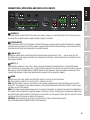 9
9
-
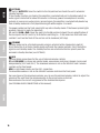 10
10
-
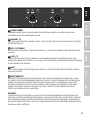 11
11
-
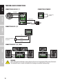 12
12
-
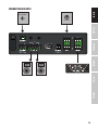 13
13
-
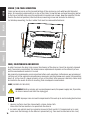 14
14
-
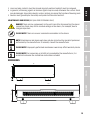 15
15
-
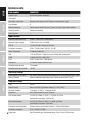 16
16
-
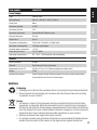 17
17
-
 18
18
-
 19
19
-
 20
20
-
 21
21
-
 22
22
-
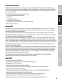 23
23
-
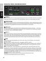 24
24
-
 25
25
-
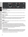 26
26
-
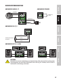 27
27
-
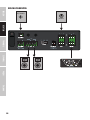 28
28
-
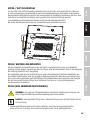 29
29
-
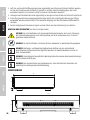 30
30
-
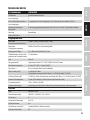 31
31
-
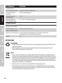 32
32
-
 33
33
-
 34
34
-
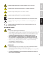 35
35
-
 36
36
-
 37
37
-
 38
38
-
 39
39
-
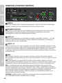 40
40
-
 41
41
-
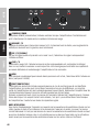 42
42
-
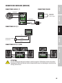 43
43
-
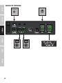 44
44
-
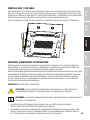 45
45
-
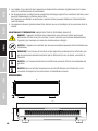 46
46
-
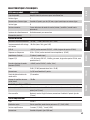 47
47
-
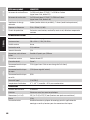 48
48
-
 49
49
-
 50
50
-
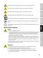 51
51
-
 52
52
-
 53
53
-
 54
54
-
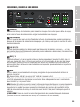 55
55
-
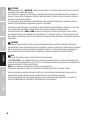 56
56
-
 57
57
-
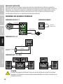 58
58
-
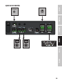 59
59
-
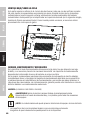 60
60
-
 61
61
-
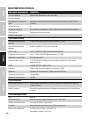 62
62
-
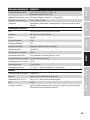 63
63
-
 64
64
-
 65
65
-
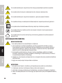 66
66
-
 67
67
-
 68
68
-
 69
69
-
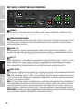 70
70
-
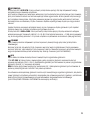 71
71
-
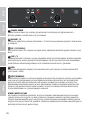 72
72
-
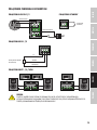 73
73
-
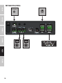 74
74
-
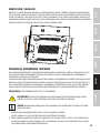 75
75
-
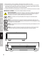 76
76
-
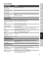 77
77
-
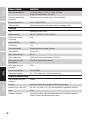 78
78
-
 79
79
-
 80
80
-
 81
81
-
 82
82
-
 83
83
-
 84
84
-
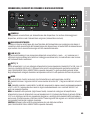 85
85
-
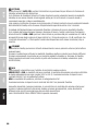 86
86
-
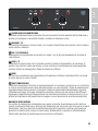 87
87
-
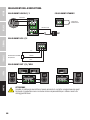 88
88
-
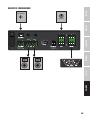 89
89
-
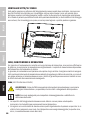 90
90
-
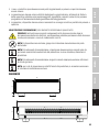 91
91
-
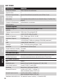 92
92
-
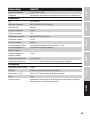 93
93
-
 94
94
-
 95
95
-
 96
96


LD Systems AMP 205 Manual de usuario
- Categoría
- Equipo musical
- Tipo
- Manual de usuario
En otros idiomas
- français: LD Systems AMP 205 Manuel utilisateur
- italiano: LD Systems AMP 205 Manuale utente
- Deutsch: LD Systems AMP 205 Benutzerhandbuch
- polski: LD Systems AMP 205 Instrukcja obsługi
Documentos relacionados
-
LD Systems TR 206 Manual de usuario
-
-
LD Systems IMA30 Installation Amplifier 35W El manual del propietario
-
-
LD Systems DIO 44 Manual de usuario
-
-
-
-
LD Systems Zone 622 Manual de usuario
-