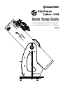
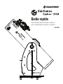
Celestron 22470 Guía del usuario
- Categoría
- Telescopios
- Tipo
- Guía del usuario

Quick Setup Guide
#22470 STARSENSE EXPLORER 8” DOBSONIAN
#22471 STARSENSE EXPLORER 10” DOBSONIAN
ENGLISH

2 I ENGLISH
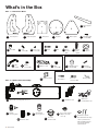
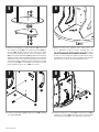
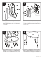
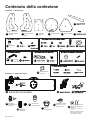
Bottom plateFront panel Top plateLeft side panel
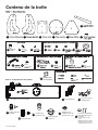
Box 1 – Dobsonian Base
Box 2 – Optical Tube Assembly
Side supports
(x2)
AZIMUTH PIVOT BOLT ASSEMBLY
FEET ASSEMBLY
Rubber bumper
Crescent
wrenches (x2)
Hex keys (x2)
Screwdriver
A1
StarSense dock
P
Optical tube assembly with dust cover
OStarPointer
red dot finderscope
Q
E
Base assembly
screws (x22)
F
Eyepiece rack Rack
screws (x2)
K1 K2 Altitude bearing
cylinders (x4)
L1 Bearing
screws (x4)
L2
M
Base
handle
J1 Handle
screws (x2)
J2
Feet (x3) Bolt Nut Steel
washers
(x2)
H1 H2 H3 Hollow
plastic
cylinder
H4 Teflon
washer
H5
G1 Feet
screws (x3)
G2 Feet screw
covers (x3)
G3
Right side panel
A2 B C D
HANDLE ASSEMBLY EYEPIECE RACK ASSEMBLY ALTITUDE BEARING ASSEMBLY
INCLUDED TOOLS
Altitude
tensioning knob
N1
Cosmetic knob
N2
25mm Omni
Plössl eyepiece
R1
2" focuser
extension tube
S
2"-to-1.25" eyepiece
adapter with 1.25"
cover cap
T
NOTE: For collimating your telescope’s
optics, refer to the full instruction
manual at celestron.com
Collimation cap with
2mm and 2.5mm hex keys*
U
*2.5mm hex key included with 8” Dob only
What’s in the Box

ENGLISH I3
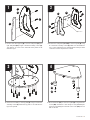
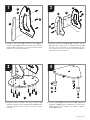
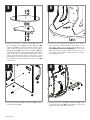
1. Connect the side supports (E) to the left side panel (A1) and
right side panel (A2) using 6 of the base assembly screws (F).
The supports go on the on the same side of the panels as the
Celestron logos.
2. Connect the side panels (A1 & A2) to the front panel (B) using
6 of the base assembly screws (F). Make sure the Celestron
logos on the side panels face outward and the small spot mark
on the face of the front panel faces inward.
A1
E
F
F
F
B
A1
3. Connect the assembly to the top plate (C) using 10 of the base
assembly screws (F). Orient the top plate so the side with the
logo faces upward.
4. Attach the 3 feet (G1) to the bottom plate (D) using the 3 feet
screws (G2). Thread the screws fi rmly into the predrilled pilot
holes. Once installed, press the feet screw covers (G3) onto the
ends of the feet.
F
C
D
G1
G2
G3
A2
A2
4
2
3
1
Spot Mark

4 I ENGLISH
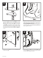
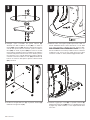
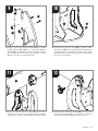
5. Connect the assembly to the bottom plate (D). Place one of the
steel washers (H3) and the plastic cylinder (H4) onto the bolt
(H1). Then, insert the bolt through the central hole in the bottom
plate. Next, place the Tefl on washer (H5) over the plastic
cylinder (H4) now protruding from the bottom plate. Take the
assembled base and lower it onto the bottom plate so that the
plastic cylinder goes through the central hole in the top plate.
Now, place the remaining steel washer (H3) on the end of the
bolt protruding from the top plate. Thread the nut (H2) onto
the bolt.
7. Install the base handle (J1) onto the front panel (B) using the
2 handle screws (J2).
6. Use the two crescent wrenches to tighten the nut onto the bolt.
Hold the head of the bolt stationary with one crescent wrench
while using the other crescent wrench to tighten the nut.
DO NOT OVERTIGHTEN THE NUT! With some force, you
should still be able to move the steel washer underneath the
nut with your fi ngers. If the washer cannot be moved with your
fi ngers, slightly loosen the nut.
8. Install the eyepiece rack (K1) onto the front panel (B) using the
2 rack screws (K2). Note: If you want to remove the rack after it
has been installed, simply pull it upwards.
J1 K1
K21
B
J2
H2
H3
H4
D
H5
H3
H1
6
8
5
7

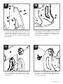
ENGLISH I5
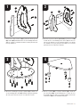
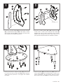
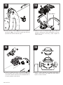
9. Install the altitude bearing cylinders (L1) onto the left and right
side panels (A1 & A2) with the altitude bearing screws (L2).
The bearings go on the interior surfaces of the side panels. The
end of the bearing with no bevel on it should be fl ush to the
surface of the panel.
11. Place the optical tube assembly (O) onto the assembled
Dobsonian base. The side hubs on the tube should sit on the
altitude bearing cylinders on the base.
10. Attach the rubber bumper (M) to the interior surface of the
front panel (B). There is a small spot on the front panel that
indicates where to place the rubber bumper. Remove the
adhesive backing from the bumper and press the bumper fi rmly
onto the spot.
12. Install the altitude tensioning knob (N1) through the slot in the
left side panel (A1) and into the threaded insert in the center of
the side hub on the optical tube assembly.
L1
O
N1 A1
MB
L2
A1
A2
10
12
9
11

6 I ENGLISH
13. Install the cosmetic knob (N2) through the slot in the right side
panel (A2) and into the threaded insert in the center of the side
hub on the optical tube assembly.
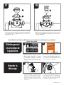
14. Install the StarSense dock (P). First, loosen the 2 thumbscrews
on the StarSense base on the tube. Insert the dock into the
base, and then retighten the thumbscrews.
N2
A2
P
1413
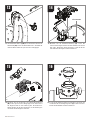
15. Install the StarPointer red dot fi nderscope (Q) onto the
optical tube assembly. First, loosen the thumbscrew on the
fi nderscope holder. Insert the base of the StarPointer into the
holder and tighten the thumbscrew.
16. Loosen the thumbscrews on the end of the focuser and
insert the 2” extension tube (S) into the focuser. Retighten
the thumbscrews.
Q
S
1615
THUMB SCREWS

ENGLISH I7
17. Loosen the thumbscrews on the 2” extension tube (S)
now installed in the focuser and insert the 2”-to-1.25”
eyepiece adapter (T). Retighten the thumbscrews on the
2” extension tube.
Your StarSense Explorer Dobsonian is now fully assembled and ready to be used.
18. Loosen the thumbscrews on the 2”-to-1.25” eyepiece
adapter (T) now installed in the focuser, place the 25mm
Omni Plössl eyepiece (R1) into the adapter, and retighten the
thumbscrews on the adapter.
S
T
T
R1
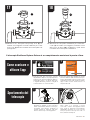
Downloading and
Activating the App
1. Before you take your telescope outside,
download the StarSense Explorer app to your
mobile device. Search for “Celestron StarSense
Explorer” in the Apple App Store or Google Play.
The app is large, so we recommend downloading
it while connected to Wi-Fi.
Download the app from the
before your first observing session
.
or
When prompted, enter the unique unlock code below to
enable telescope control on your device.
2. Once you have downloaded the app, locate the
orange postcard in your telescope box. Launch
the app. When prompted, enter the activation
code on the postcard to activate the app. Your
code will unlock up to 5 devices.
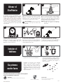
1. The StarSense Dobsonian telescope moves
freely in altitude (up-and-down) and azimuth
(left-to-right). Simply move the tube by
pushing it in the desired direction. You can use
the knob handle at the front of the telescope
for a hand grip.
2. If the altitude motion moves too freely, or the
telescope moves up or down with no force being
applied tighten the altitude tensioning knob.
Conversely, if it takes much force to move the
telescope upwards or downwards, then loosen
the knob.
Moving the
Telescope
22
1817
1
1 2
2

8 I ENGLISH
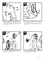
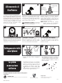
2. CENTER THE TARGET IN THE EYEPIECE
Look through the telescope using the 25mm
eyepiece. Move the telescope until the object you
chose lies in the center of the view. If the image is
blurry, gently turn the focus knobs until it comes
into sharp focus.
NOTE: The image in your telescope may appear
inverted. This is perfectly normal in an
astronomical telescope.
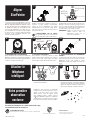
Aligning the
Finderscope
The StarPointer red dot finderscope is one of the
most important parts of your telescope. Although
the StarSense Explorer app will locate and center
objects for you, having the StarPointer properly
aligned will help during alignment of the app to
the telescope. The first time you assemble your
telescope, you need to align the finder to the
telescope’s main optics. It’s best to do this during
the day.*
1. CHOOSE A TARGET
Take the telescope outside during the day and
find an easily recognizable object, such as a
streetlight, car license plate or sign. The object
should be as far away as possible, but at least a
quarter mile away.
*SOLAR WARNING! Never attempt to
view the Sun through any telescope without
a proper solar filter!
4. ADJUST THE FINDERSCOPE
Without moving the telescope, use the two
adjustment knobs to move the red dot until it
appears over the same object you are observing in
the telescope’s 25mm eyepiece.
5. YOUR FINDERSCOPE IS NOW ALIGNED!
It should not require realignment unless it is
bumped or dropped. Now, when you look through
the StarPointer, the red dot will indicate where the
telescope is pointing.
3. LOOK THROUGH FINDERSCOPE
Pull the battery protection tab out of the StarPointer
and turn it on to maximum brightness using the on/
off knob. Look through the StarPointer and locate
the red dot.
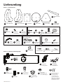
Congratulations! Your telescope is now set
up and you are ready to explore the cosmos.
Take the telescope outside, insert your 25mm
eyepiece, remove the lens cap, insert your
smartphone into the holder, and launch the
StarSense Explorer app. The tutorial in the app
will walk you through the steps to find your first
astronomical target.
1. Remove the large cap covering the mirror on
the front of the StarSense dock.
2. Pull open the spring-loaded slider on the top
of the phone dock and set the phone into
the holder so it is flush with the bottom lip of
the phone holder. Slowly release the slider to
secure the phone in place.
25MM EYEPIECE
FOCUS KNOBS
ON/OFF KNOB
1
3 4
1
5
2
2
Aligning the
StarPointer
Attaching the
Smartphone
Your First
Night Out
For more information on this product, please visit the respective
product page on celestron.com
SOLAR WARNING:
Never attempt to view the Sun through any telescope without a proper solar filter. www.celestron.com/pages/warranty
Need assistance?
Contact Celestron Technical Support by visiting
celestron.com/pages/technical-support
04-22

Guide de confi guration rapide
#22470 STARSENSE EXPLORER 8” DOBSONIAN
#22471 STARSENSE EXPLORER 10” DOBSONIAN
FRANÇAIS

10 I FRANÇAIS
Boîte 2 – Composants du tube optique
COMPOSANTS
Amortisseurs
en caoutchouc
(x2)
(x2)
A1
P Dock StarSense
O Tube optique avec cache-poussière Q
E
F
(x2)
K1 K2
(x4)
L1 Vis
d'orientation
(x4)
L2
M
J1 Vis de
(x2)
J2
(x3)
(x2)
H1 H2 H3
H4
H5
G1 Vis des
(x3)
G2
(x3)
G3
A2 B C D
Bouton de tension
d'altitude
N1
N2 Cache décoratif
R1
S
Adaptateur pour
oculaire de 2" à 1,25"
avec cache de 1,25"
T
U
Chercheur à point
StarPointerred
Oculaire Omni
Plössl de 25 mm
Tube d'extension
de foyer 2"
Capuchon de collimation
avec clefs Allen de 2mm
et 2,5mm*
*Clef Allen de 2,5mm incluse avec Dob 8"
uniquement
REMARQUE: pour effectuer la collimation
des optiques de votre télescope, voyez le
mode d'emploi complet sur celestron.com
(x2)
Contenu de la boîte

FRANÇAIS I11
1. Attachez les supports latéraux (E) au panneaux latéraux gauche
(A1) et droit (A2) à l'aide des 6 des vis d’assemblage de la base
( F). Les supports s’installent du même côté des panneaux que
les logos Celestron.
2. Attachez les panneaux latéraux (A1 et A2) au panneau avant (B)
à l'aide des 6 vis d’assemblage de la base ( F). Assurez-vous
que les logos Celestron sur les panneaux latéraux sont orientés
vers l'extérieur et que le petit point de repère sur la face du
panneau avant est orienté vers l'intérieur.
A1
E
F
F
F
B
A1
3. Attachez l’assemblage à la plaque supérieure (C) à l'aide des 10
vis d’assemblage de la base (F). Orientez la plaque supérieure
de sorte que le côté avec le logo soit orienté vers le haut.
4. Fixez les 3 pieds (G1) à la plaque inférieure (D) à l'aide des
3vis des pieds (G2). Vissez fermement les vis dans les trous
de guidage prépercés. Une fois les pieds installés, enfoncez les
caches de vis (G3) sur les extrémités des pieds.
F
C
D
G1
G2
G3
A2
A2
4
2
3
1
Point de
repère

12 I FRANÇAIS
5. Attachez l’assemblage à la plaque inférieure (D). Placez une
des rondelles en acier (H3) et le cylindre en plastique (H4) sur
le boulon (H1). Insérez ensuite le boulon dans le trou central
de la plaque de inférieure. Ensuite, placez la rondelle en téfl on
(H5) sur le cylindre en plastique (H4) qui dépasse de la plaque
inférieure. Prenez la base assemblée et abaissez-la sur la plaque
inférieure de sorte que le cylindre en plastique passe par le trou
central de la plaque supérieure. Placez maintenant la rondelle
en acier restante (H3) sur l'extrémité du boulon dépassant de la
plaque supérieure. Vissez l'écrou (H2) sur le boulon.
7. Installez la poignée de base (J1) sur le panneau avant (B) à l'aide des
2 vis de poignée (J2).
6. Utilisez les deux clés anglaises pour serrer l'écrou sur
la vis. Maintenez la tête du boulon immobile avec une
clé anglaise tout en utilisant l'autre pour serrer l'écrou.
NE PAS SERRER EXCESSIVEMENT L'ÉCROU! La rondelle
en acier sous l'écrou doit pouvoir être poussée avec les doigts,
en appliquant un peu de force. Si la rondelle ne peut pas être
déplacée avec les doigts, desserrez légèrement l'écrou.
8. Installez le support pour oculaire (K1) sur le panneau avant (B) à
l'aide des 2 vis du rack (K2). Remarque: Si vous souhaitez retirer
le rack après l'avoir installé, il vous suffi t de tirer vers le haut.
J1 K1
K21
B
J2
H2
H3
H4
D
H5
H3
H1
6
8
5
7

FRANÇAIS I13
9. Installez les cylindres d'altitude (L1) sur les panneaux latéraux
gauche et droit (A1 et A2) à l'aide des vis d'orientation d'altitude
(L2). Les supports sont placés sur les surfaces intérieures des
panneaux latéraux. L'extrémité du support sans biseau doit être
au même niveau que la surface du panneau.
11. Placez l'assemblage du tube optique (O) sur la base Dobsonian
assemblée. Les moyeux latéraux du tube doivent reposer sur
les cylindres d'orientation d'altitude de la base.
10. Fixez l'amortisseur en caoutchouc (M) sur la surface intérieure
du panneau avant (B). Un petit point sur le panneau avant
indique où placer l'amortisseur en caoutchouc. Retirez le
support adhésif de l'amortisseur et appuyez fermement sur ce
dernier pour le fi xer fermement sur son emplacement.
12. Installez la molette de tension d'altitude (N1) dans le logement
du panneau latéral gauche (A1) et dans le pas de vis fi leté au
centre du moyeu latéral de l'assemblage du tube optique.
L1
O
N1 A1
MB
L2
A1
A2
10
12
9
11

14 I FRANÇAIS
13. Installez le cache décoratif (N2) par l'ouverture du panneau
latéral droit (A2) et dans le pas de vis fi leté au centre du moyeu
latéral de l'assemblage du tube optique.
14. Installez le dock StarSense (P). Tout d'abord, desserrez les 2
vis à main de la base StarSense sur le tube. Insérez le dock
dans la base, puis resserrez les vis à main.
N2
A2
P
1413
15. Installez le chercheur à point rouge StarPointer (Q) sur
l'assemblage du tube optique. Tout d'abord, desserrez la
vis à main sur le support du chercheur. Insérez la base du
StarPointer dans le support et serrez la vis à main.
16. Desserrez les vis à main sur l'extrémité du foyer et insérez le
tube d'extension de 2" (S) dans le foyer. Resserrez les vis à
main.
Q
S
1615
VIS MAIN

FRANÇAIS I15
17. Desserrez les vis à main du tube d'extension de 2” (S)
maintenant installé dans le porte-oculaire et insérez l'adaptateur
pour oculaire de 2” à 1,25” (T). Resserrez les vis à main sur le
tube d'extension de 2”.
Votre StarSense Explorer Dobsonian est maintenant entièrement assemblé et
prêt à être utilisé.
18. Desserrez les vis à main de l'adaptateur pour oculaire 2” à 1,25”
(T) maintenant installé dans le porte-oculaire, placez l'oculaire
Omni Plössl 25mm (R1) dans l'adaptateur et resserrez les vis
à main de l'adaptateur.
S
T
T
R1
Téléchargement
et activation de
l'application
1. Avant de sortir avec votre télescope, téléchargez
l'application StarSense Explorer sur votre
appareil mobile. Recherchez « Celestron
StarSense Explorer » dans l'App Store d'Apple
ou Google Play. L’application est de grande
taille. Nous vous recommandons donc de la
télécharger lorsque vous êtes connecté à un
réseau Wi-Fi.
Download the app from the
before your first observing session
.
or
When prompted, enter the unique unlock code below to
enable telescope control on your device.
2. Une fois que vous avez téléchargé l'application,
trouvez la carte orange dans la boîte de votre
télescope. Lancez l'application. Lorsque vous y
êtes invité, entrez le code d'activation indiqué
sur la carte pour activer l'application. Votre code
peut déverrouiller jusque 5 appareils.
1. Le télescope Dobsonian de StarSense peut
être orienté librement en altitude (de haut
en bas) et en azimut (de gauche à droite). Il
suffi t d'orienter le tube en le poussant dans
la direction souhaitée. Vous pouvez utiliser la
poignée à l'avant du télescope pour le tenir
mieux en main.
2. Si le mouvement en altitude est trop lâche ou
si le télescope se déplace vers le haut ou vers
le bas sans aucune force, serrez la molette de
tension d'altitude. À l'inverse, si l'orientation du
télescope vers le haut ou vers le bas nécessite
une grande foce, desserrez la molette.
Orienter le
télescope
22
1817
1
1 2
2

16 I FRANÇAIS
2. CENTRER LA CIBLE DANS L'OCULAIRE
Regardez dans l'oculaire de 25mm du télescope.
Orientez le télescope jusqu'à que l'objet choisi se
trouve au centre du champ de vision. Si l’image est
floue, faites doucement tourner la molette de mise
au point jusqu’à ce que l’image soit nette.
REMARQUE : l'image de votre télescope peut
sembler inversée. Cela est
parfaitement normal pour un
télescope astronomique.
Aligner le chercheur
Le chercheur à point rouge StarPointer est l'un des
composants les plus importants de votre télescope.
Bien que l'application StarSense Explorer localise
et centre les objets pour vous, l'alignement correct
de StarPointer aidera lors de l'alignement du
télescope par l'application. La première fois que
vous assemblez votre télescope, vous devez aligner
le chercheur avec le système optique principal du
télescope. Il est recommandé d'effectuer cette
opération pendant la journée*.
1. CHOISIR UNE CIBLE
Installez le télescope à l’extérieur en journée, et
choisissez un objet aisément reconnaissable,
comme un feu de signalisation, une plaque
d’immatriculation ou un panneau. L’objet doit se
situer aussi loin que possible, mais à au moins un
quart de mile de vous.
* AVERTISSEMENT SUR LE SOLEIL!
N’essayez jamais d’observer le soleil à l’aide d’un
télescope sans utiliser un filtre solaire adéquat.
4. AJUSTER LE CHERCHEUR
Sans déplacer le télescope, utilisez les deux
molettes d’ajustement pour déplacer le chercheur
jusqu’à que le point rouge s’aligne sur l’objet
observé dans l’oculaire de 25mm du télescope.
5. VOTRE CHERCHEUR EST MAINTENANT
ALIGNÉ !
Il n'aura pas besoin d'être aligné de nouveau tant
qu'il n'aura pas subi un choc ou qu'il sera tombé.
Maintenant, lorsque vous regardez à travers
StarPointer, le point rouge indique où le télescope
pointe.
3. REGARDER DANS LE CHERCHEUR
Retirez la languette de protection de la batterie du
StarPointer et allumez-le à la luminosité maximale à
l'aide de la molette marche/arrêt. Regardez dans le
chercheur et localisez le point rouge.
Félicitations! Votre télescope est maintenant
configuré et vous êtes prêt à explorer le cosmos.
Sortez le télescope, insérez votre oculaire
25mm, retirez le cache de l'objectif, insérez
votre smartphone dans le support et lancez
l'application StarSense Explorer. Le didacticiel
de l'application vous guide à travers les étapes
pour trouver votre première cible astronomique.
1. Retirez le grand capuchon recouvrant le miroir à
l'avant du dock StarSense.
2. Ouvrez la glissière à ressort située sur le dessus
du support de téléphone et installez le téléphone
pour qu’il soit à niveau sur le rebord du bas du
support de téléphone. Relâchez la glissière en
douceur pour maintenir le téléphone en place.
OCULAIRE DE 25MM:
MOLETTES DE
MISE AU POINT
MOLETTE
MARCHE/ARRÊT
1
3 4
1
5
2
2
Aligner
StarPointer
Attacher le
téléphone
intelligent
Votre première
observation
nocturne
Pour obtenir plus d'informations sur le produit, veuillez visiter la page
correspondante du produit sur celestron.com
AVERTISSEMENT SUR LE SOLEIL:
N’essayez jamais d’observer le soleil à l’aide d’un télescope sans utiliser un filtre solaire adéquat. Besoin d'assistance?
Contactez le support technique de Celestron
celestron.com/pages/technical-support
04-22
www.celestron.com/pages/warranty

Kurzanleitung zur Einrichtung
22470 STARSENSE EXPLORER 8” DOBSON
22471 STARSENSE EXPLORER 10” DOBSON
DEUTSCH

18 I DEUTSCH
Untere PlatteVorderseite Obere PlatteLinke Seitenwand
Karton 1 – Dobson-Sockel
Karton 2 – Optische Tubus-Baugruppe
Seitliche Stützen
(x2)
MONTAGEELEMENTE DES AZIMUT-SCHWENKBOLZENS
MONTAGEELEMENTE DER FÜßE
Gummipuffer
Rollgabelschlüssel
(x2)
Sechskantschlüssel
(x2)
Schraubendreher
A1
P StarSense-
Dockingstation
O Optische Tubus-Baugruppe mit Staubschutzabdeckung StarPointer-
Leuchtpunkt-
Sucherfernrohr
Q
E
Schrauben des
Sockels (x22)
F
Okularhalter Schrauben des
Halters (x2)
K1 K2 Höhenlagerzylinder
(x4)
L1 Schrauben des
Lagers (x4)
L2
M
Sockel-
Handgriff
J1 Handgriffsch-
rauben (x2)
J2
Füße (x3) Bolzen Mutter Stahl-Unte-
rlegscheiben
(x2)
H1 H2 H3 Kunststoff-
Hohlzylinder
H4 Teflon-
Unterlegscheibe
H5
G1 Schrauben
für Füße (x3)
G2 Schraubena-
bdeckungen
für Füße (x3)
G3
A2 Rechte Seitenwand B C D
MONTAGEELEMENTE DES HANDGRIFFS MONTAGEELEMENTE DES
OKULARHALTERS
MONTAGEELEMENTE DES HÖHENLAGERS
MITGELIEFERTE WERKZEUGE
Höhen-
Widerstandsknopf
N1
N2 Zierknopf
R1
S
2“-auf-1,25“-
Okularadapter mit
1,25“-Abdeckkappe
TU
25-mm-Omni-
Plössl-Okular
2“ Fokussierer-
Verlängerungstu
bus
Kollimationskappe mit
2-mm- und 2,5-mm
Sechskantschlüssel*
*2,5-mm-Sechskantschlüssel nur bei
20,3-cm-Dob im Lieferumfang enthalten
HINWEIS: Informationen zur Kollimation Ihrer
Teleskopoptik finden Sie in der vollständigen
Bedienungsanleitung unter celestron.com
Lieferumfang

DEUTSCH I19
1. Verbinden Sie die seitlichen Stützen (E) mit der linken (A1) und
rechten (A2) Seitenwand unter Verwendung von 6 Schrauben
des Sockels (F). Die Stützen werden auf der gleichen Seite
der Seitenwände angebracht, auf der sich auch die Celestron-
Logos befi nden.
2. Verbinden Sie die Seitenwände (A1 und A2) mit der Vorderseite
(B) unter Verwendung von 6 Schrauben des Sockels (F). Achten
Sie darauf, dass die Celestron-Logos auf den Seitenwänden
nach außen und die kleine Punktmarkierung auf der Vorderseite
nach innen zeigen.
A1
E
F
F
F
B
A1
3. Verbinden Sie die Baugruppe mit der oberen Platte (C) unter
Verwendung von 10 Schrauben des Sockels (F). Richten Sie die
obere Platte so aus, dass die Seite mit dem Logo nach oben zeigt.
4. Befestigen Sie die 3 Füße (G1) mit den 3 Schrauben für die Füße
(G2) an der unteren Platte (D). Ziehen Sie die Schrauben in den
vorgebohrten Löchern fest. Drücken Sie nach der Montage die
Schraubenabdeckungen der Füße (G3) auf die Fußenden.
F
C
D
G1
G2
G3
A2
A2
4
2
3
1
Punktmarkierung

20 I DEUTSCH
5. Verbinden Sie die Baugruppe mit der unteren Platte (D).
Stecken Sie eine der Stahl-Unterlegscheiben (H3) und den
Kunststoffzylinder (H4) auf den Bolzen (H1). Führen Sie dann
den Bolzen durch das mittlere Loch in der unteren Platte.
Platzieren Sie als nächstes die Tefl on-Unterlegscheibe (H5)
über dem Kunststoffzylinder (H4), der nun aus der unteren Platte
herausragt. Nehmen Sie den zusammengebauten Sockel und
setzen Sie ihn so auf die untere Platte, dass der Kunststoffzylinder
durch das mittlere Loch in der oberen Platte hindurchgeht.
Platzieren Sie nun die verbleibende Stahl-Unterlegscheibe (H3)
auf dem Ende des Bolzens, die aus der oberen Platte herausragt.
Ziehen Sie die Mutter (H2) auf dem Bolzen fest.
7. Montieren Sie den Sockel-Handgriff (J1) an der Vorderseite (B)
unter Verwendung der 2 Schrauben für den Handgriff (J2).
6. Ziehen Sie die Mutter mit beiden Schraubenschlüsseln
auf dem Bolzen fest. Halten Sie den Kopf des Bolzens
mit einem der Schraubenschlüssel fest, während Sie die
Mutter mit dem anderen Schraubenschlüssel anziehen.
ZIEHEN SIE DIE MUTTER NICHT ZU FEST AN! Sie sollten
die Stahl-Unterlegscheibe unterhalb der Mutter mit etwas
Kraftaufwand noch mit den Fingern bewegen können. Lässt sich
die Unterlegscheibe nicht mit den Fingern bewegen, lockern Sie
die Mutter etwas.
8. Montieren Sie den Okularhalter (K1) unter Verwendung der 2
Schrauben für den Halter (K2) auf der Vorderseite (B). Hinweis:
Wenn Sie den Halter nach der Montage entfernen möchten,
ziehen Sie ihn einfach nach oben.
J1 K1
K21
B
J2
H2
H3
H4
D
H5
H3
H1
6
8
5
7

DEUTSCH I21
9. Montieren Sie die Höhenlagerzylinder (L1) unter Verwendung
der Höhenlagerschrauben (L2) an den linken und rechten
Seitenwand (A1 und A2). Die Lager werden an den
Innenfl ächen der Seitenwände angebracht. Das Ende des
Lagers ohne Abschrägung muss bündig mit der Oberfl äche der
Platte abschließen.
11. Platzieren Sie die optische Tubus-Baugruppe (O) auf
dem zusammengebaute Dobson-Sockel. Die seitlichen
Drehscheiben des Tubus müssen auf den Höhenlagerzylindern
des Sockels ruhen.
10. Bringen Sie den Gummipuffer (M) an der Innenseite der
Vorderseite (B) an. Auf der Vorderseite befi ndet sich ein kleiner
Punkt, der anzeigt, wo der Gummipuffer angebracht werden
muss. Entfernen Sie die Klebefolie vom Gummipuffer und
drücken Sie ihn fest auf den Punkt.
12. Stecken Sie den Höhen-Widerstandsknopf (N1) durch
den Schlitz in der linken Seitenwand (A1) und in den
Gewindeeinsatz in der Mitte der seitlichen Drehscheibe der
optischen Tubus-Baugruppe.
L1
O
N1 A1
MB
L2
A1
A2
10
12
9
11

22 I DEUTSCH
13. Stecken Sie den Zierknopf (N2) durch den Schlitz in der rechten
Seitenwand (A2) und in den Gewindeeinsatz in der Mitte der
seitlichen Drehscheibe der optischen Tubus-Baugruppe.
14. Montieren Sie die StarSense-Halterung (P). Lösen Sie
zunächst die 2 Flügelschrauben an dem StarSense-Sockel auf
dem Tubus. Setzen Sie die Dockingstation in den Sockel ein
und ziehen Sie die Flügelschrauben wieder fest.
N2
A2
P
1413
15. Montieren Sie das StarPointer Leuchtpunkt-Sucherfernrohr
(Q) auf der optischen Tubus-Baugruppe. Lösen Sie zunächst
die Flügelschraube an der Halterung des Sucherfernrohrs.
Setzen Sie den Sockel des StarPointers in die Halterung ein
und ziehen Sie die Flügelschraube fest.
16. Lösen Sie die Flügelschrauben am Ende des Fokussierer und
stecken Sie den 2“-Verlängerungstubus (S) in den Fokussierer.
Ziehen Sie die Rändelschrauben wieder fest.
Q
S
1615
FLÜGELSCHRAUBEN

DEUTSCH I23
17. Lösen Sie die Flügelschrauben am 2"-Verlängerungstubus (S),
der jetzt im Fokussierer installiert ist und setzen Sie den 2“-auf-
1,25“-Okularadapter (T) ein. Ziehen Sie die Flügelschrauben
am 2"-Verlängerungstubus wieder fest.
Ihr StarSense Explorer Dobson ist nun vollständig zusammengebaut und einsatzbereit.
18. Lösen Sie die Flügelschrauben am 2“-auf-1,25“-Okularadapter
(T), der jetzt im Fokussierer installiert ist, setzen Sie das 25-mm-
Omni-Plössl-Okular (R1) in den Adapter ein und ziehen Sie die
Flügelschrauben am Adapter wieder fest.
S
T
T
R1
App herunterladen
und aktivieren
1. Laden Sie die StarSense Explorer-App auf Ihr
Mobilgerät herunter, bevor Sie Ihr Teleskop mit
nach draußen nehmen. Suchen Sie im Apple
App Store oder bei Google Play nach „Celestron
StarSense Explorer“. Die App ist groß. Daher
empfehlen wir, sie über eine bestehende WLAN-
Verbindung herunterzuladen.
Download the app from the
before your first observing session
.
or
When prompted, enter the unique unlock code below to
enable telescope control on your device.
2. Nehmen Sie nach dem Herunterladen der
App die orangefarbene Postkarte aus Ihrer
Teleskopverpackung. Starten Sie die App. Wenn
Sie dazu aufgefordert werden, geben Sie den
Aktivierungscode auf der Postkarte ein, um die
App zu aktivieren. Ihr Code kann bis zu 5 Geräte
entsperren.
1. Das StarSense Dobson-Teleskop kann in der
Höhe (auf und ab) und im Azimut (von links
nach rechts) frei bewegt werden. Bewegen
Sie den Tubus einfach, indem Sie ihn in die
gewünschte Richtung drücken. Sie können den
Knopfgriff an der Vorderseite des Teleskops als
Handgriff verwenden.
2. Wenn die Höhenbewegung zu leichtgängig ist
oder das Teleskop sich ohne Kraftaufwand nach
oben oder unten bewegen lässt, ziehen Sie den
Höhen-Widerstandsknopf an. Umgekehrt, wenn
es viel Kraft braucht, um das Teleskop nach oben
oder unten zu bewegen, dann lösen Sie den
Knopf etwas.
Bewegen des
Teleskops
22
1817
1
1 2
2

24 I DEUTSCH
2. ZENTRIEREN SIE DAS ZIEL IM OKULAR
Schauen Sie mit dem 25-mm-Okular durch das
Teleskop. Schwenken Sie das Teleskop, bis das
ausgewählte Objekt im Zentrum des Sichtfelds
liegt. Ist das Bild unscharf, drehen Sie langsam am
Fokussierknopf, bis das Bild scharf gestellt ist.
HINWEIS: Das Bild in Ihrem Teleskop erscheint
möglicherweise invertiert. Das ist bei
einem Astronomie-Teleskop völlig
normal.
Ausrichten des
Sucherfernrohrs
Das StarPointer Leuchtpunkt-Sucherfernrohr
ist eines der wichtigsten Teile Ihres Teleskops.
Obwohl die StarSense Explorer-App für Sie
Objekte ausfindig machen und zentrieren
kann, hilft eine korrekte Ausrichtung des
StarPointers bei der Abstimmung der App mit
dem Teleskop. Wenn Sie Ihr Teleskop zum
ersten Mal zusammenbauen, müssen Sie das
Sucherfernrohr auf die Hauptoptik des Teleskops
ausrichten. Dies tun Sie am besten tagsüber.*
1. WÄHLEN SIE EIN ZIEL
Nehmen Sie das Teleskop tagsüber mit nach
draußen und suchen Sie ein leicht erkennbares
Objekt wie z. B. eine Straßenlaterne, ein Kfz-
Kennzeichen oder ein Schild. Das Objekt sollte
400 Meter oder weiter entfernt sein.
*SONNENSTRAHLEN-WARNHINWEIS!
Niemals ohne einen vorschriftsmäßigen
Sonnenfilter durch ein Teleskop in die Sonne
schauen!
4. SUCHERFERNROHR EINSTELLEN
Verschieben Sie den roten Punkt mit den beiden
Einstellknöpfen, ohne das Teleskop zu bewegen,
bis er über demselben Objekt erscheint, das Sie im
25-mm-Okular des Teleskops beobachten.
5. IHR SUCHERFERNROHR IST JETZT
AUSGERICHTET!
Es ist keine Neuausrichtung erforderlich, es sei
denn, es wurde einem Stoß ausgesetzt oder fiel um.
Wenn Sie nun durch den StarPointer schauen, zeigt
der rote Punkt an, wohin das Teleskop zeigt.
3. SCHAUEN SIE DURCH DAS
SUCHERFERNROHR
Ziehen Sie den Schutzstreifen für die Batterie aus
dem StarPointer heraus und stellen Sie es mit
dem Ein-/Aus-Knopf auf maximale Helligkeit ein.
Schauen Sie durch das StarPointer und suchen Sie
den roten Punkt.
Herzlichen Glückwunsch! Nun ist Ihr Teleskop
vollständig zusammengebaut und Sie sind
bereit, den Kosmos zu erforschen. Nehmen
Sie das Teleskop nach draußen, setzen Sie
Ihr 25-mm-Okular ein, entfernen Sie den
Objektivdeckel, setzen Sie Ihr Smartphone in
die Halterung ein und starten Sie die StarSense
Explorer-App. Das Tutorial der App führt Sie
durch die Schritte zum Auffinden Ihres ersten
astronomischen Ziels.
1. Entfernen Sie die große Kappe, die den
Spiegel auf der Vorderseite der StarSense-
Dockingstation abdeckt.
2. Öffnen Sie den federgespannten Schieber oben
am Telefondock durch Ziehen und setzen Sie das
Telefon so in die Halterung ein, dass es bündig
mit der unteren Lippe der Telefonhalterung
abschließt. Lassen Sie den Schieber langsam
los, um das Telefon zu sichern.
25-MM-OKULAR
FOKUSSIERKNÖPFE
EIN-/AUSSCHALTKNOPF
1
3 4
1
5
2
2
Ausrichtung des
StarPointer
Anbringen des
Smartphones
Ihre erste
Nacht im Freien
Für weitere Informationen zu diesem Produkt besuchen Sie bitte die
entsprechende Produktseite auf celestron.com
SONNENSTRAHLEN-WARNHINWEIS:
Versuchen Sie niemals, ohne einen geeigneten Sonnenfilter die Sonne durch ein Teleskop
zu beobachten.
Brauchen Sie Unterstützung?
Wenden Sie sich an die technische Unterstützung von Celestron durch Aufrufen
von celestron.com/pages/technical-support
04-22
www.celestron.com/pages/warranty

Guida rapida
22470 STARSENSE EXPLORER 8” DOBSON
22471 STARSENSE EXPLORER 10” DOBSON
ITALIANO

26 I ITALIANO
Piastra inferiorePannello
anteriore
Piastra superiorePannello laterale
sinistro
Confezione 1 – Base Dobson
Confezione 2 - Gruppo tubo ottico
(x2)
M
M
Ammortizzatore
in gomma
regolabili (x2)(x2)
A1
P
OQ
E
base (x22)
F
griglia (x2)
K1 K2
altitudine (x4)
L1
(x4)
L2
M
Maniglia
della base
J1
(x2)
J2
Piedini (x3)
in acciaio
(x2)
H1 H2 H3
plastica cavo
H4
teflon
H5
G1
piedini (x3)
G2 copriviti
G3
A2 Pannello laterale
destro
B C D
M M M
A
Manopola
tensionamento
altitudine
N1
N2 Manopola
decorativa
R1
S
Adattatore oculare
da 2” a 1,25" con
tappo da 1,25"
T
U
Oculare Omni
Plössl da 25 mm
Prolunga
focheggiatore 2"
Tappo collimazione con
chiavi esagonali 2mm e
2,5mm*
*chiave esagonale da 2,5mm in dotazione solo
con Dob 8"
NOTA: per la collimazione delle ottiche del
telescopio, consultare il manuale di
istruzioni completo su celestron.com
Contenuto della confezione

ITALIANO I27
1. Collegare i supporti laterali (E) al pannello di sinistra (A1) e al
pannello di destra (A2) utilizzando 6 delle viti per il montaggio
della base (F). I supporti devono essere posizionati sul lato dei
pannelli in cui si trova il logo Celestron.
2. Collegare i pannelli laterali (A1 & A2) al pannello anteriore
(B) utilizzando 6 delle viti per il montaggio della base (F).
Assicurarsi che il logo Celestron sui pannelli laterali sia rivolto
verso l’esterno e che il piccolo segno sulla faccia del pannello
anteriore sia rivolto verso l’interno.
A1
E
F
F
F
B
A1
3. Collegare quanto assemblato alla piastra superiore (C)
utilizzando 10 delle viti per il montaggio della base (F). Orientare
la piastra superiore in modo che il lato con il logo sia rivolto
verso l’alto.
4. Fissare i 3 piedini (G1) alla piastra inferiore (D) utilizzando le
3 apposite viti (G2). Avvitare saldamente le viti nei fori pilota
predisposti. Una volta installate le viti, premere i cappucci
coprivite (G3) sulle viti.
F
C
D
G1
G2
G3
A2
A2
4
2
3
1
Segno

28 I ITALIANO
5. Collegare quanto assemblato alla piastra inferiore (D).
Sistemare una delle rondelle in acciaio (H3) e il cilindro in
plastica (H4) sul bullone (H1). Quindi, inserire il bullone nel foro
centrale della piastra inferiore. Sistemare quindi la rondella in
tefl on (H5) sul cilindro in plastica (H4) che fuoriesce ora dalla
piastra inferiore. Prendere la base assemblata in precedenza e
sistemarla sulla piastra inferiore in modo che il cilindro in plastica
passi attraverso il foro centrale della piastra superiore. Quindi,
sistemare la restante rondella in acciaio (H3) all’estremità del
bullone che fuoriesce dalla piastra superiore. Serrare il dado
(H2) sul bullone.
7. Installare la maniglia della base (J1) sul pannello anteriore (B)
utilizzando le 2 apposite viti (J2).
6. Utilizzare le due chiavi inglesi regolabili per serrare il dado sul
bullone. Mantenere ferma la testa del bullone con una delle
chiavi inglesi regolabili e utilizzare l’altra per serrare il dado.
NON SERRARE ECCESSIVAMENTE IL DADO. Con un po’
di forza dovrebbe ancora essere possibile muovere con le dita la
rondella in acciaio che si trova sotto il dado. Se non è possibile
muovere la rondella con le dita, allentare leggermente il dado.
8. Installare la griglia per oculari (K1) sul pannello anteriore (B)
utilizzando le 2 apposite viti (K2). Nota: se si desidera rimuovere
la griglia dopo averla installata, occorre semplicemente tirarla
verso l’alto.
J1 K1
K21
B
J2
H2
H3
H4
D
H5
H3
H1
6
8
5
7

ITALIANO I29
9. Installare i cuscinetti cilindrici dell’altitudine (L1) sui pannelli
laterali sinistro e destro (A1 & A2) utilizzando le apposite viti
(L2). I cuscinetti devono essere montati sulla superfi cie interna
dei pannelli laterali. L’estremità del cuscinetto senza smussatura
deve essere a contatto con la superfi cie del pannello.
11. Sistemare il gruppo del tubo ottico (O) sulla base Dobson
assemblata. I mozzi laterali del tubo devono poggiare sui
cuscinetti cilindrici dell’altitudine sulla base.
10. Fissare l’ammortizzatore in gomma (M) alla superfi cie interna
del pannello anteriore (B). È presente un piccolo segno
sul pannello anteriore che indica il luogo in cui sistemare
l’ammortizzatore in gomma. Rimuovere il rivestimento adesivo
dall’ammortizzatore e premere saldamente quest’ultimo sul
segno.
12. Inserire la manopola di tensionamento dell’altitudine (N1) nella
fessura del pannello laterale sinistro (A1) e nell’inserto fi lettato
al centro del mozzo laterale sul gruppo del tubo ottico.
L1
O
N1 A1
MB
L2
A1
A2
10
12
9
11

30 I ITALIANO
13. Inserire la manopola decorativa (N2) nella fessura del pannello
laterale destro (A2) e nell’inserto fi lettato al centro del mozzo
laterale sul gruppo del tubo ottico.
14. Installare l’aggancio StarSense (P). Innanzitutto, allentare le
2 viti a testa piatta sulla base StarSense sul tubo. Inserire
l’aggancio sulla base, quindi serrare nuovamente le viti.
N2
A2
P
1413
15. Installare il cercatore con puntino rosso StarPointer (Q) nel
gruppo del tubo ottico. Innanzitutto allentare la vite a testa
piatta sul supporto del cercatore. Inserire la base dello
StarPointer nel supporto e serrare la vite.
16. Allentare le viti a testa piatta all’estremità del focheggiatore
e inserire la prolunga da 2” (S) nel focheggiatore. Serrare
nuovamente le viti a testa piatta.
Q
S
1615
VITI A TESTA PIATTA

ITALIANO I31
17. Allentare le viti a testa piatta sulla prolunga da 2” (S) ora
installata sul focheggiatore e inserire l’adattatore per oculare
da 2” a 1,25” (T). Serrare nuovamente le viti a testa piatta sulla
prolunga da 2”.
Il telescopio StarSense Explorer Dobson è ora completamente montato ed è pronto all’uso.
18. Allentare le viti a testa piatta sull’adattatore per oculare da 2”
a 1,25” (T) ora installato sul focheggiatore, sistemare l’oculare
Omni Plössl da 25mm (R1) sull’adattatore, quindi serrare
nuovamente le viti a testa piatta sull’adattatore.
S
T
T
R1
Come scaricare e
attivare l'app
1. Prima di portare fuori il telescopio, scaricare
l'app StarSense Explorer sul proprio dispositivo
mobile. Cercare “Celestron StarSense Explorer”
nell'App Store Apple o su Google Play. L'app
è di grandi dimensioni, pertanto si consiglia di
scaricarla mentre si è connessi al Wi-Fi.
Download the app from the
before your first observing session
.
or
When prompted, enter the unique unlock code below to
enable telescope control on your device.
2. Una volta scaricata l'app, individuare la cartolina
arancione all'interno della scatola del telescopio.
Avviare l’app. Quando richiesto, inserire il codice
di attivazione presente sulla cartolina per attivare
l'app. Il codice consente di sbloccare fi no a 5
dispositivi alla volta.
1. Il telescopio StarSense Dobson si sposta
liberamente in altitudine (su-giù) e sulla linea
azimut (sinistra-destra). Muovere il telescopio
spostandolo nella direzione desiderata. È
possibile utilizzare la manopola sulla parte
anteriore del telescopio come impugnatura.
2. Se il movimento in altitudine è eccessivamente
libero, oppure se il telescopio si sposta
verso l’alto e il basso senza applicare alcuna
forza, serrare la manopola di tensionamento
dell’altitudine. Al contrario, se occorre eccessiva
forza per spostare il telescopio verso l’alto o il
basso, allentare la manopola.
Spostamento del
telescopio
22
1817
1
1 2
2

32 I ITALIANO
2. CENTRARE L'OGGETTO NELL'OCULARE
Guardare attraverso il telescopio utilizzando
l'oculare da 25mm. Muovere il telescopio fino a
quando l'oggetto prescelto si trova al centro del
campo visivo. Se l'immagine è sfocata, ruotare con
delicatezza le manopole di messa a fuoco fino a
quando l'immagine non è nitida.
NOTA: L'immagine del telescopio potrebbe
apparire capovolta. Ciò è perfettamente
normale per un telescopio astronomico.
Allineamento del
cercatore
Il cercatore con puntino rosso StarPointer è uno
dei componenti più importanti del telescopio.
Sebbene l’app StarSense Explorer individui e centri
gli oggetti autonomamente, il corretto allineamento
dello StarPointer aiuta l’allineamento dell’app con il
telescopio. Al primo assemblaggio del telescopio
è necessario allineare il cercatore con le ottiche
principali del telescopio. È preferibile eseguire
questa operazione durante il giorno*.
1. SCEGLIERE UN OGGETTO DA OSSERVARE
Portare il telescopio all'esterno durante il giorno
e individuare un oggetto facilmente riconoscibile,
come ad esempio un semaforo, la targa di un'auto
o un cartello. L'oggetto dovrebbe trovarsi il più
lontano possibile, minimo a 400 metri.
*AVVERTENZA SOLARE! Non tentare mai
di osservare il Sole attraverso un telescopio
senza un filtro solare adeguato.
4. REGOLARE IL CERCATORE
Senza spostare il telescopio, utilizzare le due
manopole di regolazione per spostare il puntino
rosso fino a quando appare sullo stesso oggetto
che si sta osservando nell'oculare da 25mm.
5. IL CERCATORE È ORA ALLINEATO!
Non occorre effettuare un nuovo allineamento salvo
colpi o cadute. Ora, quando si osserva attraverso
lo StarPointer, il puntino rosso indica dove sta
puntando il telescopio.
3. OSSERVARE ATTRAVERSO IL CERCATORE
Estrarre la linguetta di protezione della batteria dallo
StarPointer e accenderlo alla luminosità massima
utilizzando la manopola on/off. Osservare attraverso
lo StarPointer e localizzare il puntino rosso.
Congratulazioni! Il telescopio è ora configurato
e tutto è pronto per esplorare il cosmo. Portare
all'esterno il telescopio, inserire l'oculare da
25 mm, rimuovere il tappo dalla lente, inserire
lo smartphone nel supporto e avviare l'app
StarSense Explorer. Il tutorial dell'app guida
l'utente attraverso i vari passaggi necessari per
localizzare il primo oggetto astronomico.
1. Rimuovere il coperchio grande che copre lo
specchio nella parte anteriore dell'aggancio
StarSense.
2. Tirare per aprire il binario caricato a molla in
cima all'aggancio per telefono e sistemare il
telefono nel supporto in modo che sia a contatto
con il lembo inferiore del supporto del telefono.
Rilasciare lentamente il binario per fissare il
telefono in posizione.
OCULARE 25 MM
MANOPOLE DI
MESSA A FUOCO
MANOPOLA ON/OFF
1
3 4
1
5
2
2
Allineamento di
StarPointer
Collegamento dello
smartphone
La prima
osservazione
notturna
Per maggiori informazioni sul prodotto, visitare la relativa pagina su
celestron.com
AVVERTENZA SOLARE:
Non tentare mai di osservare il Sole attraverso un telescopio senza un filtro solare adeguato.
www.celestron.com/pages/warranty
Bisogno di aiuto?
Contattare il supporto tecnico Celestron visitando
celestron.com/pages/technical-support
04-22

Guía de instalación rápida
#22470 STARSENSE EXPLORER 8" DOBSONIANO
#22471 STARSENSE EXPLORER 10" DOBSONIANO
ESPAÑOL

34 I ESPAÑOL
Plancha inferiorPanel frontal Plancha superiorPanel de lado izquierdo
Caja 1 - Base dobsoniana
Caja 2 - Estructura del tubo óptico
Soportes laterales
(x2)
MONTAJE DE PERNO DE PIVOTAJE AZIMUT
MONTAJE DE PATAS
Parachoques de
caucho
Llaves inglesas
(x2)
Llaves
hexagonales
(x2)
Destornillador
A1
PConector de
StarSense
OEstructura de tubo óptico con cubierta para polvo Localizador de punto
rojo StarPointer
Q
E
Tornillos de estructura
de base (x22)
F
Soporte de
oculares
Tornillos del
soporte (x2)
K1 K2 Cilindros del
rodamiento de altitud
(x4)
L1 Tornillos del
rodamiento
(x4)
L2
M
Mango
de la base
J1 Tornillos del
mango (x2)
J2
Patas (x3) Perno Rosca Arandelas
de acero
(x2)
H1 H2 H3 Cilindro de
plástico
hueco
H4 Arandela de
teflón
H5
G1 Tornillos
de patas (x3)
G2 Cubiertas de
tornillos de
patas (x3)
G3
A2 Panel de lado
derecho
B C D
MONTAJE DEL MANGO MONTAJE DEL SOPORTE DE OCULARES MONTAJE DEL RODAMIENTO DE ALTITUD
HERRAMIENTAS INCLUIDAS
Mando de tensión
de altitud
N1
N2 Mando cosmético
R1
S
Adaptador de ocular de
2" a 1,25" con tapón de
cubierta de 1,25"
T
U
Ocular Omni
Plössi de 25mm
Tubo extensor de
enfoque de 2"
Tapa de colimado con
llaves hexagonales de
2mm y 2,5mm*
*Llave hexagonal de 2,5mm incluida
solamente con Dob de 8” Dob
NOTA: Para colimar la óptica de su
telescopio, consulte el manual de
instrucciones completo en celestron.com
Contenido de la caja

ESPAÑOL I35
1. Conecte los soportes laterales (E) al panel del lado izquierdo
(A1) y el panel del lado derecho (A2) usando 6 de los tornillos
de la estructura de la base (F). Los soportes van al mismo lado
de los paneles que el logotipo de Celestron.
2. Conecte los paneles laterales (A1 y A2) al panel frontal (B)
usando 6 de los tornillos de la estructura de la base (F).
Asegúrese de que los logotipos de Celestron de los paneles
laterales estén orientados hacia fuera y que la marca con el
punto pequeño del panel frontal esté orientada hacia dentro.
A1
E
F
F
F
B
A1
3. Conecte la estructura a la plancha superior (C) usando 10 de
los tornillos de la estructura de la base (F). Oriente la plancha
superior de forma que el lado con el logotipo esté orientado
hacia arriba.
4. Instale las 3 patas (G1) a la plancha inferior (D) usando los 3
tornillos de patas (G2). Enrosque fi rmemente los tornillos en los
agujeros pretaladrados. Una vez instalado, presione las tapas
de los tornillos de las patas (G3) en los extremos de las patas.
F
C
D
G1
G2
G3
A2
A2
4
2
3
1
Marca de punto

36 I ESPAÑOL
5. Conecte la estructura a la plancha inferior (D). Ponga una
de las arandelas de acero (H3) y el cilindro de plástico (H4)
sobre el perno (H1). A continuación, introduzca el perno por el
agujero central de la plancha inferior. A continuación, ponga la
arandela de tefl ón (H5) sobre el cilindro de plástico (H4) que
sobresale de la plancha. Tome la base montada y bájela sobre la
plancha inferior de forma que el cilindro de plástico pase por el
agujero central de la plancha superior. A continuación, coloque
la arandela de acero restante (H3) sobre el extremo del perno
que sobresale de la plancha superior. Enrosque la rosca (H2)
sobre el perno.
7. Instale el mango de la base (J1) en el panel frontal (B) usando los
2 tornillos del mango (J2).
6. Use las dos llaves inglesas para apretar la rosca sobre el
perno. Aguante el cabezal del perno estacionario con una
llave inglesa mientras usa la otra llave para apretar la rosca.
¡NO APRIETE LA ROSCA EN EXCESO! Con cierta fuerza
debería ser capaz de mover la arandela de acero bajo la rosca
con los dedos. Si la arandela no puede moverse con los dedos,
afl oje ligeramente la rosca.
8. Instale el soporte del ocular (K1) en el panel frontal (B) usando
los 2 tornillos del soporte (K2). Nota: Si desea sacar el soporte
después de instalarlo, tire de él hacia arriba.
J1 K1
K21
B
J2
H2
H3
H4
D
H5
H3
H1
6
8
5
7

ESPAÑOL I37
9. Instale los cilindros del rodamiento de altitud (L1) en los paneles
izquierdo y derecho (A1 y A2) con los tornillos del rodamiento
de altitud (L2). Los rodamientos van en las superfi cies interiores
de los paneles laterales. El extremo del rodamiento sin bisel
debe estar ajustado a la superfi cie del panel.
11. Ponga la estructura del tubo óptico (O) sobre la base
dobsoniana montada. Los bujes laterales del tubo deberían
asentarse en los cilindros del rodamiento de altitud en la base.
10. Instale el parachoques de caucho (M) a la superfi cie interior
del panel frontal (B). Hay un pequeño punto en el panel frontal
que indica dónde colocar el parachoques de caucho. Saque
la tira del adhesivo del parachoques y presione fi rmemente el
parachoques sobre el punto.
12. Instale el mando de tensado de altitud (N1) por la ranura del
panel del lado izquierdo (A1) y en el accesorio estriado del
centro del buje lateral en la estructura del tubo óptico.
L1
O
N1 A1
MB
L2
A1
A2
10
12
9
11

38 I ESPAÑOL
13. Instale el mando cosmético (N2) por la ranura del panel del
lado derecho (A2) y en el accesorio estriado del centro del
buje lateral en la estructura del tubo óptico.
14. Instale el conector de StarSense (P). Primero, afl oje los
2 tornillos manuales de la base de StarSense en el tubo.
Introduzca el conector en la base, y vuelva a apretar los
tornillos manuales.
N2
A2
P
1413
15. Instale el localizador de punto rojo StarPointer (Q) en la
estructura del tubo óptico. Primero, afl oje el tornillo manual del
soporte del localizador. Introduzca la base del StarPointer en
el soporte y apriete el tornillo manual.
16. Afl oje los tornillos manuales en el extremo del enfoque e
introduzca el tubo extensor de 2" (S) en el enfoque. Vuelva a
apretar los tornillos manuales.
Q
S
1615
TORNILLOS MANUALES

ESPAÑOL I39
17. Afl oje los tornillos manuales del tubo extensor de 2" (S)
instalado en el enfoque e introduzca el adaptador de ocular
de 2" a 1,25" (T). Vuelva a apretar los tornillos manuales en el
tubo extensor de 2".
Su StarSense Explorer Dobsoniano está totalmente montado y preparado para el uso.
18. Afl oje los tornillos manuales del adaptador de ocular de 2" a
1,25" (T) instalado en el enfoque, ponga el ocular Omni Plössl
de 25mm (R1) en el adaptador y vuelva a apretar los tornillos
manuales del adaptador.
S
T
T
R1
Descarga y
activación de la app
1. Antes de sacar el telescopio al exterior,
descargue la app StarSense Explorer en su
dispositivo móvil. Busque "Celestron StarSense
Explorer" en Apple App Store o Google Play. La
app tiene un gran tamaño, recomendamos que
la descargue cuando esté conectado a WiFi.
Download the app from the
before your first observing session
.
or
When prompted, enter the unique unlock code below to
enable telescope control on your device.
2. Cuando haya descargado la app, localice la
tarjeta naranja en la caja de su telescopio. Ejecute
la app. Cuando se solicite, introduzca el código
de activación de la tarjeta para activar la app. Su
código desbloqueará hasta 5 dispositivos.
1. El telescopio dobsoniano StarSense se
mueve libremente en altitud (arriba y abajo) y
azimut (izquierda a derecha). Mueva el tubo
empujándolo en la dirección deseada. Puede
usar el mango de la parte delantera del
telescopio para agarrarlo con la mano.
2. Si el movimiento en altitud es demasiado suelto,
o el telescopio se mueve arriba o abajo sin
aplicar fuerza, apriete el mando de tensión de
altitud. Por otro lado, si es necesaria demasiada
fuerza para mover el telescopio arriba o abajo,
afl oje el mando.
Movimiento del
telescopio
22
1817
1
1 2
2

40 I ESPAÑOL
2. CENTRAR EL OBJETO EN EL OCULAR
Mire por el telescopio usando el ocular de 25mm.
Mueva el telescopio hasta que el objeto elegido
quede en el centro del campo de visión. Si la
imagen está borrosa, gire suavemente los mandos
de enfoque hasta que quede enfocada.
NOTA: La imagen del telescopio puede aparecer
invertida. Es normal en un telescopio
astronómico.
Alinear el
localizador
El localizador de punto rojo StarPointer es una
de las piezas más importantes de su telescopio.
Aunque la app StarSense Explorer localizará y
centrará objetos por usted, tener correctamente
alineado StarPointer ayudará durante la alineación
de la app con el telescopio. La primera vez que
monte el telescopio, deberá alinear el localizador
con la óptica principal del telescopio. Es preferible
hacerlo de día.*
1. ELEGIR UN OBJETO
Saque el telescopio de día y localice un objeto
fácilmente reconocible, como una farola, una
matrícula de coche, o una señal. El objeto debe
estar lo más lejos posible, al menos a 400 m.
*¡AVISO SOLAR! No intente nunca observar
el sol por un telescopio sin un filtro solar
adecuado.
4. AJUSTAR EL LOCALIZADOR
Sin mover el telescopio, use los dos mandos de
ajuste para mover el punto rojo hasta que aparezca
sobre el mismo objeto que esté observando en el
ocular de 25mm del telescopio.
5. SU LOCALIZADOR ESTÁ ALINEADO.
No debería realinarse a menos que reciba golpes
o caiga. Ahora, cuando mire por el StarPointer, el
punto rojo indicará a dónde apunta el telescopio.
3. MIRAR POR EL LOCALIZADOR
Saque la pestaña de protección de la batería de
StarPointer y póngalo al máximo brillo usando
el mando de encendido/apagado. Mire por el
StarPointer y localice el punto rojo.
Felicidades. El telescopio está totalmente
montado y listo para explorar el cosmos.
Saque el telescopio al exterior, introduzca el
ocular de 25mm, saque la tapa de la lente,
introduzca el teléfono en su soporte y ejecute
la app StarSense Explorer. El tutorial de la app
le guiará por los pasos para localizar su primer
objetivo astronómico.
1. Saque la tapa grande que cubre el espejo de
la parte anterior del conector de StarSense.
2. Abra el deslizador de muelle de la parte superior
del conector del teléfono y coloque el teléfono
en el soporte de forma que quede llano con el
borde inferior del soporte del teléfono. Suelte
lentamente el deslizador para asegurar el
teléfono en posición.
OCULAR DE 25MM
MANDOS DE ENFOQUE
MANDO DE ENCENDIDO/APAGADO
1
3 4
1
5
2
2
Alinear el
StarPointer
Instalar el
teléfono
Su primera
noche fuera
Para obtener más información de este producto, visite la página de
producto correspondiente en celestron.com
AVISO SOLAR:
No intente nunca observar el Sol por un telescopio sin un filtro solar adecuado. ¿Necesita ayuda?
Contacte con el soporte técnico de Celestron visitando
celestron.com/pages/technical-support
04-22
www.celestron.com/pages/warranty
-
 1
1
-
 2
2
-
 3
3
-
 4
4
-
 5
5
-
 6
6
-
 7
7
-
 8
8
-
 9
9
-
 10
10
-
 11
11
-
 12
12
-
 13
13
-
 14
14
-
 15
15
-
 16
16
-
 17
17
-
 18
18
-
 19
19
-
 20
20
-
 21
21
-
 22
22
-
 23
23
-
 24
24
-
 25
25
-
 26
26
-
 27
27
-
 28
28
-
 29
29
-
 30
30
-
 31
31
-
 32
32
-
 33
33
-
 34
34
-
 35
35
-
 36
36
-
 37
37
-
 38
38
-
 39
39
-
 40
40


Celestron 22470 Guía del usuario
- Categoría
- Telescopios
- Tipo
- Guía del usuario
En otros idiomas
- français: Celestron 22470 Mode d'emploi
- italiano: Celestron 22470 Guida utente
- English: Celestron 22470 User guide
- Deutsch: Celestron 22470 Benutzerhandbuch
Documentos relacionados
-
Celestron 22470 Manual de usuario
-
Celestron 22462 Guía del usuario
-
Celestron StarSense EXPLORER LT Telescope El manual del propietario
-
Celestron 22480 Guía del usuario
-
Celestron NexStar Evolution 9.25 Edge HD Guía del usuario
-
-
Celestron Cosmos 90GT WiFi Telescope Manual de usuario
-
-
Celestron 21063 Instrucciones de operación
-
Celestron COSMOS FirstScope Manual de usuario
