KNOVA KN WL-12M El manual del propietario
- Categoría
- Tornos
- Tipo
- El manual del propietario

KN WL-12M
Mini wood lathe
12
”
Mini torno para madera
(305 mm)
We invite you to read the user
manual before operating your equipment.
Lo invitamos a leer el manual del
usuario antes de operar su equipo.

Index ................................................................................. 1
Product specications ...................................................... 1
Safety instructions ........................................................... 1
Electrical requirements .................................................... 2
Accessories and attachments .......................................... 3
Carton contents ............................................................... 3
Installation ........................................................................ 3
Adjusting ......................................................................... 5
Operation ........................................................................ 5
Maintenance ................................................................... 9
Troubleshooting .............................................................. 10
Parts list .......................................................................... 11
Assembly diagram .......................................................... 12
Notes .............................................................................. 26
PRODUCT SPECIFICATIONS
Model
Motor power:
Swing over bed:
Distance between centers:
Spindle taper:
INDEX
1
SAFETY INSTRUCTIONS
KN WL-12M
3/4 HP (500 watts)
12” (305 mm)
18” (455 mm)
MT2
Spindle speed:
Tailstock taper:
Tool rest:
Face plate:
430 - 2,800 RPM (50 Hz)
520 - 3,400 RPM (60 Hz)
MT2
7-7/8” (200 mm)
Ø 3-5/32” (80 mm)
Attention: Please choose proper power source, voltage and frequency that are shown in the label for your lathe.
WARNING
When using electric tools, basic safety precautions, including the following, should always be followed
to reduce the risk of re, electric shock and personal injury. Read all these instructions before operating this product
and save the instructions.
GENERAL
1. Read and understand manual.
For your own safety, read and understand the entire
instruction manual before operating the lathe.
2. Read and understand warning label.
Read and understand the warning labels posted on
the machine. Failure to comply with all of these labels
may cause serious injury.
3. Keep work area clean.
Cluttered areas and benches invite injuries.
4. Consider work area environment.
Do not expose power tools to rain. Do not use power
tools in damp or wet locations. Keep work area well lit.
Do not use power tools where there is risk to cause re
or explosion.
5. Guard against electric shock.
Avoid body contact with earthed or grounded surfaces
(e.g. pipes, radiators, ranges, refrigerators).
6. Keep children away.
Do not let visitors touch the tool or extension cord.
All visitors should be kept away from work area.
7. Store idle tool.
When not in use, tools should be stored in a dry,
high of locked up place, out of reach of children.
8. Do not force the tool.
It will do the job better and safer at rate for which
it was intended.
9. Use the right tool.
Do not force small tools or attachments to do the job of
a heavy duty tool. Do not use tools for purposes not
intended; for example, do not use circular saws to cut
tree limbs or logs.
10. Dress properly.
Do not wear loose clothing or jewellery, they can be
caught in moving parts. Rubber gloves and non-skid
footwear are recommended when working outdoors.
Wear protecting hair covering to contain long hair.
11. Use safety glasses and hearing protection.
Also use face or dust mask if the cutting
operation is dusty.
12. Do not abuse the cord.
Never carry the tool by the cord of yank it to disconnect
it from the socket, Keep the cord away from heat,
oil and sharp edges.
13. Do not overreach.
Keep proper footing and balance at all times.
14. Maintain tools with care.
Keep cutting tools sharp and clean for better and safer
performance. Follow instructions for lubrication and
changing accessories. Inspect tool cord periodically and
if damaged have it repaired by an authorized service
facility. Inspect extension cords periodically and replace,
if damaged. Keep handles dry, clean and free from oil
and grease.
15. Disconnect tools.
When not in use, before servicing and changing
accessories such as blades, bits and cutters,
disconnect tools.
16. Remove adjusting keys and wrenches.
Form the habit of checking to see that keys and
adjusting wrenches are removed from the tool before
turning it on.
17. Avoid unintentional starting.
Do not carry a plugged-in tool with a nger on the switch.
Ensure switch is off when plugging in.
18. Use outdoor extension leads.
When tool is used outdoors, use only extension cords
intended for outdoor use.
19. Stay alert.
Watch what you are doing. Use common sense.
Do not operate tool when you are tired.
Net / gross
weight:
28 / 30 kg

2
SAFETY INSTRUCTIONS
20. Check damaged parts.
Before further use of tool, a guard or other part that is
damaged should be carefully checked to determine that
it will operate properly and perform its intended function.
Check for alignment of moving parts, free running of
moving parts, breakage of parts, mounting and any other
conditions that may should be properly repaired or
replaced by an authorized service center unless otherwise
indicated in this instruction manual. Have defective
switches replaced by an authorized service facility. Do
not use the tool if the switch does not turn it on and off.
21. Warning.
The use of any accessory or attachment, other than those
recommended in this instruction manual or the catalog,
may present a risk of personal injury.
22. Have your tool repaired by a qualied person.
This electric tool is in accordance with the relevant safety
requirements, Repairs should only be carried out by
qualied persons using original spare parts, otherwise
this may result in considerable danger to the user.
ADDITIONAL SAFETY RULES
FOR THE LATHE
1. This lathe is designed and intended for use by proper
trained and experienced personnel only. If you are not
familiar with the proper and safe operation of a lathe,
do not use until proper training and knowledge have
been obtained.
2. Always wear eye protection while using this lathe.
3. Always use face or dust mask.
4. Do not operate this machine while tired or under
the inuence of drugs, alcohol or any medication.
5. Use the right tool at the correct speed and feed rate.
6. Turning of the machine before cleaning. Use a brush or
compressed air to remove chips or debris, do not use
your hands.
7. Check the workpiece carefully for splits, knots or other
obstructions which may cause a safety risk while turning.
8. Adjust tool rest to proper height and position for the work.
Rotate the workpiece by hand to check clearance with
the tool rest before turning on the machine.
9. Select the appropriate speed for the turning job at hand.
Start at low speed and allow the lathe to ramp up to
operating speed.
10. Never apply coolants or water to a spinning workpiece.
11. Never stop a rotating workpiece with your hand.
12. If gluing up a workpiece, always use a high quality glue
of the type necessary for that particular workpiece.
13. Before attaching a workpiece to the faceplate, rough-cut
the workpiece close to the nished shape before screwing
it to faceplate.
14. When turning between centers, make sure headstock and
tailstock are snug against work piece.
ELECTRICAL REQUIREMENTS
IN THE EVENT OF A MALFUNCTION OR BREAKDOWN,
grounding provides a path of least resistance for electric
current and reduces the risk of electric shock. This tool is
equipped with an electric cord that has an equipment-grounding
conductor and a grounding plug. The plug MUST be plugged
into a matching receptacle that is properly installed and
grounded in accordance with ALL local codes and ordinances.
DO NOT MODIFY THE PLUG PROVIDED. If it will not t
the receptacle, have the proper receptacle installed by a
qualied electrician.
IMPROPER CONNECTION of the equipment-grounding
conductor can result in risk of electric shock. The conductor
with green insulation (with or without yellow stripes) is
the equipment-grounding conductor. If repair or replacement
of the electric cord or plug is necessary, DO NOT connect
the equipment-grounding conductor to a live terminal.
CHECK with a qualied electrician or service person if you
do not completely understand the grounding instructions,
or if you are not sure the tool is properly grounded.
Refer to nether picture:
To avoid electrical hazards, re hazards,
or damage to the tool, use proper circuit protection.
Use a separate electrical circuit for your tools. To avoid shock
or re, if power cord is worn or cut, or damaged in any way,
have it replaced immediately.
POWER SUPPLY AND MOTOR SPECIFICATIONS
WARNING
GROUNDING INSTRUCTIONS
WARNING
This tool must be grounded while in use
to protect the operator from electrical shock.
3-prong
plug
Grounding
prong
Properly
ground
outlet
Grounding lug
Adapter
Make sure this is connected
to a known ground
Pronged
receptacle
Improper connection of equipment
grounding conductor can result in the risk of electrical
shock. equipment should be grounded while in use to protect
operator from electrical shock.
WARNING
This machine is for indoor use only.
Do not expose to rain or use in damp locations.
WARNING
- Check with a qualied electrician if you do not understand
grounding instructions or if you are in doubt as to whether
the tool is properly grounded.
- This tool is equipped with an approved cord and a 3-prong
grounding type plug for you protection against shock
hazards.
- Grounding plug should be plugged directly into a properly
installed and grounded 3-prong grounding-type
receptacle, as shown.
- Do not remove or alter grounding prong in any manner.
in the event of a malfunction or breakdown, grounding
provides a path of least resistance for electrical shock.

3
ELECTRICAL REQUIREMENTS
USE PROPER EXTENSION CORD. Make sure your extension
cord is in good condition. When using an extension cord,
Be sure to use one heavy enough to carry the current your
product will draw. An undersized cord will cause a drop in
line voltage, resulting in loss of power and cause overheating.
GUIDELINES FOR EXTENSION CORDS Be sure your extension cord is properly wired and in good
condition. Always replace a damaged extension cord or have
it repaired by a qualied person before using it. Protect your
extension cords from sharp objects, excessive heat and damp
or wet areas.
ACCESSORIES AND ATTACHMENTS
RECOMMENDED ACCESSORIES
UNPACKING AND
CHECKING CONTENTS
WARNING
To avoid injury:
• Use only accessories recommended for this machine.
• Follow instructions that accompany accessories.
Use of improper accessories may cause hazards.
• Use only accessories designed for this machine
to avoid injury from thrown broken parts or work pieces.
• Do not use any accessory unless you have completely
read the instruction or operator’s manual for that
accessory.
CARTON CONTENTS
Carefully unpack the machine
and all its parts, and compare
against the illustration following.
WARNING
• To avoid
injury from unexpected
starting, do not plug the power
cord into a power source
receptacle during unpacking
and assembly. This cord must
remain unplugged whenever
you are assembling or
adjusting the machine.
• If any part is missing or
damaged, do not plug the
machine in until the missing
or damaged part is replaced,
and assembly is complete.
Unpack carton; check you machine
to see parts listed below:
No. Description Qty
1. Lathe 1
2. Tool rest 1
3. Handle 1
4. Handle screw
with rubber ring 1
5. Face plate 1
6. Live center 1
7. Spur center 1
8. Knockout rod 1
9. Wrench 1
10. Tool holder 1
11. 5 mm Hex wrench 1
12. 3 mm Hex wrench 1
1
2
3
4
8
9
10 11
12
5
6
7
INSTALLATION
1. Installing handle to handwheel.
Attach handle
screw through
handle hole
onto the
handwheel,
secure it by
a screwdriver.
Handle
Handle
screw
2. Installing
the tool holder
Take the pan
head screw from
base, install
the tool holder
to base by using
the pan head screw.
Pan head
screw

4
INSTALLATION
Then accessories
can be mounted
to the tool holder.
3. Installing tool rest
Loosen locking handle and insert tool rest into tool rest
base, adjust height up or down and tighten locking handle.
4. Installing/removing face plate
• Mount face plate by screwing
it clockwise as far as it will go
onto spindle threads.
• You can tighten
or loosen the
face plate
by using
wrench and
knockout
rod.
Tool
rest Tool rest
base
Locking
handle
Locking
lever
Knockout
rod
Wrench
5. Installing/removing spur center
• Make sure mating surfaces of spur center and spindle
are clean.
• Drive spur center into workpiece.
(See section of operation)
• Push spur
center into
spindle.
You do not
need to
remove face
plate to install
spur center. Workpiece
Spur
center
To remove spur center:
• Hold spur center to prevent it from falling. Use a rag
to protect your hand form the sharp edges.
• Use knockout rod through
spindle hole to
tap out spur center.
Knockout
rod Spur
center
6. Installing/removing live center
• Rotate tailstock handwheel clockwise a few times
to advance quill.
• Push live center into quill.
Quill
Live
center Handwheel
To remove live center:
• Hold live center to prevent it from falling.
• Rotate handwheel counterclockwise to retract quill,
until live center releases from quill.
Handwheel
7. Mounting lathe to bench table
For effective and safe operation, the lathe should be
mounted to a bench table, removing feet and using
four threaded holes in its base.

5
ADJUSTING
1. Tool rest
The tool rest assembly is designed to allow adjustment
for height, position on the bed, and angle to the work.
Loosen locking lever on tool rest base to slide base
forward or back, and angle it to the bed. Tighten locking
lever rmly before operating lathe.
Loosen small locking
handle to raise or
lower tool rest
and angle it to
the work.
Tighten handle
before operating
lathe.
Locking
lever
Small
locking
handle
2. Tail stock
Loosen tail stock locking lever and slide tailstock into
desired position. Retighten the locking lever.
Quill locking
handle locks
and unlocks
tail stock quill.
Handwheel
advances and
retracts quill.
Handwheel
Quill
locking
handle
Tall stock
locking lever
3. Speed adjustment
This lathe has ve speeds shown in the speed label.
To change the speed:
Loosen the knob A, pull up and rotate the back cover.
Loosen the knob B, pull up and rotate the side cover.
Release the lock handle and pull the lever to loosen
the belt tension.
Change the belt location to change the speed.
Tighten the belt tension and lock the handle.
Replace the back cover and side cover.
Knob
A
Back
cover Knob
B
Side cover
Belt
tension
lever Lock
handle
SPINDLE SPEED
SPINDLE
PULLEY
MOTOR
PULLEY
RPM
OPERATION
ATTENTION: Read and understand the entire instruction
manual before operating the lathe
1. Switch
action
To start
the lathe,
turn on
the switch.
To stop
the lathe,
turn off
the switch.
Switch
2. Turning tools
If possible, select only quality, high-speed steel turning
tools. High-speed steel tools hold an edge and last longer
than ordinary carbon steel. As one becomes procient in
turning, a variety of specialty tools for specic applications
can be acquired. The following tools provide the basics
for most woodturning projects.
Large roughing gouge
Basic function: Use this tool to shape square or
out-of-round spindle-turning stock into a cylinder.
Other uses: Creating shallow coves.
45º bevel Turning rough stock round

OPERATION
6
Skew chisel
Basic function: The skew evens out high and low spots
to shape cylinders. Vary the angle at which the tip meets
the workpiece to change the aggressiveness of the cut.
Other uses: Cutting beads and V-grooves.
Skew angle is
approximately
70º
Planing and smoothing
Spindle gouge
Basic function: The spindle gouge cuts coves, beads,
and free-form contours.
Other uses: Producing shallow hollows on faceplate
turnings.
Parting tool
Basic function: Use the parting tool to form grooves
and tenons, and to cut stock off.
Other uses: Rolling small beads.
Bowl gouge
Basic function: The bowl gouge cuts external and internal
proles on faceplate-mounted stock, such as bowls
and platters.
Other uses: Creating ultrasmooth cuts on bowls
and spindles by using as a shearing scraper.
30 - 40º
bevel angle
Cove Bead
30 - 45º
side
angle
Groove Tenon
Shaping and
hollowing
bowls
60 - 80º
bevel
Round nose scraper
Basic function: Use the scraper for nonaggressive
shaping of spindles and bowls, and to smooth without
removing much stock.
Other uses:
Nonaggressive smoothing. Smoothing
bowls
75 - 90º
bevel
Spindle turning
Spindle turning takes place between the centers of the
lathe. It requires a spur center in the headstock, and a live
center in the tailstock. A cup center rather than a cone
center in the tailstock will often reduce the risk of
splitting the stock.
3.1 Stock selection and installation
Stock for spindles should be straight grained and free
of cracks, knots and other defects.
• With a combination square, or plastic center nder for
round stock, locate and mark center on each end of
the workpiece. Accuracy is not critical on full rounds but
extremely important on stock where square sections are
to remain. Put a dimple in the stock with an awl or nail,
or use a spring-loaded automatic center punch.
• Extremely hard woods may require kerfs cut into
the ends of the stock using a band saw, so the wood
will accept the spur center and the live center.
• Drive the spur center about 3 mm into the workpiece,
use a wood mallet or dead blow hammer. Be careful that
you do not split the workpiece. Never use a steel face
hammer and never drive the workpiece onto the spur
center while it is mounted in the lathe spindle.

7
OPERATION
Spur
center
Workpiece
• Clean the tapered end of spur center and the inside of
the headstock spindle.
• Insert the tapered end of the spur center (with
the attached workpiece) into the headstock spindle.
• Support the workpiece while bring the tailstock into
position. Lock the tailstock to the bed.
• Advance the tailstock quill with the handwheel in order
to seat the live center into the workpiece. Use enough
pressure to secure the workpiece between the centers
so that it won’t y off, but do not use excessive pressure.
• Tighten the quill locking handle.
Attention: The tailstock ram is capable of exerting
excessive pressure against the workpiece and the
headstock. Apply only sufcient force with the
tailstock to hold the workpiece securely in place.
Excessive pressure can overheat center bearings
and damage both workpiece and lathe.
• Move tool rest into position. It should be parallel to
the workpiece, just below the centerline and
approximately 3mm to 6mm from the corners of
the workpiece to be turned. Tighten tool rest base to
lathe bed.
Center
line
3 -6 mm
Tool rest
R
o
t
a
t
i
o
n
o
f
w
o
r
k
p
i
e
c
e
• Rotate workpiece by hand to check for proper
clearance.
• Start lathe at lowest speed and bring it up
the appropriate speed for the size of workpiece.
3.2 Cutting techniques
Roughing out
• Begin with a large roughing gouge. Place the tool on
the tool rest with the heel of the tool on the surface
to be cut.
• Slowly and gently raise tool handle until cutting edge
comes into contact with the workpiece.
• Beginning about 50mm from the tailstock end of
the workpiece, roll the ute (hollowed- out-portion) of
the tool in the direction of the cut. Make long
sweeping cuts in a continuous motion to rough the piece
down to a cylinder.
• Keep as much of bevel of the tool as possible in contact
with the workpiece to ensure control and avoid catches.
Note: Always cut down-hill, or from large diameter to
small diameter. Always work toward the end of
workpiece, never start cutting at the end.
Spindle
rotation
Direction
of cut
• Once the workpiece is roughed down to cylinder, smooth
it with a large skew. Keep the skew handle perpendicular
to the spindle and use only the center third of the
cutting edge for a long smoothing cut (touching one of
the points of the skew to the spinning workpiece may
cause a catch and ruin the workpiece).
• Add details to the workpiece with skew, parting tool,
scraper or spindle gouge.
Beads
• Make a parting cut for what is to be a bead to the
desired depth. Place the parting tool on the tool rest
and move tool forward to make the full bevel of the tool
come into contact with the workpiece. Gently raise
handle to make cut to the appropriate depth.
• Repeat for other side of the bead.
• Using a small skew or spindle gouge, start in the center
between the two cuts and cut down each side to form
the bead. Roll the tool in direction of cut.
Coves
• Use a spindle gouge. With the ute of the tool at 90
degrees to the workpiece, touch the point of the tool
to the workpiece and roll in towards the bottom of
the cove. Stop at the bottom; attempting to go up
the opposite side ma cause the tool to catch.
First cut Second cut

8
OPERATION
• Move the tool over the desired width of the cove.
• With the ute facing the opposite direction, repeat step
for other side of cove. Stop at bottom of cut.
V-grooves
• Use the point of the skew.
• Lightly mark the center of the “V” with the top of
the skew.
• Move the point of the skew to the right half of
the desired width of your cut.
• With the bevel parallel to the right side of the cut, raise
the handle and push the tool in to the desired depth.
• Repeat from the left side. The two cuts should meet at
the bottom and leave a clean v-groove.
• Additional cuts may be taken to add to either the depth
or width of the cut.
Parting off
• Use parting tool.
• Adjust lathe speed to lower speed for parting through
a workpiece.
• Place tool on tool rest and raise the handle until it starts
to cut and continue to cut toward the center of
the workpiece.
• Loosely hold on to the piece in one hand as it separates
from the waste wood.
Sanding and nishing
Leaving clean cuts will reduce the amount of sanding
required. Move the tool rest out of the way, adjust
the lathe to a low speed, and begin with ne sandpaper
(120 grit or ner). Coarser sandpaper will leave deep
scratches that are difcult to remove, and dull crisp details
on the spindle. Progress through each grit without
skipping grits (for example, do not jump from 120 grit to
220 grit). Fold the sandpaper into a pad; do not wrap
sandpaper around your ngers or the workpiece. To apply
a nish, the workpiece can be left on the lathe.
Turn off the lathe and use a brush or paper towel to apply
the nish. Remove excess nish before restarting lathe.
Allow to dry and sand again with 320 or 400 grit
sandpaper. Apply second coat of nish and buff.
4. Face plate and bowl turning
4.1 Mounting stock
Use of a face plate is the most common method for
holding a block of wood for turning bowls and plate.
• Select stock at least 5mm larger than each dimension
of the nished workpiece.
• Always select the largest diameter face plate that can
be used for the workpiece to be turned.
• True one surface of the workpiece for mounting against
the face plate.
Bevel of skew parallel to cut
• Using the face plate as a template, mark the location
of the mounting holes on the workpiece, and drill pilot
holes of the appropriate size.
If the mounting screws on the face plate interfere with
the workpiece. A glue or waste block can be used:
• Make a block the same diameter as the face plate.
Both waste block and workpiece should have fat
surfaces for gluing.
• Glue the block to the workpiece. Avoid using brown
paper or newspaper between the waste block and
workpiece. It may work ne if you are using scrapers,
but a slight catch with a bowl gouge can separate
the two.
Using a chuck
While face plates are the simplest, most reliable method
of holding a block of wood for turning, chucks can also
be used.
A chuck is not a requirement, but is handy when
working on more than one piece at a time. Rather than
removing screws, you simply open the chuck and change
workpieces.
The most popular ones are four jaw scroll chucks with
a variety of jaws to accommodate different size tenons.
Most also come with a screw chuck as well.
4.2 To shape outside of bowl
• Odd shaped burls, crotches and other irregular shaped
blanks require special preparation before mounting in a
chuck or onto a face plate. Remove the bark, if there
is any, from what appears to be the center of the top
of the workpiece.
• Driver spur center into the top of the workpiece with
a mallet or dead blow hammer.
• Slip the spur center into the headstock taper and bring
the tailstock with a live center into position. Lock
the tailstock to the bed and advance the quill in order
to seat the cut center into the workpiece. Tighten
the quill locking handle.
• Turn workpiece by hand to ensure proper clearance.
• Start lathe at lowest speed and bring it up to the proper
speed for the size of work to be turned. If the machine
starts to vibrate, lower the speed until vibration stops.
• Rough out the outside of the bowl with the bowl gouge,
holding the handle of the tool rmly against your hip.
• As the bowl takes shape, work on the bottom
(tailstock end) to accommodate attaching a face plate.
Workpiece
Face plate
Screw
Waste block

9
OPERATION
• Turn a short tenon to the size of the hole in face plate.
This will allow centering the workpiece when the face
plate is attached.
Note: If you plan to use a chuck, turn a tenon of the
appropriate length and diameter to t your chuck.
• Stop the lathe, remove workpiece and attach face
plate or chuck.
• Finish turning the outside of bowl with bowl gouge.
Leave additional material at base of bowl for support
while turning interior. This will be removed later.
To shape interior of bowl
• Stop the lathe and move tailstock away.
• Adjust tool rest in front of the bowl just below
centerline, at a right angle to the lathe ways.
• Rotate workpiece by hand to check clearance.
• Face off top of bowl by making a light shearing cut
across the top of workpiece, from rim to center.
• Place bowl gouge on tool rest at center of the workpiece
with the ute facing top of bowl. The tool handle should
be level and pointed toward the four o’clock position.
BOWL
Tenon with
diameter of
face plate
Workpiece
Swing in
toward hip
• Use the left hand to control cutting edge of gouge, while
right hand swings tool handle around toward your body.
The ute should start out facing top of workpiece, and
rotate upward as it moves deeper into the bowl to
maintain a clean even curve. As the tool goes deeper
into the bowl, progressively work out toward the rim.
It may be necessary to turn the tool rest into the piece
as you get deeper into the bowl.
Note: Try to make one, very light continuous movement
from the rim to the bottom of the bowl to ensure a
clean, sweeping curve through the piece. Should there
be a few small ridges left, a light cut with a large domed
scraper can even out the surface.
• Develop wall thickness at the rim and maintain it as
you work deeper into the bowl (Once the piece is thin
toward the bottom, you cannot make it thinner at
the rim). When the interior is nished, move the tool
rest to exterior to re-dene bottom of bowl.
• Wok the tight area around faceplate of chuck with bowl
gouge.
• Begin the separation with a parting tool, but do not
cut all the way through yet.
Sanding and nishing
• Remove the tool rest and adjust to lower speed.
High speed can build friction while sanding and cause
heat check in some woods.
• Begin with ne sandpaper (120 grit) and progress
through each grit, using only light pressure. Coarser
sandpaper tends to leave deep scratches that are hard
to eliminate. Use power-sanding techniques to avoid
concentric sanding marks around your nished piece.
Avoid rounding over the rim and foot with sandpaper;
try to keep details crisp. Finish sanding with 220 grit.
• Remove sanding dust with tack rags or compressed air,
with lathe turned off, apply rst coat of nish. Let stand
for several minutes, wipe off excess. Allow to dry before
sanding again with 320 or 400 grit sandpaper.
• Turn lathe back on and continue the separation cut
almost all the way through the base. Stop at about
75 mm and use a small ne tooth saw to separate
the bowl from the waste.
• Apply second nish coat and allow to dry before bufng.
MAINTENANCE
Maintenance General
Keep your machine clean. At the end of each day, clean
the machine. Wood contains moisture, and if sawdust or wood
chips are not removed, they will cause rust. Regular oil
attracts dust and dirt. Teon lubricant tends to dry and has
fewer tendencies to accumulate dirt and saw dust.
Periodically check that all nuts and bolts are tight.
Drive belt
The drive belt should last for many years (depending on
the usage) but needs to be inspected regularly for cracks,
cuts and general wear. If damage is found, replace the belt.
Bearings
All bearings are sealed for life and do not require any
maintenance. If a bearing becomes faulty, replace it.
Rust
The lathe is made from steel and cast iron. All non painted
surfaces will rust if not protected. It is recommended
that they are protected by applying wax.

TROUBLESHOOTING
10
PROBLEM CAUSE SOLUTION
Motor or
spindle stalls or
will not start
Excessive
vibration
Tools tend
to grab or dig in
Tailstock
moves when
applying pressure
Excessive cut Reduce depth of cut
Adjust or replace belt
Replace bearing
Replace spindle bearings
Replace drive belt
Place lathe on at surface
Keep tools sharp
Reposition tool rest height
Reposition tool rest closer to workpiece
Use correct tool for operation
Tighten cam lock nut
Improper belt adjustment, or worn belt
Worn spindle bearing
Worn spindle bearing
Worn drive belt
Lathe on uneven surface
Dull tools
Tool rest set too low
Tool rest set too far from work piece
Improper tool being used
Cam lock nut needs adjusting
Workpiece warped, out of round, has major
aw, or was improperly prepared for turning
Correct problem by planning
or sawing workpiece, or discard
entirely and use new workpiece
Remove tailstock and clean surfaces
with a cleaner. Re-apply light coat
of oil to lathe bed surface
Lathe bed and tailstock mating
surfaces are greasy or oil

PART LIST
11
Description
Qty.
No. Description
Qty.
No.
45 Screw 2
46 Base 1
47 Foot 4
48 Set screw 2
49 Motor pulley 1
50 Set screw 4
51 Lock washer 4
52 Motor support plate 1
53 Flat washer 1
54 Lock handle 1
55 Flat washer 1
56 Lock washer 1
57 Hex head bolt 1
58 Cord clamp 3
59 Pan head screw 3
60 Motor 1
61 Clamp 1
62 Hex nut 1
64 Switch + overload switch 1
65 Thread forming screw 2
66 Switch box 1
67 Bushing 2
68 End stop plate 1
69 Pan head screw 2
70 Strain relief 1
71 Power cord 1
72 Pan head screw 2
73 Lock washer 2
74 Flat washer 2
75 Earth terminal 2
76 Serrated washer 2
77 3 mm Hex wrench 1
78 5 mm Hex wrench 1
79 Wrench 1
80 Knockout rod 1
81 Tool holder 1
82 Pan head screw 2
83 Sealing plate 1
84 Rubber ring 1
1 Handwheel 1
2 Set screw 2
3 6004 zz Ball bearing 1
5 Head 1
6 Back cover 1
7 Knob 1
8 Screw 1
10 6005 zz Ball bearing 1
11 Key 1
12 Shaft 1
13 Face plate 1
14 Spur center 1
15 Living center 1
16 Quill 1
17 Screw stem 1
18 Retaining ring 1
19 Tail stock 1
20 Set screw 1
21 Lock handle 1
22 Tail stock locking lever 1
24 Handle 1
25 Handle screw 1
26 Handwheel 1
27 Set screw 2
28 Drawbar 1
29 Retaining ring 1
30 Drawbar 1
31 Lockhandle 1
32 Tool rest base 1
33 Retaining ring 1
34 Tool rest 1
35 Set screw 1
36 Locking lever 1
37 Belt 1
38 Shaft pulley 1
39 Set screw 4
40 Lock washer 4
41 Set screw 1
42 Bushing 1
43 Knob 1
44 Left cover 1

ASSEMBLY DIAGRAM
12
Mini wood lathe
12
”
Mini torno para madera
(305 mm)
KN WL-12M

INDICE
13
Indice .............................................................................. 13
Especicaciones del producto ........................................ 13
Instrucciones de seguridad ............................................. 13
Requisitos eléctricos ...................................................... 14
Accesorios ...................................................................... 15
Contenido de la caja ....................................................... 15
Instalación ...................................................................... 16
Ajustar ............................................................................ 17
Operación ....................................................................... 18
Mantenimiento ............................................................... 22
Solución de problemas ................................................... 23
Lista de partes ............................................................... 24
Esquema de montaje ...................................................... 25
Notas .............................................................................. 26
ESPECIFICACIONES DEL PRODUCTO
Modelo
Potencia del motor:
Volteo:
Distancia entre centros:
Cono del husillo:
INSTRUCCIONES DE SEGURIDAD
KN WL-12M
3/4 HP (500 watts)
305 mm ( 12”)
455 mm (18”)
MT2
Eje de velocidad:
Cono de contrapunto:
Apoyo de herramientas:
Placa frontal:
430 - 2,800 RPM (50 Hz)
520 - 3,400 RPM (60 Hz)
MT2
200 mm (7-7/8”)
Ø 80 mm (3-5/32”)
Atención: elija la fuente de alimentación, el voltaje y la frecuencia adecuados que se muestran en la etiqueta de su torno.
Al usar herramientas eléctricas, siempre se deben seguir las precauciones básicas de seguridad,
incluidas las siguientes, para reducir el riesgo de incendio, descarga eléctrica y lesiones personales.
Lea todas estas instrucciones antes de operar este producto y guarde las instrucciones.
GENERAL
1. Lea y comprenda el manual.
Por su propia seguridad, lea y comprenda todo
el manual de instrucciones antes de operar el torno.
2. Lea y comprenda la etiqueta de advertencia.
Lea y comprenda las etiquetas de advertencia colocadas
en la máquina. El incumplimiento de todas estas etiquetas
puede causar lesiones graves.
3. Mantenga limpia el área de trabajo.
Las áreas desordenadas y los bancos invitan a las lesiones.
4. Considere el entorno del área de trabajo.
No exponga las herramientas eléctricas a la lluvia. No
utilice herramientas eléctricas en lugares húmedos o
mojados. Mantenga el área de trabajo bien iluminada.
No utilice herramientas eléctricas donde exista riesgo
de incendio o explosión.
5. Protéjase contra descargas eléctricas.
Evite el contacto del cuerpo con supercies conectadas
a tierra o conectadas a tierra (por ejemplo, tuberías,
radiadores, estufas, refrigeradores).
6. Mantenga a los niños alejados.
No permita que los visitantes toquen la herramienta o
el cable de extensión. Todos los visitantes deben
mantenerse alejados del área de trabajo.
7. Guarde la herramienta inactiva.
Cuando no estén en uso, las herramientas deben
almacenarse en un lugar seco, alto o bajo llave, fuera
del alcance de los niños.
8. No fuerce la herramienta.
Hará el trabajo mejor y más seguro a la velocidad para
la que fue diseñado.
9. Utilice la herramienta adecuada.
No fuerce herramientas o accesorios pequeños para
hacer el trabajo de una herramienta de servicio pesado.
No utilice herramientas para nes no previstos; por
ejemplo, no utilice sierras circulares para cortar ramas o
troncos de árboles.
11. Utilice gafas de seguridad y protección auditiva.
Utilice también una máscara facial o antipolvo si
la operación de corte genera polvo.
12. No abuses del cable.
Nunca transporte la herramienta por el cable o tire de
ella para desconectarla del enchufe. Mantenga el cable
alejado del calor, el aceite y los bordes alados.
13. No se extralimite.
Mantenga la postura y el equilibrio en todo momento.
14. Mantenga las herramientas con cuidado.
Mantenga las herramientas de corte aladas y limpias para
un rendimiento mejor y más seguro. Siga las instrucciones
de lubricación y cambio de accesorios. Inspeccione el cable
de la herramienta periódicamente y, si está dañado, haga
que lo repare un centro de servicio autorizado. Inspeccione
los cables de extensión periódicamente y reemplácelos si
están dañados. Mantenga los mangos secos, limpios y
libres de aceite y grasa.
15. Desconecte las herramientas.
Cuando no esté en uso, antes de reparar y cambiar
accesorios como cuchillas, brocas y cortadores,
desconecte las herramientas.
16. Retire las llaves y llaves de ajuste.
Acostúmbrese a comprobar que las llaves y las llaves de
ajuste se hayan retirado de la herramienta antes de encenderla.
17. Evite el arranque accidental.
No transporte una herramienta enchufada con un dedo
en el interruptor. Asegúrese de que el interruptor esté
apagado cuando lo conecte.
18. Use cables de extensión para exteriores.
Cuando la herramienta se use al aire libre, use solo
cables de extensión diseñados para uso al aire libre.
ADVERTENCIA
10. Vístase apropiadamente.
No lleve ropa holgada ni joyas, ya que pueden quedar
atrapadas en las piezas móviles. Se recomiendan guantes
de goma y calzado antideslizante cuando se trabaja a
aire libre. Use una cubierta protectora para el cabello
para contener el cabello largo.
Peso
neto / bruto:
28 / 30 kg

INSTRUCCIONES DE SEGURIDAD
14
19. Mantente alerta.
Cuidado con lo que está haciendo. Usa el sentido común.
No opere la herramienta cuando esté cansado.
20. Revise las piezas dañadas.
Antes de seguir usando la herramienta, se debe revisar
cuidadosamente cualquier protección u otra pieza que
esté dañada para determinar si funcionará correctamente
y realizará la función para la que fue diseñada. Verique
la alineación de las piezas móviles, el funcionamiento libre
de las piezas móviles, la rotura de las piezas, el montaje
y cualquier otra condición que deba ser reparada o
reemplazada adecuadamente por un centro de servicio
autorizado, a menos que se indique lo contrario en este
manual de instrucciones. Haga que un centro de servicio
autorizado reemplace los interruptores defectuosos. No
use la herramienta si el interruptor no la enciende y apaga.
21. Advertencia.
El uso de cualquier accesorio o aditamento, diferente
a los recomendados en este manual de instrucciones o en
el catálogo, puede presentar un riesgo de lesión personal.
22. Haga reparar su herramienta por una persona calicada.
Esta herramienta eléctrica cumple con los requisitos de
seguridad pertinentes. Las reparaciones solo deben ser
realizadas por personas calicadas que utilicen repuestos
originales, de lo contrario, esto puede resultar en un
peligro considerable para el usuario.
NORMAS DE SEGURIDAD ADICIONALES
PARA EL TORNO
1. Este torno está diseñado y diseñado para que lo use
únicamente personal debidamente capacitado y
experimentado. Si no está familiarizado con la operación
adecuada y segura de un torno, no lo use hasta que haya
obtenido la capacitación y los conocimientos adecuados.
2. Siempre use protección para los ojos mientras usa este
torno.
3. Siempre use máscara facial o antipolvo.
4. No opere esta máquina si está cansado o bajo la
inuencia de drogas, alcohol o cualquier medicamento.
5. Use la herramienta correcta a la velocidad y velocidad
de avance correctas.
6. Giro de la máquina antes de la limpieza. Utilice un cepillo
o aire comprimido para eliminar virutas o residuos, no
utilice las manos.
7. Inspeccione cuidadosamente la pieza de trabajo en busca
de grietas, nudos u otras obstrucciones que puedan
causar un riesgo de seguridad durante el torneado.
8. Ajuste el apoyo de la herramienta a la altura y posición
adecuadas para el trabajo. Gire la pieza de trabajo con
la mano para comprobar el espacio libre con el apoyo de
la herramienta antes de encender la máquina.
9. Seleccione la velocidad adecuada para el trabajo de
torneado en cuestión. Comience a baja velocidad y deje
que el torno aumente hasta alcanzar la velocidad de
funcionamiento.
10. Nunca aplique refrigerantes o agua a una pieza de
trabajo giratoria.
11. Nunca detenga una pieza de trabajo giratoria con la mano.
12. Si va a pegar una pieza de trabajo, utilice siempre
un pegamento de alta calidad del tipo necesario para
esa pieza de trabajo en particular.
13. Antes de colocar una pieza de trabajo en la placa frontal,
haga un corte preliminar de la pieza de trabajo cerca de
la forma nal antes de atornillarla a la placa frontal.
14. Al girar entre centros, asegúrese de que el cabezal y
el contrapunto estén ajustados contra la pieza de trabajo.
REQUISITOS ELÉCTRICOS
ESPECIFICACIONES DE LA FUENTE
DE ALIMENTACIÓN Y DEL MOTOR
Al Para evitar riesgos eléctricos, riesgos
de incendio o daños a la herramienta, utilice la
protección de circuito adecuada. Utilice un circuito eléctrico
separado para sus herramientas. Para evitar descargas
eléctricas o incendios, si el cable de alimentación está
desgastado o cortado, o dañado de alguna forma, reemplácelo
inmediatamente.
Al Esta herramienta debe estar
conectada a tierra mientras está en uso para proteger
al operador de una descarga eléctrica.
ADVERTENCIA
ADVERTENCIA
INSTRUCCIONES DE PUESTA A TIERRA
EN EL CASO DE UN MAL FUNCIONAMIENTO O AVERÍA,
la conexión a tierra proporciona una ruta de menor resistencia
para la corriente eléctrica y reduce el riesgo de descarga
eléctrica. Esta herramienta está equipada con un cable
eléctrico que tiene un conductor de conexión a tierra del
equipo y un enchufe con conexión a tierra. El enchufe DEBE
estar enchufado en un receptáculo correspondiente que esté
correctamente instalado y conectado a tierra de acuerdo con
TODOS los códigos y ordenanzas locales.
NO MODIFIQUE EL ENCHUFE SUMINISTRADO. Si no cabe
en el receptáculo, haga que un electricista calicado instale
el receptáculo adecuado.
LA CONEXIÓN INCORRECTA del conductor de puesta a
tierra del equipo puede resultar en riesgo de descarga
eléctrica. El conductor con aislamiento verde (con o sin
franjas amarillas) es el conductor de puesta a tierra del
equipo. Si es necesario reparar o reemplazar el cable
eléctrico o el enchufe, NO conecte el conductor de conexión
a tierra del equipo a una terminal activa.
CONSULTE con un electricista calicado o persona de
servicio si no comprende completamente las instrucciones de
conexión a tierra, o si no está seguro de que la herramienta
esté correctamente conectada a tierra.
Consulte la siguiente imagen:
Enchufe de
3 clavijas
Punta de
puesta a tierra
Salida
a tierra
adecuada
Lengüeta de
puesta a tierra
Adaptador
Asegúrese de que esté
conectado a una tierra conocida
Receptáculo
con puntas

15
REQUISITOS ELÉCTRICOS
La conexión incorrecta del
conductor de puesta a tierra del equipo puede resultar
en riesgo de descarga eléctrica. el equipo debe estar
conectado a tierra mientras está en uso para proteger
al operador de una descarga eléctrica.
ADVERTENCIA
- Consulte con un electricista calicado si no comprende
las instrucciones de conexión a tierra o si tiene dudas
sobre si la herramienta está correctamente conectada
a tierra.
- Esta herramienta está equipada con un cable aprobado y
un enchufe de 3 clavijas con conexión a tierra para su
protección contra riesgos de descargas eléctricas.
- El enchufe de conexión a tierra debe enchufarse
directamente en un receptáculo de conexión a tierra de 3
clavijas correctamente instalado y conectado a tierra,
como se muestra.
- No quite ni altere la clavija de conexión a tierra de
ninguna manera. en caso de mal funcionamiento o avería,
la conexión a tierra proporciona una ruta de menor
resistencia para una descarga eléctrica.
Esta máquina es solo para uso en
interiores. No exponer a la lluvia ni utilizar en lugares
húmedos.
ADVERTENCIA
DIRECTRICES PARA CABLES
DE EXTENSIÓN
UTILICE UN CABLE DE EXTENSIÓN APROPIADO.
Asegúrese de que su cable de extensión esté en buenas
condiciones. Cuando use un cable de extensión, asegúrese
de usar uno lo sucientemente pesado para transportar la
corriente que consumirá su producto. Un cable de tamaño
insuciente provocará una caída en el voltaje de la línea, lo que
provocará una pérdida de energía y un sobrecalentamiento.
Asegúrese de que su cable de extensión esté conectado
correctamente y en buenas condiciones. Siempre reemplace
un cable de extensión dañado o haga que una persona
calicada lo repare antes de usarlo. Proteja sus cables de
extensión de objetos alados, calor excesivo y áreas húmedas
o mojadas.
ACCESORIOS
ACCESORIOS RECOMENDADOS
Para evitar lesiones:
• Utilice únicamente los accesorios recomendados para
esta máquina.
• Siga las instrucciones que acompañan a los accesorios.
El uso de accesorios inadecuados puede causar peligros.
• Utilice únicamente accesorios diseñados para esta
máquina para evitar lesiones por piezas rotas o piezas de
trabajo arrojadas.
• No utilice ningún accesorio a menos que haya leído
completamente el manual de instrucciones o del operador
de ese accesorio.
ADVERTENCIA
DESEMBALAJE Y
COMPROBACIÓN
DEL CONTENIDO
CONTENIDO DE LA CAJA
Desembale con cuidado
la máquina y todas sus piezas
y compárelas con la siguiente
ilustración.
• Para evitar lesiones por un
arranque inesperado, no
enchufe el cable de alimentación
en un receptáculo de fuente de
alimentación durante el
desembalaje y el montaje.
Este cable debe permanecer
desenchufado siempre que
esté armando o ajustando
la máquina.
• Si falta alguna pieza o está
dañada, no enchufe la máquina
hasta que se reemplace la
pieza faltante o dañada y se
complete el ensamblaje.
TABLA DE PIEZAS
SUELTAS
Desembale la caja; verique
su máquina para ver las piezas
enumeradas a continuación:
No. Descripción Cant.
1. Torno 1
2. Soporte de herramientas 1
3. Mango 1
4. Tornillo del mango con 1
anillo de goma
5. Placa frontal 1
6. Vive el centro 1
7. Centro de estímulo 1
8. Varilla ciega 1
9. Llave 1
10. Portaherramientas 1
11. Llave hexagonal 1
de 5 mm
12. Llave hexagonal 1
de 3 mm
1
2
3
4
8
9
10 11
12
5
6
7
ADVERTENCIA

6. Instalar/quitar el centro vivo
• Gire el volante del contrapunto en el sentido de
las agujas del
reloj unas
cuantas veces
para hacer
avanzar
la pluma.
• Empuje
el centro
activo
hacia la pluma.
INSTALACIÓN
16
1. Instalación de
la manija en
el volante.
Fije el tornillo
de la manija a
través del
oricio de
la manija en
el volante,
con un
destornillador.
Manija
Tornillo de
manija
2. Instalación del
portaherramientas
Tome el tornillo
de cabeza
troncocónica de
la base, instale el
portaherramientas
en la base usando
el tornillo de cabeza
troncocónica.
Tornillo de
cabeza plana
Luego, los accesorios se
pueden montar en el
portaherramientas.
3. Instalación del apoyo para herramientas
Aoje el mango de bloqueo e inserte el soporte para
herramientas en la base del soporte para herramientas,
ajuste la altura hacia arriba o hacia abajo y apriete
el mango de bloqueo.
4. Instalación/remoción de la placa frontal
• Monte la placa frontal atornillándola
en el sentido de las agujas del reloj
hasta donde llegue
a las roscas
del husillo.
• Puede
apretar o
aojar la
placa frontal
usando una
llave y una varilla
de extracción.
Descanso de
herramientas Base de apoyo
para herramientas
Manija de
bloqueo
Palanca de
bloqueo
Varilla de
golpe
Llave
inglesa
5. Instalación/retirada del centro de espuela
• Asegúrese de que las supercies de contacto del
centro de la espuela y el husillo estén limpias.
• Introduzca el centro recto en la
pieza de trabajo. (Ver apartado de
funcionamiento)
• Empuje el
centro de
la espuela
en el husillo.
No es
necesario quitar
la placa frontal
para instalar
el centro de
derivación.
Pieza de
trabajo
Centro de
espuela
Para quitar el centro de la espuela:
• Sostenga el centro de la espuela para evitar que
se caiga. Use un trapo para proteger su mano
de los bordes alados.
• Use la varilla de extracción a través del oricio
de husillo para sacar
el centro de la espuela.
Varilla de
golpe Centro
de
espuela
Pluma
Centro
vivo Volante

Volante
INSTALACIÓN
17
Para eliminar el centro activo:
• Sostenga el centro vivo para evitar que se caiga.
• Gire el volante en sentido contrario a las agujas del reloj
para retraer la caña, hasta que el centro vivo se suelte
de la caña.
7. Torno de montaje a mesa de banco
Para una operación efectiva y segura, el torno debe
montarse en una mesa de banco, quitando los pies y
usando cuatro oricios roscados en su base.
1. Descanso de herramientas
El ensamblaje del soporte de la herramienta está diseñado
para permitir el ajuste de la altura, la posición en la cama
y el ángulo con respecto al trabajo.
Aoje la palanca de bloqueo en la base del soporte para
herramientas para deslizar la base hacia adelante o hacia
atrás, e inclínela hacia la cama. Apriete la palanca de
bloqueo rmemente
antes de operar
el torno.
Aoje la manija
de bloqueo
pequeña para subir
o bajar el soporte
de la herramienta y
colocarlo en ángulo
con respecto
al trabajo. Apriete
la manija antes de
operar el torno. Palanca de
bloqueo
Pequeña
manija
de
bloqueo
2. Contrapunto
Aoje la palanca de bloqueo del contrapunto y deslice
el contrapunto a la posición deseada.
Vuelva a apretar
la palanca de
bloqueo.
La manija de
bloqueo de la
pluma bloquea
y desbloquea
la pluma de
la cola.
El volante
avanza y
retrae
la pluma.
3. Ajuste de velocidad
Este torno tiene cinco velocidades que se muestran
en la etiqueta de velocidad.
Para cambiar la velocidad:
Aoje la perilla A, tire hacia arriba y gire la tapa trasera.
Aoje la perilla B, tire hacia arriba y gire la cubierta lateral.
Suelte la manija de bloqueo y tire de la palanca para
aojar la tensión de la correa.
Cambie la ubicación de la correa para cambiar
la velocidad.
Apriete la tensión de la correa y bloquee el mango.
Vuelva a colocar la cubierta posterior y la cubierta lateral.
Perilla
A
Contraportada Perilla
B
Cubierta
lateral
Palanca de
tensión de
la correa Manija de
bloqueo
VELOCIDAD DEL EJE
POLEA
DEL EJE
POLEA
DEL
MOTOR
RPM
AJUSTAR
Mango
de
bloqueo
de pluma
Volante
Palanca de bloqueo
de valor alto

Raspador de punta redonda
Use Función básica: use el
raspador para dar forma no
agresiva a husillos y tazones,
y para alisar sin quitar mucho
material.
Otros usos:
Suavizado
no agresivo.
18
OPERACIÓN
ATENCIÓN: Lea y comprenda la instrucción completa
manual antes de operar el torno
1. Cambiar
de acción
Para iniciar
el torno,
encienda el
interruptor.
Para detener
el torno, apague
el interruptor.
Apagador
2. Herramientas de torneado
Si es posible, seleccione solo herramientas de torneado
de acero de alta velocidad y calidad. Las herramientas
de acero de alta velocidad tienen lo y duran más que
el acero al carbono común. A medida que se domina
el torneado, se puede adquirir una variedad de
herramientas especiales para aplicaciones especícas.
Las siguientes herramientas proporcionan los elementos
básicos para la mayoría de los proyectos de torneado
de madera.
Gubia de desbaste grande
Función básica: use esta herramienta para dar forma a
un husillo cuadrado o fuera de la redondez en un cilindro.
Otros usos: Creación de calas poco profundas.
Bisel de 45º Volviendo material en bruto
Cincel sesgado
Función básica: el sesgo iguala los puntos altos y bajos
para formar cilindros. Varíe el ángulo en el que la punta se
encuentra con la pieza de trabajo para cambiar
la agresividad del corte. Otros usos: Corte de talones
y ranuras en V.
El ángulo de
inclinación es de
aproximadamente
70º
Cepillado y alisado
Gubia de husillo
Función básica: la gubia de husillo corta ranuras,
rebordes y contornos de forma libre.
Otros usos: Producción de huecos poco profundos en
virutas de placas frontales.
Ángulo de bisel
de 30 - 40º
Cala Talón
Herramienta de separación
Función básica: use la herramienta de separación para
formar ranuras y espigas, y para cortar material.
Otros usos: Enrollar pequeñas cuentas.
Gubia de tazón
Función básica: la gubia para tazones corta perles
externos e internos en materiales montados en placas
frontales, como tazones y fuentes.
Otros usos: Creación de cortes ultrasuaves en tazones
y husillos al usarlos como raspador de cizalla.
Ángulo
lateral
30 - 45º
Ranura Espiga
Cuencos para
moldear
y ahuecar
Bisel
6 0 - 8 0 º
Cuencos
para alisar
Bisel
7 5 - 9 0 º

OPERACIÓN
19
Torneado de husillo
El torneado del husillo tiene lugar entre los centros del
torno. Requiere un centro recto en el cabezal y un centro
vivo en el contrapunto. Un centro de copa en lugar de un
centro de cono en el contrapunto a menudo reducirá
el riesgo de dividir el material.
3.1 Selección e instalación de existencias
El material para ejes debe ser de bra recta y libre de
grietas, nudos y otros defectos.
• Con una escuadra combinada o un buscador de centro
de plástico para material redondo, ubique y marque
el centro en cada extremo de la pieza de trabajo.
La precisión no es crítica en rondas completas, pero
es extremadamente importante en material en el que
deben permanecer secciones cuadradas. Haga un
hoyuelo en la culata con un punzón o un clavo, o use
un punzón de centro automático con resorte.
• Las maderas extremadamente duras pueden requerir
cortes en los extremos de la madera con una sierra
de cinta, para que la madera acepte el centro de
la espuela y el centro vivo.
• Introduzca el centro del espolón unos 3 mm en la pieza
de trabajo, utilice un mazo de madera o un martillo de
golpe muerto. Tenga cuidado de no partir la pieza de
trabajo. Nunca use un martillo frontal de acero y nunca
clave la pieza de trabajo en el centro de la espuela
mientras está montada en el husillo del torno.
Centro de
espuela
Pieza de
trabajo
• Limpie el extremo cónico del centro de la espuela
y el interior del husillo del cabezal.
• Inserte el extremo cónico del centro de la espuela (con
la pieza de trabajo adjunta) en el husillo del cabezal.
• Apoye la pieza de trabajo mientras coloca el contrapunto
en posición. Bloquee el contrapunto a la cama.
• Haga avanzar la caña del contrapunto con el volante
para asentar el centro vivo en la pieza de trabajo.
Use suciente presión para asegurar la pieza de
trabajo entre los centros para que no salga volando,
pero no use una presión excesiva.
• Apriete el mango de bloqueo de la pluma.
Atención: El pistón del contrapunto puede ejercer
una presión excesiva contra la pieza de trabajo
y el cabezal. Aplique solo la fuerza suciente con
el contrapunto para sujetar la pieza de trabajo de
forma segura en su lugar. La presión excesiva puede
sobrecalentar los cojinetes centrales y dañar tanto
la pieza de trabajo como el torno.
• Mueva el soporte de la herramienta a su posición.
Debe estar paralelo a la pieza de trabajo, justo debajo
de la línea central y aproximadamente a 3 mm a 6 mm
de las esquinas de la pieza de trabajo que se va a
tornear. Apriete la base del descanso de la herramienta
a la cama del torno.
Línea
central
3 - 6 mm
Descanso de
herramientas
R
o
t
a
c
i
ó
n
d
e
l
a
p
i
e
z
a
• Gire la pieza de trabajo con la mano para comprobar
el espacio libre adecuado.
• Inicie el torno a la velocidad más baja y súbalo a
la velocidad adecuada para el tamaño de la pieza
de trabajo.
3.2 Técnicas de corte
Desbaste
• Comience con una gubia de desbaste grande. Coloque
la herramienta en el soporte para herramientas con
el talón de la herramienta sobre la supercie a cortar.
• Lenta y suavemente levante el mango de la herramienta
hasta que el borde de corte entre en contacto con
la pieza de trabajo.
• Comenzando unos 50 mm desde el extremo del
contrapunto de la pieza de trabajo, haga rodar la ranura
(parte ahuecada) de la herramienta en la dirección del
corte. Realice cortes de barrido largos con un
movimiento continuo para desbastar la pieza hasta
convertirla en un cilindro.

OPERACIÓN
20
• Mantenga la mayor parte posible del bisel de
la herramienta en contacto con la pieza de trabajo
para garantizar el control y evitar atascos.
Nota: Siempre corte cuesta abajo, o de diámetro grande
a diámetro pequeño. Trabaje siempre hacia el nal de
la pieza de trabajo, nunca empiece a cortar por el nal.
Rotación
del husillo
Dirección
de corte
• Una vez que la pieza de trabajo esté desbastada hasta
el cilindro, alísela con un gran sesgo. Mantenga
el mango inclinado perpendicular al husillo y use solo
el tercio central del borde de corte para un corte de
alisado largo (tocar uno de los puntos inclinados con
la pieza de trabajo giratoria puede causar un atasco y
arruinar la pieza de trabajo).
• Agregue detalles a la pieza de trabajo con sesgo,
herramienta de tronzado, raspador o gubia de husillo.
Rosario
• Hacer un corte de despedida de lo que va a ser un
cordón a la profundidad deseada. Coloque la
herramienta de tronzado en el soporte de la herramienta
y muévala hacia adelante para que todo el bisel de
la herramienta entre en contacto con la pieza de
trabajo. Levante suavemente el mango para hacer
un corte a la profundidad adecuada.
• Repita para el otro lado de la cuenta.
• Usando una pequeña gubia sesgada o de husillo,
comience en el centro entre los dos cortes y corte
hacia abajo a cada lado para formar el cordón.
Ruede la herramienta en la dirección del corte.
Calas
• Utilice una gubia de husillo. Con la auta de la
herramienta a 90 grados de la pieza de trabajo, toque
la punta de la herramienta con la pieza de trabajo y
ruede hacia el fondo de la ranura. Deténgase en
la parte inferior; intentar subir por el lado opuesto
puede hacer que la herramienta se enganche.
Primer
corte Segundo
corte
• Repita desde el lado izquierdo. Los dos cortes deben
unirse en la parte inferior y dejar una ranura en V limpia.
• Se pueden realizar cortes adicionales para aumentar
la profundidad o el ancho del corte.
Terminado
• Utilizar herramienta de tronzado.
• Ajuste la velocidad del torno a una velocidad más baja
para tronzar una pieza de trabajo.
• Coloque la herramienta en el soporte para herramientas
y levante el mango hasta que comience a cortar y
continúe cortando hacia el centro de la pieza de trabajo.
• Sostenga sin apretar la pieza con una mano mientras
se separa de la madera de desecho.
Lijado y acabado
Dejar cortes limpios reducirá la cantidad de lijado
requerido. Retire el apoyo de la herramienta, ajuste
el torno a una velocidad baja y comience con papel
de lija no (grano 120 o más no). Un papel de lija
más grueso dejará rayones profundos que son difíciles
de eliminar y detalles nítidos y opacos en el husillo.
Progrese a través de cada grano sin saltarse granos
(por ejemplo, no salte de grano 120 a grano 220).
Dobla el papel de lija en una almohadilla; no envuelva
papel de lija alrededor de sus dedos o la pieza de
trabajo. Para aplicar un acabado, la pieza de trabajo
se puede dejar en el torno. Apague el torno y use
un cepillo o una toalla de papel para aplicar el acabado.
Retire el exceso de acabado antes de reiniciar el torno.
Deje secar y lije nuevamente con papel de lija de grano
320 o 400. Aplique una segunda capa de acabado y pula.
4. Placa frontal y torneado del bol
4.1 Material de montaje
El uso de una placa frontal es el método más común
para sujetar un bloque de madera para girar tazones
y platos.
• Seleccione material al menos 5 mm más grande que
cada dimensión de la pieza de trabajo terminada.
• Seleccione siempre la placa frontal de mayor diámetro
que se pueda utilizar para la pieza de trabajo que se va
a tornear.
• Verdadera supercie única de la pieza de trabajo para
montaje contra la placa frontal.
Bisel de sesgo paralelo al corte
• Mueva la herramienta sobre el ancho deseado de la cala.
• Con la ranura hacia la dirección opuesta, repita el paso
para el otro lado de la cala. Deténgase en la parte
inferior del corte.
Ranuras en V
• Utilice el punto del sesgo.
• Marque ligeramente el centro de la “V” con
la parte superior del sesgo.
• Mueva el punto del sesgo a la mitad derecha
del ancho deseado de su corte.
• Con el bisel paralelo al lado derecho del corte, levante
el mango y empuje la herramienta hasta la profundidad
deseada.

21
OPERACIÓN
• Utilizando la placa frontal como plantilla, marque
la ubicación de los oricios de montaje en la pieza de
trabajo y taladre oricios guía del tamaño adecuado.
Si los tornillos de montaje en la placa frontal intereren
con la pieza de trabajo. Se puede utilizar un bloque de
cola o residuos:
• Haga un bloque del mismo diámetro que la placa frontal.
Tanto el bloque de desecho como la pieza de trabajo
deben tener supercies gordas para pegar.
• Pegue el bloque a la pieza de trabajo. Evite usar papel
de estraza o periódico entre el bloque de desecho y
la pieza de trabajo. Puede funcionar bien si está
utilizando raspadores, pero un ligero agarre con
una gubia de tazón puede separar los dos.
Usando un mandril
Si bien las placas frontales son el método más simple y
conable para sostener un bloque de madera para
tornear, también se pueden usar mandriles. Un mandril
no es un requisito, pero es útil cuando se trabaja en más
de una pieza a la vez. En lugar de quitar los tornillos,
simplemente abre el mandril y cambia las piezas de
trabajo. Los más populares son los mandriles de
desplazamiento de cuatro mordazas con una variedad de
mordazas para acomodar espigas de diferentes tamaños.
La mayoría también vienen con un portabrocas.
4.2 Para dar forma al exterior del bol
• Los nudos, entrepiernas y otros espacios en blanco
de forma irregular requieren una preparación especial
antes de montarlos en un mandril o en una placa frontal.
Retire la corteza, si la hay, de lo que parece ser el centro
de la parte superior de la pieza de trabajo.
• Clave el centro de la espuela en la parte superior de la
pieza de trabajo con un mazo o un martillo de golpe seco.
• Deslice el centro de la espuela en el cono del cabezal
y coloque el contrapunto con el centro vivo en su
posición. Bloquee el contrapunto a la cama y avance
la pluma para asentar el centro cortado en la pieza
de trabajo. Apriete el mango de bloqueo de la pluma.
• Gire la pieza de trabajo a mano para garantizar
el espacio libre adecuado.
• Ponga en marcha el torno a la velocidad más baja y
llévelo a la velocidad adecuada para el tamaño del
trabajo a girar. Si la máquina comienza a vibrar, reduzca
la velocidad hasta que la vibración se detenga.
• Desbaste el exterior del cuenco con la gubia para
cuencos, sujetando el mango de la herramienta
rmemente contra la cadera.
Pieza de trabajo
Placa frontal
Tornillo
Bloque de residuos
• A medida que el tazón tome forma, trabaje en la parte
inferior (extremo del contrapunto) para acomodar
la jación de una placa frontal.
• Gire una espiga corta al tamaño del oricio en la placa
frontal. Esto permitirá centrar la pieza de trabajo
cuando se coloque la placa frontal.
Nota: Si planea usar un portabrocas, gire una espiga
de la longitud y el diámetro adecuados para que se
ajuste a su portabrocas.
• Detenga el torno, retire la pieza de trabajo y coloque
la placa frontal o el mandril.
• Termine de girar el exterior del tazón con una gubia para
tazón. Deje material adicional en la base del tazón para
apoyo mientras gira el interior. Esto se eliminará más
tarde.
Para dar forma al interior del cuenco.
• Detenga el torno y aleje el contrapunto.
• Ajuste el descanso de la herramienta frente al tazón,
justo debajo de la línea central, en ángulo recto con
respecto a las vías del torno.
• Gire la pieza de trabajo con la mano para comprobar
el espacio libre.
• Haga frente a la parte superior del tazón haciendo un
corte de tijera ligero a lo largo de la parte superior de
la pieza de trabajo, desde el borde hasta el centro.
• Coloque la gubia del tazón en el apoyo de la herramienta
en el centro de la pieza de trabajo con la estría hacia
la parte superior del tazón. El mango de la herramienta
debe estar nivelado y apuntando hacia la posición de
las cuatro en punto.
CUENCO
Espiga con
diámetro de
placa frontal
Pieza de
trabajo
Balanceo
hacia la
cadera

OPERACIÓN
22
• Use la mano izquierda para controlar el lo de la gubia,
mientras que la mano derecha gira el mango de
la herramienta hacia su cuerpo. La auta debe comenzar
mirando hacia la parte superior de la pieza de trabajo y
girar hacia arriba a medida que se adentra más en
el recipiente para mantener una curva uniforme y limpia.
A medida que la herramienta se adentra más en
el recipiente, avance progresivamente hacia el borde.
Puede que sea necesario girar el apoyo de la herramienta
en la pieza a medida que se adentra más en el recipiente.
Nota: Trate de hacer un movimiento continuo muy
ligero desde el borde hasta el fondo del recipiente
para asegurar una curva limpia y amplia a través de
la pieza. Si quedan algunas pequeñas crestas, un corte
ligero con un raspador abovedado grande puede nivelar
la supercie.
• Desarrolle el grosor de la pared en el borde y
manténgalo mientras trabaja más profundamente en
el recipiente (una vez que la pieza es delgada hacia
el fondo, no puede hacerla más delgada en el borde).
Cuando el interior esté terminado, mueva el soporte
para herramientas hacia el exterior para redenir
el fondo del recipiente.
• Trabaje el área apretada alrededor de la placa frontal
del mandril con una gubia de tazón.
• Comience la separación con una herramienta de
separación, pero no corte completamente todavía.
Lijado y acabado
• Quite el apoyo de la herramienta y ajústelo a una
velocidad más baja. La alta velocidad puede generar
fricción mientras se lija y provocar un control de calor
en algunas maderas.
• Comience con papel de lija no (grano 120) y progrese
con cada grano, usando solo una ligera presión. El papel
de lija más grueso tiende a dejar rayas profundas que
son difíciles de eliminar. Use técnicas de lijado
eléctrico para evitar marcas de lijado concéntricas
alrededor de la pieza terminada. Evite redondear
el borde y el pie con papel de lija; trate de mantener
los detalles nítidos. Terminar de lijar con grano 220.
• Quite el polvo del lijado con trapos o aire comprimido,
con el torno apagado, aplique la primera capa de
acabado. Deje reposar durante varios minutos, limpie
el exceso. Deje secar antes de volver a lijar con papel
de lija de grano 320 o 400.
• Vuelva a encender el torno y continúe con el corte de
separación casi por completo a través de la base.
Deténgase a unos 75 mm y use una sierra pequeña de
dientes nos para separar el recipiente de los desechos.
• Aplique una segunda capa de acabado y deje secar
antes de pulir.
MANTENIMIENTO
Mantenimiento General
Mantenga su máquina limpia. Al nal de cada día, limpie
la máquina. La madera contiene humedad y, si no se eliminan
el aserrín o las virutas de madera, se oxidarán. El aceite
normal atrae el polvo y la suciedad. El lubricante de teón
tiende a secarse y tiene menos tendencia a acumular
suciedad y polvo de sierra. Verique periódicamente que
todas las tuercas y pernos estén apretados.
Correa de transmisión
La correa de transmisión debería durar muchos años
(dependiendo del uso), pero debe inspeccionarse
regularmente para detectar grietas, cortes y desgaste
general. Si se encuentran daños, reemplace la correa.
Aspectos
Todos los rodamientos están sellados de por vida y no
requieren mantenimiento. Si un rodamiento se vuelve
defectuoso, reemplácelo.
Óxido
El torno está hecho de acero y hierro fundido. Todas
las supercies no pintadas se oxidarán si no están protegidas.
Se recomienda protegerlos aplicando cera.

PROBLEMA CAUSA SOLUCIÓN
El motor o
el husillo se paran
o no arrancan
Vibración
excesiva
Las herramientas
tienden a
agarrarse
o clavarse
El contrapunto
se mueve al
aplicar presión
Corte excesivo Reducir la profundidad de corte
Ajustar o reemplazar la banda
Reemplace el cojinete
Reemplace los cojinetes del husillo
Reemplace la banda de transmisión
Coloque el torno en una supercie plana
Mantenga las herramientas aladas
Reposicionar la altura del
descanso de la herramienta
Vuelva a colocar el apoyo de la herramienta
más cerca de la pieza de trabajo
Use la herramienta correcta para la operación
Apriete la tuerca de seguridad de la leva
Ajuste inadecuado de banda
o banda desgastada
Cojinete de husillo desgastado
Cojinete de husillo desgastado
Banda de transmisión desgastada
Torno en supercie irregular
Herramienta sin lo
Descanso de herramientas demasiado bajo
Descanso de herramientas colocado
demasiado lejos de la pieza de trabajo
Se está utilizando una herramienta inadecuada
La tuerca de bloqueo de la leva necesita ajuste
La pieza de trabajo está deformada, fuera
de redondez, tiene un defecto importante
o se preparó incorrectamente para tornear
Corrija el problema planicando o aserrando
la pieza de trabajo, o deséchela por completo
y use una nueva pieza de trabajo
Retire el contrapunto y limpie las supercies
con un limpiador. Vuelva a aplicar una capa
ligera de aceite a la supercie de la cama del
torno.
Las supercies de contacto de la bancada
del torno y del contrapunto están grasosas
o aceitadas
SOLUCIÓN DE PROBLEMAS
23

LISTA DE PARTES
24
Descripción
Cant.
No. Descripción
Cant.
No.
45 Tornillo 2
46 Base 1
47 Pies 4
48 Tornillo de jación 2
49 Polea motor 1
50 Tornillo de jación 4
51 Arandela de seguridad 4
52 Placa soporte motor 1
53 Arandela plana 1
54 Manija de bloqueo 1
55 Arandela plana 1
56 Arandela de seguridad 1
57 Perno de cabeza hexagonal 1
58 Abrazadera para cable 3
59 Tornillo de cabeza plana 3
60 Motor 1
61 Abrazadera 1
62 Tuerca hexagonal 1
64 Interruptor + interruptor de sobrecarga 1
65 Tornillo formador de rosca 2
66 Caja de interruptores 1
67 Casquillo 2
68 Placa de tope nal 1
69 Tornillo de cabeza plana 2
70 Alivio de tensión 1
71 Cable de alimentación 1
72 Tornillo de cabeza plana 2
73 Arandela de seguridad 2
74 Arandela plana 2
75 Terminal de tierra 2
76 Arandela dentada 2
77 Llave hexagonal de 3 mm 1
78 Llave hexagonal de 5 mm 1
79 Llave 1
80 Varilla ciega 1
81 Portaherramientas 1
82 Tornillo de cabeza plana 2
83 Placa de sellado 1
84 Anillo de goma 1
1 Volante 1
2 Tornillo de jación 2
3 6004 zz Cojinete de bolas 1
5 Cabeza 1
6 Contraportada 1
7 Perilla 1
8 Tornillo 1
10 6005 zz Cojinete de bolas 1
11 Tecla 1
12 Eje 1
13 Placa frontal 1
14 Centro de espuela 1
15 Centro de vida 1
16 Pluma 1
17 Vástago de tornillo 1
18 Anillo de retención 1
19 Contrapunto 1
20 Tornillo de jación 1
21 Manija de bloqueo 1
22 Palanca de bloqueo del contrapunto 1
24 Mango 1
25 Tornillo de manija 1
26 Volante 1
27 Tornillo de jación 2
28 Barra de tiro 1
29 Anillo de retención 1
30 Barra de tiro 1
31 Maneta 1
32 Soporte para herramientas 1
33 Anillo de retención 1
34 Soporte para herramientas 1
35 Tornillo de jación 1
36 Palanca de bloqueo 1
37 Banda 1
38 Eje polea 1
39 Tornillo de jación 4
40 Arandela de seguridad 4
41 Tornillo de jación 1
42 Buje 1
43 Perilla 1
44 Tapa izquierda 1

ESQUEMA DE MONTAJE
25
Mini wood lathe
12
”
Mini torno para madera
(305 mm)
KN WL-12M

NOTES / NOTAS
26

www.knova.com.mx
-
 1
1
-
 2
2
-
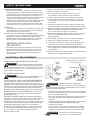 3
3
-
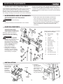 4
4
-
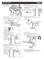 5
5
-
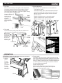 6
6
-
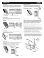 7
7
-
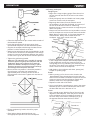 8
8
-
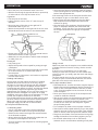 9
9
-
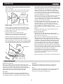 10
10
-
 11
11
-
 12
12
-
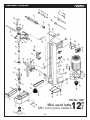 13
13
-
 14
14
-
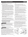 15
15
-
 16
16
-
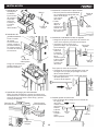 17
17
-
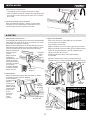 18
18
-
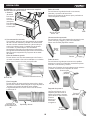 19
19
-
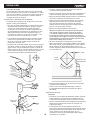 20
20
-
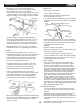 21
21
-
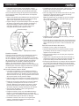 22
22
-
 23
23
-
 24
24
-
 25
25
-
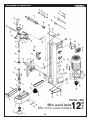 26
26
-
 27
27
-
 28
28


KNOVA KN WL-12M El manual del propietario
- Categoría
- Tornos
- Tipo
- El manual del propietario
En otros idiomas
- English: KNOVA KN WL-12M Owner's manual
Otros documentos
-
Craftsman 351.217520 El manual del propietario
-
-
-
-
DeWalt LA200 Manual de usuario
-
Delta 46-460 Manual de usuario
-
-
-
-
Holzmann D 460FXL Manual de usuario