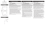
start here
commencez ici
empezar aquí
Assembly Instructions
Item No: 32506 / 32508
Les Instructions D’assemblage
Numéro d’article: 32506 / 32508
Instrucciones De Montaje
Número del artículo: 32506 / 32508
English Spanish French
1. Find a clear area in which you can work.
2. Unpack fixture and glass from carton.
3. Carefully review instructions prior to assembly.
1. Encontrar un área clara en la que se puede trabajar.
2. Desembale luminaria y el vidrio de la caja.
3. Revise cuidadosamente las instrucciones antes del montaje.
1. Trouvez un endroit clair dans lequel vous pouvez travailler.
2. Déballez luminaire et de verre du carton.
3. Examinez attentivement les instructions avant l'assemblage.
Safety Warning: read wiring and grounding instructions (I.S. 18) and any
additional directions, Turn power supply off during installation. If new
wiring is required, consult a qualified electrician or local authorities for
code requirements.
Advertencia de seguridad: lea las instrucciones de cableado y conexión a
tierra (I.S. 18) y cualquier otra instrucción adicional. Apague la fuente de
alimentación durante la instalación. Si se requiere un nuevo cableado,
consulte a un electricista calificado o a las autoridades locales para
conocer los requisitos del código.
Avertissement de sécurité: lire les instructions de câblage et de mise à la
terre (I.S. 18) et toute autre instruction supplémentaire. Couper l'alimenta-
tion électrique pendant l'installation. Si un nouveau câblage est nécessaire,
consultez un électricien qualifié ou les autorités locales pour les exigences
du code.
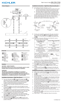
STEM
TALLO
TIGE
STEM
TALLO
TIGE
STEM
TALLO
TIGE
1
SWIVEL
GIRAR
PIVOT
A
1
S
MOUNTING
BRACKET
MONTAJE
SOPORTE
MONTAGE
PLAQUE
2
2
1. Para montar su accesorio al techo. Levante el ensamblaje
superior del accesorio hasta la caja de conexiones, y utilizando dos
tornillos (S) NO PROPORCIONADOS. Fije la placa de montaje a la
caja de conexiones - vea el Dibujo 2.
2. Luego realice todas las conexiones de cableado siguiendo el
diagrama de cableado y las instrucciones proporcionadas.
1. To mount your fixture to the ceiling. Lift top assemby of fixture up to
junction box, and using two screws (S) NOT PROVIDED. Attach mounting
plate to junction box - see Drawing 2.
2. Next make all wiring connections following wiring diagram and instruc-
tions provided.
1. Pour monter votre appareil au plafond. Soulevez le haut du
luminaire jusqu'à la boîte de jonction et utilisez deux vis (S) NON
FOURNIES. Fixez la plaque de montage à la boîte de jonction - voir
dessin 2.
2. Procéder ensuite à toutes les connexions de câblage en suivant le
schéma de câblage et les instructions fournies.
REMARQUE: PENDANT LE PROCESSUS DE CÂBLAGE, NE PAS
CONNECTER LE FIL NOIR OU ROUGE DE VOTRE APPAREIL AUX
FILS D'ALIMENTATION PROVENANT DE LA BOÎTE DE JONCTION
ET ALLUMER L'ALIMENTATION. IL ENDOMMAGERA LES PUCES
DEL ET L'APPAREIL DEVRAIT ÊTRE REMPLACÉ À FRAIS DE
CLIENT.3. Compléter l'installation de l'auvent (2) le long des tiges et
jusqu'au plafond, suivi du collier de serrage (1).
REMARQUE: LA CANOPY PEUT ÊTRE CÂBLÉE À UN INTERRUPT-
EUR DE SEPARATION SI VOUS SOUHAITEZ. SUIVRE L'INSTRUC-
TION DE CÂBLAGE FOURNIE.
4. Après le câblage, tenir l'auvent jusqu'au plafond et visser le collier
de vis (1) pour fixer l'auvent
en place.
NOTE: ADDITIONAL MOUNTING AND PLASTIC ANCHORS (X) ARE SUPPLIED
AND CAN BE USED FOR ADDITIONAL SUPPORT OF THE FIXTURE. HOWEVER
THESE SCREWS MAY NOT WORK WITH YOU PERTICULAR APPLICATION.
APPROPRIATE HARDWARE SHOULD BE PURCHASED FOR YOUR APPLICA-
TION.
NOTE: DURING THE WIRING PROCESS DO NOT CONNECT THE
BLACK OR RED WIRE FROM YOUR FIXTURE TO THE SUPPLY WIRES
COMING FROM THE JUNCTION BOX AND TURN ON THE POWER. IT
WILL DAMAGE THE LEDS CHIPS AND THE FIXTURE WILL HAVE TO BE
REPLACED AT CUSTOMERS EXPENSE.
3. To complete installation slip canopy (2) along stems and up to ceilling,
followed by screw collar (1).
NOTE: THE CANOPY CAN BE WIRED TO A SEPERATE SWITCH IF
DESIRED. FOLLOW WIRING INSTRUCTION PROVIDED.
4. After wiring hold canopy up to ceiling and thread on screw collar (1) to
secure canopy
in place.
{DRAWING 1}
{DRAWING 2}
X
NOTA: SE SUMINISTRAN ANCLAJES ADICIONALES DE MONTAJE Y
PLÁSTICO (X) Y PUEDEN UTILIZARSE PARA APOYO ADICIONAL DEL
ACCESORIO. SIN EMBARGO, ESTOS TORNILLOS PUEDEN NO FUNCIONAR
CON SU APLICACIÓN PERTÍTULA.
HARDWARE APROPIADO DEBE SER ADQUIRIDO PARA SU APLICACIÓN.
NOTA: DURANTE EL PROCESO DE CABLEADO NO CONECTE
EL ALAMBRE NEGRO O ROJO DE SU ACCESORIO A LOS
ALAMBRES DE SUMINISTRO PROCEDENTES DE LA CAJA DE
CONEXIONES Y ENCIENDA LA ALIMENTACIÓN. DAÑARÁ LOS
CHIPS DE LOS LEDS Y EL ARTEFACTO DEBERÁ REEMPLA-
ZARSE A CARGO DEL CLIENTE.
Para completar la cubierta antideslizante de instalación (2) a lo largo
de los tallos y hasta el techo, seguido del collar roscado (1).
NOTA: LA CANOPY PUEDE CONECTARSE CON UN INTERRUP-
TOR SEPARADO SI SE DESEA. SIGA LA INSTRUCCIÓN DE
CABLEADO PROPORCIONADA.
4. Después del cableado sostenga el dosel hasta el techo y enrosque
el collar roscado (1) para asegurar el dosel
en su lugar.
REMARQUE: DES ANCRAGES SUPPLÉMENTAIRES DE MONTAGE ET DE
PLASTIQUE (X) SONT FOURNIS ET PEUVENT ÊTRE UTILISÉS POUR UN
SUPPORT SUPPLÉMENTAIRE DE L'APPAREIL. TOUTEFOIS, CES VIS PEUVENT
NE PAS FONCTIONNER AVEC VOTRE APPLICATION PERTICULAIRE.
UN MATÉRIEL APPROPRIÉ DOIT ÊTRE ACHETÉ POUR VOTRE APPLICATION.
REVISED 122117 HINKLEY 33000 Pin Oak Parkway, Avon Lake, OH 44012 800.446.5539 / 440.653.5500 hinkley.com
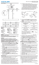
1. After the required stem lengths, needed to hang your fixture are determined.
Start assembling the stems by slipping the fixtures black and red wires through
the center of the first stem and thread it onto threaded tube (A). Continue adding
stems in this manner until all the required stems are threaded together.
2. When last stem is assembled then slip screw collar ring (1) along black and
red wire a over the stems. This is followed by canopy (2).
3. Next take the black and red wires and slip them though the swivel that is
attached to the
mounting bracket. Make sure to slip wires out one side of the mounting bracket
4. Now thread swivel into the top of the last ste
5. Fixture is ready for installation
1. Después de las longitudes de tubería requeridas, se deter -
nan las necesarias para colgar su accesorio. Comience a ensam-
blar las tuberías deslizando los cables negro y rojo por el centro
de la primera tubería y enrosque el tubo roscado (A). Continúe
agregando tuberías de esta manera hasta que todas las tuberías
necesarias estén enroscadas juntas.
2. Cuando se ensamble el último tubo, deslice el anillo del collar
del tornillo (1) a lo largo del cable negro y rojo y sobre los vásta-
gos. Esto es seguido por dosel (2).
3. A continuación, tome los cables negro y rojo y deslícelos a
través de la pieza giratoria que está unida al soporte de montaje.
Asegúrese de deslizar los cables por un lado del soporte de
montaje.
4. Ahora enrosque el eslabón giratorio en la parte superior del
último vástago.
5. El accesorio está listo para la instalació
1. Après les longueurs de tuyau requises, les nécessaires sont
déterminées pour accrocher votre accessoire. Commencez à
assembler les tuyaux en faisant glisser les fils noirs et rouges à
travers le centre du premier tuyau et vissez le tuyau fileté (A).
Continuez à ajouter des tuyaux de cette manière jusqu'à ce que
tous les tuyaux nécessaires soient vissés ensemble.
2. Lorsque le dernier tube est assemblé, faites glisser le collier
collier de vis (1) le long du câble noir et rouge et au-dessus des
tiges. Ceci est suivi par canopée (2).
3. Ensuite, prenez les fils noir et rouge et faites-les glisser à trave
la partie pivot qui est attachée au support de montage. Veillez à
faire glisser les câbles d'un côté du support de montage.
4. Vissez maintenant l'émerillon au-dessus de la dernière tige.
5. L'accessoire est prêt pour l'installatio


 1
1
 2
2
 3
3
 4
4
Hinkley T24 JA8-2016 Instrucciones de operación
 Hinkley FR47756BNG Manual de usuario
 Hinkley 34106BNG Manual de usuario
Hinkley 3266PW Manual de usuario
 Kichler Lighting 44340WNWLED Manual de usuario
 Hinkley 29307 Rhodes 1 Light Outdoor Hanging Lantern Manual de usuario
 Hinkley Lighting 4811KZ Guía de instalación
Hinkley Lighting 3122KZ Guía de instalación
LARK 83194 Manual de usuario
 Kichler Lighting 44344WNWLED Manual de usuario


