Nobles Speed Scrub 2601 Operator And Parts Manual
- Categoría
- Máquina de piso
- Tipo
- Operator And Parts Manual

ENGLISH - ESPAÑOL
Operator and Parts Manual
Manual del Operador y Piezas
Cylindrical Brush Automatic Scrubber
Limpiador Automático de Cepillo Cilíndrico
Model No.:
1002193
613614
Rev. 00 (12-02)
CUSTOMER SERVICE: 1-800-365-6625
FAX: 1–800–678–4240
NOBLES
12875 RANSOM STREET
HOLLAND MI 49424 U.S.A.
Speed Scrub 2601
t

OPERATION
2Speed Scrubt 2601 Cylindrical Brush (12–02)
This manual is furnished with each new model. It
provides necessary operation and maintenance
instructions and an illustrated parts list.
Read this manual completely and understand the
machine before operating or servicing it.
When ordering replacement parts, use the parts list
section in this manual. Before ordering parts or
supplies, be sure to have your machine model number
and serial number available. Parts and supplies may
be ordered by phone or mail from any authorized
Service Center or Distributor.
This machine will provide excellent service. However,
the best results will be obtained at minimum costs if:
SThe machine is operated with reasonable care.
SThe machine is maintained regularly - per the
machine maintenance instructions provided.
SThe machine is maintained with manufacturer
supplied or equivalent parts.
MACHINE DATA
Please fill out at time of installation for future reference.
Model No.-
Install. Date -
Serial No.-
E2002 Tennant Company Printed in U.S.A.
Nobles and Speed Scrub are registered United States trademarks of Tennant
Company.
Specifications and parts are subject to change without notice.

OPERATION
3
Speed Scrubt 2601 Cylindrical Brush (12–02)
TABLE OF CONTENTS (ESPAÑOL ÍNDICE....24)
SAFETY PRECAUTIONS 4. . . . . . . . . . . . . . . . . . . .
WARNING LABELS 5. . . . . . . . . . . . . . . . . . . . . . . . .
MACHINE COMPONENTS 6. . . . . . . . . . . . . . . . . . .
CONTROL PANEL SYMBOLS 6. . . . . . . . . . . . . . .
MACHINE INSTALLATION 7. . . . . . . . . . . . . . . . . . .
UNCRATING MACHINE 7. . . . . . . . . . . . . . . . . .
INSTALLING BATTERIES 7. . . . . . . . . . . . . . . .
MACHINE SETUP 8. . . . . . . . . . . . . . . . . . . . . . . . . .
ATTACHING SQUEEGEE ASSEMBLY 8. . . . .
INSTALLING BRUSHES 8. . . . . . . . . . . . . . . . . .
FILLING SOLUTION TANK 9. . . . . . . . . . . . . . .
ADJUSTING CONTROL GRIP HEIGHT 9. . . .
MACHINE OPERATION 10. . . . . . . . . . . . . . . . . . . . .
PRE–OPERATION CHECKS 10. . . . . . . . . . . . . .
OPERATING MACHINE 10. . . . . . . . . . . . . . . . . .
WHILE OPERATING MACHINE 11. . . . . . . . . . .
STOPPING MACHINE 11. . . . . . . . . . . . . . . . . . .
EMERGENCY STOPPING (OPTION) 11. . . . . .
CIRCUIT BREAKERS 12. . . . . . . . . . . . . . . . . . . .
DRAINING TANKS 12. . . . . . . . . . . . . . . . . . . . . . . . . .
DRAINING RECOVERY TANK 12. . . . . . . . . . . .
DRAINING SOLUTION TANK 13. . . . . . . . . . . . .
ADJUSTING BRUSHES 13. . . . . . . . . . . . . . . . . . . . .
TO ADJUST BRUSH WITH UNEVEN
PATTERN: 13. . . . . . . . . . . . . . . . . . . . . . . . . . . . . .
TO ADJUST BRUSH WITH TAPERED
PATTERN: 14. . . . . . . . . . . . . . . . . . . . . . . . . . . . . .
CHARGING BATTERIES 14. . . . . . . . . . . . . . . . . . . .
MACHINE MAINTENANCE 16. . . . . . . . . . . . . . . . . .
DAILY MAINTENANCE 16. . . . . . . . . . . . . . . . . . .
WEEKLY MAINTENANCE 17. . . . . . . . . . . . . . . .
MONTHLY MAINTENANCE 17. . . . . . . . . . . . . . .
QUARTERLY MAINTENANCE 18. . . . . . . . . . . .
BATTERY MAINTENANCE 18. . . . . . . . . . . . . . .
TRANSPORTING MACHINE 19. . . . . . . . . . . . . . . . .
STORING MACHINE 19. . . . . . . . . . . . . . . . . . . . . . . .
RECOMMENDED STOCK ITEMS 19. . . . . . . . . . . . .
TROUBLE SHOOTING 20. . . . . . . . . . . . . . . . . . . . . .
SPECIFICATIONS 22. . . . . . . . . . . . . . . . . . . . . . . . . .
MACHINE DIMENSIONS 23. . . . . . . . . . . . . . . . . . . .
ELECTRICAL DIAGRAMS 48. . . . . . . . . . . . . . . . . . .
PARTS LIST 50. . . . . . . . . . . . . . . . . . . . . . . . . . . . . . .
SOLUTION TANK GROUP 50. . . . . . . . . . . . . . . .
RECOVERY TANK GROUP 52. . . . . . . . . . . . . . .
CONSOLE GROUP 54. . . . . . . . . . . . . . . . . . . . . .
ELECTRICAL / BATTERY GROUP 56. . . . . . . .
DRIVE GROUP 58. . . . . . . . . . . . . . . . . . . . . . . . .
SCRUB HEAD ACTUATOR GROUP 60
SCRUB HEAD GROUP 62. . . . . . . . . . . . . . . . . .
SOLUTION CONTROL GROUP 66. . . . . . . . . . .
SQUEEGEE CONTROL GROUP 68. . . . . . . . . .
SQUEEGEE ASSEMBLY GROUP –
838mm (33 in) 70. . . . . . . . . . . . . . . . . . . . . . . . . . .
OPCIONES 72. . . . . . . . . . . . . . . . . . . . . . . . . . . . . . . .
ES KIT 72. . . . . . . . . . . . . . . . . . . . . . . . . . . . . . . . .
SQUEEGEE WAND ASSEMBLY 74. . . . . . . . . .
HOUR METER, EMERGENCY STOP,
KEYSWITCH AND LOW VOLTAGE KITS 75. . .

OPERATION
4Speed Scrubt 2601 Cylindrical Brush (12–02)
SAFETY PRECAUTIONS
This machine is intended for commercial use. It is
designed exclusively to scrub hard floors in an
indoor environment and is not constructed for any
other use. Use only recommended commercially
available floor cleaners intended for machine
application.
All operators must read, understand and practice
the following safety precautions.
The following warning alert symbol and the “FOR
SAFETY” heading are used throughout this manual as
indicated in their description:
WARNING: To warn of hazards or unsafe
practices which could result in severe personal
injury or death.
FOR SAFETY: To identify actions which must be
followed for safe operation of equipment.
Failure to follow these warnings may result in:
personal injury, electrocution, electrical shock,
fire or explosion.
WARNING: Do Not Use Flammable Liquids Or
Operate Machine In Or Near Flammable Liquids,
Vapors Or Combustible Dusts.
This machine is not equipped with explosion
proof motors. The electric motors will spark upon
start up and during operation which could cause a
flash fire or explosion if machine is used in an
area where flammable vapors/liquids or
combustible dusts are present.
WARNING: Do Not Pick Up Flammable
Materials Or Reactive Metals.
WARNING: Keep Sparks And Open Flame
Away. Keep Battery Hood Open When Charging.
WARNING: Disconnect Battery Cables Before
Servicing Machine.
WARNING: Moving Parts. Turn Off Power
Before Working On Machine.
The following information signals potentially
dangerous conditions to the operator or
equipment:
FOR SAFETY:
1. Do not operate machine:
–With flammable liquids or near flammable
vapors as an explosion or flash fire may
occur.
–Unless trained and authorized.
–Unless operation manual is read and
understood.
–If not in proper operating condition.
2. Before starting machine:
–Make sure all safety devices are in place
and operate properly.
3. When using machine:
–Go slow on inclines and slippery surfaces.
–Wear no–slip shoes.
–Use care when reversing machine.
–Report machine damage or faulty
operation immediately.
–Never allow children to play on or around.
–Follow mixing and handling instructions
on chemical containers.
4. Before leaving or servicing machine:
–Stop on level surface.
–Turn off machine.
5. When servicing machine:
–Avoid moving parts. Do not wear loose
jackets, shirts, or sleeves.
–Use hoist or jack that will support the
weight of the machine.
–Block machine tires before jacking up.
–Wear eye and ear protection when using
pressurized air or water.
–Disconnect battery connections before
working on machine.
–Wear protective gloves and safety glasses
when handling batteries or battery cables.
–Avoid contact with battery acid.
–Use manufacturer supplied or approved
replacement parts.
–All repairs must be performed by a
qualified service person.
–Do not modify the machine from it’s
original design.

OPERATION
5
Speed Scrubt 2601 Cylindrical Brush (12–02)
6. When transporting machine:
–Turn machine off.
–Get assistance when lifting machine.
–Do not lift machine when batteries are
installed.
–Use a recommended ramp when
loading/unloading into/off truck or trailer.
–Use tie–down straps to secure machine to
truck or trailer.
WARNING LABELS
The warning labels appear on the machine in the
locations indicated. Replace labels if they become
damaged or illegible.
MOVING PARTS LABEL – LOCATED
ON THE BRUSH HEAD SHROUD.
WARNING LABEL – LOCATED ON THE RECOVERY TANK.
WARNING: Keep sparks
and open flame away. Keep
battery hood open when
charging.
WARNING: Moving parts.
Turn off power before working
on machine.
BATTERY CHARGE LABEL –
LOCATED INSIDE BATTERY
COMPARTMENT.

OPERATION
6Speed Scrubt 2601 Cylindrical Brush (12–02)
MACHINE COMPONENTS
11
10 9
4
7
6
5
22
13
21
23
19
2
16
8
20
12
1
27
28 29
30
32
33
2
36
17
26
3
14
15
24
25
18
37 38
18
34
39
31
35
1. Control Console
2. Control Twist Grips
3. Key Switch (Optional)
4. Main Power ON/OFF Switch
5. Vacuum ON/OFF Switch
6. Solution ON/OFF Switch
7. Brush Pressure Switch
8. Brush Pressure Meter
9. Battery Meter
10. Reverse Switch
11. Speed Control Knob
12. Power Kill Button (Optional)
13. Main, Vac/Drive Circuit Breakers
14. Squeegee Lift Lever
15. Low Voltage Meter (Optional)
16. Solution Flow Adjustment Knob
17. ESt Switch (Optional)
18. Wall Rollers
19. Adjustable Control Console Levers
20. Recovery Tank Drain Hose
21. Solution Tank Drain Hose
22. Rear Fill Port
23. Squeegee Assembly
24. Recovery Tank
25. Recovery Tank Lid
26. Solution Tank
27. Solution Tank Fill Door
28. Safety Lights
29. Battery Compartment
30. Charger Plug
31. Hour Meter (Optional)
32. Drive Wheels
33. Rear Casters
34. Cylindrical Brush Scrub Head
35. Solution Feed Hose/Trough
36. Scrub Head Skirt
37. Brush Idler Plate
38. Idler Plate Latch
39. Debris Trough
CONTROL PANEL SYMBOLS
Main Power
Vacuum Fast Speed
Slow Speed Reverse
Squeegee Up
Squeegee Down
Battery Meter
Brush Pressure
Meter
Brush
Solution

OPERATION
Speed Scrubt 2601 Cylindrical Brush (12–02) 7
MACHINE INSTALLATION
UNCRATING MACHINE
1. Carefully check carton for signs of damage.
Report damages at once to carrier.
2. Check Carton Contents list, contact distributor for
missing items.
Carton Contents:
–Machine, Model No. 1002193
–24DC/120AC, 20A Battery Charger (#603235)
–2 – 12V, 215 AH Batteries (Installed)
–2– Cylindrical Brushes
–Squeegee Assembly
3. To uncrate the machine, remove the rear and front
shipping brackets that secure the machine to the
pallet. Remove the rear 4x4 board from the pallet
and carefully back the machine off the pallet. The
pallet will tip downward creating a ramp. Make
sure the scrub head is in the raised position.
ATTENTION: Do not push machine off pallet edge,
machine damage may occur.
INSTALLING BATTERIES
WARNING: Keep Sparks And Open Flame
Away. Keep Battery Hood Open When Charging.
FOR SAFETY: When servicing machine, wear
protective gloves and safety glasses when
handling batteries or battery cables. Avoid contact
with battery acid.
Recommended Battery Specifications:
Two 12 volt, deep cycle, 215 A hour batteries.
Maximum battery dimensions are 178mm (7 in) W x
381mm (15 in) L x 356mm (14 in) H.
1. Park the machine on a level surface and turn all
switches to the OFF position.
2. Hinge open recovery tank to access battery
compartment. Make sure recovery tank is drained
before opening (Figure 1).
FIG. 1
3. Carefully install batteries into battery tray at
bottom of compartment and arrange battery posts
as shown (Figure 2).
FIG. 2
ATTENTION: Do not drop batteries into
compartment, battery and machine housing
damage may result. This damage in not covered
by warranty.
4. Before connecting battery cables, make sure
terminals and posts are clean. Use a post cleaner
and wire brush if necessary.
NOTE: Apply a light coating of non-metallic grease or
protective spray on the cable connections to prevent
battery corrosion.
5. Connect cables to battery posts as shown (Figure
2), RED TO POSITIVE & BLACK TO NEGATIVE.
Use the rubber boot post protectors supplied.
6. After batteries are properly installed, check battery
meter charge level. The machine must be in full
operation for an accurate reading (See MACHINE
OPERATION). Charge batteries if needed.

OPERATION
8Speed Scrubt 2601 Cylindrical Brush (12–02)
MACHINE SETUP
ATTACHING SQUEEGEE ASSEMBLY
1. Turn main power switch to the OFF position.
FOR SAFETY: Before leaving or servicing
machine, stop on level surface and turn off
machine.
2. Pull back on squeegee lift lever to raise the
squeegee mount bracket (Figure 3).
FIG. 3
3. Loosen the two thumb knobs on squeegee
assembly and slide squeegee into slots on
squeegee mount bracket (Figure 4).
FIG. 4
4. Tighten thumb knobs securely.
5. Connect vacuum hose from machine to squeegee
assembly (Figure 5).
FIG. 5
INSTALLING BRUSHES
1. Turn the main power switch to the ON position and
raise the scrub head. Press bottom half of brush
pressure switch to raise. Hold switch down until
scrub head actuator turns off (Figure 6).
FIG. 6
2. Then turn main power switch to the OFF position
after raising scrub head.
FOR SAFETY: Before leaving or servicing
machine, stop on level surface and turn off
machine.
3. Remove idler plate from scrub head by releasing
latches on top of scrub head (Figure 7).
FIG. 7

OPERATION
Speed Scrubt 2601 Cylindrical Brush (12–02) 9
4. With the double bristle row end towards you, guide
the brush into the drive hub (Figure 8).
NOTE: Installing the double bristle row end opposite of
drive hub will prevent brush streaking while scrubbing.
DOUBLE ROW
OF BRISTLES FIG. 8
5. Align idler plate on brush end and refasten
latches.
6 Repeat steps for other brush on opposite side of
scrub head.
7. Check for proper brush pattern (see ADJUSTING
BRUSHES).
FILLING SOLUTION TANK
1. Transport machine to filling station. Raise
squeegee and scrub head when transporting.
2. Turn the main power switch to the OFF position.
3. The solution tank is equipped with front and rear
filling ports for your convenience (Figure 9). Fill
solution tank with 64L (17 gal) of clean water,
60°C (140°F) maximum temperature. The clear
tube below the rear fill port indicates the amount of
water in solution tank.
FIG. 9
NOTE: When filling solution tank with a bucket, make
sure that bucket is clean. Do not use the same bucket
for filling and emptying the machine.
4. Pour a recommended cleaning agent into solution
tank according to mixing instructions on bottle.
FOR SAFETY: When using machine, follow mixing
and handling instructions on chemical containers.
ATTENTION: Use only recommended cleaning
agents, DO NOT use substitutes. Consult an
authorized distributor for recommendations.
WARNING: Do Not Use Flammable Liquids Or
Operate Machine In Or Near Flammable Liquids,
Vapors Or Combustible Dusts.
ADJUSTING CONTROL GRIP HEIGHT
The machine has three control grip height settings.
To adjust, squeeze together the two levers below
console and lift or lower console to a comfortable
operating height (Figure 10).
FIG. 10

OPERATION
10 Speed Scrubt 2601 Cylindrical Brush (12–02)
MACHINE OPERATION
FOR SAFETY: Do not operate machine unless
operator manual is read and understood.
PRE–OPERATION CHECKS
SCheck battery meter charge level to ensure
batteries are fully charged (See CHARGING
BATTERIES).
SCheck condition of brushes.
SCheck condition of squeegee blades.
SCheck that debris trough is installed and empty.
OPERATING MACHINE
1. Disengage the squeegee lift lever from the up
position and lower squeegee (Figure 11).
FIG. 11
2. Turn the main power switch to the on position.
3. Lower the scrub head to the floor. Press and hold
top half of brush pressure switch to lower
(Figure 12).
FIG. 12
4. Turn the vacuum and solution switches to the ON
position.
NOTE: The brushes and solution flow will start when
control grips are rotated.
5. Before starting, turn the speed control knob to
slowest setting to avoid an abrupt take–off
(Figure 13).
6. Begin scrubbing by rotating control grips forward.
Gradually increase your speed by turning speed
control knob forward (Figure 13).
FIG. 13
7. Once machine begins to move, check the needle
position of the brush pressure meter. Depress the
brush pressure switch to adjust pressure. Do not
operate machine in the red zone (Figure 14).
FIG. 14
ATTENTION: To prevent floor damage and brush
motor overload, do not operate brush pressure
meter in red zone.
8. To operate machine in reverse, simply pull the
reverse switch backwards (Figure 15).
FIG. 15
9. To stop machine, gradually release the control
grips.

OPERATION
Speed Scrubt 2601 Cylindrical Brush (12–02) 11
WHILE OPERATING MACHINE
WARNING: Do Not Pick Up Flammable
Materials Or Reactive Metals.
FOR SAFETY: When using machine, go slow on
inclines and slippery surfaces.
1. Observe the amount of solution flow on floor. To
increase or decrease water flow, adjust the
solution control knob (Figure 16).
FIG. 16
2. Periodically observe recovery tank for excessive
foam. If excessive foam appears, pour a
recommended foam control solution into recovery
tank.
ATTENTION: Do not allow foam or water to enter
float shut–off screen, vacuum motor damage will
result. Foam will not activate the float shut–off
screen.
3. Always operate at a slower speed when scrubbing
around walls or obstacles.
4. Always reduce speed to maintain control when
turning machine.
5. If squeegee leaves streaks, raise and wipe blades
with a cloth. Pre-sweep area to prevent streaking.
6. Overlap each pass by 51mm (2 in).
7. Change brushes when worn.
8. If you experience excessive brush vibration or
poor scrubbing performance, see ADJUSTING
SCRUB HEAD.
9. Stay clear of floor obstructions, such as electrical
plates or grates, they will destroy brushes.
10. During brief stops, brushes and solution flow will
automatically stop when control grips are
released.
11. Periodically check battery meter discharge level.
When needle nears the red zone, recharge
batteries.
ATTENTION: Do not run machine when battery
meter needle is in the red zone, battery damage
will result.
12. While cleaning, view the clear tube at rear of
machine for remaining cleaning solution.
13. When solution tank runs dry, turn off solution
switch, and continue to vacuum until all dirty water
is consumed. Then drain recovery tank
(see DRAINING TANKS).
14. When cleaning on inclines, always clean moving
downward, never upward. Never climb inclines
that exceed 5 degrees, machine damage may
occur.
STOPPING MACHINE
1. Turn solution switch off and continue to vacuum
until all solution is consumed.
2. Release control grips.
3. Raise squeegee.
4. Turn machine off and remove key if equipped.
FOR SAFETY: Before leaving or servicing
machine, stop on level surface and turn off
machine.
EMERGENCY STOPPING (OPTION)
To stop machine in the case of an emergency, strike
the red power kill button located at rear of control
console. The power kill button immediately stops all
power to machine (Figure 17).
To reset power kill button, shut off all switches and
turn kill button to the right. Resume to normal
operation.
FIG. 17

OPERATION
12 Speed Scrubt 2601 Cylindrical Brush (12–02)
CIRCUIT BREAKERS
The machine is equipped with (4) resettable circuit
breakers to protect machine from damage.
If circuit breakers should trip, the breakers will not
reset immediately upon tripping. Determine cause,
allow motor to cool then manually reset circuit breaker
button.
The brush motor circuit breakers may trip due to
excessive brush pressure. Reduce brush pressure.
Brush motor circuit breakers (25 amp) are located
near the charger plug.
The main (10 amp) and drive/vacuum (35 amp) circuit
breakers are located at rear of machine (Figure 18).
FIG. 18
DRAINING TANKS
FOR SAFETY: Before leaving or servicing
machine, stop on level surface and turn off
machine.
DRAINING RECOVERY TANK
Drain recovery tank:
– After each use.
– Before refilling solution tank.
– When squeegee starts trailing water.
– When solution flow stops.
– When float shut-off screen, located inside
recovery tank, is activated.
–If optional ESt indicator light remains on.
ATTENTION: Do not allow foam or water to enter
float shut–off screen, vacuum motor damage will
result. Foam will not activate the float shut–off
screen.
1. Remove drain hose from holder, position hose
over floor drain and twist off drain hose plug. To
completely drain recovery tank, hinge open tank
and flip up tank support stand to rest tank on
(Figure 19).
NOTE: If using a bucket to drain machine, do not use
same bucket for filling solution tank. This will prevent
possible solution line clogs.
FIG. 19
2. Flush out out recovery tank after each use. Be
careful not to spray water into the float shut–off
screen.
3. Replace drain hose plug securely after draining
and return hose to hook.

OPERATION
Speed Scrubt 2601 Cylindrical Brush (12–02) 13
DRAINING SOLUTION TANK
To drain leftover cleaning solution from solution tank,
perform the following steps:
1. Pull the clear hose off hose barb at rear of
machine and drain solution into floor drain or
bucket (Figure 20).
FIG. 20
2. Rinse out solution tank and solution flow system
with clean water after each use. This will prevent
clogging due to chemical buildup.
3. Reconnect solution tank drain hose securely after
draining.
ADJUSTING BRUSHES
On a monthly basis or after installing new brushes,
check the brush pattern to ensure brushes are
properly adjusted. Brushes that are installed
improperly will result in premature brush wear and
poor scrubbing performance.
NOTE: If machine is equipped with air–filled tires, fill
solution tank before checking or adjusting brushes.
1. Apply a powdered substance, such as chalk, on a
smooth, level floor.
2. With scrub head raised, position scrub head over
test area.
3. Place blocks behind each drive wheel to keep
machine stationary and turn speed control knob to
slowest setting.
4. Lower scrub head to floor and apply maximum
down pressure.
5. Make sure that the solution switch is in the OFF
position.
6. Briefly rotate control grips forward for 2 seconds.
7. Raise scrub head and reverse machine from test
area.
8. Observe brush pattern on floor. Both brushes
should leave an even, parallel pattern (Figure 21).
CORRECT BRUSH PATTERN
INCORRECT BRUSH PATTERNS
Even and
Parallel
Pattern
Tapered
Pattern Uneven
Pattern
FIG. 21
9. If brush pattern represents one of the incorrect
patterns, adjustment is required.
TO ADJUST BRUSH WITH UNEVEN PATTERN:
1. Lower scrub head to floor and apply maximum
down pressure.
2. Turn machine off and remove key if equipped.
FOR SAFETY: Before leaving or servicing
machine, stop on level surface and turn off
machine.
3. Measure the distance from top edge of scrub head
to floor at front and rear. The dimension at front of
scrub head should be 6.35 mm (.25 in) lower than
the rear (Figure 22).
FIG. 22

OPERATION
14 Speed Scrubt 2601 Cylindrical Brush (12–02)
4. To adjust scrub head, slightly loosen the (4) lock
nuts on the roller mounting bracket and the jam
nut on the scrub head leveling knob (Figure 23).
Turn knob clockwise to lower rear of scrub head
and counter–clockwise to lower front. 13mm
socket wrench required.
LOCK NUT
LEVELING
KNOB
FIG. 23
5. After adjustment is made retighten nuts and
recheck brush pattern. Readjust if necessary.
TO ADJUST BRUSH WITH TAPERED PATTERN:
1. Raise scrub head off floor and turn machine off.
FOR SAFETY: Before leaving or servicing
machine, stop on level surface and turn off
machine.
2. Remove the idler plate from scrub head by
releasing latches on top of scrub head (Figure 24).
FIG. 24
3. Remove plate from end of brush.
4. Hold idler hub shaft with 3/8” wrench and loosen
Allen head screw with 6 mm Allen wrench
(Figure 25).
FIG. 25
5. When adjusting front brush, turn shaft clockwise to
lower brush end. If adjusting rear brush, turn shaft
counter–clockwise to lower brush end. Retighten
Allen screw after adjusting (Figure 26).
FIG. 26
6. Replace idler plate and recheck brush pattern.
Readjust if necessary.
CHARGING BATTERIES
To prolong the battery life, ONLY recharge the
batteries if discharged more than 15% of the battery
capacity. When discharged 15% or less, continue to
use the machine before recharging.
Run Time Example: 15% discharge X 3 hours rated
total run time (with maximum brush pressure) = 27
minutes.
The following charging instructions are intended
for chargers supplied with machine.
Use a charger with the following specifications to
prevent battery damage.
BATTERY CHARGER SPECIFICATIONS:
SOUTPUT VOLTAGE - 24 VOLTS
SOUTPUT CURRENT - 25 AMPS
SAUTOMATIC SHUTOFF CIRCUIT
SFOR DEEP CYCLE BATTERY CHARGING

OPERATION
Speed Scrubt 2601 Cylindrical Brush (12–02) 15
NOTE: For optimum machine operation, keep
batteries charged at all times. Never leave batteries
discharged for lengthy periods.
WARNING: Keep Sparks And Open Flame
Away. Keep Battery Hood Open When Charging.
FOR SAFETY: When servicing machine, wear
protective gloves and safety glasses when
handling batteries or battery cables. Avoid contact
with battery acid.
1. Transport the machine to a well–ventilated area
for charging.
2. Park the machine on a level surface and turn main
switch to the off position.
FOR SAFETY: Before leaving or servicing
machine, stop on level surface and turn off
machine.
3. Hinge open recovery tank to access the battery
compartment (Figure 27).
NOTE: Make sure to drain recovery tank prior to
accessing batteries.
FIG. 27
4. Before charging, check the electrolyte level (A) in
each battery cell. If battery plates (B) are exposed,
add just enough distilled water to cover plates. DO
NOT OVERFILL. Overfilled batteries can overflow
during charging due to fluid expansion. Replace
cell caps before charging (Figure 28).
A
B
FIG. 28
5. With the charger’s power supply cord unplugged,
connect battery charger into machine’s charging
receptacle, as shown. Rest the recovery tank on
the support stand to promote ventilation
(Figure 29).
FIG. 29
6. Plug the charger’s power supply cord into a
grounded wall outlet (Figure 30).
Grounded
3 Hole Outlet
Ground Pin
(120V)
FIG. 30
WARNING: Keep Sparks And Open Flame
Away. Keep Battery Hood Open When Charging.
NOTE: Once charger is connected, the machine will
become inoperable.
7. Charger will automatically begin charging and shut
off when fully charged.
8. When disconnecting charger, always unplug
charger from wall outlet first.
9. After charging, recheck the battery electrolyte
level (A) in each battery cell. The level should be 1
cm (3/8 in.) from the bottom of sight tubes (B)
(Figure 31). Add distilled water if needed. DO NOT
OVERFILL.
A
B
FIG. 31

OPERATION
16 Speed Scrubt 2601 Cylindrical Brush (12–02)
MACHINE MAINTENANCE
To keep machine in good working condition, simply
follow the daily, weekly and monthly maintenance
procedures.
FOR SAFETY: Before leaving or servicing
machine, stop on level surface and turn off
machine.
WARNING: Disconnect Battery Cables Before
Servicing Machine.
ATTENTION: Contact an Authorized Service
Center for machine repairs. Machine repairs
performed by other than an authorized person will
void your warranty.
DAILY MAINTENANCE
(Every 4 Hours of Operation)
1. Drain and rinse tanks thoroughly (Figure 32). After
draining tanks, hinge recovery tank until you can
see vacuum intake hole at rear of tank. Remove
any debris in hole if necessary.
FIG. 32
2. Remove and rinse off the float shut–off screen
located in recovery tank (Figure 33).
FIG. 33
3. Empty and rinse out debris trough (Figure 34).
FIG. 34
4. Wipe blades down with a dry cloth and store
squeegee in the up position to prevent squeegee
damage (Figure 35). Check squeegee blades for
damage and wear. Rotate or replace blades when
worn or damaged.
FIG. 35
To replace or rotate the front squeegee blade,
unthread the six thumbscrews and remove
retainer band and squeegee blade from squeegee
frame. Replace or rotate blade end for end to
allow a new edge to face forward (Figure 36).
To replace the rear squeegee blade, unlatch
retainer clamp and remove retainer band and
squeegee blade from squeegee frame. Replace or
rotate blade end for end or top to bottom to allow a
new edge to face forward (Figure 36).
FIG. 36

OPERATION
Speed Scrubt 2601 Cylindrical Brush (12–02) 17
5. Check brushes for wear and entangled debris.
Change brushes if bristles are worn to a length of
10mm (0.38 in.) or less (Figure 37).
FIG. 37
6. Check scrub head skirts for wear and adjustment.
Skirts should touch floor, adjust if necessary
(Figure 38). Replace if damaged.
FIG. 38
NOTE: Always replace brushes as a set. Never
replace just one.
7. Clean machine housing with a nonabrasive,
nonsolvent cleaner (Figure 39).
FIG. 39
ATTENTION: Do not power spray or hose off
machine. Electrical component damage may
result.
8. Rinse out solution feed trough.
9. Recharge batteries if needed.
NOTE: To prolong the battery life, ONLY recharge the
batteries if discharged more than 15% of the battery
capacity.
WEEKLY MAINTENANCE
(Every 20 Hours of Operation)
1. Remove the solution tank filter and rinse out.
Before removing filter, be certain solution tank is
empty. Filter is located under machine at rear
(Figure 40).
FIG. 40
2. Check electrolyte level in each battery cell (see
BATTERY MAINTENANCE).
3. Clean battery tops with to prevent corrosion (see
BATTERY MAINTENANCE).
4. Check for loose or corroded battery cables.
MONTHLY MAINTENANCE
(Every 80 Hours of Operation)
1. Flush solution system with a mixture of water and
a recommended neutralizer liquid to dissolve
chemical buildup. Pour 11.3 Liters (3 gals) of clean
water into solution tank, 60°C (140°F) maximum
temperature. Add neutralizer liquid according to
mixing instructions. Over a floor drain, briefly
operate machine, ESt option, and wand option
for 30 seconds each. Turn machine off and leave
machine sit overnight. Next day, disperse
remaining mixture then rinse solution system with
clean water.
NOTE: Contact your chemical supplier for a
recommended neutralizer liquid.
FOR SAFETY: When using machine, follow mixing
and handling instructions on chemical containers.
2. Check brush pattern for proper adjustment (see
ADJUSTING BRUSHES).
3. Lubricate caster grease fittings with a water
resistant grease (Figure 41).

OPERATION
18 Speed Scrubt 2601 Cylindrical Brush (12–02)
FIG. 41
4. Lubricate all linkage pivot points with silicone
spray then coat with a water resistant grease to
maintain a smooth operation.
5. Check brush belt tension. Proper belt deflection
should be 6.35 mm (0.25 in) at midpoint, with
5.44–5.81 Kg (12.0–12.8 lbs) force (Figure 42).
FOR SAFETY: When servicing machine,
disconnect battery connections before working on
machine.
FIG. 42
To adjust belt tension, loosen the two motor mount
screws and turn adjustment screw (Figure 43).
Retighten screws and jam nut after adjusting.
FIG. 43
ATTENTION: Contact an Authorized Service
Center for machine repairs.
6. Check machine for water leaks and loose nuts and
bolts.
QUARTERLY MAINTENANCE
(Every 250 Hours of Operation)
Check drive, vacuum and brush motors for carbon
brush wear, replace brushes if worn to a length of
10mm (0.38 in) or less.
Contact an Authorized Service Center for carbon
brush inspection.
FOR SAFETY: When servicing machine, all repairs
must be performed by a qualified service person.
BATTERY MAINTENANCE
The lifetime of the batteries is limited by the number of
charges the batteries receive. To get the most life from
the batteries, maintain the proper level of electrolyte
and only recharge when discharged more than 15% of
battery capacity.
WARNING: Keep Sparks And Open Flame
Away. Keep Battery Hood Open When Charging.
FOR SAFETY: When servicing machine, wear
protective gloves and safety glasses when
handling batteries or battery cables. Avoid contact
with battery acid.
1. Always follow proper charging instructions
(see CHARGING BATTERIES).
2. Check fluid level (A) in each battery cell. The fluid
level should be 1 cm (3/8 in.) from the bottom of
sight tubes after charging. Add distilled water if
needed. DO NOT OVERFILL. Overfilled batteries
can overflow during charging due to fluid
expansion (Figure 44).
A
FIG. 44
3. After charging batteries, measure the specific
gravity in each battery cell using a hydrometer
(Figure 45). This will determine the charge level
and condition of the batteries. If one or more of
the battery cells test lower than the other battery
cell (0.050 or more), the cell is damaged,
shortened, or is about to fail.
NOTE: Do not take reading immediately after adding
distilled water. The water and acid must be thoroughly
mixed in order for accurate reading.

OPERATION
Speed Scrubt 2601 Cylindrical Brush (12–02) 19
FIG. 45
SPECIFIC GRAVITY
at 275C (805F) BATTERY
CHARGE
1.265 100% CHARGED
1.223 75% CHARGED
1.185 50% CHARGED
1.148 25% CHARGED
1.110 DISCHARGED
NOTE: Add or subtract 0.004 gravity reading for each
6_C (10_F) above or below 27_C (80_F).
4. Keep battery tops and terminals clean and dry.
To clean batteries:
a. Mix a strong solution of baking soda and water
(Figure 46).
FIG. 46
b. Brush solution sparingly over battery tops,
terminal and cable connectors.
NOTE: Do not allow baking soda solution to enter
battery cells.
c. Use wire brush to clean terminal post and
cable connections.
d. After cleaning, apply a coating of clear battery
post protectant to terminals and cable
connections.
5. Check for loose or worn cables. Replace if worn.
TRANSPORTING MACHINE
When transporting machine by use of trailer or truck,
be certain to follow tie–down procedures below:
FOR SAFETY: When using machine, go slow on
inclines and slippery surfaces.
1. Remove squeegee and raise scrub head.
2. Load machine using a recommended loading ramp.
To prevent machine damage, do not climb ramps
that exceed 9 degrees.
3. Position front of machine up against front of trailer
or truck. Once machine is positioned, lower scrub
head.
4. Place a block behind each drive wheel and rear
casters.
5. Place tie–down straps over top of machine and
secure straps to floor. It may be necessary to install
tie–down brackets to the floor of your trailer or truck.
NOTE: Do not use the control grips to secure machine
when transporting.
FOR SAFETY: When transporting machine, use a
recommended ramp when loading/unloading
into/off truck or trailer, use tie–down straps to
secure machine to truck or trailer.
STORING MACHINE
1. Before storing machine, be certain to flush tanks
and drain machine of all water.
2. Store machine in a dry area with squeegee
removed and scrub head in the raised position.
3. Remove recovery lid to promote air circulation.
ATTENTION: If storing machine in freezing
temperatures, be certain to drain machine of all
water. Damage due to freezing temperatures is not
covered by warranty.
ATTENTION: Do not expose machine to rain, store
indoors.
RECOMMENDED STOCK ITEMS
Refer to Parts List section for recommended stock
items. Stock Items are clearly identified with a bullet
preceding the parts description. See example below:

OPERATION
20 Speed Scrubt 2601 Cylindrical Brush (12–02)
TROUBLE SHOOTING
PROBLEM CAUSE SOLUTION
No power. Faulty main switch. Contact Service Center.
Batteries need charging. See CHARGING BATTERIES.
Faulty battery(s). Replace battery(s).
Loose battery cable. Tighten loose cable.
MAIN circuit breaker has tripped. Determine cause and reset circuit
breaker button.
Optional power kill button activated. Turn button clockwise to reset.
Brush motors do not operate. Control grips are not rotated. Rotate control grips.
Brush circuit breaker(s) has tripped. Clean or replace brushes and reset
brush circuit breaker button.
Faulty brush motor or wiring. Contact Service Center.
Carbon brushes worn. Contact Service Center.
Faulty brush roll switch or solenoid. Contact Service Center.
Vacuum motor does not operate. Faulty vacuum switch. Contact Service Center.
Vacuum circuit breaker has tripped. Remove obstruction and reset
breaker.
Faulty vacuum motor or wiring. Contact Service Center.
Carbon brushes worn. Contact Service Center.
Drive motor does not operate. Drive motor circuit breaker has
tripped. Determine cause and reset breaker.
Faulty speed control circuit board or
connection. Contact Service Center.
Faulty solenoid. Contact Service Center.
Faulty drive motor. Contact Service Center.
Faulty wiring. Contact Service Center.
Worn carbon brushes. Contact Service Center.
Drive motor operates improperly. Faulty potentiometer or speed control
board. Contact Service Center.
Loose wire connection Contact Service Center.
Little or no solution flow. Solution flow adjustment knob needs
adjusting. Turn solution flow knob clockwise to
increase flow.
Solution line or solution tank filter is
clogged. Remove hose and blow compressed
air through it. Clean solution tank filter
Flush solution tank after each use.
Solution valve or solenoid is clogged. Remove valve or solenoid and clean.
Do not scratch inside of valve.
Faulty solution switch or solenoid. Contact Service Center.
Loose set screw on solution knob. Calibrate knob and retighten screw.

OPERATION
Speed Scrubt 2601 Cylindrical Brush (12–02) 21
TROUBLE SHOOTING –continued
PROBLEM CAUSE SOLUTION
Poor water pick up. Recovery tank is full. Empty recovery tank.
Ball float shut–off screen inside recov-
ery tank is clogged. Remove screen and clean.
Squeegee is clogged with debris. Clean squeegee.
Squeegee blades are worn. Replace or rotate squeegee blades.
Squeegee mount thumbscrews are
loose. Tighten thumbscrews.
Vacuum hose connections are loose
or hose is damaged. Push hose cuffs firmly on connections.
Replace hose if damaged.
Vacuum hose is clogged with debris. Remove clogged debris.
Recovery tank inlet hole is obstructed. Empty recovery tank and tilt tank side-
ways to access inlet hole, remove
obstruction.
Recovery tank gasket is defective. Replace gasket.
Drain hose plug is loose. Tighten drain plug.
Recovery tank lid is loose. Tighten lid.
Vacuum motor is loose. Contact Service Center.
Battery charge level is low. Charge batteries. Do not run machine
when battery meter is in the red zone.
Short run time. Batteries not fully charged. Charge batteries.
Bad cell in one or more batteries. Replace battery.
Batteries need maintenance. See BATTERY MAINTENANCE.
Faulty charger. Replace battery charger.
Safety lights do not work. Flasher is burned out. Contact Service Center.

OPERATION
22 Speed Scrubt 2601 Cylindrical Brush (12–02)
SPECIFICATIONS
MODEL SPEED SCRUBt 2601
LENGTH 1350 mm (53 in)
WIDTH 730 mm (28.75 in)
HEIGHT 990 mm (39 in)
WEIGHT 152 kg (335 lb)
254 Kg (560 lb) with batteries
SOL./REC TANK CAPACITY 64 L (17 Gal)
SPEED CONTROL Variable Fwd. / Fixed Rev.
CLEANING SPEED (MAX) 76.2 m2 (250 ft) per minute
CLEANING PATH WIDTH 660 mm (26 in)
BRUSH DIAMETER 2 – 152mm (6 in)
BRUSH PRESSURE Variable 0–41 Kg (0– 90 lbs)
SQUEEGEE WIDTH 839 mm (33 in)
DRIVE SYSTEM Transaxle, .2 h.p., 24V
BRUSH MOTOR 2 – .75 h.p., 1500 rpm, 24V, 23A, 550W
VACUUM MOTOR .75 h.p., 3–stage 5.7, 24V, 21A, 550W
WATER LIFT / AIR FLOW 1727 mm (68 in) / 69cfm (2m3) per minute
BATTERIES 2–12V, 215AH
TOTAL POWER CONSUMPTION 24V, 53 AMP Nominal
RUN TIME PER CHARGE Up to 4 3/4 hours (3 hours using maximum brush pressure)
DECIBEL RATING AT OPERATOR’S EAR, INDOORS ON
TILE. 75 dB(A)
Specifictions are subject to change without notice.


OPERACIÓN
24 Speed Scrubt 2601 Cepillo Cilíndrico (12–02)
Este manual se proporciona con cada nuevo modelo.
Proporciona instrucciones necesarias de
mantenimiento y lista ilustrada de piezas.
Antes de operar o prestar servicio a la máquina,
lea completamente este manual y entienda la
máquina.
Para ordenar piezas use las Listas Ilustradas de las
Piezas. Asegúrese de tener listo el número de modelo
y de serie de la máquina, antes de ordenar piezas o
suministros. Las piezas y suministros pueden
ordenarse por teléfono o por correo de cualquier
centro autorizado de piezas y servicio, distribuidor o
de cualquiera de las subsidiarias del fabricante.
Esta máquina proporcionará un servicio excelente. Sin
embargo, los mejores resultados se obtienen a un
costo mínimo si:
SLa máquina se opera con un cuidado razonable.
SLa máquina se mantiene con regularidad, según las
instrucciones de mantenimiento provistas.
SLa máquina se mantiene con las piezas provistas
por el fabricante o equivalentes.
DATOS DE LA MAQUINA
Por favor complete al momento de la instalación para
referencia futura.
No. de Modelo-
Fecha de instalación -
No. de Serie-
E2002 Tennant Company Printed in U.S.A.
Nobles y Speed Scrub son marcas registradas en Estados Unidos de Tennant
Company.
Las especificaciones y piezas están sujetas a cambio sin aviso previo.

OPERACIÓN
25
Speed Scrubt 2601 Cepillo Cilíndrico (12–02)
ÍNDICE
MEDIDAS DE SEGURIDAD 26. . . . . . . . . . . . . . . . . .
ETIQUETAS DE ADVERTENCIA 27. . . . . . . . . . . . .
COMPONENTES ESTÁNDAR DE LA MÁQUINA 28
SÍMBOLOS DEL PANEL DE CONTROL 28. . . . . .
INSTALACIÓN DE LA MÁQUINA 29. . . . . . . . . . . .
DESEMBALADO DE LA MÁQUINA 29. . . . . . . .
INSTALACION DE BATERIAS 29. . . . . . . . . . . . .
PREPARACIÓN DE LA MÁQUINA 30. . . . . . . . . . . .
FIJACIÓN DEL CONJUNTO DE LA ESCOBILLA
DE GOMA 30. . . . . . . . . . . . . . . . . . . . . . . . . . . . . .
INSTALACION DE LOS CEPILLOS 30. . . . . . . .
LLENADO DEL DEPÓSITO DE
LA DISOLUCIÓN31. . . . . . . . . . . . . . . . . . . . . . . .
AJUSTE DE LA ALTURA DE LA EMPUÑADURA
DE CONTROL 32. . . . . . . . . . . . . . . . . . . . . . . . . .
FUNCIONAMIENTO DE LA MÁQUINA 32. . . . . . . .
COMPROBACIONES PREVIAS A LA PUESTA
EN FUNCIONAMIENTO 32. . . . . . . . . . . . . . . . . .
OPERACION DE LA MAQUINA 32. . . . . . . . . . .
MIENTRAS OPERA LA MAQUINA 33. . . . . . . . .
PARADA DE LA MÁQUINA 34. . . . . . . . . . . . . . .
PARADA DE EMERGENCIA (OPCIÓN) 34. . . .
CORTACIRCUITOS 34. . . . . . . . . . . . . . . . . . . . . .
VACIADO DE LOS DEPÓSITOS 35. . . . . . . . . . . . . .
VACIADO DEL DEPÓSITO DE
RECUPERACIÓN 35. . . . . . . . . . . . . . . . . . . . . . .
VACIADO DEL DEPÓSITO DE
LA DISOLUCIÓN35. . . . . . . . . . . . . . . . . . . . . . . .
AJUSTE DE LOS CEPILLOS 36. . . . . . . . . . . . . . . .
PARA AJUSTAR EL CEPILLO CON PATRÓN
IRREGULAR: 36. . . . . . . . . . . . . . . . . . . . . . . . . . .
PARA AJUSTAR EL CEPILLO CON PATRÓN
CÓNICO: 37. . . . . . . . . . . . . . . . . . . . . . . . . . . . . . .
CARGA DE LA BATERÍA38. . . . . . . . . . . . . . . . . . . .
MANTENIMIENTO DE MAQUINA 39. . . . . . . . . . . . .
MANTENIMIENTO DIARIO 39. . . . . . . . . . . . . . .
WEEKLY MAINTENANCE 41. . . . . . . . . . . . . . . .
MANTENIMIENTO MENSUAL 41. . . . . . . . . . . .
MANTENIMIENTO TRIMESTRAL 42. . . . . . . . .
MANTENIMIENTO DE LA BATERÍA42. . . . . . .
TRANSPORTE DE LA MÁQUINA 44. . . . . . . . . . . . .
ALMACENAMIENTO DE LA MÁQUINA 44. . . . . . .
RECOMENDACIONES PARA EL
ALMACENAMIENTO 44. . . . . . . . . . . . . . . . . . . . . . . .
LOCALIZACIÓN DE AVERÍAS 45. . . . . . . . . . . . . . .
ESPECIFICACIONES 47. . . . . . . . . . . . . . . . . . . . . . .
DIMENSIONES DE LA MAQUINA 47. . . . . . . . . . . .
DIAGRAMAS ELECTRICAS 48. . . . . . . . . . . . . . . . .
LIST DE PIEZAS 50. . . . . . . . . . . . . . . . . . . . . . . . . . .
GRUPE DEL DEPÓSITO DE DISOLUCIÓN50.
CONJUNTO DEPOSITO RECUPERAR 52. . . .
CONJUNTO CONSOLA DE CONTROLES 54. .
GRUPO DEL ELÉCTRICO/BATERÍA56. . . . . . .
GRUPO DE TRANMISIÓN58. . . . . . . . . . . . . . . .
GRUPO ACTUADOR DEL CABEZAL
LIMPIADOR 60. . . . . . . . . . . . . . . . . . . . . . . . . . . .
GRUPO DEL CABEZAL LIMPIADOR 62. . . . . .
CONJUNTO DE PALANCAS SOLUCIÓN66. . .
CONJUNTO DE PALETA PLANCAS 68. . . . . . .
CONJUNTO PALETA 70. . . . . . . . . . . . . . . . . . . .
OPCIONES 72. . . . . . . . . . . . . . . . . . . . . . . . . . . . . . . .
ESt JUEGO 72. . . . . . . . . . . . . . . . . . . . . . . . . . . .
GROUPE D’ASPIRATION ET RACLETTE
À MAIN 74. . . . . . . . . . . . . . . . . . . . . . . . . . . . . . . . .
MEDIDOR DE HORA, BOTÓN DE EMERGENCIA,
INTERRUPTOR DE LLAVE, HERRAMIENTAS DE
BAJO VOLTAGE 75. . . . . . . . . . . . . . . . . . . . . . . .

OPERACIÓN
26 Speed Scrubt 2601 Cepillo Cilíndrico (12–02)
MEDIDAS DE SEGURIDAD
Esta máquina está diseñada para el uso
comercial. Se ha diseñado exclusivamente para
limpiar pisos duros en un ambiente interior y no
se fabrica para ningún otro uso. Use sólo
limpiadores recomendados de pisos
comercialmente disponibles para la aplicación de
la máquina.
Todos los operadores deben leer, entender y
practicar las precauciones siguientes de
seguridad.
El siguiente símbolo de alerta de advertencia y el
encabezamiento de ”PARA SEGURIDAD” se usan en
este manual como se indica en su descripción:
ADVERTENCIA: Para advertir de riesgos o
prácticas inseguras que podrían resultar en
lesiones personales graves o la muerte.
PARA SEGURIDAD: Para identificar acciones que
deben seguirse para el funcionamiento seguro del
equipo.
El no seguir estas advertencias puede resultar en:
lesiones personales, electrocución, choque
eléctrico, fuego o explosión.
ADVERTENCIA: No use líquidos inflamables
ni opere la máquina en o cerca de líquidos y
vapores inflamables o polvos combustibles.
Esta máquina no está equipada con motores a
prueba de explosión. Los motores eléctricos
emiten chispas al arrancar y durante el
funcionamiento lo que podría causar un fuego
explosivo o explosión si la máquina se usa en una
área donde están presentes vapores/líquidos
inflamables o polvos combustibles.
ADVERTENCIA: No aspire materiales
inflamables o metales reactivos.
ADVERTENCIA: Mantenga alejada de chispas
y llamas expuestas. Mantenga abierta la cubierta
de la batería al cargar.
ADVERTENCIA: Desconecte los cables de la
batería antes de prestar servicio a la máquina.
ADVERTENCIA: Piezas móviles. Desconecte
la electricidad antes de trabajar en la máquina.
La información siguiente señala condiciones
potencialmente peligrosas para el operador o el
equipo:
PARA SEGURIDAD:
1. No opere la máquina:
–Con líquidos inflamables o cerca de los
vapores inflamables ya que puede ocurrir
una explosión o fuego explosivo.
–A menos que está capacitado y autorizado.
–A menos que se haya leído y entendido el
manual del funcionamiento.
–Si no está en condición de ejecutar una
operación apropiada.
2. Antes de arrancar la máquina:
–Asegúrese que todos los dispositivos de
seguridad están en su lugar y operando
apropiadamente.
3. Al usar máquina:
–Avance lentamente en las cuestas y
superficies resbaladizas.
–Use zapatos antiresbalosos.
–Sea precavido al retroceder la máquina.
–Informe inmediatamente acerca de daños
o un funcionamiento defectuoso.
–Nunca permita que los niños jueguen en o
alrededor de la máquina.
–Siga las instrucciones de mezcla y manejo
indicados en los recipientes químicos.
4. Antes de salir de o reparar la máquina:
–Deténgala en una superficie nivelada.
–Apague la máquina.
5. Al prestar servicio a la máquina:
–Evite las piezas móviles. No use
chaquetas, camisas, o mangas, holgadas.
–Use güinches o gatos para soportar el
peso de la máquina.
–Bloquee las ruedas de la máquina antes de
alzar.
–Use protección de los ojos y oídos al usar
aire comprimido o agua.
–Desconecte las conexiones de la batería
antes de trabajar en la máquina.
–Use guantes protectores y lentes de
seguridad al manejar baterías o
cables de la batería.
–Evite el contacto con el ácido de la batería.
–Use piezas de repuesto provistas o
aprobadas por el fabricante.
–Todas las reparaciones deben ser
realizadas por una persona de servicio
calificada.

OPERACIÓN
27
Speed Scrubt 2601 Cepillo Cilíndrico (12–02)
–No modifique la máquina de su diseño
original.
6. Al transportar máquina:
–Apague la máquina.
–Obtenga ayuda al alzar la máquina.
–No alce la máquina al instalar las baterías.
–Use una rampa recomendada al
cargar/descargar al/fuera del camión o
remolque .
–Use correas de amarre para asegurar la
máquina al camión o remolque.
ETIQUETAS DE ADVERTENCIA
Las etiquetas de advertencia aparecen en la máquina
en las ubicaciones indicadas. Reemplace las etiquetas
si se dañan o son ilegibles.
ETIQUETA DE PIEZAS MOVILES –
UBICADA EN LA CUBIERTA DEL
CABEZAL DEL CEPILLO.
ETIQUETA DE ADVERTENCIA – LOCALIZADA EN EL TANQUE DE RECUPERACION.
ADVERTENCIA: Mantenga
alejada de chispas y llamas
expuestas. Al cargar mantenga
abierta la cubierta de la
batería.
ADVERTENCIA: Piezas
móviles. Apague la electricidad
antes de trabajar en máquina.
ETIQUETA DE CARGA DE
LA BATERIA – UBICADA
DENTRO DEL
COMPARTIMIENTO DE LA
BATERIA.

OPERACIÓN
28 Speed Scrubt 2601 Cepillo Cilíndrico (12–02)
COMPONENTES ESTÁNDAR DE LA MÁQUINA
11
10 9
4
7
6
5
22
13
21
23
19
2
16
8
20
12
1
27
28 29
30
32
33
2
36
17
26
3
14
15
24
25
18
37 38
18
34
39
31
35
1. Consola de control
2. Mandos giratorios de control
3. Contacto para la llave (Opción)
4. Interruptor principal de
encendido/apagado
5. Interruptor de encendido/apagadode
la aspiración
6. Conmutador encendido/apagadode
de la solución
7. Conmutadores de presión del cepillo
8. Indicador de la presión del cepillo
9. Indicador del nivel de carga de la
baterías
10. Interruptor de marcha atrás
11. Mando de control de la velocidad
12. Botón de parada (Opción)
13. Cortacircuitos principal, de impulsión
/de aspiración
14. Palanca de elevación de la escobilla
de goma
15. Medidor de voltaje bajo (Opción)
16. Mando de ajuste del flujo de la
disolución
17. ESt (Opción)
18. Rodillos de pared
19. Palancas de la consola de control
ajustable
20. Manguera de vaciado del depósito
de recuperación
21. Manguera de vaciado del depósito
de la disolución
22. Orificio trasero de llenado
23. Conjunto de la escobilla de goma
24. Depósito de recuperación
25. Tapa del depósito de recuperación
26. Depósito de la disolución
27. Puerta de llenado del depósito de
la disolución
28. Luces de seguridad
29. Compartimento de la batería
30. Enchufe del cargador
31. Contador de horas (Opción)
32. Ruedas impulsoras
33. Ruedecillas traseras
34. Aleta del cepillo
35. Cabezal de limpieza del cepillo
cilíndrico
36. Manguera/Canaleta de
alimentación de solución
37. Faldón del cabezal de limpieza
38. Pestillo de la placa intermedia
39. Canaleta de residuos
SÍMBOLOS DEL PANEL DE CONTROL
Circuito
principal
AspiraciónVelocidad
rápida
Velocidad
lenta Marcha atrás
Escobilla de
goma elevada
Escobilla de
goma bajada
Indicador del
nivel de carga
de la batería
Indicador de la
presión del cepillo
Cepillo
Control de la
disoluciónl

OPERACIÓN
29
Speed Scrubt 2601 Cepillo Cilíndrico (12–02)
INSTALACIÓN DE LA MÁQUINA
DESEMBALADO DE LA MÁQUINA
1. Inspeccione cuidadosamente la caja por señales
de daños. Informe inmediatamente acerca de
daños al transportista.
2. Verifique la lista de contenido de la caja. Consulte
con le distribuidor por artículos faltantes.
Contenido de la caja:
–Máquina, Modelo No. 1002193
–Cargador de batería de 24CC/120CA, 20A
(Nº 603235)
–2 – Baterías de 12V, 215 AH (Instaladas)
–2 – Cepillos cilíndricos
–Conjunto del escurridor
3. Para desembalar la máquina, retire los soportes
traseros y delanteros de transporte que aseguran
la máquina a la tarima. Retire la tabla trasera de
4 x 4 de la tarima y retroceda cuidadosamente la
máquina fuera de la tarima. La tarima se inclina
creando una rampa. Asegúrese que la base del
cepillo está en la posición elevada.
ATENCIÓN: No retire la máquina del pallet
haciéndola rodar porque podría averiarla.
INSTALACION DE BATERIAS
ADVERTENCIA: Mantenga alejada de chispas
y llamas expuestas. Al cargar mantenga abierta la
cubierta de la batería.
PARA SEGURIDAD: Al prestar servicio a la
máquina, use guantes protectores y lentes de
seguridad al manejar las baterías o los cables de
la batería. Evite el contacto con el ácido de la
batería.
Especificaciones de la Batería:
Dos baterías de 12 voltios de ciclo profundo. Consulte
a un distribuidor autorizado sobre baterías
específicas. Las dimensiones máximas de la batería
son 178mm (7 in) ancho x 381mm (15 in) largo x
356mm (14 in) alto.
1. Estacione la máquina en una superficie nivelada y
gire todos los conmutadores a la posición OFF.
2. Abra la cubierta abisagrada del tanque de
recuperación para acceder al compartimiento de
la batería. Asegúrese que el tanque de
recuperación esté drenado antes de abrir
(Figura 1).
FIG. 1
3. Instale con cuidado las baterías en la bandeja de
la batería que se encuentra en el fondo del
compartimento e instale los bornes de la batería
como se muestra (Figura 2).
FIG. 2
ATENCIÓN: Deposite las baterías en el
compartimento, no las deje caer, tanto la batería
como su soporte podrían averiarse. La garantía no
cubre este tipo de desperfectos.
4. Antes de conectar los cables de la batería,
asegúrese que los terminales y bornes están
limpios. Use un limpiador de bornes y un cepillo
de alambre si es necesario.
NOTA: Aplique una capa ligera de grasa no metálica o
rocío protector sobre las conexiones del cable para
prevenir la corrosión de la batería.
5. Conecte los cables a los bornes de la batería
como mostrado (Figura 2), ROJO AL POSITIVO y
NEGRO AL NEGATIVO. Use las cubiertas de
borne de la batería y las botas de goma,
provistas.

OPERACIÓN
30 Speed Scrubt 2601 Cepillo Cilíndrico (12–02)
6. Después que se instalan apropiadamente las
baterías, inspeccione el nivel de carga del
medidor de la batería. La máquina debe estar en
pleno funcionamiento para una lectura exacta
(Vea OPERACION DE LA MAQUINA). Cargue
las baterías si se requiere.
PREPARACIÓN DE LA MÁQUINA
FIJACIÓN DEL CONJUNTO DE LA ESCOBILLA DE
GOMA
1. Apague la máquina.
PARA SU SEGURIDAD: Antes de abandonar o
revisar la máquina, deténgase en una superficie
plana, apague la máquina y ponga el freno de
estacionamiento.
2. Tire de la palanca elevadora para elevar el
soporte de montaje del escurridor (Figura 3).
FIG. 3
3. Afloje los dos tornillos de orejas del conjunto de la
escobilla de goma e introduzca dicha escobilla
deslizándola en las ranuras del soporte de
montaje de la escobilla de goma (Figura 4).
FIG. 4
4. Fije bien los tornillos de orejas.
5. Conecte la manguera de aspiración de la máquina
al conjunto de la escobilla de goma (Figura 5).
FIG. 5
INSTALACION DE LOS CEPILLOS
1. Gire el conmutador principal de potencia a la
posición ON y eleve el cabezal de limpieza.
Oprima la mitad del conmutador de presión del
cepillo para elevar. Mantenga oprimido el
conmutador hasta que se apague el actuador del
cabezal de limpieza (Figura 6).
FIG. 6
2. A continuación gire el conmutador principal de
potencia a la posición OFF después de elevar el
cabezal de limpieza.
PARA SU SEGURIDAD: Antes de abandonar o
revisar la máquina, deténgase en una superficie
plana, apague la máquina y ponga el freno de
estacionamiento.

OPERACIÓN
31
Speed Scrubt 2601 Cepillo Cilíndrico (12–02)
3. Retire la placa intermedia del cabezal de limpieza
soltando los pestillo del tope del cabezal de
limpieza (Figura 7).
FIG. 7
4. Con el extremo de fila doble de cerdas orientado
hacia usted, guíe el cepillo dentro del cubo
impulsor (Figura 8).
NOTA: El instalar el extremo de fila doble de cerdas
en posición opuesta al cubo impulsor prevendrá que el
cepillo marque al limpiar.
FILA DOBLE DE
CERDAS FIG. 8
5. Alinee la placa intermedia en el extremo del cepillo
y afirme los pestillos.
6 Repita los pasos para otro cepillo en el lado
opuesto del cabeza de limpieza.
7. Inspeccione para el patrón apropiado del cepillo
(vea AJUSTE DE LOS CEPILLOS).
LLENADO DEL DEPÓSITO DE LA DISOLUCIÓN
1. Dirija la máquina a la zona de llenado. Levante la
escobilla de goma y el cepillo durante el
transporte.
2. Apague el poder de máquina.
3. El tanque de la solución está provisto con accesos
delanteros y posteriores para su conveniencia
(Figura 9). Llene el tanque de la solución con 64L
(17 gal) de agua limpia, 60_C (140_F) de
temperatura máxima. El tubo transparente debajo
del acceso posterior de llenado indica la cantidad
de agua en el tanque de la solución.
FIG. 9
NOTA: Al llenar tanque de la solución con un balde,
asegúrese que el balde está limpio. No use el mismo
balde por llenar y vaciar la máquina.
4. Vierta un agente limpiador recomendado en el
tanque de la solución según las instrucciones de
mezcla en la botella.
PARA SU SEGURIDAD: Siga las instrucciones de
mezcla y manipulación indicadas en los envases
de los productos químicos cuando utilice la
máquina.
ATENCIÓN: Utilice únicamente productos de
limpieza recomendados, NO utilice sustitutos.
Consulte a un distribuidor autorizado acerca de
los productos de limpieza recomendados.
ADVERTENCIA: No use líquidos inflamables
ni opere la máquina en o cerca de
líquidos/vapores inflamables, o polvos
combustibles.

OPERACIÓN
32 Speed Scrubt 2601 Cepillo Cilíndrico (12–02)
AJUSTE DE LA ALTURA DE LA EMPUÑADURA DE
CONTROL
La máquina tiene tres configuraciones de la altura dela
empuñadura de control.
Para ajustar, apriete las dos palancas juntas debajo
de la consola y eleve o baje la consola a una altura
cómoda de operación (Figura 10).
FIG. 10
FUNCIONAMIENTO DE LA MÁQUINA
PARA SU SEGURIDAD: No utilice la máquina
salvo que el operario haya leído y comprendido el
manual de instrucciones.
COMPROBACIONES PREVIAS A LA PUESTA EN
FUNCIONAMIENTO
SInspeccione el nivel de carga del medidor de la
batería para asegurar que las baterías están
totalmente cargadas (Vea CARGA DE LAS
BATERIAS).
SInspeccione la condición de los cepillos.
SInspeccione la condición de las cuchillas del
escurridor.
SVerifique que la canaleta de residuos está instalada
y vacía.
OPERACION DE LA MAQUINA
1. Desenganche la palanca de elevación del
escurridor de la posición elevada y baje el
escurridor (Figura 11).
FIG. 11
2. Gire el conmutador de la potencia principal a la
posición ON.
3. Baje el cabezal de limpieza al piso. Para bajar,
oprima y mantenga oprimida la mitad superior del
conmutador de presión del cepillo (Figura 12).
FIG. 12
4. Gire los conmutadores de vacío y de solución a la
posición ON.
NOTA: Los cepillos y el flujo de la solución arrancan
cuando se giran las empuñaduras de control.

OPERACIÓN
33
Speed Scrubt 2601 Cepillo Cilíndrico (12–02)
5. Antes de arrancar, gire la perilla de control de
velocidad a la configuración más lenta para evitar
un despegue abrupto (Figura 13).
6. Comience la operación de fregado girando hacia
delante los mandos de control. Aumente
gradualmente la velocidad girando hacia delante
los mandos de control de la velocidad (Figura 13).
FIG. 13
7. Una vez que la máquina comienza su movimiento,
inspeccione la posición de la aguja del cepillo.
Oprima el conmutador de presión del cepillo para
ajustar la presión. No opere la máquina en la zona
roja (Figura 14).
FIG. 14
ATENCION: Para prevenir daños al piso y carga
excesiva de motor del cepillo, no opere el medidor
de presión del cepillo en la zona roja.
8. Para operar la máquina en marcha atrás,
simplemente tire del conmutador de retroceso
(Figura 15).
FIG. 15
9. Para detener máquina, gradualmente suelte las
empuñaduras de control.
MIENTRAS OPERA LA MAQUINA
ADVERTENCIA: No aspire materiales
inflamables o metales reactivos.
PARA SU SEGURIDAD: Conduzca despacio
cuando utilice la máquina en pendientes o
superficies resbaladizas.
1. Observe la cantidad de flujo de la solución en el
piso. Para aumentar o disminuir el flujo de agua,
ajuste la perilla de control de la solución
(Figura 16).
FIG. 16
2. Controle periódicamente que no exista
acumulación de espuma en el depósito de
recuperación (mire a través de la tapa
transparente). Si la acumulación de espuma
empieza a ser excesiva, añada un producto de
control de la formación de espuma al depósito de
recuperación.
ATENCIÓN: No permita que el agua o la espuma
se introduzcan en el filtro del flotador de cierre, el
motor de aspiración resultaría dañado. La
espuma no activará el filtro del flotador de cierre.
3. Reduzca la velocidad siempre que friegue cerca
de paredes u obstáculos.
4. Para mantener el control sobre la máquina, reduzca
la velocidad siempre que tome curvas.
5. Si la escobilla de goma deja marcas, eleve la
escobilla de goma y limpie las láminas con un
paño. Realice un barrido previo de la zona para
evitar la formación de marcas.
6. Haga que los diferentes pases se superpongan 2”
(5cm).
7. Cambie o gire las almohadillas cuando estén
sucias.
8. Si usted experimenta una vibración excesiva del
cepillo o un mal rendimiento de limpieza, vea
AJUSTE DEL CABEZAL DE LIMPIEZA.

OPERACIÓN
34 Speed Scrubt 2601 Cepillo Cilíndrico (12–02)
9. Manténgase alejado de obstrucciones en el piso,
tales como placas eléctricas o rejillas ya que
pueden destruir los cepillos.
10. Durante paradas breves, los cepillos y el flujo de
la solución se detienen automáticamente cuando
se sueltan las empuñaduras de control.
11. Controle periódicamente el nivel de carga de la
batería. Recargue las baterías cuando la aguja del
indicador se encuentre en la zona roja.
ATENCIÓN: No utilice la máquina cuando la aguja
del indicador del nivel de carga de la batería se
encuentre en la zona roja o podría dañar la
batería.
12. Controle la cantidad de disolución que queda
durante la operación de limpieza a través del tubo
indicador transparente.
13. Cuando el tanque de solución no contiene más
líquido, girar el conmutador del cepillo a apagado,
y continuar aspirando hasta que se haya
consumido todo el agua sucia. A continuación
drenar el tanque de recuperación.
(Ver TANQUES DE DRENAJE)
14. Al limpiar sobre pendientes, limpie siempre
descendiendoy nunca ascendiendo. Nunca
ascienda sobre pendientes que excedan 5 grados
ya que en caso contrario pueden ocurrir daños a
la máquina.
PARADA DE LA MÁQUINA
1. Girar el conmutador del cepillo a apagado, y
continuar aspirando hasta que se haya consumido
todo el agua sucia.
2. Suelte los mandos de control.
3. Elevar el escurridor.
4. Apague los interruptores.
PARA SEGURIDAD: Antes de salir de o prestar
servicio a la máquina, deténgase en una
superficie nivelada y apague la máquina.
PARADA DE EMERGENCIA (OPCIÓN)
Para detener la máquina en caso de emergencia,
pulse el botón rojo de parada situado en la parte
trasera de la consola de control. El botón de parada
interrumpe inmediatamente la alimentación eléctrica a
la máquina (Figura 17).
Para reajustar el botón de parada, apague todos los
interruptores y gire el botón de parada hacia la
derecha. Reanude el funcionamiento normal.
FIG. 17
CORTACIRCUITOS
La máquina está equipada con (4) cortacircuitos de
protección.
Si se activan los interruptores de circuito, los mismos
no se restablecen inmediatamente al activarse.
Determine la causa, permita que el motor se enfríe y a
continuación restablezca manualmente el botón del
interruptor de circuito.
Los interruptores de circuito del motor del cepillo
pueden activarse debido a una presión excesiva del
cepillo. Reduzca la presión del cepillo. Los
interruptores de circuito del motor del cepillo (25
amperios) están ubicados cerca del enchufe del
cargador.

OPERACIÓN
35
Speed Scrubt 2601 Cepillo Cilíndrico (12–02)
Los cortacircuitos principal (10amp) y de
impulsión/aspiración (35 amp) se encuentran en la
parte trasera de la máquina (Figura 18).
FIG. 18
VACIADO DE LOS DEPÓSITOS
PARA SU SEGURIDAD: Antes de abandonar o
revisar la máquina, deténgase en una superficie
plana, apague la máquina.
VACIADO DEL DEPÓSITO DE RECUPERACIÓN
Drenaje del tanque de recuperación:
–Después de cada uso.
–Antes de llenar el tanque de la solución.
–Cuando el escurridor comienza a arrastrar
agua.
–Cuando se detiene el flujo de solución.
–Cuando se activa el tamiz flotante de corte,
ubicado dentro del tanque de recuperación.
–Si la luz indicadora optativa ESt está
encendida.
ATENCION: No permita que espuma o agua entren
al tamiz flotante de corte ya que de otra manera
resultará en daños al motor de vacío. La espuma
no activa el tamiz flotante de corte.
1. Extraiga la manguera de vaciado de su soporte,
coloque la manguera en el desagüe y abra el
tapón de la manguera de vaciado. Para vaciar
completamente el depósito de recuperación abra
la tapa del depósito lateralmente y coloque la
barra de apoyo para colocar el depósito sobre ella
(Figura 19).
NOTA: Si utiliza un cubo para vaciar la máquina, no
utilice el mismo cubo para llenar el depósito de la
disolución. Esto evitará que las tuberías de la
disolución se bloqueen.
FIG. 19
2. Lave el tanque de la recuperación después de
cada uso. Sea precavido en no rociar agua al
tamiz flotante de corte.
3. Vuelva a colocar firmemente el tapón de la
manguera de drenaje después de drenar y volver
a colocar la manguera en el gancho.
VACIADO DEL DEPÓSITO DE LA DISOLUCIÓN
Para vaciar la disolución que no se ha utilizado del
depósito de la disolución siga los siguientes pasos:
1. Saque la manguera transparente que se
encuentra en la parte trasera de la máquina de su
soporte y vacíe la disolución en un desagüe o
cubo (Figura 20).
FIG. 20

OPERACIÓN
36 Speed Scrubt 2601 Cepillo Cilíndrico (12–02)
2. Aclare el depósito de la disolución y el sistema de
flujo de la disolución con agua limpia después de
cada uso. Esto evitará el bloqueo debido a la
acumulación de productos químicos.
3. Vuelva a colocar la manguera transparente en su
soporte. Asegúrese de introducirla bien.
AJUSTE DE LOS CEPILLOS
Verifique el patrón del cepillo para asegurar que los
cepillos estén bien ajustados, mensualmente después
de instalar nuevos cepillo. Los cepillos que no se
instalan adecuadamente resultan en un desgaste
prematuro del cepillo y un mal rendimiento de la
limpieza.
NOTA: Si la máquina está provista con neumáticos
inflados con aire, llene el tanque de solución antes de
inspeccionar o ajustar los cepillos.
1. Aplique una substancia empolvada, tal como tiza,
en un piso liso, nivelado.
2. Con el cabezal de limpieza elevado, coloque en
posición el mismo sobre el área de prueba.
3. Coloque bloques detrás de cada rueda impulsora
para que la máquina quede inmóvil y gire la perilla
de control de velocidad a la configuración más
lenta.
4. Baje el cabezal de limpieza al piso con la presión
descendente mínima.
5. Asegúrese que el conmutador de la solución esté
en la posición OFF.
6. Gire brevemente las empuñaduras de control
durante 2 segundos.
7. Eleve el cabezal de limpieza y haga retroceder la
máquina desde el área de prueba.
8. Observe el patrón del cepillo sobre el piso. Ambos
cepillos deben dejar un patrón uniforme, paralelo
(Figura 21).
PATRON CORRECTO DEL CEPILLO
PATRONES DE CEPILLO
INCORRECTOS
Patrón
uniforme y
paralelo
Patrón cónico Patrón
irregular
FIG. 21
9. Si el patrón del cepillo representa uno de los
patrones incorrectos, se requiere ajuste.
PARA AJUSTAR EL CEPILLO CON PATRÓN
IRREGULAR:
1. Baje el cabezal de limpieza al piso y aplique la
presión máxima descendente.
2. Apague máquina y extraiga la llave si así provista.
PARA SEGURIDAD: Antes de salir de o prestar
servicio a la máquina, deténgala en una superficie
nivelada y apáguela.
3. Mida la distancia desde el borde del tope del
cabezal de limpieza al piso en la parte delantera y
posterior. La dimensión al frente del cabezal de
limpieza debe estar 6.35 mm (.25 pulg.) más baja
que la parte posterior (Figura 22).
FIG. 22
4. Para ajustar el cabezal de limpieza, afloje
ligeramente las cuatro (4) contratuercas en el
soporte de montaje del rodillo y la contratuerca en
la perilla niveladora del cabezal de limpieza
(Figura 23). Gire la perilla en el sentido de las
agujas del reloj para hacer descender la parte
posterior del cabezal de limpieza y gire en sentido
contrario a las agujas del reloj para hacer
descender el frente. Se requiere una llave de cubo
de 13mm.
CONTRATUERCA
PERILLA
NIVELADORA
FIG. 23
5. Después de ajustar afirme las tuercas y vuelva a
inspeccionar el patrón del cepillo. Reajuste si
necesario.

OPERACIÓN
37
Speed Scrubt 2601 Cepillo Cilíndrico (12–02)
PARA AJUSTAR EL CEPILLO CON PATRÓN
CÓNICO:
1. Eleve el cabezal de limpieza del piso y apague la
máquina.
PARA SEGURIDAD: Antes de salir de o prestar
servicio a la máquina, deténgala en una superficie
nivelada y apáguela.
2. Extraiga la placa intermedia del cabezal de
limpieza soltando los pestillos al tope del cabezal
de limpieza (Figura 24).
FIG. 24
3. Extraiga la placa del extremo del cepillo.
4. Sostenga el eje del cubo intermedio con una llave
de .375 de pulgada y afloje el tornillo de cabeza
Allen con una llave Allen de 6 mm (Figura 25).
FIG. 25
5. Al ajustar desde el cepillo, gire el eje en el sentido
de las agujas del reloj para hacer descender el
extremo del cepillo. En caso de ajustar el cepillo
posterior, gire el eje en sentido contrario a las
agujas del reloj para hacer descender el extremo
del cepillo. Afirme el tornillo Allen después de
ajustar (Figura 26).
FIG. 26
6. Vuelva a colocar la placa intermedia e inspeccione
nuevamente el patrón del cepillo. Reajuste si
necesario.

OPERACIÓN
38 Speed Scrubt 2601 Cepillo Cilíndrico (12–02)
CARGA DE LA BATERÍA
Para prolongar la duración de la batería, SOLO
recargue las baterías si se descargaron más de 15%
de la capacidad de la batería. Cuando se descargaron
15% o menos, continúe usando la máquina antes de
recargar.
Ejemplo de tiempo de funcionamiento: 15% de
descarga X 3 horas de tiempo total nominal de
funcionamiento = 27 minutos.
Las siguientes instrucciones de carga son válidas
exclusivamente para los cargadores de 24V
suministrados con la máquina. En cualquier caso,
utilice un cargador con las siguientes
características para evitar el deterioro de las
baterías.
ESPECIFICACIONES DEL CARGADOR:
SVOLTAJE DE SALIDA 24 VOLTIOS
SCORRIENTE DE SALIDA – 25 AMP MÁXIMO
SCIRCUITO DE APAGADO AUTOMÁTICO
SPARA CARGA PROFUNDA DE LA BATERÍA
NOTA: Para el funcionamiento óptimo de la maquina,
mantenga las baterías cargadas en todo momento.
Nunca deje las baterías descargadas durante
períodos largos.
ADVERTENCIA: Mantenga alejada de chispas
y llamas expuestas. Mantenga abierta la cubierta
de la batería al cargar.
PARA SEGURIDAD: Al prestar servicio a la
máquina, use guantes protectores y lentes de
seguridad al manejar las baterías o los cables de
la batería. Evite el contacto con el ácido de la
batería.
1. Transporte la máquina a una área bien ventilada
para cargar.
2. Estacione la máquina en una superficie nivelada y
gire el conmutador principal a la posición OFF.
PARA SEGURIDAD: Antes de salir de o prestar
servicio a la máquina, deténgala en una superficie
nivelada y apáguela.
3. Abra la cubierta abisagrada del tanque de
recuperación para acceder al compartimiento de
la batería (Figura 27).
NOTA: Asegúrese de drenar el tanque de
recuperación antes de acceder a las baterías.
FIG. 27
4. Antes de cargar, verifique el nivel del electrólito
(UN) en cada célula de la batería. Si las placas de
la batería (B) están expuestas, agregue suficiente
agua destilada para justo cubrir las placas. No
LLENE EN EXCESO. Las baterías llenadas en
exceso pueden derramarse durante la carga
debido a la expansión del líquido. Vuelva a colocar
las tapas de la célula antes de cargar (Figura 28).
A
B
FIG. 28
5. Con el cordón de suministro de potencia
desenchufado, conecte el cargador de la batería
al receptáculo de carga de la máquina, según se
muestra. Apoye el tanque de recuperación en el
pie de soporte para promover ventilación
(Figura 29).
FIG. 29

OPERACIÓN
39
Speed Scrubt 2601 Cepillo Cilíndrico (12–02)
6. Enchufe el cable eléctrico del cargador a un
enchufe con toma de tierra de la pared.
(Figura 30).
ENCHUFE
CONECTADO
A TIERRA
(3 ORIFICIOS)
CLAVIJA DE CONEXION
A TIERRA
FIG. 30
ADVERTENCIA: Mantenga alejada de chispas
y llamas expuestas. Mantenga abierta la cubierta
de la batería al cargar.
NOTA: Una vez que se conecta el cargador la
máquina no funciona.
7. El cargador empezará a cargar automáticamente
y se apagará también automáticamente cuando
esté totalmente cargado.
8. Al desconectar el cargador, empiece siempre
desconectando el cargador de la pared.
9. Después de cargar, verifique el nivel de electrólito
de batería (A) en cada célula de la batería. El
nivel debe ser 1 cm (3/8 pulg.) desde el fondo de
los tubos transparentes (B) (Figura 31). Agregue
agua destilada si necesario. No LLENE EN
EXCESO.
A
B
FIG. 31
MANTENIMIENTO DE MAQUINA
Las reparaciones deberán ser realizadas por personal
autorizado. Para mantener la máquina en buenas
condiciones de funcionamiento bastará realizar las
siguientes operaciones de mantenimiento diario,
semanal o mensualmente.
PARA SU SEGURIDAD: Antes de abandonar o
revisar la máquina, deténgase en una superficie
plana, apague la máquina.
ADVERTENCIA: Desconecte los cables de la
batería antes de prestar servicio a la máquina.
ATENCION: Consulte con un Centro de Servicio
Autorizado para las reparaciones de la máquina.
Las reparaciones de la máquina realizadas por
alguien que no sea una persona autorizada
cancelan su garantía.
MANTENIMIENTO DIARIO
(Cada 4 Horas de utilización)
1. Vacíe y limpie a fondo los depósitos. Después de
vaciar los depósitos, abra el depósito de
recuperación hasta que pueda ver el orificio de
entrada de la aspiración en la parte trasera del
depósito. En caso necesario retire los residuos
bloqueados en dicho orificio (Figura 32).
FIG. 32

OPERACIÓN
40 Speed Scrubt 2601 Cepillo Cilíndrico (12–02)
2. Extraiga y limpie la pelusa del filtro del flotador de
cierre del depósito de recuperación (Figura 33).
FIG. 33
3. Vacíe y enjuague la canaleta de residuos
(Figura 34).
FIG. 34
4. Frote las cuchillas con un trapo seco y almacene
el escurridor en la posición elevada para prevenir
daños al mismo (Figura 35). Inspeccione las
cuchillas del escurridor por daños y desgaste. Gire
o reemplace las cuchillas cuando están gastadas
o dañadas.
FIG. 35
Para reemplazar o girar la cuchilla delantera del
escurridor, desenrosque los seis tornillos
mariposa y extraiga la banda retenedora y la
cuchilla del escurridor del marco del escurridor.
Reemplace o gire el extremo de la cuchilla para el
extremo o desde el tope a la parte inferior para
permitir que un nuevo borde esté orientado hacia
adelante (Figura 36).
Para reemplazar la cuchilla posterior del
escurridor, suelte la mordaza del retenedor y
extraiga la banda retenedora y la cuchilla del
escurridor desde el marco del escurridor.
Reemplace o gire el extremo de la cuchilla para el
extremo o desde el tope a la parte inferior para
permitir que un nuevo borde esté orientado hacia
adelante (Figura 36).
FIG. 36
5. Inspeccione los cepillos por desgaste y cerdas
enredadas. Cambie los cepillos si las cerdas se
han desgastado a un largo de 10mm (0.38 pulg.) o
menos (Figura 37).
FIG. 37

OPERACIÓN
41
Speed Scrubt 2601 Cepillo Cilíndrico (12–02)
6. Inspeccione los faldones del cabezal de limpieza
por desgaste y ajuste. Los faldones deben tocar el
piso, ajuste si necesario (Figura 38). Reemplace si
están dañados.
FIG. 38
NOTA: Siempre reemplace cepillos como un juego.
Nunca reemplace uno solamente.
7. Limpie el bastidor de la máquina con un limpiador
no abrasivo que no contenga disolventes.
(Figura 39).
FIG. 39
ATENCIÓN: No moje la máquina rociándola o con
la manguera. Podría averiar los componentes
eléctricos.
8. Enjuague la canaleta de alimentación de solución.
9. Recargue las baterías en caso necesario.
NOTA: Para prolongar la duración de la batería,
SOLO recargue las baterías si se descargaron más de
15% de la capacidad de la batería.
MANTENIMIENTO SEMANAL
(Cada 20 Horas de utilización)
1. Extraiga el filtro en línea. Antes de extraer el filtro,
asegúrese de que el depósito de la disolución está
vacío. El filtro se encuentra debajo de la máquina
en la parte trasera (Figura 40).
FIG. 40
2. Verifique el nivel del electrólito en cada célula de
la batería (vea MANTENIMIENTO DE LA
BATERIA).
3. Limpie la parte superior de la batería para evitar la
formación de corrosión. (Consulte el apartado de
MANTENIMIENTO DE LA BATERÍA).
4. Controle si los cables de la batería están sueltos u
oxidados.
MANTENIMIENTO MENSUAL
(Cada 80 Horas de utilización)
1. Lave el sistema de la solución con una mezcla de
agua y un líquido neutralizador recomendado para
disolver la acumulación de substancias químicas.
Vierta 11.3 Litros (3 gals) de agua limpia en el
tanque de la solución, a una temperatura máxima
de 60_C (140_F). Agregue líquido neutralizador
según las instrucciones de mezcla. Opere la
máquina brevemente sobre un desagüe del piso,
opción ESt, y la opción de la vara, por 30
segundos cada una. Apague la máquina y deje
inactiva por una noche. El próximo día, disperse la
mezcla restante y enjuague el sistema de la
solución con agua limpia.
NOTA: Consulte con su proveedor químico para un
líquido neutralizador recomendado.

OPERACIÓN
42 Speed Scrubt 2601 Cepillo Cilíndrico (12–02)
PARA SEGURIDAD: Al usar máquina, siga las
instrucciones de mezcla y manejo de los
recipientes químicos.
2. Inspeccione el patrón del cepillo para un ajuste
apropiado (vea AJUSTE DE LOS CEPILLOS ).
3. Lubrique los puntos de lubricación de la ruedecilla
con grasa impermeable. (Figura 41).
FIG. 41
4. Lubrique todos los puntos pivotantes de conexión
con un spray de silicona y luego con una capa de
grasa impermeable para permitir un
funcionamiento suave.
5. Inspeccione la tensión de la correa del cepillo. La
desviación apropiada de la correa debe ser de
6.35 mm (0.25 pulg.) en el punto medio, con una
fuerza de 5.44–5.81 Kg (12.0–12.8 lbs)
(Figura 42).
PARA SU SEGURIDAD: Al revisar la máquina,
protéjase las manos con guantes al manejar las
baterías y sus cables. Evite el contacto con el
ácido de la batería.
FIG. 42
Para ajustar la tensión de la correa, afloje los dos
tornillos de montaje del motor y gire el tornillo de
ajuste (Figura 43). Afirme los tornillos y la
contratuerca después de ajustar.
FIG. 43
ATENCIÓN: Póngase en contacto con un Centro
de Servicio autorizado para reparar las máquinas.
6. Controle que la máquina no presenta escapes de
agua ni tornillos ni tuercas flojos.
MANTENIMIENTO TRIMESTRAL
(Cada 250 Horas de utilización)
Controle el desgaste del cepillo de carbón de los
motores de impulsión, aspiración y del cepillo.
Sustituya los cepillos si su longitud es igual o inferior a
3/8” (1cm).
Consulte con un Centro de Servicio Autorizado para la
inspección de las escobillas de carbono.
PARA SEGURIDAD: Al prestar servicio a la
máquina, todas las reparaciones deben realizarse
por una persona calificada de servicio.
MANTENIMIENTO DE LA BATERÍA
La duración de las baterías está limitada por la
cantidad de cargas recibidas por la batería. Para
obtener la mayor duración de las baterías, mantenga
el nivel apropiado de electrólito y sólo recargue
cuando se descarguen más de 15% de capacidad de
la batería.
ADVERTENCIA: Mantenga alejada de chispas
y llamas expuestas. Mantenga abierta la cubierta
de la batería al cargar.
PARA SEGURIDAD: Al prestar servicio a la
máquina, use guantes protectores y lentes de
seguridad al manejar las baterías o cables de la
batería. Evite el contacto con el ácido de la
batería.

OPERACIÓN
43
Speed Scrubt 2601 Cepillo Cilíndrico (12–02)
1. Siempre siga las instrucciones apropiadas de
carga (vea CARGA DE LAS BATERIAS).
2. Inspeccione el nivel de líquido (A) en cada célula
de la batería. El nivel de líquido debe ser de 1 cm
(3/8 pulg.) desde el fondo de los tubos
transparentes después de cargar. Agregue agua
destilada si necesario. No LLENE EN EXCESO.
Las baterías llenadas en exceso pueden
derramarse durante la carga debido a la
expansión del líquido (Figura 44).
A
FIG. 44
3. Después de cargar las baterías, mida la gravedad
específica en cada célula de la batería usando un
hidrómetro (Figura 45). Esto determinará el nivel
de carga y condición de las baterías. Si una o más
de las células de la batería prueban estar a un
nivel inferior que la otra célula de la batería (0.050
o más), la célula está dañada, en cortocircuito, o
está por fallar.
NOTA: N obtenga una lectura inmediatamente
después de agregar agua destilada. El agua y el ácido
debe mezclarse completamente para obtener una
lectura exacta.
FIG. 45
GRAVEDAD ESPECIFICA
a 27_C (80_F) CARGA DE BATERIA
1.265 100% CARGADA
1.223 75% CARGADA
1.185 50% CARGADA
1.148 25% CARGADA
1.110 DESCARGADA
NOTA: Agregue o substraiga 0.004 en la lectura de
gravedad que lee para cada 6_ C (10_ F) sobre o
debajo de 27_ C (80_ F).
4. Mantenga la parte superior de las baterías y sus
bornes limpios y secos.
Para limpiar las baterías:
a. Haga una disolución concentrada de
bicarbonato y agua. (Figura 46).
FIG. 46
b. Rocíe ligeramente la parte superior de la
batería, borne y conectores del cable con esta
disolución y límpielos con un cepillo.
NOTA: La disolución de agua con bicarbonato no
debe introducirse en los elementos de las baterías.
c. Utilice un cepillo con cerdas de alambre para
limpiar los bornes del terminal y las
conexiones del cable.
d. Una vez limpia la batería, aplique una capa
protectora de bornes transparente a los
bornes y conexiones del cable.
5. Controle si los cables están flojos o gastados.
Sustitúyalos si están gastados.

OPERACIÓN
44 Speed Scrubt 2601 Cepillo Cilíndrico (12–02)
TRANSPORTE DE LA MÁQUINA
Cuando transporte la máquina en un camión o
remolque, asegúrese de seguir los pasos siguientes
para sujetar la máquina:
PARA SU SEGURIDAD: Conduzca despacio
cuando utilice la máquina en pendientes o
superficies resbaladizas.
1. Retire la escobilla de goma de la máquina y
levante el cabezal de fregado.
2. Cargue la máquina usando una rampa
recomendada de carga. Para evitar daños a la
máquina, no ascienda sobre rampas que excedan
9 grados.
3. Colocar el frente de la máquina contra la parte
delantera del remolque o camión. Una vez que la
máquina esté en posición, bajar el cabezal del
cepillo.
4. Coloque un calzo detrás de la rueda tractora y de
las ruedecillas traseras.
5. Pase las cintas de sujeción por la parte superior
de la máquina y sujételas al suelo. Puede ser
necesario instalar varios soportes de sujeción en
el suelo de su camión o remolque.
NOTA: No use las empuñaduras de control para
asegurar la máquina al transportar.
PARA SEGURIDAD: Al transportar máquina, use
una rampa recomendada cuando se
carga/descarga a/fuera de un camión o acoplado,
use correas de amarre para asegurar la máquina al
camión o remolque.
ALMACENAMIENTO DE LA MÁQUINA
1. Cargue las baterías antes de guardar la máquina.
No guarde nunca máquina con las baterías
descargadas.
2. Antes de guardar la máquina, asegúrese de
aclarar y vaciar todo el agua de los depósitos de
la máquina.
3. Guarde la máquina en un sitio seco desmontando
la escobilla de goma y con el cabezal de fregado
en la posición elevada.
ATENCIÓN: Si guarda la máquina a temperaturas
inferiores a 05C, asegúrese de vaciar todo el agua
de la máquina. La garantía no cubre averías
causadas por heladas.
ATENCIÓN: No permita que la lluvia moje la
máquina, guárdela en lugares cerrados.
RECOMENDACIONES PARA EL
ALMACENAMIENTO
Consulte la sección de Lista de Repuestos para ver
que productos son los recomendados. Los elementos
de almacén están claramente identificados con una
marca colocada delante de la descripción de la pieza.
Consulte el siguiente ejemplo:

OPERACIÓN
45
Speed Scrubt 2601 Cepillo Cilíndrico (12–02)
LOCALIZACIÓN DE AVERÍAS
PROBLEMA CAUSA SOLUCIÓN
No hay alimentación, no funciona Interruptor principal defectuosos. Contactar con el Servicio Técnico.
nada. Las baterías necesitan ser cargadas. Consultar el apartado de CARGA DE
LAS BATERÍAS.
Batería(s) defectuosa(s). Sustituir la(s) batería(s).
Cable de la batería suelto. Fijar el cable suelto.
Cortacircuitos principal activado. Determinar la causa y reajustar el
botón del cortacircuitos.
Está activado el botón de corte de
potencia. Gire el botón en el sentido de las
agujas del reloj para reconfigurar.
Los motores del cepillo no funcio- Los mandos de control no están Girar los mandos de control.Los motores del cepillo no funcio-
nan. Los mandos de control no están
girados. Girar los mandos de control.
Cortacircuitos del cepillo activado(s). Limpiar o sustituir la almohadilla y
reajustar el botón del cortacircuitos.
Cableado o motor del cepillo
defectuosos. Contactar con el Servicio Técnico.
Cepillos de carbón gastados. Contactar con el Servicio Técnico.
El motor de impulsión no funciona. Contactar con el Servicio Técnico.
Motor de aspiración no funciona. Interruptor de aspiración defectuoso. Contactar con el Servicio Técnico.
Corta circoito de aspiración ha saltado. Retirar obstrución y pouga cortacircuito
de nuevo.
Cableado o motor del aspiración
defectuosos. Contactar con el Servicio Técnico.
Carboucillos degastados. Contactar con el Servicio Técnico.
Motor de avance no funciona. Cortacircuitos del motor de impulsión
activado. Determinar la causa y reajustar el
cortacircuitos.
Circuito de control de la velocidad o
conexión defectuoso. Contactar con el Servicio Técnico.
Solenoide defectuoso. Contactar con el Servicio Técnico.
Motor de impulsión defectuoso. Contactar con el Servicio Técnico.
Cableado defectuoso. Contactar con el Servicio Técnico.
Cepillos de carbón gastados. Contactar con el Servicio Técnico.
Los motor de
impulsión funcionan pero no correc- Potenciómetro o circuito de control de
la velocidad defectuoso. Contactar con el Servicio Técnico.
tamente. Conexión del cable suelta Contactar con el Servicio Técnico.
Flujo de la disolución escaso o
nulo. Es necesario ajustar el botón de
ajuste del flujo de la disolución. Gire el botón de ajuste del flujo de
disolución en el sentido de las agujas
del reloj para aumentar el flujo.
Tubería de la disolución o filtro del
depósito de la disolución bloqueados. Retirar la manguera e introducir aire
comprimido a través de su orificio.
Aclarar el depósito de la disolución
después de cada uso.
Válvula o solenoide de la disolución
bloqueados. Retirar la válvula o el solenoide y
limpiar. No raye el interior de la válvula.

OPERACIÓN
46 Speed Scrubt 2601 Cepillo Cilíndrico (12–02)
LOCALIZACIÓN DE AVERÍAS – continuación
PROBLEMA CAUSA SOLUCIÓN
Flujo de la disolución escaso o Interruptor o solenoide de la disoluciónContactar con el Servicio Técnico.
nulo. defectuoso.
Afloje el tornillo de fijación del mando
de la disoluciónCalibre el mando y vuelva a apretar
tornillos.
Recogida de agua insuficiente. Depósito de recuperación lleno. Vaciar el depósito de recuperación.
Filtro del flotador de cierre del interior
del depósito de recuperación
bloqueado.
Extraer el filtro y limpiar.
Escobilla de goma bloqueada. Limpiar la escobilla de goma.
Láminas de la escobilla de goma
gastadas. Sustituir las láminas de la escobilla de
goma.
Los tornillos de montaje del escurridor
están flojos. Apretar los tornillos de orejas.
Las conexiones de la manguera de
vacío están sueltas o la manguera
está dañada.
Introducir bien la manguera de
aspiración en sus conexiones.
Sustituir la manguera si está dañada.
Manguera de aspiración bloqueada. Retirar los residuos bloqueados.
Orificio de entrada del depósito de
recuperación bloqueado. Vaciar el depósito de recuperación y
levantarlo lateralmente para poder
acceder al orificio de entrada, retirar la
obstrucción.
Junta del depósito defectuosa. Sustituir la junta.
Tapón de la manguera de vaciado mal
cerrado. Cerrar bien el tapón de vaciado.
Tapa del depósito de recuperación mal
cerrada. Cerrar la tapa.
Motor de aspiración flojo. Contactar con el Servicio Técnico.
Nivel de carga de la batería bajo. Cargar las baterías. No utilizar la
máquina cuando la aguja indicadora
del nivel de carga de la batería se
encuentra en la zona roja.
Tiempo breve de funcionamiento. Las baterías no están totalmente
cargadas. Cargue las baterías
Célula defectuosa en una o más
baterías. Reemplace la batería.
Las baterías necesitan
mantenimiento. Vea MANTENIMIENTO DE LA
BATERIA.
Cargador defectuoso. Reemplace el cargador de la batería.
Las luces de seguridad no
funcionan. Bombilla fundida. Contactar con el Servicio Técnico.

OPERACIÓN
47
Speed Scrubt 2601 Cepillo Cilíndrico (12–02)
ESPECIFICACIONES
MODELO SPEED SCRUBt 2601
LONGITUD 1350 mm (53 in)
ANCHURA 730mm (28.75 in)
ALTURA 990 mm (39 in)
PESO 152 kg (335lb
254 Kg (560lb)–c/ baterías
CAPACIDAD DEL DEPÓSITO DE DIS./REC.64 L (17 Gal)
CONTROL DE LA VELOCIDAD Hacia delante variable. / Fixed Rev./ Marcha atrás fija.
VELOCIDAD DE LIMPIEZA (MAX) 76.2 m2 (250 ft) por minuto
ANCHURA DEL CARRIL DE
LIMPIEZA 660 mm (26 in)
DIAMETRO DEL CEPILLO 2 – 152mm (6 in)
PRESION DEL CEPILLO Variable 0–41Kg (0–90 lb)
ANCHURA DE LA ESCOBILLA DE GOMA 839 mm (33 in)
SISTEMA DE IMPULSIÓNEje de transmisión, .2 c.v., 24V
MOTOR DEL CEPILLO 2 – .75 h.p., 1500 rpm, 24V, 23A, 550W
MOTOR DE ASPIRACIÓN.75 c.v., 3–tiempos 5.7, 24V, 21A, 550W
ELEVACION DE AGUA / FLUJO NEUMATICO 1727 mm (68 pulg.) / 69cfm (2m3) por minuto
BATERÍAS 2–12V, 215AH
CONSUMO TOTAL DE POTENCIA 24V, 53 AMPERIOS NOMINALES
AUTONOMÍA POR CARGA Hasta 4 3/4 horas
NIVEL DE RUIDO EN DECIBELIOS A LA ALTURA DEL
OPERARIO EN RECINTO CERRADO CON SUELO DE
BALDOSAS.
75 dB(A)
Las especificaciones pueden cambiar sin aviso previo.
990 mm
(39 in)
863 mm
(34 in)
730 mm
(28.75 in)
1350 mm
(53 in)
559 mm
(22 in)
DIMENSIONES DE LA MAQUINA

ELECTRICAL DIAGRAMS
DIAGRAMAS ELECTRICAS
Speed Scrubt 2601 Cylindrical Brush (12–02)
48
RED
BLK
3
25
WIRING DIAGRAM
33
108
80
80
78
78
16
16
31
33
78
24
50
35
80
50
78
44
14
52
60
56
54
64
74
72
62
70
7
818
5
5
12
12
20
21 18 27
3
3
9
9
23
22
6
6
24
66
14
43
410
10 34
40
23
29
60
64
62
86
90
47
90
84
84
45
45
43
46 19
38
36
41
48
46
34
4
43
25
19
82
23
4
10
40
BRUSH
ACTUATOR
MOTOR
DRIVE
MOTOR 12
3
4
T2
T1
M1
M2
FLASHER
35
AMP 10
AMP
WAND
PUMP
ES
PUMP
VACUUM
MOTOR
FRONT
BRUSH
MOTOR
REAR
BRUSH
MOTOR
25
AMP
25
AMP
12
+
+
-
-
+-
GAUGE
OPTIONAL
EMERGENCY STOP
OPTIONAL
KEY SWITCH
4.7K
50K
ADJUSTABLE
FORWARD
DIRECTION
SWITCH
50K
LOCKABLE
REVERSE
ROLL
SWITCH
OPTIONAL
LOW VOLTAGE
PAD MOTOR
TIMER
RELAY
OPTIONAL
EXTENDED
OPTIONAL
WAND PUMP
OPTIONAL
HOUR METER
(2) 12 VOL T
BATTERIES
24 VDC
SOLUTION VACUUM
SWITCH
SPEED
CONTROL
BOARD
RELAY
SOLUTION
SOLENOID
WARNING
LIGHTS
HARNESS
CONNECTOR
VACUUM /
DRIVE
CIRCUIT
BREAKER
MAIN
CIRCUIT
BREAKER
CHARGER
PLUG
G
G
B
MAIN VACUUM
66
BRUSH
3
24
33
58
4
2
3
5
636
77
52
36
31
37
39
84
84
1
2
1
2
3
SWITCH
PRESSURE
INTERRUPT
"FULL"
25
40
100
SWITCH
MAIN
3
2
6
5
7
1
50
SWITCH
PRESSURE
BRUSH
BATTERY
METER
80
58
26
28
11
1315
32
17
30
76
106
102
82
88
106
104
LIMIT
LOWER
SWITCH
ACTUATOR
MID
STROKE
SWITCH
88
48
100
33
100
26
26
26
43
25
++
UPPER LIMIT
LOWER LIMIT
41
41
SCRUB
GAUGE
N.O.
N.C.
SWITCH
FLOAT
COM.
N.C.
104A102A
BLK
BLK BLK
BLK
BRN
BLU
BRNBRN
BRN
BRN
GRN
BLK
BLK
BLK
RED
GRN
RED BLK
WHT
ORG YEL
GRN
YEL
ORG
TAN
WHT
BLK BLK
BLK
BLK
RED
RED
ORG
BLU BLK
RED
RED
BLK
RED
RED
BLU
BLK
BLK
RED
BLU
BLU
RED
BLK
BLK
BLU
BLU
BLK
BLK
BLK
RED
GRN
BLK
BLK
RED
RED
RED
PNK
GRN
RED
WHT
PNK
BLK RED
BLU
RED GRN
ORG
RED RED
GRN
GRN
GRN
GRN
ORG
BLU
WHT
BLK RED ORG
BLK
RED
BLK
BLK ORG
GRN
RED
RED
RED
BLK GRN
GRN
BLK
BLU
GRN
GRN
GRN
BLU
RED
RED BLU
BLU
BRN
RED
WHT
BRN
WHT
ORG
GRN
BLK
GRN
GRN
BLK
GRN
BLU
BLU
GRN
YEL
BLK
BLK
GRN
RED
WHT
ORG
BLU
BRN
BLU
WHT
ORG
BLK
YEL
GRN
RED
GRN BLU
TAN
BLK
ORG
ORG
BLK
BLK
BLK
BLK
BLK
BLU
WHT
BLK
BLK
BLK
BLK
BLK
RED
FRONT
BRUSH
CIRCUIT
BREAKER
REAR
BRUSH
CIRCUIT
BREAKER

ELECTRICAL DIAGRAMS
DIAGRAMAS ELECTRICAS
49
Speed Scrubt 2601 Cylindrical Brush (12–02)
LADDER DIAGRAM
-10-
RED
-14-
RED
-44-
RED
-50-
RED
RED BLK
-13- -BLK-
-11- -BLK-
-4-
RED
-6- RED
-32- -GRN-
-66- -GRN-
-24-
-GRN-
-12- -ORG-
-21- -BLK-
-20- -RED-
-29-
-BLK-
-56-
-WHT-
-62- -ORG-
-54-
-WHT-
-74-
-ORG-
-72-
-ORG-
-52-
-WHT-
-60- -WHT-
-64- -BLU-
-5-
-BLK-
-22- -GRN-
-40- -GRN-
-23- -BLK-
-9- -BLK-
-28- -GRN-
-8- -ORG-
-3- -BLK-
-18-
-TAN-
-27-
-BLK-
-15- -BLK-
-48-
-BLU-
-BLU- -BLK-
-2- -RED- -BLK-
-BLK-
-38-
-RED-
-80- -WHT-
-78-
-ORG-
-36-
-RED-
-BLK-
-GRN-
-GRN-
-RED-
-84- -PNK-
-90- -RED-
-WHT-
-47- -BLK-
-BLK-
-45- -BLK-
-43- -BLK-
-GRN- -41- -BLK-
-BLK-
-WHT-
-RED-
-GRN- -RED-
-WHT-
-BLK-
-BLK-
-GRN-
-ORG-
-YEL- -29-
-25-
-34-
-RED-
-7- -BLK-
-86-
DRIVE
MOTOR
BATTERY
METER
10A
35A
MAIN
-
+
F
R
50K
50K
FORWARD
ADJUSTABLE
REVERSE
ROLL
SWITCH
4.7K
VACUUM
FLASHER WARNING
LIGHTS
VACUUM
BRUSH
HOUR
MTR
25A
25A
AMMETER
FRONT
BRUSH
MOTOR
REAR
BRUSH
MOTOR
"FULL"
PUMP
TIMER
FLOAT
SWITCH
SCRUB
NOT
USED
LOW VOLTAGE PAD MOTOR INTERRUPT
N.C.
WAND
OPTIONAL
FUNCTIONS
VACUUM / DRIVE
CIRCUIT BREAKER
MAIN
SWITCH
OPTIONAL
HOUR
METER
REAR BRUSH
CIRCUIT BREAKER
FRONT BRUSH
CIRCUIT BREAKER
MAIN
CIRCUIT BREAKER
-
+
(2) 12 VOL T BATTERIES
24 VDC
G
M2 M1
T1
T2
G
PUMP
MOTOR
ACTUATOR
B
G
G
2
1
43
-16-
YEL
-108-
BRN
-17- - BLK-
OPTIONAL EMERGENCY
STOP
LOCKABLE
SWITCH
VACUUM
MOTOR
RELAY ES
WAND
RELAY
DIRECTION
SWITCH
-43- -BLK-
-26- BLU
SOLUTION
SOLENOID
-BLK-
-BLK-
-41- -BLK-
G
-30-
-GRN-
-100-
-BLU-
-88-
-GRN-
UP
DOWN
ACTUATOR
SOLUTION
SWITCH
LOWER
LIMIT
UPPER
LIMIT
-58-
BRN
-104-
-104A-
-76-
-GRN-
-31- - BLK-
-80-
BRN
-33-
BLU
-35-
N.C.
-43- -BLK-
-25- -BLK-
-106-
-BLU-
EXTENDED
-PNK-
BLU
BRN
-102-
BRN
BRN BRN
-102A-
ACTUATOR
MID STROKE
SWITCH
OPTIONAL
KEY SWITCH


PARTS LIST
LISTA DE PIEZAS
Speed Scrubt 2601 Cylindrical Brush (12–02) 51
SOLUTION TANK GROUP
GRUPE DEL DEPÓSITO DE DISOLUCIÓN
REF PART # DESCRIPTION QTY.
∇1 608518 ASM., SOL. TANK COVER GREEN 1
Y2 612518 COVER, TANK GREEN 1
Y3 140706 RIVET, POP 4
Y4 611068 HINGE, COVER 1
5 603233 LABEL, BATTERY RECHARGE 1
6 630010 DGASKET, TUBE ADAPTER 1
7 630011 TUBE, VAC 1
8 630267 SPRING, TUBE ADAPTER 1
9 150529 HOSE BARB 2
10 608706 BRACKET, VAC TUBE 1
11 140027 WASHER, 5/16 FLAT 3
12 140015 WASHER, 5/16 LOCK 3
13 200031488 SCREW, M8X1.25X20 HXHDCP 2
14 600476 DSTRAP, PLUG REAR FILL 1
15 140011 WASHER, 3/16 FLAT 1
16 140350 SCREW, #10X1/2 PANPHL 1
17 200031488 SCREW, M8X1.25X20 HXHDCP 1
18 230925 SUPPORT, RECOVERY TANK 1
19 611418 BUSHING 1
20 140032 WASHER, #6 FLAT 2
21 600650 LABEL, SQUEEGEE LEVER CE 1
22 613889 TANK, SOLUTION GREEN 1
23 607983 ASM., DRAIN HOSE W/LEVEL IND. 1
24 602529 DSCREEN, FILL 1
∇ASSEMBLY / CONJUNTO
Y INCLUDED IN ASSEMBLY / INCLUIDO EN EL CONJUNTO
D RECOMMENDED STOCK ITEMS / ARTICULOS RECOMENDADOS PARA
MANTENER EN EXISTENCIA
REF PART # DESCRIPTION QTY.
25 608915 CLAMP, HOSE 2–WIRE 1
26 621324 DPLUG, EXPANSION 1
27 608449 LABEL, ”SPEED SCRUB 2601”2
28 612056 DCASTER, 4”2
29 140027 WASHER, 5/16” FLAT 8
30 140015 WASHER, 5/16” LOCK 8
31 578237000 SCREW, M8X1.25X18 HXHDCP 8
32 578141000 SCREW, M5X10 PANPHL 2
33 140018 WASHER, #10 LOCK 2
34 612765 SHIELD, LIGHT 1
35 605324 GASKET, 1/2”X1.34’2
36 130023 LIGHT, SAFETY 1
37 608184 LABEL, NOBLES LOGO 1
38 3701.6 SCREW, #6X3/8 PANPHL 2
39 630016 RING, RETAINING 1
40 621235 BUSHING, CABLE 1
41 630157 BRACKET, CABLE GUIDE 1
42 200031432 SCREW, M6X1.0X10 HXHDCP 2
43 200655017 WASHER, M6 LOCK 3
44 140000 WASHER, 1/4 FLAT 3
45 621236000 RING, RETAINING 1
46 140314 CLAMP, CABLE 1
47 608322 SCREW, M6X1.0X16 TRSPHL 1
48 140706 RIVET, POP 3


PARTS LIST
LISTA DE PIEZAS
Speed Scrubt 2601 Cylindrical Brush (12–02) 53
RECOVERY TANK GROUP
CONJUNTO DEPOSITO RECUPERAR
REF PART # DESCRIPTION QTY.
∇1 701103 ASM., STANDPIPE 1
Y2 606088 FITTING, NIPPLE 1
3 101714 DGASKET 1
4 210240 NUT, FLANGED 1
5 180613 DFLOAT, SHUT–OFF 1
∇6 100102 DASM., LID CLEAR W/STD HOLE 1
Y7 100105 DLID, CENTER CLEAR ONLY 1
Y8 100109 DLID, OUTER RING ONLY 1
9 140826 SCREW, #6X3/4 PANPHL 6
10 3701.6 SCREW, #6X3/8 PANPHL 2
11 230513 CHAIN 1
12 608297 TANK, RECOVERY GREEN 1
13 363503 SCREW, M06X1.0X12 PANPHL 1
14 140052 WASHER, 1/4 LOCK 1
15 140000 WASHER, 1/4 FLAT 1
16 140960 DCABLE 1
17 140308 CLAMP 1
∇ASSEMBLY / CONJUNTO
Y INCLUDED IN ASSEMBLY / INCLUIDO EN EL CONJUNTO
D RECOMMENDED STOCK ITEMS / ARTICULOS RECOMENDADOS PARA
MANTENER EN EXISTENCIA
REF PART # DESCRIPTION QTY.
18 140015 WASHER, 5/16 LOCK 1
19 200031488 SCREW, M8X1.25X20 HXHDCP 1
20 0174..10 DSEAT, NEOPRENE MOTOR 1
∇21 130477 DMOTOR, VAC 5.7/3 STG 24 VDC 1
Y22 190163 DCARBON BRSH W/HOLDER 2/PK 2
23 130096 TERMINAL, MALE DISCONNECT 2
24 08712 NUT, M6 NYLOCK 3
25 140000 WASHER, 1/4 FLAT 3
26 140353 STUD, M6X1.0X108 3
27 363503 SCREW, M06X1.0X12 PANPHL 11
28 140052 WASHER, 1/4 LOCK 11
29 140000 WASHER, 1/4 FLAT 11
30 600311 DHINGE, RECOVERY TANK 1
31 621324 DPLUG, EXPANSION 1
32 578441 DSTRAP, DRAINHOSE 1
33 630394 DSLEEVE, DRAINHOSE 1
34 630068 DHOSE, DRAIN 1
35 613287 LABEL, WARNING 1


PARTS LIST
LISTA DE PIEZAS
Speed Scrubt 2601 Cylindrical Brush (12–02) 55
CONSOLE GROUP
CONJUNTO CONSOLA DE CONTROLES
REF PART # DESCRIPTION QTY.
1 200823 DGRIP, HANDLE TUBE 2
2 605351 BUSHING 1
3 604402 HANDLE, TUBE 1
4 578141000 SCREW, M5X10 PANPHL 8
5 140018 WASHER, #10 LOCK 8
∇613596 ASM., SWITCH PANEL 1
Y6 1006011 PANEL, SWITCH 1
Y7 1005931 DGAUGE, BRUSH PRESSURE 1
Y8 603399 DSWITCH, ROCKER 1
Y9 601107 DSWITCH, LIGHTED ROCKER 3
Y10 606020 DMETER, BATTERY VOLTAGE 24V 1
Y N/S 613569 HARNESS, MAIN/SWITCH/
CONSOLE 1
11 630104 DSPEED CONTROL, PMB 55 AMP 1
12 02850 NUT, M4 HXLCK 4
13 630261 SPACER 2
14 630128 HEATSINK, ALLUM. 1
15 608299 HOUSING, CONTROL GREEN 1
16 1006258 DSWITCH, TOGGLE 1
17 130753 DBOOT, SWITCH 1
∇ N/S 602873 HARNESS, CONSOLE W/POT. 1
Y18 130776 DPOTIENTIOMETER, 50K 1
Y19 130775 DPOTIENTIOMETER, 50K
LOCKABLE 1
20 140351 SCREW, M12X1.75X70 HXHDCP 2
21 630304 SCREW, M4X.7X35 FLTPHL 2
22 230715 TUBE, HANDLE ADJUSTMENT 1
23 230649 PIN, HANDLE ADJUSTMENT 2
24 230710 PIN, HANDLE LOCK 2
∇ASSEMBLY / CONJUNTO
Y INCLUDED IN ASSEMBLY / INCLUIDO EN EL CONJUNTO
D RECOMMENDED STOCK ITEMS / ARTICULOS RECOMENDADOS PARA
MANTENER EN EXISTENCIA
REF PART # DESCRIPTION QTY.
25 140415 SPRING, LOCK PIN 1
26 140155 BUSHING 2
27 606550 DKNOB, SPEED CONTROL 1
28 603007 BUSHING, SNAP 1
29 602886 PIN, SPRING RETURN 1
30 605812 SPRING, EXTENSION 1
31 140829 SCREW, #6–32X1 PANPHL 2
32 140019 WASHER, #6 LOCK 2
33 27098 BRACKET, SWITCH 1
34 130729 DSWITCH, ROLL 1
35 140552 NUT, #10–24 NYLOCK 1
36 140000 WASHER, 1/4 FLAT 6
37 25671 MOUNT, SWITCH 1
38 140890 SCREW, #10–24X1/2 TRSPHL 1
39 140900 SCREW, #10–24X3/4 TRSPHL 1
40 608322 SCREW, M6X1.0X16 TRSPHL 2
41 08712 NUT, M6 NYLOCK 2
42 140045 WASHER, 1/2 FLAT 2
43 140024 WASHER, 1/2 LOCK 2
44 603830 PLATE, GUARD SWITCH 1
45 140540 NUT, #6–32 HEX 2
46 630343 CLAMP, CABLE 1
47 140552 NUT, #10–24 NYLOCK 1
48 605094 COLLAR, HANDLE 2
49 140859 SCREW, 1/4–20X1/4 SK CUP 2
50 606549 LABEL, SPEED CONTROL 1
N/S 222290 DIODE, ELEC. PLUG 1


PARTS LIST
LISTA DE PIEZAS
Speed Scrubt 2601 Cylindrical Brush (12–02) 57
ELECTRICAL / BATTERY GROUP
GRUPO DEL ELÉCTRICO/BATERÍA
REF PART # DESCRIPTION QTY.
1 613030 PANEL, CONTROL HOUSING 1
2 609969 DPLUG, HOUR METER 2
3 069764626 DPLUG, HOLE 012.7 1
4 130161 DPLUG, DOME .850 1
5 130175 DPLUG, DOME .750 1
6 1006264 DBREAKER, CIRCUIT 25AMP 2
7 582150 DPLUG, ACCESSORY SWITCH 2
8 608322 SCREW, M6X1.0X16 TRSPHL 6
9 08712 NUT, M6 NYLOCK 6
10 140000 WASHER, 1/4 FLAT 7
11 606404 DASM., DIODE W/RING TERM. 3
12 606105 LABEL, DO NOT SPRAY 1
13 605905 DSOLENOID, 24V 3
14 130021 DFLASHER, 24VDC 1
15 606243 TAPE, ACRYLIC 1”X.083’1
16 130737 DBREAKER, CIRCUIT BRSH 10AMP 1
17 602951 DBREAKER, CIRCUIT 35 AMP 1
18 140829 SCREW, #6–32X1 PANPHL 2
19 140019 WASHER, #6 LOCK 2
20 605387 DCONNECTOR, 50A W/O CNTCTS 1
D RECOMMENDED STOCK ITEMS / ARTICULOS RECOMENDADOS PARA
MANTENER EN EXISTENCIA
REF PART # DESCRIPTION QTY.
21 578141000 SCREW, M5X10 PANPHL 2
22 140018 WASHER, #10 INT. LOCK 2
23 130698 BUSHING, SNAP 1
24 602887 BRACKET 1
25 01696 SCREW, 1/4–20X1/2 HXHDCP 2
26 200655017 WASHER, M6 LOCK 2
27 602871 CABLE, BATTERY #6 BLACKX20”1
28 578427 DSTANDOFF 1
29 602872 CABLE, BATTERY #6 REDX28”1
30 603235 CHARGER, 24DC 20 AMP 1
31 601991 TRAY, BATTERY 1
32 600394 BATTERY, 12V 215A 2
33 130364 DCABLE, BATTERY #6 BLACKX15”1
34 140539 NUT, #6–32 KEP 2
35 605823 DO–RING .929 ID X .996 OD 1
36 603331 SPACER, CHARGER PLUG 1
37 578009000 GROMMET 2
38 604486 ASM., DIODE SPLICED 1
39 611221 BOOT, BATTERY CABLE BLK 2
40 611222 BOOT, BATTERY CABLE RED 2


PARTS LIST
LISTA DE PIEZAS
Speed Scrubt 2601 Cylindrical Brush (12–02) 59
DRIVE GROUP
GRUPO DE TRANMISIÓN
REF PART # DESCRIPTION QTY.
1 1002604 PLATE, BASE TRANSAXLE 1
2 08713 NUT, M8 HXLCK 2
3 32491 WASHER, 5/16 FLAT 2
4 222027 ARM, HEAD LIFT 2
5 606056 SLEEVE, HEAD ARM 2
6 140287 SCREW, M4X.7X16 PANPHL 2
7 200301014 WASHER, M4 FLAT 2
8 605950 CHAIN, LINK 8”2
9 02850 NUT, M4 HXLCK 2
10 09291 SCREW, M10X1.5X20 HXHDCP 2
11 140333 WASHER, M10 LOCK 2
12 140028 WASHER, 3/8 FLAT 2
13 612783 SPACER, AXLE 4
14 612784 BRACKET, TRANSAXLE MOUNT 2
15 612255000 SCREW, M10X1.5X35 HXHDCP 4
16 140333 WASHER, M10 SPLIT LOCK 4
17 140028 WASHER, 3/8 FLAT 4
∇ASSEMBLY / CONJUNTO
Y INCLUDED IN ASSEMBLY / INCLUIDO EN EL CONJUNTO
D RECOMMENDED STOCK ITEMS / ARTICULOS RECOMENDADOS PARA
MANTENER EN EXISTENCIA
REF PART # DESCRIPTION QTY.
18 613026 DWHEEL, NEOPRENE, SOLID 2
630215 DWHEEL, PNEUMATIC, AIR 2
600352 DWHEEL, FOAM FILLED 2
604357 DKIT, PNEUMATIC WHEEL, AIR 1
604259 DKIT, WHEEL FOAM FILLED 1
19 140000 WASHER, 1/4 FLAT 8
20 41169 NUT, 1/4–20 HXLCK SS 8
∇21 612844 TRANSAXLE, 24V MOTOR 1
Y612873 BODY, TRANSAXLE ONLY 1
Y612874 COUPLING, NYLON, TRANSAXLE 1
Y612875 KEY, TRANSAXLE 1
Y∇22 612877 DMOTOR, TRANSAXLE 1
YY 23 612883 DBRUSH, CARBON KIT BRUSHES
W/CAPS (2/PK) 1
Y24 140868 SCREW, 1/4–20X5/8 SHCS 2
Y25 32982 WASHER, 1/4 LOCK 2
Y26 612879 HUB, WHEEL TRANSAXLE 2
Y27 31249 BOLT, #10–24 SHOULDER 2
Y28 140552 NUT, #10–24 NYLOCK 2
Y29 612880 SLEEVE, TRANSAXLE REPL. 2
Y30 613082 COVER, TRANSAXLE 1
Y31 577031000 SCREW, #8X1/2 PANPHL 2


PARTS LIST
LISTA DE PIEZAS
Speed Scrubt 2601 Cylindrical Brush (12–02) 61
SCRUB HEAD ACTUATOR GROUP
GRUPO ACTUADOR DEL CABEZAL LIMPIADOR
REF PART # DESCRIPTION QTY.
1 1002593 BRACKET, ACTUATOR 1
2 578237000 SCREW, M8X1.25X18 HXHDCP 12
3 140015 WASHER, 5/16 LOCK 14
4 140027 WASHER, 5/16 FLAT 20
5 1002594 BRACE, TANK 2
6 200031488 SCREW, M8X1.25X20 HXHDCP 2
7 08713 NUT, M8 NYLCK 6
8 1002592 BRACKET, TRACK, ROLLER 1
9 1002886 BRACKET, ROLLER MTG. 1
10 630046 KNOB 1
11 573047000 WASHER, .39ID X .75OD 1
12 50269 NUT, 3/8–24 HXLCK 1
13 1006263 DBOLT, SHLDR, 3/8–16 X 3.25 1
14 608198 DROLLER, LINKAGE 1
15 607568 DWASHER, THRUST, 1–1/2 OD 2
16 607920 DSPRING, .72 OD X 1.00 LG 2
17 140046 WASHER, .392ID X 1.00OD 1
18 59156 NUT, 3/8–16 HXLCK 1
19 1002614 BRACKET, SPRING 1
20 1005310 BRACKET, MOUNT, SWITCH 1
D RECOMMENDED STOCK ITEMS / ARTICULOS RECOMENDADOS PARA
MANTENER EN EXISTENCIA
REF PART # DESCRIPTION QTY.
21 069764008 DSWITCH, SNAP, ROLLER, 25A 1
22 140829 SCREW, #6–32X1 PANPHL 2
23 140032 WASHER, #6 FLAT 2
24 140539 NUT, #6–32 KEP 2
25 15678 SCREW, M6 X 1 X 16 HXHDCP 2
26 200655017 WASHER, M6 LOCK 2
27 140000 WASHER, 1/4 FLAT 2
28 63185 DSPRING, .84 OD X 2.0 LG 2
29 32486 WASHER, .50 FLAT 4
30 45261 DSPRING, .97 OD X 2.5 LG 2
31 609765 SLEEVE, .50 ID X .63 OD X 1.31 LG 2
32 45960 DSCREW, SHLDR 3/8–16 X 4.25 2
33 1002703 DACTUATOR 1
34 578202000 DPIN, CLEVIS .38 DIA X 1.50 1
35 140626 DPIN, HITCH 1
36 630448 DPIN, CLEVIS .50 DIA X 2.25 1
37 578421 DPIN, COTTER 1
38 1005329 PLATE, TRIP, SWITCH 1
39 140000 WASHER, 1/4 FLAT 2
40 08712 NUT, M6 NYLOCK 2


PARTS LIST
LISTA DE PIEZAS
Speed Scrubt 2601 Cylindrical Brush (12–02) 63
SCRUB HEAD GROUP
GRUPO DEL CABEZAL LIMPIADOR
REF PART # DESCRIPTION QTY.
∇1002724 HEAD ASSEMBLY, CYL. BRUSH 1
Y1 1001785 HOUSING, BRUSH WELDMENT 1
Y2 604980 DMOTOR, 24V, 1500 RPM, 23 AMP 2
Y
190152 DCARBON BRUSH (PKG OF 4) 2
Y3 630447 DWASHER, M12.7 NYLON 2
Y4 76490 ROD, THREADED, M8 X 1.3 2
Y5 08713 NUT, M8 NYLCK 4
Y6 15678 SCREW, M6 X 1 X 16 HXHDCP 4
Y7 200655017 WASHER, M6 LOCK 4
Y8 140000 WASHER, 1/4 FLAT 4
Y9 375195 DSPROCKET, 22–TOOTH 2
Y10 222818 DSCREW, SET 8–32 X .25 NYLON 4
Y11 1006713 DSPROCKET, 48–TOOTH 2
Y12 00911 DKEY, SQUARE, .19 X .19 X .75 LG. 2
Y13 41360 DBEARING, BALL, 0.59B 1.26D
0.35W 4
Y14 1001792 HOUSING, BEARING 2
Y15 363503 SCREW, M6 X 1.0 X 12 PANHD 8
Y16 08712 NUT, M6 NYLOCK 8
Y17 1002077 SPACER, .594ID X .81OD X .5 LG 2
Y18 378805 PLUG, BRUSH DRIVE 2
Y19 15678 SCREW, M6 X 1 X 16 HXHDCP 2
∇ASSEMBLY / CONJUNTO
Y INCLUDED IN ASSEMBLY / INCLUIDO EN EL CONJUNTO
D RECOMMENDED STOCK ITEMS / ARTICULOS RECOMENDADOS PARA
MANTENER EN EXISTENCIA
REF PART # DESCRIPTION QTY.
Y20 200655017 WASHER, M6 LOCK 2
Y21 01684 WASHER, 1/4 FLAT 2
Y22 578717 SCREW, M8 X 1.25 X 50, HEXHD 2
Y23 07786 NUT, M8 HEX 2
Y24 140027 WASHER, 5/16 FLAT 4
Y25 200370019 WASHER, M8.4 LOCK 4
Y26 608963 BOOT, TERMINAL RED 2
Y27 608964 BOOT, TERMINAL BLACK 2
Y28 630477 DWHEEL, 2.0 DIA X .38 6
Y29 603144 BOLT, SHLDR, 5/16–18 X 3 LG. 2
Y30 140546 NUT, 5/16–18 NYLCK 2
Y31 1005496 BRACKET, MOUNT, FITTING 1
Y32 363503 SCREW, M6 X 1.0 X 12 PANHD 2
Y33 08712 NUT, M6 NYLOCK 2
Y34 222536 DFITTING, BM06/BM06/BM08 TEE 1
Y35 613531 DHOSE, 1/2ID X 45 IN. 1
Y36 140314 CLAMP, CABLE 1
Y37 15678 SCREW, M6 X 1 X 16 HXHDCP 1
Y38 200655017 WASHER, M6 LOCK 1
Y39 140000 WASHER, 1/4 FLAT 1
Y40 377500 DBELT, SYNCHRONOUS 2


PARTS LIST
LISTA DE PIEZAS
Speed Scrubt 2601 Cylindrical Brush (12–02) 65
SCRUB HEAD GROUP – CONT.
GRUPO DEL CABEZAL LIMPIADOR – CONTINUA
REF PART # DESCRIPTION QTY.
∇1002724 HEAD ASSEMBLY, CYL. BRUSH,
CONT. 1
Y1 1002078 SPACER, .50 HEX, 1.25 L, M6 THD. 4
Y2 1008675 GASKET, FOAM 2
Y3 1005478 COVER, BELT 2
Y4 140000 WASHER, 1/4 FLAT 4
Y5 363503 SCREW, M6 X 1.0 X 12 PANHD 4
Y6 1008040 DEFLECTOR, DEBRIS 1
Y7 15678 SCREW, M6 X 1 X 16 HXHDCP 4
Y8 08712 NUT, M6 NYLOCK 4
Y9 379202 DPLUG, IDLER, BRUSH 2
Y10 01516 DRING, RETAINING 2
Y11 222177 SHAFT, IDLER PLUG 2
Y12 222184 DPIN, ROLL 2
Y13 390996 SCREW, M10 X 1.5 X 20 FLTHD 2
Y14 1001786 PLATE, IDLER, LEFT 1
Y15 1002096 PLATE, IDLER, RIGHT 1
Y16 1001789 DSKIRT, SIDE 2
Y17 1001790 RETAINER, SKIRT, SIDE 2
Y18 069762098 SCREW, M6 X 1.0 X 16 FLTPHL 8
∇ASSEMBLY / CONJUNTO
Y INCLUDED IN ASSEMBLY / INCLUIDO EN EL CONJUNTO
D RECOMMENDED STOCK ITEMS / ARTICULOS RECOMENDADOS PARA
MANTENER EN EXISTENCIA
REF PART # DESCRIPTION QTY.
Y19 1007696 PLATE, SPACER, LATCH 4
Y20 1006086 DLATCH 4
Y21 579237 SCREW, M4 X .7 X 12 8
Y22 140288 NUT, M4 NYLCK 8
Y23 578769 LABEL, MOVING PARTS 2
24 222210 PIN, CLEVIS, .62D X 2.12L 2
25 02942 PIN, HAIR, COTTER, .62D X .12
WIRE 2
26 1002658 HOPPER, DEBRIS 1
27 15678 SCREW, M6 X 1 X 16 HXHDCP 4
28 140000 WASHER, 1/4 FLAT 8
29 08712 NUT, M6 NYLOCK 4
30 1005514 LIP, DEBRIS 1
31 222669 SKIRT 1
32 1005476 SHROUD, BRUSH 1
33 603012 DKNOB 6
34 399230 DBRUSH, POLY 2
399229 DBRUSH, SOFT NYLON 2
399231 DBRUSH, HEAVY DUTY POLY 2
399232 DBRUSH, ABRASIVE GRIT 2


PARTS LIST
LISTA DE PIEZAS
Speed Scrubt 2601 Cylindrical Brush (12–02) 67
SOLUTION CONTROL GROUP
CONJUNTO DE PALANCAS SOLUCIÓN
REF PART # DESCRIPTION QTY.
1 626121 KNOB, WATER VALVE 1
2 612039 LABEL, SOLUTION CONTROL 1
3 1002538 BRACKET, SOLUTION CONTROL 1
4 612497 CABLE, SOL. FLOW CONTROL 1
5 230661 PLATE, LOCK CONTROL HSG. 1
6 140027 WASHER, 5/16 FLAT 2
7 140015 WASHER, 5/16 LOCK 2
8 200031488 SCREW, M8X1.25X20 HXHDCP 2
9 611822 BRACKET, SOLELNOID MOUNT 1
10 140000 WASHER, 1/4 FLAT 4
11 200655017 WASHER, M6 LOCK 4
12 15678 SCREW, M6 X 1 X 16 HXHDCP 2
13 612498 DVALVE, LIQUID DISPENSING 1
14 54333 CLAMP, HOSE 3
15 069760725 HOSE, 1/2ID X 3.25”1
16 578039000 FITTING, 3/8MX1/2H ELBOW 90 1
D RECOMMENDED STOCK ITEMS / ARTICULOS RECOMENDADOS PARA
MANTENER EN EXISTENCIA
REF PART # DESCRIPTION QTY.
17 611820 BRACKET, FILTER BOWL 1
18 575541000 WASHER, M5 FLAT 4
19 200655016 WASHER, M5 LOCK 4
20 609062 SCREW, M5X.8X12 TRSPHL 4
21 605056 BRACKET, FILTER MOUNT 1
22 1005302 DASM., FILTER BOWL & SCREEN 1
1005304 SCREEN, FILTER, 80 MESH 1
23 01997 FITTING, BRASS ELBOW 45 1
24 605046 FITTING, 3/8MX1/2HX1/2H TEE 1
25 607776 CLAMP, HOSE 2 WIRE BLK 4
26 606241 HOSE, 1/2IDX6”1
27 578039000 FITTING, 3/8MX1/2H ELBOW 90 2
28 626204 HOSE, 320MM 1
29 613531 DHOSE, 1/2ID X 45 IN. 1
30 222536 DFITTING, BM06/BM06/BM08 TEE 1
31 200031432 SCREW, M6X1.0X10 HXHDCP 2


PARTS LIST
LISTA DE PIEZAS
Speed Scrubt 2601 Cylindrical Brush (12–02) 69
SQUEEGEE CONTROL GROUP
CONJUNTO DE PALETA PLANCAS
REF PART # DESCRIPTION QTY.
1 160613 DHOSE, VAC 1.5X30” W/CUFFS 1
2 630156 DCABLE, SQUEEGEE LIFT 1
3 41169 NUT, 1/4–20 NL 2
4 140236 SCREW, 1/2–13X1.25 HXHDCP 1
5 611480 SCREW, 1/2–13X1.25 TRSPHL 1
6 140045 WASHER, 1/2 FLAT 6
7 140139 BUSHING 2
8 02931 NUT, 1/2–13 NYLOCK 1
9 611494 PIVOT MOUNT, SQUEEGEE 1
10 611479 BRACKET, SQUEEGEE MOUNT 1
11 140509 NUT, 1/2–13 JAM 2
12 602981 SCREW, 1/2–13X5–1/2 HXHDCP 1
13 36643 NUT, 3/8–16 HXLK 1
14 08712 NUT, M6 NYLOCK 1
15 15678 SCREW, M6X1.0X16 HXHDCP 1
D RECOMMENDED STOCK ITEMS / ARTICULOS RECOMENDADOS PARA
MANTENER EN EXISTENCIA
REF PART # DESCRIPTION QTY.
16 611477 SPRING 1
17 200031496 SCREW, M08X1.25X35 1
18 140015 WASHER, 5/16 LOCK 2
19 140027 WASHER, 5/16 FLAT 2
20 602885 HANDLE, SQUEEGEE LIFT 1
21 200816 DGRIP, HANDLE 1
22 604358 BUSHING SPACER 1
23 230661 PLATE, LOCK CONTROL HSG. 1
24 200031488 SCREW, M8X1.25X20 HXHDCP 1
25 140268 SCREW, M5X.8X12 HXHDCP 2
26 140031 WASHER, #10 LOCK 2
27 230712 PLATE, SQUEEGEE LOCK 1
28 630477 WHEEL, 2” GRAY 2
29 603368 SPACER, NYLON 1
30 603144 SCREW, 3/8X3 SHOULDER 1


PARTS LIST
LISTA DE PIEZAS
Speed Scrubt 2601 Cylindrical Brush (12–02) 71
SQUEEGEE ASSEMBLY GROUP – 838mm (33 in)
CONJUNTO PALETA
REF PART # DESCRIPTION QTY.
∇612025 ASSEMBLY, SQUEEGEE, LINATEX 1
Y∇606758 DKIT, SQUEEGEE BLADES,
LINATEX 1
Y1 605030 DBLADE, FRONT SQUEEGEE,
LINATEX (RED) 1
Y2 605029 DBLADE, REAR SQUEEGEE,
LINATEX (RED) 1
1 605032 DBLADE, FRONT SQUEEGEE,
URETHANE (WHITE) 1
2 611634 DBLADE, REAR SQUEEGEE,
URETHANE (WHITE) 1
∇606741 ASSEMBLY, SQUEEGEE, GUM
RUBBER 1
Y∇606757 DKIT, SQUEEGEE BLADES,
GUM RUBBER 1
Y1 605028 DBLADE, FRONT SQUEEGEE,
GUM RUBBER (TAN) 1
Y2 605027 DBLADE, REAR SQUEEGEE,
GUM RUBBER (TAN) 1
Y3 611462 CASTING, SQUEEGEE 1
∇ASSEMBLY / CONJUNTO
Y INCLUDED IN ASSEMBLY / INCLUIDO EN EL CONJUNTO
D RECOMMENDED STOCK ITEMS / ARTICULOS RECOMENDADOS PARA
MANTENER EN EXISTENCIA
REF PART # DESCRIPTION QTY.
Y4 140799 SCREW, 5/16–18X1–1/2 TRSPHL 2
Y5 605034 RETAINER, FRONT STRIP 1
Y6 370100 DKNOB, 5/16 STAR 2
Y7 603012 DKNOB, FRONT SQUEEGEE 6
Y8 630450 WHEEL, 76 DIA X 22 2
Y9 611489 SCREW, 5/16–18X1–3/4 2
Y10 605033 SQUEEGEE, BAND ASM REAR 1
Y11 601108000 NUT, 5/16–18 HXLCK 1
Y12 630477 DWHEEL 1
Y13 140028 WASHER, 3/8 FLAT 2
Y14 600187 SCREW, SHOULDER, 3/8 X 1 1/4 1
Y15 09739 NUT, M5X.8 NYLOCK 1
Y16 605069 CLIP, SQUEEGEE BAND 1
Y17 630389 SCREW, 7/8X45 PANPHL M5 1
Y18 140506 NUT, 5/16–18 2


OPTIONS
OPCIONES
73
Speed Scrubt 2601 Cylindrical Brush (12–02)
ESt KIT
ESt JUEGO
REF PART # DESCRIPTION QTY.
∇604780 DKIT, ESt1
Y1 630419 DSWITCH, ROCKER 1
Y2 578720 DSPLASHGUARD, RCKR SWITCH 1
Y3 130738 DLIGHT, INDICATOR GREEN 1
Y4 140283 NUT 1
Y5 630145 DTIMER, 24VDC, RANGE:30SEC 1
Y6 578008000 SCREW 1
Y7 603166 DSWITCH, LIQUID LEVEL W/NUT 1
Y8 630138 DFILTER, SCREEN 1
Y9 630385 FITTING, 3/4M NIPPLE 1
∇ASSEMBLY / CONJUNTO
Y INCLUDED IN ASSEMBLY / INCLUIDO EN EL CONJUNTO
D RECOMMENDED STOCK ITEMS / ARTICULOS RECOMENDADOS
N/S = NOT SHOWN
REF PART # DESCRIPTION QTY.
Y10 601490 FITTING, 3/4NPT BULKHEAD 1
Y11 630136 DPUMP, SOLUTION 24VDC 1
Y12 605282 TUBING, 5/8X.5’1
Y13 140310 CLAMP, HOSE 4
Y14 210044 DVALVE, CHECK 1
Y15 605282 TUBING, 5/8X1.25’1
Y16 150415 FITTING, ELBOW 90°1
YN/S 604787 HARNESS, WIRE ESt1
YN/S 630440 DECAL, REMOVE FILTER 1

OPTIONS
OPCIONES
74 Speed Scrubt 2601 Cylindrical Brush (12–02)
SQUEEGEE WAND ASSEMBLY
GROUPE D’ASPIRATION ET RACLETTE À MAIN
1
2
3
4
REF PART # DESCRIPTION QTY.
∇190928 DASM, WAND DOUBLE BEND 1
Y1 6108.1 WAND, DOUBLE BEND 1
Y2 13840 SQUEEGEE ASM PUSH/PULL 1
∇ASSEMBLY / CONJUNTO
Y INCLUDED IN ASSEMBLY / INCLUIDO EN EL CONJUNTO
D RECOMMENDED STOCK ITEMS / ARTICULOS RECOMENDADOS
REF PART # DESCRIPTION QTY.
Y3 160481 DHOSE, VAC 1–1/2X10’1
Y4 160451 CONNECTOR, VAC HOSE 1

OPTIONS
OPCIONES
75
Speed Scrubt 2601 Cylindrical Brush (12–02)
HOUR METER, EMERGENCY STOP, KEYSWITCH AND LOW VOLTAGE KITS
MEDIDOR DE HORA, BOTÓN DE EMERGENCIA, INTERRUPTOR DE LLAVE,
HERRAMIENTAS DE BAJO VOLTAGE
1
2
3
5
6
4
7
REF PART # DESCRIPTION QTY.
∇602999 DKIT, HOUR METER 1
Y1 630143 DMETER, HOUR 1
Y N/S 603000 ASM., WIRE #18X5” BLU 1
Y N/S 603004 ASM WIRE #18X5” BLK 1
∇602995 DKIT, EMERGENCY STOP 1
Y2 630100 DSWITCH, EMERGENCY STOP
BUTTON 1
Y3 630097 DSWITCH, CONTACT BLOCK 1
Y N/S 602996 ASM, WIRE #16X5” RED 1/4FX1/4F 1
Y N/S 602997 ASM, WIRE #16X5” RED 1/4MX1/4F 1
∇ASSEMBLY / CONJUNTO
Y INCLUDED IN ASSEMBLY / INCLUIDO EN EL CONJUNTO
D RECOMMENDED STOCK ITEMS / ARTICULOS RECOMENDADOS PARA
MANTENER EN EXISTENCIA
REF PART # DESCRIPTION QTY.
∇602993 DKIT, KEYSWITCH 1
Y∇4 612462 DSWITCH, KEY 1
Y5 607821 DKEY, REPLACEMENT 1
∇603074 DKIT, LOW VOLTAGE CUTOFF 1
Y6 603076 DGAUGE, BATTERY 24V 1
Y7 603314 ASM., RELAY LOW VLTGE CUTOFF 1
YN/S 603078 ASM., WIRE #18X9” GRN 1
YN/S 603080 ASM., WIRE #18X8” BLK 1
YN/S 603081 ASM., WIRE #18X12” RED 1
YN/S 130040 WIRE TIE 1
-
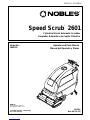 1
1
-
 2
2
-
 3
3
-
 4
4
-
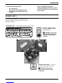 5
5
-
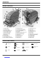 6
6
-
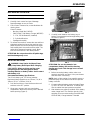 7
7
-
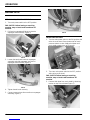 8
8
-
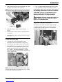 9
9
-
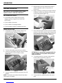 10
10
-
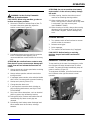 11
11
-
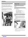 12
12
-
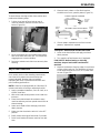 13
13
-
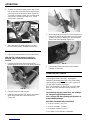 14
14
-
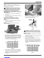 15
15
-
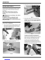 16
16
-
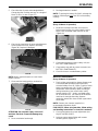 17
17
-
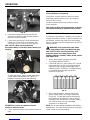 18
18
-
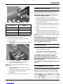 19
19
-
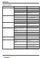 20
20
-
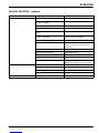 21
21
-
 22
22
-
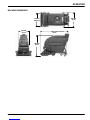 23
23
-
 24
24
-
 25
25
-
 26
26
-
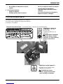 27
27
-
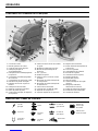 28
28
-
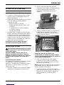 29
29
-
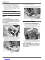 30
30
-
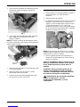 31
31
-
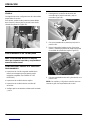 32
32
-
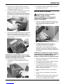 33
33
-
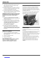 34
34
-
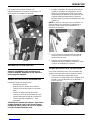 35
35
-
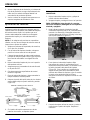 36
36
-
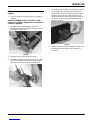 37
37
-
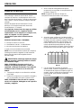 38
38
-
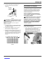 39
39
-
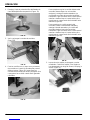 40
40
-
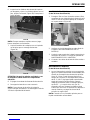 41
41
-
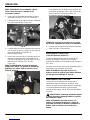 42
42
-
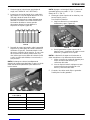 43
43
-
 44
44
-
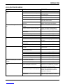 45
45
-
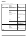 46
46
-
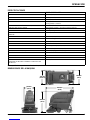 47
47
-
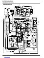 48
48
-
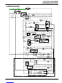 49
49
-
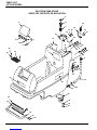 50
50
-
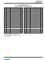 51
51
-
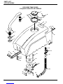 52
52
-
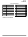 53
53
-
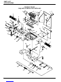 54
54
-
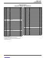 55
55
-
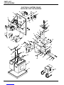 56
56
-
 57
57
-
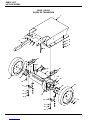 58
58
-
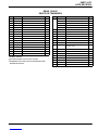 59
59
-
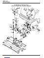 60
60
-
 61
61
-
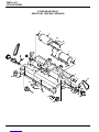 62
62
-
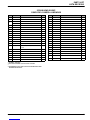 63
63
-
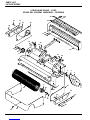 64
64
-
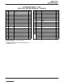 65
65
-
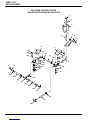 66
66
-
 67
67
-
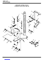 68
68
-
 69
69
-
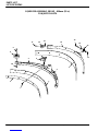 70
70
-
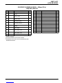 71
71
-
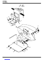 72
72
-
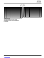 73
73
-
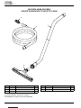 74
74
-
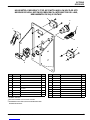 75
75


Nobles Speed Scrub 2601 Operator And Parts Manual
- Categoría
- Máquina de piso
- Tipo
- Operator And Parts Manual