
Reference Manual
EN

2
PX10/PX8/PX5/PX3 Reference Manual
Contents
Introduction 3
Features ....................................................................3
Manuals for PX amplifier ...........................................3
Usage examples .......................................................4
Use with two full-range speakers .........................4
Use with a full-range speaker and subwoofer......4
Use with a full-range speaker
driven in bi-amp mode ......................................5
Use for driving a subwoofer with a stereo signal
...5
PX amplifier available system configurations.......6
Signal processing in PX amplifier ........................7
Input sensitivity and amplifier gain .......................7
Controls and functions 8
Front panel ................................................................8
Rear panel.................................................................9
Setup 10
Setup procedure......................................................10
Rack mounting ........................................................11
Speaker connection ................................................11
Connecting to the [SPEAKERS] terminal...........11
Panel Operation 12
Basic operation .......................................................12
Basic mode and Advanced mode ......................12
Screen structure......................................................13
Alert messages .......................................................14
Panel lock................................................................14
HOME screen..........................................................15
CONFIG VIEW screen ........................................... 16
MENU screen ......................................................... 17
MENU screen types .......................................... 17
Operation .......................................................... 17
Operation tree ................................................... 18
CONFIG WIZARD screen (Basic mode) ................ 20
SP TYPE (speaker type) ................................... 20
SP SERIES (speaker series) ............................ 20
SP MODEL (speaker model)............................. 20
HPF (high pass filter) ........................................ 21
LPF (low pass filter) .......................................... 21
X-OVER (crossover) ......................................... 21
CONFIRMATION .............................................. 21
CONFIG WIZARD screen (Advanced mode) ......... 22
WIZARD MODE ................................................ 22
SP TYPE (speaker type) ................................... 22
ROUTING.......................................................... 23
SENS./GAIN (input sensitivity/amplifier gain) ... 24
SP SERIES (speaker series) ............................ 24
SP MODEL (speaker model)............................. 24
SP IMPEDANCE (speaker impedance) ............ 24
CONFIRMATION .............................................. 24
TUNING screen...................................................... 25
D-CONTOUR .................................................... 25
DELAY .............................................................. 26
X-OVER (crossover) ......................................... 26
HPF (high pass filter) ........................................ 27
LPF (low pass filter) .......................................... 27
POLARITY (speaker polarity)............................ 28
SP DELAY......................................................... 28
EQ (6 Band PEQ).............................................. 29
LEVEL (output level) ......................................... 29
LIMITER ............................................................ 30
CHANNEL LINK ................................................ 30
CHANNEL COPY .............................................. 30
SAVE/LOAD ...................................................... 31
AMP PRESET screen............................................. 32
RECALL ............................................................ 32
STORE .............................................................. 32
CLEAR .............................................................. 32
TITLE................................................................. 33
PROTECT ......................................................... 33
UTILITY screen ...................................................... 34
PANEL SETUP.................................................. 34
PANEL LOCK.................................................... 34
HOME SCREEN (HOME screen)...................... 35
IMPORT SP PRESET
(import speaker preset) ................................. 35
DEVICE BACKUP ............................................. 36
DEVICE INFORMATION ................................... 36
INITIALIZE......................................................... 36
LOG................................................................... 37
Initializing the PX amplifier ..................................... 37
Reference 39
Function list ............................................................ 39
Message list............................................................ 42
Troubleshooting...................................................... 44
General specifications ............................................ 46
Block diagram......................................................... 48
Dimensions............................................................. 49
Current draw and thermal dissipation..................... 50
Index....................................................................... 54

3
PX10/PX8/PX5/PX3 Reference Manual
Introduction
Thank you for your purchase of the Yamaha PX10, PX8, PX5 or PX3 power amplifier. Please read through this manual carefully before using for the first time,
in order to take full advantage of your PX power amplifier’s superlative features and enjoy trouble-free operation for years to come.
• Please read the Precautions in the PX10/PX8/PX5/PX3 Owner’s Manual before use.
• The illustrations as shown in this manual are for instructional purposes only.
• The company names and product names used in this manual are the trademarks or registered trademarks of their respective companies.
• In this manual, the PX10, PX8, PX5 and PX3 power amplifier models are referred to collectively as “PX amplifier.”
• Unless specified otherwise, the example illustrations used in this manual are taken from the PX10.
• The bitmap fonts used in this instrument have been provided by and are the property of Ricoh Co., Ltd.
• Maximum output of 1,000W (PX10), from an exceptionally lightweight chassis.
• Yamaha’s proprietary Class-D and processing technologies provide superb sound qual-
ity and high reliability.
• Speaker presets that allow you to get the best possible performance from Yamaha
speakers.
• A wide variety of DSP functions, including D-CONTOUR processing.
• Configuration Wizard that allows easy, optimal configuration for any speaker system.
• Broad range of input/output connectors.
• Owner’s Manual (included with the product)
Explains installation and basic operation.
• Reference Manual (this file)
Explains all required matters for setup and operation.
• Technical Specifications (included with the product)
Describes detailed specifications such as numerical values, dimensions, etc.
Features Manuals for PX amplifier

Introduction — Usage examples
4
PX10/PX8/PX5/PX3 Reference Manual
PX amplifiers can be used for various applications.
Use with two full-range speakers
This conventional application inputs stereo L/R signals to each channel (A/B) for stereo reproduction with two speakers.
Use with a full-range speaker and subwoofer
The input signal is divided into separate frequency ranges for driving a full-range speaker and subwoofer.
Usage examples

Introduction — Usage examples
5
PX10/PX8/PX5/PX3 Reference Manual
Use with a full-range speaker driven in bi-amp mode
The input signal is divided into separate frequency ranges for driving a two-way full-range speaker in bi-amp mode.
Use for driving a subwoofer with a stereo signal
Stereo input signals drive a subwoofer in Power Boost mode (PX5 and PX3 only)
Channel A + Channel B
(PX5)

Introduction — Usage examples
6
PX10/PX8/PX5/PX3 Reference Manual
PX amplifier available system configurations
PX amplifier can be used with the following 15 types of system configurations, including the examples above.
Input configuration (routing)
Dual mode Parallel mode Single mode Sum mode
Channel A and channel B are
independent.
After dividing channel A input
signal to channel A and channel B,
the signal is processed.
After processing channel A input
signal, the signal is divided to A and
channel B.
Mixes input signals from
channel A and channel B.
Two full-range speakers
Two subwoofers
A full-range speaker and a subwoofer
A full-range speaker
driven in bi-amp mode
Full-range speaker
Power Boost
mode
Subwoofer
NOTE
In Power Boost mode, the two-channel amplifiers are used as one-channel, high-power amplifier (PX5 and PX3 only).
Output combination (speaker type)

Introduction — Usage examples
7
PX10/PX8/PX5/PX3 Reference Manual
Signal processing in PX amplifier
The PX amplifier gives you comprehensive control over the sound with input processors and speaker processors. The signals from the input connectors are processed in input processors
equipped in each input connectors. The processed signals are added or divided depending on the set routing, processed finally with the speaker processor in each channel, and output from the
[SPEAKERS] terminals.
Refer to “TUNING screen” (page 25) in “Panel Operation” for details on the processing.
Input sensitivity and amplifier gain
The PX amplifier specifies the input sensitivity/amplifier gain from two input sensitivities or two amplifier gains. Input sensitivity controls the input signal level so that the amplifier can output
the maximum power. If signals over the input sensitivity are input, the built-in limiter of the PX amplifier is activated. If the volume is lowered, the input sensitivity rises and the amplifier gain
declines. Maximum power is constant if the volume is lowered.
For example, if the amplifier gain on the PX10 is set to 32 dB, the input sensitivity is +9.3 dBu and the maximum output power is 1,000 W (if speaker impedance is 8Ω). When the volume is not
lowered (0 dB), output power of 1,000 W results with +9.3 dBu input.
When the volume on the PX10 is lowered to 6 dB, the input sensitivity is +15.3 dBu (9.3 dBu + 6 dBu) and the amplifier gain is 26 dB (32 dB - 6 dB). If a +15.3 dBu signal is input, maximum
output power of 1,000 W is gained.
D-Contour
Delay
HPF LPF Polarity
Speaker
Delay
Level Limiter
6 Band
PEQ
Input processor Speaker processor
Amplifier gain 26 dB
Volume 6 dB
Amplifier gain 32 dB
Maximum output power 41.3 dBu
(1000 W, 8Ω)
Input sensitivity +15.3 dBu
Input sensitivity +9.3 dBu

8
PX10/PX8/PX5/PX3 Reference Manual
Controls and functions
q Power button
Turns the power to the unit on or off.
w [POWER] indicator
Lights when the power is on.
e [ALERT] indicator
Lights when a problem in the device is detected, and contin-
ues to light until the cause of the problem is solved.
r [USB] indicator
Lights when a compatible USB flash drive is inserted into the
[USB] terminal.
Flashes when the USB flash drive is being accessed.
t [CLIP/LIMIT] indicator
Lights when the limiter is operating to protect the amplifier and
the speaker, or when the input signal overflows in the digital
circuit or clips at the amplifier output.
y [SIGNAL] indicator
Lights when the output is greater than -60 dB of maximum
output level (8 ohms).
u [PROTECT] indicator
Lights when the protection circuit is operating.
i Display
Displays the status of the PX amplifier and setting menus.
For details, refer to “Screen structure” (page 13).
o [MENU] key
Press this to move to the top MENU screen.
!0 [] (Back) key
Press this to move up to the immediately higher menu level or
previous display. Press and briefly hold the key to return the
HOME screen.
!1 Main knob
Rotate this to change the value of parameters and move the
position of cursor. Press the knob to actually enter the set
value or enable the selected item.
!2 [A]/[B] key
Press this to change the values of parameters and move the
cursor position.
!3 [USB] terminal
Insert a USB flash drive to read/load the data from/to the PX
amplifier.
!4 Volume knob
Adjusts the level from -∞ dB to 0 dB.
If “ROUTING” is set to something other than “DUAL,” adjust
the output balance with the volume knob of channel B.
!5 Intake ports
Air intakes for the cooling fan. Make sure to not block these ports.
Front panel
e
r
w
t
y
u
i
t
y
u
!2 !2
o !0
!1
!4
!5 !5
!4
!3
q
WARNING
To ensure that high-volume noise is not output from the
speakers, power-on the equipment starting with the audio
sources, then the mixer and processors, and finally the
amplifiers. Reverse this order when turning the system off.
NOTE
Details of the problem are shown on the display (i).
Selecting the [ ] icon on the “HOME screen” (page 15) with the
main knob calls up the operating log.
NOTICE
Do not unplug the USB flash drive while the [USB] indicator is
flashing. Doing so may cause data in the PX amplifier or USB
flash drive to be corrupted or lost.
NOTE
• The settings can be changed so that the display and indicators
turn off automatically when panel is not operated (Black-out sta-
tus: page 34).
• For protection of the display, if there is no operation for one min-
ute, the display automatically darkens; if unoperated for 20 min-
utes, it automatically turns off. To turn on the display again,
simply press any key on the front panel or rotate any knob.
NOTE
Press the main knob and [A] key to change the mute status of
channel A. Press the main knob and [B] key to change the mute
status of channel B.
NOTICE
When the [USB] terminal is not used, attach the included USB cap
to protect the terminal.
NOTE
The [USB] terminal is used in the following cases:
• Loading speaker preset: IMPORT SP PRESET (page 35)
• Writing operation log: LOG (page 37)
• Device backup: DEVICE BACKUP (page 36)
• Saving/loading SP TUNING DATA: SAVE/LOAD (page 31)

Controls and functions — Rear panel
9
PX10/PX8/PX5/PX3 Reference Manual
!6 [INPUT] A/B connectors
Two types of input connectors are provided for both channels
A and B. In Single mode or Parallel mode, the input connec-
tors of channel A are used.
• XLR jack
XLR type 3-31 jack.
The polarity is shown below (IEC60268).
• Phone jack
Balanced TRS phone jack.
The polarity of the connections is shown below.
!7 [SPEAKERS] A/B terminals
Output terminals for speakers. Three types are available
(below).
• Neutrik NL4MD speakON connector
• Binding post connector
• Phone jack
!8 [AC IN] connector
Connect the supplied AC power cord. First connect the AC
power cord to the connector on the amplifier, and then plug it
into an appropriate AC power outlet. Secure the AC power
cord with the AC plug clamp to prevent accidental disconnec-
tion from the connector.
!9 Exhaust ports
Exhaust vents for the cooling fan. Make sure to not block
these ports.
Rear panel
!7
!8!6
!9
NOTE
The XLR input jack and the phones input jack of each channel are
connected in parallel. The signal input from an XLR jack can be
output from the phone jack and input to another amplifier. Only
one of the jacks can be used as an input jack at one time; the sig-
nals from the jacks cannot be mixed.
12
3
Ground
Cold
Hot
Ring (cold)
Tip (hot)Sleeve (ground)
NOTICE
• Do not touch the terminals or metal parts of cords connected to
the terminal. If connecting speakers to multiple connectors of
the same channel results in a parallel connection, make sure
that the total impedance of the speakers to be connected is not
excessively low.
• The PX amplifier adopts BTL (Balanced Transformer Less)
amplifier circuits. Connecting both terminals of channel A and
channel B and contact between the terminal and the chassis
may cause a failure or malfunction. Be careful not to connect or
contact the two by mistake.
NOTE
In Power Boost mode, the output terminals of channel A are used
(PX5/PX3 only).
qwe
Installing the AC plug clamp

10
PX10/PX8/PX5/PX3 Reference Manual
Setup
1. Set the PX amplifier in the desired loca-
tion.
If the device is to be mounted in a rack, refer to “Rack
mounting” (page 11).
2. Lower the two volume knobs to the mini-
mum.
3. Connect speakers to the [SPEAKERS]
terminals.
Refer to “Speaker connection” (page 11).
4. Connect outputs from sources, such as
a mixer, to the [INPUT] connectors.
5. Connect the power cord to the [AC IN]
connector.
Secure the AC power cord with the AC plug clamp to
prevent accidental disconnection from the connector.
6. Turn on the device.
7. Set up the system configuration with the
Configuration Wizard.
Though the PX amplifier can be used as a normal ampli-
fier by simply setting the volume knobs properly, using
the Configuration Wizard to make settings enhances the
performance of speakers.
Refer to “CONFIG WIZARD screen (Basic mode)”
(page 20) or “CONFIG WIZARD screen (Advanced
mode)” (page 22).
8. Rotate the volume knob to adjust the vol-
ume.
9. Control the tone in TUNING screen.
Refer to “TUNING screen” (page 25). In this condition,
the device is available.
Setup procedure
WARNING
To ensure that high-volume noise is not output from the
speakers, power-on the equipment starting with the
audio sources, then the mixer and processors, and
finally the amplifiers. Reverse this order when turning
the system off.
To A C p o w e r
outlet
Power cord
AC IN connector
Installing the AC plug clamp
qwe

Setup — Rack mounting
11
PX10/PX8/PX5/PX3 Reference Manual
The PX amplifier can be mounted in an EIA standard rack
(2U size).
Rack mounting
Precautions for rack mounting
This device is rated for operation at ambient tempera-
tures ranging from 0° to 40°C. When mounting the device
with other device(s) in an EIA standard equipment rack,
internal temperatures can exceed the specified upper
limit, resulting in impaired performance or failure. When
rack mounting the device, always observe the following
requirements to avoid heat buildup:
• When mounting the unit in a rack with devices such as
power amplifiers that generate a significant amount of
heat, leave more than 1U of space between the device
and other equipment. Also, either leave the open
spaces uncovered or install appropriate ventilating pan-
els to minimize the possibility of heat buildup. Multiple
PX amplifiers can be mounted by stacking vertically.
• To ensure sufficient airflow, leave the rear of the rack
open and position it at least 10 centimeters from walls
or other surfaces. If the rear of the rack cannot be left
open, install a commercially available fan or similar ven-
tilating option to secure sufficient airflow. If you have
installed a fan kit, there may be cases in which closing
the rear of the rack will produce a greater cooling effect.
Refer to the rack and/or fan unit manual for details.
Connecting to the [SPEAKERS] termi-
nal
Binding post connector
• Without plugs
Remove about 15 mm of insulation from the end of
each speaker cable, pass the bare wire through the holes
in the appropriate speaker terminals, and tighten the ter-
minals to securely clamp the wires. Make sure that the
bare wire ends do not jut out from the terminals and
touch the chassis.
• Y-plugs
From above, insert the Y-plugs all the way into the
opening, and tighten the terminal.
speakON connector
Insert the speakON cable plug (Neutrik NL4) into the
connector, and turn it to the right to lock it.
Speaker connection
CAUTION
Make sure that the power is turned off, to avoid the dan-
ger of electrical shock.
15 mm
0.25"
(6.3 mm)
≤0.51"
(12.9 mm)
1+
1–
2–
2+
Channel A
Neutrik NL4 PX amplifier
1+ A+
1– A–
2+ B+
2– B–
Channel B
Neutrik NL4 PX amplifier
1+ B+
1– B–
2+ (not connected)
2– (not connected)

12
PX10/PX8/PX5/PX3 Reference Manual
Panel Operation
Basic mode and Advanced mode
The PX amplifier provides two setting methods: Basic mode and Advanced mode.
Basic mode is convenient since it lets you use the device quickly and easily with minimum
settings. Advanced mode is used when you want to set parameters in detail.
Each mode has a HOME screen and MENU screen.
Example of screens
To switch between Basic mode and Advanced mode
1. Press the [MENU] key to enter the MENU screen.
2. Rotate the main knob to select the tab of the desired mode, and
then press the main knob.
Basic operation
HOME screen (Basic mode) MENU screen (Advanced mode)
• BASIC:
Basic mode
• ADVANCED:
Advanced mode

Panel Operation — Screen structure
13
PX10/PX8/PX5/PX3 Reference Manual
The screens of the PX amplifier differ depending on the selected mode, Basic or Advanced. The HOME screen and the CONFIG WIZARD screen in the MENU screen are in both modes, but dis-
played items differ. To switch between the modes, use the OPERATION MODE screen in the MENU screen.
Screen structure
Basic mode
HOME screen
CONFIG VIEW screen
MENU screen
MENU top screen
CONFIG WIZARD screen
TUNING screen
AMP PRESET screen
UTILITY screen
Advanced mode
HOME screen
CONFIG VIEW screen
MENU top screen
CONFIG WIZARD screen
TUNING screen
AMP PRESET screen
UTILITY screen
MENU screen
BASIC
ADVANCED

Panel Operation — Alert messages
14
PX10/PX8/PX5/PX3 Reference Manual
If an abnormality occurs in the PX amplifier, the [ALERT] indicator lights and an alert mes-
sage appear on the display. Refer to the “Message list” (page 42) at the end of the book for
details on each alert.
To prevent changes being made to the PX amplifier by mistake, use the panel lock function.
This allows you to set a PIN code (a 4-digit identification number).
Refer to “UTILITY screen” – “PANEL LOCK” (page 34) for instructions.
To release the panel lock
If the panel controls are operated while the panel is locked, the following message appears
in the display.
To release the panel lock, input the PIN code by rotating the main knob, select “OK,” and
then press the main knob.
Alert messages Panel lock
NOTE
• To release the panel lock temporarily, select “TEMP.” If “TEMP” is selected, the panel will be
locked after turning off and turning on again.
• If a PIN code has been set, input the appropriate PIN code (set previously).
NOTE
If the volume knob is operated when the panel is locked with “ALL,” the following screen appears when
the lock is released. Rotate the volume knob to match the actual value. The value of the volume can-
not be changed unless the values match.
Actual value Value of the volume

Panel Operation — HOME screen
15
PX10/PX8/PX5/PX3 Reference Manual
q Mute indication
Appears when the signal is muted.
w Volume indication
Shows the settings of the volume knobs.
In Power Boost mode, only channel A setting is shown.
e VOL/BAL/GAIN indication
Shows what appears at the volume indications (w).
•VOL: Input volume
•BAL: Output balance
•GAIN: Total level (gain from the input jack to the speaker output terminal)
r Level meter
Shows input or output level.
t Threshold indication
Indicates the thresholds of the limiter on the output level of the speaker processors with
“>” and “<” while the level meter shows the input level.
y D-CONTOUR indication
Shows the status of D-CONTOUR.
•OFF: Nothing appears.
• FOH/MAIN: “FOH” appears.
• MONITOR: “MONI” appears.
u Delay indication
Shows the delay time. When delay is off, nothing appears.
i Polarity indication
Appears when the polarity is inverted.
o Filter indication
Shows the cutoff frequency of the filter. When the filter is off, nothing appears.
!0 EQ indication
Appears when the EQ is on.
!1 CONFIG VIEW icon
CONFIG VIEW screen appears when selecting the icon by rotating the main knob and
pressing it.
!2 [ ] icon
Operation log appears when selecting the icon by rotating the main knob and pressing it.
Refer to “Operation log indication” (page 37) for details on the operation log.
!3 Speaker name, clipping/limiting message
Normally, this shows the name of the speaker that is connected, along with a related mes-
sage if clipping or limiting has occurred.
HOME screen
NOTE
Displayed content depends on the input configuration (routing).
• In Dual mode: Input volume at both channels A and B.
• Other than Dual mode: Input volume at channel A, output balance at channel B.
(In Power Boost mode, only channel A is shown.)
Set at “dB VALUE” (page 35) in UTILITY screen–HOME SCREEN screen, which is shown in VOL/
BAL/GAIN indication, input volume or total gain.
NOTE
Input and output can be switched from [HOME SCREEN] (page 35) in the UTILITY screen.
r
!3
y
t
q
e
w
!1o i o u !2!0
NOTE
The displayed speaker name is the speaker preset recalled with the Configuration Wizard.
NOTE
Rotate the main knob to select the group of D-CONTOUR, delay, polarity and filter indications, and
then press the main knob to call up the TUNING screen.

Panel Operation — CONFIG VIEW screen
16
PX10/PX8/PX5/PX3 Reference Manual
Called up by pressing the main knob when the HOME screen is shown.
The current settings are listed.
q System configuration: page 6
w Input sensitivity/amplifier gain: page 24
e HPF cutoff frequency for channel A: pages21, 27
r LPF cutoff frequency for channel A: pages21, 27
t HPF cutoff frequency for channel B: pages21, 27
y LPF cutoff frequency for channel B: pages21, 27
u System configuration: page 6
i Input sensitivity/amplifier gain: page 24
o HPF cutoff frequency for channel A: pages21, 27
!0 Crossover frequency: pages21, 26
!1 LPF cutoff frequency for channel B: pages21, 27
!2 Polarity: page 28
To return to the HOME screen, press the [ ] (back) key.
To call up the CONFIG WIZARD screen, press the main knob when the CONFIG VIEW
screen appears.
CONFIG VIEW screen
q
w
e r
ty
u
i
o !0 !1
!2

Panel Operation — MENU screen
17
PX10/PX8/PX5/PX3 Reference Manual
Sets the basic condition of the device.
MENU screen types
The following MENU screens are available.
• CONFIG WIZARD screen (Basic mode) (Advanced mode)
• TUNING screen
• AMP PRESET screen
• UTILITY screen
Operation
To display the MENU screen:
Press the [MENU] key in the HOME screen.
To move to the lower layer in MENU screens, or to select a param-
eter or other item:
Rotate the main knob to move to the desired item, and then press the main knob.
To move to the upper layer in MENU screens:
Press the [ ] (back) key.
To return to the HOME screen:
Press and hold the [ ] (back) key.
MENU screen
NOTE
Refer to the “Function list” (page 39) for details on configurable items in each MENU screen.
NOTE
The layer of the displayed screen is shown at the top of the screen.
MENU top screen HPF screen
Parameter edit screenTUNING screen

Panel Operation — MENU screen
18
PX10/PX8/PX5/PX3 Reference Manual
Operation tree
Category Subcategory Function
Basic
mode
Advanced
mode
Details
CONFIG WIZARD
(Basic mode)
SP TYPE Selects a combination of speakers for connection. page 20
SP SERIES Selects a series of speakers for connection. page 20
SP MODEL Selects a speaker for connection. page 20
HPF Selects the cutoff frequency of the HPF. Common to channels A and B. page 21
LPF Selects a cutoff frequency of the LPF. Common to channels A and B. page 21
X-OVER Selects a crossover frequency of the full-range speaker and the subwoofer. page 21
CONFIRMATION Applies the set value. page 21
CONFIG WIZARD
(Advanced mode)
WIZARD MODE Selects the editing method: changing the current setting or making a new setting. page 22
SP TYPE Selects a combination of speakers for connection. page 22
ROUTING Selects the route of the input signal. page 23
SENS./GAIN Sets the input sensitivity or the amplifier gain. page 24
SP SERIES Selects a series of speakers for connection. page 24
SP MODEL Selects a speaker for connection. page 24
SP IMPEDANCE Sets the impedance of the speaker for connection. page 24
CONFIRMATION Applies the set value. page 24
TUNING
D-CONTOUR Sets the frequency character appropriately for usage of the speaker for connection. page 25
DELAY Sets the delay time to compensate the distance between speakers. page 26
X-OVER Sets the crossover frequency. page 26
HPF Sets the high pass filter. * page 27
LPF Sets the low pass filter * page 27
POLARITY Set the polarity. page 28
SP DELAY Sets the delay time of the speaker processor. page 28
EQ Edits 6 Band PEQ settings. page 29
LEVEL Sets the output level. page 29
LIMITER Sets the limiter. page 30
CHANNEL LINK Links the parameter setting of channels A and B. page 30
CHANNEL COPY Copies settings between channels. page 30
SAVE/LOAD Saves or loads SP TUNING DATA via a USB flash drive. page 31
* Only for some functions.

Panel Operation — MENU screen
19
PX10/PX8/PX5/PX3 Reference Manual
AMP PRESET
RECALL Recalls a setting. page 32
STORE Stores the setting. page 32
CLEAR Clears the setting. page 32
TITLE Edits the title of the setting. page 33
PROTECT Protects the setting against inadvertent changes. page 33
UTILITY
PANEL SETUP Sets the front panel indication method. * page 34
PANEL LOCK Sets the panel lock. page 34
HOME SCREEN Sets contents of the HOME screen. page 35
IMPORT SP PRESET Loads speaker preset data stored in the USB flash drive to the PX amplifier. page 35
DEVICE BACKUP Stores all the settings of the PX amplifier or restore the stored settings. page 36
DEVICE INFORMATION Displays the condition in the device. page 36
INITIALIZE Displays how to initialize the data in the PX amplifier on the display. page 36
LOG Displays or writes the operating log. page 37
* Only for some functions.
Category Subcategory Function
Basic
mode
Advanced
mode
Details

Panel Operation — CONFIG WIZARD screen (Basic mode)
20
PX10/PX8/PX5/PX3 Reference Manual
Using the Configuration Wizard enables you to easily set basic functions.
SP TYPE (speaker type)
Selects the combination of the speakers for connection.
• FULL + FULL:
When connecting full-range speakers to the [SPEAKERS] terminals of both channels A
and B.
• SUB + SUB:
When connecting subwoofers to the [SPEAKERS] terminals of both channels A and B.
• FULL + SUB:
When connecting a full-range speaker to the [SPEAKER] terminal of channel B and a
subwoofer to the [SPEAKER] terminal of channel A.
SP SERIES (speaker series)
Selects a speaker series for connection from models registered in the PX amplifier.
SP MODEL (speaker model)
Specifies a speaker for connection from the speaker series selected in the SP SERIES
screen.
CONFIG WIZARD screen (Basic mode)
WARNING
The volume changes depending on the setting. Carry this out with the volume lowered for
safety.
NOTE
Items that can be set differ between Basic mode and Advanced mode. To make detailed settings,
switch to Advanced mode. Refer to “To switch between Basic mode and Advanced mode” (page 12)
for switching the mode.
NOTE
When a speaker is selected, filters, speaker impedance, and threshold of the limiter are set auto-
matically. If the speaker for connection is not in the menu, select “GENERIC.”

Panel Operation — CONFIG WIZARD screen (Basic mode)
21
PX10/PX8/PX5/PX3 Reference Manual
HPF (high pass filter)
(If “SP SERIES” is “GENERIC”)
Selects the cutoff frequency of the HPF. Common to both channels A and B.
LPF (low pass filter)
(If “AMP MODE” is “SUB+SUB” and “SP SERIES” is “GENERIC”)
Selects the cutoff frequency of the LPF. Common to both channels A and B.
X-OVER (crossover)
(If “AMP MODE” is “FULL+SUB” and “SP SERIES” is “GENERIC”)
Selects the crossover frequency of the full-range speaker and subwoofer.
CONFIRMATION
Applies the set value.
After confirming the setting is appropriate, press the main knob to actually apply the set
value.
To correct the setting, press the [ ] (back) key to return to the screen to be corrected.
To cancel the setting, press the [MENU] key or press and hold the [ ] (back) key until a
confirmation screen appears.
NOTE
In Basic mode, the filter type is fixed to 24 dB/Oct., Butterworth type.
NOTE
In Basic mode, the filter type is fixed to 24 dB/Oct., Butterworth type.
NOTE
In Basic mode, the filter type is fixed to 24 dB/Oct., Linkwitz Riley type.

Panel Operation — CONFIG WIZARD screen (Advanced mode)
22
PX10/PX8/PX5/PX3 Reference Manual
Using the Configuration Wizard here enables you to easily set more advanced functions.
WIZARD MODE
Select a parameter status to start settings.
• EDIT CONFIG:
Changing the current setting
• NEW CONFIG:
Making a new setting
SP TYPE (speaker type)
Selects a combination of speakers for connection.
• FULL+FULL:
When connecting full-range speakers to the [SPEAKERS] terminals of both channels A
and B.
• SUB+SUB:
When connecting subwoofers to the [SPEAKERS] terminals of both channels A and B.
• FULL+SUB:
When connecting a full-range speaker to the [SPEAKERS] of channel B and a subwoofer
to channel A.
•BI-AMP:
When connecting low range of a bi-amp speaker to the [SPEAKERS] of channel A and
high range to channel B.
• FULL (MONO):
When connecting a full-range speaker driven in Power Boost mode to the [SPEAKERS]
terminal of channel A (PX5 and PX3 only).
• SUB (MONO):
When connecting a subwoofer driven in Power Boost mode to the [SPEAKERS] terminal
of channel A (PX5 and PX3 only).
CONFIG WIZARD screen (Advanced mode)
WARNING
The volume changes depending on the setting. Carry this out with the volume lowered for
safety.
NOTE
To return to a previous parameter setting, press the [ ] (back) key.
NOTE
Refer to “PX amplifier available system configurations” (page 6) for details on combinations listed
in “ROUTING” (page 23).

Panel Operation — CONFIG WIZARD screen (Advanced mode)
23
PX10/PX8/PX5/PX3 Reference Manual
ROUTING
Selects the route of the input signal from four types: DUAL, PARALLEL, SINGLE, and
SUM.
• DUAL (Dual mode):
Sends the input signal from channel A to speaker A, and sends the input signal from
channel B to speaker B.
• PARALLEL (Parallel mode):
Sends the input signal from channel A to both speaker A and speaker B. Channel A and
channel B can be set differently.
• SINGLE (Single mode):
Sends only the input signal from channel A.
• SUM (Sum mode):
Mixes and sends the input signals from channel A and channel B.
[SPEAKERS] A
[SPEAKERS] B
[INPUT] A
[INPUT] B
VOL
VOL
Input
processor A
Speaker
processor A
Input
processor B
Speaker
processor B
[INPUT] A
[INPUT] B
Input
processor A
Speaker
processor A
Input
processor B
Speaker
processor B
VOL
BAL
[SPEAKERS] A
[SPEAKERS] B
NOTE
The volume knob is available only for control of channel A. The volume of channel B is linked to
that of channel A.
NOTE
• Depending on the SP TYPE (speaker type, page 22), the menu choices may be limited. For
details, refer to “PX amplifier available system configurations” (page 6).
• Regarding input processors and speaker processors, refer to “Signal processing in PX amplifier”
(page 7). For setting instructions, refer to “TUNING screen” (page 25).
[INPUT] A
[INPUT] B
Input
processor A
Speaker
processor A
Speaker
processor B
VOL
BAL
[SPEAKERS] A
[SPEAKERS] B
[INPUT] A
[INPUT] B
Input
processor A
Speaker
processor A
Input
processor B
Speaker
processor B
BAL
[SPEAKERS] A
[SPEAKERS] B
VOL

Panel Operation — CONFIG WIZARD screen (Advanced mode)
24
PX10/PX8/PX5/PX3 Reference Manual
SENS./GAIN (input sensitivity/amplifier gain)
Sets the input sensitivity or the amplifier gain.
You can select the input sensitivity(+4 dBu or +14 dBu), or the amplifier gain (26 dB or 32
dB).
SP SERIES (speaker series)
Selects a speaker series for connection from models registered in the PX amplifier.
SP MODEL (speaker model)
Specifies a speaker for connection from the speaker series selected in SP SERIES screen.
SP IMPEDANCE (speaker impedance)
(If “SP SERIES” is “GENERIC”)
Sets the impedance of the speaker for connection.
When connecting speakers in parallel, set this parameter by a single speaker's impedance.
CONFIRMATION
Applies the set value.
After confirming the setting is appropriate, press the main knob to actually apply the set
value.
To change or correct the setting, press the [ ] (back) key to return to the previous screen.
To cancel the setting, press the [MENU] key or press and hold the [ ] (back) key until a
confirmation screen appears.
NOTE
Refer to “Input sensitivity and amplifier gain” (page 7) for details on input sensitivity and amplifier
gain.
NOTE
When a speaker is selected, filters, speaker impedance, and threshold of the limiter are set auto-
matically. If the speaker for connection is not in the menu, select “GENERIC.”

Panel Operation — TUNING screen
25
PX10/PX8/PX5/PX3 Reference Manual
Set input processors and speaker processors for acoustic adjustment.
D-CONTOUR
Sets the frequency character appropriately for usage of the speaker for connection.
q MODE
Switches presets of D-CONTOUR. Selects from the following items:
•OFF:
Turns off D-CONTOUR.
• FOH/MAIN:
Boosts the high and low frequency components so that the frequency response is suit-
able for main speaker use.
• MONITOR:
Reduces the low frequency range, which could otherwise tend to be boomy if the
speaker is set directly on the floor. This enables you to hear mid and high frequency
ranges clearly when using as a floor monitor.
w DEPTH
Sets the degree of the effect. The larger the value, the deeper the effect.
TUNING screen
NOTE
• If “A” or “B” appears in a parameter setting screen at the upper side in TUNING screen, the parame-
ter is for the respective channel, A or B.
• Press the [A] key or [B] key to select the desired channel for setting.
D-Contour
HPF LPF Polarity Level Limiter
6 Band
PEQ
Delay
Speaker
Delay
Channel
Input processor and speaker processor
Input processor Speaker processor
q
w
D-Contour
HPF LPF Polarity Level Limiter
6 Band
PEQ
Delay
Speaker
Delay
Channel
Input processor Speaker processor

Panel Operation — TUNING screen
26
PX10/PX8/PX5/PX3 Reference Manual
DELAY
(Advanced mode only)
Sets the delay time to compensate the distance between speakers. Sets according to ether
time or distance.
q ON/OFF
Turns the delay on/off.
w TIME [ms]
Sets the delay time in milliseconds.
e DISTANCE [m / feet]
Sets the delay time by physical distance (in meters or in feet).
X-OVER (crossover)
(If “SP TYPE” is “FULL+SUB” or “BI-AMP”)
Sets the crossover frequency of channel A and channel B.
q X-OVER FREQ.
Sets the crossover frequency. The crossover frequency to be set is the cutoff frequencies
of the LPF of channel A and the HPF of channel B.
NOTE
Three delay time indications change in conjunction.
D-Contour
HPF LPF Polarity Level Limiter
6 Band
PEQ
Delay
Speaker
Delay
q
e
w
Channel
Input processor Speaker processor
D-Contour
HPF LPF Polarity Level Limiter
6 Band
PEQ
Delay
Speaker
Delay
q
Channel
Input processor Speaker processor
Low pass filter High pass filterCrossover frequency
Frequency

Panel Operation — TUNING screen
27
PX10/PX8/PX5/PX3 Reference Manual
HPF (high pass filter)
Sets the high pass filter.
q ON/OFF
(Basic mode only)
Turn on/off the filter.
w TYPE (filter type)
(Advanced mode only)
Selects the attenuation per octave and the filter type.
e FREQ (Cutoff frequency)
Sets the cutoff frequency of the HPF.
r Gc (Cutoff gain)
(Advanced mode only)
Sets the gain at the cutoff frequency if “AdjustGc” (Adjustable Gc) is selected in “HPF
TYPE.”
LPF (low pass filter)
Sets the low pass filter.
q ON/OFF
(Basic mode only)
Turns the filter on/off.
w TYPE (filter type)
(Advanced mode only)
Selects the attenuation per octave and the filter type.
e FREQ (Cutoff frequency)
Sets the cutoff frequency of the LPF.
r Gc (Cutoff gain)
(Advanced mode only)
Sets the gain at the cutoff frequency if “AdjustGc” (Adjustable Gc) is selected in “LPF
TYPE.”
NOTE
• If “THRU” is selected, filter is off.
• A filter on 12 db/Oct or more can be selected from four types (below): Adjustable Gain Con-
trol, Butterworth, Bessel, and Linkwitz Riley.
For example, the 12 dB/Oct. Butterworth type is displayed as “12dB BUT.”
D-Contour
HPF LPF Polarity Level Limiter
6 Band
PEQ
Delay
Speaker
Delay
q
e
e
w
r
Input processor Speaker processor
Basic mode
Channel Channel
Advanced mode
Filter type Display
Adjustable Gain Control ADJGc
Butterworth BUT
Bessel BESSL
Linkwitz Riley L-R
NOTE
• If “THRU” is selected, filter is off.
• A filter of 12 db/Oct or more can be selected from four types (below): Adjustable Gain Con-
trol, Butterworth, Bessel, and Linkwitz Riley.
For example, the 12 dB/Oct. Butterworth type is displayed as “12dB BUT.”
D-Contour
HPF LPF Polarity Level Limiter
6 Band
PEQ
Delay
Speaker
Delay
q
e
e
w
r
Input processor Speaker processor
Basic mode
Channel Channel
Advanced mode
Filter type Display
Adjustable Gain Control ADJGc
Butterworth BUT
Bessel BESSL
Linkwitz Riley L-R

Panel Operation — TUNING screen
28
PX10/PX8/PX5/PX3 Reference Manual
POLARITY (speaker polarity)
Sets the polarity in order to avoid volume problems due to phase interference between the
speakers.
q POLARITY
When “NORMAL” is selected, the polarity is normal; when “INVERTED” is selected,
the polarity is inverted.
SP DELAY
(Advanced mode only)
Edits the speaker delay time of the speaker processor.
Sets according to ether time or distance.
q ON/OFF
Turns the speaker delay on/off.
w TIME [ms]
Sets the delay time in milliseconds.
e DISTANCE [m / feet]
Sets the delay time by physical distance (in meters or in feet).
D-Contour
HPF LPF
Polarity
Level Limiter
6 Band
PEQ
Delay
Speaker
Delay
q
Input processor Speaker processor
Channel
NOTE
Three delay time indications change in conjunction.
q
e
w
D-Contour
HPF LPF Polarity Level Limiter
6 Band
PEQ
Delay
Speaker
Delay
Channel
Input processor Speaker processor

Panel Operation — TUNING screen
29
PX10/PX8/PX5/PX3 Reference Manual
EQ (6 Band PEQ)
(Advanced mode only)
Edits 6 Band PEQ parameters of the speaker processor.
q CHANNEL button
Shows the target channel of the EQ. Use the [A] / [B] keys to select the target channel.
When EQ settings are linked, it shows A+B.
Move the cursor to the button and then press the knob to link the EQ settings.
w ON/OFF
Turns the 6 Band PEQ on/off. When set to off, the EQ characteristics display is shown
only in outline.
e FLAT
Sets the gain parameter of all bands to 0 dB.
r Band 1 – 6
Selects a single Band for calling up the corresponding parameters. Press the knob on
the selected band to move the cursor to a parameter area.
t Parameter area
Displays parameters of each Band. Move the cursor to a parameter name, and press the
knob to edit the parameter value. Press the [ ] (back) key to return the cursor to the
parameter name. Press again to return the cursor to the Band.
LEVEL (output level)
(Advanced mode only)
Sets the output level to balance the output levels of channels.
q LEVEL
Sets the output levels in 0.1 dB increments.
NOTE
The EQ link works independently from the channel link. The EQ link is available for any chan-
nel type.
D-Contour
HPF LPF Polarity Level Limiter
6 Band
PEQ
Delay
Speaker
Delay
q
w
e
r
t
Input processor Speaker processor
D-Contour
HPF LPF Polarity Level Limiter
6 Band
PEQ
Delay
Speaker
Delay
q
Channel
Input processor Speaker processor

Panel Operation — TUNING screen
30
PX10/PX8/PX5/PX3 Reference Manual
LIMITER
(Advanced mode only)
For changing the settings of the limiter depending on the speaker specifications, in order to
protect the speaker.
q ON/OFF
Turns the limiter on/off.
w THRESHOLD
Sets the threshold beyond which the limiter is activated according to output power
(Watt).
e IMPEDANCE (Ω/UNIT)
Sets the impedance of the speaker for connection (16Ω, 12Ω, 8Ω, or 4Ω).
When connecting speakers in parallel, set this parameter by a single speaker's imped-
ance.
CHANNEL LINK
(Advanced mode only, if “SP TYPE” is “FULL+FULL” or “SUB+SUB”)
Links the parameter setting of channel A and channel B.
q ON/OFF
When the setting is changed from off to on, the device initially makes the settings of
channel A and channel B identical. If a setting is operated for channel A, the settings of
channel A are copied to the settings of channel B. If a setting is operated for channel B,
the settings of channel B are copied to the settings of channel A.
CHANNEL COPY
(Advanced mode only; when “SP TYPE” is set to “FULL+FULL” or
“SUB+SUB”)
Copies settings between channels.
q Ach –> Bch
Copies the settings of channel A to channel B.
w Bch –> Ach
Copies the settings of channel B to channel A.
NOTE
• When a speaker is selected with Configuration Wizard, “THRESHOLD” is automatically set.
• When connecting speakers in parallel, set this parameter according to the specified output
power for a single speaker.
D-Contour
Delay
HPF LPF Polarity
Speaker
Delay
Level Limiter
6 Band
PEQ
w
e
q
Channel
Input processor Speaker processor
Channel
q
q
w

Panel Operation — TUNING screen
31
PX10/PX8/PX5/PX3 Reference Manual
SAVE/LOAD
(Advanced mode only)
You can save/load SP TUNING DATA by using an USB flash drive.
q SAVE SP TUNING
Saves the setting file to the USB flash drive.
Select this menu to display the file name screen. Rotate the main knob to select the
position for inputting the character and press the main knob to switch to character entry.
Then rotate the main knob to select the character to be input and press the main knob to
actually enter it. By pressing the [ ] (back) key in the character entry mode, you can
return to position selection. Selecting “OK” in this state confirms the title. Selecting
“OK” in the confirmation screen saves the setting file. Finally select “OK” to return to
the previous screen.
w LOAD SP TUNING
Loads the setting file in the USB flash drive.
Select this menu to display the list of files. Rotate the main knob to select a file, and
then press the main knob to display the confirmation. Press “OK” to start loading. After
loading is complete, a confirmation message will appear. Press “OK” to return to the
previous screen.
NOTE
• You can enter up to sixteen alphanumeric characters.
• Available characters include ASCII types and some symbols.
Channel
q
w
NOTE
• Files which have file name over sixteen characters are not shown in the list.
• File names containing unavailable characters on the PX unit are not displayed.

Panel Operation — AMP PRESET screen
32
PX10/PX8/PX5/PX3 Reference Manual
PX amplifier settings that are set in CONFIG WIZARD screen and D-CONTOUR screen can
be stored as amplifier preset. Eight amplifier presets can be stored in a PX amplifier.
Select the number of the desired amplifier preset by rotating the main knob and pressing it.
The operation selection screen appears.
RECALL
Recalls a stored amplifier preset. The current speaker preset and the speaker preset of the
selected amplifier preset appear.
STORE
Stores the current PX amplifier setting to an amplifier preset, and allows you to name it.
Rotate the main knob to select the position to input the character and press the main knob
to switch to character entry. Then rotate the main knob to select the character to be input
and press the main knob to actually enter it.
By pressing the [ ] (back) key in the character entry mode, you can return to selecting
the position. Selecting “OK” in this state confirms the title.
CLEAR
Clears a stored amplifier preset.
AMP PRESET screen
WARNING
If a speaker type different from the current one is recalled, the volume will change signifi-
cantly. Carry this out with the volume lowered for safety.
NOTE
The PX10/PX8 cannot recall an amplifier preset stored on the PX5/PX3 in the Power Boost mode.
Protected amplifier
preset
Currently selected
amplifier preset
Current speaker type
Speaker type of selected
amplifier preset
NOTE
A protected amplifier preset cannot be overwritten.
NOTE
A protected amplifier preset or the currently selected amplifier preset cannot be cleared.
Cursor when selecting
the position
Cursor when selecting
the character

Panel Operation — AMP PRESET screen
33
PX10/PX8/PX5/PX3 Reference Manual
TITLE
Edits a title of a stored amplifier preset.
Rotate the main knob to select the position to input the character and press the main knob
to switch to character entry. Then rotate the main knob to select the character to be input
and press the main knob to actually enter it.
By pressing the [ ] (back) key when selecting the character, you can return to selecting
the position. Selecting “OK” in this state confirms the title.
PROTECT
Protects a stored amplifier preset against inadvertent changes. If the parameter is on, the
amplifier preset cannot be with the TITLE, CLEAR, and overwriting STORE operations.
NOTE
The title of a protected amplifier preset cannot be edited.
Cursor when selecting
the position
Cursor when selecting
the character

Panel Operation — UTILITY screen
34
PX10/PX8/PX5/PX3 Reference Manual
Sets up the status of PX amplifier, stores data to the USB flash drive, and loads data from the
USB flash drive.
PANEL SETUP
Sets the front panel indication method.
q BRIGHTNESS
Sets the brightness of the back light of the display.
w BLACKOUT
(Advanced mode only)
If the panel is not operated for 10 seconds, the indication of the display turns off (Black-
out status).
PANEL LOCK
Sets the panel lock not to operate the PX amplifier by mistake. At that time, a PIN code, 4-
digit identification number, can be set.
q PAN E L LOC K
Locks the front panel (panel lock). There are three available settings.
•OFF:Panel lock is off.
• LCD: Locks operations for indications of the display. Operation of the volume knob
and muting are available.
• ALL: No operations, except for release of the panel lock, are available.
w PIN CODE
Sets a PIN code (any four digits) for the panel lock. Once a PIN code has been set, the
PIN code must be entered to release the panel lock.
UTILITY screen
NOTE
• Even if “BLACKOUT” is on, the [POWER], [ALERT], [PROTECT], and [LIMIT] indicators light
as usual.
• Even if “BLACKOUT” is off, for protection of the display, if there is no operation for one min-
ute, the display automatically darkens; if unoperated for 20 minutes, it automatically turns off.
To turn on the display again, simply press any key on the front panel or rotate any knob.
q
w
NOTE
• Refer to “Panel Operation” – “Panel lock” (page 14) for instructions on releasing the panel
lock.
• If a PIN code has been set, the PIN code must be entered even when the setting of the panel
lock is changed “OFF” to “LCD” or “ALL.”
NOTE
• If you have forgotten the PIN code, you will need to initialize the device to release the PIN
code. Refer to “Initializing the PX amplifier” (page 37) for instructions on initializing.
• In the initialized state, the PIN code is set to “0000.” When the PIN code is set to “0000,” the
PIN code input is not needed to release the panel lock.
q
w

Panel Operation — UTILITY screen
35
PX10/PX8/PX5/PX3 Reference Manual
To set a PIN code
1. Open the PIN code input screen.
In MENU screen–UTILITY screen–PANEL LOCK screen, select “PIN CODE”
(page 34).
The cursor is on the first digit of the PIN code.
2. Rotate the main knob to select a digit, and then press the main
knob to enter it.
After the digit is entered, the cursor moves to the next digit.
3. Enter the subsequent digits in the same way.
4. After inputting four digits, press the [OK] key.
The PIN code is entered.
HOME SCREEN (HOME screen)
(Advanced mode only)
Sets contents of the HOME screen.
q dB VALUE
Select the value type in the VOL/BAL/GAIN indication in HOME screen (page 15).
•VOL: Input volume
• GAIN: Total level (gain from the input jack to the speaker output terminal)
w METER
Selects the level indicated in the level meter, input signal or output signal.
• INPUT: Input signal level
•OUTPUT: Output signal level
IMPORT SP PRESET (import speaker preset)
Imports a speaker preset downloaded and stored in a USB flash drive to the PX amplifier.
q IMPORT FROM USB
Imports a speaker preset from a USB flash drive.
NOTE
While the PIN code is being input, you can correct it by pressing the [ ] (back) key and
selecting the desired digit with the main knob.
NOTE
If the PIN code is changed to “0000,” the PIN code is not set. In this state, PIN code input is
not needed to set or release the panel lock.
NOTE
Speaker presets can be downloaded from the Yamaha Pro Audio global website.
q
w
q

Panel Operation — UTILITY screen
36
PX10/PX8/PX5/PX3 Reference Manual
DEVICE BACKUP
(Advanced mode only)
Save and restore all the settings in a PX amplifier to/from a USB flash drive. Use the func-
tion when you want to set multiple PX amplifiers to the same setting, or change to another
PX amplifier and keep the same settings.
q SAVE TO USB
Saves all the setting data in the device to a USB flash drive.
w RESTORE FROM USB
Restores setting data stored in a USB flash drive.
DEVICE INFORMATION
Indicates the internal status of the PX amplifier.
q THERMAL PSU
Indicates the temperature of the power supply unit in three grades. If maximum is indi-
cated, the limiter is active.
w THERMAL AMP
Indicates the temperature of the amplifier unit in five grades. The limiter is active
depending on the temperature.
e RUN TIME
Indicates the total operating time of the device.
r FIRMWARE
Indicates the version of the firmware.
INITIALIZE
Indicates how to initialize the internal data of the PX amplifier.
WARNING
If a speaker type different from the current one is recalled, the volume will change signifi-
cantly. Carry this out with the volume lowered for safety.
NOTE
The PX10/PX8 cannot recall settings stored on the PX5/PX3 in the Power Boost mode.
q
w
NOTE
Refer to “Initializing the PX amplifier” (page 37) for instructions on initializing.
w
e
r
q

Panel Operation — Initializing the PX amplifier
37
PX10/PX8/PX5/PX3 Reference Manual
LOG
(Advanced mode only)
Indicates or saves the operation log in the PX amplifier.
q LOG LIST
Indicates the overall operation log stored in the PX amplifier.
The log is displayed in the order that events have occurred. The time information is dis-
played in “NNNN HHH:MM:SS” format, where the format represents the number of
hours (HHH)/minutes (MM)/seconds (SS) have elapsed since the (NNNN)
th
power-on.
• Operation log indication
Rotating the main knob (to select an event) and pressing the knob (to actually determine
the event) show the detailed view.
w SAVE TO USB
Save the latest operation log to a USB flash drive. The function is for user support refer-
ence.
There are three ways to initialize the PX amplifier.
To initialize the current parameters
1. Turn on while pressing the [A] key.
2. Rotate the main knob to select “CONFIG+TUNING” and press
the main knob.
NOTE
The Operation log can also be called up by selecting and determining the [ ] icon by using
the main knob when the [ ] icon is shown in the HOME screen.
q
w
Initializing the PX amplifier
NOTE
Current parameters are parameters set in the CONFIG WIZARD, AMP PRESET, and TUNING
screens. For details, refer to “Function list” (page 39).

Panel Operation — Initializing the PX amplifier
38
PX10/PX8/PX5/PX3 Reference Manual
To initialize all the user data
1. Turn on while pressing the [A] key.
2. Rotate the main knob to select “ALL” and press the main knob.
To initialize all the user data and speaker preset
Turn on while pressing the [B] key and the [ ] (back) key simultaneously. Screens to
confirm the initialization do not appear.
NOTE
• User data are parameters set in the CONFIG WIZARD, AMP PRESET, TUNING, and UTILITY
screens. For parameters, refer to “Function list” (page 39).
• PIN code is also initialized.
NOTE
The operation log is not deleted.

39
PX10/PX8/PX5/PX3 Reference Manual
Reference
Function list
Parameter Initial value Basic mode Advanced mode
Amplifier preset
applied
CH LINK/
CH COPY applied
SP TUNING
DATA applied
Configuration
INPUT SENSITIVITY/GAIN +4 dBu (Not configurable)
Sensitivity: +4 dBu, +14 dBu
Gain: 32 dB, 26 dB
—
—
AMP MODE
SP TYPE FULL+FULL
• FULL+FULL
• SUB+SUB
• FULL+SUB
• FULL+FULL
• SUB+SUB
• FULL+SUB
• BI-AMP
• FULL (MONO) POWER BOOST
• SUB (MONO) POWER BOOST
ROUTING DUAL (Not configurable)
• DUAL
• PARALLEL
• SINGLE
• SUM
SPEAKER IMPEDANCE 8Ω (Not configurable) 4Ω, 8Ω, 12Ω, 16Ω
Device
ATT — -∞ – 0 dB (31 steps)
——
MUTE OFF OFF, ON
Input processor
D-CONTOUR
MODE OFF OFF, FOH/MAIN, MONITOR
DEPTH 5 1 – 10
DELAY
ON/OFF OFF
(Not configurable)
OFF, ON
TIME (msec)
DISTANCE (meters)
DISTANCE (feet)
0 msec
0 m
0 ft
0 – 74.0 msec
0 – 25.4 m
0 – 83.4 ft

Reference — Function list
40
PX10/PX8/PX5/PX3 Reference Manual
Speaker
processor
X-OVER FREQ. 100 Hz 20.0 Hz – 20.0 kHz
HPF
TYPE 24 dB BUT OFF(THRU), ON (24 dB BUT) 20 types
*1
FREQ. 20 Hz 20.0 Hz – 20.0 kHz
Gc -3 dB (Not configurable) -6 dB–+6 dB
LPF
TYPE THRU OFF(THRU), ON (24 dB BUT) 20 types
*1
FREQ. 20 kHz 20.0 Hz – 20.0 kHz
Gc -3 dB (Not configurable) -6 dB – +6 dB
POLARITY NORMAL NORMAL, INVERTED
(CH COPY only)
SPEAKER DELAY OFF (Not configurable)
0.00 – 5.00 ms
0.000 – 1.716 meter
0.00 – 5.64 feet
EQ
EQ ON ON
(Not configurable)
OFF, ON
TYPE (×6) PEQ 10 types
*2
BYPASS (×6) OFF OFF, ON
FREQ. (×6) Each Band
*3
20.0 Hz – 20.0 kHz
GAIN (×6) 0 dB -18.0 dB – +18.0 dB
Q (×6) 4.2 63.0 – 0.1
LEVEL 0 dB (Not configurable) -10 dB – +10 dB
(CH COPY only)
LIMITER
ON/OFF OFF
(Not configurable)
OFF, ON
THRESHOLD 1500 W 10 – 1500 W
SP IMPEDANCE 8Ω 4Ω, 8Ω, 12Ω, 16Ω
ATTACK/RELEASE — Set in speaker preset
Utility
PA N EL
SETUP
BRIGHTNESS 6 1 – 10
———
BLACKOUT OFF (Not configurable) OFF, ON
PANEL LOCK
LOCK OFF OFF, LCD, ALL
PIN CODE 0000 4-digit (“0000” if not set)
HOME
SCREEN
dB VALUE VOL (Not configurable) VOL, GAIN
LEVEL METER OUTPUT (Not configurable) INPUT, OUTPUT
*1: THRU, 6dB/OCT, 12dB ADJGc, 12dB BUT, 12dB BESSL, 12dB L-R, 18dB ADJGc, 18dB BUT, 18dB BESSL, 24dB ADJGc, 24dB BUT, 24dB BESSL, 24dB L-R, 36dB ADJGc, 36dB BUT, 36dB BESSL, 48dB
ADJGc, 48dB BUT, 48dB BESSL, 48dB L-R
*2: PEQ, L.SHELF (6dB/Oct), L.SHELF (12dB/Oct), H.SHELF (6dB/Oct), H.SHELF (12dB/Oct), HPF, LPF, APF (1st), APF (2nd), Horn EQ
*3: 31.5 Hz, 100 Hz, 315 Hz, 1.0 kHz, 3.15 kHz, 10.0 kHz
Parameter Initial value Basic mode Advanced mode
Amplifier preset
applied
CH LINK/
CH COPY applied
SP TUNING
DATA applied

Reference — Function list
41
PX10/PX8/PX5/PX3 Reference Manual
Others
CH LINK — (Not available) ———
AMP PRE-
SET
RECALL
—
(Total is 8)
———
STORE
CLEAR
TITLE
PROTECT
SP PRESET
RECALL (WIZARD)
— ———
IMPORT FROM USB
DEVICE
BACKUP
SAVE TO USB
— (Not available) ———
RESTORE FROM USB
DEVICE
INFORMA-
TION
THERMAL PSU
— ———THERMAL AMP
FIRMWARE VERSION
LOG
LOGGING
—
(4096)
———LOG LIST
SAVE TO USB (Not available)
INITIALIZE
CONFIG+TUNING
— ———ALL
FACTORY DATA RESET
FIRMWARE UPDATE — ———
Parameter Initial value Basic mode Advanced mode
Amplifier preset
applied
CH LINK/
CH COPY applied
SP TUNING
DATA applied

Reference — Message list
42
PX10/PX8/PX5/PX3 Reference Manual
Message list
Number Message Symptom Possible solution
01–06 SYSTEM ERROR The device has not started up correctly.
Turn the power off, and then turn back on after waiting at least 6 seconds. If this
does not solve the problem, initialize the memory (page 37). Should this also fail,
contact your Yamaha dealer.
07 SP PRESET DATA LOST The speaker preset file is corrupted.
Load the preset file again from a USB flash drive. If this does not solve the problem,
initialize the memory (page 37). Should this also fail, contact your Yamaha dealer.
08 WRONG SP PRESET DATA
The speaker preset data in the device are corrupted. Failure
might have occurred in loading a speaker preset file from the USB
flash drive.
Load the preset file again from a USB flash drive. If this does not solve the problem,
initialize the memory (page 37). Should this also fail, contact your Yamaha dealer.
20 OUTPUT CURRENT OVER [*]
Protection of the circuitry has been enabled in the device because
there is: 1) a short at a speaker terminal, amplifier terminal, or
wire; or 2) the amplifier load is excessive. (*: channel name)
Make sure that the speakers are not damaged and the total impedance is not too
low, and inspect the connection of the speaker cables.
21 AMP TEMP TOO HIGH
The temperature in the amplifier unit of has exceeded the allowed
limit. The output load is excessively high. This tends to occur
when the load of only channel A is high.
Since continuous high-power output causes high temperatures, lower the output
level. If the load is biased on the channel A, disperse the load by connecting to the
channel B or other amplifiers. Also, check whether dirt or a foreign object could
have clogged the cooling fan, and clean the fan itself if necessary.
22–24 LIMITED BY OVERHEAT
The amplifier temperature is excessively high, and so the limiter
for the output has been activated.
Since continuous high-power output causes high temperatures, lower the output
level. Also, check whether dirt or a foreign object could have clogged the cooling
fan, and clean the fan itself if necessary.
25 MUTED BY OVERHEAT
The amplifier temperature is excessively high, and so the output
level has been lowered.
Since continuous high-power output causes high temperatures, lower the output
level. Also, check whether dirt or a foreign object could have clogged the cooling
fan, and clean the fan itself if necessary.
26–27 POWER SUPPLY TEMP TOO HIGH
The amplifier temperature is excessively high, and so the cooling
fan has been set to the maximum speed and the limiter has been
activated.
Since continuous use may cause malfunction in the power supply unit, stop using
immediately, or lower the output level. Also, check whether dirt or a foreign object
could have clogged the cooling fan, and clean the fan itself if necessary.
33 SPEAKER IMPEDANCE TOO LOW [*] The speaker impedance is excessively low. (*: channel name)
Make sure that the speakers are not damaged and the total impedance is not too
low, and inspect the connection of the speaker cables.
50
USB:COMPATIBLE DEVICES NOT
FOUND
A USB flash drive has not been installed.
Install an appropriate USB flash drive. Refer to Yamaha Pro Audio global website
(http://www.yamahaproaudio.com/) for tested USB flash drive.
51 USB:NO FILE SYSTEM The file system of the USB flash drive is unreadable. Use a USB flash drive formatted properly to FAT32 or FAT16.
52 USB:FILE NOT FOUND The object file has not been found. Make sure the relevant file is contained in the USB flash drive and try again.
53 USB:ILLEGAL FILE Illegal file. Replace with an appropriate file and try again.
54 USB:INCOMPATIBLE FORMAT Incompatible file format. Replace with an appropriate file and try again.

Reference — Message list
43
PX10/PX8/PX5/PX3 Reference Manual
55 USB:I/O ERROR Cannot read/write the USB flash drive properly.
Confirm that the USB flash drive you are using works properly with a computer. Use
a tested USB flash drive. Refer to Yamaha Pro Audio global website (http://
www.yamahaproaudio.com/) for tested USB flash drive. Should this also fail, con-
tact your Yamaha dealer.
56 USB:STORAGE FULL! The remaining capacity of the USB flash drive is not sufficient. Make sure the USB flash drive has enough free space.
58 USB:LOAD ERROR
The USB flash drive has been unplugged during access. A failure
has occurred in reading files from the USB flash drive. Data in the
PX amplifier may be corrupted or lost.
Try again. The [USB] indicator flashes when the USB flash drive is being accessed.
Do not unplug the USB flash drive during this time.
65 INCOMPATIBLE DATA LOADED
The recalled preset includes incompatible settings, so the setting
has reverted to the default. This also results when a file stored
from PX5/PX3 in Power Boost mode has been restored.
—
70 POWER TURNED ON The device has been turned on. —
71 POWER TURNED OFF The device has been turned off. —
72 SHORT INTERRUPTION
An instantaneous power failure occurred, causing the device to
shut down and start up again.
Connect to a stable power supply.
73 FIRMWARE UPDATE COMPLETED Completed the update of the firmware. —
74 PANEL UNLOCKED Released the panel lock. —
75 SP PRESET RECALLED[*] Recalled a speaker preset. (*: speaker preset number) —
76 SP PRESET LOADED Loaded a speaker preset from the USB flash drive. —
77 AMP PRESET RECALLED[*] Recalled an amplifier preset. (*: amplifier preset number) —
78 AMP PRESET STORED[*] Stored an amplifier preset. (*: amplifier preset number) —
79 AMP PRESET CLEARED[*] Cleared an amplifier preset. (*: amplifier preset number) —
80 BACKUP DATA LOADED
Loaded setting data from a USB flash drive with “RESTORE
FROM USB” in DEVICE BACKUP screen.
—
90 CONFIG+TUNING DATA INITIALIZED Initialized the configuration and tuning data. —
91 ALL DATA INITIALIZED Initialized all the parameter settings. —
92 FACTORY DATA RESET Initialized all the speaker presets and parameter settings. —
Number Message Symptom Possible solution

Reference — Troubleshooting
44
PX10/PX8/PX5/PX3 Reference Manual
Troubleshooting
Symptom Possible causes Possible solution
The display automatically turns off if the PX
amplifier has not been operated for a while.
For the protection of the display, the display automatically turns off if the
PX amplifier has not been operated for 20 minutes.
Press any key on the front panel or rotate the main knob to turn on the display
again.
If the Black-out mode is on, the back light of the display automatically
turns off when PX amplifier has not been operated for around 10 sec-
onds.
Press any key on the front panel to turn on the back light of the display. If the
Black-out mode is set to off, the back light does not turn off even if the PX
amplifier is not operated.
[PROTECT] indicator lights and an “OUTPUT
CURRENT OVER” message appears on the dis-
play.
There is a short at the speaker terminal, amplifier terminal or wire, and
circuit protection has been engaged.
Turn the power off and check for a short in the speaker terminal or amplifier,
wire, etc., and turn it on again.
Since the impedance of the connected speaker is excessively low and
the amplifier is overloaded, circuit protection has been engaged.
Check that the speaker has not been damaged and that total impedance is not
excessively low, and review the speaker connection.
[PROTECT] indicator lights and “AMP TEMP
TOO HIGH” message appears on the display.
Because the internal temperature is excessively high, thermal protection
has been engaged to protect the circuit.
Check the amplifier ventilation conditions and take appropriate measures to
improve the airflow around the amplifier. Leave the amplifier off until the internal
temperature goes down, and then turn it on again.
[CLIP/LIMIT] indicator lights.
Because the input signal is excessive or the output exceeds the rated
voltage, the signal is clipped or the limiter has been engaged to protect
the circuit.
Lower the output level of the device connected to the input connector, or lower
the volume of the amplifier.
Power does not turn on.
Power suddenly turned off, and immediately
turned off even when turning on again.
The power supply connected outlet is significantly different from the
rated range.
Check the source voltage.
Because the internal temperature is excessively high, thermal protection
has been engaged to protect the circuit.
Check the amplifier ventilation conditions and take appropriate measures to
improve the airflow around the amplifier. Leave the amplifier off until the internal
temperature goes down, and then turn it on again.
The output level is excessively high. Lower the output level.
The device is broken.
After disconnecting the speakers, turn on the device without inputting any sig-
nal, or lower the volume completely, turn on the device. If the symptoms do not
improve, the device is broken. Contact your Yamaha dealer.
Sound from speakers is distorted. The input level exceeds the setting of the input sensitivity.
Adjust the input sensitivity to match the input level with the CONFIG WIZARD
screen.
The sound is muffled. No high-frequency sound.
The sound is filtered. The filter status can be checked in the HOME
screen.
Change the setting of the filters in the MENU screen (TUNING screen).
When “ROUTING” is set to something other than
“DUAL,” the level of channel B is low.
The volume knob of channel B, with which the output balance to channel
A is adjusted, has been lowered.
Raise the volume knob of channel B.

Reference — Troubleshooting
45
PX10/PX8/PX5/PX3 Reference Manual
* If any specific problem should persist, contact your Yamaha dealer.
No sound from speakers.
Cables are not connected appropriately. If the meter does not rise even if
raising the volume knob, there may be problems in connectivity at the
input side. If the meter rises, there may problems at the output side.
Connect to input jacks and output terminals appropriately. At the output side,
make sure that terminals outputting signals are connected. Refer to “Usage
examples” (page 4) for connection instructions.
The outputs of the mixer connected to the input jacks are lowered. There
is a possibility that the meter does not rise even if the volume knob is
raised.
Raise the output of the mixer.
Level has been lowered with the volume knob. Adjust the volume knob accordingly.
The mute is on. When the mute is on, “MUTE” appears in the HOME
screen.
Turn off the mute.
The protection circuit has been engaged and the output is muted. When
the protection circuit is engaged, the [PROTECTION] indicator lights.
Identify what is causing the protection circuit to engage and solve it.
The speaker type is Power Boost mode (PX5 and PX3 only).
In Power Boost mode, audio signals are not output from channel B. Cancel
Power Boost mode or reconnect the cables.
The panel controls cannot be operated. The panel lock is turned on.
Turn off the panel lock. Refer to “Panel lock”(page 14) for instructions on turn-
ing off the panel lock.
The parameter settings need to be returned to
their initial values.
—
Return the settings to the initial values. To do this, refer to “Initializing the PX
amplifier” (page 37).
An indicator does not light in a condition in which
it normally should light. The display is blank.
The Black-out mode is on.
To temporarily make the indicators light and the display work, operate the
panel. To make the indicators light and the display work regularly, turn off the
Black-out mode. Refer to “PANEL SETUP” (page 34) in UTILITY screen.
The display is dark.
The “BRIGHTNESS” in PANEL SETUP screen is set to low value. Set the “BRIGHTNESS” to a higher value.
For protection of the display, if there is no operation for one minute, the
display automatically darkens.
To turn on the display again, simply press any key on the front panel or rotate
any knob.
After starting up again, parameters you’ve edited
have returned to the values before editing.
The device was shut down before the current parameters were stored
automatically.
When the device is shut down, wait more than 3 seconds after editing current
parameters.
Reading or writing from/to a USB flash drive
takes a long time.
The USB flash drive contains a number of files. The more files that are
contained, the longer time is required.
Delete files the PX amplifier does not need.
Symptom Possible causes Possible solution

Reference — General specifications
46
PX10/PX8/PX5/PX3 Reference Manual
General specifications
PX10 PX8 PX5 PX3
Output Power
120 V 60 Hz, 220 V-240 V 50 Hz/60 Hz
1 kHz, non-clip, 20 msec burst,
both channels driven
16Ω 500W × 2 400W × 2 250W × 2 150W × 2
12Ω 660W × 2 530W × 2 330W × 2 200W × 2
8Ω 1000 W × 2 800 W × 2 500 W × 2 300 W × 2
4Ω 1200 W × 2 1050 W × 2 800 W × 2 500 W × 2
2Ω 700 W × 2 600 W × 2 500 W × 2 300 W × 2
1 kHz, non-clip, 20 msec burst
16Ω/Power Boost Mode — — 400W × 1 300W × 1
12Ω/Power Boost Mode — — 530W × 1 400W × 1
8Ω/Power Boost Mode — — 800 W × 1 600 W × 1
4Ω/Power Boost Mode — — 1400 W × 1 1000 W × 1
Output Power
100 V 50 Hz/60 Hz
1 kHz, non-clip, 20 msec burst,
both channels driven
16Ω 500W × 2 400W × 2 250W × 2 150W × 2
12Ω 660W × 2 530W × 2 330W × 2 200W × 2
8Ω 1000 W × 2 800 W × 2 500 W × 2 300 W × 2
4Ω 1200 W × 2 1050 W × 2 800 W × 2 500 W × 2
2Ω 700 W × 2 600 W × 2 500 W × 2 300 W × 2
1 kHz, non-clip, 20 msec burst
16Ω/Power Boost Mode — — 400W × 1 300W × 1
12Ω/Power Boost Mode — — 530W × 1 400W × 1
8Ω/Power Boost Mode — — 800 W × 1 600 W × 1
4Ω/Power Boost Mode — — 1200 W × 1 1000 W × 1
Amplifier Type (Output Circuitry) Class D, balanced output circuit (BTL)
THD+N
1 kHz, 10 W 0.1%
1 kHz, half power 0.3%
Frequency Response 1 W, 8Ω, 20 Hz to 20 kHz ±1.0 dB
Crosstalk Half power, 8Ω, 1 kHz, vol. max., input 150Ω shunt -60 dB
S/N Ratio A-weighted, 8Ω, gain setting = +14 dBu 101 dB 101 dB 100 dB 100 dB
Voltage Gain/Sensitivity
8Ω, volume max.
Gain setting: 32 dB 32.0 dB/+9.3 dBu 32.0 dB/+8.3 dBu 32.0 dB/+6.3 dBu 32.0 dB/+4.1 dBu
Gain setting: 26 dB 26.0 dB/+15.3 dBu 26.0 dB/+14.3 dBu 26.0 dB/+12.3 dBu 26.0 dB/+10.1 dBu
Gain setting: +4 dBu 37.3 dB/+4 dBu 36.3 dB/+4 dBu 34.3 dB/+4 dBu 32.1 dB/+4 dBu
Gain setting: +14 dBu 27.3 dB/+14 dBu 26.3 dB/+14 dBu 24.3 dB/+14 dBu 22.1 dB/+14 dBu
8Ω, volume max.,
Power Boost mode
Gain setting: 32 dB — — 34.0 dB/+6.3 dBu 35.0 dB/+4.1 dBu
Gain setting: 26 dB — — 28.0 dB/+12.3 dBu 29.0 dB/+10.1 dBu
Gain setting: +4 dBu — — 36.3 dB/+4 dBu 35.1 dB/+4 dBu
Gain setting: +14 dBu — — 26.3 dB/+14 dBu 25.1 dB/+14 dBu
Load Protection
POWER switch on/off Output mute
Output voltage protection Over voltage limiter, user configurable by wattage and speaker preset
DC-fault Power supply shutdown (NOT restored automatically)
<
=

Reference — General specifications
47
PX10/PX8/PX5/PX3 Reference Manual
*1 Device operation has been confirmed within ±10% of the rated power supply voltage.
* The contents of this manual apply to the latest specifications as of the publishing date. To obtain the latest manual, access the Yamaha website then download the manual file.
Amplifier Protection
Thermal Output limiter (Restored automatically) Output mute (Restored automatically)
Over current Output mute (Restored automatically)
Over voltage Output limiter (Restored automatically)
Integrated Power Limit Output limiter (Restored automatically)
Power Supply Protection
Thermal Output limiter (Restored automatically) Power supply shutdown
Over voltage Power supply shutdown
Over current Power supply shutdown
Cooling 16 step variable speed fan × 2, front to rear airflow
Maximum Input Voltage +24 dBu
Input Impedance 20 kΩ (Balance), 10 kΩ (Unbalance)
Sampling Frequency 48 kHz
A/D, D/A Converters
AD: 24-bit linear, 128 times over sampling
DA: 24-bit linear, 128 times over sampling
Signal Processing
Input summing
D-CONTOUR: FOH/MAIN, MONITOR, OFF
Delay: 0–74msec
HPF/LPF: cutoff frequency 20 Hz–20 kHz with polarity control
Speaker processor: 6 band PEQ + Limiter + Delay
Latency Analog input to speakers 1. 5 m s e c
User Amplifier Preset 8 user amplifier presets
Factory Speaker Preset Speaker presets for Yamaha passive speakers
Connectors
Analog input XLR-3-31 × 2, 1/4" PHONE(TRS) × 2
Speakers Neutrik speakON NL4 × 2, binding post × 2 pairs, 1/4" PHONE(TS) × 2
AC IN AC inlet × 1 with AC cord clamp
USB USB 2.0 Standard-A connector (female) for save/load, speaker preset update, firmware update with USB flash drive
Controls
Front Panel
POWER switch, 31 step volume knob × 2, rotary encoder and switches for GUI control
Operation lock feature (Full lock or Lock except volume and mute)
Display
128 × 64 pixel, mono color with brightness adjustment
Auto display off feature
Indicators
POWER × 1 (green), ALERT × 1 (red), USB × 1 (green), PROTECT × 2 (red), CLIP/LIMIT × 2 (red), SIGNAL × 2 (green)
Auto LED off feature
AC Power Requirement Depending on area of purchase; 100 V 50 Hz/60 Hz, 120 V 60 Hz, 220 V-240 V 50 Hz/60 Hz
*1
Power Consumption
1/8 MAX power, 4Ω, Pink noise at all channels 310 W 280 W 230 W 160 W
Idle, 4Ω 60 W 60 W 55 W 55 W
Operating Temperature 0°C to +40°C
Storage Temperature -20°C to +60°C
Dimensions (W × H × D) 480 × 88 × 388 mm (18.90 × 3.46 × 15.28 inch)
Net Weight 7.4 kg (16.31 lbs) 7.2 kg (15.87 lbs) 6.9 kg (15.21 lbs) 6.9 kg (15.21 lbs)
PX10 PX8 PX5 PX3

Reference — Block diagram
48
PX10/PX8/PX5/PX3 Reference Manual
Block diagram
CLIP
OUTPUT
METER,
SIGNAL
Volume
Balance
Protection Logic
Speaker Processor
INPUT A
D-Contour
FOH/MAIN
MONITOR
Delay
D-Contour
FOH/MAIN
MONITOR
Delay
Volume
HPF
LPF
Polarity
6-band
PEQ
Speaker
Delay
Level
Limiter
Protection Block
Limiter
Amplifier ClipOutput Voltage
Output Current
Integral Output
Power
DC
Temperature
AC IN
Shutdown
Limit,
Mute
DAC
Mute
A
B
A
B
A
B
1+
FAN x 2
SPEAKERS
1-
2+
2-
1+
1-
2+
2-
Input
Sensitivity/
Gain
+4dBu
+14dBu
26dB
32dB
Input
Router
DUAL
PARALLEL
SINGLE
SUM
Router
Mute
A:POSITIVE
A:NEGATIVE
B:NEGATIVE
DSP
LIMIT PROTECT
OUTPUT
METER,
SIGNAL
INPUT
METER
ADC
CLIP
ADC
CLIP
INPUT
METER
LIMIT
HPF
LPF
Polarity
6-band
PEQ
Speaker
Delay
Level Limiter Limiter
LIMIT LIMIT
B:POSITIVE
AMP
AMP
CLIP
AMP
AMP
DAC
Mute
Power Supply
HA
INPUT B
HA

Reference — Dimensions
49
PX10/PX8/PX5/PX3 Reference Manual
Dimensions
430
480
361 (Mounting Surface to Rear End)
388
24.5
2.5
29
unit: mm
88

Reference — Current draw and thermal dissipation
50
PX10/PX8/PX5/PX3 Reference Manual
Test signal: Pink noise (bandwidth limited from 22 Hz to 22 kHz), 1 Btu = 1,055.06 J = 0.252 kcal, (W) × 0.86 = kcal
PX10
Current draw and thermal dissipation
100 V/50 Hz
Current Draw (A)
@100V
Watt (W) Thermal dissipation
Power consumption
(In)
Power consumption
(Out)
Watts dissipated Btu/h kcal/h
Idle 0.8 57 0 57 195 49
1/8 out
8Ω/ch 2.6 213 125 88 300 76
4Ω/ch 3.1 261 150 111 379 95
1/3 out
8Ω/ch 5.6 472 333 139 474 120
4Ω/ch 7.2 608 400 208 710 179
110 V-120 V/60 Hz
Current Draw (A)
@120V
Watt (W) Thermal dissipation
Power consumption
(In)
Power consumption
(Out)
Watts dissipated Btu/h kcal/h
Idle 0.7 60 0 60 205 52
1/8 out
8Ω/ch 2.2 213 125 88 300 76
4Ω/ch 2.7 263 150 113 386 97
1/3 out
8Ω/ch 4.6 466 333 133 454 114
4Ω/ch 5.9 597 400 197 672 169
220 V-240 V/50 Hz
Current Draw (A)
@230V
Watt (W) Thermal dissipation
Power consumption
(In)
Power consumption
(Out)
Watts dissipated Btu/h kcal/h
Idle 0.5 62 0 62 212 53
1/8 out
8Ω/ch 1.4 219 125 94 321 81
4Ω/ch 1.6 271 150 121 413 104
1/3 out
8Ω/ch 2.7 471 333 138 471 119
4Ω/ch 3.3 602 400 202 689 174

Reference — Current draw and thermal dissipation
51
PX10/PX8/PX5/PX3 Reference Manual
PX8
100 V/50 Hz
Current Draw (A)
@100V
Watt (W) Thermal dissipation
Power consumption
(In)
Power consumption
(Out)
Watts dissipated Btu/h kcal/h
Idle 0.8 57 0 57 195 49
1/8 out
8Ω/ch 2.2 178 100 78 266 67
4Ω/ch 2.9 237 131 106 362 91
1/3 out
8Ω/ch 4.6 386 267 119 406 102
4Ω/ch 6.4 543 350 193 659 166
110 V-120 V/60 Hz
Current Draw (A)
@120V
Watt (W) Thermal dissipation
Power consumption
(In)
Power consumption
(Out)
Watts dissipated Btu/h kcal/h
Idle 0.7 60 0 60 205 52
1/8 out
8Ω/ch 1.9 182 100 82 280 71
4Ω/ch 2.5 237 131 106 362 91
1/3 out
8Ω/ch 3.8 385 267 118 403 101
4Ω/ch 5.4 542 350 192 655 165
220 V-240 V/50 Hz
Current Draw (A)
@230V
Watt (W) Thermal dissipation
Power consumption
(In)
Power consumption
(Out)
Watts dissipated Btu/h kcal/h
Idle 0.5 62 0 62 212 53
1/8 out
8Ω/ch 1.2 184 100 84 287 72
4Ω/ch 1.5 242 131 111 379 95
1/3 out
8Ω/ch 2.2 385 267 118 403 101
4Ω/ch 3.0 544 350 194 662 167

Reference — Current draw and thermal dissipation
52
PX10/PX8/PX5/PX3 Reference Manual
PX5
100 V/50 Hz
Current Draw (A)
@100V
Watt (W) Thermal dissipation
Power consumption
(In)
Power consumption
(Out)
Watts dissipated Btu/h kcal/h
Idle 0.8 46 0 46 157 40
1/8 out
8Ω/ch 1.9 122 63 59 201 51
4Ω/ch 2.7 189 100 89 304 77
1/3 out
8Ω/ch 3.6 253 167 86 293 74
4Ω/ch 5.6 424 267 157 536 135
110 V-120 V/60 Hz
Current Draw (A)
@120V
Watt (W) Thermal dissipation
Power consumption
(In)
Power consumption
(Out)
Watts dissipated Btu/h kcal/h
Idle 0.8 54 0 54 184 46
1/8 out
8Ω/ch 1.7 130 63 67 229 58
4Ω/ch 2.4 196 100 96 328 83
1/3 out
8Ω/ch 3.1 259 167 92 314 79
4Ω/ch 4.8 428 267 161 549 138
220 V-240 V/50 Hz
Current Draw (A)
@230V
Watt (W) Thermal dissipation
Power consumption
(In)
Power consumption
(Out)
Watts dissipated Btu/h kcal/h
Idle 0.5 57 0 57 195 49
1/8 out
8Ω/ch 1.0 130 63 67 229 58
4Ω/ch 1.4 197 100 97 331 83
1/3 out
8Ω/ch 1.9 259 167 92 314 79
4Ω/ch 2.9 434 267 167 570 144

Reference — Current draw and thermal dissipation
53
PX10/PX8/PX5/PX3 Reference Manual
PX3
100 V/50 Hz
Current Draw (A)
@100V
Watt (W) Thermal dissipation
Power consumption
(In)
Power consumption
(Out)
Watts dissipated Btu/h kcal/h
Idle 0.8 46 0 46 157 40
1/8 out
8Ω/ch 1.5 94 38 56 191 48
4Ω/ch 2.0 137 63 74 253 64
1/3 out
8Ω/ch 2.6 174 100 74 253 64
4Ω/ch 3.9 285 167 118 403 101
110 V-120 V/60 Hz
Current Draw (A)
@120V
Watt (W) Thermal dissipation
Power consumption
(In)
Power consumption
(Out)
Watts dissipated Btu/h kcal/h
Idle 0.8 54 0 54 184 46
1/8 out
8Ω/ch 1.3 100 38 62 212 53
4Ω/ch 1.8 140 63 77 263 66
1/3 out
8Ω/ch 2.3 183 100 83 283 71
4Ω/ch 3.4 291 167 124 423 107
220 V-240 V/50 Hz
Current Draw (A)
@230V
Watt (W) Thermal dissipation
Power consumption
(In)
Power consumption
(Out)
Watts dissipated Btu/h kcal/h
Idle 0.5 57 0 57 195 49
1/8 out
8Ω/ch 0.8 101 38 63 215 54
4Ω/ch 1.1 142 63 79 270 68
1/3 out
8Ω/ch 1.4 181 100 81 276 70
4Ω/ch 2.1 293 167 126 430 108

Reference — Index
54
PX10/PX8/PX5/PX3 Reference Manual
A
[A] key .............................................................................8
[AC IN] connector ............................................................9
AC plug clamp .................................................................9
Advanced mode ............................................................12
[ALERT] indicator ............................................................8
Alert messages .............................................................14
AMP PRESET screen ...................................................32
amplifier gain ...................................................................7
B
[B] key .............................................................................8
[ ] (back) key ..............................................................8
Basic mode ...................................................................12
basic operation ..............................................................12
BI-AMP ..........................................................................22
binding post connector ..................................................11
Black-out mode .............................................................34
Block diagram ...............................................................48
C
CHANNEL COPY ..........................................................30
CHANNEL LINK ............................................................30
CLEAR ..........................................................................32
[CLIP/LIMIT] indicator .....................................................8
Clipping/limiting message .............................................15
CONFIG VIEW icon ......................................................15
CONFIG VIEW screen ..................................................16
CONFIG WIZARD screen (Advanced mode) ................22
CONFIG WIZARD screen (Basic mode) .......................20
CONFIRMATION (Advanced mode) .............................24
CONFIRMATION (Basic mode) ....................................21
Connecting to [SPEAKERS] terminal ............................11
connection, speaker ......................................................11
crossover ......................................................................26
Current draw .................................................................50
Current parameter .........................................................37
D
D-CONTOUR ................................................................ 25
D-CONTOUR indication ................................................15
DELAY ..........................................................................26
Delay indication ............................................................. 15
DEVICE BACKUP .........................................................36
DEVICE INFORMATION .............................................. 36
Dimensions ................................................................... 49
Display ............................................................................ 8
DUAL ............................................................................23
Dual mode .....................................................................23
E
EQ (6 Band PEQ) ......................................................... 29
EQ indication ................................................................. 15
Exhaust ports ..................................................................9
F
Filter indication ..............................................................15
Front panel ...................................................................... 8
FULL (MONO) ...............................................................22
FULL+FULL ..................................................................22
FULL+SUB .................................................................... 22
G
General specifications ...................................................46
H
High pass filter .............................................................. 27
HOME SCREEN ........................................................... 35
HOME screen ............................................................... 15
HPF ............................................................................... 27
I
[ ] icon ....................................................................... 15
IMPORT SP PRESET ................................................... 35
Import speaker preset ................................................... 35
initialization ................................................................... 37
INITIALIZE .................................................................... 36
input configuration .......................................................... 6
[INPUT] connectors ........................................................ 9
Input processor ............................................................... 7
input sensitivity ............................................................... 7
Input sensitivity/amplifier gain ....................................... 24
Intake ports ..................................................................... 8
L
LEVEL ........................................................................... 29
Level meter ................................................................... 15
LIMITER ........................................................................ 30
LOG .............................................................................. 37
Low pass filter ............................................................... 27
LPF ............................................................................... 27
M
Main knob ....................................................................... 8
[MENU] key ..................................................................... 8
MENU screen ............................................................... 17
MENU screen operation ............................................... 17
Message list .................................................................. 42
Mute indication .............................................................. 15
Index

Reference — Index
55
PX10/PX8/PX5/PX3 Reference Manual
O
operation, MENU screen ...............................................17
operation tree (MENU screen) ......................................18
output combination ..........................................................6
Output level ...................................................................29
P
PANEL LOCK ...............................................................34
panel lock ......................................................................14
PANEL SETUP .............................................................34
PARALLEL ....................................................................23
Parallel mode ................................................................23
phone jack .......................................................................9
PIN code .......................................................................34
POLARITY ....................................................................28
Polarity indication ..........................................................15
power button ...................................................................8
[POWER] indicator ..........................................................8
PROTECT .....................................................................33
[PROTECT] indicator ......................................................8
R
rack mounting ...............................................................11
rear panel ........................................................................9
RECALL ........................................................................32
ROUTING .....................................................................23
routing .............................................................................6
S
SAVE/LOAD ..................................................................31
screen structure ............................................................13
SENS./GAIN .................................................................24
setup .............................................................................10
[SIGNAL] indicator ..........................................................8
SINGLE .........................................................................23
Single mode ..................................................................23
SP DELAY ....................................................................28
SP IMPEDANCE ...........................................................24
SP MODEL (Advanced mode) ...................................... 24
SP MODEL (Basic mode) ............................................. 20
SP SERIES (Advanced mode) ......................................24
SP SERIES (Basic mode) .............................................20
SP TYPE (Advanced mode) ......................................... 22
SP TYPE (Basic mode) .................................................20
speaker connection ....................................................... 11
Speaker impedance ......................................................24
Speaker model (Advanced mode) ................................24
Speaker model (Basic mode) ........................................20
speaker name ...............................................................15
Speaker polarity ............................................................ 28
Speaker processor ..........................................................7
Speaker series (Advanced mode) .................................24
Speaker series (Basic mode) ........................................ 20
speaker type ...................................................................6
Speaker type (Advanced mode) ...................................22
Speaker type (Basic mode) ...........................................20
[SPEAKERS] connection .............................................. 11
[SPEAKERS] terminals ...................................................9
speakON connector ...................................................... 11
STORE ..........................................................................32
SUB (MONO) ................................................................22
SUB+SUB .....................................................................22
SUM ..............................................................................23
Sum mode .....................................................................23
T
Thermal dissipation ....................................................... 50
Threshold indication ......................................................15
TITLE ............................................................................33
Troubleshooting ............................................................44
TUNING screen ............................................................25
U
[USB] indicator ................................................................ 8
[USB] terminal ................................................................. 8
User data ...................................................................... 38
UTILITY screen ............................................................. 34
V
VOL/BAL/GAIN indication ............................................. 15
Volume indication ......................................................... 15
Volume knob ................................................................... 8
W
WIZARD MODE ............................................................ 22
X
XLR jack ......................................................................... 9
X-OVER ........................................................................ 26
Y
Y-plugs .......................................................................... 11

Manual Development Group
© 2016 Yamaha Corporation
Published 08/2018 PO-E0
Yamaha Pro Audio global website
https://www.yamaha.com/proaudio/
Yamaha Downloads
https://download.yamaha.com/
-
 1
1
-
 2
2
-
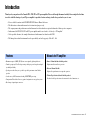 3
3
-
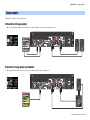 4
4
-
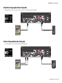 5
5
-
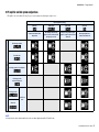 6
6
-
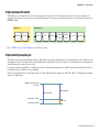 7
7
-
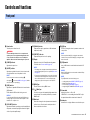 8
8
-
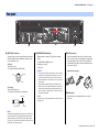 9
9
-
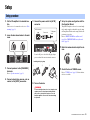 10
10
-
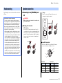 11
11
-
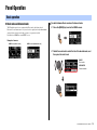 12
12
-
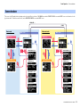 13
13
-
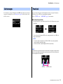 14
14
-
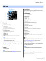 15
15
-
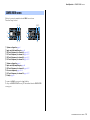 16
16
-
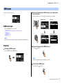 17
17
-
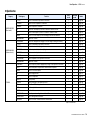 18
18
-
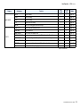 19
19
-
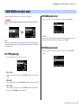 20
20
-
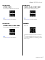 21
21
-
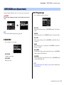 22
22
-
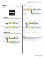 23
23
-
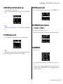 24
24
-
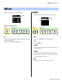 25
25
-
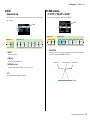 26
26
-
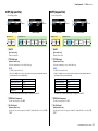 27
27
-
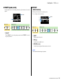 28
28
-
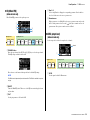 29
29
-
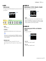 30
30
-
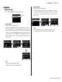 31
31
-
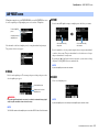 32
32
-
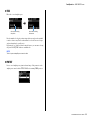 33
33
-
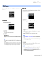 34
34
-
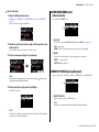 35
35
-
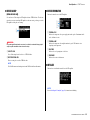 36
36
-
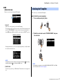 37
37
-
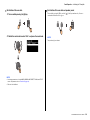 38
38
-
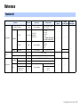 39
39
-
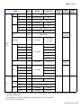 40
40
-
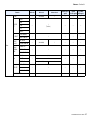 41
41
-
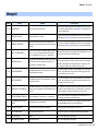 42
42
-
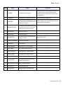 43
43
-
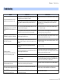 44
44
-
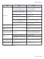 45
45
-
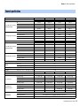 46
46
-
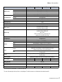 47
47
-
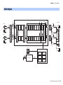 48
48
-
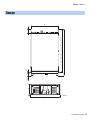 49
49
-
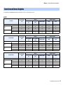 50
50
-
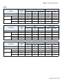 51
51
-
 52
52
-
 53
53
-
 54
54
-
 55
55
-
 56
56


en otros idiomas
- français: Yamaha V1 Manuel utilisateur
- italiano: Yamaha V1 Manuale utente
- English: Yamaha V1 User manual
- Deutsch: Yamaha V1 Benutzerhandbuch
- русский: Yamaha V1 Руководство пользователя
- Nederlands: Yamaha V1 Handleiding
- português: Yamaha V1 Manual do usuário
- dansk: Yamaha V1 Brugermanual
- polski: Yamaha V1 Instrukcja obsługi
- čeština: Yamaha V1 Uživatelský manuál
- svenska: Yamaha V1 Användarmanual
- Türkçe: Yamaha V1 Kullanım kılavuzu
- suomi: Yamaha V1 Ohjekirja
- română: Yamaha V1 Manual de utilizare