
iNSTALLATiON AND SERVICE MUST BE PERFORMED BY A QUALiFiED iNSTALLER.
iMPORTANT: SAVE FOR LOCAL ELECTRICAL iNSPECTOR'S USE.
READ AND SAVE THESE INSTRUCTIONS FOR FUTURE REFERENCE.
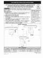
if the information in this manual is not followed e×acfly,
a fire or e×plosion may result causing property damage, personal
injury or death.
FOR YOUR SAFETY:
DO NOT store or use gasoline or other flammable vapors and
liquids in the vicinity of this or any other appliance.
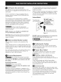
WHAT TO DO iF YOU SMELL GAS:
• DO NOT try to light any appEance.
• DO NOT touch any electrical switch; DO NOT use any phone in
your building.
" Immediately call your gas suppffer from a neighbor's phone.
Follow the gas supplier's instructions.
if you cannot reach your gas supplier, call the fire department.
O
Installation and service must be performed by a qualified
installer, service agency or the gas supplier.
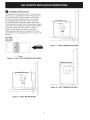
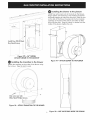
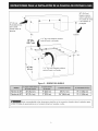
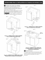
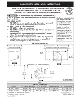
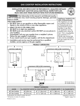
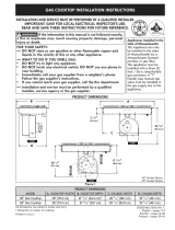
PRODUCT DiMENSiONS
A
o o
o
o N
]
C
Appliances Installed in the
state of Massachusetts:
This Appliance can only
be installed in the state
of Massachusetts by a
Massachusetts licensed
plumber or gas fitter.
This appliance must be
installed with a three (3)
foot / 36 in. long flexible
gas connector. A "T"
handle type manual gas
valve must be installed in
the gas supply line to this
appliance.
20 78" 23 /8"
(51.1 cm) (59.4 cm)
B
o o
D_
Figure 1
30" Gas Cooktop 30" (76.2 cm) 21 mhd' (54.4 cm) 26 m/l?' (68.1 cm)
36" Gas Cooktop 36" (91.4 cm) 21 23/32"(55.1 cm) 32 11/17'(83.0 cm)
All dimensionsare stated in inchesand (cm).
Printed in U.S.A.
18 1s/I?'(48.1 cm)
18 1s/I?'(48.1 cm)
316902490 (1112) Rev.
English - pages 1-14

Important Notes to the Installer
1. Read all instructions contained in these
installation instructions before installing the
cooktop.
2. Remove all packing material before connecting
the electrical supply to the cooktop.
3. Observe all governing codes and ordinances.
4. Be sure to leave these instructions with the
.
consumer.
Note- For operation at 2000 ft. elevations
above see level, appliance rating shall be
reduced by 4 percent for each additional
1000 ft.
Important Note to the Consumer
Keep these instructions with your Use and Care
Guide for future reference.
IMPORTANT SAFETY
INSTRUCTIONS
Installation of this cooktop must conform
with local codes or, in the absence of local
codes, with the National Fuel Gas Code ANSI
Z223.1/NFPA 54 in the United States, or in
Canada, with the Canadian Fuel Gas Code,
CAN/CGA B149 and CAN/CGA B149.2.
• When installed in a manufactured (mobile)
home installation must conform with
the Manufactured Home Construction
and Safety Standard, title 24 CFR, part
3280 [Formerly the Federal Standard for
Mobile Home Construction and Safety,
title 24, HUD (part 280)] or, when such
standard is not applicable, the Standard
for Manufactured Home Installation, ANSI/
NCSBCS A225.1 or with local codes where
applicable.
This cooktop has been design certified by
Underwriters Laboratories (UL). As with any
appliance using gas and generating heat,
there are certain safety precautions you
should follow. You will find them in the Use
and Care Guide, read it carefully.
• Be sure your cooktop is installed and
grounded properly by a qualified installer
or service technician.
This cooktop must be electrically grounded
in accordance with local codes or, in their
absence, with the National Electrical Code
ANSi/NFPA No. 70--latest edition in
the United States, or in Canada, with the
Canadian Electrical Code, CSA C22.1 Part
1.
• The burners can be lit manually during an
electrical power outage. To light a burner,
hold a lit match to the burner head, then
slowly turn the Surface Control knob to
LITE. Use caution when lighting burners
manually.
DO NOT store items of interest
to children in cabinets above the cooktop.
Children could be seriously burned climbing
on the cooktop to reach items.
• To eliminate the need to reach over the
surface burners, cabinet storage space
above the burners should be avoided.
• Adjust surface burner flame size so it does
not extend beyond the edge of the cooking
utensil. Excessive flame is hazardous.
Never use your cooktop for
warming or heating the room. Prolonged use
of the cooktop without adequate ventilation
can be hazardous.
Storage on Appliance.
Flammable materials should not be stored
near surface units. This includes paper,
plastic and cloth items, such as cookbooks,
plasticware and towels, as well as flammable
liquids. DO NOT store explosives, such as
aerosol cans, on or near the appliance.
Flammable materials may explode and result
in fire or property damage.
The electrical power to the
cooktop must be shut off while gas line
connections are being made. Failure to do so
could result in serious injury or death.

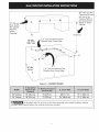
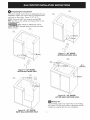
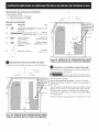
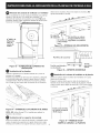
13" (33 cm)
Max. Depth
For Cabinet
Installed
Above
Cooktop.
18" Min.
(45.7 cm)
1 3/8" (3.5 cm) Minimum Flat
Distance from Cutout Edge.
30" (76.2 cm) Min.
Clearance Between
the Top of the
Cooking Platform
and Unprotected
Clearance
\
24" Min.
(61cm)
1 3/8" (3.5 cm) Minimum Flat
Distance from Cutout Edge.
Figure 2 - CABINET DESIGN
30" Cooktop 30" (76.2 cm) 9" (22.9 cm) 28" (71.1cm) 19 1/8"(48.6 cm)
36" Cooktop 36" (91.4 cm) 9" (22.9 cm) 34" (86.4 cm) 19 1/8"(48.6 crn)
[ _[__ To eliminate the risk of burns or fire from reaching over heated surfaces, cabinet
storage space located above the cooktop should be avoided.

Required Tools for Installation
- Phillips Screwdriver
- 1/4" Nut driver / Ratchet
- 7/16 I' Nut driver / Ratchet
Supplied Hardware
Description
(4)
(2)
(4)
(6)
1/4-20 Nylon Insert
7/16" Hex Nut
Blower (fig. 20)
#10-24 3.5" Brackets
Long Phillips Screw (fig. 15 & 16)
(_ #8-18 Wide Head Transition Duct
Phillips Screw (fig. 18)
#8-18 Black Plenum and Wire
%" Hex Head Screw Box (fig. 17 & 21)
Countertop
(2) Hold Down Bracket (fig. 15 & 16)
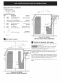
3
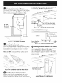
(8.3 cm)
q_
1 1II
(27.9cm)
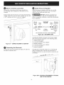
Wall Outlet Location
Install the electric wall outlet within the shaded area.
cL
I _1 11 1/2"
'_- 3/4,-, (29.2cm)
6" 8
(15.2cm) (22.2cm)
Figure 3B - 30" MODEL
ELECTRICALOUTLET INSTALL DIMENSIONS
Provide an Adequate Gas Supply
This cooktop is designed to operate on natural gas at 4"
of manifold pressure only.
A pressure regulator must be connected
in series with the manifold on the cooktop and must
remain in series with the supply line.
For proper operation, the maximum inlet pressure to the
regulator must be no more than 14" of water column
(W.C.) pressure.
For checking the regulator, the inlet pressure must be at
least 1" (or 2.5 kPa) greater than the regulator manifold
pressure setting. The regulator is set for 4" of manifold
pressure, the inlet pressure must be at least 5".
The gas supply line to the range should be 1/2" or 3/4"
pipe.
Figure 3A - 36" MODEL
ELECTRICALOUTLET INSTALL DIMENSIONS

LP/Propane Gas Conversion
This appliance can be used with Natural gas or LP/
Propane gas. It is shipped from the factory for use with
natural gas.
A kit for converting to LP gas is supplied with your
cooktop. The kit is marked "FOR LP/PROPANE GAS
CONVERSION".
The conversion must be performed by a qualified
service technician in accordance with the kit instructions
and all local codes and requirements. Failure to follow
instructions could result in serious injury or property
damage. The qualified agency performing this work
assumes responsibility for the conversion.
Failure to make the appropriate
conversion can result in serious personal injury and
property damage.
NOTE: Purchase a new flexible line. DO NOT USE
AN OLD PREVIOUSLY USED LINE.
Important: Remove all packing material and literature
from cooktop before connecting gas and electrical
supply to cooktop.
Model and Serial Number Location
The serial plate is located on the underside of the
cooktop.
When ordering parts for or making inquires about your
cooktop, always be sure to include the model and serial
numbers and a lot number or letter from the serial plate
of your cooktop.
Your serial plate also tells you the rating of the burners,
the type of fuel and the pressure the cooktop was
adjusted for when it left the factory.
Electrical Requirements
]20 volt, 60 Hertz, properly grounded
branch circuit protected by a 15 amp circuit breaker or
time delay fuse. DO NOT use an extension cord with
this cooktop.
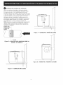
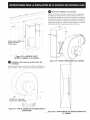
Grounding instructions
IMPORTANT Please read carefully.
For personal safety, fhls appliance must
be properly grounded.
The power cord of this appliance is equipped with a
3-prong (grounding) plug which mates with a standard
3-prong grounding wall receptacle (see Figure 4) to
minimize the possibility of electric shock hazard from
the appliance.
The wall receptacle and circuit should be checked by
a qualified electrician to make sure the receptacle is
properly grounded.
Where a standard 2-prong wall receptacle is installed,
it is the personal responsibility and obligation of the
consumer to have it replaced by a properly grounded
3-prong wall receptacle.
Preferred Method
Grounding type
wall receptacle
NOT, under -_
any circumstances, I
cut, remove, |
or bypass the |
grounding prong.J
Power supply cord with
3-prong grounding plug.
Figure 4
DO NOT, under any circumstances, cut or remove the
third (ground) prong from the power cord.
_ Disconnect electrical supply cord from
wall receptacle before servicing cooktop.
Positioning the Cooktop
The exhaust vent from the cooktop must be located
between wall studs or floor joists so that the ductwork
may be installed properly
Prepare Base Cabinet
This cooktop is designed to fit easily into a variety
of cabinets. However, some cabinets may require
modifications.
Preparing a Cabinet with Drawers
If the cabinet has drawers, the drawers must be
removed and the drawer fronts attached to the front of
the cabinet.
Verify internal length and width of base cabinet
In some cabinets, the sides or back wall may need to
be cut out, and the corner braces removed in order to
accommodate the unit.
Counterfop Cutout
Countertops with a rolled front edge and radius at the
base of the backsplash may not provide the fiat surface
area required to accommodate the cooktop.
Cut countertop opening according to the dimensions
shown in Figure 2. The opening must be cut squarely
with sides parallel to each other, front and rear
perpendicular to the sides.
5

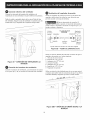
Installing the Ductwork
Use galvanized or aluminum duct in 6" round or 3½"
x 10" size, or a combination of both. PVC duct should
be used if installing under a poured concrete slab.
Use the shortest and straightest duct run possible.
For satisfactory performance, the duct run should
not exceed 100 feet equivalent length. Refer to the
"Calculating Duct Length" chart for equivalent lengths.
(see page 14). All duct joints should be fastened with a
screw and sealed with tape as shown in Figure 5.
NOTE: Local building code must be followed in
specifying approved type and schedule of ALL duct
used. Always use an appropriate roof or wall cap with
damper.
Duct Tape
Over Seam
and Screw
!
Figure 7 - DUCT THROUGH-THE-FLOOR
Screw
Figure 5 - DUCT TAPE OVER SEAM AND SCREW
° '. ° I["'
Figure 6 - DUCT ON-THE-FLOOR
Figure 8 - DUCT THROUGH-THE-WALL

Preparing for Ductwork
Cut hole in cabinet wall or floor as appropriate for your
installation. Make sure exhaust duct is located between
wall studs or floor joists. Figure 9, 10, 11 & 12.
NOTE: Ductwork MUST be vented to outside. DO
NOT vent into a wall, ceiling, crawlspace, attic or any
concealed space.
When cutting or drilling into wall or
ceiling, DO NOT damage electrical wiring and other
hidden utilities. CUTOUT
CENTER
i
i
//
CUTOUT
CENTER ....
I
I
I
Figure 11 - 36" MODEL
BOTTOM DUCTWORK HOLE
CUTOUT
CENTER- -I
8 1/16"
CUTOUT
Figure 9 - 30" MODEL
BOTTOM DUCTWORK HOLE
CUTOUT
CENTER
(ll.0cm) :
/
/
(20.3crn)
Figure 10 - 30" MODEL
BACK WALL DUCTWORK HOLE
.6cm)
Figure 12 - 36" MODEL
LEFTOR RIGHT DUCTWORK HOLE
_'_ Makeup Air
Local building codes may require the use of makeup
air systems. Consult local codes to determine specific
makeup air requirements for your installation.
7

Blower to Ductwork Alignment
The use of flexible ducting is discouraged because it
can severely restrict airflow. If the blower outlet and the
floor or wall duct location DO NOT align, then Nexible
METAL ducting can be used to adapt to an offset.
I-- q
o o
6" MAX.
Center line
To Center
line Offset
Figure 13 - DUCTWORK ALIGNMENT
Insfallincj the Cooktop
Lift the cooktop by the side edges as shown.
Lower the cooktop into the countertop opening, guiding
it into position. Support the underside and lower slowly.
Carefully remove your Nngers one corner at a time to
lower the cooktop into position.
NOTE: DO NO]" use Silicone RTV or caulk to seal the
cooktop to the countertop.
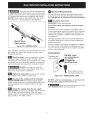
the backside of the countertop. To prevent damage to
the countertop, DO NOT overtighten the screw.
One Long
Philllps Screw
Figure |5 - ATTACH THE TWO BRACKETS
_T_ #8-18 Black Hex Head
Screws Attached to Cooktop
Cooktop
Screws Supplled _ 6 ps
with Cooktop screw
Figure |6 - iNSTALLATiON BRACKETS
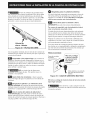
Installincj the blower plenum to the cooktop
V_/ith the blower opening on the right slide the plenum
into the opening in the bottom of the cooktop.
Push up on the plenum until the mounting rails on the
sides of the plenum contact the bottom of the cooktop.
Install four #8-18 x 3/8" sheet metal screws to hold the
Figure 14 - LOWERING COOKTOP INTO CUTOUT
Installing the installation brackets
Remove screws from the cooktop chassis and use to
attach the hold down bracket to the bottom of the
chassis. Insert the screw into the bracket until it contacts
Install Four #8-18 Blacl_
Hex Head icrews
Figure 17- 30" MODEL
ATTACH PLENUM TO THE COOl{TOP

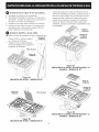
Installing the blower to the plenum
Install four nylon insert nuts to the studs on the blower,
finger tighten until resistance is felt. Position the blower
discharge opening to match the ductwork. Slide the nuts
on the side of the blower housing into the four keyhole
openings on the side of the plenum and allow to slide
down into the slots. Using a wrench or ratchet from the
inside of the plenum tighten the nuts.
Figure 17B - 36" MODEL
ATTACH PLENUM TO THE COOKTOP
Installing the transition to the blower
Attach the transition to the outlet of the blower using
four screws. Tape the joint to seal.
Figure 19 - ATTACH BLOWERTO THE PLENUM
One screw per side
Wide Head Phillips Screws
Figure 18 - ATTACH TRANSMON TO THE BLOWER
9 Figure 20 - NUT LOCATIONS iNSiDE THE PLENUM

Blower electrical connection
Connect the 5-pin plug on the blower assembly to
the matching 5-pin receptacle on the bottom of the
cooktop.
Fold all wires into the wire box on the end of the blower
conduit. Fasten the wire box to the cooktop with two #8
x 3/8" making sure that no wires are trapped.
Install Pressure Regulator
Install the pressure regulator with the arrow on the
regulator pointing up toward the unit in a position
where you can reach the access cap.
_DO NOT make the connection too
tight. The regulator is die cast. Overtightening may
crack the regulator resulting in a gas leak and possible
fire or explosion.
Figure 21 - CONNECT BLOWERTO COOKTOP
Connecting the Ductwork
Connect the ductwork prepared in Steps 8, 9 and 10 to
the blower transition duct.
Manual GAS FLOW Pressure
Shutoff Flare I_ Flare Regulator
Valve Union Union
0n_!;_ t t Nip1'le_p
__. Nipple Flexible
Access
Off Connector
Cap
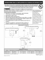
All connections must be wrench-tightened
Figure 22 - GAS SUPPLYLINE
Assemble the flexible connector from the gas supply
pipe to the pressure regulator in the following order:
1. manual shutoff valve
2. 1/2" (1.3 cm) nipple
3. 1/2" (1.3 cm) flare union adapter
4. flexible connector
5. 1/2" (1.3 cm) flare union adapter
6. 1/2" (1.3 cm) nipple
7. pressure regulator
Use pipe-joint compound made for use with Natural
and LP/Propane gas to seal all gas connections. If
flexible connectors are used, be certain connectors are
not kinked.
............ _j
Figure 22B - PHYSICAL ATTACHMENT OF THE GAS
LINE TO THE COOKTOP
10

_The supply line must be equipped with
an approved manual shutoff valve. This valve should be
located in the same room as the cooktop and should be
in a location that allows ease of opening and closing.
DO NOT block access to the shutoff valve. The valve is
for turning on or shutting off gas to the appliance.
Shutoff Valve -
Open position
Figure 23 - SHUTOFF VALVE
Once regulator is in place, open the shutoff valve in the
gas supply line. Wait a few minutes for gas to move
through the gas line.
_ Check for leaks. After connecting the cooktop
to the gas supply, check the system for leaks with a
manometer. If a manometer is not available, turn on the
gas supply and use a liquid leak detector (or soap and
water) at all joints and connections to check for leaks.
Flr_]__ DO NOT use a flame to check for
leaks from gas connections. Checking for leaks with a
flame may result in a fire or explosion.
Tighten a[[ connections if necessary to prevent
gas leakage in the cooktop or supply line.
Disconnect this cooktop and its individual
manual shutoff valve from the gas supply piping
system during any pressure testing of that system at test
pressures greater than 1/2 psig (3.5 kPa or 14"water
column).
| Isolate the cooktop from the gas suppJy
piping system by dosing its individual manual shutoff
valve during any pressure testing of the gas supply
piping system at test pressures equal to or less than 1/2
psig (3.5 kPa or 14" water column).
Electrical Requirements
120 volt, 60 Hertz, properly grounded branch circuit
protected by a 15 amp circuit breaker or time delay
fuse. DO NOT use an extension cord with this cooktop.
| Grounding Instructions
iMPORTANT Please read carefully.
For personal safety, this appliance must be properly
grounded.
The power cord of this appliance is equipped with a
3-prong (grounding) plug which mates with a standard
3-prong grounding wall receptacle (see Figure 25) to
minimize the possibility of electric shock hazard from
the appliance.
The wall receptacle and circuit should be checked by
a qualified electrician to make sure the receptacle is
properly grounded.
Where a standard 2-prong wail receptacle is installed,
it is the personal responsibility and obligation of the
consumer to have it replaced by a properly grounded
3-prong wall receptacle.
Preferred Method
Grounding type
wail receptacle
NOT, under
any circumstances,
cut, remove,
or bypass the
grounding prong.
Power supply cord with
3-prong grounding plug.
Figure 24 - POWER SUPPLYCORD
DO NOT, under any circumstances, cut or remove the
thlrd (ground) prong from the power cord.
_ Disconnect electrical supply cord from
wail receptacle before servicing cooktop.
11

Install Burner Caps
A. Unpack the burner grates.
B. Burners: Unpack the Burner heads and burner caps.
Place the burner heads and caps on the matching
bases.
C. The caps should be level after installation
D. Be sure that all the burner caps burner head are
correctly placed BEFORE using your cooktop
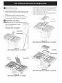
Install Filter and Grates
DO NOT operate the vent without the filter in place.
* Place the filter diagonally through Vent Chamber
...............................................I ............................................
the vent chamber. ...._..... '
* Make sure it rests, at an angle, on ]
the supports in the vent opening. "'i
f
Chamber
Figure 25
VENT FILTER LOCATION - 30" MODEL
* Carefully place vent grate seal over the vent chamber
on the cooktop, with the side marked FRONT to the
front. Make sure the collar on the bottom of the seal
is fully inserted the vent opening.
* Place the vent grate over the vent opening. Place the
burner grates over the burners.
Figure 27
VENT GRATE AND SEAL LOCATION - 30" MODEL
Grate
Vent Grate Seal
Vent
Chamber .......
Figure 28
VENT GRATEAND SEAL LOCATION - 36" MODEL
Figure 26
VENT FILTERLOCATION - 36" MODEL
12

Check Operation
Refer to the Use and Care Guide packaged with the
cooktop for operating instructions and for care and
cleaning of your cooktop.
Turn on Electrical Power and Open Main Shutoff
Gas Valve
_ Check the igniters
Operation of electric igniters should be checked after
cooktop and supply line connectors have been carefully
checked for leaks and the cooktop has been connected
to electric power.
To operate the surface burner:
A. Push in and turn a surface burner knob to the LITE
position. You will hear a small ticking noise; this
is the sound of the electric ignitor which lights the
burner.
B. After the burner lights, turn to the desired flame
size. The controls DO NOT have to be set at a
particular mark. Use the marks as a guide and
adjust the flame as needed.
When All Hookups are Complete
Make sure all controls are left in the OFF position.
Make sure the flow of combustion and ventilation air to
the cooktop is unobstructed.
Before You Call for Service
Read the Before You Call for Service Checklist and
operating instructions in your Use and Care Guide.
It may save you time and expense. The list includes
common occurrences that are not the result of defective
workmanship or materials in this appliance.
Refer to the warranty in your Use and Care Guide for
our service phone number and address. Please call or
write if you have inquiries about your product and/or
need to order parts.
13

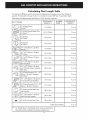
Calculating Duct Length Table
For maximum efficiency, use the shortest and straightest duct possible. Use as few fittings as
possible. For best performance, the duct run should not exceed 100 feet of equivalent length.
Calculations are approximate and based on HVAC industry standards.
DUCT PIECES EQUIVALENT NUMBER EQUIVALENT
LENGTH X USED -- LENGTH
6" (15.2cm) Round
Straight _ 1 Ft. (0.3m) Ft. or m
6" (15.2cm) Round Metal Flex
No Bends _ 1.5 Ft. (0.45m) Ft. or m
(_ 6" (15.2cm) 10 Ft. (3m) Ft.
or m
90 ° Elbow
Q_ 6" (15.2cm)
45 ° Elbow 5 Ft. (1.5m) Ft. or m
[__ 31/4" x 10" (8.2cm x 25.4cm)
Straight _ 1 Ft. (0.3m) Ft. or m
31/4" x 10" (8.2cm x 25.4cm) 10 Ft. (3m) Ft. or m
90 ° Elbow
31/4'' x 10" (8.2cm x 25.4cm)
45 ° Elbow 5 Ft. (1.5m) Ft. or m
31/4" x 10"
10 Ft. (3m) Ft. or m
(8.2cm X 25.4cm)
90 ° Flat Elbow
31/46:,X 10" (8.2cm x 25.4cm)
to (15.2cm) Round Transition 30 Ft. (9m) Ft. or m
90 ° Elbow
6" (15.2cm) Round to 31/4" x 10"
(8.2cm x 25.4cm) Transition 30 Ft. (9m) Ft. or m
90 ° Elbow
31/4" x 10" (8.2cm x 25.4cm) to 5 Ft. (1.5m) Ft. or m
6" (15.2cm) Round Transition
6" (15.2cm) Round to 31,/4 '' X 10"
(8.2cm x 25.4cm) Transition 5 Ft. (1.5m) Ft. or m
6" (15.2cm) Round Wall Cap
with Damper 30 Ft. (9m) Ft. or m
[_ 31/4" x 10" (8.2cm x 25.4cm)
Wall Cap with Damper 30 Ft. (9m) Ft. or m
(15.2cm) Round Roof Cap 30 Ft. (9m) Ft. or m
6"
TOTAL DUCTWORK Ft. or m
_ For Straight Round / Rectangular Duct, measure actual linear
feet used and then multiply by Equivalent Length shown.
14

TODA TAREADEINSTALACiON O IV_NTENIMIENTO DEBERAREALIZARLAUN INSTALADORCUALIFICADO.
IMPORTANTE: GUARDE ESTASINSTRUCCIONES PARA ELiNSPECTOR LOCAL DE ELECTRICIDAD.
LEA Y GUARDE ESTAS INSTRUCCIONES PARA FUTURAS CONSULTAS.
Si no slgue las instrucciones recogldas en este manual al pie
de la leira se podrfa produclr un incendlo o una explosi6n que causarfa da_os
materiales, lesiones corporales o incluso la muerte.
POR RAZONES DE SEGURIDAD:
m NO guarde ni use gasollna u otros liquidos o gases inflamables
cerca de este o de cualquier otto electrodom_sflco.
QUE HACER SI HUELE A GAS:
• NO encienda ningOn electrodom_sfico.
• NO toque ningOninterruptor el_ctrlco, NO ufiEce ningOnfel_fono en el edificio.
• Llame a su compa_fa de gas de inmediafo desde el tel_fono de algOn veclno.
Siga las instrucciones que le d_ la compa_fa.
• Si no conslgue ponerse en conlacto con la compafiia de gas, llame a los
bomberos.
Toda tarea de instalaci6n o manfenimiento deber6 realizarla un
instalador cualificado, el servicio t_cnico o la compafiia de gas.
Para electrodom_sficos en el
estado de Massachusetts:
En el estado de
Massachusetts, este
electrodom_stico debe
instalarlo un instalador de gas
o un fontanero con licencia
de Massachusetts. Se debe
instalar un conector de gas
flexible que no supere los 3
pies/36 pulgadas. Se debe
instalar una v61vula manual
con mango en Ten la tuberfa
de gas utilizada para este
electrodom_stico.
DIMENSIONES DEL PRODUCTO
A l=
o N
o o
o
C
i
20 %"
(51.1 cm)
233/8"
(59.4 cm)
o o
D_
Figura 1
Modelo de 30" 30" (76,2 cm) 2113132"(54,4 cm) 26 13/16"(68,1 cm)
Modelo de 36" 36" (91,4 crn) 21 23/32"(55,1 crn) 32 11/16"(83,0 crn)
Todas las dimensiones se expresan en pulgadas y (cm).
Impreso en EE. UU.
18 15116"(48,1 cm)
18 15116"(48,1 cm)
316902490 (1112) Rev.
Espa_ol - p6ginas 1-14

Informaci6n importante para el instalador
1. Lea todas las instrucciones de instalaci6n
suministradas antes de preceder a instalar la
plancha.
2. Retire todo el embalaje antes de conectar el
suministro ei_ctrico aJ electrodom_stico.
3. Tenga en cuenta Ja normativa y los c6digos locales.
4. Aseg6rese de dejar estas instrucciones aJ propietario.
5. Nora: Para el use a m6s de 2000 pies de altura
sobre el niveJ del mar, la potencia del aparato
deber6 reducirse un 4 per ciento per cada 1000 pies
adicionales.
Informaci6n importante para el propietario
Conserve estas instrucciones con su Gufa de use y
cuidado para futuras consultas.
INSTRUCCIONES IMPORTANTES
PARA LA SEGURIDAD
La instalaci6n de esta plancha de cocinar debe
realizarse en conformidad con los c6digos locales
o, si estos no existen, con el National Fuel Gas
Code ANSi Z223.1/NFPA 54 en Estados Unidos, o
con el Canadian Fuel Gas Code, CAN/CGA B149 y
CAN/CGA B149.2 en Canad6.
• La instalaci6n de las unidades dise_ados para
casas (m6viles) deben respetar los "Manufactured
Home Construction and Safety Standards, titulo
24 CFR, arficulo 3280 (antes el The Federal
Standard for Mobile Home Construction and
Safety, tituto 24, HUD, artfculo 280)" o, cuando
la normativa no sea aplicable, con el Standard
for Manufactured Home Installation, ANSI/
NCSBCS A225.1 o con los c6digos locales.
Esta plancha ha side dise_ada y certificada
per Underwriters Laboratories (UL). Come con
cualquier electrodom6stico que funcione con gas
y genere calor, hay una serie de precauciones de
seguridad que debe seguir al utilizar esta plancha
de cocinar. Las encontrar6 en la Gufa de use y
cuidado_ lea estas instrucciones detenidamente.
• AsegOrese de que un instalador cualificado o el
personal del servlcJo t_cnico instalan V conectan
a fierra correctamente este electrodom_sfico.
La plancha de cocinar debe conectarse a
fierra de acuerdo con los c6dlgos locales o, de
no exisfir, con la 61tima edici6n del National
Electrical Code ANSI/NFPA No. 70 en Estados
Unidos o con el Canadian Electrical Code, CSA
C22.1 Part 1 en Canad6.
• En case de corte del suministro el_ctrlco puede
encender los quemadores manualmente. Para
encender un quemador, coloque una cerilla
encendida cerca de la cabeza del quemador V
gire el mando de control lentamente basra la
posJcJ6n LITE. Tenga cuidado al encender los
quemadores manualmente.
NO almacene objetos que puedan
captar la atenci6n de los ni_os en los muebles
situados sobre el electrodom_sfico. Los ni_os
podrfan intentar subirse al electrodom6stico y esto
podrfa provocar lesiones graves.
• Seria recomendable evitar almacenar utensilios
en los muebles situados sobre la plancha para
evltar el tenet que acceder a ellos.
• Ajuste la llama de forma que no sobresalga
fuera del borde del utensilio. Una llama de un
tamale excesivo es peligrosa.
Nunca ufillce este electrodom_sfice
para calentar la habitaci6n. El use prolongado de
la plancha sin la ventilaci6n adecuada podria ser
peligroso.
AImacenamiento cerca del
electrodom_sfico. No guarde materiales
inflamables cerca de este electrodom_sfico. Esto
incluye objetos de papel, pl6stico o tela, come libros
de cocina, utensilios de pl6stico o pa_os, asf come
Ifquidos inflamables. NO almacene materiales
explosives, per ejemplo, aerosoles, cerca del
electrodom@stico. Los materiales inflamables podrfan
explotar y provocar un incendio o da_os materiales.
Corte el suminlstro el_ctrlco de la
plancha mientras que se instalan las conexiones
de la tuberia de gas. Si no Io hace podrian
provocarse lesJones graves e incluso la muerte.

13" (33 cm)
Profundidad m6x.
del mueble
situado sobre la
plancha.
13/8" (3,5 cm) Distancia minima
entre el hueco y el bordeo
30" (76,2 cm)
Espacio minimo
entre la plancha y
el mueble de metal
__1 o de madera no
egida
Es_acio
Plancha de 30"
Plancha de 36"
13/8" (3,5 cm) Distancia minima
entre el hueco y el borde.
Figura 2 - DISEI_IO DEL MUEBLE
iiii_!i_!i!_!_!_i!i_i_i_!ii_i!_!ii!_!_!!_:i_!ii_i_!ii!ii!_i!_!ii_!i_!i__i!iii!ii!!i!ii!!
ii!ii!ii!i_ii!ii!ii_ii_ii_ii_ii_ii_ii_ii!ililili_!_iiiiiiii!ii_!i_!_ii_!ii!i!ii!!i_!_!_i_iii:_!i_ii!ii_il¸ii'il¸ii!i!ii!ii!i!iiiiiiii_i:ii_i_i_i_!
30" (76,2 cm)
36" (91,4 cm)
!!!!!i!ii!ii!ii!iiiiiii!ii!ii!!i!i!i!iii!iiiiiiiiiiii_iiiii!_!_!i_i_i_i!i_i_i_i_!_i_i_!_!_!i_i_i_!i_!_!i_i_iiiiii_i_!_iii_iiiiiiiiiiiiiiiiii!!ii:¸
ii_!_!i_!_!!_!i!_!i!_!_!!iii_i_ii!ii!i!i!ii!_i_ii_i_i_ii_i_i_ii_i_i_i_i_ii_ii_i_i_ii_i_i_i!_!_!_!i!_!_i_i!_!_!_!i_i_i!_!_!_i_!i_!_!_!i_!i_!i_!i_!_!_!_!i_!i_!_i!i!i_ii_iiiiiiiiiiiiiiiiiiiiiiiiiiiiiiiiiiiiiiiiiiiiiiiiiiiiiiiiiiiiiiii_ii_ii
9" (22,9 cm)
9" (22,9 cm)
i¸i¸_!_!_!_!_!_!_!_i!i!i_!i_!i_i_!i!_!_i_!!i!!i!_!!!i_!_!_!_i_!_!!i_i_!iiiiiii_i!_i!_!_!_i!ii!ii!iiiiiiiiiiiiiiiiiiiiiiiiiiiiiiiiiiiiiiiiiiiiiiiiiii!i!i!i!_
28" (71,1 cm)
34" (86,4 cm)
iiiiiiiiiiii,!i_!iiiiiiiiiiiiiiiiiiiiii_i_iii_ii_ii_ii_ii_i_i!i_ii_ii_ii_iiiiiiii_i!i!_!i!ii_!_!i!i!i_i_ii_ii_ii_iiiiiiii!!!_ii_ii_ii_ii_i_i_i_i_i_i_i_i_ii_ii_ii_ii_i_!_!i_!i_!i_!i_!i_i_iiiiiii_i_i_i!i!i!i_i_ii_i!i_i!i_i!i_ii_ii_ii_ii_ii_ii_ii_ii_ii_ii_iiiiiiii_ii_ii_iiiiiiii_iii_ii_i_i_!i_!i_!i_!i_iiiii_ii_ii_ii_iiiiiiii_iiiii!!!_iiiii_iiiiiiii_i_i_i_i_i_i_i_i_iiiiiiiiiiiiiiiiiiiiii_i_!_!
19 1/8" (48,6 cm)
19 1/8" (48,6 cm)
Seda recomendable evitar almacenar utensilios en los armarios situados sobre la plancha para
evitar el riesgo de quemaduras por el contacto directo al acceder a ellos.

Herramientas necesarias para la instalaci6n
- Destornillador Phillips
- ½" Liave para tuercas / trinquete
- z/16"Llave para tuercas / trinquete
Elementos suminlstrados
_antidad Descripci6n Uso
1/4-20 tuercas de cabeza Ventilador (fig. 20)
(4) hexagonal con insertos de
nil6n 7/16"
Soportes
(2) #10-24 3.5" Torniilo con
cabeza Phillips largo (fig. 15 y 16)
(4) (_ #8-18 Torniios con Conducto de
cabeza Phillips transici6n (fig. 18)
#8-18 Negros 1/4" C_mara y caja de
(6)
Tornillos con cabeza cableado (fig. 17 y 21)
hexagonal
Encimera
(2) Soporte de sujecci6n (fig. 15 y 16)
3
(8.3 cm)
cL
1 1II
(27.9 cm)
Ublcaci6n de la toma de corriente de pared
Instaie la toma de corriente de pared en e[ Orea sombreada.
q_
I _1 11 1/2"
I= 3/4-, (29.2 cm)
6" 8
(15.2 cm) (22.2 cm)
Ubicaci6n reco-
mendada para eli
tubo de[ suminis- [
tro de gas ]
Figura 3B - MODELO DE30" DIMENSIONES DEL HUECO
PARA LA INSTALACION DE LA TOMA DE CORRIENTE
Conexi6n a un suminlstro de gas adecuado
Esta plancha se ha diseffado para funcionar Onicamente con
un colector de gas natural de 4".
_EI colector debe estar conectado en serie
a un regulador de presi6n y debe conectarse en serie con la
Ifnea de suministro de gas.
Para un funcionamien|a adecuado, [a presi6n de entrada
mOxima al regulador no debe ser superior a una coiumna de
agua de 14".
Para comprobar e[ regu[ador, [a presi6n de entrada a[ mismo
deberO ser de a[ menos 1" (o 2,5 kPa) mayor que [a presi6n
de[ co[ector de[ regu[ador. E[ regu[ador se configura para
una presi6n de co[ector de 4", [a presi6n de entrada deberO
ser a[ menos de 5".
La [inea de suministro de gas debe ser una tuberia de 1/2" o 3/4".
Figura 3A - MODELO DE 36" DIMENSIONES DEL HUECO
PARA LA INSTALACION DE LA TOMA DE CORRIENTE

Conversi6n a gas propano/LP
Este eJectrodom_stico ha sido dise_ado para utiNzar gas
natural o gas propano. Los valores predeterminados de
f6brica se han establecido para su uso con gas natural.
Con este producto se suministra un kit para Ja conversi6n a
gas propano. El kit se titula "PARA CONVERSION A GAS
PROPANO/LP".
La conversi6n a gas propano debe realizarla el personal
cualificado deJ servicio t6cnico de acuerdo con Jas
instrucciones suministradas y con todos los c6digos y
normativas locales. De Jo contrario, podrian producirse graves
lesiones o daBos materiales. La agencia cualiflcada que
ejecute esta conversi6n se responsabilizar6 de este trabajo.
_Si la conversi6n no se realizara
correctamente podrian provocarse lesiones corporales y
daBos materiales.
NOTA: Adquiera una Irnea nueva y flexible. NO UTILICE
UNA L{NEA USADA ANTERIORMENTE.
Jmportante: Retire todo el embalaje y Jas instrucciones de Ja
plancha antes de conectar el suministro de gas y el el6ctrico
al electrodom_stico.
Ubicaci6n del n6mero de serie ¥ modelo
La placa de serie est6 ubicada en la parte inferior de
la plancha.
Si tiene alguna pregunta sobre el electrodom@stico o
si desea encargar alguna pieza, aseg6rese de incluir el
modelo, el n0mero de serie y el n0mero o la letra dei
Iote que encontrar6 en la pJaca de serie de Ja plancha.
La placa de serie tambi@n induye informaci6n
sobre la potencia de los quemadores, el tipo de
combustible y el ajuste de presi6n fijado en la f6brica.
Requisltos para el sumlnlstro el_ctrico
_Un circuito derivado conectado
correctamente a tierra de 120 voJtios, 60 hercios protegido
por un disyuntor de 15 amperios o un fusible de retardo.
NO utilice un alargador el_ctrico para conectar este
electrodom_stico.
Instrucciones para la conexi6n a fierra
JMPORTANTE Lea estas instrucciones detenidamente.
_Por razones de seguridad, este
eJectrodom_.stico deber6 estar correctamente conectado a tierra.
El cable el6ctrico de este eJectrodom_stico est6 equipado
con un enchufe con tres clavijas (con toma de tierra) que
encaja con una toma de corriente para tres clavijas (consulte
Figura 4) para reducir el riesgo de descargas el6ctricas.
P6ngase en contacto con un electricista cualificado para
comprobar el circuito y que Ja toma de corriente de pared
est6 correctamente conectada a tierra.
Si la 6nica toma de corriente de pared al alcance es para
dos clavijas, es su responsabilidad y obligaci6n reemplazarla
por otra toma de corriente de pared para tres clavijas que
est_ correctamente conectada a tierra.
M_todo recomendado
Toma de corriente
de pared
con conexi6n
a tierra
NO corte, extralga_
o desv_e la clavija|
de toma de tJerra |
bajo nincj6n |
concepto. /
Cable eJ6ctrico con enchufe
con toma de tierra de tres
clavijas
Figura 4
NO corte o extraiga la cJavija de toma de tierra del enchufe
bajo nJngOn concepto.
_ Antes de Ilevar a cabo cualquier tarea de
mantenimiento, desconecte el cable de suministro el6ctrico de
Ja toma de corriente de pared.
Fijaci6n de la plancha
El extractor de Ja plancha debe estar situado entre un
soporte en Ja pared o en una viga de soporte de manera que
permita instalar eJ conducto de ventiJaci6n correctamente.
Preparaci6n del mueble inferior
Este eJectrodom6stico ha sido dise_ado para encajar en
diferentes muebles. Puede que algunos muebles necesiten
modificaciones.
Instalaci6n en un mueble con cajones
Si el mueble tiene cajones, deber6 retirarlos y acoplar la
zona deJantera de los cajones al mueble.
Compruebe la Jongitud y Ja anchura deJ mueble.
En algunos muebles puede que sea necesario cortar los
laterales o la pared de Ja zona trasera y retirar las escuadras
para poder instalar la unidad.
Corte de la encJmera
Las encimeras con el borde curvo y una curva en la base
de los azulejos no proporcionarian una superficie plana
necesaria para instalar Ja plancha.
Realice un corte en la encimera de acuerdo con Jas
dimensiones que se muestran en la Figura 2. El hueco debe
formar un cuadrado cuyos lados sean paraJelos y Ja parte
delantera y la trasera sean perpendicuJares a los lados.
5

Instalaci6n del conducto de ventilaci6n
Utilice un conducto galvanizado o de alumino redondo
de o 6" o 3'q/4x 10", o una combinaci6n de ambos. Utilice
un conducto de PVC siva a instalarlo ba]o una Iosa de
hormig6n. Intente que el conducto recorra el tramo mrs corto
y mrs recto posible. Para un rendimiento 6primo, el conducto
no deberia exceder los cien pies de Iongitud. Consulte la
tabla para calcular la Iongitud del conducto para ver la
equivalencia de medidas. (consulte la p_gina 14). Las juntas
del conducto deben a]ustarse con un tornillo y sellarse con
cinta adhesiva tal y como se muestra en la Figura 5.
NOTA: Debe tener en cuenta la normativa local de construcci6n
respecto al tipo y la planificaci6n de TODOS los conductos
utilizados. Utilice siempre una tapa de techo o de pared con
regulador de ventilaci6n.
Colocar clnta
adhesiva sobre
la uni6n y el
tornillo
Tornillo
Figura 5 - COLOCAR CINTA ADHESIVA SOBRE LA
UNION Y ELTORNILLO
° '. ° II"'
II 2
Figura 6- CONDUCTO EN EL SUELO
Figura 7 - CONDUCTO A TRAVES DEL SUELO
Figura 8 - CONDUCTO A TRAVES DE LA PARED

Instalaci6n del conducto de ventilaci6n
Haga un orificio en la pared del mueble o en el suelo,
dependiendo de Io que sea mrs adecuado para su
instalaci6n en particular. Aseg0rese de que el conducto del
extractor est_ situado entre un soporte en la pared o una
viga de soporte. Figura 9, 10, 11 y 12.
NOTA: Ei conducto de ventilaci6n DEBE desembocar en el exterior.
NO instale el conducto de forma que desemboque en un muro,
techos, 6ticos, s6tanos de servicio o cualquier otro espacio oculto.
AI cortar o taladrar en una pared o en el
techo, NO dafie el cableado el6ctrico ni otras instalaciones.
CENTRO DEL
HUECO
CENTRO DEL
HU ECO / _ I
CENTRO DEL
HUECO
CENTRO DEL
HUECO
cm)
Figura 11 - MODELO DE 36" ORIFICIO INFERIOR
PARA EL CONDUCTO DEVENTILACION
CENTRO DEL
HUECO
CENTRO DEL
HUECO
8 1/16"
Figura 9 - MODELO DE 30" ORIFICIO INFERIOR
PARA EL CONDUCTO DEVENTILACION
CENTRO DEL
HUECO
CENTROHuECODEL 5/16!1 (11,0cm)
Figura 10 - MODELO DE 30" ORIFICIO EN LA PARED
TRASERA PARA ELCONDUCTO DEVENTILACION
7
cm)
Figura 12- MODELO DE 36" ORIFICIO EN
ELLATERALDERECHO O IZQUIERDO PARA EL
CONDUCTO DE VENTILACION
_ Tratarnlento de alre
De acuerdo con la normativa local de construcci6n, podria
ser necesario instalar un sistema de tratamiento de aire.
Consulte la normativa local para obtener mrs informaci6n
sobre los requisitos de tratamiento de aire para su
instralaci6n.

Alineaci6n del condudo de ventilaci6n ¥ el ventilador
No se recomienda el uso de conductos flexibles pues podrian
impedir el fujo de aire. Si la salida del ventilador y la
ubicaci6n del conducto en la pared o en el suelo NO est6n
aNneadas, podria utilizar conductos flexibles de METAL para
favorecer la nivelaci6n.
6" MAX. de
dlferencia
entre el
centro de
arnbos
inferior de la encimera. Para evitar da_ar la encimera, NO
apriete demasiado el tornillo.
de suiecci6n \ _Das tarnillas con cabeza
ae sujecclon \ hexagonal #8-18 negros,
Un tarnilla con atornilladas a la plancha
cabeza Phillips LI
largo
Figura 15 - ATORNILLE LOS DOS SOPORTES
Parrilla de cocinar
Figura 13 - ALINEACI6N DELCONDUCTO DE
VENTILACI6N
Instalaci6n de la plancha
Levante la plancha por los bordes laterales tal y como se
muestra en la imagen.
Introduzca la plancha en el hueco de la encimera, col6quela
en la posici6n adecuada. Apoye la parte inferior y b6jela
cuidadosamente. Retire las manos de las esquinas, primero
una y luego la otra, hasta dejar la plancha en su ubicaci6n.
6 Tornillo
TarniHas sumlnistradas :on cabeza
con la plancha PhiHips
Figura 16 - SOPORTES DE MONTAJE
Instalaci6n de la c6mara del ventHador en la plancha
Deslice la c6mara hacia el orificio del ventilador en la zona
inferior de la plancha.
Empuje la c6mara hasta que los railes de montaje de los
laterales de la misma toquen el fondo de la plancha. Instale
cuatro tornillos para chapa de metal (#8 x 3/8") para sujetar
Figura 14 - INTRODUZCA LA PLANCHA EN EL HUECO
NOTA: NO utilice silicona RTV ni masilla para adherir la
plancha a la encimera.
Instalaci6n de los soportes de montaje
Retire los tornillos de la caja de la plancha y col6quelos para
sujetar el soporte de sujecci6n a la parte inferior de la caja.
Introduzca el tornillo en el soporte hasta que toque la parte
Instale cuatro torniHos
con cabeza hexagonal
#8-18 negros.
/
Figura 17-MODELO DE 30"
SUJETELA CAMARA A LA PLANCHA

Instale cuatro tornillos con
cabeza he×agonal
#8-18 negros,
I
I
I
Uni6n del venfilador a la c_mara
Instaie cuatro tuercas con insertos de nii6n en los soportes dei
ventiiador, aiOsteJos Jo m_ximo posible. CoJoque eJ orificio de
descarga deJ ventiiador de forma que coincida con ei conducto
de ventiJaci6n. Deslice las tuercas en el laterai dei ventiiador de
manera que encaien en Jos orificios en eJ lateral de ia c_mara y
desJiceias en Jas ranuras. UtiJice una Have ingJesa o un trinquete
desde el interior de ia c_mara para aiustar ias tuercas.
Ficjura 17B- MODELO DE 36"
SUJETELA CAMARA A LA PLANCHA
Instalaci6n del conducto de transici6n del
venfilador
Sujete el conducto de transici6n a la salida del ventilador con
cuatro tornillos. Utilice cinta adhesiva para quede sellado.
Ficjura 19 - UNA ELVENTILADOR A LA CAMARA
Un tomillo en cada lado
Tomillos con cabeza Phillips
Ficjura 18 - UNA ELCONDUCTO DE TRANSICION AL
VENTILADOR
9 Ficjura 20 - UBICACION DE LASTUERCAS DENTRO DE
LA CAMARA

Conexi6nel_ctricadelvenfilador
Conecte los cinco polos del conjunto del ventilador en el
recept6culo con cinco entradas en la parte inferior de la plancha.
Doble los cables y gu6rdelos dentro de la caja al final del tubo
del ventilador. Asegure la caja de cableado a la plancha con dos
tornillos #8 x 3/8", aseg6rese de no aprisionar ning6n cable.
Figura 21 - CONEXI6N DEL VENTILADOR A LA
PLANCHA
Conexi6n del conducto de venfilaci6n
Conecte el conducto de ventilaci6n, cuya instalaci6n se explico
en los pasos 8, 9 y 10, al conducto de transici6n del ventilador.
Instalaci6n del regulador de presi6n
Instale el regulador de presi6n de forma que la flecha del
regulador se_ale hacia la unidad en una ubicaci6n que
permita acceder a la tapa de entrada.
_NO ajuste demasiado conexi6n.
la El
regulador est6 fundido a presi6n. AI ajustarla demasiado se
_uede romper el regulador causando una fuga de gas y un
)osible incendio o explosi6n.
V61vula FLU, JO DE GAS Regulador
de cierre _ de presi6n
Cerrada
Conector
flexible Tapa de
entrada
Ajuste todas las uniones con una Ilave inglesa
Figure 22 - TUBERiADELSUMINISTRO DEGAS
Monte el conector flexible del tubo del suministro de gas al
regulador de presi6n en el orden siguiente:
1. V61vula de cierre manual
2. Boquilla de 1/2" (1,3 cm)
3. Adaptator de 1/2" (1,3 cm)
4. Conector flexible
5. Adaptator de 1/2" (1,3 cm)
6. Boquilla de 1/2" (1,3 cm)
7. Regulador de presi6n
Utilice una junta de tubo dise_ada para el uso con gas natural
y propano para sellar todas las conexiones de gas. Si se utiNzan
conectores flexibles, aseg6rese que estos no est_n torcidos.
............ _j
Figura 22B- UNION DE LA TUBERJA DE GAS A LA
PLANCHA
10

_EI tubo de suministro de gas debe induir
una v_lvula de cierre manual certificada. Esta v61vula debe
estar ubicada en la misma habitaci6n que la plancha de
coninar en un lugar que faciNte la apertura y el cierre. NO
bloque6 el acceso a la v61vula de cierre. La v_lvula sirve
para abrir o cerrar el paso de gas al electrodom_stico.
V_ivula de
cierre - Abierta
Figura 23 - VALVULA DE CIERRE
Con el regulador instalado, abra la v_lvula de la tuberia de
suministro de gas° Espere unos minutos para que el gas fluya
a trav6s de la tuberia.
_Cornpruebe si hay alguna fuga. Tras conectar la
plancha al suministro de gas, compruebe el sistema con un
man6metro. Si no cuenta con un man6metro, d6 la vuelta al
suministro de gas de la cocina y utilice un detector de fugas
I[quidas (o agua y ]ab6n) en todas las uniones y conexiones
para verificar si existen fugas.
_NO use ningOn tipo de llama para
comprobar si hay fugas de gas. Esto podria causar un
incendio o una explosi6n.
_ Ajuste todas las conexlones si fuera necesario
para evitar fugas de gas en la pJancha o en la tuberia del
suministro.
Desconecte la plancha y su v61vula de clerre
manual individual del suministro de gas durante durante
cualquier ensayo de presi6n del sistema en ensayos de presi6n
superiores a 1/2 psig (3,5 kPa o columna de agua de 14").
m
Aisle la cocina del slsterna de tuberia del
surnlnlstro de gas, para ello, cierre la v_lvula de cierre
manual individual durante cualquier ensayo de presi6n del
sistema de suministro de gas en ensayos iguales o inferiores a
1/2 psig (3,5 kPa o de coiumna de agua de 14").
Requisltos para el surninistro ei_ctrico
Un circuito derivado conectado correctamente a tierra de
120 voltios, 60 hercios protegido por un disyuntor de 15
amperios o un fusible de retardo. NO utiHce un alargador
el_.ctrlco para conectar este electrodom_sticoo
_ Instrucclanes para la conexi6n a tlerra
IMPORTANTE Lea estas instrucciones detenidamente.
Par razones de seguridad, este electrodom_.stico deber6
estar correctarnente conectado a tierra.
El cable el6ctrico de este electrodom_stico est6 equipado
con un enchufe con tres davijas (con toma de tierra) que
encaia con una toma de corriente para tres daviias (consulte
Figura 25) para reducir el riesgo de descargas el6ctricas.
P6ngase en contacto con un electricista cualificado para
comprobar el circuito y que la toma de corriente de pared
est_ correctamente conectada a tierra.
Si la Onica toma de corriente de pared al alcance es para
dos claviias, es su responsabilidad y obNgaci6n reemplazarla
por otra toma de corriente de pared para tres claviias que
est_ correctamente conectada a tierrao
M_todo recornendado
Toma de corriente NO cotter extralga
de pared o desvie la clavija
con conexi6n a de torna de tlerra
tierra ba]o ningOn
conceF
Cable el6ctrico con enchufe
con toma de tierra de tres
claviias
Figura 24 - CABLE DE SUMINISTRO ELECTRICO
NO carte o extraiga la clavlja de torna de tlerra del enchufe
bajo nlngOn conceptoo
_ Antes de Ilevar a cabo cualquier tarea de
mantenimiento, desconecte el cable de suministro el6ctrico de
la toma de corriente.
11

Instalaci6n de las tapas de los quemadores,
A. Desembale las parrillas de los quemadores.
B. Quemadores: Desembale las cabezas y las tapas de los
quemadores. Coloque las cabezas de los quemadores y
las tapas en las bases correspondientes.
C. Verifique que las tapas est6n niveladas tras instalarlas.
D. Aseggrese de que todas las tapas y las cabezas de los
quemadores est6n correctamente situadas ANTES de
poner la plancha en funcionamiento.
Instalaci6n del filtro y de las rejillas
NO utilice el sistema de ventilaci6n sin haber colocado el filtro.
C6mara de
Coloque el filtro en posici6n diagonal
en la c6mara de ventilaci6n.
Aseggrese de que se queda apoyado,
en posici6n diagonal, en los soportes en
la apertura de ventilaci6n.
\ Fiffro de grasa\
C6mara de
ventilaci6n
ventilaci6n
I
f
/
/
/
• Coloque la bandeja de la rejilla de ventilaci6n sobre la
c6mara de ventilaci6n en la plancha, asegOrese de que el
lado con la marca FRONT est_ colocado hacia el frente.
Aseggrese de que el collarin de la parte inferior de la
bande]a se ha insertado en la apertura de ventilaci6n.
• Coloque la rejilla de ventilaci6n sobre la apertura de
ventilaci6n. Coloque las parrillas de los quemadores sobre
los quemadores.
Rejilla de
ventitaci6n
Bandeja de
la rejilla de
ventllaci6n
Figura 27
UBICACI6N DE LA REJILLA DE VENTJLACI6N Y LA
BANDEJA - MODELO DE 30"
C6mara de
ventffaci6n
......'\\\\\
_Ffftro de grasa
Figura 26
UBICACI6N DEL FILTRO - MODELO DE 36"
12
Figura 28
UBICACI6N DE LA REJILLA DE VENTILACI6N Y LA
BANDEJA - MODELO DE 36"

Compruebe el funcionamiento
Consulte la Guia de uso y cuidado suministrada con este
electrodom_stico si desea obtener m6s informaci6n sobre
las instrucciones generales de funcionamiento, asi como
sugerencias de cuidado y limpieza.
_ Conecte el suminlstro el_.ctrlco y abra la v61vula de
clerre principal del gas
_ Compruebe los encendedores
Compruebe el funcionamiento de los encendedores tras
haber revisado detenidamente la plancha de cocinar y
los conectores del tubo del suministro para comprobar si
hay fugas y tras haber conectado el electrodom_stico al
suministro el6ctrico.
Para poner en funcionamiento los quemadores:
A. Presione y gire el mando de control hasta la posici6n
LITE. Escuchar6 un clic. El encendedor el6ctrico emite
este sonido al encender el quemador.
B. Cuando se haya encendido el quemador, gire el mando
de control hasta conseguir el tamaSo de llama deseado.
Los mandos NO tienen que estar en una posici6n en
particular. Utilice Jas marcas como guia y ajuste el
tamaSo de la llama seg6n Io necesite.
Cuando se havan reallzado todas las conexiones
Aseg6rese de que todos los mandos de control est6n en la
posici6n OFF.
Aseggrese de que el flujo de combusti6n y de ventilaci6n de
aire de la plancha no est6n obstruidos.
Antes de solicitar serviclo t_cnico
Lea la tabla de la secci6n antes de solicitar servicio t_cnico
y Jas instrucciones generales de funcionamiento en la Guia
de uso y culdado. Puede ahorrarle tiempo y dinero. Esta Jista
incluye situaciones comunes que no son el resultado de mano
de obra o materiales defectuosos en este electrodom6stico.
Consulte Ja garantia incluida en la Guia de uso y cuidado,
en ella encontrar6 el nOmero de tel6fono y direcci6n de
nuestro servicio t_cnico. No dude en Ilamar por tel6fono o en
escribirnos si tiene alguna duda sobre el electrodom_stico o
si necesita encargar alguna pieza.
13

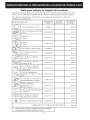
Tabla para calcular ia Iongitud del conducto
Para me]orar la eficiencia, intente que el conducto sea Io m6s corto y el recorrido Io m6s recto posible. Use el menor
nOmero de uniones posible. Para un rendimiento 6ptimo, el conducto no deberia exceder los cien pies de Iongitud.
Estos c61culos son aproximados y est6n basados en los est6ndares de la industria de la calefacci6n,
ventilaci6n y aire acondicionado.
PARTES DEL CONDUCTO EquivalenciaDE UNIDADES EQUIVALENCIA
ALTURA X UTILIZADAS : DE ALTURA
6" (15,2 cm) Redondos rectos 1 pie (0,3 m) pies o m
1,5 pies (0,45 m) pies o m
6"
(15.2 crn)
Redondo recto de metal
flexible _
(_ 6" (15,2 cm) 10 (3 m)
pies pies
o m
90 ° Codo
(_ 6" (15,2 cm)
45 ° Codo 5 pies (1,5 m) pies o m
[__ x (8,2 cm x 25,4 cm) Recto 1 pie (0,3 m) pies o m
3V4" 10"
3V4" x 10" (8,2 cm x 25,4 cm)
10
pies (3 m) pies
o rn
Codo de 90 °
3V4" x 10" (8,2 cmx 25,4 cm)Codo de 45 ° 5 pies (1,5 m) pies o m
3V4" x 10" (8,2 cmx 25,4 cm)
10
pies (3 m) pies
o rn
Codo piano de 90 °
3V4" x 10" (8,2 cmx 25,4 cm) a
6" (15,2 cm) Codos redondos de 30 pies (9 m) pies o m
transici6n de 90 °
6" (15,2 crn) Codo redondo de
transici6n 3V4" x 10" (8,2 cm x 25,4 cm) 30 pies (9 m) pies o m
de 90 °
31/4" x 10" (8,2 cm x 25,4 cm) a 6"
(15,2 cm) Redondos de transici6n 5 pies (1,5 m) pies o m
6" (15,2 cm) Redondo
de transici6n 3V4" x 10" 5 pies (1,5 m) pies o m
(8,2 cm x 25,4 cm)
(_ 6" (15,2 cm) Tapa redonda de pared
con regulador 30 pies (9 m) pies o m
[_ 3V4" x 10" (8,2 cm x 25,4 cm)
Tapa de pared con regulador 30 pies (9 m) pies o m
6" (15,2 cm) Tapa redonda de techo 30 pies (9 m) pies o m
MEDIDA TOTAL DEL CONDUCTO DE VENTILACKDN pies o m
_ Para el conducto redondo o rectangular, mida los pies utilizados y
multiplfquelos por Io Iogitud equivolente mostrodo.
14
-
 1
1
-
 2
2
-
 3
3
-
 4
4
-
 5
5
-
 6
6
-
 7
7
-
 8
8
-
 9
9
-
 10
10
-
 11
11
-
 12
12
-
 13
13
-
 14
14
-
 15
15
-
 16
16
-
 17
17
-
 18
18
-
 19
19
-
 20
20
-
 21
21
-
 22
22
-
 23
23
-
 24
24
-
 25
25
-
 26
26
-
 27
27
-
 28
28


UL 79031123110 Guía de instalación
- Tipo
- Guía de instalación
- Este manual también es adecuado para
en otros idiomas
- English: UL 79031123110 Installation guide
Otros documentos
-
 Kenmore Elite 31123 Guía de instalación
-
 Kenmore Elite 79031113211 Guía de instalación
-
 Kenmore Elite 79031123510 Guía de instalación
-
Kenmore Elite 79044113511 Guía de instalación
-
GE PGP990DEN1BB El manual del propietario
-
GE Profile PGP989SNSS Manual de usuario
-
-
GE Profile JGP989BCBB El manual del propietario
-


