Kenmore Elite 79031113211 Guía de instalación
- Tipo
- Guía de instalación

INSTALLATION AND SERVICE MUST BE PERFORMED BY A QUALIFIED iNSTALLER.
iMPORTANT: SAVE FOR LOCAL ELECTRICAL iNSPECTOR'S USE.
READ AND SAVE THESE iNSTRUCTiONS FOR FUTURE REFERENCE.
if the information in this manual is not followed e×acfly,
a fire or e×plosion may result causing property damage, personal
injury or death.
FOR YOUR SAFETY:
DO NOT store or use gasoline or other flammable vapors and
liquids in the vicinity of this or any other appliance.
WHAT TO DO iF YOU SMELL GAS:
* DO NOT tw to light any appliance.
* DO NOT touch any electrical switch; DO NOT use any phone in
your building.
* Immediately call your gas supplier from a neighbor's phone.
Foffow the gas suppiier's instructions.
* if you cannot reach your gas supplier, cail the fire department.
installation and service must be performed by a qualified
installer, service agency or the gas supplier.
Appliances Installed in the
state of Massachusetts:
This Appliance can only
be installed in the state
of Massachusetts by a
Massachusetts licensed
plumber or gas fitter.
This appliance must be
installed with a three (3)
foot / 36 in. long flexible
gas connector. A "T"
handle type manual gas
valve must be installed in
the gas supply line to this
appliance.
B D
i
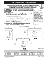
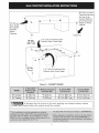
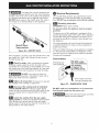
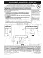
PRODUCT DIMENSIONS
A
o o
D
V
20 1/8"
(51.1 cm)
1
3 11/16 n
(9.4 cm)
C
17 13/16"
(45.2 cm)
l
Figure |
21 _3/3_"(54.4 ¢rn)_ 26 _3/_6"(68.1 ¢m)
21 23/3_"(55.1 ¢m) 32 _/_6"(83.0 ¢m)
23 3/8"
(59.4 cm)
36" Model Shown.
30" Model Similar.
30" Gas Cooktop 30" (76.2 cm)
36" Gas Cooktop 36" (91.4 cm)
All dimensions are stated in inches and (cm).
Dimension at center of cooktop.
Printed in U.S.A.
18 15/16"(48.1 cm)
18 15/16"(48.1 cm)
316902922 (1206) Rev. B
English - pages 1-14

important Notes to the installer
1. Read all instructions contained in these
installation instructions before installing the
cooktop.
2. Remove all packing material before connecting
the electrical supply to the cooktop.
3. Observe all governing codes and ordinances.
4. Be sure to leave these instructions with the
.
consumer.
Note: For operation at 2000 ft. elevations
above see level, appliance rating shall be
reduced by 4 percent for each additional
1000 ft.
important Note to the Consumer
Keep these instructions with your Use and Care
Guide for future reference.
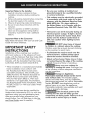
iMPORTANT SAFETY
iNSTRUCTiONS
Installation of this cooktop must conform
with local codes or, in the absence of local
codes, with the National Fuel Gas Code ANSI
Z223.1/NFPA 54 in the United States, or in
Canada, with the Canadian Fuel Gas Code,
CAN/CGA B149 and CAN/CGA B149.2.
• When installed in a manufactured (mobile)
home installation must conform with
the Manufactured Home Construction
and Safety Standard, title 24 CFR, part
3280 [Formerly the Federal Standard for
Mobile Home Construction and Safety,
title 24, HUD (part 280)] or, when such
standard is not applicable, the Standard
for Manufactured Home Installation, ANSI/
NCSBCS A225.1 or with local codes where
applicable.
This cooktop has been design certified by
Underwriters Laboratories (UL). As with any
appliance using gas and generating heat,
there are certain safety precautions you
should follow. You will find them in the Use
and Care Guide., read it carefully.
• Be sure your cooktop is installed and
grounded properly by a qualified installer
or service technician.
This cooktop must be electrically grounded
in accordance with local codes or, in their
absence, with the National Electrical Code
ANSI/NFPA No. 70--latest edition in
the United States, or in Canada, with the
Canadian Electrical Code, CSA C22.1 Part
1.
• The burners can be lit manually during an
electrical power outage. To light a burner,
hold a lit match to the burner head, then
slowly turn the Surface Control knob to
LITE. Use caution when lighting burners
manually.
DO NOT store items of interest
to children in cabinets above the cooktop.
Children could be seriously burned climbing
on the cooktop to reach items.
• To eliminate the need to reach over the
surface burners, cabinet storage space
above the burners should be avoided.
* Adjust surface burner flame size so it does
not extend beyond the edge of the cooking
utensil. Excessive flame is hazardous.
Never use your cooktop for
warming or heating the room. Prolonged use
of the cooktop without adequate ventilation
can be hazardous.
Storage on Appliance.
Flammable materials should not be stored
near surface units. This includes paper,
plastic and cloth items, such as cookbooks,
plasficware and towels, as well as flammable
liquids. DO NOT store explosives, such as
aerosol cans, on or near the appliance.
Flammable materials may explode and result
in flre or property damage.
The electrical power to the
cooktop must be shut off while gas line
connections are being made. Failure to do so
could result in serious injury or death.

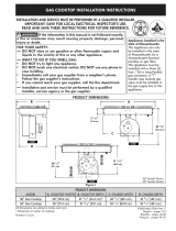
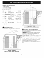
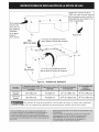
13" (33 cm)
Max. Depth
For Cabinet
installed
Above
Cooktop.
1 3/8" (3.5 cm) Minimum Flat
Distance from Cutout Edge.
30" (76.2 cm) Min.
Clearance Between
the Top of the
Cooking Platform
and Unprotected
__detr Metal
Clearance
i
24" Min.
(61cm)
1 3/8" (3.5 cm) Minimum Fiat
Distance from Cutout Edge.
Figure :2- CABINET DESIGN
30" Cooktop _ 30" (76.2 cm) 9" (22.9 cm)
36" Cooktop 36" (91.4 cm) 9" (22.9 cm)
19 3/16" (49.2 cm)
19 3/16" (49.2 cm)
[ _[__ To eliminate the risk of burns or fire from reaching over heated surfaces, cabinet
storage space located above the cooktop should be avoided.
3

Required Tools for Installation
- Phillips Screwdriver
- 1/4" Nut driver / Ratchet
- 7/16" Nut driver / Ratchet
Supplied Hardware
Qty. Description
(4)
(2)
(4)
(6)
Used for
_) 1/4-20 Nylon Insert
7/16" Hex Nut
Blower (fig. 20)
#10-24 3.5" Brackets
Long Phillips Screw (fig. 15 & 16)
#8-18 Wide Head Transition Duct
Phillips Screw (fig. 18)
#8-18 Black Plenum and Wire
1/4" Hex Head Screw Box (fig. 17 & 21)
Countertop
(2) Hold Down Bracket (fig. 15 & 16)
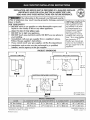
3
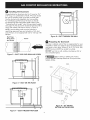
(8.3 cm)
cL
1 1II
(27.9 cm)
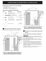
Wall Outlet Location
Install the electric wall outlet within the shaded area.
cL
I _I 11 1/2"
I_ 3/4-, (29.2 cm)
6" 8
(15.2 cm) (22.2 cm)
Recommended I
Gas Supply [
Stub Area ]
r_
Figure 3B - 30" MODEL
ELECTRICALOUTLET INSTALL DIMENSIONS
Provide an Adequate Gas Supply
This cooktop is designed to operate on natural gas at 4"
of manifold pressure only.
A pressure regulator must be connected
in series with the manifold on the cooktop and must
remain in series with the supply line.
For proper operation, the maximum inlet pressure to the
regulator must be no more than 14" of water column
(W.C.) pressure.
For checking the regulatob the inlet pressure must be at
least 1" (or 2.5 kPa) greater than the regulator manifold
pressure setting. The regulator is set for 4" of manifold
pressure, the inlet pressure must be at least 5".
The gas supply line to the range should be 1/2" or 3/4"
pipe.
Figure 3A - 36" MODEL
ELECTRICALOUTLET INSTALL DIMENSIONS

LP/Propane Gas Conversion
This appliance can be used with Natural gas or LP/
Propane gas. It is shipped from the factory for use with
natural gas.
A kit for converting to LP gas is supplied with your
cooktop. The kit is marked "FOR LP/PROPANE GAS
CONVERSION".
The conversion must be performed by a qualified
service technician in accordance with the kit instructions
and all local codes and requirements. Failure to follow
instructions could result in serious injury or property
damage. The qualified agency performing this work
assumes responsibility for the conversion.
Failure to make the appropriate
conversion can result in serious personal injury and
property damage.
NOTE: Purchase a new flexible line. DO NOT USE
AN OLD PREVIOUSLY USED LINE.
Important: Remove all packing material and literature
from cooktop before connecting gas and electrical
supply to cooktop.
Model and Serial Number Location
The serial plate is located on the underside of the
cooktop.
When ordering parts for or making inquires about your
cooktop, always be sure to include the model and serial
numbers and a lot number or letter from the serial plate
of your cooktop.
Your serial plate also tells you the rating of the burners,
the type of fuel and the pressure the cooktop was
adjusted for when it left the factory.
Electrical Requirements
120 volt, 60 Hertz, properly grounded
branch circuit protected by a 15 amp circuit breaker or
time delay fuse. DO NOT use an extension cord wlfh
fhls cooklop.
Grounding Instructions
IMPORTANT Please read carefully.
For personal safety, thls appliance must
be properly grounded.
The power cord of this appliance is equipped with a
3-prong (grounding) plug which mates with a standard
3-prong grounding wall receptacle (see Figure 4) to
minimize the possibility of electric shock hazard from
the appliance.
The wall receptacle and circuit should be checked by
a qualified electrician to make sure the receptacle is
properly grounded.
Where a standard 2-prong wall receptacle is installed,
it is the personal responsibility and obligation of the
consumer to have it replaced by a properly grounded
3-prong wall receptacle.
Preferred Method
Grounding type
wall receptacle
NOT, under -_
any circumstances, I
cut, remove, |
or bypass the |
grounding prong.J
Power supply cord with
3-prong grounding plug.
Figure 4
DO NOT, under any circumstances, cut or remove the
third (ground) prong from the power cord.
_ Disconnect electrical supply cord from
wall receptacle before servicing cooktop.
Positioning the Cooktop
The exhaust vent from the cooktop must be located
between wall studs or floor joists so that the ductwork
may be installed properly
Prepare Base Cabinet
This cooktop is designed to fit easily into a variety
of cabinets. However, some cabinets may require
modifications.
Preparing a Cabinet with Drawers
If the cabinet has drawers, the drawers must be
removed and the drawer fronts attached to the front of
the cabinet.
Verify internal length and width of base cabinet
In some cabinets, the sides or back wail may need to
be cut out, and the corner braces removed in order to
accommodate the unit.
F_ Counfertop Cutout
Countertops with a rolled front edge and radius at the
base of the backsplash may not provide the fiat surface
area required to accommodate the cooktop.
Cut countertop opening according to the dimensions
shown in Figure 2. The opening must be cut squarely
with sides parallel to each other, front and rear
perpendicular to the sides.
5

Installing the Ductwork
Use galvanized or aluminum duct in 6" round or 31/4"
x 10" size, or a combination of both. PVC duct should
be used if installing under a poured concrete slab.
Use the shortest and straightest duct run possible.
For satisfactory performance, the duct run should
not exceed 100 feet equivalent length. Refer to the
"Calculating Duct Length" chart for equivalent lengths.
(see page 14). All duct joints should be fastened with a
screw and sealed with tape as shown in Figure 5.
NOTE: Local building code must be followed in
specifying approved type and schedule of ALL duct
used. Always use an appropriate roof or wail cap with
damper.
Duct Tape
Over Seam
and Screw
j Screw
J
r
I
I
I
I
I
Figure 5 - DUCT TAPE OVER SEAM AND SCREW
Jll o . . o
'l_J'
\/i
%
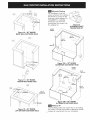
Figure 6 - DUCT ON-THE-FLOOR
Figure 8 - DUCT THROUGH-THE-WALL
Preparing for Ductwork
Cut hole in cabinet wall or floor as appropriate for your
installation. Make sure exhaust duct is located between
wall studs or floor joists. (Figure 9, 10, 11, 12, 13A & 13B)
NOTE: Ductwork MUST be vented to outside.
DO NOT vent into a wail, ceiling, crawispace, attic or
any concealed space.
When cutting or drilling into wail or
ceiling, DO NOT damage electrical wiring and other
hidden utilities.
CUTOUT
CENTER I
Figure 7 - DUCT THROUGH-THE-FLOOR
Figure 9 - 30" MODEL
BOTTOM DUCTWORK HOLE

CUTOUT
CENTER
(ll.Ocm);
/.
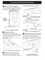
Figure 10 - 30" MODEL
BACK WALL DUCTWORI{ HOLE
CUTOUT
CENTER I
Alternate Ductlng
For installations involving
space restrictions for orienting
the blower to connect to the
ductwork a duct adapter, Kit
5304488297 is available.
Dimensions are shown for
locating the duct cutout with
this adapter kit.
CUTOUT
CENTER
I
I
Figure 13
ALTERNATE DUCT
TRANSITION KiT
(15.2 cm)
i
i
Figure 11 - 36" MODEL
BOTTOM DUCTWORK HOLE
CUTOUT
CENTER- -
I
Figure 12 - 36" MODEL
LEFT OR RIGHT DUCTWORK HOLE
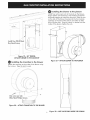
Figure 13A - 30" MODEL
ALTERNATE DUCTWORK HOLE
CUTOUT
/CENTER
8 7/8"
7
....3 s/s"
(9.2 cm)
6 I
(15.2 cm)
Figure 13B - 36" MODEL
22 5/8'1
(57.5 cm)
ALTERNATE DUCTWORI{ HOLE
Makeup Air
Local building codes may require the use of makeup
air systems. Consult local codes to determine specific
makeup air requirements for your installation.

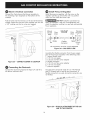
Blower to Dudwork Alignment
The use of flexible ducting is discouraged because it
can severely restrict airflow. If the blower outlet and the
floor or wall duct location DO NOT align, then fexible
METAL ducting can be used to adapt to an offset.
the backside of the countertop. To prevent damage to
the countertop_ DO NOT overfighten the screw.
""T_ #8-18 Black Hex Head
Screws Attached to Cooktop
One Long
Philllps Screw
Figure 16 - ATTACH THE TWO BRACKETS
Cooktop
Figure 14 - DUCTWORK ALIGNMENT
Installing fhe Cookfop
Lift the cooktop by the side edges as shown.
Lower the cooktop into the countertop opening_ guiding
it into position. Support the underside and lower slowly.
Carefully remove your fingers one corner at a time to
lower the cooktop into position.
NOTE: DO NOT use Silicone RTV or caulk to seal the
cool<top to the countertop.
L_
Screws Supplied -_r 6 ps
with Cooktop screw
Figure 17- INSTALLATION BRACKETS
Installing fhe blower plenum fo fhe cooktop
With the blower opening on the right slide the plenum
into the opening in the bottom of the cooktop.
Push up on the plenum until the mounting rails on the
sides of the plenum contact the bottom of the cooktop.
Install four _8 x 3/8" sheet metal screws to hold the
Figure 15 - LOWERING COOKTOP INTO CUTOUT
installing fhe installation brackefs
Remove screws from the cooktop chassis and use to
attach the hold down bracket to the bottom of the
chassis. Insert the screw into the bracket until it contacts
Figure 18- 30" MODEL
ATTACH PLENUM TO THE COOKTOP

.... _s_ -__ ............
I
Installing fhe blower fo fhe plenum
Install four nylon insert nuts to the studs on the blower,
finger tighten until resistance is felt. Position the blower
discharge opening to match the ductwork. Slide the nuts
on the side of the blower housing into the four keyhole
openings on the side of the plenum and allow to slide
down into the slots. Using awrench or ratchet from the
inside of the plenum tighten the nuts.
Figure 19 - 36" MODEL
ATTACH PLENUM TO THE COOKTOP
installing the fransifion to the blower
Attach the transition to the outlet of the blower using
four screws. Tape the joint to seal.
Figure 21 - ATTACH BLOWER TO THE PLENUM
One screw per side
Wide Head Phillips Screws
Figure 20 - ATTACH TRANSITION TO THE BLOWER
9 Figure 22 - NUT LOCATIONS INSIDE THE PLENUM

Blower electrical connection
Connect the 5-pin plug on the blower assembly to
the matching 5-pin receptacle on the bottom of the
cooktop.
Fold all wires into the wire box on the end of the blower
conduit. Fasten the wire box to the cooktop with two #8
x 3/8" making sure that no wires are trapped.
Install Pressure Regulator
Install the pressure regulator with the arrow on the
regulator pointing up toward the unit in a position
where you can reach the access cap.
_DO NOT make the connection too
tight. The regulator is die cast. Overtightening may
crack the regulator resulting in a gas leak and possible
fire or explosion.
Figure 23 - CONNECT BLOWERTO COOKTOP
Connecting the Ductwork
Connect the ductwork prepared in Steps 8, 9 and 10 to
the blower transition duct.
Manual GAS FLOW Pressure
Shutoff Flare _ Flare Regulator
Valve Union Union
Access
Off Connector
Cap
All connections must be wrench-tightened
Figure 24 - GAS SUPPLY LiNE
Assemble the flexible connector from the gas supply
pipe to the pressure regulator in the following order:
1. manual shutoff: valve
2. 1/2" (1.3 cm) nipple
3. 1/2" (1.3 cm) flare union adapter
4. flexible connector
5. 1/2" (1.3 cm) flare union adapter
6. 1/2" (1.3 cm) nipple
7. pressure regulator
Use pipe-joint compound made for use with Natural
and LP/Propane gas to seal all gas connections. If
flexible connectors are used, be certain connectors are
not kinked.
Figure 25 - PHYSICAL ATTACHMENT OF THE GAS
LINE TO THE COOKTOP
lO

_The supply line must be equipped with
an approved manual shutoff valve. This valve should be
located in the same room as the cooktop and should be
in a location that allows ease of opening and closing.
DO NOT block access to the shutoff valve. The valve is
for turning on or shutting off gas to the appliance.
Shutoff Valve =
Open position
Figure 26 - SHUTOFF VALVE
Once regulator is in place, open the shutoff valve in the
gas supply line. Wait a few minutes for gas to move
through the gas line.
_ Check for leaks. After connecting the cool<top
to the gas supply, check the system for leaks with a
manometer. If a manometer is not available, turn on the
gas supply and use a liquid leak detector (or soap and
water) at all joints and connections to check for leaks.
_J__ DO NOT use a flame to check for
leaks from gas connections. Checking for leaks with a
flame may result in a fire or explosion.
| Tighten all connections if necessary to prevent
gas leakage in the cooktop or supply line.
Disconnect this cooktop and its indivldual
manual shutoff valve from the gas supply piping
system during any pressure testing of that system at test
pressures greater than 1/2 psig (3.5 kPa or 14"water
column).
isolate the cooktop from the gas supply
piping system by closing its individual manual shutoff
valve during any pressure testing of the gas supply
piping system at test pressures equal to or Jess than 1/2
psig (3.5 kPa or 14" water column).
Electrical Requirements
120 volt, 60 Hertz, properly grounded branch circuit
protected by a 15 amp circuit breaker or time delay
fuse. DO NOT use an extension cord with this cooktop.
| Grounding instructions
iMPORTANT Please read carefully.
For personal safety, this appilance must be properly
grounded.
The power cord of this appliance is equipped with a
3=prong (grounding) plug which mates with a standard
3=prong grounding wall receptacle (see Figure 27) to
minimize the possibility of electric shock hazard from
the appliance.
The wail receptacle and circuit should be checked by
a qualified electrician to make sure the receptacle is
properly grounded.
Where a standard 2=prong wail receptacle is installed,
it is the personal responsibility and obligation of the
consumer to have it replaced by a properly grounded
3=prong wall receptacle.
Preferred Method
Grounding type
wall receptacle
NOT, under _
any circumstances, I
cut, remove, |
or bypass the |
grounding prong.J
Power supply cord with
3=prong grounding plug.
Figure 27 - POWER SUPPLYCORD
DO NOT, under any circumstances, cut or remove the
third (ground) prong from the power cord.
_ Disconnect electrical supply cord from
wall receptacle before servicing cooktop.
11

install Burner Caps
A. Unpack the burner grates.
B. Burners: Unpack the Burner heads and burner caps.
Place the burner heads and caps on the matching
bases.
C. The caps should be level after installation
D. Be sure that all the burner caps burner head are
correctly placed BEFORE using your cooktop
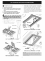
install Filter, Vent Grate Seal and Grates
• Place the filter diagonally through
the vent chamben
• Maize sure it rests, at an angle, on
the supports in the vent opening.
Grease Filler
\ \
Chamber
nf
Figure 28
VENT FILTER LOCATION - 30" M(
Venf Chamber
)DEL
Vent
Chamber .......
Grease Filler
Carefully place vent grate seal over the vent chamber
on the cooktop as shown in Figures 30 - 31. Maize sure
the collar on the bottom of the seal is fully inserted
into the vent opening. Remove the 1/4" hex head
screw located in the vent chamber underneath the tab
on the vent grate seal. Bend the tab on the vent grate
seal down into the vent chamber and secure it with the
hex head screw.
Vent
Grate
Seal
Figure 30
VENT GRATE SEAL ATTACHMENT - 30" MODEL
Ven,'
Grate _
Seal
Hex Screw
Figure 31
VENT GRATE SEAL ATTACHMENT - 36" MODEL
Figure 29
VENT FILTER LOCATION - 36" MODEL
12

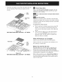
PIocetheventgroteontopoftheventgroteseol_over
theventopening.Piocetheburnergratesoverthe
burners.
Vent
Grate
Vent Grate
Seal
Figure 32
VENT GRATE AND SEAL LOCATION - 30" MODEL
Check Operation
Refer to the Use and Care Guide packaged with the
cooktop for operating instructions and for care and
cleaning of your cooktop.
_Turn on EJectrlca_ Power and Open Main Shutoff
Gas Valve
r_'_'_ Check [he I{::jni|ers
Operation of electric igniters should be checked after
cooktop and supply line connectors have been carefully
checked for leaks ond the cooktop hos been connected
to electric power.
To opera|e the surface burner:
A. Push in and turn o surface burner knob to the LITE
position. You will hear o small ticking noise; this
is the sound of the electric ignitor which lights the
burner.
B. After the burner lights, turn to the desired flame
size. The controls DO NOT have to be set at o
particular mark. Use the marks as o guide and
adjust the flame as needed.
Vent Grate
Vent
Grate
Seal
Figure 33
VENT GRATE AND SEAL LOCATION - 36" MODEL
When All Hookups are Complete
Make sure oil controls ore left in the OFF position.
Make sure the flow of combustion and ventilation air to
the cooktop is unobstructed.
Before You Call for Service
Read the Before You Coil for Service Checklist and
operating instructions in your Use and Care Guide.
It may save you time and expense. The list includes
common occurrences that ore not the result of defective
workmanship or materials in this appliance.
Refer to the warranty in your Use and Care Guide for
our service phone number ond address. Please coil or
write if you have inquiries about your product and/or
need to order parts.
13

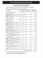
Calculating Duct Length Table
For maximum ef_ciency, use the shortest and straightest duct possible. Use as few fittings as
possible. For best performance_ the duct run should not exceed 100 feet of equivalent length.
Calculations are approximate and based on HVAC industry standards.
DUCT PIECES EQUIVALENT NUMBER EQUIVALENT
LENGTH X USED : LENGTH
(_ 6" (15.2cm) RoundStraight _ 1 Ft. (0.3m) Ft. or m
_) 6" (15.2cm) Round Metal Flex
No Bends _ 1.5 Ft. (0.45m) Ft. or m
(_ 6" (15.2cm)
90 ° Elbow 10 Ft. (3m) Ft. or m
(_ 6" (15.2cm)
45 ° Elbow 5 Ft. (1.5m) Ft. or m
31/4" x 10" (8.2cm x 25.4cm)
Straight _ 1 Ft. (0.3m) Ft. or m
31/4" x 10" (8.2cm x 25.4cm)
90 ° Elbow 10 Ft. (3m) Ft. or m
31/4" x 10" (8.2cm x 25.4cm)
45 ° Elbow 5 Ft. (1.5m) Ft. or m
31/4" x 10" (8.2cm x 25.4cm)
90 ° Flat Elbow 10 Ft. (3m) Ft. or m
31/4" x 10" (8.2cm x 25.4cm)
to 6" (15.2cm) Round Transition 30 Ft. (9m) Ft. or m
90 ° Elbow
6" (15.2cm) Round to 31/4" X 101'
(8.2cm x 25.4cm) Transition 30 Ft. (9m) Ft. or m
90 ° Elbow
31/4'' x 10" (8.2cm x 25.4cm) to 5 Ft. (].5m) Ft. or m
6" (15.2cm) Round Transition
¢:_ 6" (15.2cm) Round to 31/4" x 10"
(8.2cm x 25.4cm) Transition 5 Ft. (].5m) Ft. or m
30 Ft. (9m) Ft. or m
6"
(15.2cm)
Round Wall
Cap
with Damper
[_ 30 Ft. (9m) Ft. or m
31/4" 10"
(8.2cm
25.4cm)X X
WaN Cap with Damper
(15.2cm) Round Roof Cap 30 Ft. (9m) Ft. or m
6"
TOTAL DUCTWORK Ft. or m
_ For Straight Round / Rectangular Duct° measure actual linear
feet used and then multiply by Equivalent Length shown.
14

LAINSTALACIONY ELSERVICIODEBENSERREALIZADOSPORUN INSTALADORCALIFICADO.
IMPORTANTE: CONSERVE ESTASINSTRUCCIONES PARAEL USO POR PARTEDEL iNSPECTOR DE
INSTALACIONES ELF:CTRICASLEAY GUARDE ESTASINSTRUCCIONES PARAREFERENCIA EN ELFUTURO.
_Si no se cumplen estrlctamente las instrucclones y los avlsos informafivos
contenldos en este manual, podrian produclrse incendlos y e×ploslones que causen da_os
a blenes, leslones personales y hasta la muerte°
PARA SU SEGURIDAD:
NO almacene nl ufillce gasollna nl otros liquldos inflamabies (y los vapores de
dlchos materlales) en las cercanias de este nl de nlngOn otto electrodom_stl¢o,
QUE DEBE HACER Si HAY OLOR A GAS:
® NO utlllce nlngOn electrodom_stl¢o,
® NO toque nlng6n interruptor el_ctrlco; NO utlllce nlng6n tel_fono en nlng6n lugar
de la edfficaci6n.
® Comuniquese de inmedlato con su proveedor de gas desde la casa de un veclno°
Siga las instrucclones que le d_ el proveedor de gas°
® Si no puede comunlcarse con su proveedor de gas, flame al departamento de
bomberos,
La insfalaci6n Y el servlclo de este electrodom_stl¢o deben set reallzados pot
un instalador/representante, una agencla de servlclo o un representante de la
¢ompa_a proveedora de gas, que ¢uenten con las ¢erffficaclones ¢orrespondlentes°
Electrodom_sticos instalados en
el estado de Massachuseffs:
este electrodom_sfico solo puede
ser instalado en el estado de
Massachusetts por un plomero
o un t6cnico especiaiista en
instalaciones de gas certiflcado
por el estado de Massachuseffs.
Este eiectrodom6sfico se debe
instaiar con el uso de un conector
flexible de gas de 3 ff (36 in)
de Iongitud. Se debe instalar
una v6ivuia manual del fipo
de asa en "T" en la tuberia de
alimentaci6n conectada a este
electrodom6stico.
- B -
i
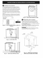
DiMENSiONES DELPRODUCTO
A
o o
D
20 1/8" I/
(51.1cm) J
3 11/16 wl
(9.4 cm)
C
17 lz/16wl
(45.2 cm)
1
Se muestra el modelo de 36 pulgadas
El modelo de 30 pulgadas es similar
23 3/8"
(59.4 cm)
Figura |
Estufade gas de 30 in 30 in(76,2 cm)
Estufade gas de 36 in 36 in (91,4cm)
Todas las dimensiones se indican en pulgadas (cm).
Dimensi6n en el centro de la estufa.
Impreso en los EE. UU.
2113/32in(54,4 cm)_ 26 13/16in(68,1cm)
2123/32in(55,1cm) 32 11/16in (83,0 cm)
1815/16in (48,1cm)
1815/16in (48,1cm)
316902922 (1206) Rev.B
Espa_ol - p6ginas 1-14

Notas importaintes para el iinstaiador
1. Lea toda la informaci6n contenida en estas
instrucciones de instalaci6n antes de instalar la
estufao
2. Retire de la estufa todo el material de
embalaje antes de conectar las alimentaciones
de gas y de electricidad a la estufa.
3. Cumpla con todos los c6digos y ordenanzas
que rigen en su Iocalidad.
4. AsegOrese de dejar estas instrucciones en
manos del propietario de la estufa.
5. Nora: si la estufa se opera a elevaciones
mayores de 2000 ft (600 m) par encima del
nivel del mar, se reduce la capacidad nominal
de la estufa en un 4 par ciento par cada 1000
ft (300 m) adicionales
Notas impartaintes para el prapietarlo de la estufa
Conserve estas instrucciones junto con la gu_a de usa
y cuidado para referencia en el futuro.
INSTRUCCIONES
IMPORTANTES PARA LA
SEGURIDAD
La instalaci6n de esta estufa debe hacerse en
conformidad con los c6digos vigentes en ta
localidad, yen caso de que no existan dichos
c6digos, en conformidad con el C6digo National
de Gas Combustible ANSI Z223.1/NFPA 54 si se
encuentra en los Estados Unidos, o en conformidad
con el C6digo Canadiense de Gas Combustible,
CAN/CGA B149 y CAN/CGA B149.2 si se
encuentra en Canad6.
* Cuando la instataci6n se haga en una casa
prefabricada (rodante), la instalaci6n se debe
hater en conformidad con ta norma fituto 24
CFR, parte 3280 de ta Manufactured Home
Construction and Safety, [anteriormente la
norma fituto 24, HUD (parte 280) det Federal
Standard for Mobile Home Construction
and Safety] o, cuando dicha norma no sea
pertinente, en conformidad con la norma ANSI/
NCSBCS A225.1 del Standard for Manufactured
Home Installation, o cuando corresponda, en
conformidad con los c6digos locales.
El diseho de esta estufa cuenta con ta certificaci6n
de los taboratorios Underwriters Laboratories (UL).
At igual que en todo electrodom6stico que utilice
gas y genere calor, existen varias precauciones de
seguridad que se deben cumptir. Las encontrar6
en la Guia de usa y cuidado, y debe leerlas
atentamente.
• Aseg_rese de que su estufa haya sldo iinstalada
y coinectada correctameinte a tlerra par uin
iinstalador o uin t_cinlco cali_cada de servlcla.
Esta estufa se debe conectar el_ctrlcameinte a
tlerra ein cainfarmidad coin los c6digas locales,
y en caso de que no existain dichas c6dlgas, ein
cainfarmidad coin la edlci6in m_s recleinte de la
norma ANSI/NFPA No. 70 del C6dlgo El_ctrlca
Nacianal estadauinldeinse sl se encueintra ein
los Estadas Uinldas, a ein cainfarmldad coin la
inorma CSA C22.1 Porte 1 del C6diga El_ctrlca
Cainadleinse sl se eincueintra ein Cainad_.
* Se puede enceinder manualmeinte los
quemadares ein case de clue se produzca ulna
iinterrupci6in del sumlinistra de electrlcldad.
Para einceinder mainualmeinte uincluemador de
superficie, acerque uinf6sfara einceindido al
cabezal del quemadar y luego lleve leintameinte
la perilla de control a la paslci6in LITE. Sea
culdadoso al einceinder mainualmeinte los
quemadares de superficie.
NO almaceine articulos que Ilamein
la ateinci6in de los hi,as ein gablinetes que se
eincueintrein einclma de la estufa. Los nihos podr_an
sufrir quemaduras graves si se trepan sabre
la estufa para alcanzar alga que les ltame la
atenci6n.
* A fin de elimiinar el riesga de quemaduras y
de incendias al calacar el cuerpa sabre los
cluemadores de superficie, se debe evitar la
iinstalaci6in de gablinetes de almaceinamleinta par
eincima de los quemadares.
" Ajuste el ramada de la llama del quemador de
superficle basra clue no se extleinda m_s all_
del horde del uteinsllla de caclna. Los llamas de
tamaho excesivo son petigrosas.
Nuinca utlilce la estufa para caleintar
el reclinta ein el que se eincueintra la estufa. El usa
protongado del estufa sin ventitaci6n adecuada
puede ser peligroso.
Almaceinamieinta ein el
electradam_stlco. No se debe almaceinar materlales
iinflamables cerca de las uinldades de superficle.
Dichos materiales incluyen arficutos de papel,
pl6stico y tela, coma libros de cocina, recipientes de
pl6stico y pahos, at igual que liquidos inflamables.
NO almacene en la estufa ni cerca de ella
materiales potencialmente explosivos, coma latas de
aerosol. Los materiales inflamables podr_an explotar
y causar incendios y dahos a bienes.
Se debe iinterrumplr el sumiinistra
de electricidad a la estufa cuaindo se est_in
hacienda las cainexiaines de la tuberia de gas.
Si no se cumple la iindlcaci6in anterior, pudlerain
acurrlr leslaines persainales groves y hasta la
muerte.

m6ximade
13in(33cm)
delgabinete
instalado
enla parte
superior
de la estufa.
18 in
(45,7 cm) (rain)
1 3/8in (3,5 cm) distancia minima
piana desde el borde del boquete.
Separaci6n minima de 30 in
(76,2 cm) entre la parte superior
de la plataforma de la estufa y
todo gabinete de madera o de
metal no protegido
Separacidn
24 in
...... 1 3/8in (3,5 cm) distancia minima
ol cm) _mm; plana desde el borde del boquete.
Figura :2- DISENO DEL GABINETE
I__ Para eiiminar ei riesgo de quemaduras y de incendios al coiocar ei cuerpo sobre superficies
caiienfes, se debe evitar ia instalaci6n de cjabinetes de aimacenamienfo situados encima de ia estufa.

Herramientas necesarias para la instalaci6n
- Destornillador de cruz
- Destornillador / Ilave de trinquete de 1/4"
- DestorniJJador / JJave de trinquete de 7/16"
Accesorios de sujeci6n suministrados
Cant. DescriF_ci6n Se utiliza en
(4)
(2)
Tuercas hexagonates de
7/16" con inserto de nailon
1/4-20
Tornitlo #10-24 de 3,5
in de longitud, de cruz
Soplador (fig. 20)
Soportes
(figs. 15 y 16)
Torniltos #8-18 de Ducto de transici6n(4) cabeza ancha, de cruz (fig. 18)
Tornillos #8-18 negros C6mara y cajetfn de
(6) 1/4" de cabeza hexagonal cables (figs. 17 y 21)
Encimera
(2) Soportes de sujeci6n (figs. 15 y 16)
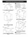
3
(8.3 cm)
q_
1 1II
(27.9 cm)
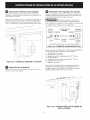
Ubicaci6n del tomacorriente de pared
Instale el tomacorriente de pared en la zona sombreada.
cL
I _1 11 1/2"
I_ 3/4-, (29.2 cm)
6" 8
(15.2 cm) (22.2 cm)
Figura 3B - DIMENSIONES DE INSTALACION DE LA
SALIDA ELECTRICADEL MODELO DE 30 PULGADAS
Suministre una alimentaci6n adecuada
de gas
Esta estufa est6 diseffada para funcionar exclusivamente con
gas natural a una presi6n en el mOltiple de 4 pulgadas de
columna de agua.
Se debe Jnstalar un reguJador de presi6n en
serie con el mOitJpie de [a estufa, y debe permanecer en serie
con la tuberfa de alimentaci6n.
Para un funcionamJento correcto, [a presi6n mc_xima en [a
admisi6n del regulador no debe ser superior a 14 pulcjadas
de columna de acjua.
Para inspeccionar el regulador, la presi6n en la admisi6n
debe ser de a[ menos 1 pulgada de agua (2,5 kPa) superior
al ajuste de la presi6n en el mOItiple del recjulador. Si el
recjulador est6 ajustado para una presi6n de 4 pulgadas en
el mOltiple, la presJ6n en la admisi6n del recjulador debe ser
de al menos 5 pulcjadas.
El di6metro de la tuberfa de alimentacJ6n de gas que va al
electrodom_stico debe ser de 1/2" o de 3/4".
Figura 3A - DIMENSIONES DE INSTALACION DE LA
SALIDA ELECTRICADFL MODFLO DE 36 PULGADAS

Conversi6n a gas licuado de petr61eo/
propano
Este electrodom6stico se puede utilizar con gas natural y
tambi_n con gas licuado de petr61eo/propano (GLP). Se
despacha de f6brica ajustado para el uso con gas natural.
Junto con la estufa se suministra un kit de conversi6n a GLP.
El kit est6 marcado "FOR LP/PROPANE GAS CONVERSION"
(para conversi6n a GLP/propano).
La conversi6n debe ser realizada por un t_cnico calificado de
servicio, yen conformidad con las instrucciones suministradas
con el kit, yen conformidad con todos los c6digos y
requerimientos locales. Si no se cumplen las instrucciones
anteriores, podrian producirse lesiones personales graves
y/o da_os a bienes. La agencia certificada que realice este
trabajo asume toda la responsabilidad de la conversi6n.
Si la conversi6n no se realiza correctamente,
podrfan ocurrir lesiones personales graves y da_os a bienes.
NOTA: compre una tuber{a flexible nueva. NO UTiLiCE
LA TUBERiA FLEXIBLE ViEJA USADA.
Importante: Retire de la estufa todo el material de embalaje
y el material impreso antes de conectar las alimentaciones
de gas y de electricidad a la estufa.
Ubicaci6n del nOmero del modelo y del
nOmero de serie
La placa del nOmero de serie se encuentra en la parte inferior
de la estufa.
AI hacer pedidos de piezas y al hacer consuitas acerca de su
estufa, no de]e de incluir los nOmeros del modelo y de serie y
tambi_n el nOmero o la letra del Iote de fabricaci6n, que se
indican en la placa del nOmero de serie de la estufa.
La placa del nOmero de serie tambi6n indica la capacidad
t6rmica nominal de los quemadores, el tipo de combustible y
la presi6n a la que se ajust6 la estufa en f6brica.
Requerimientos de la alimentaci6n de
electricidad
Circuito ramal de 120 Voltios, 60 Hertz con
correcta conexi6n a tierra, protegido por un disyuntor o
fusible de 15 A, con retardo. NO ufilice cables de extensi6n
en la alimentaci6n de electricidad de la estufa.
Instrucciones para la conexi6n a tlerra
IMPORTANTE Lea cuidadosamente esta informaci6n.
A efectas de la seguridad de las personas, la
estufa se debe canectar correctamente a tierra.
El cable de aNmentaci6n de electricidad de esta estufa est6
equipado con un enchufe de 3 patas (con conexi6n a tierra)
que se debe conectar a un toma¢orriente est6ndar de 3
patas con conexi6n a tierra (yea la figura 4), a fin de reducir
al mfnimo la posibilidad de peligros de descargas el_ctricas
en la estufa.
Un electricista calificado debe inspeccionar el tomacorriente
de pared y su cJrcuito, a fin de asegurarse de que el
tomacorriente cuente con una correcta conexi6n a tierra.
Si el Onico tomacorriente disponible es de 2 patas, el
propietario de la estufa estc] obligado yes personalmente
responsable de que un electricista calificado reemplace dicho
tomacorriente por uno de 3 patas, que tenga la polarizaci6n
correcta y que est_ conectado correctamente a tierra.
M_todo preferido
Tomacorriente
de pared con
conexi6n a
NINGUNA_
CIRCUNSTANCIA I
es permislble |
tartar, elimlnar o|
anular la pata de)
cone×i6n a tlerra. /
Cable de suministro de
electricidad con enchufe
de 3 patas con conexi6n
a tierra
Figura 4
BAJO NINGUNA CIRCUNSTANCIA, es permisible tartar,
eliminar o anular la pata de conexi6n a fierra del enchufe
del cable de alimentaci6n de electricidad.
_ Desconecte del tomacorriente de pared el
cable de alimentaci6n de electricidad antes de realizar toda
tarea de servicio en la estufa.
Posicionamiento de la estufa
El ativio de escape de la estufa se debe colocar entre dos vigas de
pared o entre dos travesa_os de piso, a efectos de la instataci6n
correcta de la ducterfa.
Preparaci6n del gabinete base
Esta estufa est6 dise_ada para encajar f6cilmente en gabinetes de
distintos tipos. No obstante, atgunos gabinetes podrfan requerir de
modificaciones.
Preparaci6n de un gabinete que tenga
gavetas
Si el gabinete tiene gavetas, se debe desmontar y desarmar las
cjavetas, y fijar las caras de las cjavetas a la parte detantera det
cjabinete.
Mida la Iongitud y el ancho internos del gabinete base.
En atgunos tipos de gabinetes, podr_a ser necesario hacer cortes en
las paredes taterates y/o en ta pared trasera, y/o eliminar tambi_n
los esquineros a fin de poder instatar la estufa.
Boquete en la enclrnera
La superficies de las encimeras provistas de un borde delantero
redondeado y de una curva en ta base det satpicadero trasero
podrfan no tenet et tamafio necesario para la instataci6n de la
estufa.
Carte el boquete en la encimera en conformidad con tas
dimensiones que se indican en la figura 2. El boquete se debe cortar
perpendicutarmente y con los lados en paraleto entre etlos, con los
lados delantero y trasero perpendiculares a los lados izquierdo y
derecho.

lnstalaci6n de la ducteria
Utilice ductos redondos de atuminio o de metal cjatvanizado, de
6 o de 31/4pulcjadas de di6metro y de 10 pulcjadas de loncjitud, o
una combinaci6n de ambos. Se debe utitizar ductos de PVC si se
instalan debajo de ptacas de concreto vaciado. Coloque ta ducteHa
de modo que sea Io m6s corta y recta posibte. Para un desempe_o
satisfactorio, la loncjitud equivatente de ta ducterfa no debe set
mayor de 100 ft (30 m). Consutte el cjr6fico de '"C6tculo de ta
Ioncjitud de la ducterfa" para conocer tas loncjitudes equivalentes.
(vea la p6cjina 14). Todas uniones entre ductos deben estar sujetas
con un tornitlo y settadas con cinta para ductos, como se muestra en
la flcjura 5.
NOTA: se debe cumptir con los c6dicjos de construcci6n locales al
especiflcar el tipo aprobado y las especiflcaciones de TODOS los
ductos que se utilicen. Siempre utilice un casquete adecuado para
pared o techo, provisto de amorticjuador.
Cinta de ductos •
sobre la uni6n -- /Tornilloy el tornillo _/
/
Flujo de
.
Figura 5 - CINTA DE DUCTOS SOBRE LA UNION Y EL
TORNILLO
Figura 8 - DUCTO QUE ATRAVIESA LA PARED
Preparaci6n para la ducteria
Corte un orificio en la pared o en el piso del cjabinete, secj0n
corresponda, en funci6n de las caracteHsticas det tucjar de
instataci6n. Asecj0rese de que et ducto de escape se encuentre
entre dos vicjas de pared o entre dos travesa_os de piso, secjOn
corresponda. (Ficjuras 9, 10, 11, 12, 13A y 13B) NOTA: la descarcja de
la ducterfa DEBE SER at exterior.
BAJO NINGUNA CIRCUNSTANCIA, es permisible que ta ducterfa
descarcjue at interior de una pared, a un techo, a un espacio libre
entre pisos o paredes, a un 6tico o a un recinto oculto.
ql o , . o
'l_J'
\/i
%
...I/_
_AI hacer cortes o perforaciones en una pared
o en un techo, EVlTE causar da5os a cables et_ctricos y a otras
instataciones en et interior de la pared o det techo.
CENTRO
DE BOQUETE
CENTRO
DE BOQUETE
/
//
Figura 6 - DUCTO EN EL PISO
Figura 9 - MODELO DE 30 PULGADAS
Figura 7 - DUCTO QUE ATRAVIESA EL PISO ORIFICIO DE LA DUCTERiA EN EL FONDO
6

CENTRO
DE BOQUETE
CENTRO
DE BOQUETE
Figura 10 - MODELO DE 30 PULGADAS ORIFiCiO
DE LA DUCTERIA EN LA PAREDTRASERA
CENTRO
DE BOQUETE
CENTRO
DE BOQUETE
Ducteria aJterna
En el caso de JnstaJaciones en
ias que haya restri¢cJones de
espacio que no perrnJtan orientar
el sopJador para ¢onectarJo a
ia ducterfa, estc_ disponible eJ
kit 5304488297. Se muestran
ias dimensiones para ubicar Ja
abertura para eJ ducto cuando se
utiliza este kit de adaptaci6n.
CENTRO
DE BOQUETE _
I
I
Figura 13
KiT DE DUCTO ALTERNO
DE TRANCISION
_ _ 6 3/8"
_ _ (16.2 cm)
22 5/8" _
(57.5 cm)
(15.2 cm)
i
i
Figura 11- MODELO DE 36 PULGADAS
ORIFICIO DE LA DUCTERiA EN ELFONDO
CENTRO
DE BOQUETE
I
[_ I/4" (0,6 cm)
Figura 12- MODELC) DE 36 PULGADAS
ORIFICIO DE LA DUCTERIA DEL LADO IZQUIERDO O
DERECHO
Figura 13A - ORJFICIO ALTERNO DE LA
DUCTERJA, MODELO DE 30 PULGADAS
CENTRO
DE BOQUETE
8 7/8 H
22 s/8"
(57.5 cm)
(15.2 cm)
Figura 13B- ORiFiCIO ALTERNO DE LA
DUCTERiA, MODELO DE 36 PULGADAS
Aire de reposlci6n
Los c6digos locales de construcci6n podrfan exigir el uso de
sistemas de aire de reposici6n. Consulte los c6digos IocaJes a fin
de determinar los requerimientos especfficos de aire de reposici6n
correspondientes a su instalaci6n.

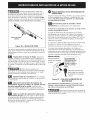
Alineaci6n del soplador y la ducteria
No se sugiere et uso de ductos flexibles dado que pueden restrincjir
en gran medida el flujo de aire. Si la satida del soplador y el ducto
en el suelo o en ta pared NO est6n atineados, se puede utilizar
ductos flexibtes de METAL para compensar por la desviaci6n.
con la parte trasera de ta encimera. A fin de prevenir da_os a la
encimera, EVITE apretar en exceso et tornillo.
Desviaci6n
MAXIMA de
6 in entre
las Iineas
centrales
Figura 14 - ALINEACI6N DE LA DUCTERiA
Instalaci6n de la estufa
Eleve ta estufa pot sus bordes laterales como se muestra.
Haga descender la estufa en el boquete de ta encimera, y cot6quela
cuidadosamente en su posici6n correcta. Apoye la estufa en su parte
inferior y h6gata descender lentamente. Retire cuidadosamente los
dedos de debajo de la estufa una esquina a la vez, para terminar
de cotocar la estufa.
NOTA: NO utilice compuestos RTV de siticona ni compuestos de
catafateo para sellar la uni6n entre la estufa y la encimera.
Un soF
sujeci6n
tornillos #8-18 negros de
] cabeza hexagonal sujetos a la
Un tornillo estufa
argo, de cruz EI
Figura 16 - FIJE LOS DOS SOPORTES
ESTUFA DE GAS
Tornillos
scsumlnistrados
con la estufa de cruz
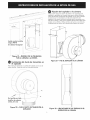
Figura 17 - SOPORTES DE INSTALACI6N
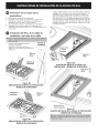
Instalaci6n de la cbmara del soplador en
Ja estufa
Con la abertura del soplador en el lado derecho, deslice la c6mara
en ta abertura que se encuentra en la parte inferior de la estufa.
Haga presi6n hacia arriba sobre la c6mara hasta que los rieles
de instalaci6n que se encuentran a los lados de la c6mara hagan
contacto con la parte inferior de la estufa. Instate cuatro tornittos de
#8 x 3/8" de fljaci6n de 16minas de metal para sujetar la c6mara
en su sitio.
Figura 15- DESCENSO DE LA ESTUFA EN EL
BOQUETE DE LA ENCIMERA
lnstalaci6n de los soportes de sujeci6n
Quite los tornitlos que se encuentran en el bastidor de la estufa y
utilfcetos para fljar el soporte de suieci6n a la parte inferior del
bastidor. Inserte et tornillo en et soporte hasta que hacja contacto
Instale cuatro tornillos negros
#8-18 de cabeza hexagonal
Figura 18- MODELO DE 30 PULGADAS
FUE LA CAMARA A LA ESTUFA

.... _s_ -__ ............
i_ _ _
I
Instale cuatro tornillos
necjros #8-18
de cabeza he×acjonal
I
I
I
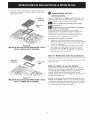
Fijaci6n del soplador a la c_mara
Instale cuatro tuercas de inserto de nailon en los esp6rragos del
soptador, y apri_telas con ta mano hasta que se sienta resistencia.
Atinee la abertura de descarga det soptador con el ducto. Cotoque
las tuercas que se encuentran a un lado del atojamiento det
soptador en los cuatro orificios de montaje que se encuentran a un
lado de la c6mara, y deje que et soptador deslice hacia abajo para
encajar en los orificios. Utitice una llave de tuercas o una Itave de
trinquete desde et interior de la c_mara para apretar las tuercas.
.L.......F_gura 19 - MODELO DE 36 PULGADAS
FIJE LA CAMARA A LA ESTUFA
Instalaci6n del ducto de transici6n en
el soplador
Fije el ducto de transici6n a la satida det soplador con el uso de
cuatro tornillos. Rodee la uni6n con cinta para settarta.
Figura 21 - FiJF FLSOPLADOR A LA CAMARA
Figura 22 - UBiCACIONES D_ LAS TU_:RCASFN FL
iNT_:RiOR DF LA CAMARA

Conexiones el_ctricas del soplador
Conecte el enchufe de 5 ctavijas del conjunto del soptador at
recept6cuto correspondiente de 5 orificios que seencuentra en la
parte inferior de la estufa.
Pliegue todos los cables en el interior det cajefin de cableado que
se encuentra en el extremo del tubo conduit del soptador. Fije el
cajetfn de cableado a la estufa con et uso de dos tornitlos #8 x
3/8"t y compruebe que no haya quedado atrapado ningOn cable,
Instalaci6n del regulador de presi6n
Instale el regulador de presi6n con la flecha marcada en el
regulador apuntando hacia la estufa, en una posici6n en la
que se alcance f_cilmente la tapa de acceso.
_NO apriete en exceso la conexi6n. El
cuerpo deJ reguiador es de fundici6n. El apriete excesivo
podr[a agrietar el regulador, Io que causar[a una fuga de gas
y el peNgro de un incendio o de una explosi6n.
Figura 23 - CONECTE ELSOPLADOR A LA ESTUFA
Conexi6n de la ducteria
Conecte ta ducterfa que fue preparada en los pasos 8, 9 y 10 at
ducto de transici6n det soplador.
V&lvula FLUJO DE GAS Regulador
de corte de presi6n
manual Adaptador Adaptador
T r,
de
Cerrada flexible .a_,a
acceso
Ajuste todas las uniones con una llave inglesa
Figure 24 -TUBERJA DEALJMENTACJONDEGAS
Conecte el conector flexible de la tuber[a de alimentaci6n de
gas al regulador en la secuencia a continuaci6n..
1. v_lvula manual de torte
2. empalme de 1/2" (1,3 cm)
3. adaptador de uni6n abocardada de 1/2" (1,3 cm)
4. conector flexible
5. adaptador de uni6n abocardada de 1/2" (1,3 cm)
6. empalme de 1/2" (1,3 cm)
7. regulador de presi6n
Para sellar las conexiones de los componentes, utilice un
¢ompuesto de uni6n de tuber[as adecuado para el uso
con gas natural y GLP/propano. Si se utilizan ¢onectores
flexibles r aseg0rese de evitar que se tuerzan.
Figura 25 - CONEXI6N FtSICA DE LA TUBER{A DE
GAS A LA ESTUFA
10

_J_]]__ La tuberfa de aJimentaci6n debe estar
provista de una v61vula manual de corte que cuente con las
aprobaciones pertinentes. Dicha v61vula se debe instalar
en el mismo recinto en el que se encuentra la estufa, en un
lugar que permita su apertura y cierre con facilidad. FVIT_:
bloquear el acceso a la v61vula de corte. La funci6n de dicha
v61vula es permitir o cortar el flujo de gas a la estufa.
Valvula de corte -
Abierta _
Figura 26 - VALVULA DE CORTE
Una vez que est8 instalado el regulador, abra la v61vula de
corte que se encuentra en la tuberfa de aJimentaci6n de gas.
Espere algunos minutos a que el gas se desplace a travSs de
la tuberfa.
Jnspecclone en busca de fucjas. Despu6s de
conectar la estufa a la alimentaci6n de gas, inspeccione el
sistema en busca de fugas, con el uso de un man6metro. Si no
est6 disponible un man6metro, abra la alimentaci6n de gas y
utilice un ffquido detector de fugas (o agua y jab6n) en todas
las uniones y conexiones a fin de inspeccionarlas en busca de
fugas.
_NO utilice llamas abiertas para
inspeccionar las conexiones y las uniones en busca de fugas.
Si se utiliza una llama abierta para inspeccionar la tuberfa
podHa producirse un incendio o una explosi6n.
| Aprlete todas las conexlones de ser necesario
a fin de prevenir fugas de gas en la estufa y/o en la tuber[a
de alimentaci6n.
alpine Desconecte del slstema de tuberias de
ntaci6n de gas la estufa y la v_ivula manual
de torte especifica de Ja estufa al realizar toda
prueba de presi6n de dicho sistema a presiones de prueba
superiores a 1/2 psig (3,5 kPa o 14 pulgadas de columna de
agua).
Aisle la estufa deJ sistema de tuberias de
allrr_erltaci6n de gas; para ello cierre la v6Jvula manual
de corte especffica de la estufa aJ reaHzar toda prueba de
presi6n dei sistema de tuberfas de aNmentaci6n de gas a
presJones de prueba iguales o menores de I/2 psig (3,5 kPa o
14 puigadas de coiumna de agua).
Requerimienfos de la alimenfaci6n de
elecfricidad
Circuito ramal de 120 Voltios, 60 Hertz con correcta conexi6n
a tierra, protegido por un disyuntor o fusible de 15 A, con
retardo. NO utilice cables de extensi6n en la alimentaci6n
de elec/ricidad de la estufa.
Instrucciones para la conexi6n a tlerra
IMPORTANTE Lea cuidadosamente esta informaci6n.
A efec/os de la seguridad de las personas, la estufa se debe
conectar correctamente a fierra.
El cable de alimentaci6n de electricidad de esta estufa
est6 equipado con un enchufe de 3 patas (con conexi6n a
tierra) que se debe conectar a un tomacorriente est6ndar
de 3 patas con conexi6n a tierra (vea la flgura 27), a fin de
reducir al mfnimo la posibilidad de peligros de descargas
el_ctricas en la estufa.
Un electricista calificado debe inspeccionar el tomacorriente
de pared y su cJrcuito, a fin de asegurarse de que el
tomacorriente cuente con una correcta conexi6n a tierra.
Si el 6nico tomacorriente disponible es de 2 patas, el
propJetario de la estufa est_ obligado y es personalmente
responsable de que un electricista calificado reemplace dicho
tomacorriente por uno de 3 patas, que tenga la polarizaci6n
correcta y que est6 conectado correctamente a tierra.
M_todo preferldo
Tomacorriente de NINGUNA
pared con conexi6n CIRCUNSTANCiAes
a tierra permisible cortar,
eliminar o anular la
pata de conexi6n a
erra.
Cable de suministro de
eiectricidad con enchufe
de 3 patas con conexi6n
a tierra
Figura 27 - CABLE DE ALIMENTACI6N DE
ELECTRICIDAD
BAJO NINGUNA CIRCUNSTANCIAes permisible cortar,
eliminar o anular la pata de conexi6n a fierra del enchufe
del cable de alimentaci6n de electricidad.
_ Desconecte del tomacorriente de pared el
cable de alimentaci6n de electricidad antes de realizar toda
tarea de servicio en la estufa.
11

A.
B.
C.
D.
Instalaci6n de las tapas de los
quernadores
Desembale las rejillas de los quemadores.
Quemadores: Desembate los cabezales y las tapas de los
quemadores. Coloque los cabezates y las tapas de los
quemadores sobre sus bases correspondientes.
Las tapas deben quedar a nivel despu_s de su instataci6n
AsegOrese de que todas las tapas y los cabezales de los
quemadores est_n correctamente en su sitio ANTES de porter en
uso la estufa
Instalaci6n del Nitro, de la rejilla de
ventilaci6n y del seilo de la rejilla
Coloque el fittro diagonatmente en la
c6mara de ventitaci6n.
Aseg0rese de que quede apoyado_ en
6ngulo, sobre los soportes de la abertura de
ventilaci6n.
Filtro de
f grasa
\
Figura 28 ...................
UBICACI6N DEL FtLTRO DE LA VENTILACI6N -
MODELO DE 30 PULGADAS
Coloque cuidadosamente el selto de la rejitla sobre la c6mara de
ventilaci6n de la estufa, como se muestra en las tlguras 30 - 31.
AsegOrese de que el cottarfn que se encuentra en el fondo del
selto quede totatmente insertado en ta abertura de ventilaci6n.
Quite el tornilto de 1/4" de cabeza hexagonal que se encuentra
en la c6mara de ventilaci6n, debajo de la pesta_a det setlo de ta
rejilta de ventitaci6n. Doble la pesta_a del sello de la rejitla de
ventitaci6n hacia la c6mara de ventitaci6n_ y fijela con et tornilto
de cabeza hexagonal.
Figura 30
FIJACI6N DEL SELLODE LA REJILLA DE
VENTILACI6N - MODELO DE 30 PULGADAS
Sello de la
rejilla
Tornillo #8=18 de
cabeza hexagonal
Figura 31
FIJACI6N DEL SELLODE LA REJILLA DE VENTtLACI6N
- MODELO DE 36 PULGADAS
Figura 29
UBICACI6N DEL FILTRO DE LA VENTILACI6N -
MODELO DE 36 PULGADAS
12

* Cotoque la rejilla de ventilaci6n sobre el sello de ta rejitla, sobre
la abertura de ventilaci6n. Coloque las rejitlas de los quemadores
sobre los quemadores.
ilia de
ventilaci6n
Figura 32
UBICACI6N DE LA REJILLADE VENTILACI6N Y DE SU
SELLO- MODELO DE 30 PULGADAS
Comprobaci6n del buen
funcionamiento
Consulte la Guia de uso y cuidado suministrada junto con la
estufa a fin de conocer las instrucciones de operaci6n y la
informaci6n de ¢uidado y limpieza de la estufa.
Active el sumlnistro de electricidad y abra la v61vula
principal de torte de gas
_'_ Cornprobaci6n del correcto funclonamiento del sistema de
chlspas el6ctrlcas de los quemadores
Se debe inspeccionar el funcionamiento del sistema de
chispas el@ctricas de los quemadores despu@s de inspeccionar
cuidadosamente tos conectores en la estufa yen ta tuber{a
de atimentaci6n en busca de fugas, y despu@s de que se haya
conectado la estufa a la alimentaci6n de electricidad.
Operaci6n de los quemadores de superflcle:
A. Haga presi6n sobre la peritta del quemador de superflcie y
II@veta a la posici6n LITE (encender). Se escuchar6 un ruidito de
tic tic. Es el sonido del sistema de generaci6n de chispas que
enciende los quemadores.
B. Una vez que el quemador haya encendido, ajuste la perilla
hasta obtener et tama_o deseado de la llama. La posici6n
de la peritla de control NO tiene que estar en un punto en
particular. Utilice la posici6n det indicador de la perilla para
ajustar la llama seg0n sea necesario.
de la
rejilla
Figura 33
UBICACI6N DE LA REJILLADE VENTILACI6N Y DE SU
SELLO- MODELO DE 36 PULGADAS
Una vez finalizadas todas las conexiones
AsegOrese de que todos los controtes se encuentren en la posici6n OFF.
AsecjOrese de que et flujo de gas combustible y de aire en la estufa no
tencja obstrucciones.
Antes de liamar al servicio t6cnico
Lea la lista de comprobaci6n "Antes de Ilamar al servicio
t@cnico" y las instrucciones de operaci6n que se encuentran
en la Guia de usa y cuidada. Podr[a ahorrarle tiempo
y dinero. La Iista incluye situaciones comunes en este
electrodom6stico que no son el resultado de mano de obra ni
de materiales defectuosos.
Consulte la informaci6n de garant[a que se encuentra en la
Guia de uso y cuidado a fin de conocer el nOmero telef6nico
y la direcci6n de nuestro departamento de servicio. LI6menos
o escribanos si tiene alguna consulta acerca de su producto
y/o si necesita hacer un pedido de piezas.
13

C61culo de ia tabla de iongitud de la ducteria
Para una m6xima eflciencia0 coloque ta ducteHa de modo que sea 1o m6s corta y recta posible. Utitice la menor cantidad
de acoptes que sea posible. Para un 6primo desempeffo, la loncjitud equivatente de la ducterfa no debe set mayor de
100 ft (30 m).
Los c6tculos son aproximados y se basan en los est6ndares de la industria del aire acondicionado y la catefacci6n.
LONGITUD CANTIDAD LONGITUD
SEGMENTOS DE DUCTO
EQUIVALENTE X UTILIZADA -- EQUIVALENTE
6 in (15,2 cm) de di6metro, recto 1 ft (0,3 m) fto m
de metal flexible de 6 in (15,2 cm) de
1,5
ft
(O,45m)
ft o m
di6metro, sin dobteces **
(_ Codo de 6 in (15,2 cm), de 90 ° 10 ft (3 ft
m)
o m
(_ Codo de 6 in (15,2 cm), de 45 °
5 ft
(1,5m)
ft o m
[__ 31/4" x 10 in (8,2 cm x 25,4 cm)recto ** 1 ft (0,3 m) ft o m
Codo de 31/4 '' x 10 in
(8,2 cm x 25,4 cm), de 90 ° 10 ft (3 m) fto m
Codo de 31/4 in x 10 in
(8,2 cm x 25,4 cm), de 45 ° 5 ft (1,5 m) fto m
Codo piano de 31/4 in x 10 in
(8,2 cm x 25,4 cm), (3 m) o m
de 9O ° 10 ft ft
Codo redondo de transici6n de 31/4 in
x 10 in (8,2 cm x 25,4 cm) a 6 in (15,2
cm), de 90 ° 30 ft (9 m) fto m
[_ Codo de 6 in (15,2 cm) redondo a 31/4
in x 10 in (8,2 cm x 25,4 cm), de 90 ° 30 ft (9 m) ft o m
Codo redondo de transici6n de 31/4 in
x 10 in (8,2 cm x 25,4 cm) a 6 in (15,2 5 ft (1,5 m) ft o m
cm)
Codo de transici6n de 6 in (15,2 cm)
redondo a 31/4'' x 10 in 5 ft (1,5 m) fto m
(8,2 cm x 25,4 cm)
Tapa redonda de pared de 6 in (15,2
3O ft
(9 m)
ft o m
cm), con amortiguador
[_ Tapa de pared con amortiguador, de
31/4 in x 10 in (8,2 cm x 25,4 cm) 30 ft (9 m) fto m
Tapa redonda para techo de 6 in (15,2
cm) 30 ft (9 m) ft o m
DUCTERiA TOTAL fto m
** En el caso de ductos rectos de secci6n rectangutar/redonda, mida ta
Iongitud lineal real de la ducterfa y luego multiptiquela pot la tongitud
equivalente que se indica.
14
-
 1
1
-
 2
2
-
 3
3
-
 4
4
-
 5
5
-
 6
6
-
 7
7
-
 8
8
-
 9
9
-
 10
10
-
 11
11
-
 12
12
-
 13
13
-
 14
14
-
 15
15
-
 16
16
-
 17
17
-
 18
18
-
 19
19
-
 20
20
-
 21
21
-
 22
22
-
 23
23
-
 24
24
-
 25
25
-
 26
26
-
 27
27
-
 28
28