
Kurz-
beschreibung
Brief description
Mehrachs-
interface
Multi-axis
interface
CPX-CMXX
–Deutsch
– English
–Español
–Français
– Italiano
–Svenska
757 650
1102b
CPX Terminal

Festo CPX-CMXX 1102b2
Deutsch 3...........................................
English 15............................................
Español 27...........................................
Français 39...........................................
Italiano 51............................................
Svenska 63...........................................
TORX
®
ist ein eingetragenes Warenzeichen des jeweiligen
Herstellers in gewissen Ländern.
Edition: 1102b
Original: de
© (Festo SE & Co. KG, D-73726 Esslingen, Germany, 2011)
Internet: http://www.festo.com
E-Mail: [email protected]

Festo CPX-CMXX 1102b Deutsch
3
Deutsch - Mehrachsinterface CPX-CMXX
Das Mehrachsinterface CPX-CMXX ist ausschließlich zum
Einsatz in CPX-Terminals bestimmt und dient bestim-
mungsgemäß zur Koordination von Antriebseinheiten von
Festo. Hierbei sind die angegebenen Grenzwerte der tech-
nischen Daten einzuhalten.
Ausführliche Informationen finden Sie in der Beschreibung
zum CPX-CMXX (P.BE-CPX-CMXX-...) sowie in der CPX-
Systembeschreibung (P.BE-CPX-SYS-...).
Warnung
S Schalten Sie die Spannung aus, bevor Sie Steckver-
binder zusammenstecken oder trennen (Funktions-
schädigung).
S Verwenden Sie nur Netzteile, die eine sichere elektri-
sche Trennung der Betriebsspannung nach IEC 742/
EN 60742/VDE 0551 mit mindestens 4 kV Isolations-
festigkeit gewährleisten (PELV). Schaltnetzteile sind
zulässig, wenn sie die sichere Trennung im Sinne der
EN 60950/VDE 0805 gewährleisten.
S Schließen Sie einen Erdleiter mit ausreichendem
Leitungsquerschnitt an den mit dem Erdungssymbol
gekennzeichneten Anschluss des CPX-Terminals an.
S Das CPX-CMXX enthält elektrostatisch gefährdete
Bauelemente. Berühren Sie deshalb keine Bauele-
mente. Beachten Sie die Handhabungsvorschriften
für elektrostatisch gefährdete Bauelemente.
Hinweis
Nehmen Sie nur ein komplett montiertes und
verdrahtetes CPX-Terminal in Betrieb.

Festo CPX-CMXX 1102b Deutsch
4
1 Anschluss- und Anzeigeelemente
1 Status-LEDs
2 RUN/STOP-
Drehschalter
3 Ethernet-
Schnittstelle
4 Control-Interface
(CAN-Bus, 9-poliger
Sub-D Stecker)
5 DIL-Schalter 1
6 DIL-Schalter 2
7 keine Funktion
1
2
4
3
5
6
7

Festo CPX-CMXX 1102b Deutsch
5
Status-LEDs
1 RUN
1)
CPX-CMXX gestartet
(grün)
2 STOP
1)
CPX-CMXX gestoppt
(gelb)
3 ERROR Fehler
(rot)
4 TP Ethernet-Verbindung
(grün)
5 M Steuerhoheit liegt
bei FCT
(gelb)
6 PS Power System
(grün)
1
2
3
4
5
6
1)
Die LEDs RUN 1 und STOP 2 zeigen den Zustand des RUN/STOP-
Drehschalters.

Festo CPX-CMXX 1102b Deutsch
6
2 Installationshinweise
Warnung
Schalten Sie vor Installations- und Wart ungsarbeiten
Folgendes aus:
– ggf. Druckluftversorgung
– Betriebsspannungsversorgung Elektronik/Sensoren
– Lastspannungsversorgung Ausgänge/Ventile
2.1 Montage/Demontage
Das Mehrachsinterface CPX-CMXX ist in einen Verkettungs-
block des CPX-Terminals montiert .
1 Schrauben,
TORX T10
Anziehdrehmoment
0,9 … 1,1 Nm
2 CPX-CMXX
3 Stromschienen
4 Verkettungsblock
(beliebig, hier
beispielhaft ohne
Einspeisung)
3
1
2
4

Festo CPX-CMXX 1102b Deutsch
7
Demontage
1. Lösen Sie die 4 Schrauben 1 des CPX-CMXX 2 mit
einem TORX-Schraubendreher Größe T10.
2. Ziehen Sie das CPX-CMXX 2 vorsichtig und ohne zu
verkantenvondenStromschienen3 des Verkettungs-
blocks 4 ab.
Montage
1. Setzen Sie das CPX-CMXX 2 in den Verkettungsblock
4 ein. Achten Sie darauf, dass die entsprechenden
Nuten mit den Klemmen zur Kontaktierung auf der
Unterseite des CPX-CMXX 2 über den Stromschienen
3 liegen.
2. Drücken Sie dann das CPX-CMXX 2 vorsichtig und
ohne zu verkanten bis zum Anschlag in den
Verkettungsblock 4.
3. Setzen Sie die Schrauben 1 so an, dass die
vorgefurchten Gewindegänge genutzt werden.
Drehen Sie die Schrauben 1 nur von Hand ein.
4. Ziehen Sie die Schrauben 1 mit einem TORX-
Schraubendreher Größe T10 mit 0,9 … 1,1 Nm an.

Festo CPX-CMXX 1102b Deutsch
8
2.2 Einstellen der DIL-Schalter
Stellen Sie die Betriebsart mit dem DIL-Schalter 1 ein:
Betriebsart
DIL-Schalter 1
CMXX DIL 1.1: OFF
DIL 1.2: ON
Alle weiteren Schalterstellungen sind reserviert.
Hinweis
Prüfen Sie die korrekte Einstellung des DIL-Schalters
bevor Sie das CPX-CMXX in Betrieb nehmen. Eine
Änderung der Schalterstellung wird erst nach Aus- und
Einschalten der Spannungsversorgung erkannt.

Festo CPX-CMXX 1102b Deutsch
9
Schalten Sie die CAN-Bus Terminierung mit dem
DIL-Schalter 2 ein bzw. aus:
CAN-Bus Terminierung, 120 Ω
DIL-Schalter 2
Terminierung ausgeschaltet DIL 2.1: OFF
DIL 2.2: OFF
Terminierung eingeschaltet DIL 2.1: ON
DIL 2.2: OFF
Alle weiteren Schalterstellungen sind reserviert.

Festo CPX-CMXX 1102b Deutsch
10
2.3 Einstellen des RUN/STOP-Drehschalters
Hinweis
Lassen Sie den RUN/STOP-Drehschalter während der
Installation auf Position “0” (STOP) stehen.
Einstellung
Drehschalter
0=STOP
CPX-CMXX wird gestoppt bei Änderung des
RUN/STOP-Drehschalters von 1 … F auf 0.
Die Stop-LED leuchtet gelb.
1…F=RUN
CPX-CMXX gestartet. Die RUN-LED leuchtet
grün. Die Schalterstellungen 1 … F haben keine
weitere Funktion.
Änderungen der RUN/STOP-Drehschalter-Position werden mit einer
Verzögerung von 500 ms an die Steuerung weitergegeben.

Festo CPX-CMXX 1102b Deutsch
11
2.4 Pin-Belegung Control-Interface
Die Antriebsregler des Mehrachssystems werden über
CAN-Bus am Control-Interface des CPX-CMXX ange-
schlossen.
Stecker
Pin Signal Interne
Kontak-
tierung
Erläuterung
51
96
1
2
3
4
5
6
7
8
9
Gehäuse
(Stecker)
n.c.
CAN_L
CAN_GND
n.c.
CAN_SHLD
CAN_GND
CAN_H
n.c.
n.c.
FE
nicht angeschlossen
CAN Low
CAN Ground
nicht angeschlossen
Verbindung zur FE
2)
CAN Ground (optional)
1)
C A N High
nicht angeschlossen
nicht angeschlossen
Das Gehäuse des Steckers
ist an FE
2)
anzubinden.
1)
Wird ein Antriebsregler mit externer Spannungsversorgung ange-
schlossen, so darf CAN Ground (optional), Pin 6, am CPX-CMXX nicht
verwendet werden.
2)
FE: Funktionserde
Das CPX-CMXX stellt den angeschlossenen CAN-Bus-
Teilnehmern über das Control-Interface keine Spannungs-
versorgung zur Verfügung.

Festo CPX-CMXX 1102b Deutsch
12
2.5 Pinbelegung der Ethernet-Schnittstelle
Die Ethernetschnittstelle ist nur zur Konfiguration und
Parametrierung des CPX-CMXX vorgesehen.
RJ45-Buchse
Pin Signal Erläuterung
1
2
3
4
5
6
7
8
1
2
3
4
5
6
7
8
Metall-
umhüllung
TD+
TD–
RD+
n.c.
n.c.
RD–
n.c.
n.c.
Shield
Sendedaten+
Sendedaten–
Empfangsdaten+
nicht angeschlossen
nicht angeschlossen
Empfangsdaten–
nicht angeschlossen
nicht angeschlossen
Schirm

Festo CPX-CMXX 1102b Deutsch
13
2.6 Spannungsversorgung des CPX-CMXX
Die Spannungsversorgung für das CPX-CMXX wird über
den Verkettungsblock zugeführt.
– Das CPX-CMXX wird über die Betriebsspannungs-
versorgung für Elektronik und Sensoren versorgt.
– Die Lastspannungsversorgung für Ventile und digitale
Ausgänge wird nicht benötigt.
Das CPX-CMXX kann somit mit allen Verkettungsblöcken
kombiniert werden.
– Verkettungsblock ohne Einspeisung
– Verkettungsblock mit Systemeinspeisung, wenn der
Platz unterhalb der Module links vom CPX-CMXX für
die Systemeinspeisung nicht ausreicht.
– Verkettungsblock mit Zusatzeinspeisung, wenn das
Moduls rechts vom CPX-CMXX eine Zusatzeinspeisung
benötigt, aber der Platz für die Zusatzeinspeisung
nicht ausreicht.
Hinweis
Weitere Informationen zur Spannungsversorgung und
den Verkettungsblöcken finden Sie in der CPX-System-
beschreibung P.BE-CPX-SYS-...

Festo CPX-CMXX 1102b Deutsch
14
3 Technische Daten
Typ CPX-CMXX
Allgemeine Technische Daten
zum CPX-Terminal
siehe CPX-Systembeschreibung:
– P.BE-CPX-SYS-...
Weitere Technische Daten zum
CPX-CMXX
siehe CPX-CMXX-Beschreibung
– P.BE-CPX-CMXX-...
Schutzart
– nur in Verbindung mit Steckern
und Abdeckungen in Schutzart
IP65/67
IP65/IP67
Nennbetriebsspannung 24 VDC
Betriebsspannungsbereich 18 … 30 VDC
Eigenstromaufnahme
– bei Nennbetriebsspannung
typ. 85 mA
Netzausfallüberbrückung 10 ms
Produktgewicht 155 g

Festo CPX-CMXX 1102b English
15
English - Multi-axis interface CPX-CMXX
The multi-axis interface CPX-CMXX has been designed
exclusively for use in CPX terminals and serves for
coordinating drive units from Festo. The maximum values
specifiedinthesection“Technical specifications” must be
observed here.
Detailed information can be found in the manual for the
CPX-CMXX (P.BE-CPX-CMXX-...) as well as in the CPX
system manual (P.BE-CPX-SYS-...).
Warning
S Switch off the power supply before connecting or
disconnecting plugs (otherwise this could lead to
functional damage).
S Use only power units which guarantee reliable
isolation of the operating voltage as per IEC 742/
EN 60742/VDE 0551 with at least 4 kV isolation
resistance (Protected E xtra Low Voltage PELV). Switch
power packs are permitted, providing they guarantee
reliable isolation as per EN 60950/VDE 0805.
S Connect an earth conductor of sufficient cross-
sectional area to the connection on the CPX terminal
marked with the earth symbol.
S The CPX-CMXX contains electrostatically sensitive
components. Do not therefore touch any contacts.
Observe the handling specifications for electrostati-
cally sensitive components.
Please note
Commission only a CPX terminal which has been fitted
and wired completely.

Festo CPX-CMXX 1102b English
16
1 Connecting and display elements
1 Status LEDs
2 RUN/STOP rotary
switch
3 Ethernet interface
4 Control interface
(CAN bus, 9-pin
Sub-D plug)
5 DIL switch 1
6 DIL switch 2
7 No function
1
2
4
3
5
6
7

Festo CPX-CMXX 1102b English
17
Status LEDs
1 RUN
1)
CPX-CMXX started
(green)
2 STOP
1)
CPX-CMXX stopped
(yellow)
3 ERROR Error
(red)
4 TP Ethernet connection
(green)
5 M There is control
hierarchy FCT
(yellow)
6 PS Power system
(green)
1
2
3
4
5
6
1)
The LEDs RUN 1 and STOP 2 show the status of the RUN/STOP
rotary switch.

Festo CPX-CMXX 1102b English
18
2 Installation instructions
Warning
Before carrying out installation and maintenance work,
switch off the following:
– if applicable, the compressed air supply
– the operating voltage supply for the electronics/
sensors
– the load voltage supply for the outputs/valves.
2.1 Installation/dismantling
The multi-axis interface CPX-CMXX is mounted in a
manifold sub-base of the CPX terminal.
1 Screws, TORX T10
tightening torque
0.9 … 1.1 Nm
2 CPX-CMXX
3 Contact rails
4 Manifold sub-base
(as desired, here as
an example without
supply)
3
1
2
4

Festo CPX-CMXX 1102b English
19
Dismantling
1. Loosen the 4 screws 1 of the CPX-CMXX 2 with a
TORX screwdriver size T10.
2. Pull the CPX-CMXX 2 carefully and without tilting
away from the contact rails 3 of the manifold sub-
base 4.
Assembly
1. Place the CPX-CMXX 2 in the manifold sub-base 4.
Make sure that the grooves with the terminals for
electrical contact on the bottom of the CPX-CMXX 2
lie directly above the contact rails 3.
2. Then press the CPX-CMXX 2 carefully and without
tilting as far as possible into the manifold sub-base 4.
3. Place the screws 1 so that the self-cutting threads
can be used. Tighten the screws 1 at first only by
hand.
4. Tighten the screws 1 with a TORX screwdriver size
T10 with 0.9 … 1.1 Nm.

Festo CPX-CMXX 1102b English
20
2.2 Setting the DIL switches
Set the operating mode with DIL switch 1:
Operating mode
DIL switch 1
CMXX DIL 1.1: OFF
DIL 1.2: ON
All further switch settings are reserved.
Please note
Check that the setting of the DIL switch is correct before
commissioning the CPX-CMXX. Modification to the
switch setting is not recognized until the power supply
is switched off, then on again.

Festo CPX-CMXX 1102b English
21
Switch the CAN bus termination on or off with DIL switch 2:
CAN bus termination, 120 Ω
DIL switch 2
Termination switched off DIL 2.1: OFF
DIL 2.2: OFF
Termination switched o n DIL 2.1: ON
DIL 2.2: OFF
All further switch settings are reserved.

Festo CPX-CMXX 1102b English
22
2.3 Setting the RUN/STOP rotary switch
Please note
Leave the RUN/STOP rotary switch at position “0”
(STOP) during installation.
Setting
Rotary switch
0=STOP
The CPX-CMXX is stopped when the RUN/STOP
rotary switch is switched from 1 … F to 0.
The Stop LED lights up yellow.
1…F=RUN
CPX-CMXX started. The RUN LED lights up
green. The switch positions 1 … F have no
further function.
Modifications to the position of the RUN/STOP rotary switch are trans-
mitted to the controller with a delay of 500 ms.

Festo CPX-CMXX 1102b English
23
2.4 Pin assignment of the control interface
The drive controllers of the multi-axis system are
connected via the CAN bus to the control interface of the
CPX-CMXX.
Plug
Pin Signal Internal
contacts
Explanation
51
96
1
2
3
4
5
6
7
8
9
Housing
(plug)
n.c.
CAN_L
CAN_GND
n.c.
CAN_SHLD
CAN_GND
CAN_H
n.c.
n.c.
FE
not connected
CAN Low
CAN Ground
not connected
Connection to FE
2)
CAN Ground (optional)
1)
CAN High
not connected
not connected
The plug housing must
be connected to FE
2)
1)
If a drive controller with external voltage supply is connected,
CANGround(optional),pin6,ontheCPX-CMXXmustnotbeused.
2)
FE: Functional earth
The CPX-CMXX does not provide any voltage for the
connected CAN bus slaves via the control interface.

Festo CPX-CMXX 1102b English
24
2.5 Pin allocation for the Ethernet interface
The Ethernet interface is intended only for configuring and
parametrizing the CPX-CMXX.
RJ45 socket
Pin Signal Explanation
1
2
3
4
5
6
7
8
1
2
3
4
5
6
7
8
Metal
covering
TD+
TD–
RD+
n.c.
n.c.
RD–
n.c.
n.c.
Screening/
shield
Transmitted data+
Transmitted data–
Received data+
not connected
not connected
Received data–
not connected
not connected
Screening/shield

Festo CPX-CMXX 1102b English
25
2.6 Power supply of the CPX-CMXX
The power supply for the CPX-CMXX is provided via the
manifold sub-base.
– The CPX-CMXX is supplied via the operating voltage for
the electronics and sensors.
– The load voltage supply for the valves and digital
outputs is not required.
The CPX-CMXX can therefore be combined with all
manifold sub-bases.
– Manifold sub-base without supply
– Manifold sub-base with system supply if the space
below the modules to the left of the CPX-CMXX is not
sufficient for the system supply
– Manifold sub-base with additional supply if the
module to the right of the CPX-CMXX requires an
additional supply, but the space is not sufficient for the
additional supply.
Please note
Further information on the power supply and the
manifold sub-bases can be found in the C PX system
manual P.BE-CPX-SYS-...

Festo CPX-CMXX 1102b English
26
3 Technical specifications
Type CPX-CMXX
General technical specifications
of the CPX terminal
see CPX system manual
– P.BE-CPX-SYS-...
Further technical specifications
of the CPX-CMXX
see manual for the CPX-CMXX
– P.BE-CPX-CMXX-...
Protection class
– only in conjunction with plugs
andcoversinprotectionclass
IP65/67
IP65/IP67
Rated operating voltage 24 V DC
Operating voltage range 18 … 30 V DC
Intrinsic current consumption
– at rated voltage
typ. 85 mA
Power failure buffering 10 ms
Product weight 155 g

Festo CPX-CMXX 1102b Español
27
Español - Interface multieje CPX-CMXX
El interface multieje CPX-CMXX ha sido diseñado para ser
utilizado únicamente en terminales CPX y su uso previsto
es la coordinación de unidades de accionamiento de Festo.
Deben observarse los valores máximos indicados en la
sección “Especificaciones técnicas”.
Hallará información detallada en el manual del C PX-CMXX
(P.BE-CPX-CMXX-...) así como en el manual del sistema
CPX (P.BE-CPX-SYS-...).
Advertencia
S Interrumpa la alimentación antes de conectar o des-
conectar conectores (esto evitará daños funcionales).
S Utilice solamente fuentes de alimentación que garan-
ticen un aislamiento fiable de las tensiones de fun-
cionamiento según IEC 742/EN 60742/VDE 0551 con
una resistencia de aislamiento de 4 kV como mínimo
(PELV). Se permiten fuentes de alimentación conmu-
tadas si éstas garantizan un aislamiento fiable según
EN 60950/VDE 0805.
S Conecte un conductor de tierra de suficiente
diámetro a la conexión del terminal CPX marcada con
el símbolo de tierra.
S El CPX-CMXX contiene componentes sensibles a las
descargas electrostáticas. Por este motivo no se
deben tocar los componentes. Observe las especifi-
caciones sobre cómo manipular elementos sensibles
a las descargas electrostáticas.
Importante
Ponga a punto un terminal CPX sólo cuando se halle
completamente montado y cableado.

Festo CPX-CMXX 1102b Español
28
1 Elementos de conexión e indicación
1 LEDs de estado
2 Conmutador
giratorio RUN/STOP
3 Interface Ethernet
4 Interfacedecontrol
(bus CAN, conector
Sub-D de 9 pines)
5 Interruptor DIL 1
6 Interruptor DIL 2
7 Sin función
1
2
4
3
5
6
7

Festo CPX-CMXX 1102b Español
29
LEDs de estado
1 RUN
1)
CPX-CMXX en marcha
(verde)
2 STOP
1)
CPX-CMXX parado
(amarillo)
3 ERROR Fallo
(rojo)
4 TP Conexión Ethernet
(verde)
5 M Control de nivel
superior en FCT
(amarillo)
6 PS Power System
(verde)
1
2
3
4
5
6
1)
Los LEDs RUN 1 ySTOP2 indican el estado del conmutador
giratorio RUN/STOP.

Festo CPX-CMXX 1102b Español
30
2 Instrucciones de instalación
Advertencia
Antes de realizar trabajos de instalación y manteni-
miento, es preciso desconectar lo siguiente:
– la alimentación de aire comprimido, si la hubiere
– la alimentación de corriente de funcionamiento de la
electrónica/sensores
– alimentación de tensión de la carga a las salidas y las
válvulas.
2.1 Montaje y desmontaje
El interface multieje CPX-CMXX está montado en un bloque
de distribución del terminal CPX.
1 Tornillos, TORX T10
par de apriete
0,9 … 1,1 Nm
2 CPX-CMXX
3 Barras
tomacorriente
4 Bloque distribuidor
(como se quiera,
aquí sin alimenta-
ción como ejemplo)
3
1
2
4

Festo CPX-CMXX 1102b Español
31
Desmontaje
1. Afloje los 4 tornillos 1 del CPX-CMXX 2 con un
destornillador TORX tamaño T10.
2. Tire con cuidado del CPX-CMXX 2 y sin inclinarlo de
las barras tomacorriente 3 del bloque distribuidor 4.
Montaje
1. Coloque el CPX-CMXX 2 en el bloque distribuidor 4.
Asegúrese de que las ranuras con los terminales de
contacto en la parte inferior del CPX-CMXX 2 quedan
directamente por encima de las barras tomacorriente
3.
2. A continuación empuje el CPX-CMXX 2 con cuidado, y
sin inclinarlo, hasta el tope en el bloque de distribu-
ción 4.
3. Inserte los tornillos 1 de forma que puedan utilizarse
todas las vueltas de rosca prerranuradas. Apriete los
tornillos 1 primero sólo a mano.
4. Apriete los tornillos 1 con un destornillador TORX
tamañoT10con0,9…1,1Nm.

Festo CPX-CMXX 1102b Español
32
2.2 Ajuste de los interruptores DIL
Ajuste del modo de funcionamiento con el interruptor
DIL 1:
Modo de funcionamiento
Interruptor DIL 1
CMXX DIL 1.1: OFF
DIL 1.2: ON
Todas las demás posiciones del interruptor están reservadas.
Importante
Verifique que el ajuste del interruptor DIL es correcto
antes de poner a punto el CPX-CMXX. Un cambio en la
posición del interruptor se detecta sólo después de
apagar y volver a encender la alimentación de corriente.

Festo CPX-CMXX 1102b Español
33
Conecte y desconecte la terminación del bus C AN con el
interruptor DIL 2:
Terminación bus CAN, 120 Ω
Interruptor DIL 2
Terminación desconectada DIL 2.1: OFF
DIL 2.2: OFF
Terminación conectada DIL 2.1: ON
DIL 2.2: OFF
Todas las demás posiciones del interruptor están reservadas.

Festo CPX-CMXX 1102b Español
34
2.3 Ajuste del conmutador giratorio RUN/STOP
Importante
Durante la instalación, deje el conmutador giratorio
RUN/STOP en posición “0” (STOP).
Ajuste
Conmutador
giratorio
0 = STOP (PARO)
El CPX-CMXX se para al cambiar el conmutador
giratoriode1…Fa0.ElLEDdeSTOPestá
encendido en color amarillo.
1…F=RUN(MARCHA)
CPX-CMXX en marcha. El LED RUN está
encendido en color verde. Las posiciones del
interruptor 1 … F no tienen ninguna otra función.
Las modificaciones de la posición del conmutador giratorio RUN/STOP
sontransmitidasalcontrolconunretardode500ms.

Festo CPX-CMXX 1102b Español
35
2.4 Asignación de pines del interface de control
Los reguladores de accionamientos del sistema multieje se
conectan al interface de control del CPX-CMXX mediante
bus CAN.
Co-
nector
Pin Señal Con-
tactos
internos
Explicación
51
96
1
2
3
4
5
6
7
8
9
Cuerpo
(conector)
n.c.
CAN_L
CAN_GND
n.c.
CAN_SHLD
CAN_GND
CAN_H
n.c.
n.c.
FE
No conectado
CAN Low
CAN Ground
No conectado
Conexión con FE
2)
CAN Ground (opcional)
1)
CAN High
No conectado
No conectado
El cuerpo del conector se
debe conectar a FE
2)
1)
Si se conecta un regulador de accionamiento con alimentación externa
de corriente, no se puede utilizar CAN Ground (opcional), pin 6, en el
CPX-CMXX.
2)
FE: tierra funcional
El CPX-CMXX no proporciona alimentación de corriente a
los participantes en el bus C AN a través del interface de
control.

Festo CPX-CMXX 1102b Español
36
2.5 Asignación de pines del interface Ethernet
El interface de Ethernet sólo está previsto para conf igurar
y parametrizar el CPX-CMXX.
Conector
hembra RJ45
Pin Señal Explicación
1
2
3
4
5
6
7
8
1
2
3
4
5
6
7
8
Tapa metálica
TD+
TD–
RD+
n.c.
n.c.
RD–
n.c.
n.c.
Shield
Datos transmitidos+
Datos transmitidos–
Datos recibidos+
No conectado
No conectado
Datos recibidos–
No conectado
No conectado
Apantallamiento

Festo CPX-CMXX 1102b Español
37
2.6 Alimentación de corriente del CPX-CMXX
La alimentación de corriente para el CPX-CMXX se
suministra a través del bloque distribuidor.
– ElCPX-CMXXsealimentaatravésdelaalimentación
de corriente de funcionamiento para la electrónica y
sensores.
– La alimentación de tensión de carga para válvulas y
salidas digitales no es necesaria.
De modo que el CPX-CMXX puede combinarse con todos
los bloques de distribución.
– Bloque de distribución sin alimentación
– Bloque de distribución con alimentación del sistema,
cuando el espacio debajo de los módulos a la
izquierda del CPX-CMXX no es suficiente para la
alimentación del sistema.
– Bloque de distribución con alimentación adicional,
cuando el módulo a la derecha del CPX-CMXX requiere
una alimentación adicional, pero no hay espacio
suficiente para ella.
Importante
Hallará más información sobre la alimentación de
corriente y los bloques de distribución en el manual del
sistema CPX P.BE-CPX-SYS-...

Festo CPX-CMXX 1102b Español
38
3 Especificaciones técnicas
Tipo CPX-CMXX
Especificaciones técnicas
generales del terminal CPX
véaseelmanualdelsistemaCPX
– P.BE-CPX-SYS-...
Otras especificaciones técnicas
del CPX-CMXX
véase el manual del CPX-CMXX
– P.BE-CPX-CMXX-...
Clase de protección
– sólo con conectores y
cubiertas con la clase de
protección IP65/67
IP65 / IP67
Tensión nominal de
funcionamiento
24 VDC
Margen de tensión de
funcionamiento
18 … 30 VDC
Consumo interno
– a la tensión nominal de
funcionamiento
normal 85 mA
Puenteo en fallo de alimentación 10 ms
Peso del producto 155 g

Festo CPX-CMXX 1102b Français
39
Français - Interface multi-axes CPX-CMXX
L’interface multi-axes CPX-CMXX est destinée exclusive-
ment à être utilisée dans des terminaux CPX et est prévue
pour assurer la coordination des unités d’entraînement
Festo. Les valeurs limites indiquées concernant les carac-
téristiques techniques doivent être respectées.
Pour de plus amples informations, se reporter au manuel
de l’interface CPX-CMXX (P.BE-CPX-CMXX-...) ainsi qu’au
manuel du système CPX (P.BE-CPX-SYS-...).
Avertissement
S Couper l’alimentation avant de relier ou de séparer
des connecteurs (dommage fonctionnel).
S N’utiliser que des blocs d’alimentation garantissant
une isolation électrique conforme à la norme
CEI 742 / EN 60742 / VDE 0551 avec une tension
d’isolement minimale de 4 kV (TBTS). Les blocs d’ali-
mentation de commande sont autorisés si leur isole-
ment est conforme à la norme EN 60950 / VDE 0805.
S Brancher un conducteur de terre ayant une section
suffisante sur la borne du terminal CPX identifiée par
lesymboledeterre.
S L’interface CPX-CMXX comporte des composants sen-
sibles aux charges électrostatiques. Ne pas toucher
ces composants. Respecter les consignes concernant
la manipulation de composants sensibles aux
charges électrostatiques.
Nota
Ne mettre le terminal CPX en service que lorsque le
montage et le raccordement sont totalement terminés.

Festo CPX-CMXX 1102b Français
40
1 Éléments de signalisation et de raccordement
1 LED d’état
2 Commutateur rotatif
RUN/STOP
3 Interface Ethernet
4 Interfacedecontrôle
(bus CAN, connec-
teur Sub-D à 9
contacts)
5 Interrupteur DIL 1
6 Interrupteur DIL 2
7 Aucune fonction
1
2
4
3
5
6
7

Festo CPX-CMXX 1102b Français
41
LED d’état
1 RUN
1)
CPX-CMXX en marche
(verte)
2 STOP
1)
CPX-CMXX arrêté
(jaune)
3 ERROR Erreur
(rouge)
4 TP Connexion Ethernet
(verte)
5 M La priorité de
commande revient
au FCT
(jaune)
6 PS Power System
(verte)
1
2
3
4
5
6
1)
Les LED RUN 1 et STOP 2 indiquent l’état du commutateur rotatif
RUN/STOP.

Festo CPX-CMXX 1102b Français
42
2 Instructions d’installation
Avertissement
Avant toute intervention d’installation ou de
maintenance couper :
– l’alimentation pneumatique ( le cas échéant)
– l’alimentation de l’électronique / des capteurs
– l’alimentation des sorties / des distributeurs.
2.1 Montage / Démontage
L’interface multi-axes CPX-CMXX est montée dans un
module d’interconnexion du terminal CPX.
1 Vis TORX T10
couple de serrage
0,9 … 1,1 Nm
2 CPX-CMXX
3 Rails conducteurs
4 Module d’inter-
connexion
(au choix, ici par
exemple sans
alimentation)
3
1
2
4

Festo CPX-CMXX 1102b Français
43
Démontage
1. Desserrer les 4 vis 1 de l’interface CPX-CMXX 2 à
l’aide d’un tournevis pour vis TORX, taille T10.
2. Retirer l’interface CPX-CMXX 2 des rails conducteurs
3 du module d’interconnexion 4 avec précaution et
en respectant l’alignement.
Montage
1. Installer l’interface CPX-CMXX 2 dans le module
d’interconnexion 4. Veiller à ce que les rainures
correspondantes et les bornes permettant d’établir le
contact électrique, situées sur la face inférieure de
l’interface CPX-CMXX 2, se trouvent au-dessus des
rails conducteurs 3.
2. Puis enfoncer avec précaution l’interface CPX-CMXX 2
dans le module d’interconnexion 4 jusqu’à la butée
tout en maintenant l’alignement.
3. Positionner les vis 1 de manière à utiliser les pas de
vis déjà f ormés. Serrer les vis 1 uniquement manuel-
lement.
4. Serrer les vis 1 à l’aide d’un tournevis pour vis TORX
taille T10 avec un couple de serrage compris entre
0,9 et 1,1 Nm.

Festo CPX-CMXX 1102b Français
44
2.2 Réglage des interrupteurs DIL
Régler le mode de fonctionnement avec l’interrupteur
DIL 1 :
Mode de fonctionnement
Interrupteur DIL 1
CMXX DIL 1.1 : OFF
DIL 1.2 : ON
Tous les autres réglages des interrupteurs sont réservés.
Nota
Vérifier le réglage correct de l’interrupteur DIL avant de
mettre l’interface CPX-CMXX en service. Toute modifica-
tion du réglage des interrupteurs n’est visible qu’après
l’arrêt et la remise en marche de l’alimentation élec-
trique.

Festo CPX-CMXX 1102b Français
45
Activer ou désactiver la terminaison du bus CA N à l’aide de
l’interrupteur DIL 2 :
Terminaison du bus C AN, 120 Ω
Interrupteur DIL 2
Terminaison désactivée DIL 2.1 : OFF
DIL 2.2 : OFF
Terminaison activée DIL 2.1 : ON
DIL 2.2 : OFF
Tous les autres réglages des interrupteurs sont réservés.

Festo CPX-CMXX 1102b Français
46
2.3 Réglage du commutate ur rotatif RUN/STOP
Nota
Pendant l’installation, laisser le commutateur rotatif
RUN/STOP sur la position “0” (STOP).
Réglage
Commutateur
rotatif
0=STOP
L’interface CPX-CMXX s’arrête lorsque le
commutateur rotatif RUN/STOP passe de
1 … F à 0. La LED STOP jaune s’allume.
1…F=RUN
CPX-CMXX en marche. La LED RUN verte
s’allume. Les réglages des interrupteurs
1 … F n’ont aucune fonction supplémentaire.
Les modifications de la position du commutateur rotatif RUN/STOP
sont transmises avec un retard de 500 ms à la commande.

Festo CPX-CMXX 1102b Français
47
2.4 Affectation des broches de l’interface de contrôle
Les régulateurs d’entraînement du système multi-axes
sont reliés à l’interface de contrôle de l’interface
CPX-CMXX par le bus CAN.
Connec-
teur
Broche Signal Contacts
électri-
ques
internes
Commentaire
51
96
1
2
3
4
5
6
7
8
9
Boîtier
(connect.)
n.c.
CAN_L
CAN_GND
n.c.
CAN_SHLD
CAN_GND
CAN_H
n.c.
n.c.
FE
non connectée
CAN Low
CAN Ground
non connectée
Connexion à FE
2)
CAN Ground (en option)
1)
C AN High
non connectée
non connectée
Le boîtier du connecteur
doit être relié à FE
2)
1)
Si un régulateur d’entraînement à alimentation externe est connecté,
il est impossible d’utiliser CAN Ground (en option) sur la broche 6 de
l’interface CPX-CMXX.
2)
FE : terre du système
L’interface CPX-CMXX n’alimente pas les abonnés du bus
CAN connectés via l’interface de contrôle.

Festo CPX-CMXX 1102b Français
48
2.5 Affectation des broches de l’interface Ethernet
L’interface Ethernet est destinée uniquement à la
configuration et au paramétrage de l’interface CPX-CMXX.
Connecteur
femelle RJ45
Broche Signal Commentaire
1
2
3
4
5
6
7
8
1
2
3
4
5
6
7
8
Enveloppe
métallique
TD+
TD–
RD+
n.c.
n.c.
RD–
n.c.
n.c.
Shield
Données émises+
Données émises–
Données reçues+
non connectée
non connectée
Données reçues–
non connectée
non connectée
Blindage

Festo CPX-CMXX 1102b Français
49
2.6 Alimentation de l’interface CPX-CMXX
L’interface CPX-CMXX est alimentée par le module
d’interconnexion.
– L’interface CPX-CMXX est alimentée via l’alimentation
électrique de l’électronique et des capteurs.
– L’alimentation en tension sous charge des distribu-
teurs et des sorties numériques n’est pas nécessaire.
L’interface CPX-CMXX peut ainsi être combinée à tous les
modules d’interconnexion.
– Module d’interconnexion sans alimentation.
– Module d’interconnexion avec alimentation système,
si l’emplacement situé au-dessous des modules à
gauche de l’interface CPX-CMXX ne suffit pas à
alimenter le système.
– Module d’interconnexion avec alimentation auxiliaire,
si le module situé à droite de l’interface CPX-CMXX
requiert une alimentation auxiliaire, mais que l’empla-
cement d’alimentation auxiliaire est insuffisant.
Nota
Pour plus d’informations sur l’alimentation et les
modules d’interconnexion, se reporter au manuel du
système CPX P.BE-CPX-SYS-...

Festo CPX-CMXX 1102b Français
50
3 Caractéristiques techniques
Type CPX-CMXX
Caractéristiques techniques
générales du terminal CPX
voir manuel du système CPX
– P.BE-CPX-SYS-...
Caractéristiques techniques
supplémentaires de l’interface
CPX-CMXX
voir manuel CPX-CMXX
– P.BE- CPX-C MXX-...
Indice de protection
– uniquement en association avec
des connecteurs et des caches
ayant un indice de protection
IP65/67
IP65 / IP67
Tension de service nominale 24 VCC
Plagedetensiondeservice 18 … 30 VCC
Consommation interne
– avec tension de service nominale
typ. 85 mA
Autonomieencasdecoupurede
courant
10 ms
Poidsduproduit 155 g

Festo CPX-CMXX 1102b Italiano
51
Italiano - Interfaccia multiasse CPX-CMX X
L’interfaccia multiasse CPX-CMXX è destinata unicamente
all’impiego nei terminali CPX e viene utilizzata per coordi-
nare le unità di azionamento Festo. A questo proposito
osservare i valori limite specificati nei dati tecnici.
Per ulteriori informazioni fare riferimento alla descrizione
dell’interfaccia CPX-CMXX (P.BE-CPX-CMXX-...) e alla
descrizione del sistema CPX (P.BE-CPX-SYS-...).
Avvertenza
S Disattivare la t ensione prima di inserire o disinserire i
connettori (pericolo d i danni funzionali).
S Utilizzare esclusivamente alimentatori in grado di
garantire un sezionamento elettrico sicuro della
tensione di esercizio a norme IEC 742/EN 60742/
VDE 0551 con resistenza di isolamento minima di
4 kV (PELV). È ammesso l’impiego di alimentatori a
commutazione solo se sono in grado di garantire un
sezionamento sicuro ai sensi della normativa
EN 60950/VDE 0805.
S Collegare un conduttore di massa con diametro del
cavo sufficiente all’attacco del terminale CPX
contraddistinto dal simbolo di terra.
S L’interfaccia CPX-CMXX contiene elementi sensibili
alle cariche elettrostatiche. Pertanto non toccare tali
componenti. Attenersi alle prescrizioni di impiego dei
componenti sensibili alle correnti elettrostatiche.
Nota
Utilizzare solamente un terminale CPX completamente
assemblato e cablato.

Festo CPX-CMXX 1102b Italiano
52
1 Elementi di connessione e segnalazione
1 LED di stato
2 Interruttore rotante
RUN/STOP
3 Interfaccia Ethernet
4 Control Interface
(bus CAN, connet-
tore Sub-D a 9 poli)
5 Interruttore DIL 1
6 Interruttore DIL 2
7 Nessuna funzione
1
2
4
3
5
6
7

Festo CPX-CMXX 1102b Italiano
53
LED di stato
1 RUN
1)
CPX-CMXX avviata
(verde)
2 STOP
1)
CPX-CMXX arrestata
(giallo)
3 ERROR errore
(rosso)
4 TP Collegamento
Ethernet
(verde)
5 M Comando di livello
superiore in FCT
(giallo)
6 PS Power System
(verde)
1
2
3
4
5
6
1)
ILEDRUN1 eSTOP2 mostrano lo stato dell’interruttore rotante
RUN/STOP

Festo CPX-CMXX 1102b Italiano
54
2 Indicazioni per l’installazione
Avvertenza
Prima di iniziare qualsiasi intervento di installazione e
manutenzione, scollegare quanto segue:
– eventualmente l’alimentazione di aria compressa
– alimentazione della tensione di esercizio dell’elettro-
nica/sensori
– alimentazione della tensione di carico di uscite/
valvole.
2.1 Smontaggio/Montaggio
L’interfaccia multiasse CPX-CMXX è montata in un blocco
di interconnessione del terminale CPX.
1 Viti TORX T10
coppia di serraggio
0,9 … 1,1 Nm
2 CPX-CMXX
3 Barre conduttrici
4 Blocco di intercon-
nessione (qualsiasi,
qui un esempio
senza modulo di
alimentazione)
3
1
2
4

Festo CPX-CMXX 1102b Italiano
55
Smontaggio
1. Sbloccarele4viti1 dell’interfaccia CPX-CMXX 2 con
un cacciavite TORX, misura T10.
2. Sfilare la CPX-CMXX 2 facendola scorrere sulle barre
conduttrici 3 del blocco di interconnessione 4 con
cautela e senza inclinarla.
Montaggio
1. InserirelaCPX-CMXX2 nel blocco di interconnessione
4. Verificare che le apposite scanalature con i mor-
setti poggino sulle barre conduttrici 3 sul lato infe-
riore della CPX-CMXX 2 affinché sia garantita la presa
di contatto.
2. Poi reinserire la CPX-CMXX 2 nel blocco di intercon-
nessione 4 con cautela e senza inclinarla, f ino al
riscontro.
3. Per il serraggio delle viti 1 utilizzare solamente il
filetto già presente. Stringere le viti 1 solo manual-
mente.
4. Per serrare le viti 1, utilizzare un cacciavite TORX
misura T10 e applicare una coppia di 0,9 … 1,1 Nm.

Festo CPX-CMXX 1102b Italiano
56
2.2 Regolazione degli interruttori DIL
Il modo di funzionamento può essere impostato regolando
l’interruttore DIL 1:
Modo operativo
Interruttore DIL 1
CMXX DIL 1.1: OFF
DIL 1.2: ON
Tutte le altre posizioni dell’interruttore sono riservate
Nota
PrimadiavviarelaCPX-CMXX,controllareselaregola-
zione dell’interruttore DIL è corretta. Un eventuale cam-
biamento della posizione dell’interruttore viene identifi-
cato solo dopo il d isinserimento e l’inserimento dell’ali-
mentazione elettrica.

Festo CPX-CMXX 1102b Italiano
57
Attivare o disattivare la tempificazione del bus CAN
agendo sull’interruttore DI L 2:
Tempificazione bus CAN, 120 Ω
Interruttore DIL 2
Tempificazione disattivata DIL 2.1: OFF
DIL 2.2: OFF
Tempificazione attivata DIL 2.1: ON
DIL 2.2: OFF
Tutte le altre posizioni dell’interruttore sono riservate

Festo CPX-CMXX 1102b Italiano
58
2.3 Regolazione dell’interruttore rotante RUN/STOP
Nota
Durantelafasediinstallazione lasciare l’interruttore
rotante posizionato su “0” (STOP).
Regolazione
Interruttore
rotante
0=STOP
La CPX-CMXX viene arrestata posizionando
l’interruttore RUN/STOP da 1 … F a 0.
Il LED di stop è giallo.
1…F=RUN
CPX-CMXX avviata. Il LED RUN è verde. Le
posizioni 1 … F non hanno nessun’altra funzione
Le variazioni rilevate nella posizione dell’interruttore rotante vengono
trasmesse al sistema di controllo con un ritardo di 500 ms

Festo CPX-CMXX 1102b Italiano
59
2.4 Occupazione dei pin della Control Interface
I controller del sistema multiasse vengono collegati
tramite il bus C AN sulla Control Interface della CPX-CMXX.
Connet-
tore
Pin Segnale Contatto
interno
Spiegazione
51
96
1
2
3
4
5
6
7
8
9
Corpo
(connettore)
n.c.
CAN_L
CAN_GND
n.c.
CAN_SHLD
CAN_GND
CAN_H
n.c.
n.c.
FE
Non collegato
CAN Low
CAN Ground
Non collegato
Collegamento a FE
2)
CAN Ground (opzionale)
1)
C A N High
Non collegato
Non collegato
Collegare il corpo del
connettore a FE
2)
1)
Sulla CPX-CMXX non utilizzare CAN Ground (opzionale), pin 6 se un
controller viene collegato all’alimentazione elettrica esterna
2)
FE: messa a terra
La CPX-CMXX non alimenta le utenze bus CA N collegate
tramitelaControlInterface.

Festo CPX-CMXX 1102b Italiano
60
2.5 Occupazione dei p in dell’inte rfaccia Ethernet
L’interfaccia Ethernet è stata realizzata per configurare e
parametrarelaCPX-CMXX.
Connettore
femmina RJ45
Pin Segnale Spiegazione
1
2
3
4
5
6
7
8
1
2
3
4
5
6
7
8
rivestimento
in metallo
TD+
TD–
RD+
n.c.
n.c.
RD–
n.c.
n.c.
shield
dati di trasmissione+
dati di trasmissione–
dati di ricezione+
non collegato
non collegato
dati di ricezione–
non collegato
non collegato
schermo

Festo CPX-CMXX 1102b Italiano
61
2.6 Alimentazione di tensione della CPX-CMXX
La CPX-CMXX viene alimentata tramite il blocco di inter-
connessione,
– ossia tramite l’alimentazione della tensione d’esercizio
per elettronica e sensori.
– non è necessaria l’alimentazione della tensione di
carico per valvole e uscite digitali.
Così la CPX-CMXX può essere combinata con tutti i blocchi
di interconnessione.
– Blocco di interconnessione senza modulo di
alimentazione.
– Blocco di interconnessione con alimentazione di
sistema se il posto sotto i moduli a sinistra della
CPX-CMXX non è sufficiente per l’alimentazione.
– Blocco di interconnessione con alimentazione supple-
mentareseilmoduloadestradellaCPX-CMXXrichiede
una alimentazione supplementare, però il posto non è
sufficiente per l’alimentazione.
Nota
Ulteriori informazioni relative all’alimentazione elettrica
e ai blocchi di interconnessione non riportate nella
descrizione del sistema CPX P.BE-CPX-SYS-...

Festo CPX-CMXX 1102b Italiano
62
3 Dati tecnici
Tipo CPX-CMXX
DatitecnicigeneralidelterminaleCPX vedi manuale del sistema CPX
– P.BE-CPX-SYS-...
Altri dati tecnici della CPX-CMXX vedi manuale CPX-CMXX
– P.BE- CPX-C MXX-...
Grado di protezione
– solo unitamente a connettori e
coperture del grado di protezione
IP65/67
IP65/IP67
Tensione d’esercizio nominale 24 VCC
Intervallo della tensione d’esercizio 18 … 30 VCC
Assorbimento elettrico interno
– con tensione d’esercizio nominale
standard 85 mA
Autonomiaincasodicadutadi
corrente
10 ms
Peso 155 g

Festo CPX-CMXX 1102b Svenska
63
Svenska - Fleraxliga gränssnittet CPX-CMXX
Det fleraxliga gränssnittet CPX-CMXX är uteslutande avsett
för att användas i CPX-terminaler för koordinering av
drivenheter från Festo. Följ de gränsvärden som anges
under Tekniska data.
Utförlig information finns i manualen till CPX-CMXX
(P.BE-CPX-CMXX-...) samt i CPX-systemmanualen
(P.BE-CPX-SYS-...).
Varning
S Koppla från spänningen innan kontakter ansluts eller
lossas (risk för funktion sskada).
S Använd endast nätdelar som garanterar säker
elektrisk isolering av matningsspänningen enligt
IEC 742/EN 60742/VDE 0551 med minst 4 kV
isolationsmotstånd (PELV). Kombinationskretsar är
tillåtna om de garanterar säker isolering i enlighet
med EN 60950/VDE 0805.
S Anslut en jordledare med tillräcklig kabelarea till den
anslutning på CPX-terminalen som är märkt med
jordsymbolen.
S CPX-CMXX innehåller elektrostatiskt känsliga
komponenter. Vidrör därför inga komponenter.
Följ hanteringsföreskrifterna för elektrostatiskt
känsliga komponenter.
Information
Ta endast en komplett monterad och ansluten
CPX-terminal i drift.

Festo CPX-CMXX 1102b Svenska
64
1 Anslutnings- och i ndikeringselement
1 Status-lysdioder
2 RUN/STOP-
vridomkopplare
3 Ethernet-gränssnitt
4 Styrgränssnitt
(CAN-buss, 9-polig
D-sub-hankontakt)
5 DIL-omkopplare 1
6 DIL-omkopplare 2
7 Ingen funktion
1
2
4
3
5
6
7

Festo CPX-CMXX 1102b Svenska
65
Status-lysdioder
1 RUN
1)
CPX-CMXX startad
(grönt)
2 STOP
1)
CPX-CMXX stoppad
(gult)
3 ERROR Fel
(rött)
4 TP Ethernet-förbindelse
(grönt)
5 M Överordnad styrning
via FCT
(gult)
6 PS Spänningsmatning
(grönt)
1
2
3
4
5
6
1)
Lysdioderna RUN 1 och STOP 2 visar tillståndet av
RUN/STOP-vridomkopplaren.

Festo CPX-CMXX 1102b Svenska
66
2 Installationsanvisningar
Varning
Innan installations- och underhållsarbeten påbörjas ska
följande kopplas från:
– Tryckluftsmatning (om sådan föreligger)
– Matningsspänning elektronik/givare
– Matningsspänning för utgångar/ventiler
2.1 Montering/demontering
Det fleraxliga gränssnittet CPX-CMXX är monterat i en
kopplingsmodul i CPX-terminalen.
1 Skruvar, TORX T10
åtdragningsmoment
0,9 … 1,1 Nm
2 CPX-CMXX
3 Strömskenor
4 Kopplingsmodul
(valfri, här som
exempel utan extra
matning)
3
1
2
4

Festo CPX-CMXX 1102b Svenska
67
Demontering
1. Lossade4skruvarna1 på CPX-CMXX 2 med en
TORX-nyckel av storlek T10.
2. Dra försiktigt bort CPX-CMXX 2 från kopplings-
modulens 4 strömskenor 3 utan att vrida den.
Montering
1. Sätt in CPX-CMXX 2 i kopplingsmodulen 4. Se till att
motsvarande spår med kontaktklämmor på undersidan
av CPX-CMXX 2 placeras rakt över strömskenorna 3.
2. Tryck sedan försiktigt CPX-CMXX 2 ända in på
kopplingsmodulen 4 utan att vrida den.
3. Placera skruvarna 1 i de gängade spåren. Skruva
endast fast skruvarna 1 för hand.
4. Dra åt skruvarna 1 med en TORX-nyckel av storlek
T10 med 0,9 … 1,1 Nm.

Festo CPX-CMXX 1102b Svenska
68
2.2 Inställning av DIL-omkopplare
Ställ in driftsätt med DIL-omkopplare 1:
Driftsätt
DIL-omkopplare 1
CMXX DIL 1.1: OFF
DIL 1.2: ON
Alla övriga omkopplarlägen är reserverade.
Information
Kontrollera att DIL-omkopplaren är rätt inställd innan
CPX-CMXX tas i drift. Ändring av omkopplarläget
registreras först efter från- och tillkoppling av
spänningsmatningen.

Festo CPX-CMXX 1102b Svenska
69
Koppla till respektive från CAN-bussens terminering med
DIL-omkopplare 2:
CAN-bussens terminering, 120 Ω
DIL-omkopplare 2
Terminering frånkopplad DIL 2.1: OFF
DIL 2.2: OFF
Terminering tillkopplad DIL 2.1: ON
DIL 2.2: OFF
Alla övriga omkopplarlägen är reserverade.

Festo CPX-CMXX 1102b Svenska
70
2.3 Inställning av RUN/STOP-vridomkopplaren
Information
Låt RUN/STOP-vridomkopplaren stå i läget “0” (STOP)
under i nstallationen.
Inställning
Vridomkopplare
0=STOP
CPX-CMXX stoppas när RUN/STOP-
vridomkopplaren ändras från 1 … F till 0.
Stop-lysdioden lyser gult.
1…F=RUN
CPX-CMXX startad. RUN-lysdioden lyser grönt.
Omkopplarlägena 1 … F har ingen ytterligare
funktion.
Ändringar av RUN/STOP-vridomkopplarens läge överförs till
styrsystemet med en fördröjning på 500 ms.

Festo CPX-CMXX 1102b Svenska
71
2.4 Kontaktkonfiguration styrgränssnitt
Det fleraxliga systemets drivenhetsregulatorer ansluts via
CAN-bussen på styrgränssnittet av CPX-CMXX.
Han-
kontakt
Stift Signal Intern
kontakt
Beskrivning
51
96
1
2
3
4
5
6
7
8
9
Hus
(hankontakt)
n.c.
CAN_L
CAN_GND
n.c.
CAN_SHLD
CAN_GND
CAN_H
n.c.
n.c.
FE
Ej ansluten
CAN Low
CAN Ground
Ej ansluten
Förbindelse till FE
2)
CAN Ground (tillval)
1)
CAN High
Ej ansluten
Ej ansluten
Hankontaktens hus ska
förbindas med FE
2)
1)
Om en drivenhetsregulator ansluts till extern spänningsmatning, får inte
CAN Ground (tillval), stift 6, användas på CPX-CMXX.
2)
FE: Funktionsjord
CPX-CMXX förser inte anslutna CAN-bussens slavar med
spänningsmatning via styrgränssnittet.

Festo CPX-CMXX 1102b Svenska
72
2.5 Kontaktkonfiguration för Ethernet-gränssnitt
Ethernet-gränssnittet är endast avsett för konfigurering
och parametrering av CPX-CMXX.
RJ45-
honkontakt
Stift Signal Beskrivning
1
2
3
4
5
6
7
8
1
2
3
4
5
6
7
8
Metallhölje
TD+
TD–
RD+
n.c.
n.c.
RD–
n.c.
n.c.
Shield
Sändningsdata+
Sändningsdata–
Mottagningsdata+
Ej ansluten
Ej ansluten
Mottagningsdata–
Ej ansluten
Ej ansluten
Skärm

Festo CPX-CMXX 1102b Svenska
73
2.6 Spänningsmatning av CPX-CMXX
Spänningsmatningen av CPX-CMXX tillförs via
kopplingsmodulen.
– CPX-CMXX matas via matningsspänningen för
elektronik och givare.
– Matningsspänningen för ventiler och digitala utgångar
behövs inte.
CPX-CMXX kan därmed kombineras med alla
kopplingsmoduler.
– Kopplingsmodul utan inmatning.
– Kopplingsmodul med systemmatning när platsen
under modulerna till vänster om CPX-CMXX för
systemmatning inte räcker till.
– Kopplingsmodul med separat spänningsmatning när
modulerna till höger om CPX-CMXX kräver separat
spänningsmatning, men platsen för separat
spänningsmatning inte räcker till.
Information
Ytterligare i nformation om spänningsmatning och
kopplingsmoduler f inns i CPX-systemmanualen
P.BE-CPX-SYS-...

Festo CPX-CMXX 1102b Svenska
74
3 Tekniska data
Typ CPX-CMXX
Allmänna tekniska data för
CPX-terminalen
se CPX-systemmanualen
– P.BE-CPX-SYS-...
Ytterligare tekniska data för
CPX-CMXX
se CPX-CMXX-manualen
– P.BE- CPX-C MXX-...
Kapslingsklass
– endast i kombination med
hankontakter och skydd enligt
kapslingsklass IP65/67
IP65/IP67
Nominell matningsspänning 24 VDC
Matningsspänningsområde 18 … 30 VDC
Egen strömförbrukning
– vid nominell matningsspänning
typ. 85 mA
Överbryggning vid nätbortfall 10 ms
Produktens vikt 155 g
Transcripción de documentos
CPX Terminal Kurzbeschreibung Brief description Mehrachsinterface Multi-axis interface CPX-CMXX – – – – – – Deutsch English Español Français Italiano Svenska 757 650 1102b Deutsch . . . . . . . . . . . . . . . . . . . . . . . . . . . . . . . . . . . . . . . . . . . 3 English . . . . . . . . . . . . . . . . . . . . . . . . . . . . . . . . . . . . . . . . . . . . 15 Español . . . . . . . . . . . . . . . . . . . . . . . . . . . . . . . . . . . . . . . . . . . 27 Français . . . . . . . . . . . . . . . . . . . . . . . . . . . . . . . . . . . . . . . . . . . 39 Italiano . . . . . . . . . . . . . . . . . . . . . . . . . . . . . . . . . . . . . . . . . . . . 51 Svenska . . . . . . . . . . . . . . . . . . . . . . . . . . . . . . . . . . . . . . . . . . . 63 TORX® ist ein eingetragenes Warenzeichen des jeweiligen Herstellers in gewissen Ländern. Edition: 1102b Original: de © (Festo SE & Co. KG, D-73726 Esslingen, Germany, 2011) Internet: http://www.festo.com E-Mail: [email protected] 2 Festo CPX-CMXX 1102b Deutsch - Mehrachsinterface CPX-CMXX Das Mehrachsinterface CPX-CMXX ist ausschließlich zum Einsatz in CPX-Terminals bestimmt und dient bestimmungsgemäß zur Koordination von Antriebseinheiten von Festo. Hierbei sind die angegebenen Grenzwerte der technischen Daten einzuhalten. Ausführliche Informationen finden Sie in der Beschreibung zum CPX-CMXX (P.BE-CPX-CMXX-...) sowie in der CPXSystembeschreibung (P.BE-CPX-SYS-...). Warnung S Schalten Sie die Spannung aus, bevor Sie Steckverbinder zusammenstecken oder trennen (Funktionsschädigung). S Verwenden Sie nur Netzteile, die eine sichere elektrische Trennung der Betriebsspannung nach IEC 742/ EN 60742/VDE 0551 mit mindestens 4 kV Isolationsfestigkeit gewährleisten (PELV). Schaltnetzteile sind zulässig, wenn sie die sichere Trennung im Sinne der EN 60950/VDE 0805 gewährleisten. S Schließen Sie einen Erdleiter mit ausreichendem Leitungsquerschnitt an den mit dem Erdungssymbol gekennzeichneten Anschluss des CPX-Terminals an. S Das CPX-CMXX enthält elektrostatisch gefährdete Bauelemente. Berühren Sie deshalb keine Bauelemente. Beachten Sie die Handhabungsvorschriften für elektrostatisch gefährdete Bauelemente. Hinweis Nehmen Sie nur ein komplett montiertes und verdrahtetes CPX-Terminal in Betrieb. Festo CPX-CMXX 1102b Deutsch 3 1 Anschluss- und Anzeigeelemente 1 Status-LEDs 2 RUN/STOPDrehschalter 3 EthernetSchnittstelle 4 Control-Interface (CAN-Bus, 9-poliger Sub-D Stecker) 7 1 6 5 4 2 3 5 DIL-Schalter 1 6 DIL-Schalter 2 7 keine Funktion 4 Festo CPX-CMXX 1102b Deutsch Status-LEDs 1 RUN 1) CPX-CMXX gestartet (grün) 2 STOP 1) CPX-CMXX gestoppt (gelb) 3 ERROR Fehler (rot) 4 TP Ethernet-Verbindung (grün) 5 M Steuerhoheit liegt bei FCT (gelb) 6 PS Power System (grün) 1) 1 2 3 4 6 5 Die LEDs RUN 1 und STOP 2 zeigen den Zustand des RUN/STOPDrehschalters. Festo CPX-CMXX 1102b Deutsch 5 2 Installationshinweise Warnung Schalten Sie vor Installations- und Wartungsarbeiten Folgendes aus: – ggf. Druckluftversorgung – Betriebsspannungsversorgung Elektronik/Sensoren – Lastspannungsversorgung Ausgänge/Ventile 2.1 Montage/Demontage Das Mehrachsinterface CPX-CMXX ist in einen Verkettungsblock des CPX-Terminals montiert. 1 Schrauben, TORX T10 Anziehdrehmoment 0,9 … 1,1 Nm 2 CPX-CMXX 1 2 3 Stromschienen 4 Verkettungsblock (beliebig, hier beispielhaft ohne Einspeisung) 6 3 4 Festo CPX-CMXX 1102b Deutsch Demontage 1. Lösen Sie die 4 Schrauben 1 des CPX-CMXX 2 mit einem TORX-Schraubendreher Größe T10. 2. Ziehen Sie das CPX-CMXX 2 vorsichtig und ohne zu verkanten von den Stromschienen 3 des Verkettungsblocks 4 ab. Montage 1. Setzen Sie das CPX-CMXX 2 in den Verkettungsblock 4 ein. Achten Sie darauf, dass die entsprechenden Nuten mit den Klemmen zur Kontaktierung auf der Unterseite des CPX-CMXX 2 über den Stromschienen 3 liegen. 2. Drücken Sie dann das CPX-CMXX 2 vorsichtig und ohne zu verkanten bis zum Anschlag in den Verkettungsblock 4. 3. Setzen Sie die Schrauben 1 so an, dass die vorgefurchten Gewindegänge genutzt werden. Drehen Sie die Schrauben 1 nur von Hand ein. 4. Ziehen Sie die Schrauben 1 mit einem TORXSchraubendreher Größe T10 mit 0,9 … 1,1 Nm an. Festo CPX-CMXX 1102b Deutsch 7 2.2 Einstellen der DIL-Schalter Stellen Sie die Betriebsart mit dem DIL-Schalter 1 ein: Betriebsart DIL-Schalter 1 CMXX DIL 1.1: OFF DIL 1.2: ON Alle weiteren Schalterstellungen sind reserviert. Hinweis Prüfen Sie die korrekte Einstellung des DIL-Schalters bevor Sie das CPX-CMXX in Betrieb nehmen. Eine Änderung der Schalterstellung wird erst nach Aus- und Einschalten der Spannungsversorgung erkannt. 8 Festo CPX-CMXX 1102b Deutsch Schalten Sie die CAN-Bus Terminierung mit dem DIL-Schalter 2 ein bzw. aus: CAN-Bus Terminierung, 120 Ω DIL-Schalter 2 Terminierung ausgeschaltet DIL 2.1: OFF DIL 2.2: OFF Terminierung eingeschaltet DIL 2.1: ON DIL 2.2: OFF Alle weiteren Schalterstellungen sind reserviert. Festo CPX-CMXX 1102b Deutsch 9 2.3 Einstellen des RUN/STOP-Drehschalters Hinweis Lassen Sie den RUN/STOP-Drehschalter während der Installation auf Position “0” (STOP) stehen. Einstellung Drehschalter 0 = STOP CPX-CMXX wird gestoppt bei Änderung des RUN/STOP-Drehschalters von 1 … F auf 0. Die Stop-LED leuchtet gelb. 1 … F = RUN CPX-CMXX gestartet. Die RUN-LED leuchtet grün. Die Schalterstellungen 1 … F haben keine weitere Funktion. Änderungen der RUN/STOP-Drehschalter-Position werden mit einer Verzögerung von 500 ms an die Steuerung weitergegeben. 10 Festo CPX-CMXX 1102b Deutsch 2.4 Pin-Belegung Control-Interface Die Antriebsregler des Mehrachssystems werden über CAN-Bus am Control-Interface des CPX-CMXX angeschlossen. Stecker Pin Signal 6 1 5 9 1 2 3 4 5 6 7 8 9 Gehäuse (Stecker) Interne Kontaktierung n.c. CAN_L CAN_GND n.c. CAN_SHLD CAN_GND CAN_H n.c. n.c. FE Erläuterung nicht angeschlossen CAN Low CAN Ground nicht angeschlossen Verbindung zur FE 2) CAN Ground (optional) 1) CAN High nicht angeschlossen nicht angeschlossen Das Gehäuse des Steckers ist an FE 2) anzubinden. 1) Wird ein Antriebsregler mit externer Spannungsversorgung angeschlossen, so darf CAN Ground (optional), Pin 6, am CPX-CMXX nicht verwendet werden. 2) FE: Funktionserde Das CPX-CMXX stellt den angeschlossenen CAN-BusTeilnehmern über das Control-Interface keine Spannungsversorgung zur Verfügung. Festo CPX-CMXX 1102b Deutsch 11 2.5 Pinbelegung der Ethernet-Schnittstelle Die Ethernetschnittstelle ist nur zur Konfiguration und Parametrierung des CPX-CMXX vorgesehen. RJ45-Buchse 8 7 6 5 4 3 2 1 12 Pin Signal Erläuterung 1 2 3 4 5 6 7 8 Metallumhüllung TD+ TD– RD+ n.c. n.c. RD– n.c. n.c. Shield Sendedaten+ Sendedaten– Empfangsdaten+ nicht angeschlossen nicht angeschlossen Empfangsdaten– nicht angeschlossen nicht angeschlossen Schirm Festo CPX-CMXX 1102b Deutsch 2.6 Spannungsversorgung des CPX-CMXX Die Spannungsversorgung für das CPX-CMXX wird über den Verkettungsblock zugeführt. – Das CPX-CMXX wird über die Betriebsspannungsversorgung für Elektronik und Sensoren versorgt. – Die Lastspannungsversorgung für Ventile und digitale Ausgänge wird nicht benötigt. Das CPX-CMXX kann somit mit allen Verkettungsblöcken kombiniert werden. – Verkettungsblock ohne Einspeisung – Verkettungsblock mit Systemeinspeisung, wenn der Platz unterhalb der Module links vom CPX-CMXX für die Systemeinspeisung nicht ausreicht. – Verkettungsblock mit Zusatzeinspeisung, wenn das Moduls rechts vom CPX-CMXX eine Zusatzeinspeisung benötigt, aber der Platz für die Zusatzeinspeisung nicht ausreicht. Hinweis Weitere Informationen zur Spannungsversorgung und den Verkettungsblöcken finden Sie in der CPX-Systembeschreibung P.BE-CPX-SYS-... Festo CPX-CMXX 1102b Deutsch 13 3 Technische Daten Typ CPX-CMXX Allgemeine Technische Daten zum CPX-Terminal siehe CPX-Systembeschreibung: – P.BE-CPX-SYS-... Weitere Technische Daten zum CPX-CMXX siehe CPX-CMXX-Beschreibung – P.BE-CPX-CMXX-... Schutzart – nur in Verbindung mit Steckern und Abdeckungen in Schutzart IP65/67 IP65/IP67 Nennbetriebsspannung 24 VDC Betriebsspannungsbereich 18 … 30 VDC Eigenstromaufnahme – bei Nennbetriebsspannung typ. 85 mA Netzausfallüberbrückung 10 ms Produktgewicht 155 g 14 Festo CPX-CMXX 1102b Deutsch English - Multi-axis interface CPX-CMXX The multi-axis interface CPX-CMXX has been designed exclusively for use in CPX terminals and serves for coordinating drive units from Festo. The maximum values specified in the section “Technical specifications” must be observed here. Detailed information can be found in the manual for the CPX-CMXX (P.BE-CPX-CMXX-...) as well as in the CPX system manual (P.BE-CPX-SYS-...). Warning S Switch off the power supply before connecting or disconnecting plugs (otherwise this could lead to functional damage). S Use only power units which guarantee reliable isolation of the operating voltage as per IEC 742/ EN 60742/VDE 0551 with at least 4 kV isolation resistance (Protected Extra Low Voltage PELV). Switch power packs are permitted, providing they guarantee reliable isolation as per EN 60950/VDE 0805. S Connect an earth conductor of sufficient crosssectional area to the connection on the CPX terminal marked with the earth symbol. S The CPX-CMXX contains electrostatically sensitive components. Do not therefore touch any contacts. Observe the handling specifications for electrostatically sensitive components. Please note Commission only a CPX terminal which has been fitted and wired completely. Festo CPX-CMXX 1102b English 15 1 Connecting and display elements 1 Status LEDs 2 RUN/STOP rotary switch 3 Ethernet interface 4 Control interface (CAN bus, 9-pin Sub-D plug) 5 DIL switch 1 7 1 6 5 4 2 3 6 DIL switch 2 7 No function 16 Festo CPX-CMXX 1102b English Status LEDs 1 RUN 1) CPX-CMXX started (green) 2 STOP 1) CPX-CMXX stopped (yellow) 3 ERROR Error (red) 4 TP Ethernet connection (green) 5 M There is control hierarchy FCT (yellow) 6 PS Power system (green) 1) 1 2 3 4 6 5 The LEDs RUN 1 and STOP 2 show the status of the RUN/STOP rotary switch. Festo CPX-CMXX 1102b English 17 2 Installation instructions Warning Before carrying out installation and maintenance work, switch off the following: – if applicable, the compressed air supply – the operating voltage supply for the electronics/ sensors – the load voltage supply for the outputs/valves. 2.1 Installation/dismantling The multi-axis interface CPX-CMXX is mounted in a manifold sub-base of the CPX terminal. 1 Screws, TORX T10 tightening torque 0.9 … 1.1 Nm 2 CPX-CMXX 1 2 3 Contact rails 4 Manifold sub-base (as desired, here as an example without supply) 3 4 18 Festo CPX-CMXX 1102b English Dismantling 1. Loosen the 4 screws 1 of the CPX-CMXX 2 with a TORX screwdriver size T10. 2. Pull the CPX-CMXX 2 carefully and without tilting away from the contact rails 3 of the manifold subbase 4. Assembly 1. Place the CPX-CMXX 2 in the manifold sub-base 4. Make sure that the grooves with the terminals for electrical contact on the bottom of the CPX-CMXX 2 lie directly above the contact rails 3. 2. Then press the CPX-CMXX 2 carefully and without tilting as far as possible into the manifold sub-base 4. 3. Place the screws 1 so that the self-cutting threads can be used. Tighten the screws 1 at first only by hand. 4. Tighten the screws 1 with a TORX screwdriver size T10 with 0.9 … 1.1 Nm. Festo CPX-CMXX 1102b English 19 2.2 Setting the DIL switches Set the operating mode with DIL switch 1: Operating mode CMXX DIL switch 1 DIL 1.1: OFF DIL 1.2: ON All further switch settings are reserved. Please note Check that the setting of the DIL switch is correct before commissioning the CPX-CMXX. Modification to the switch setting is not recognized until the power supply is switched off, then on again. 20 Festo CPX-CMXX 1102b English Switch the CAN bus termination on or off with DIL switch 2: CAN bus termination, 120 Ω DIL switch 2 Termination switched off DIL 2.1: OFF DIL 2.2: OFF Termination switched on DIL 2.1: ON DIL 2.2: OFF All further switch settings are reserved. Festo CPX-CMXX 1102b English 21 2.3 Setting the RUN/STOP rotary switch Please note Leave the RUN/STOP rotary switch at position “0” (STOP) during installation. Setting Rotary switch 0 = STOP The CPX-CMXX is stopped when the RUN/STOP rotary switch is switched from 1 … F to 0. The Stop LED lights up yellow. 1 … F = RUN CPX-CMXX started. The RUN LED lights up green. The switch positions 1 … F have no further function. Modifications to the position of the RUN/STOP rotary switch are transmitted to the controller with a delay of 500 ms. 22 Festo CPX-CMXX 1102b English 2.4 Pin assignment of the control interface The drive controllers of the multi-axis system are connected via the CAN bus to the control interface of the CPX-CMXX. Plug 6 1 5 9 Pin Signal 1 2 3 4 5 6 7 8 9 Housing (plug) n.c. CAN_L CAN_GND n.c. CAN_SHLD CAN_GND CAN_H n.c. n.c. Internal contacts FE Explanation not connected CAN Low CAN Ground not connected Connection to FE 2) CAN Ground (optional) 1) CAN High not connected not connected The plug housing must be connected to FE 2) 1) If a drive controller with external voltage supply is connected, CAN Ground (optional), pin 6, on the CPX-CMXX must not be used. 2) FE: Functional earth The CPX-CMXX does not provide any voltage for the connected CAN bus slaves via the control interface. Festo CPX-CMXX 1102b English 23 2.5 Pin allocation for the Ethernet interface The Ethernet interface is intended only for configuring and parametrizing the CPX-CMXX. RJ45 socket 8 7 6 5 4 3 2 1 24 Pin Signal Explanation 1 2 3 4 5 6 7 8 Metal covering TD+ TD– RD+ n.c. n.c. RD– n.c. n.c. Screening/ shield Transmitted data+ Transmitted data– Received data+ not connected not connected Received data– not connected not connected Screening/shield Festo CPX-CMXX 1102b English 2.6 Power supply of the CPX-CMXX The power supply for the CPX-CMXX is provided via the manifold sub-base. – The CPX-CMXX is supplied via the operating voltage for the electronics and sensors. – The load voltage supply for the valves and digital outputs is not required. The CPX-CMXX can therefore be combined with all manifold sub-bases. – Manifold sub-base without supply – Manifold sub-base with system supply if the space below the modules to the left of the CPX-CMXX is not sufficient for the system supply – Manifold sub-base with additional supply if the module to the right of the CPX-CMXX requires an additional supply, but the space is not sufficient for the additional supply. Please note Further information on the power supply and the manifold sub-bases can be found in the CPX system manual P.BE-CPX-SYS-... Festo CPX-CMXX 1102b English 25 3 Technical specifications Type CPX-CMXX General technical specifications of the CPX terminal see CPX system manual – P.BE-CPX-SYS-... Further technical specifications of the CPX-CMXX see manual for the CPX-CMXX – P.BE-CPX-CMXX-... Protection class – only in conjunction with plugs and covers in protection class IP65/67 IP65/IP67 Rated operating voltage 24 V DC Operating voltage range 18 … 30 V DC Intrinsic current consumption – at rated voltage typ. 85 mA Power failure buffering 10 ms Product weight 155 g 26 Festo CPX-CMXX 1102b English Español - Interface multieje CPX-CMXX El interface multieje CPX-CMXX ha sido diseñado para ser utilizado únicamente en terminales CPX y su uso previsto es la coordinación de unidades de accionamiento de Festo. Deben observarse los valores máximos indicados en la sección “Especificaciones técnicas”. Hallará información detallada en el manual del CPX-CMXX (P.BE-CPX-CMXX-...) así como en el manual del sistema CPX (P.BE-CPX-SYS-...). Advertencia S Interrumpa la alimentación antes de conectar o desconectar conectores (esto evitará daños funcionales). S Utilice solamente fuentes de alimentación que garanticen un aislamiento fiable de las tensiones de funcionamiento según IEC 742/EN 60742/VDE 0551 con una resistencia de aislamiento de 4 kV como mínimo (PELV). Se permiten fuentes de alimentación conmutadas si éstas garantizan un aislamiento fiable según EN 60950/VDE 0805. S Conecte un conductor de tierra de suficiente diámetro a la conexión del terminal CPX marcada con el símbolo de tierra. S El CPX-CMXX contiene componentes sensibles a las descargas electrostáticas. Por este motivo no se deben tocar los componentes. Observe las especificaciones sobre cómo manipular elementos sensibles a las descargas electrostáticas. Importante Ponga a punto un terminal CPX sólo cuando se halle completamente montado y cableado. Festo CPX-CMXX 1102b Español 27 1 Elementos de conexión e indicación 1 LEDs de estado 2 Conmutador giratorio RUN/STOP 3 Interface Ethernet 4 Interface de control (bus CAN, conector Sub-D de 9 pines) 5 Interruptor DIL 1 7 1 6 5 4 2 3 6 Interruptor DIL 2 7 Sin función 28 Festo CPX-CMXX 1102b Español LEDs de estado 1 RUN 1) CPX-CMXX en marcha (verde) 2 STOP 1) CPX-CMXX parado (amarillo) 3 ERROR Fallo (rojo) 4 TP Conexión Ethernet (verde) 5 M Control de nivel superior en FCT (amarillo) 6 PS Power System (verde) 1) 1 2 3 4 6 5 Los LEDs RUN 1 y STOP 2 indican el estado del conmutador giratorio RUN/STOP. Festo CPX-CMXX 1102b Español 29 2 Instrucciones de instalación Advertencia Antes de realizar trabajos de instalación y mantenimiento, es preciso desconectar lo siguiente: – la alimentación de aire comprimido, si la hubiere – la alimentación de corriente de funcionamiento de la electrónica/sensores – alimentación de tensión de la carga a las salidas y las válvulas. 2.1 Montaje y desmontaje El interface multieje CPX-CMXX está montado en un bloque de distribución del terminal CPX. 1 Tornillos, TORX T10 par de apriete 0,9 … 1,1 Nm 2 CPX-CMXX 1 2 3 Barras tomacorriente 4 Bloque distribuidor (como se quiera, aquí sin alimentación como ejemplo) 30 3 4 Festo CPX-CMXX 1102b Español Desmontaje 1. Afloje los 4 tornillos 1 del CPX-CMXX 2 con un destornillador TORX tamaño T10. 2. Tire con cuidado del CPX-CMXX 2 y sin inclinarlo de las barras tomacorriente 3 del bloque distribuidor 4. Montaje 1. Coloque el CPX-CMXX 2 en el bloque distribuidor 4. Asegúrese de que las ranuras con los terminales de contacto en la parte inferior del CPX-CMXX 2 quedan directamente por encima de las barras tomacorriente 3. 2. A continuación empuje el CPX-CMXX 2 con cuidado, y sin inclinarlo, hasta el tope en el bloque de distribución 4. 3. Inserte los tornillos 1 de forma que puedan utilizarse todas las vueltas de rosca prerranuradas. Apriete los tornillos 1 primero sólo a mano. 4. Apriete los tornillos 1 con un destornillador TORX tamaño T10 con 0,9 … 1,1 Nm. Festo CPX-CMXX 1102b Español 31 2.2 Ajuste de los interruptores DIL Ajuste del modo de funcionamiento con el interruptor DIL 1: Modo de funcionamiento CMXX Interruptor DIL 1 DIL 1.1: OFF DIL 1.2: ON Todas las demás posiciones del interruptor están reservadas. Importante Verifique que el ajuste del interruptor DIL es correcto antes de poner a punto el CPX-CMXX. Un cambio en la posición del interruptor se detecta sólo después de apagar y volver a encender la alimentación de corriente. 32 Festo CPX-CMXX 1102b Español Conecte y desconecte la terminación del bus CAN con el interruptor DIL 2: Terminación bus CAN, 120 Ω Interruptor DIL 2 Terminación desconectada DIL 2.1: OFF DIL 2.2: OFF Terminación conectada DIL 2.1: ON DIL 2.2: OFF Todas las demás posiciones del interruptor están reservadas. Festo CPX-CMXX 1102b Español 33 2.3 Ajuste del conmutador giratorio RUN/STOP Importante Durante la instalación, deje el conmutador giratorio RUN/STOP en posición “0” (STOP). Ajuste Conmutador giratorio 0 = STOP (PARO) El CPX-CMXX se para al cambiar el conmutador giratorio de 1 … F a 0. El LED de STOP está encendido en color amarillo. 1 … F = RUN (MARCHA) CPX-CMXX en marcha. El LED RUN está encendido en color verde. Las posiciones del interruptor 1 … F no tienen ninguna otra función. Las modificaciones de la posición del conmutador giratorio RUN/STOP son transmitidas al control con un retardo de 500 ms. 34 Festo CPX-CMXX 1102b Español 2.4 Asignación de pines del interface de control Los reguladores de accionamientos del sistema multieje se conectan al interface de control del CPX-CMXX mediante bus CAN. Conector 6 1 5 9 Pin Señal 1 2 3 4 5 6 7 8 9 Cuerpo (conector) n.c. CAN_L CAN_GND n.c. CAN_SHLD CAN_GND CAN_H n.c. n.c. Contactos internos Explicación No conectado CAN Low CAN Ground No conectado Conexión con FE 2) CAN Ground (opcional) 1) FE CAN High No conectado No conectado El cuerpo del conector se debe conectar a FE 2) 1) Si se conecta un regulador de accionamiento con alimentación externa de corriente, no se puede utilizar CAN Ground (opcional), pin 6, en el CPX-CMXX. 2) FE: tierra funcional El CPX-CMXX no proporciona alimentación de corriente a los participantes en el bus CAN a través del interface de control. Festo CPX-CMXX 1102b Español 35 2.5 Asignación de pines del interface Ethernet El interface de Ethernet sólo está previsto para configurar y parametrizar el CPX-CMXX. Conector hembra RJ45 8 7 6 5 4 3 2 1 36 Pin Señal Explicación 1 2 3 4 5 6 7 8 Tapa metálica TD+ TD– RD+ n.c. n.c. RD– n.c. n.c. Shield Datos transmitidos+ Datos transmitidos– Datos recibidos+ No conectado No conectado Datos recibidos– No conectado No conectado Apantallamiento Festo CPX-CMXX 1102b Español 2.6 Alimentación de corriente del CPX-CMXX La alimentación de corriente para el CPX-CMXX se suministra a través del bloque distribuidor. – El CPX-CMXX se alimenta a través de la alimentación de corriente de funcionamiento para la electrónica y sensores. – La alimentación de tensión de carga para válvulas y salidas digitales no es necesaria. De modo que el CPX-CMXX puede combinarse con todos los bloques de distribución. – Bloque de distribución sin alimentación – Bloque de distribución con alimentación del sistema, cuando el espacio debajo de los módulos a la izquierda del CPX-CMXX no es suficiente para la alimentación del sistema. – Bloque de distribución con alimentación adicional, cuando el módulo a la derecha del CPX-CMXX requiere una alimentación adicional, pero no hay espacio suficiente para ella. Importante Hallará más información sobre la alimentación de corriente y los bloques de distribución en el manual del sistema CPX P.BE-CPX-SYS-... Festo CPX-CMXX 1102b Español 37 3 Especificaciones técnicas Tipo CPX-CMXX Especificaciones técnicas generales del terminal CPX véase el manual del sistema CPX – P.BE-CPX-SYS-... Otras especificaciones técnicas del CPX-CMXX véase el manual del CPX-CMXX – P.BE-CPX-CMXX-... Clase de protección – sólo con conectores y cubiertas con la clase de protección IP65/67 IP65 / IP67 Tensión nominal de funcionamiento 24 VDC Margen de tensión de funcionamiento 18 … 30 VDC Consumo interno – a la tensión nominal de funcionamiento normal 85 mA Puenteo en fallo de alimentación 10 ms Peso del producto 155 g 38 Festo CPX-CMXX 1102b Español Français - Interface multi-axes CPX-CMXX L’interface multi-axes CPX-CMXX est destinée exclusivement à être utilisée dans des terminaux CPX et est prévue pour assurer la coordination des unités d’entraînement Festo. Les valeurs limites indiquées concernant les caractéristiques techniques doivent être respectées. Pour de plus amples informations, se reporter au manuel de l’interface CPX-CMXX (P.BE-CPX-CMXX-...) ainsi qu’au manuel du système CPX (P.BE-CPX-SYS-...). Avertissement S Couper l’alimentation avant de relier ou de séparer des connecteurs (dommage fonctionnel). S N’utiliser que des blocs d’alimentation garantissant une isolation électrique conforme à la norme CEI 742 / EN 60742 / VDE 0551 avec une tension d’isolement minimale de 4 kV (TBTS). Les blocs d’alimentation de commande sont autorisés si leur isolement est conforme à la norme EN 60950 / VDE 0805. S Brancher un conducteur de terre ayant une section suffisante sur la borne du terminal CPX identifiée par le symbole de terre. S L’interface CPX-CMXX comporte des composants sensibles aux charges électrostatiques. Ne pas toucher ces composants. Respecter les consignes concernant la manipulation de composants sensibles aux charges électrostatiques. Nota Ne mettre le terminal CPX en service que lorsque le montage et le raccordement sont totalement terminés. Festo CPX-CMXX 1102b Français 39 1 Éléments de signalisation et de raccordement 1 LED d’état 2 Commutateur rotatif 7 RUN/STOP 3 Interface Ethernet 6 4 Interface de contrôle 5 (bus CAN, connecteur Sub-D à 9 contacts) 1 4 2 3 5 Interrupteur DIL 1 6 Interrupteur DIL 2 7 Aucune fonction 40 Festo CPX-CMXX 1102b Français LED d’état 1 RUN 1) CPX-CMXX en marche (verte) 2 STOP 1) CPX-CMXX arrêté (jaune) 3 ERROR Erreur (rouge) 4 TP Connexion Ethernet (verte) 5 M La priorité de commande revient au FCT (jaune) 6 PS Power System (verte) 1) 1 2 3 4 6 5 Les LED RUN 1 et STOP 2 indiquent l’état du commutateur rotatif RUN/STOP. Festo CPX-CMXX 1102b Français 41 2 Instructions d’installation Avertissement Avant toute intervention d’installation ou de maintenance couper : – l’alimentation pneumatique (le cas échéant) – l’alimentation de l’électronique / des capteurs – l’alimentation des sorties / des distributeurs. 2.1 Montage / Démontage L’interface multi-axes CPX-CMXX est montée dans un module d’interconnexion du terminal CPX. 1 Vis TORX T10 couple de serrage 0,9 … 1,1 Nm 2 CPX-CMXX 1 2 3 Rails conducteurs 4 Module d’interconnexion (au choix, ici par exemple sans alimentation) 42 3 4 Festo CPX-CMXX 1102b Français Démontage 1. Desserrer les 4 vis 1 de l’interface CPX-CMXX 2 à l’aide d’un tournevis pour vis TORX, taille T10. 2. Retirer l’interface CPX-CMXX 2 des rails conducteurs 3 du module d’interconnexion 4 avec précaution et en respectant l’alignement. Montage 1. Installer l’interface CPX-CMXX 2 dans le module d’interconnexion 4. Veiller à ce que les rainures correspondantes et les bornes permettant d’établir le contact électrique, situées sur la face inférieure de l’interface CPX-CMXX 2, se trouvent au-dessus des rails conducteurs 3. 2. Puis enfoncer avec précaution l’interface CPX-CMXX 2 dans le module d’interconnexion 4 jusqu’à la butée tout en maintenant l’alignement. 3. Positionner les vis 1 de manière à utiliser les pas de vis déjà formés. Serrer les vis 1 uniquement manuellement. 4. Serrer les vis 1 à l’aide d’un tournevis pour vis TORX taille T10 avec un couple de serrage compris entre 0,9 et 1,1 Nm. Festo CPX-CMXX 1102b Français 43 2.2 Réglage des interrupteurs DIL Régler le mode de fonctionnement avec l’interrupteur DIL 1 : Mode de fonctionnement CMXX Interrupteur DIL 1 DIL 1.1 : OFF DIL 1.2 : ON Tous les autres réglages des interrupteurs sont réservés. Nota Vérifier le réglage correct de l’interrupteur DIL avant de mettre l’interface CPX-CMXX en service. Toute modification du réglage des interrupteurs n’est visible qu’après l’arrêt et la remise en marche de l’alimentation électrique. 44 Festo CPX-CMXX 1102b Français Activer ou désactiver la terminaison du bus CAN à l’aide de l’interrupteur DIL 2 : Terminaison du bus CAN, 120 Ω Interrupteur DIL 2 Terminaison désactivée DIL 2.1 : OFF DIL 2.2 : OFF Terminaison activée DIL 2.1 : ON DIL 2.2 : OFF Tous les autres réglages des interrupteurs sont réservés. Festo CPX-CMXX 1102b Français 45 2.3 Réglage du commutateur rotatif RUN/STOP Nota Pendant l’installation, laisser le commutateur rotatif RUN/STOP sur la position “0” (STOP). Réglage Commutateur rotatif 0 = STOP L’interface CPX-CMXX s’arrête lorsque le commutateur rotatif RUN/STOP passe de 1 … F à 0. La LED STOP jaune s’allume. 1 … F = RUN CPX-CMXX en marche. La LED RUN verte s’allume. Les réglages des interrupteurs 1 … F n’ont aucune fonction supplémentaire. Les modifications de la position du commutateur rotatif RUN/STOP sont transmises avec un retard de 500 ms à la commande. 46 Festo CPX-CMXX 1102b Français 2.4 Affectation des broches de l’interface de contrôle Les régulateurs d’entraînement du système multi-axes sont reliés à l’interface de contrôle de l’interface CPX-CMXX par le bus CAN. Connecteur 6 1 5 9 Broche Signal 1 2 3 4 5 6 7 8 9 Boîtier (connect.) n.c. CAN_L CAN_GND n.c. CAN_SHLD CAN_GND CAN_H n.c. n.c. Contacts électriques internes FE Commentaire non connectée CAN Low CAN Ground non connectée Connexion à FE 2) CAN Ground (en option)1) CAN High non connectée non connectée Le boîtier du connecteur doit être relié à FE 2) 1) Si un régulateur d’entraînement à alimentation externe est connecté, il est impossible d’utiliser CAN Ground (en option) sur la broche 6 de l’interface CPX-CMXX. 2) FE : terre du système L’interface CPX-CMXX n’alimente pas les abonnés du bus CAN connectés via l’interface de contrôle. Festo CPX-CMXX 1102b Français 47 2.5 Affectation des broches de l’interface Ethernet L’interface Ethernet est destinée uniquement à la configuration et au paramétrage de l’interface CPX-CMXX. Connecteur femelle RJ45 8 7 6 5 4 3 2 1 48 Broche Signal Commentaire 1 2 3 4 5 6 7 8 Enveloppe métallique TD+ TD– RD+ n.c. n.c. RD– n.c. n.c. Shield Données émises+ Données émises– Données reçues+ non connectée non connectée Données reçues– non connectée non connectée Blindage Festo CPX-CMXX 1102b Français 2.6 Alimentation de l’interface CPX-CMXX L’interface CPX-CMXX est alimentée par le module d’interconnexion. – L’interface CPX-CMXX est alimentée via l’alimentation électrique de l’électronique et des capteurs. – L’alimentation en tension sous charge des distributeurs et des sorties numériques n’est pas nécessaire. L’interface CPX-CMXX peut ainsi être combinée à tous les modules d’interconnexion. – Module d’interconnexion sans alimentation. – Module d’interconnexion avec alimentation système, si l’emplacement situé au-dessous des modules à gauche de l’interface CPX-CMXX ne suffit pas à alimenter le système. – Module d’interconnexion avec alimentation auxiliaire, si le module situé à droite de l’interface CPX-CMXX requiert une alimentation auxiliaire, mais que l’emplacement d’alimentation auxiliaire est insuffisant. Nota Pour plus d’informations sur l’alimentation et les modules d’interconnexion, se reporter au manuel du système CPX P.BE-CPX-SYS-... Festo CPX-CMXX 1102b Français 49 3 Caractéristiques techniques Type CPX-CMXX Caractéristiques techniques générales du terminal CPX voir manuel du système CPX – P.BE-CPX-SYS-... Caractéristiques techniques supplémentaires de l’interface CPX-CMXX voir manuel CPX-CMXX – P.BE-CPX-CMXX-... Indice de protection – uniquement en association avec des connecteurs et des caches ayant un indice de protection IP65/67 IP65 / IP67 Tension de service nominale 24 VCC Plage de tension de service 18 … 30 VCC Consommation interne – avec tension de service nominale typ. 85 mA Autonomie en cas de coupure de courant 10 ms Poids du produit 155 g 50 Festo CPX-CMXX 1102b Français Italiano - Interfaccia multiasse CPX-CMXX L’interfaccia multiasse CPX-CMXX è destinata unicamente all’impiego nei terminali CPX e viene utilizzata per coordinare le unità di azionamento Festo. A questo proposito osservare i valori limite specificati nei dati tecnici. Per ulteriori informazioni fare riferimento alla descrizione dell’interfaccia CPX-CMXX (P.BE-CPX-CMXX-...) e alla descrizione del sistema CPX (P.BE-CPX-SYS-...). Avvertenza S Disattivare la tensione prima di inserire o disinserire i connettori (pericolo di danni funzionali). S Utilizzare esclusivamente alimentatori in grado di garantire un sezionamento elettrico sicuro della tensione di esercizio a norme IEC 742/EN 60742/ VDE 0551 con resistenza di isolamento minima di 4 kV (PELV). È ammesso l’impiego di alimentatori a commutazione solo se sono in grado di garantire un sezionamento sicuro ai sensi della normativa EN 60950/VDE 0805. S Collegare un conduttore di massa con diametro del cavo sufficiente all’attacco del terminale CPX contraddistinto dal simbolo di terra. S L’interfaccia CPX-CMXX contiene elementi sensibili alle cariche elettrostatiche. Pertanto non toccare tali componenti. Attenersi alle prescrizioni di impiego dei componenti sensibili alle correnti elettrostatiche. Nota Utilizzare solamente un terminale CPX completamente assemblato e cablato. Festo CPX-CMXX 1102b Italiano 51 1 Elementi di connessione e segnalazione 1 LED di stato 2 Interruttore rotante RUN/STOP 3 Interfaccia Ethernet 4 Control Interface (bus CAN, connettore Sub-D a 9 poli) 5 Interruttore DIL 1 7 1 6 5 4 2 3 6 Interruttore DIL 2 7 Nessuna funzione 52 Festo CPX-CMXX 1102b Italiano LED di stato 1 RUN 1) CPX-CMXX avviata (verde) 2 STOP 1) CPX-CMXX arrestata (giallo) 3 ERROR errore (rosso) 4 TP Collegamento Ethernet (verde) 5 M Comando di livello superiore in FCT (giallo) 6 PS Power System (verde) 1) 1 2 3 4 6 5 I LED RUN 1 e STOP 2 mostrano lo stato dell’interruttore rotante RUN/STOP Festo CPX-CMXX 1102b Italiano 53 2 Indicazioni per l’installazione Avvertenza Prima di iniziare qualsiasi intervento di installazione e manutenzione, scollegare quanto segue: – eventualmente l’alimentazione di aria compressa – alimentazione della tensione di esercizio dell’elettronica/sensori – alimentazione della tensione di carico di uscite/ valvole. 2.1 Smontaggio/Montaggio L’interfaccia multiasse CPX-CMXX è montata in un blocco di interconnessione del terminale CPX. 1 Viti TORX T10 coppia di serraggio 0,9 … 1,1 Nm 2 CPX-CMXX 1 2 3 Barre conduttrici 4 Blocco di interconnessione (qualsiasi, qui un esempio senza modulo di alimentazione) 54 3 4 Festo CPX-CMXX 1102b Italiano Smontaggio 1. Sbloccare le 4 viti 1 dell’interfaccia CPX-CMXX 2 con un cacciavite TORX, misura T10. 2. Sfilare la CPX-CMXX 2 facendola scorrere sulle barre conduttrici 3 del blocco di interconnessione 4 con cautela e senza inclinarla. Montaggio 1. Inserire la CPX-CMXX 2 nel blocco di interconnessione 4. Verificare che le apposite scanalature con i morsetti poggino sulle barre conduttrici 3 sul lato inferiore della CPX-CMXX 2 affinché sia garantita la presa di contatto. 2. Poi reinserire la CPX-CMXX 2 nel blocco di interconnessione 4 con cautela e senza inclinarla, fino al riscontro. 3. Per il serraggio delle viti 1 utilizzare solamente il filetto già presente. Stringere le viti 1 solo manualmente. 4. Per serrare le viti 1, utilizzare un cacciavite TORX misura T10 e applicare una coppia di 0,9 … 1,1 Nm. Festo CPX-CMXX 1102b Italiano 55 2.2 Regolazione degli interruttori DIL Il modo di funzionamento può essere impostato regolando l’interruttore DIL 1: Modo operativo CMXX Interruttore DIL 1 DIL 1.1: OFF DIL 1.2: ON Tutte le altre posizioni dell’interruttore sono riservate Nota Prima di avviare la CPX-CMXX, controllare se la regolazione dell’interruttore DIL è corretta. Un eventuale cambiamento della posizione dell’interruttore viene identificato solo dopo il disinserimento e l’inserimento dell’alimentazione elettrica. 56 Festo CPX-CMXX 1102b Italiano Attivare o disattivare la tempificazione del bus CAN agendo sull’interruttore DIL 2: Tempificazione bus CAN, 120 Ω Interruttore DIL 2 Tempificazione disattivata DIL 2.1: OFF DIL 2.2: OFF Tempificazione attivata DIL 2.1: ON DIL 2.2: OFF Tutte le altre posizioni dell’interruttore sono riservate Festo CPX-CMXX 1102b Italiano 57 2.3 Regolazione dell’interruttore rotante RUN/STOP Nota Durante la fase di installazione lasciare l’interruttore rotante posizionato su “0” (STOP). Regolazione Interruttore rotante 0 = STOP La CPX-CMXX viene arrestata posizionando l’interruttore RUN/STOP da 1 … F a 0. Il LED di stop è giallo. 1 … F = RUN CPX-CMXX avviata. Il LED RUN è verde. Le posizioni 1 … F non hanno nessun’altra funzione Le variazioni rilevate nella posizione dell’interruttore rotante vengono trasmesse al sistema di controllo con un ritardo di 500 ms 58 Festo CPX-CMXX 1102b Italiano 2.4 Occupazione dei pin della Control Interface I controller del sistema multiasse vengono collegati tramite il bus CAN sulla Control Interface della CPX-CMXX. Connettore 6 1 5 9 Pin Segnale 1 2 3 4 5 6 7 8 9 Corpo (connettore) n.c. CAN_L CAN_GND n.c. CAN_SHLD CAN_GND CAN_H n.c. n.c. Contatto interno FE Spiegazione Non collegato CAN Low CAN Ground Non collegato Collegamento a FE 2) CAN Ground (opzionale)1) CAN High Non collegato Non collegato Collegare il corpo del connettore a FE 2) 1) Sulla CPX-CMXX non utilizzare CAN Ground (opzionale), pin 6 se un controller viene collegato all’alimentazione elettrica esterna 2) FE: messa a terra La CPX-CMXX non alimenta le utenze bus CAN collegate tramite la Control Interface. Festo CPX-CMXX 1102b Italiano 59 2.5 Occupazione dei pin dell’interfaccia Ethernet L’interfaccia Ethernet è stata realizzata per configurare e parametrare la CPX-CMXX. Connettore Pin femmina RJ45 8 7 6 5 4 3 2 1 60 1 2 3 4 5 6 7 8 rivestimento in metallo Segnale Spiegazione TD+ TD– RD+ n.c. n.c. RD– n.c. n.c. shield dati di trasmissione+ dati di trasmissione– dati di ricezione+ non collegato non collegato dati di ricezione– non collegato non collegato schermo Festo CPX-CMXX 1102b Italiano 2.6 Alimentazione di tensione della CPX-CMXX La CPX-CMXX viene alimentata tramite il blocco di interconnessione, – ossia tramite l’alimentazione della tensione d’esercizio per elettronica e sensori. – non è necessaria l’alimentazione della tensione di carico per valvole e uscite digitali. Così la CPX-CMXX può essere combinata con tutti i blocchi di interconnessione. – Blocco di interconnessione senza modulo di alimentazione. – Blocco di interconnessione con alimentazione di sistema se il posto sotto i moduli a sinistra della CPX-CMXX non è sufficiente per l’alimentazione. – Blocco di interconnessione con alimentazione supplementare se il modulo a destra della CPX-CMXX richiede una alimentazione supplementare, però il posto non è sufficiente per l’alimentazione. Nota Ulteriori informazioni relative all’alimentazione elettrica e ai blocchi di interconnessione non riportate nella descrizione del sistema CPX P.BE-CPX-SYS-... Festo CPX-CMXX 1102b Italiano 61 3 Dati tecnici Tipo CPX-CMXX Dati tecnici generali del terminale CPX vedi manuale del sistema CPX – P.BE-CPX-SYS-... Altri dati tecnici della CPX-CMXX vedi manuale CPX-CMXX – P.BE-CPX-CMXX-... Grado di protezione – solo unitamente a connettori e coperture del grado di protezione IP65/67 IP65/IP67 Tensione d’esercizio nominale 24 VCC Intervallo della tensione d’esercizio 18 … 30 VCC Assorbimento elettrico interno – con tensione d’esercizio nominale standard 85 mA Autonomia in caso di caduta di corrente 10 ms Peso 155 g 62 Festo CPX-CMXX 1102b Italiano Svenska - Fleraxliga gränssnittet CPX-CMXX Det fleraxliga gränssnittet CPX-CMXX är uteslutande avsett för att användas i CPX-terminaler för koordinering av drivenheter från Festo. Följ de gränsvärden som anges under Tekniska data. Utförlig information finns i manualen till CPX-CMXX (P.BE-CPX-CMXX-...) samt i CPX-systemmanualen (P.BE-CPX-SYS-...). Varning S Koppla från spänningen innan kontakter ansluts eller lossas (risk för funktionsskada). S Använd endast nätdelar som garanterar säker elektrisk isolering av matningsspänningen enligt IEC 742/EN 60742/VDE 0551 med minst 4 kV isolationsmotstånd (PELV). Kombinationskretsar är tillåtna om de garanterar säker isolering i enlighet med EN 60950/VDE 0805. S Anslut en jordledare med tillräcklig kabelarea till den anslutning på CPX-terminalen som är märkt med jordsymbolen. S CPX-CMXX innehåller elektrostatiskt känsliga komponenter. Vidrör därför inga komponenter. Följ hanteringsföreskrifterna för elektrostatiskt känsliga komponenter. Information Ta endast en komplett monterad och ansluten CPX-terminal i drift. Festo CPX-CMXX 1102b Svenska 63 1 Anslutnings- och indikeringselement 1 Status-lysdioder 2 RUN/STOPvridomkopplare 3 Ethernet-gränssnitt 4 Styrgränssnitt (CAN-buss, 9-polig D-sub-hankontakt) 5 DIL-omkopplare 1 7 1 6 5 4 2 3 6 DIL-omkopplare 2 7 Ingen funktion 64 Festo CPX-CMXX 1102b Svenska Status-lysdioder 1 RUN 1) CPX-CMXX startad (grönt) 2 STOP 1) CPX-CMXX stoppad (gult) 3 ERROR Fel (rött) 4 TP Ethernet-förbindelse (grönt) 5 M Överordnad styrning via FCT (gult) 6 PS Spänningsmatning (grönt) 1) 1 2 3 4 6 5 Lysdioderna RUN 1 och STOP 2 visar tillståndet av RUN/STOP-vridomkopplaren. Festo CPX-CMXX 1102b Svenska 65 2 Installationsanvisningar Varning Innan installations- och underhållsarbeten påbörjas ska följande kopplas från: – Tryckluftsmatning (om sådan föreligger) – Matningsspänning elektronik/givare – Matningsspänning för utgångar/ventiler 2.1 Montering/demontering Det fleraxliga gränssnittet CPX-CMXX är monterat i en kopplingsmodul i CPX-terminalen. 1 Skruvar, TORX T10 åtdragningsmoment 0,9 … 1,1 Nm 2 CPX-CMXX 1 2 3 Strömskenor 4 Kopplingsmodul (valfri, här som exempel utan extra matning) 3 4 66 Festo CPX-CMXX 1102b Svenska Demontering 1. Lossa de 4 skruvarna 1 på CPX-CMXX 2 med en TORX-nyckel av storlek T10. 2. Dra försiktigt bort CPX-CMXX 2 från kopplingsmodulens 4 strömskenor 3 utan att vrida den. Montering 1. Sätt in CPX-CMXX 2 i kopplingsmodulen 4. Se till att motsvarande spår med kontaktklämmor på undersidan av CPX-CMXX 2 placeras rakt över strömskenorna 3. 2. Tryck sedan försiktigt CPX-CMXX 2 ända in på kopplingsmodulen 4 utan att vrida den. 3. Placera skruvarna 1 i de gängade spåren. Skruva endast fast skruvarna 1 för hand. 4. Dra åt skruvarna 1 med en TORX-nyckel av storlek T10 med 0,9 … 1,1 Nm. Festo CPX-CMXX 1102b Svenska 67 2.2 Inställning av DIL-omkopplare Ställ in driftsätt med DIL-omkopplare 1: Driftsätt DIL-omkopplare 1 CMXX DIL 1.1: OFF DIL 1.2: ON Alla övriga omkopplarlägen är reserverade. Information Kontrollera att DIL-omkopplaren är rätt inställd innan CPX-CMXX tas i drift. Ändring av omkopplarläget registreras först efter från- och tillkoppling av spänningsmatningen. 68 Festo CPX-CMXX 1102b Svenska Koppla till respektive från CAN-bussens terminering med DIL-omkopplare 2: CAN-bussens terminering, 120 Ω DIL-omkopplare 2 Terminering frånkopplad DIL 2.1: OFF DIL 2.2: OFF Terminering tillkopplad DIL 2.1: ON DIL 2.2: OFF Alla övriga omkopplarlägen är reserverade. Festo CPX-CMXX 1102b Svenska 69 2.3 Inställning av RUN/STOP-vridomkopplaren Information Låt RUN/STOP-vridomkopplaren stå i läget “0” (STOP) under installationen. Inställning Vridomkopplare 0 = STOP CPX-CMXX stoppas när RUN/STOPvridomkopplaren ändras från 1 … F till 0. Stop-lysdioden lyser gult. 1 … F = RUN CPX-CMXX startad. RUN-lysdioden lyser grönt. Omkopplarlägena 1 … F har ingen ytterligare funktion. Ändringar av RUN/STOP-vridomkopplarens läge överförs till styrsystemet med en fördröjning på 500 ms. 70 Festo CPX-CMXX 1102b Svenska 2.4 Kontaktkonfiguration styrgränssnitt Det fleraxliga systemets drivenhetsregulatorer ansluts via CAN-bussen på styrgränssnittet av CPX-CMXX. Hankontakt 6 1 5 9 Stift Signal 1 2 3 4 5 6 7 8 9 Hus (hankontakt) n.c. CAN_L CAN_GND n.c. CAN_SHLD CAN_GND CAN_H n.c. n.c. Intern kontakt FE Beskrivning Ej ansluten CAN Low CAN Ground Ej ansluten Förbindelse till FE 2) CAN Ground (tillval) 1) CAN High Ej ansluten Ej ansluten Hankontaktens hus ska förbindas med FE 2) 1) Om en drivenhetsregulator ansluts till extern spänningsmatning, får inte CAN Ground (tillval), stift 6, användas på CPX-CMXX. 2) FE: Funktionsjord CPX-CMXX förser inte anslutna CAN-bussens slavar med spänningsmatning via styrgränssnittet. Festo CPX-CMXX 1102b Svenska 71 2.5 Kontaktkonfiguration för Ethernet-gränssnitt Ethernet-gränssnittet är endast avsett för konfigurering och parametrering av CPX-CMXX. RJ45honkontakt 8 7 6 5 4 3 2 1 72 Stift Signal Beskrivning 1 2 3 4 5 6 7 8 Metallhölje TD+ TD– RD+ n.c. n.c. RD– n.c. n.c. Shield Sändningsdata+ Sändningsdata– Mottagningsdata+ Ej ansluten Ej ansluten Mottagningsdata– Ej ansluten Ej ansluten Skärm Festo CPX-CMXX 1102b Svenska 2.6 Spänningsmatning av CPX-CMXX Spänningsmatningen av CPX-CMXX tillförs via kopplingsmodulen. – CPX-CMXX matas via matningsspänningen för elektronik och givare. – Matningsspänningen för ventiler och digitala utgångar behövs inte. CPX-CMXX kan därmed kombineras med alla kopplingsmoduler. – Kopplingsmodul utan inmatning. – Kopplingsmodul med systemmatning när platsen under modulerna till vänster om CPX-CMXX för systemmatning inte räcker till. – Kopplingsmodul med separat spänningsmatning när modulerna till höger om CPX-CMXX kräver separat spänningsmatning, men platsen för separat spänningsmatning inte räcker till. Information Ytterligare information om spänningsmatning och kopplingsmoduler finns i CPX-systemmanualen P.BE-CPX-SYS-... Festo CPX-CMXX 1102b Svenska 73 3 Tekniska data Typ CPX-CMXX Allmänna tekniska data för CPX-terminalen se CPX-systemmanualen – P.BE-CPX-SYS-... Ytterligare tekniska data för CPX-CMXX se CPX-CMXX-manualen – P.BE-CPX-CMXX-... Kapslingsklass – endast i kombination med hankontakter och skydd enligt kapslingsklass IP65/67 IP65/IP67 Nominell matningsspänning 24 VDC Matningsspänningsområde 18 … 30 VDC Egen strömförbrukning – vid nominell matningsspänning typ. 85 mA Överbryggning vid nätbortfall 10 ms Produktens vikt 155 g 74 Festo CPX-CMXX 1102b Svenska-
 1
1
-
 2
2
-
 3
3
-
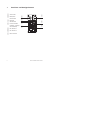 4
4
-
 5
5
-
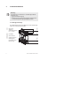 6
6
-
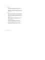 7
7
-
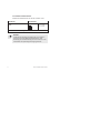 8
8
-
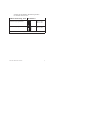 9
9
-
 10
10
-
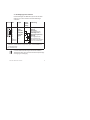 11
11
-
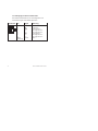 12
12
-
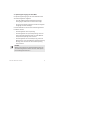 13
13
-
 14
14
-
 15
15
-
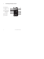 16
16
-
 17
17
-
 18
18
-
 19
19
-
 20
20
-
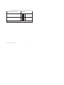 21
21
-
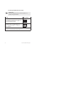 22
22
-
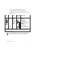 23
23
-
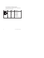 24
24
-
 25
25
-
 26
26
-
 27
27
-
 28
28
-
 29
29
-
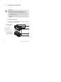 30
30
-
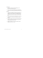 31
31
-
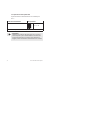 32
32
-
 33
33
-
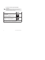 34
34
-
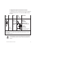 35
35
-
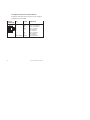 36
36
-
 37
37
-
 38
38
-
 39
39
-
 40
40
-
 41
41
-
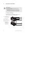 42
42
-
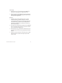 43
43
-
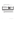 44
44
-
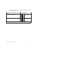 45
45
-
 46
46
-
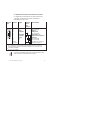 47
47
-
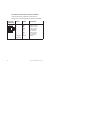 48
48
-
 49
49
-
 50
50
-
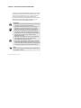 51
51
-
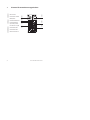 52
52
-
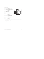 53
53
-
 54
54
-
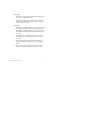 55
55
-
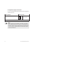 56
56
-
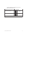 57
57
-
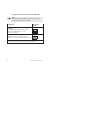 58
58
-
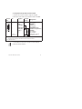 59
59
-
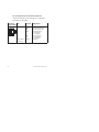 60
60
-
 61
61
-
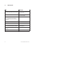 62
62
-
 63
63
-
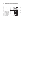 64
64
-
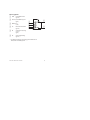 65
65
-
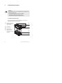 66
66
-
 67
67
-
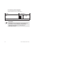 68
68
-
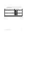 69
69
-
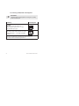 70
70
-
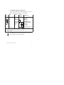 71
71
-
 72
72
-
 73
73
-
 74
74


Festo 555667 Brief description
- Tipo
- Brief description
- Este manual también es adecuado para
en otros idiomas
- français: Festo 555667
- italiano: Festo 555667
- English: Festo 555667
- Deutsch: Festo 555667
- svenska: Festo 555667
Artículos relacionados
Otros documentos
-
Baumer CPX Installation and Operating Instructions
-
Coleman 4D CPX 6 1000 LUMEN Manual de usuario
-
TSC CPX4 Series Product Sheet
-
Lifetime 90135 El manual del propietario
-
Lifetime 151110 El manual del propietario
-
-
-
Pepperl+Fuchs VAS/M-2A8L-KE4-6SE-EV Instrucciones de operación