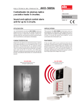
Alarma para cámara frigorífica con salida para 1 foco
Alarma óptica, acústica y alumbrado de socorro para cámaras frigoríficas a baja
temperatura o con atmósfera controlada. Compuestas de una fuente de alimentación
para ir montada en el exterior de la cámara y un foco con un pulsador para la petición de
socorro desde el interior.
El sistema incorpora 2 funciones de alarma, una que actúa con alimentación de red y otra
con sus acumuladores para garantizar el funcionamineto en caso de corte en el
suministro eléctrico.
Alimentación: AKO-52061 . . . . . . . . . . . . . . . . . . . . . . . . 230 V ~ ± 10%, 50/60 Hz
AKO-52066 . . . . . . . . . . . . . . . . . . . . 120 V ~ + 8% - 12%, 50/60 Hz
Potencia máxima absorbida: . . . . . . . . . . . . . . . . . . . . . . . . . . . . . . . . . . . . . . . 10 VA
Autonomía alumbrado + alarma:. . . . . . . . . . . . . . . . . . . . . . . . . . . . . . . . . . > 1 Hora
Acumuladores: . . . . . . . . . . . . . . . . . . . . . . . . . . . . . . . . . . . . . . . . . Ni-MH 700 mAh
Relé auxiliar: . . . . . . . . . . . . . . . . . . . . . . . . . . . . . . . . . . . . . . . . . . . . . 8 A, cos j =1
Temperatura ambiente de trabajo de la fuente de alimentación: . . . . . . . . . . 0 ºC a 50 ºC
Temperatura ambiente de trabajo del foco: . . . . . . . . . . . . . . . . . . . . . . . -50 ºC a 50 ºC
Temperatura ambiente de almacenaje de la fuente: . . . . . . . . . . . . . . . . . -30 ºC a 70 ºC
Temperatura ambiente de almacenaje del foco: . . . . . . . . . . . . . . . . . . . . -50 ºC a 70 ºC
Grado de protección: . . . . . . . . . . . . . . . . . . . . . . . . . . . . . . . . . . . . . . . . . . . . . IP 65
Categoría de instalación: . . . . . . . . . . . . . . . . . . . . . . . . . . . . . . . . . . II s/ EN 61010-1
Grado de polución:. . . . . . . . . . . . . . . . . . . . . . . . . . . . . . . . . . . . . . . II s/ EN 61010-1
Aislamiento doble entre alimentación, circuito secundario y salida relé.
Alarma para cámara frigorífica con salida de 1 foco:. . . . . . . . . . . AKO-52061 / 52066
Fuente de alimentación de repuesto: . . . . . . . . . . . . . . . . . . . AKO-520611 / 520661
Foco de repuesto con 2 m de cable: . . . . . . . . . . . . . . . . . . . . . . . . . . . . . AKO-52062
La alarma debe ser instalada en un sitio protegido de las vibraciones, del agua y de los gases
corrosivos, donde la temperatura ambiente no supere el valor reflejado en los datos técnicos.
Para que las alarmas tengan un grado de protección IP65, deberá instalarse correctamente
la junta entre el aparato y el perímetro del hueco del panel donde deba montarse.
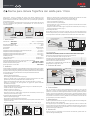
-Retirar la tapa T del equipo (Fig.1)
-Abrir el equipo y separar el frontal de la caja (Fig.2)
-Realizar los taladros para los prensaestopas necesarios para entrada de los cables
guiándose por los centros pretroquelados en los laterales de la caja.
-Realizar los 3 taladros para fijación de la caja en los centros indicados 1,2,3. (Fig.3)
-Realizar los 3 taladros en la pared siguiendo los agujeros de fijación realizados
previamente en el equipo.
-Fijar los prensaestopas en el equipo.
-Insertar y apretar los 3 tornillos+taco a través de la caja, en los 3 taladros de la pared.
-Insertar los cables en los prensaestopas.
-Montar el frontal en la caja (Fig.2).
-Insertar y apretar los tornillos D,F (Fig.1)
-Después de conectar los cables según el esquema de conexionado, cerrar la tapa T,
insertar y apretar los tornillos A,C (Fig.1)
-Retirar la tapa T del equipo (Fig.1)
-Abrir el equipo y separar el frontal de la caja (Fig.2)
-Reemplazar la junta instalada en el frontal por la junta para panelar teniendo en cuenta
su posición adecuada.
-Realizar un hueco en el panel de las dimensiones descritas (214 x 214 mm). (Fig.4)
1- Datos técnicos
2- Instalación
2.1 Montaje Mural
2.2 Montaje Panel (máximo grosor del panel: 3mm)
-Realizar los taladros para los prensaestopas necesarios para entrada de los cables
guiándose por los centros pretroquelados en los laterales de la caja.
-Acabar de taladrar los agujeros G, J con una broca de 4 mm.(Fig.3)
-Fijar los prensaestopas en el equipo.
-Insertar los cables en los prensaestopas.
-Juntar el frontal con la caja, a través del panel, y apretar los tornillos de 45 mm a través
de los taladros D,F,G, J (Fig.3)
-Después de conectar los cables según el esquema de conexionado, cerrar la tapa T,
insertar y apretar los tornillos A, C (Fig.1)
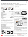
El foco debe instalarse en el interior de la cámara, junto a la puerta de salida para que
éste sea siempre visible y a una altura accesible para las personas. Se conecta de acuerdo
con el esquema de conexionado y respetando la situación de los colores de los cables.
CONECTAR LAS BATERIAS ANTES DE LA PUESTA EN MARCHA DEL EQUIPO.
Desconectar siempre la alimentación para realizar el conexionado.
El circuito de alimentación debe estar provisto de un
interruptor para su desconexión de mínimo 2 A situado
cerca del aparato. El cable de alimentación será del tipo
2 2
H05VV-F 2x0.5 mm o H05V-K 2x0.5 mm .
Los cables para el conexionado del contacto del relé,
2
deberán tener una sección de 2.5 mm .
Una vez conectada la alarma, estará permanentemente luciendo el foco. Caso de
producirse un corte en el suministro eléctrico, continuará luciendo el foco. Cuando una
persona en el interior de la cámara frigorífica desea dar la alarma, presiona el pulsador
del foco y se pone en funcionamiento la alarma acústica y luminosa del exterior. Ésta no
parará hasta que se restablezca la posición inicial del pulsador. El sistema funciona tanto
si hay tensión en la red como si no la hay, debido a sus acumuladores. El contacto del relé
auxiliar permite activar alarmas a distancia.
Limpie la superficie de la alarma con un paño suave, agua y jabón. No utilice detergentes
abrasivos, gasolina, alcohol o disolventes.
Este equipo incorpora acumuladores que deben reponerse cuando la autonomía del
equipo es inferior a la duración asignada en las especificaciones del mismo. Al final de la
vida del equipo, se deben llevar los acumuladores a un centro de recogida selectiva ó
bien devolver el equipo al fabricante.
Utilizar la alarma no respetando las instrucciones del fabricante, puede alterar los
requisitos de seguridad del aparato.
2.3 Montaje del Foco
2.4 Conexionado:
3- Funciones del frontal
4- Funcionamiento
5- Mantenimiento
6- Advertencias
E GB
5206H101 Ed.03
AKO-52061
AKO-52066
AKO-520611
AKO-520661
AKO-52062
FIG. 2
FIG. 1
222,1 mm
140 mm
222,1 mm
140 mm
FIG. 3
214 mm
214 mm
FIG. 4
HUECO
PANEL
Detalle taladros fijación
Taladros de fijación adecuados
para caja de empotrar universal
ALARMA VISUAL
ESTADO BATERÍA
ALARMA ACÚSTICA
FOCO CON
PULSADOR
ALARMA
PERSONA
ENCERRADA
Presionar ligeramente
para abrir la tapa
171
125,535
94
60
41,5
Max. Ø 3,7
LED Estado batería:
Rojo: Alimentación presente
y batería cargando.
Apagado: Alarma funcio-
nando con batería.
LEDs alarma activos:
Alarma visual y sonora
activa.
ALARM
ENTRADA FOCO
8 A
NO NCC
1 6
4
5
2 73 8
Alimentación
de red
+12 V 20 mA=
GND
Marrón
Negro
Azul

Nos reservamos el derecho de suministrar materiales que pudieran diferir levemente de los
descritos en nuestras Hojas Técnicas.Información actualizada en nuestra web: www.ako.com
We reserve the right to supply materials that might vary slightly to those described in our Technical
Sheets. Updated information is available on our website: www.ako.com
.
Av. Roquetes, 30-38 | 08812 Sant Pere de Ribes | Barcelona | España
Tel. (34) 938 142 700 | Fax (34) 938 934 054 | e-mail: [email protected] | www.ako.com
AKO ELECTROMECÀNICA, S.A.L.
355206101 REV.02 2012
Optical, acoustic alarm with lamp for cold room stores operating at low temperatures or
with controlled atmospheres. Comprised of a power source for mounting on the outside
of the cold room store and a lamp with a pushbutton for requesting help from inside.
Power supply: AKO-52061 . . . . . . . . . . . . . . . . . . . . . . . . 230 V ~ ± 10%, 50/60 Hz
AKO-52066 . . . . . . . . . . . . . . . . . . . . 120 V ~ + 8% - 12%, 50/60 Hz
Maximum input power: . . . . . . . . . . . . . . . . . . . . . . . . . . . . . . . . . . . . . . . . . . . 10 VA
Light + alarm autonomy time: . . . . . . . . . . . . . . . . . . . . . . . . . . . . . . . . . . . . > 1 Hour
Batteries: . . . . . . . . . . . . . . . . . . . . . . . . . . . . . . . . . . . . . . . . . . . . . Ni-MH 700 mAh
Auxiliary relay: . . . . . . . . . . . . . . . . . . . . . . . . . . . . . . . . . . . . . . . . . . . . 8 A, cos j =1
Power source working ambient temperature: . . . . . . . . . . . . . . . . . . . . . . 0 ºC to 50 ºC
Lamp working ambient temperature:. . . . . . . . . . . . . . . . . . . . . . . . . . . -50 ºC to 50 ºC
Power source storage ambient temperature: . . . . . . . . . . . . . . . . . . . . . -30 ºC to 70 ºC
Lamp storage ambient temperature: . . . . . . . . . . . . . . . . . . . . . . . . . . . -50 ºC to 70 ºC
Degree protection: . . . . . . . . . . . . . . . . . . . . . . . . . . . . . . . . . . . . . . . . . . . . . . . IP 65
Installation category: . . . . . . . . . . . . . . . . . . . . . . . . . . . . . . . . . . . . . II s/ EN 61010-1
Pollution degree: . . . . . . . . . . . . . . . . . . . . . . . . . . . . . . . . . . . . . . . . II s/ EN 61010-1
Double insulation between the power supply, the secondary circuit and the relay output.
cold room store alarm with 1 lamp:. . . . . . . . . . . . . . . . . . . . . . . AKO-52061 / 52066
Spare power source: . . . . . . . . . . . . . . . . . . . . . . . . . . . . . . . AKO-520611 / 520661
Spare spotlight with 2 m of cable: . . . . . . . . . . . . . . . . . . . . . . . . . . . . . . AKO-52062
The alarm should be installed in a place protected from vibrations, water and corrosive gases,
and where ambient temperature does not surpass the value specified in the technical data.
In order for the alarms to have IP65 protection, the gasket should be properly installed
between the apparatus and the perimeter of the panel cut-out where it is to be fitted.
-Remove cover T from the equipment (Fig.1).
-Open the equipment and separate the front part of the housing (Fig.2).
-Drill the holes for the glands that are necessary for the cables to pass through, guided by
the pre-cut centres on the sides of the housing.
-Drill 3 holes for anchoring the housing at the centres indicated 1, 2, 3 (Fig.3).
-Drill 3 holes in the wall, in accordance with the anchoring holes made previously in the
equipment.
-Anchor the glands to the equipment.
-Insert and tighten the 3 screws+plug through the housing, on the 3 holes drilled in the wall.
-Insert the cables into the glands.
-Mount the front part on the housing (Fig.2).
-Insert and tighten screws D, F (Fig.1)
-After connecting the cables based on the connection diagram, close cover T, insert
and tighten screws A, C (Fig.1).
-Remove cover T from the equipment (Fig.1).
-Open the equipment and separate the front part of the housing (Fig.2).
-Replace the joint installed at the front by the panelling joint, ensuring that it is in the
right position.
The system has 2 alarm functions, one for operation with electrical power supply and
other one to operatre with its batteries in case of electrical power cuts.
1- Technical data
2- Installation
2.1 Wall mounting
2.2 Panel Mounting (maximum panel thickness: 3mm)
-Make an opening in the panel with the dimensions indicated (214 x 214 mm) (Fig.4).
-Drill the holes for the glands that are necessary for the cables to pass through, guided
by the pre-cut centres on the sides of the housing.
-Finish drilling holes G, J with a 4 mm bit(Fig.3).
-Anchor the glands to the equipment.
-Insert the cables into the glands.
-Join the front with the housing, through the panel and tighten the 45 mm screws
through holes D, F, G, J (Fig.3).
-After connecting the cables in accordance with the connection diagram, close cover T,
and insert and tighten screws A, C (Fig.1).
The lamp must be installed inside the cold room store, next to the door so that it is always
visible and can easily be reached by any person. Connect the equipment in accordance
with the connection diagram, respecting the position of the cable colours.
CONNECT THE BATTERIES PRIOR TO STARTING UP THE EQUIPMENT.
Always disconnect the power supply when making the connections.
The power supply circuit should be connected with a
minimum 2 A, switch located close to the unit. Power
2
supply cables should be H05VV-F 2x0,5 mm or
2
H05V-K 2x0,5 mm .
Section of connecting wires for relays contacts should
2
be 2,5 mm .
After connecting the alarm, the lamp will be lit permanently. If there is a power failure,
the lamp will continue to be lit. In the event that anyone inside the cold room store
wishes to raise the alarm, press the lamp pushbutton and the acoustic and visual alarm
on the outside of the cold room store will be set in operation. It will not stop until the
pushbutton is returned to its initial position. The system will operate with and without
electricity, due to the energy accumulated by the battery. Contact of the auxiliary relay
enables the alarms to be activated from a distance.
Clean the alarm surface with a soft cloth, soap and water. Do not use abrasive
detergents, petrol, alcohol or solvents.
This unit includes batteries which must be replaced when the device's autonomy time is
below the indicated in the specifications. At the end of the unit's service life. the batteries
should be disposed of at a selective refuse collection site or return to the manufacturer.
The use of the unit without observing the manufacturer's instructions may alter its safety
qualification.
2.3 Lamp Mounting
2.4 Wiring:
3- Front panel functions
4- Operation
5- Maintenance
6- Warnings
AKO-52061
AKO-52066
AKO-520611
AKO-520661
AKO-52062
FIG. 2
FIG. 1
222,1 mm
140 mm
222,1 mm
140 mm
FIG. 3
214 mm
214 mm
FIG. 4
PANEL
CUT-OUT
View of holes drilled
for anchoring.
Anchoring holes that are suitable for use
in housings with universal embedding.
VISUAL ALARM
BATTERY STATUS
ACOUSTIC ALARM
LAMP WITH
PUSHBUTTON
PERSON
TRAPPED
ALARM
Press lightly to open the cover.
171
125,535
94
60
41,5
Max. Ø 3,7
Battery status LED:
Red: power supply.
OFF: Alarm working with
batteries.
Alarm LEDs connected:
Visual and acoustic alarm
ON.
ALARM
LAMP INPUT
8 A
NO NCC
1 6
4
5
2 73 8
Power
supply
+12 V 20 mA=
GND
Brown
Black
Blue
Cold room store alarm with output for 1 lamp
-
 1
1
-
 2
2


AKO 230 V Cold room store alarm Manual de usuario
- Tipo
- Manual de usuario
- Este manual también es adecuado para
en otros idiomas
Artículos relacionados
-
AKO 59830 Instrucciones de operación
-
AKO AKO-59830 Manual de usuario
-
AKO 52062 Manual de usuario
-
AKO AKO-52214 Manual de usuario
-
AKO AKO-55424 Trapped person alarm Guía de inicio rápido
-
AKO AKO-55624 / 55724 Gas Leak Detection Alarm Manual de usuario
-
-
-
-