Truper COMP-60LB-D El manual del propietario
- Categoría
- Compresores de aire
- Tipo
- El manual del propietario

Modelo: COMP-60LB-D
Código: 19391
NOTA IMPORTANTE: Este producto no debe
quedar expuesto a goteo o salpicaduras por líquidos.
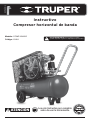
Compresor horizontal de banda
Instructivo
Lea este Instructivo por completo
antes de usar la herramienta.
ATENCIÓN
ESPAÑOL
ENGLISH

1
CONSERVE ESTE INSTRUCTIVO
Usted necesitará el instructivo para consultar las reglas de
seguridad y precaución, instrucciones de ensamble,
procedimientos de mantenimiento y operación.
Mantenga su factura junto con este instructivo. Escriba el número
de factura en la parte interna de la cubierta frontal. Guarde el
instructivo y la factura en un lugar seco y seguro para futuras
referencias.
INSTRUCCIONES DE SEGURIDAD
AVISO: Cuando utilice su herramienta, siempre deben
seguirse algunas precauciones básicas de seguridad
para reducir riesgos de daños personales y daños al
equipo.
Lea todas las instrucciones antes de usar su herramienta.
1. Mantenga el área de trabajo en orden. Las áreas y bancos
desordenados propician accidentes.
2. Observe las condiciones del área de trabajo. No
utilice máquinas o herramientas eléctricas en áreas
mojadas o húmedas. No exponga su herramienta a la
lluvia. Mantenga el área de trabajo bien iluminada. No
utilice herramientas eléctricas en presencia de gases o
líquidos inflamables.
3. Prevéngase contra los choques eléctricos. Prevenga
el contacto del cuerpo con superficies conectadas a
tierra tales como tuberías, radiadores, y refrigeradores.
4. Mantenga a los niños alejados Los niños nunca
deben estar cerca del área de trabajo. No permita que
ellos sostengan máquinas, herramientas o cables de
extensión. No permita que otras personas toquen la
herramienta, manténgalas alejadas de su campo de
trabajo.
5. Mantenga guardado el equipo mientras no esté
en uso. Cuando no esté en uso, la herramienta debe
guardarse en un lugar seco y libre de polvo. Siempre guarde
su herramienta bajo llave para que no esté al alcance de los
niños.
6. No fuerce la herramienta. Esta hará mejor su trabajo y será
más segura dentro del rango para la cual fue diseñada. No
utilice aditamentos inapropiados para intentar exceder la
capacidad de la herramienta.
7. Utilice la herramienta eléctrica adecuada. No utilice
herramientas demasiado débiles para ejecutar trabajos
pesados. No utilice herramientas eléctricas para trabajos
pesados para los cuales no ha sido diseñada.
8. Utilice la indumentaria apropiada. No utilice ropa suelta,
guantes, corbatas o joyería que pueda ser atrapada en las
partes móviles. No utilice calzado resbaloso. Utilice algún
protector de cabello para retener el cabello largo.
9. Utilice protección para ojos. Siempre utilice
accesorios de seguridad aprobados por la Norma
Oficial Mexicana (NOM), como es el caso de goggles,
caretas y mascarillas contra polvo, cuando trabaje
con materiales que despidan partes metálicas, virutas
o polvos químicos.
10. No use el cable de alimentación para nes para los cuales
no está dispuesto. No lleve la herramienta colgada del cable
y no tire de éste para desconectar la clavija de la base de
enchufe. Proteja el cable contra el calor, el aceite y las
esquinas afiladas.
11. Aance la pieza de trabajo. Utilice un dispositivo de fijación
o una mordaza para mantener firme la pieza de trabajo. Esto
es más seguro que usando una sola mano y le permite tener
ambas manos libres. Mantenga el balance adecuado todo el
tiempo sobre sus pies. No trate de alcanzar algo sobre la
máquina o se cruce cuando esté en funcionamiento.
12. No extienda su radio de acción. Evite toda postura que
cause cansancio. Cuide de que su posición sea segura y de
que conserve el equilibrio.
13. Mantenga las herramientas en las mejores condiciones.
Mantenga las herramientas limpias para tener la mejor
ejecución y seguridad. Siga las instrucciones para la
lubricación y cambio de accesorios. Verifique los cables de
la herramienta periódicamente y si se encuentran dañados,
llévelos a reparar a un Centro de Servicio Autorizado Truper®.
Los mangos o manijas deben siempre permanecer limpios,
secos y libres de aceite y grasas.
14. Desconecte la herramienta. Desconecte la
herramienta cuando no esté en uso, antes de proceder
al mantenimiento.
15. Reduzca el riesgo de arranques accidentales. No
lleve ninguna herramienta con el dedo puesto sobre el
interruptor mientras esté conectado a la red eléctrica.
Asegúrese de que el interruptor esté en la posición
“apagado” (OFF) antes de conectar el cable de
alimentación.
16. Extensiones para exterior. En el exterior, utilice solamente
cables de extensión homologados y convenientemente
marcados.
17. Manténgase alerta. Fíjese en lo que está haciendo, utilice
su sentido común. No opere ninguna herramienta cuando
esté cansado.
18. Revise las partes dañadas. Antes de continuar utilizando
la máquina, los protectores u otras partes móviles que
pudieran estar dañadas deben ser cuidadosamente revisadas,
para asegurarse que operan apropiadamente y trabajarán
como debe ser. Verifique también la alineación de las partes
móviles, si están atascadas, o si hay alguna probable ruptura
de las partes, verifique también el montaje, así como cualquier
otra condición que pueda afectar la operación de la
herramienta. Todos los componentes deben estar montados
adecuadamente y cumplir los requisitos para garantizar el
correcto funcionamiento del aparato. Un protector u otra
parte que estén dañadas deberán ser apropiadamente
reparadas o cambiadas. Todo interruptor de mando
deteriorado, deberá ser reemplazado por un Centro de Servicio
Autorizado Truper®. No utilice ninguna herramienta eléctrica
en la cual el interruptor no tenga contacto.
19. Reemplazo de partes y accesorios. Cuando necesite
remplazar las piezas, utilice solamente refacciones originales
Truper®, destinados para usarse con está herramienta.
20. Para su seguridad personal utilice
únicamente los accesorios o aparatos adicionales
indicados en las instrucciones de manejo o
recomendados por el fabricante de la herramienta. La
utilización de accesorios diferentes a los indicados en
las instrucciones de manejo, puede ocasionar riesgo
personal.
21. Protección para oídos. Utilice protectores
auriculares, cuando ejecute servicios que hagan ruidos
superiores a 85 dB
El aparato no está previsto para su utilización por personas
(incluidos los niños) cuyas capacidades físicas, sensoriales o
mentales son reducidas, o por personas sin experiencia o
conocimientos, salvo si éstas se encuentran vigiladas por una
persona responsable de su seguridad o han recibido
instrucciones previas sobre el uso del aparato.
Los niños deberán estar bajo supervisión para
cerciorarse de que no jueguen con el aparato.
Se requiere estricta supervisión cuando las personas
discapacitadas o los niños utilicen cualquier aparato
eléctrico o estén cerca de él.
ATENCIÓN
AVISO
ATENCIÓN

CARACTERÍSTICAS TÉCNICAS:
Tensión: 120 V~ / 220 V~
Frecuencia: 60 Hz
Corriente: 20 A / 10 A
Velocidad: 3 450 r/min
Potencia nominal
del motor: 2 250 W
Potencia máxima: 3 000 W
Máxima presión: 800 kPa (116 PSI)
Capacidad de tanque: 60 L
Grado IP: IP20
Flujo de aire: 241 L/min (8,5 CFM) - 276 kPa (40 PSI)
212 L /min (7,5 CFM) - 620 kPa (90 PSI)
El cable de alimentación tiene sujeta-cables tipo: Y
Todos los conductores son: 14 AWG x 3C con temperatura de
aislamiento de 105 ˚C
La clase de construcción de la herramienta es: Aislamiento
básico.
Clase de aislamiento: Clase l
La clase de aislamiento térmico de los devanados del motor:
Clase B
Si el cable de alimentación se daña, éste debe ser
reemplazado por el fabricante o Centro de Servicio Autorizado
Truper
®
, con el fin de evitar algún riesgo de descarga o accidente
considerable.
El tipo de sujeta-cables empleado para este producto es tipo “Y”.
La construcción de este producto esta diseñada de manera que
su aislamiento eléctrico es alterado por salpicaduras o
derramamiento de líquidos durante su operación.
Antes de obtener acceso a las
terminales, todos los circuitos de alimentación deben
ser desconectados.
No se recomienda el uso de extensiones
eléctricas en los compresores, su uso provocaría una
caída de tensión ocasionando pérdida de potencia y
sobrecalentamiento del motor. Aumente el alcance de acción del
compresor conectándole una manguera de mayor longitud a la
salida.
LINEAMIENTOS ESPECIFICOS DE SEGURIDAD.
• No use aire comprimido para limpiarse la ropa.
• No aplique aire comprimido directamente a la piel.
• No aplique aire comprimido para propósitos de respiración o
para cargar cilindros de aire para respiradores, a menos que
el aire se haya filtrado usando filtros diseñados específicamente
para este propósito.
• No use una tubería de aire abierta, podría “chicotear” y
ocasionar lesiones.
• No use líquidos inflamables para limpiar el compresor.
• No use flama abierta para inspeccionar el interior del compresor
o el depósito de presión.
• Use protección de ojos cuando use aire comprimido para
limpiar el equipo.
• Tome precauciones para asegurar que no se soplen partículas
hacia otras personas: siempre use una pistola de aire para la
limpieza.
• Asegure que todo el equipo auxiliar esté en buen estado de
funcionamiento, y que tenga la capacidad correcta para esta
aplicación.
• Revise regularmente que todas las cubiertas estén fijas y
firmemente colocadas.
• Reemplace todas las partes, herramientas y accesorios si son
inadecuados para una operación segura.
• Instale una válvula sin retorno o de corte en la tubería de
entrega si el compresor se acoplará en paralelo con otro
compresor, o si se conectará a un sistema de suministro de
aire.
• Asegure que toda la tubería y mangueras conectadas al
compresor tengan el diámetro correcto y una resistencia
adecuada para la presión máxima que provee el compresor.
• Instale el compresor de manera que se tenga disponible un
suministro adecuado de aire de ventilación hacia el compresor,
y que los conductos de aire a través de las admisiones de la
cubierta y del ventilador del motor no estén restringidos.
REVISE:
La dirección de rotación de la banda durante el arranque inicial,
y después de cualquier modificación en los componentes eléctricos
o conexiones.
Apague el compresor y desconéctelo del tomacorriente, ventile
completamente antes de desensamblar cualquier componente o
de realizar cualquier trabajo de mantenimiento.
COMPRESORES DE TRANSMISIÓN POR BANDA
Los compresores de aire de transmisión por banda se entregan
instalados en ruedas. El modelo instalado en ruedas absorbe la
vibración, pero debe colocarse en un piso firme y nivelado.
INSTALACIÓN Y VENTILACIÓN
Debe permitirse un acceso y espacio adecuado en la parte superior
y alrededor del compresor para darle servicio. Debe proporcionarse
una protección adecuada contra el clima. Es esencial que se tenga
buena ventilación. Para una eficiencia máxima, el aire de admisión
debe estar tan frío y limpio como sea posible (una disminución
de temperatura de 3 °C aumentará el volumen de aire entregado
en 1%). Las impurezas gaseosas y partículas, el polvo abrasivo
y los gases corrosivos son especialmente dañinos. Los vapores
del escape representan un peligro si el aire comprimido se utiliza
para el suministro de aparatos de respiración.
Instale el compresor lo más alejado posible del área de trabajo
para evitar que sean succionadas las partículas generadas por el
trabajo realizado (pintura, polvo, etc.)
CONEXIÓN AL SUMINISTRO DE ENERGÍA PRINCIPAL
El compresor debe instalarse tan cerca como sea posible del
suministro de energía principal. Coloque el selector de tensión
en la posición correcta de acuerdo a la tensión a la que va a
conectar el compresor (120 V~ o 220 V~)
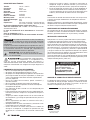
Este aparato debe conectarse a tierra.
ATENCIÓN
2
ADVERTENCIA
ADVERTENCIA
ADVERTENCIA
ADVERTENCIA
Este equipo DEBE SER UTILIZADO
con una alimentación de
120 V~ / 220 V~, utilizar una
TENSIÓN DIFERENTE DAÑA
SEVERAMENTE el producto.
TIERRA
CORRIENTE
Esta herramienta cumple
con la Norma Oficial
Mexicana (NOM).

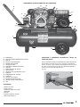
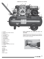
A
A) MANUBRIO
B) CAJA DE INTERCONEXIÓN DEL MOTOR
C) MOTOR
D) VÁLVULA ANTIRETORNO
E) BANDA CON GUARDA
F) FILTRO DE AIRE
G) TAPÓN DE LLENADO DE ACEITE
H) CÁRTER
I) MIRILLA NIVEL DE ACEITE
J) PRESOSTATO
K) VÁLVULAS DE SALIDA DE 6,5 mm
L) TANQUE
M) MANÓMETRO DE TANQUE
N) LLANTAS
O) VÁLVULA DE PURGA
P) BOTÓN DE INTERRUPTOR
Q) PROTECTOR DE SOBRECARGA
R) ASA
ACCESORIOS:
1 Botella de aceite
2 Filtros de aire
1 Tapón del depósito de aceite
1 Manubrio
2 Ruedas
2 Soportes frontales de hule
1 Bolsa con tornillería
OPERACIÓN Y ARRANQUE AUTOMÁTICO. ANTES DE
CONECTAR REVISE:
Que el selector de tensión esté colocado en la posición correcta
de acuerdo a la tensión a la que va a conectar el compresor
(120 V~ o 220 V~) Que la lectura del manómetro de aire sea de
cero. Que el nivel de aceite en el cárter de la bomba del compresor
esté en la marca del indicador de nivel.
(Fig. A)
3
DIAGRAMA DE LA UNIDAD COMPLETA DEL COMPRESOR
R
B
Q
C
D
E
F G
H
J
K
L
M
I
P
N
O
A

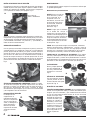
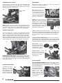
BOTÓN DE INTERRUPTOR DE PRESIÓN:
El compresor cuenta con un interruptor de presión que combina
el botón de paro / arranque en la parte superior. El botón se debe
colocar en la posición de "ARRIBA" para arrancar el compresor
y en la posición de "Abajo" para apagarlo. Fig. B
Antes de arrancar el compresor, debe descargarse cualquier aire
comprimido que haya permanecido arriba del pistón y en el tubo
de alimentación, presionando el botón del interruptor de presión,
y levantándolo nuevamente a la posición “|” (encendido). El
motor arrancará inmediatamente.
OPERACIÓN AUTOMÁTICA
Una vez que haya arrancado, el compresor se parará y arrancará
automáticamente. Su compresor cuenta con un interruptor de
presión preajustado de fábrica para parar el motor cuando la
presión del tanque alcanza su presión máxima de operación, y
para arrancar el motor otra vez automáticamente cuando la
presión del tanque disminuye a la presión preajustada. En caso
de ser necesario parar el compresor antes de que se alcance la
presión normal de corte, debe presionarse el botón del interruptor.
Fig. C
VÁLVULA DE DESCARGA DEL COMPRESOR: El botón en la parte
de arriba del interruptor de presión negro activa una válvula
pequeña sin retorno, que desfoga el aire de arriba del pistón y
del tubo de alimentación del tanque. Presione el botón
ocasionalmente para asegurar que la válvula está funcionando
y descargando el aire correctamente.
REGULACIÓN DE PRESIÓN
El compresor esta
equipado con un
regulador de presión
de aire el cual permite
ajustar la presión de
salida, se debe girar la
perilla frontal para
obtener la presión
requerida de acuerdo
al trabajo a realizar.
Fig. D
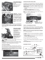
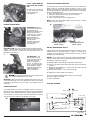
MANTENIMIENTO
Un mantenimiento regular asegurará una eficiencia máxima por
un período prolongado.
Mantenimiento preventivo diario
ACEITE: Revise el nivel del
aceite del cárter y rellene
de ser necesario. Si su
compresor no se usa
diariamente, revise el nivel
de aceite del cárter antes
de arrancarlo. Cambie el
aceite después de
500 horas. Fig. E
AGUA: El agua que se almacena
en el fondo del tanque al
condensarse el aire, debe drenarse
usando la válvula de purga que se
localiza en la parte inferior del
tanque del compresor, desatornille
el anillo moleteado para drenar y
vuelva a apretar antes de encender
el compresor. Fig. F
FUGAS: Revise para detectar fugas en el compresor, conexiones,
tuberías de alimentación y acoplamientos, y vuelva a sellar de
ser necesario. Recuerde que aún una fuga pequeña puede
ocasionar que se desperdicie el aire comprimido, lo que le costará
la energía extra utilizada y reducirá la vida del compresor.
TORNILLOS DE LA CABEZA DE CILINDROS: Estos deben
revisarse y deben apretarse después del primer día de operación,
después de 50 horas, y cada 4 meses posteriormente. La cabeza
de cilindros debe estar completamente fría antes de realizar esta
operación. El valor del torque es de 23 Nm (16,96 Lb-pie).
FILTRO DE AIRE:
Revise y limpie soplando
con aire comprimido. Si
está muy contaminado,
reemplace el cartucho.
Fig. G
VÁLVULA DE SEGURIDAD:
Esta ajustada para activarse
y liberar presión de aire en
caso de falla del interruptor
de presión. Fig. H
DESPUÉS DE 200 HORAS
TENSIÓN Y ALINEACIÓN DE LA BANDA: Con la energía principal
aislada, revise la polea del motor y el volante de la bomba, para
asegurar que están alineados, y que el movimiento en la banda
en V en el punto medio no debe exceder de 12 mm. Al mismo
tiempo, revise que estén
apretados los tornillos de
sujeción del motor y los
tornillos de sujeción de
la bomba, y revise si hay
desgaste en la banda.
También verifique que el
volante de la bomba y
que la polea del motor
estén asegurados en sus
flechas respectivas.
Fig. I
E
F
CG
H
D
4
I
B
Interruptor de
PARO / ARRANQUE
AVISO

CADA CUATRO MESES O
DESPUÉS DE 500 HORAS
DE USO
ACEITE: Drene el aceite y
rellene hasta el nivel
correcto con aceite
SAE-30. Fig. J
MANTENIMIENTO GENERAL
LIMPIEZA: Mantenga
limpio el interior y exterior
del compresor. Cambie el
aceite regularmente, y
mantenga limpias todas
las superficies externas.
Un interior limpio asegura
una buena eficiencia
mecánica, y un exterior
limpio permite una
disipación más eficiente
del calor al aire circulante.
Fig. K
ACCIÓN DE SUCCIÓN: Coloque suavemente su mano sobre los
orificios de admisión del filtro, y se escuchará claramente la
succión de aire. Una succión deficiente sugiere que el filtro de
aire está bloqueado, o que están dañadas las válvulas de
admisión. Fig. L
ANILLOS DEL PISTÓN:
Los anillos de sellado y
los anillos del raspador
de aceite deben
inspeccionarse cuando el
compresor está
consumiendo aceite
excesivamente, lo que
indica que los anillos
están desgastados y
deben reemplazarse.
Siempre debe cambiarse
el aceite cuando se
reemplazan los anillos u
otros componentes
mayores.
Este tipo de ajustes se deben realizar en un
Centro de Servicio Autorizado Truper.
RODAMIENTOS: Al revisar o cambiar los anillos del pistón, deben
verificarse los rodamientos del cigüeñal para determinar si están
desgastados, y deben reemplazarse de ser necesario.
SELECTOR DE TENSIÓN
Este compresor puede trabajar a 2 tensiones (120 V~ ó 220 V~);
por lo cual cuenta con un selector de tensión ubicado en la caja
de interconexión del motor. Dependiendo de la tensión de
alimentación a la cual se haya conectado, es que se tiene que
mover el selector para una correcta puesta en marcha y trabajo
futuro del compresor. Fig. M
PROTECCIÓN CONTRA SOBRE CARGA
El compresor cuenta con protectores térmicos Fig. N (botón de
color rojo para alimentación a 220 V~ y botón de color negro
para alimentación a 120 V~) que evitan que el motor sufra un
calentamiento excesivo. El motor se apaga cuando se activa el
protector térmico en función, para restablecer el motor siga los
siguientes pasos:
1.- Presione el interruptor para asegurar que el compresor esta
apagado.
2.- Deje enfriar el compresor al menos 5 minutos.
3.- Oprima el interruptor térmico
4.- Levante el interruptor para encender el compresor.
NOTA: Si la unidad se apaga de nuevo, por favor acuda a un
Centro de Servicio Autorizado Truper.
POLEA DE TRANSMISIÓN DEL MOTOR
Después de aislar la electricidad, y de retirar la guarda y la banda,
la polea puede retirarse usando un extractor conocido como
“Ouller”. No golpee la polea con un martillo para retirarla de la
flecha, ya que esto dañará los rodamientos del motor.
MOTOR: Si el motor no arranca o se para durante la operación,
esto no significa necesariamente que el motor está mal. Un motor
que “zumba” puede indicar:
a) Caída de tensión en la línea de alimentación o conexiones
sueltas
b) Fugas en la válvula sin retorno, lo que ocasiona contrapresión
desde el receptor.
c) Se está usando el procedimiento de arranque incorrecto (ver
arranque y operación automática).
d) Cárter agarrotado debido a falta de aceite.
Un motor aparentemente muerto puede indicar:
a) Que se activó el dispositivo de protección de sobrecarga
térmica.
b) Que se fundieron los fusibles del suministro de energía.
c) Una conexión suelta.
DIAGRAMA ELÉCTRICO
K
5
J
L
AVISO
Cable café Cable azul
Interruptor de palanca
Cable rojo
B2 B4
A1 A3 A5
B6
Sobrecarga
Interruptor amarillo
Cable gris
Sobrecarga
Cable naranja
Cable blanco
Interruptor
cable negro
M
N
Protector térmico para
alimentación 220 V~ Protector térmico para
alimentación a 120 V~

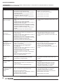
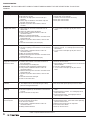
SOLUCIÓN DE PROBLEMAS
POR SU PROPIA SEGURIDAD, SIEMPRE APAGUE Y DESCONECTE LA MAQUINA ANTES DE INTENTAR
SOLUCIONAR CUALQUIER PROBLEMA.
CAUSAS
1. Filtro de admisión tapado.
2. Viscosidad del aceite demasiado baja.
3. Nivel de aceite demasiado alto (cuando es posible
un llenado excesivo).
4. Anillos del pistón roto o no asentados, claros no
escalonados. Atorados en la ranura.
5. Cilindros o pistones con rasguños, desgastados o
rayados.
1. Polea suelta, o juego axial excesivo en la flecha del
motor.
2. Carbón en la parte superior del pistón.
3. Válvulas con fugas, rotas, carbonizadas o sueltas, o
conductos de aire restringidos.
4. Rodamientos de las bielas desgastados o rayados.
5. Rodamiento defectuoso en el cigüeñal o en la flecha
del motor. Ventilador del motor suelto.
6. Cilindros o pistones con rasguños, desgastados o
rayados.
7. Banda de transmisión con demasiada holgura.
1. Filtro de admisión tapado.
2. Fugas de aire en la tubería (en la máquina o en el
sistema externo).
3. Válvulas con fugas, rotas, carbonizadas o sueltas, o
conductos de aire restringidos.
4. Rodamientos de las bielas desgastados o rayados.
5. Rodamiento defectuoso en el cigüeñal o en la flecha
del motor. Ventilador del motor suelto.
6. Banda de transmisión con demasiada holgura.
1. Viscosidad del aceite demasiado alta.
2. Puede haber un falso contacto de las terminales del
motor o sus conexiones.
3. Caída de tensión en la línea de alimentación.
4. Regulación deficiente de la energía (línea
desequilibrada).
5. Válvulas con fugas, rotas, carbonizadas o sueltas, o
conductos de aire restringidos.
6. Rodamiento defectuoso en el cigüeñal o en la flecha
del motor. Ventilador del motor suelto.
7. Cilindros o pistones con rasguños, desgastados o
rayados.
8. Banda de transmisión demasiado apretada.
9. Fallas en la válvula antiretorno.
1. Se esta usando un aceite incorrecto.
2. El compresor ha operado durante un periodo
considerable en un lugar húmedo.
1. Es necesario drenar el tanque.
2. Fugas de aire en la tubería (en la máquina o en el
sistema externo).
3. Fugas en la válvula de seguridad del tanque.
1. Es posible que el volante se encuentre bloqueado.
2. Fugas en la válvula de seguridad del tanque.
3. Nivel de aceite demasiado bajo.
4. Válvulas con fugas, rotas , carbonizadas o sueltas, o
conductos de aire restringidos.
5. Dirección de rotación incorrecta.
SOLUCIONES
1. Limpie el filtro o reemplácelo si es necesario.
2. Cambie y use el aceite correcto.
3. Retire el exceso de aceite en el cárter.
4. Acuda al CSAT* más cercano.
5. Acuda al CSAT* más cercano.
1 - 7. Para servicio y reparación, acuda al CSAT* más
cercano.
1. Limpie el filtro o reemplácelo si es necesario.
2. Revise para detectar fugas de aire. Use cinta
selladora en todas las conexiones con fugas.
3 - 6. Para servicio y reparación, acuda al CSAT* más
cercano.
1. Cambie y use el aceite correcto.
2. Acuda al CSAT* más cercano.
3. Revise la tensión de la línea de alimentación, los
fusibles o corrija la sobrecarga del motor.
4. Consulte a un electricista calificado.
5 - 9. Para servicio y reparación, acuda al CSAT* más
cercano.
1. Cambie y use el aceite correcto.
2. Para servicio y reparación, acuda al CSAT* más
cercano.
1. Abra la válvula ubicada en la parte inferior del tanque
para drenar.
2. Revise para detectar fugas de aire. Use cinta
selladora en todas las conexiones con fugas.
3. Revise para detectar fugas , si es necesario
reemplazar la válvula acuda a un CSAT*.
1. Acuda al CSAT* más cercano.
2. Revise para detectar fugas , si es necesario
reemplazar la válvula acuda a un CSAT*.
3. Agregue aceite al cárter hasta el nivel correcto.
4. Acuda al CSAT* más cercano.
5. Acuda al CSAT* más cercano.
PROBLEMA
Bombeo de aceite
Golpes o traqueteo
Disminuye la
alimentación de aire
Se dispara la
sobrecarga del motor
o consume una
corriente excesiva
Oxidación en los
cilindros
Arranques y paros
excesivos
El compresor funciona
excesivamente
caliente
*CSAT: Centro de Servicio Autorizado Truper®
6
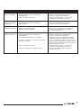
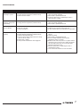
ADVERTENCIA

CAUSAS
1. Caída de tensión en la línea de alimentación.
2. Regulación deficiente de la energía (línea
desequilibrada).
3. Fallas en la válvula antiretorno.
1. Caída de tensión en la línea de alimentación.
2. Regulación deficiente de la energía (línea
desequilibrada).
1. Viscosidad del aceite demasiado baja.
2. Nivel de aceite demasiado bajo.
3. Atmósfera demasiado polvosa.
1. Caída de tensión en la línea de alimentación.
2. Regulación deficiente de la energía (línea
desequilibrada).
3. El capacitor presenta fallas o se ha dañado.
4. La presión en el tanque es mayor que la presión de
corte del interruptor.
5. Fallas en la válvula antiretorno.
6. Revise si se disparó la sobrecarga del motor.
SOLUCIONES
1. Revise la tensión de la línea de alimentación, los
fusibles o corrija la sobrecarga del motor.
2. Consulte a un electricista calificado.
3. Revise para detectar fugas , si es necesario
reemplazar la válvula acuda a un CSAT*.
1. Revise la tensión de la línea de alimentación, los
fusibles o corrija la sobrecarga del motor.
2. Consulte a un electricista calificado.
1. Cambie y use el aceite correcto.
2. Agregue aceite al cárter hasta el nivel correcto.
3. Se necesita dar mantenimiento con mayor
frecuencia al filtro de aire.
1. Revise la tensión de la línea de alimentación, los
fusibles o corrija la sobrecarga del motor.
2. Consulte a un electricista calificado.
3. Haga que se revisen los capacitores del motor
(unidades monofásicas solamente) en un CSAT*.
4. Revise si la presión del tanque es más alta que la
presión de corte del interruptor de presión (el motor
volverá a arrancar cuando la presión del tanque cae
abajo de la presión de corte).
5. Revise para detectar fugas , si es necesario
reemplazar la válvula acuda a un CSAT*.
6. Presione el botón del térmico para volver a
reestablecer el motor.
PROBLEMA
El compresor no
alcanza su velocidad
Parpadean las luces
cuando está operando
el compresor
Pistón anormal, anillo
o cilindro desgastados
El motor no funciona
7

CENTROS DE SERVICIO AUTORIZADOS TRUPER®
Venta de partes, componentes, consumibles y accesorios.
AGUASCALIENTES | DE TODO PARA LA CONSTRUCCIÓN
GRAL. BARRAGÁN #1201, COL. GREMIAL, C.P. 20030,
AGUASCALIENTES, AGS. TEL.: 01 (449) 994 0537
BAJA CALIFORNIA | SUCURSAL TIJUANA
AV. LA ENCANTADA, LOTE #5, PARQUE INDUSTRIAL EL FLORIDO II,
C.P 22244, TIJUANA, B.C. TEL.: 01 (664) 969 5100
BAJA CALIFORNIA SUR | FIX FERRETERÍAS
FELIPE ÁNGELES ESQ. RUIZ CORTÍNEZ S/N, COL. PUEBLO NUEVO,
C.P. 23670, CD. CONSTITUCIÓN, B.C.S. TEL.: 01 (613) 132 1115
CAMPECHE | TORNILLERÍA Y FERRETERÍA AAA
AV. ÁLVARO OBREGÓN #324, COL. ESPERANZA C.P. 24080
CAMPECHE, CAMP. TEL.: 01 (981) 815 2808
CHIAPAS | FIX FERRETERÍAS
AV. CENTRAL SUR #27, COL. CENTRO, C.P. 30700, TAPACHULA,
CHIS. TEL.: 01 (962) 118 4083
CHIHUAHUA | SUCURSAL CHIHUAHUA
AV. SILVESTRE TERRAZAS #128-11, PARQUE INDUSTRIAL BAFAR,
CARRETERA MÉXICO CUAUHTÉMOC, C.P. 31415, CHIHUAHUA, CHIH.
TEL. 01 (614) 434 0052
CIUDAD DE MÉXICO | FIX FERRETERÍAS
EL MONSTRUO DE CORREGIDORA, CORREGIDORA # 22,
COL. CENTRO, C.P. 06060, CUAUHTÉMOC, CDMX.
TEL: 01 (55) 5522 5031 / 5522 4861
COAHUILA | SUCURSAL TORREÓN
CALLE METAL MECÁNICA #280, PARQUE INDUSTRIAL ORIENTE,
C.P. 27278, TORREÓN, COAH. TEL.: 01 (871) 209 68 23
COLIMA | BOMBAS Y MOTORES BYMTESA DE MANZANILLO
BLVD. MIGUEL DE LA MADRID #190, COL. 16 DE SEPTIEMBRE,
C.P. 28239, MANZANILLO, COL. TEL.: 01 (314) 332 1986 / 332 8013
DURANGO | TORNILLOS ÁGUILA, S.A. DE C.V.
MAZURIO #200, COL. LUIS ECHEVERRÍA, DURANGO, DGO.
TEL.: 01 (618) 817 1946 / 01 (618) 818 2844
ESTADO DE MÉXICO | SUCURSAL CENTRO JILOTEPEC
AV. PARQUE INDUSTRIAL #1-A, JILOTEPEC, C.P. 54240,
JILOTEPEC, EDO. DE MÉX. TEL: 01 (761) 782 9101 EXT. 5728 Y 5102
GUANAJUATO | CÍA. FERRETERA NUEVO MUNDO S.A. DE C.V.
AV. MÉXICO - JAPÓN #225, CD. INDUSTRIAL, C.P. 38010, CELAYA,
GTO. TEL.: 01 (461) 617 7578 / 79 / 80 / 88
GUERRERO | CENTRO DE SERVICIO ECLIPSE
CALLE PRINCIPAL MZ.1 LT. 1, COL. SANTA FE, C.P. 39010,
CHILPANCINGO, GRO. TEL.: (747) 478 5793
HIDALGO | FERREPRECIOS S.A. DE C.V.
LIBERTAD ORIENTE #304 LOCAL 30, INTERIOR DE PASAJE
ROBLEDO, COL. CENTRO, C.P. 43600, TULANCINGO, HGO.
TEL.: 01 (775) 753 6615 / 01 (775) 753 6616
JALISCO | SUCURSAL GUADALAJARA
AV. ADOLFO B. HORN # 6800, COL: SANTA CRUZ DEL VALLE,
C.P.: 45655, TLAJOMULCO DE ZUÑIGA, JAL.
TEL.: 01(33) 3606 5285 AL 90
MICHOACÁN | FIX FERRETERÍAS
AV. PASEO DE LA REPÚBLICA #3140-A, COL. EX-HACIENDA DE LA
HUERTA, C.P. 58050, MORELIA, MICH. TEL.: 01 (443) 334 6858
MORELOS | FIX FERRETERÍAS
CAPITÁN ANZURES #95, ESQ. JOSÉ PERDIZ, COL. CENTRO,
C.P. 62740, CUAUTLA, MOR. TEL.: 01 (735) 352 8931
NAYARIT | HERRAMIENTAS DE TEPIC
MAZATLAN #117, COL. CENTRO, C.P. 63000, TEPIC, NAY.
TEL.: 01 (311) 258 0540
NUEVO LEÓN | SUCURSAL MONTERREY
AV. STIVA #275, PARQUE INDUSTRIAL STIVA BARRAGAN, SAN
NICOLAS DE LOS GARZA ,C.P. 66420, MONTERREY, N.L.
TEL.: 01 (81) 8352 8791 / 01 (81) 8352 8790
OAXACA | FIX FERRETERÍAS
AV. 20 DE NOVIEMBRE #910, COL. CENTRO, C.P. 68300,
TUXTEPEC, OAX. TEL.: 01 (287) 106 3092
PUEBLA | SUCURSAL PUEBLA
AV PERIFÉRICO #2-A, SAN LORENZO ALMECATLA, C.P. 72710,
CUAUTLACINGO, PUE. TEL.: 01 (222) 282 8282 / 84 / 85 / 86
QUERÉTARO | ARU HERRAMIENTAS S.A DE C.V.
AV. PUERTO DE VERACRUZ #110, COL. RANCHO DE ENMEDIO,
C.P. 76842, SAN JUAN DEL RÍO, QRO. TEL.: (427) 268 4544
QUINTANA ROO | FIX FERRETERÍAS
CARRETERA FEDERAL MZ. 46 LT. 3 LOCAL 2, COL EJIDAL,
C.P. 77710 PLAYA DEL CARMEN, Q.R. TEL. 01 (984) 267 3140
SAN LUIS POTOSÍ | FIX FERRETERÍAS
AV. UNIVERSIDAD #1850, COL. EL PASEO, C.P. 78320, SAN LUIS
POTOSÍ, S.L.P. TEL.: 01 (444) 822 4341
SINALOA | SUCURSAL CULIACÁN
AV. JESÚS KUMATE SUR #4301, COL. HACIENDA DE LA MORA,
C.P. 80143, CULIACÁN, SIN. TEL.: 01 (667) 173 9139 / 173 8400
SONORA | FIX FERRETERÍAS
CALLE 5 DE FEBRERO #517, SUR LT. 25 MZ. 10, COL. CENTRO,
C.P. 85000, CD. OBREGÓN, SON. TEL.: 01 (644) 413 2392
TABASCO | SUCURSAL VILLAHERMOSA
CALLE HELIO LOTES 1, 2 Y 3 MZ. #1, COL. INDUSTRIAL, 2A ETAPA,
C.P. 86010, VILLAHERMOSA, TAB. TEL.: 01 (993) 353 7244
TAMAULIPAS | VM ORINGS Y REFACCIONES
CALLE ROSITA #527 ENTRE 20 DE NOVIEMBRE Y GRAL.
RODRÍGUEZ, FRACC. REYNOSA, C.P. 88780, REYNOSA, TAMS.
TEL.: 01 (899) 926 7552
TLAXCALA | SERVICIOS Y HERRAMIENTAS INDUSTRIALES
PABLO SIDAR #132, COL . BARRIO DE SAN BARTOLOMÉ,
C.P. 90970, SN. PABLO DEL MONTE, TLAX. TEL.: 01 (222) 271
7502
VERACRUZ | LA CASA DISTRIBUIDORA TRUPER
BLVD. PRIMAVERA. ESQ. HORTENSIA S/N, COL. PRIMAVERA
C.P. 93308, POZA RICA, VER. TEL.: 01 (782) 823 8100 / 826 8484
YUCATÁN | SUCURSAL MÉRIDA
CALLE 33 #600 Y 602, LOCALIDAD ITZINCAB Y MULSAY, MPIO.
UMÁN, C.P. 97390, MÉRIDA, YUC. TEL.: 01 (999) 912 2451

Póliza de garantía
Modelo: COMP-60LB-D Código: 19391
Esta garantía aplica para:
En caso de tener algún problema para contactar un centro de servicio consulte nuestra página www.truper.com
donde obtendrá un listado actualizado,o llame al Tel.: 01(800) 690-6990 o 01(800) 018-7873 donde le informarán
cuál es el Centro de Servicio Autorizado Truper® más cercano.
03-2019
Este producto, sus piezas y componentes están garantizados por un año contra defectos de fabricación, funcionamiento y
mano de obra, excepto cuando: el producto haya sido usado en condiciones distintas a las recomendadas, o no se haya
operado de acuerdo al instructivo, o haya sido alterado o reparado por personal no autorizado por
Para hacer válida la garantía o adquirir piezas y componentes deberá presentar el producto y su comprobante de compra
en Av. San Isidro #110, Col. Industrial San Antonio, Alc. Azcapotzalco, C.P. 02760, CDMX, Méx. o en el establecimiento donde lo
compró, o en algún Centro de Servicio de los enlistados en el anexo de la póliza de garantía y/o en
www.truper.com. Los gastos de transportación que resulten para su cumplimiento serán cubiertos por
Para dudas o comentarios, llame al 01-800-690-6990.
Importado por: Truper, S.A. de C.V.
Hecho en China, Parque Industrial #1, Jilotepec, Edo. de Méx.,
Méx. C.P. 54240
Sello del establecimiento comercial.
Fecha de entrega:

Model: COMP-60LB-D
Code: 19391
Horizontal belt air compressor
Manual
IMPORTANT NOTICE: This product should not be
exposed to liquids dripping or splashing.
Read the user’s manual thoroughly
before operating this tool.
CAUTION
ENGLISH
ESPAÑOL

1
SAVE THESE INSTRUCTIONS
You will need this manual in order to check safety and caution
rules, assembly instructions, operating and maintenance
procedures.
Keep your invoice with this manual. Fill in the invoice number in
the inner side of the front cover. Keep the manual and invoice in
a safe and dry place for future reference.
SAFETY INSTRUCTIONS
AVISO: When using tools, basic safety precautions
should always be followed to avoid risk of personal
injury as well as damaging the equipment.
Read all the instructions before using any tool.
1. Keep your work area tidy. Cluttered areas and benches invite
accidents.
2. Consider work area environment. Do not use power
tools in damp or wet locations. Do not expose power
tools to rain. Keep work area well lit.
Do not use power tools where flammable liquids or
gases are present.
3. Guard against electric shock. Prevent body contact
with grounded surfaces such as pipes, radiators or
refrigerators.
4. Keep children away. Children should never be near
work area.Children are not permitted to hold machinery,
tools or extension cables.
Visitors are not allowed to handle tools; they should
be kept away from work area.
5. Store idle tools. When not in use, tools should be
stored in dry and dust free shelves, padlocked and out
of children’s reach.
6. Do not force the tool. It will do the job better and safer at
the rate for which it was intended.
Do not use inappropriate attachments to exceed the tool’s
capacity.
7. Use the right power tool. Do not force small tools to do
heavy-duty jobs. Do not use power tools for heavy-duty jobs
for which it was not designed.
8. Dress properly. Do not use loose clothing, gloves, ties or
jewelry. They can be caught in moving parts. Non-skid
footwear is recommended. Use hair covering to contain long
hair. 9. Protect your eyes. Always wear appropriate safety
accessories authorized by the Mexican Official
Standard (Norma Oficial Mexicana NOM). Wear
goggles, face and dust masks when working with
materials that shed metallic parts, shavings or
chemical dust.
10. Do not use the power cord for purposes different than those
it was intended. Do not carry tool by the power cord or yank
to disconnect it from socket. Protect cable from heat, oil and
sharp edges.
11. Secure work piece. Use clamps or vices to hold work piece
steady. Is safer than using one hand and enables to use both
hands. Keep proper footing and balance at all times. Do not
overreach over or walk across the tool when is running.
12. Do not extend your range of action. Avoid a standing position
that makes you get tired. Keep a safe position and stable
balance.
13. Keep tools in the best conditions. Keep tools clean to get
better performance. Follow lubrication and appliance
replacement instructions. Verify periodically the tool’s cables;
if damaged have them repaired in a Truper® Authorized
Service Center. Handles should always be clean, dry and free
of oil and grease.
14. Disconnect tools. Disconnect tools when idle, and before
servicing.
15. Reduce the risk of unintentional starting. Do not carry a
plugged-in tool with your finger on switch. Be sure switch
position is OFF before plugging in power cord.
16. Outdoor use extension cords. Extension cords should be
equivalent and duly marked.
17. Stay alert. Watch what you are doing. Use common sense.
Do not operate tool when tired.
18. Check damaged parts. Before using the tool,
carefully check guards or damaged moving part.
Ascertain it operates and performs properly. Check
moving parts alignment, binding, breakage, mounting
and any other condition that may affect its operation.
In order to guarantee proper function of the tool, all
components should be adequately assembled and
complying with the requirements. Any worn switch
should be replaced in a Truper® Authorized Service
Center. Do not operate any power tool if the ON/OFF switch
is not working.
19. Parts and accessory replacement. When in need of replacing
parts use only original Truper® spare parts designed to be
used with this tool.
20. For your personal safety use only
accessories or additional equipment specified in this
manual or recommended by the manufacturer. Using
of any other accessory not specified in this manual may
present risk of personal injury.
21. Ear protection. When performing services with a
noise level higher than 85 dB wear protective earplugs.
This tool is not designed for people (children included) whose
physical, sensorial or mental capacities are reduced. Neither by
inexperienced people or with no knowledge of the tool; only if
they are supervised by persons responsible of their safety or
who have received previous instructions on how to operate the
tool.
Children should be supervised to verify they do
not play with the tool. It requires tight supervision when
disabled people or children use any power tool or are
near one.
CAUTION
NOTE
CAUTION

2
GROUND
CURRENT
TECHNICAL CHARACTERISTICS:
Voltage: 120 V~ / 220 V~
Frequency: 60 Hz
Current: 20 A / 10 A
Speed: 3 450 RPM
Motor Rated Power: 3 Hp
Maximum Motor Power: 4 Hp
Maximum Pressure: 116 PSI
Tank Capacity: 15.8 Gal
IP Grade: IP20
Air Flow: 8,5 CFM - 40 PSI
7,5 CFM - 90 PSI
Power Cord Grips Type: Y
All conductors are: 14 AWG x 3C with 221 ºF insulating
temperature
Build quality: Basic insulation.
Insulation quality: Class l
Thermal insulation of motor winding: Class B
To avoid risk of electrical shock or serious accident,
if power cord gets damaged it shall be repaired by the manufacturer
or by Truper® Authorized Service Center
Power cord grips used in this product: Type”Y”.
Assembly design in this product causes insulation to be affected
by liquid spills or splashing.
Before gaining access to terminals, all
power circuits shall be disconnected.
We do not recommend using power
cord extensions with compressors.
Using that type of extension cause power drops resulting
in motor potency loss and overheating. Instead of using
an extension cord increase the compressor’s action scope
connecting a longer hose into the outlet. Connect
additional hose lengths as needed.
BELT DRIVE AIR COMPRESSORS.
- Do not use compressed air to clean clothes.
- Do not apply compressed air directly to skin.
- Do not apply compressed air for breathing purposes unless
the air is filtered with a filter specifically for built to that
purpose.
- Do not use open-air piping. It could lash out and cause
injuries.
- Do not use flammable liquids to clean the compressor.
- Do not use an open fire to inspect inside the compressor or
the pressure deposit.
- Wear eye protection when using compressed air to clean the
unit.
- Use caution not to blow particles towards people: always use
an air gun for cleaning.
- Double-check all the auxiliary fixtures are functioning
adequately and have the right capacity for the application.
- Inspect regularly that all covers are fixed and firmly set.
- Replace all parts, tools and accessories when unfit for a safe
operation.
- Install a check-valve or a cut valve in the inlet piping in case
compressor shall be parallel coupled with a second
compressor or if it will be connected to an air supply system.
- Double-check all piping and hoses connected to the
compressor have the right diameter, and, adequate
resistance for the maximum pressure delivered by the
compressor.
- Install the compressor making available an adequate
ventilation air supply towards the unit. Use care not to
restrict air ducts through the inlets in the cover and motor
fan.
INSPECT:
Inspect the pumps’ rotation direction during the initial start up.
Verify any modification in the electric components’
or connections.
Turn off the compressor and disconnect from the power outlet.
Ventilate completely before disassembling any component or
making any maintenance service.
BELT DRIVE AIR COMPRESSORS
Belt drive air compressors are shipped with the wheels installed.
The model installed on wheels absorbs vibration but shall be set
on firm and leveled ground.
INSTALLATION AND VENTILATION
To service the compressor allow adequate access and free space
up and around the unit. It needs adequate protection against
weather. Good ventilation is essential. To gain maximum efficiency
admission air shall be as cold and clean as possible (a 37.4 ºF
drop in temperature will increase 1% the delivered air volume).
Gas impurities and particles, abrasive dust and corrosive gasses
are especially harmful. The exhaust vapors are hazardous if
compressed air is used to supply breathing devices.
Set the compressor as far away as possible from the work areas
to prevent from suctioning particles generated by the job (paint,
dust, etc.)
CONNECTION TO THE MAIN POWER SUPPLY
The compressor shall be set as close as possible to the main
power supply. Double-check the power supply matches the voltage
indicated in the motor nameplate. (120 V~ o 220 V~)
This unit must be grounded.
CAUTION
WARNING
WARNING
WARNING
WARNING
This unit SHOULD BE USED with
120 V~ / 220 V~ feeding
tension.
Using a different TENSION
WILL SEVERELY
DAMAGE the unit.
This tool is in compliance with
the Official Mexican Standard
(NOM - Norma Oficial Mexicana).

A
A) HANDLE
B) MOTOR INTER-CONNECTION BOX
C) MOTOR
D) CHECK VALVE
E) BELT WITH GUARD
F) AIR FILTER
G) OIL FILLING CAP
H) PUMP CASING
I) OIL SPYHOLE
J) PRESSURESTAT
K) 1/4” OUTLET VALVE
L) TANK
M) TANK MANOMETER
N) WHEELS
O) PURGE VALVE
P) SWITCH BUTTON
Q) THERMAL OVERLOAD PROTECTOR
R) HANDLE
ACCESSORIES:
1 Oil Bottle
2 Air filters
1 Oil deposit cap
1 Bag with screws
1 Handle
2 Wheels
2 Rubber supports
BEFORE CONNECTING THE COMPRESSOR VERIFY THE
FOLLOWING:
Feeding voltage shall match voltage indicated in the compressor
nameplate. (120 V~ o 220 V~) Air gauge readings shall be zero.
Oil level in the compressor pump casing shall reach the mark in
the level indicator. (See figure A).
3
COMPRESSOR FULL DIAGRAM
R
B
Q
C
D
E
F G
H
J
K
L
M
I
P
N
O
A

PRESSURE SWITCH BUTTON:
The compressor is built with a pressure switch combining stop
button / start function. Find it in the upper side. The button shall
be set in the “UP” position to start the compressor and in the
“DOWN” to turn-off. (See figure B)
NOTE: Before starting the compressor any compressed air
remaining above the piston and in the feeding pipe shall be
discharged. Press the pressure switch button and lift it again
into the “I” (ON) position. The motor will start immediately.
AUTOMATIC OPERATION
Once the compressor is running it will automatically stop and
start. Your compressor is built with a factory preset pressure
switch. It stops the motor when the tank pressure reaches its
maximum operation pressure and starts the motor automatically
when the tank pressure lowers to the preset pressure. In the
event that before reaching the regular pressure-cut you need to
stop the compressor, press the switch button. (See figure C).
COMPRESSOR RELIEF VALVE: The button in the upper side of
the black pressure switch activates a small check valve. It relieves
air from above the piston and the tank-feeding pipe. Press the
button now and then to assure the valve is functioning and
relieving air correctly.
PRESSURE REGULATION
The compressor is built
with an air pressure
regulator to adjust
outlet pressure. Turn
the front knob to get the
pressure required for
the job. (See figure D).
MAINTENANCE
Maintenance made in a regular basis will assure maximum
efficiency for a long period of time.
Preventive daily maintenance
OIL: Check oil level in the
casing and refill if necessary.
If the compressor is not
used every day, check the oil
level in the casing before
starting. Replace oil after
500 hours. (See figure E).
WATER: Due to air condensation
water gets stored in the tank
bottom. Drain using the purge
valve found in the lower side of
the compressor tank. Unscrew
the warped ring to drain and
tighten back before starting the
compressor. (See figure F).
LEAKS: Double-check to detect leaks in the compressor,
connections, feeding pipes and couplings. Reseal if necessary.
Keep in mind that even a very small leak could waste compressed
air. Is an extra cost in energy used and will reduce the compressor
duty life.
SCREWS IN THE CYLINDERS HEAD: These shall be checked and
tightened after the first day of operation, after 50 hours and later
on, every 4 months. The cylinder head shall be completely cold
before this operation. Torque value is 23Nm (16,96 Lb-ft).
AIR FILTER: Inspect,
and clean blowing with
compressed air. If too
contaminated replace
cartridge. (See figure G).
SAFETY VALVE: Is set to
activate and release air
pressure in the event of fault
on the pressure switch.
(See Figure H)
AFTER 200 HOURS
BELT TENSION AND ALIGNMENT: Isolate the main power. Check
the motor pulley and the pump flywheel. Verify alignment and
see that movement in the middle point of the “V” shaped belt
shall not exceed 0.47”.
Also verify the motor and
pump fastening screws
are tightened. Look for
wear in the belt.
Double-check both
pump flywheel and
motor pulley is fastened
in their respective shafts.
(See figure I).
E
F
C
G
H
D
4
I
B
STOP / START
Switch

EVERY FOUR MONTHS
OR AFTER 500 HOURS
USE
OIL: Drain oil and refill up
to the right level using
SAE-30 motor oil.
(See figure J)
GENERAL MAINTENANCE
CLEANSING: Keep the
inside and outside of the
compressor clean.
Replace oil regularly and
keep all the external
surfaces clean. A clean
inner side guarantees
good mechanical
efficiency and a clean
exterior allows
circulating air heat to
dissipate efficiently.
(See figure K).
SUCTION ACTION: Put your hand lightly onto the filter admission
orifices. You will clearly hear the air suction. A deficient suction
suggests the air filter is blocked or the admission valves are
damaged. (See figure L).
PISTON RINGS: The
sealing rings and the
oil-scraper ring shall be
inspected when the
motor is using oil in
excess. It indicates the
rings are worn and need
to be replaced. When
replacing rings or other
major components
always change oil.
These types of adjustments must be carried out
in a Truper Authorized Service center.
BEARINGS: When reviewing or changing the piston rings, the
crankshaft bearings and the compressor rod must also be
checked to determine if they are worn, and replace them if
necessary.
TENSION SELECTOR
This compressor can work at 2 voltages (120 V~ or 220 V~);
therefore it has a voltage selector located in the interconnection
box of the motor. Depending on the supply voltage to which it
is connected, it is necessary to move the selector for a correct
start-up and future work of the compressor. Fig. M
PROTECTION AGAINST OVERLOAD
The compressor has thermal protectors Fig. N (red button for
power to 220 V~ and black button for power to 120 V~) that
prevent the motor from overheating. The engine shuts off when
the thermal protector is activated, in order to restore the engine
follow the following steps:
1.- Press the switch to ensure that the compressor is off.
2.- Allow the compressor to return at least 5 minutes.
3.- Press the thermal switch
4.- Lift the switch to turn on the compressor.
NOTE: If the unit shuts down again, please contact a Truper
Authorized Service Center.
MOTOR TRANSMISSION PULLEY
Isolate power and remove the guard and belt. The pulley can be
removed using an extractor known as “Ouller”. Do not use a
hammer to hit the pulley and remove from the shaft. It could
damage the motor bearings.
MOTOR: If the motor does not start or stops during operation
not necessarily means there is something wrong with the motor.
A “buzzing” motor may indicate:
a) Voltage drops in the feeding line or loose connections.
b) Leaks in the check valves causing counter-pressure from the
receptor.
c) Wrong starting procedure is being used (See Start up and
Automatic Operation).
d) Compressor pump is “stiff” due to lack of oil.
An apparently “dead” motor may indicate:
a) The thermal overload protection device was activated.
b) Power supply fuses blew.
c) Loose connection.
ELECTRIC DIAGRAM
K
M
N
5
J
L
AVISO
Brown cord Blue cord
Lever switch
Red cord
B2 B4
A1 A3 A5
B6
Overload
Yellow switch
Gray cord
Overload
Orange cord
White cord
switch
black cord
Thermal protector for
220 V~ power Thermal protector for
120 V~ power

6
TROUBLESHOOTING
WARNING! FOR YOUR OWN SAFETY ALWAYS TURN OFF AND DISCONNECT THE UNIT BEFORE TRYING TO SOLVE ANY
PROBLEM.
CAUSE
1. Blocked admission filter
2. Oil viscosity is to low.
3. Oil level is too high (when excessive fill-up is
possible).
4. Piston rings are broken or not settled. Gaps not
tiered or stuck in the slot.
5. Cylinders or pistons with scratches, worn or
streaked.
1. Loose pulley or excessive axial backlash in the
motor shaft.
2. Coal in the upper side of the piston.
3. Leaky, broken, carbonized or loose valves or
restricted air ducts.
4.Worn or scratched rod bearings
5. Defective bearing in the crank or in the motor shaft.
Loose motor fan.
6. Cylinders or pistons with scratches, worn or with
lines.
7. Transmission band has too much play.
1. Admission filter is clogged.
2. Air leaks in piping (in the machine or in the external
system).
3. Leaky, broken, carbonized or loose valves or
restricted air ducts.
4. Worn or scratched rod bearings
5. Defective bearing in the crank or in the motor shaft.
Loose motor fan.
6. Transmission band has too much play.
1. Oil viscosity is too high.
2. Probable false contact in the motor terminals or
their connections.
3. Tension drop in the feeding line.
4. Deficient energy regulation (unbalanced line).
5. Leaky, broken, carbonized or loose valves or
restricted air ducts.
6. Defective bearing in the crank or in the motor shaft.
Loose motor fan.
7. Cylinders or pistons with scratches, worn or with
lines.
8. Transmission band is too tight
9. Faults in the check valve.
1. Wrong type of oil is being used.
2. The compressor has been operating in a damp
place for a long period of time.
1. Draining the tank is necessary.
2. Air leaks in pipeline (in the machine or the external
system).
3. Leaks in the tank security valve
1. There is a possibility the flywheel is blocked.
2. Leaks in the tank safety valve.
3. The oil level is too low.
4. Leaky, broken, carbonized or loose valves or
restricted air ducts.
5. Wrong rotation direction.
SOLUTIONS
1. Clean filter or replace if necessary.
2. Change and use the right oil.
3. Remove excessive oil from the casing.
4. Go to your nearest TASC*
5. Go to your nearest TASC*
1 - 7. For service and repairs go to your nearest
TASC*
1. Clean filter or replace if necessary.
2. Look for air leaks. Use sealing tape in all the leaky
connections.
3 - 6. For service and repairs go to your nearest
TASC*
1. Change and use the right type of oil.
2. Go to the nearest TASC*
3. Check voltage in the feeding line fuses or correct the
motor overload.
4. Consult a qualified electrician.
5 - 9. For service and repairs go to your nearest
TASC*
1. Change and use the right type of oil
2. For service and repairs go to your nearest TASC*
1. Open the valve set in the lower side of the tank and
drain.
2. Inspect to detect air leaks. Use sealing tape in all
leaky connections.
3. Inspect to detect leaks. If changing the valve is
necessary go to a TASC*
1. Go to the nearest TASC*
2. Inspect to detect leaks. If the valve needs replacing
go to the nearest TASC*
3. Add oil in the casing up to the right level.
4. Go to the nearest TASC*
5. Go to the nearest TASC*
PROBLEM
Oil pumping
Banging and rattling.
Air feed is reduced.
Motor overload is
triggered or consumes
excessive current
Oxidation in the
cylinders
Excessive starting and
stopping
The compressor runs
excessively hot
* TASC: Truper® Authorized Service Center.

7
CAUSE
1. Voltage drops in the feeding line.
2. Energy deficient regulation (unbalanced line).
3. Fault in the check valve.
1. Voltage drops in the feeding line.
2. Energy deficient regulation (unbalanced line).
1. Oil viscosity is too low.
2. Oil level is too low.
3. Dusty atmosphere.
1. Voltage drops in the feeding line.
2. Energy deficient regulation (unbalanced line).
3. Faulty or damaged capacitor.
4. Pressure in the tank is higher than the cutting
pressure of the switch.
5. Check valve is failing
6. Verify if motor overload has been triggered.
SOLUTIONS
1. Double-check feeding line voltage, the fuses or
correct the motor overload.
2. Consult with a qualified electrician.
3. Inspect to detect leaks. If replacing the valve is
necessary go to a TASC*.
1. Double-check feeding line voltage, the fuses or
correct the motor overload.
2. Consult with a qualified electrician.
1. Change and use the right type of oil.
2. Add oil to the casing up to the right level.
3. A more effective filter is needed in the air admission.
1. Double-check feeding line voltage, the fuses or
correct
the motor overload.
2. Consult with a qualified electrician.
3. Ask for a motor capacitor check-up (only
monophasic units) in a TASC*
4. Double-check if the tank pressure is higher than the
cutting pressure in the pressure switch (the motor
will start again when pressure in the tank drops
below the cutting pressure).
5. Check to detect leaks. If replacing the valve is
needed go to a TASC*
6. Press the thermic button to restart the motor.
PROBLEM
The compressor is not
reaching its speed.
Lights are blinking
when the compressor
is operating.
Abnormal piston, worn
ring or cylinder.
The motor is not
running.
TROUBLESHOOTING

AUTHORIZED SERVICE CENTER TRUPER®
Sale parts, componets, supplies and accessories.
AGUASCALIENTES | DE TODO PARA LA CONSTRUCCIÓN
GRAL. BARRAGÁN #1201, COL. GREMIAL, C.P. 20030,
AGUASCALIENTES, AGS. TEL.: 01 (449) 994 0537
BAJA CALIFORNIA | SUCURSAL TIJUANA
AV. LA ENCANTADA, LOTE #5, PARQUE INDUSTRIAL EL FLORIDO II,
C.P 22244, TIJUANA, B.C. TEL.: 01 (664) 969 5100
BAJA CALIFORNIA SUR | FIX FERRETERÍAS
FELIPE ÁNGELES ESQ. RUIZ CORTÍNEZ S/N, COL. PUEBLO NUEVO,
C.P. 23670, CD. CONSTITUCIÓN, B.C.S. TEL.: 01 (613) 132 1115
CAMPECHE | TORNILLERÍA Y FERRETERÍA AAA
AV. ÁLVARO OBREGÓN #324, COL. ESPERANZA C.P. 24080
CAMPECHE, CAMP. TEL.: 01 (981) 815 2808
CHIAPAS | FIX FERRETERÍAS
AV. CENTRAL SUR #27, COL. CENTRO, C.P. 30700, TAPACHULA,
CHIS. TEL.: 01 (962) 118 4083
CHIHUAHUA | SUCURSAL CHIHUAHUA
AV. SILVESTRE TERRAZAS #128-11, PARQUE INDUSTRIAL BAFAR,
CARRETERA MÉXICO CUAUHTÉMOC, C.P. 31415, CHIHUAHUA, CHIH.
TEL. 01 (614) 434 0052
MEXICO CITY | FIX FERRETERÍAS
EL MONSTRUO DE CORREGIDORA, CORREGIDORA # 22,
COL. CENTRO, C.P. 06060, CUAUHTÉMOC, CDMX.
TEL: 01 (55) 5522 5031 / 5522 4861
COAHUILA | SUCURSAL TORREÓN
CALLE METAL MECÁNICA #280, PARQUE INDUSTRIAL ORIENTE,
C.P. 27278, TORREÓN, COAH. TEL.: 01 (871) 209 68 23
COLIMA | BOMBAS Y MOTORES BYMTESA DE MANZANILLO
BLVD. MIGUEL DE LA MADRID #190, COL. 16 DE SEPTIEMBRE,
C.P. 28239, MANZANILLO, COL. TEL.: 01 (314) 332 1986 / 332 8013
DURANGO | TORNILLOS ÁGUILA, S.A. DE C.V.
MAZURIO #200, COL. LUIS ECHEVERRÍA, DURANGO, DGO.
TEL.: 01 (618) 817 1946 / 01 (618) 818 2844
ESTADO DE MÉXICO | SUCURSAL CENTRO JILOTEPEC
AV. PARQUE INDUSTRIAL #1-A, JILOTEPEC, C.P. 54240,
JILOTEPEC, EDO. DE MÉX. TEL: 01 (761) 782 9101 EXT. 5728 Y 5102
GUANAJUATO | CÍA. FERRETERA NUEVO MUNDO S.A. DE C.V.
AV. MÉXICO - JAPÓN #225, CD. INDUSTRIAL, C.P. 38010, CELAYA,
GTO. TEL.: 01 (461) 617 7578 / 79 / 80 / 88
GUERRERO | CENTRO DE SERVICIO ECLIPSE
CALLE PRINCIPAL MZ.1 LT. 1, COL. SANTA FE, C.P. 39010,
CHILPANCINGO, GRO. TEL.: (747) 478 5793
HIDALGO | FERREPRECIOS S.A. DE C.V.
LIBERTAD ORIENTE #304 LOCAL 30, INTERIOR DE PASAJE
ROBLEDO, COL. CENTRO, C.P. 43600, TULANCINGO, HGO.
TEL.: 01 (775) 753 6615 / 01 (775) 753 6616
JALISCO | SUCURSAL GUADALAJARA
AV. ADOLFO B. HORN # 6800, COL: SANTA CRUZ DEL VALLE,
C.P.: 45655, TLAJOMULCO DE ZUÑIGA, JAL.
TEL.: 01(33) 3606 5285 AL 90
MICHOACÁN | FIX FERRETERÍAS
AV. PASEO DE LA REPÚBLICA #3140-A, COL. EX-HACIENDA DE LA
HUERTA, C.P. 58050, MORELIA, MICH. TEL.: 01 (443) 334 6858
MORELOS | FIX FERRETERÍAS
CAPITÁN ANZURES #95, ESQ. JOSÉ PERDIZ, COL. CENTRO,
C.P. 62740, CUAUTLA, MOR. TEL.: 01 (735) 352 8931
NAYARIT | HERRAMIENTAS DE TEPIC
MAZATLAN #117, COL. CENTRO, C.P. 63000, TEPIC, NAY.
TEL.: 01 (311) 258 0540
NUEVO LEÓN | SUCURSAL MONTERREY
AV. STIVA #275, PARQUE INDUSTRIAL STIVA BARRAGAN, SAN
NICOLAS DE LOS GARZA ,C.P. 66420, MONTERREY, N.L.
TEL.: 01 (81) 8352 8791 / 01 (81) 8352 8790
OAXACA | FIX FERRETERÍAS
AV. 20 DE NOVIEMBRE #910, COL. CENTRO, C.P. 68300,
TUXTEPEC, OAX. TEL.: 01 (287) 106 3092
PUEBLA | SUCURSAL PUEBLA
AV PERIFÉRICO #2-A, SAN LORENZO ALMECATLA, C.P. 72710,
CUAUTLACINGO, PUE. TEL.: 01 (222) 282 8282 / 84 / 85 / 86
QUERÉTARO | ARU HERRAMIENTAS S.A DE C.V.
AV. PUERTO DE VERACRUZ #110, COL. RANCHO DE ENMEDIO,
C.P. 76842, SAN JUAN DEL RÍO, QRO. TEL.: (427) 268 4544
QUINTANA ROO | FIX FERRETERÍAS
CARRETERA FEDERAL MZ. 46 LT. 3 LOCAL 2, COL EJIDAL,
C.P. 77710 PLAYA DEL CARMEN, Q.R. TEL. 01 (984) 267 3140
SAN LUIS POTOSÍ | FIX FERRETERÍAS
AV. UNIVERSIDAD #1850, COL. EL PASEO, C.P. 78320, SAN LUIS
POTOSÍ, S.L.P. TEL.: 01 (444) 822 4341
SINALOA | SUCURSAL CULIACÁN
AV. JESÚS KUMATE SUR #4301, COL. HACIENDA DE LA MORA,
C.P. 80143, CULIACÁN, SIN. TEL.: 01 (667) 173 9139 / 173 8400
SONORA | FIX FERRETERÍAS
CALLE 5 DE FEBRERO #517, SUR LT. 25 MZ. 10, COL. CENTRO,
C.P. 85000, CD. OBREGÓN, SON. TEL.: 01 (644) 413 2392
TABASCO | SUCURSAL VILLAHERMOSA
CALLE HELIO LOTES 1, 2 Y 3 MZ. #1, COL. INDUSTRIAL, 2A ETAPA,
C.P. 86010, VILLAHERMOSA, TAB. TEL.: 01 (993) 353 7244
TAMAULIPAS | VM ORINGS Y REFACCIONES
CALLE ROSITA #527 ENTRE 20 DE NOVIEMBRE Y GRAL.
RODRÍGUEZ, FRACC. REYNOSA, C.P. 88780, REYNOSA, TAMS.
TEL.: 01 (899) 926 7552
TLAXCALA | SERVICIOS Y HERRAMIENTAS INDUSTRIALES
PABLO SIDAR #132, COL . BARRIO DE SAN BARTOLOMÉ,
C.P. 90970, SN. PABLO DEL MONTE, TLAX. TEL.: 01 (222) 271
7502
VERACRUZ | LA CASA DISTRIBUIDORA TRUPER
BLVD. PRIMAVERA. ESQ. HORTENSIA S/N, COL. PRIMAVERA
C.P. 93308, POZA RICA, VER. TEL.: 01 (782) 823 8100 / 826 8484
YUCATÁN | SUCURSAL MÉRIDA
CALLE 33 #600 Y 602, LOCALIDAD ITZINCAB Y MULSAY, MPIO.
UMÁN, C.P. 97390, MÉRIDA, YUC. TEL.: 01 (999) 912 2451

This product, its parts and components have a 1 year warranty against defects in its manufacture, operation and workmanship,
except when: the product has been used in conditions other than those recommended, or has not been operated according
to the instructions, or has been altered or repaired by personnel not authorized by
In order to make the warranty valid or to purchase components and spare parts, you must present the product and its proof
of purchase at Av. San Isidro #110, Col. Industrial San Antonio, ALC. Azcapotzalco, C.P. 02760, CDMX, Mex. or at the store where
you bought it, or at a service center listed in the attached warranty policy and/or at www.truper.com
Transportation costs resulting from compliance of this warranty will be covered by
For questions or comments, call 01-800-690-6990.
Imported by: Truper, S.A. de C.V.
Made in China, Parque Industrial #1, Jilotepec, Edo. de Méx.,
Méx. C.P. 54240
Warranty policy
In the event of any problem contacting a Service Center, please see our webpage www.truper.com to get an updated
list, or call our toll-free numbers 01(800) 690-6990 or 01 (800) 018-7873 to get information about the nearest
Truper® Authorized Service Center.
Model: COMP-60LB-D Code: 19391
This warranty applies to:
Stamp of the business:
Delivery Date:
03-2019
-
 1
1
-
 2
2
-
 3
3
-
 4
4
-
 5
5
-
 6
6
-
 7
7
-
 8
8
-
 9
9
-
 10
10
-
 11
11
-
 12
12
-
 13
13
-
 14
14
-
 15
15
-
 16
16
-
 17
17
-
 18
18
-
 19
19
-
 20
20


Truper COMP-60LB-D El manual del propietario
- Categoría
- Compresores de aire
- Tipo
- El manual del propietario
en otros idiomas
- English: Truper COMP-60LB-D Owner's manual
Artículos relacionados
-
Truper COMBO-120/160 El manual del propietario
-
-
Truper COMP-KIT50 El manual del propietario
-
-
-
-
-
-
-

