KPS 20114251 Manual de usuario
- Categoría
- Probadores de redes de cable
- Tipo
- Manual de usuario
Este manual también es adecuado para

Multicheck6010
Comprobador multifunción
Multifunction tester
Manual de usuario
User‘s manual


Multicheck6010 ES
- 3 -
ÍNDICE DE CONTENIDOS
1. Consideraciones de funcionamiento y seguridad ............................................................ 5
1.1 Notas y advertencias ......................................................................................................... 5
1.2 Pilas ...................................................................................................................................7
1.3 Precauciones al recargar nuevas pilas o pilas sin utilizar durante un largo tiempo ........... 7
2. Descripción del instrumento ............................................................................................... 8
2.1 Panel frontal .......................................................................................................................8
2.2 Panel de conexión .............................................................................................................9
2.3 Panel trasero ......................................................................................................................9
3. Funcionamiento del instrumento ...................................................................................... 10
3.1 Signicado de los símbolos y mensajes en la pantalla del instrumento .......................... 10
3.2 Monitor de tensión de entrada y salida en los terminales ................................................ 10
3.3 Campo de mensajes – estado de la batería .................................................................... 11
3.4 Área de estado – Advertencias de la medición/ indicación del resultado ........................ 11
3.5 Advertencias sonoras ....................................................................................................... 12
3.6 Realización de las mediciones ......................................................................................... 12
3.6.1 Función/ sub-función de medición .............................................................................. 12
3.6.2 Ajuste de la función/ sub-función de medición ........................................................... 12
3.6.3 Realización de las pruebas ........................................................................................ 12
3.7 Menú de ajustes ...............................................................................................................12
3.8 Pantalla de ayuda ............................................................................................................ 13
4. Mediciones .......................................................................................................................... 13
4.1 Resistencia de aislamiento .............................................................................................. 13
4.2 Continuidad ......................................................................................................................15
4.2.1 Prueba R baja ............................................................................................................15
4.2.2 Prueba de continuidad ...............................................................................................17
4.3 Comprobación de RCDs .................................................................................................. 18
4.3.1 Tensión de contacto ................................................................................................... 19
4.3.2 Tiempo de disparo ...................................................................................................... 20
4.3.3 Corriente de disparo ................................................................................................... 22
4.3.4 Autosecuencia ............................................................................................................ 23
4.3.5 Advertencias ...............................................................................................................25
4.4 Impedancia del bucle de fallo y corriente de fallo prevista .............................................. 26
4.4.1 Impedancia del bucle de fallo ..................................................................................... 26
4.4.2 Impedancia del bucle de fallo para circuitos protegidos por RCDs ............................27
4.5 Impedancia de línea y corriente de cortocircuito prevista ................................................ 29
4.6 Comprobación de la secuencia de fases ......................................................................... 30
4.7 Tensión y frecuencia ........................................................................................................ 32
4.8 Resistencia de tierra ........................................................................................................ 33
4.8.1 Resistencia de tierra (Re) – 3 hilos, 4 hilos ................................................................ 33
4.8.2 Resistividad del terreno (Ro) ...................................................................................... 35
5. Mantenimiento ....................................................................................................................37
5.1 Sustitución de los fusibles ................................................................................................ 37
5.2 Limpieza ...........................................................................................................................37
5.3 Calibración periódica .......................................................................................................37
5.4 Reparación .......................................................................................................................37

Multicheck6010 ES
- 4 -
6. Especicaciones técnicas ................................................................................................. 38
6.1 Resistencia de aislamiento .............................................................................................. 38
6.2 Resistencia de continuidad .............................................................................................. 39
6.2.1 R baja ......................................................................................................................... 39
6.2.2 Continuidad con baja corriente ................................................................................... 39
6.3 Comprobación de RCDs .................................................................................................. 40
6.3.1 Datos generales ......................................................................................................... 40
6.3.2 Tensión de contacto ................................................................................................... 40
6.3.3 Tiempo de disparo ...................................................................................................... 41
6.3.4 Corriente de disparo ................................................................................................... 41
6.4 Impedancia del bucle de fallo y corriente de fallo prevista .............................................. 41
6.5 Impedancia de línea y corriente de cortocircuito prevista ................................................ 43
6.6 Secuencia de fases .......................................................................................................... 43
6.7 Tensión y frecuencia ........................................................................................................ 43
6.8 Resistencia de tierra ........................................................................................................ 44
6.9 Datos generales ............................................................................................................... 45
7. Registro de medidas ..........................................................................................................46
7.1 Guardado de resultados .................................................................................................. 46
7.2 Revisión de resultados ..................................................................................................... 48
7.3 Borrar resultados ............................................................................................................. 48
8. Comunicación USB ............................................................................................................50
8.1 MFT Records – Software de PC ...................................................................................... 50
8.2 Descarga de registros al PC ............................................................................................ 50

Multicheck6010 ES
- 5 -
1. Consideraciones de funcionamiento y seguridad
1.1 Notas y advertencias
Con el n de mantener el mayor nivel de seguridad mientras se trabaja con el instrumento, MGL
EUMAN recomienda encarecidamente mantener su Multicheck6010 en buenas condiciones y sin
daños.
Al utilizar el instrumento, tenga en cuenta las siguientes advertencies:
• El símbolo signica »La marca sobre su equipo certica que cumple los requisites de todas
las normativas de la UE a las que está sujeto. «
• El símbolo signica »Este equipo debe ser reciclado como residuos electrónicos. «
• El símbolo en el instrumento signica »Lea el manual de instrucciones con especial
atención para un funcionamiento seguro«. ¡El símbolo requiere una acción!
• El símbolo signica »¡Peligro: riesgo de tensión elevada! «
• El símbolo signica »Clase II: Doble Aislamiento«. Sin necesidad de conexión de seguridad
a Tierra.
• Si el equipo de pruebas es utilizado de manera no especicada en este manual de usuario, ¡la
protección proporcionada por el equipo podría verse mermada!
• Lea este manual de usuario detenidamente, ¡de lo contrario el uso del instrumento podría ser
peligroso para el operador, el instrumento o el equipo a prueba!
• ¡Deje de utilizar el instrumento o cualquiera de sus accesorios si detecta algún daño!
• Si se funde un fusible del instrumento, ¡siga las instrucciones de este manual para reemplazarlo!
• ¡Considere todas las precauciones generales conocidas con el n de evitar el riesgo de
descargas eléctricas mientras se trabaja con tensiones peligrosas!
• ¡No utilice el instrumento en sistemas de alimentación con tensiones superiores a 550 V!
• ¡Sólo está permitida la reparación y ajuste del instrumento por personal autorizado competente!
• ¡Utilice únicamente los accesorios de prueba estándar u opcionales suministrados por su
distribuidor!
• El instrumento es suministrado con pilas recargables de Ni-MH. Las pilas deben ser sólo
reemplazadas por otras del mismo tipo según viene denido en el compartimento de las mismas
y en este manual. ¡No utilice pilas alcalinas mientras esté conectada la fuente de alimentación,
ya que pueden explotar!
• En el interior del instrumento puede haber tensiones peligrosas. Desconecte todos los cables de
prueba, retire la fuente de alimentación y apague el instrumento antes de retirar la cubierta del
compartimento de las pilas.
• ¡Deben tomarse todas las precauciones habituales de seguridad para evitar el riesgo de
descargas eléctricas mientras se trabaja en instalaciones eléctricas!
Advertencias relacionadas con las funciones de medición
Resistencia de aislamiento
• ¡Únicamente se debe realizar la medición de la resistencia de aislamiento en objetos
desenergizados!
• Al medir la Resistencia de aislamiento entre conductores de una instalación, ¡deben
desconectarse todas las cargas y cerrarse todos los interruptores!
• ¡No toque el objeto a prueba durante la medición o antes de que esté completamente
descargado! ¡Riesgo de descarga eléctrica!
• ¡No conecte los terminales de prueba a una tensión externa superior a 550 V (AC o DC) para
evitar daños en el instrumento!

Multicheck6010 ES
- 6 -
Funciones de continuidad
• ¡Sólo se deben realizar las mediciones de continuidad en objetos desenergizados!
• Las impedancias en paralelo o las Corrientes transitorias pueden inuir en los resultados de las
pruebas.
Comprobación del terminal PE
• Si se detecta tensión de fase en el terminal PE, ¡detenga todas las mediciones inmediatamente y
asegúrese de eliminar la causa del fallo antes de continuar con cualquier actividad!
Notas relacionadas con las funciones de medición
General
• El indicador ! signica que la medición seleccionada no puede llevarse a cabo debido a
condiciones anormales en los terminales de entrada.
• Las mediciones de resistencia de aislamiento, continuidad y resistencia de tierra únicamente se
pueden realizar sobre objetos desenergizados.
• Se active la indicación PASA / FALLO al ajustar los límites. Utilice un valor límite apropiado para
la evaluación de los resultados de las mediciones.
• En el caso de que solo dos de los tres cables estén conectados a la instalación eléctrica a
prueba, solo es válida la indicación de tensión entre esos dos hilos.
Resistencia de aislamiento
• Si se detectan tensiones superiores a 10 V (AC o DC) entre los terminales de prueba, no se
podrá realizar la medición de resistencia de aislamiento.
Funciones de continuidad
• Si se detectan tensiones superiores a 10 V (AC o DC) entre los terminales de prueba, no se
podrá realizar la medición de continuidad.
• Antes de realizar la medición de continuidad, cuando sea necesario, compense la resistencia
interna de los cables de prueba.
Funciones RCD
• ¡Los parámetros ajustados en una función se mantienen también para el resto de funciones
RCD!
• La medición de tensión de contacto normalmente no dispara el RCD. Sin embargo, el límite de
disparo del RCD podría excederse como resultado de una corriente de fuga previa que circule
por el conductor PE de protección o de una conexión capacitiva entre los conductores L y PE.
• La subfunción RCD sin disparo (Dentro de la función BUCLE) tarda más tiempo en completarse
pero ofrece una mayor precisión de la resistencia del bucle de tierra (en comparación son el
resultado RL en la función Tensión de contacto).
• ¡Las funciones de corriente de disparo y tiempo de disparo del RCD solo se llevan a cabo si la
tensión de contacto en una comprobación anterior a la prueba y a la corriente diferencial nominal
es inferior al límite de la tensión de contacto ajustada!
• La secuencia automática de la comprobación (función RCD AUTO) se detiene cuando el tiempo
de disparo está fuera del periodo de tiempo admisible.
Impedancia de bucle (con opción bucle con RCD)
• Icc depende de Z, Un y el factor de escala
• La corriente límite depende del tipo de fusible, la corriente nominal del mismo y el tiempo de
disparo del fusible
• La precisión declarada para los parámetros comprobados solo es válida si la tensión de red es
estable durante la medición

Multicheck6010 ES
- 7 -
• Las mediciones de impedancia del bucle de fallo disparará el RCD
• La medición de la impedancia del bucle de fallo usando la función de bloqueo del disparo del
RCD normalmente no provocará el disparo del mismo. Sin embargo, el límite de disparo del RCD
podría excederse como resultado de una corriente de fuga previa que circule por el conductor
PE de protección o de una conexión capacitiva entre los conductores L y PE.
Impedancia de línea
• Icc depende de Z, Un y el factor de escala
• La corriente límite depende del tipo de fusible, la corriente nominal del mismo y el tiempo de
disparo del fusible
• La precisión declarada para los parámetros comprobados solo es válida si la tensión de red es
estable durante la medición
1.2 Pilas
Al conectar el instrumento a una instalación, ¡dentro del compartimento de las pilas pueden dares
tensiones peligrosas! Al sustituir las pilas o antes de abrir la tapa del compartimento, desconecte
todos los accesorios de medición conectados al equipo y apáguelo.
• Asegúrese de que las pilas están instaladas correctamente o de lo contrario el instrumento no
funcionará y las pilas se podrían descargar.
• Si no se va a utilizar el instrumento durante un periodo prolongado, retire las pilas del
compartimento de las mismas.
• Se pueden utilizar pilas recargables Ni-MH (tamaño AA). Únicamente se recomienda la
utilización de pilas recargables con capacidad de 2300mAh o superior.
• ¡No recargue las pilas alcalinas!
1.3 Precauciones al recargar nuevas pilas o pilas sin utilizar durante un
largo tiempo
Durante la recarga de nuevas pilas o pilas que no han sido utilizadas durante largos periodos de
tiempo (más de 3 meses) pueden ocurrir procesos químicos impredecibles.
Notas:
• El cargador del instrumento es un cargador dell pack de pilas. Esto signica que las pilas están
conectadas en serie durante la recarga así que todas ellas deben encontrarse en un estado
similar (carga similar, mismo tipo y antigüedad).
• Una pila deteriorada (o de diferente tipo) puede provocar la interrupción de la recarga del pack
complete de pilas, lo que conllevaría un sobrecalentamiento del pack de pilas y una reducción
signicativa del tiempo de funcionamiento del mismo.
• Si no se logra una mejora tras varios ciclos de carga/descarga, se debería comprobar el estado
de cada pila (comparando las tensiones de las pilas, comprobándolas en un cargador de pilas,
etc). Es bastante probable que una o más pilas estén deterioradas.
• Los efectos descritos anteriormente no deben ser confundidos con la normal reducción de la
capacidad de las pilas con el paso del tiempo. Todas las pilas recargables pierden parte de su
capacidad al cargarse/descargarse repetidamente. La reducción real de la capacidad en función
del número de ciclos de carga depende del tipo de pila. El fabricante de las pilas proporciona
normalmente esta información en las especicaciones técnicas.

Multicheck6010 ES
- 8 -
2. Descripción del instrumento
2.1 Panel frontal
Figura 2.1: Panel frontal
Leyenda:
1- Tecla ON/OFF, para encender y apagar el instrumento.
El instrumento se apagará automáticamente (APO) después de que se presione la Tecla y
ninguna tensión se aplicará.
2- Tecla de selección de la función
3- Tecla de retroiluminación (4 niveles)
4- Tecla de conguración
5- Tecla de Salir/Retroceder/Volver
6- Tecla de memoria
7- Tecla de compensación
Para compensar la resistencia interna de los cables de prueba en las mediciones de
resistencia de valores bajos.
8- Tecla de ayuda
9- Teclas de arriba y abajo
10- Teclas de derecho e izquierda
11- Tecla TEST para el inicio / conrmación de las pruebas.
12- Pantalla TFT a color

Multicheck6010 ES
- 9 -
2.2 Panel de conexión
Figura 2.2: Panel de conexión
Leyenda:
1- Pines de conexión de las pruebas.
2- Terminal para el commander punta con tecla de prueba
3- Tapa de protección
2.3 Panel trasero
Figure 2.3: Panel trasero
Leyenda:
1- Tapa del compartimento de las pilas/fusibles.
2- Etiqueta informativa.
3- Tornillos de jación de la tapa del compartimento de las pilas/sibles.

Multicheck6010 ES
- 10 -
3. Funcionamiento del intrumento
3.1 Signicado de los símbolos y mensajes en la pantalla del instrumento
La pantalla del instrumento está dividida en varias áreas:
1
2
3
4
5
67
Figure 3.1: Display outlook
Leyenda:
1- Línea de función.
2- Campo de resultados
En esta área se muestran el resultado principal y resultados secundarios.
3- Campo de estado
Se muestran los estados PASA / FALLO / ABORTAR / INICIAR / ESPERAR /
ADVERTENCIA.
4- Monitor de tensión de entrada y salida en los terminales.
Muestra los terminales y los nombra dependiendo del tipo de medición. Siempre muestra las
tensiones reales.
5- Campo de opciones
6- Indicación del estado de la batería
7- Hora actual
3.2. Monitor de tensión de entrada y salida en los terminales
Se muestras las tensiones actuales con la indicación de los terminales
de prueba. Se utilizan los tres terminales para la medición
seleccionada.
Se muestras las tensiones actuales con la indicación de los terminales
de prueba. Se utilizan los terminales L y N para la medición
seleccionada.

Multicheck6010 ES
- 11 -
3.3 Campo de mensajes – estado de la batería
Indicación de la carga de la batería
Indicación de batería baja. El pack de pilas está demasiado descargado para
garantizar resultados correctos. Reemplace las pilas.
Se muestras la recarga mediante un LED cerca de la toma de alimentación.
3.4 Área de estado – Advertencias de la medición/ indicación del resultado
Función activa
Símbolo
Signicado
Tensión
Secuencia
R baja
Continuidad
Aislamiento R
Línea
Bucle
Bucle RCD
Tiempo RCD
Corriente RCD
RCD auto
RCD Uc
Resistencia de
tierra
Tensión peligrosa x x x x x x x x x x x x
Cables de prueba
compensados x x
No se puede iniciar la
medición xxx
Tensión peligrosa en
PE xxxxxxxxxxxx
El resultado no es
correcto xxxxxxxxxxx
Resultado correcto x x x x x x x x x x x
RCD abierto o
disparado xxxx
RCD cerrado xxxx
Se puede iniciar la
medición xxxxxxxxxxx
Temperatura
demasiado elevada xxxxxxx
Cambia los cables de
prueba xxxxxxxxxxxx
Espere x
Figura 3 2 Lista de símbolos de estado

Multicheck6010 ES
- 12 -
3.5 Advertencias sonoras
Pitido corto tecla presionada
Sonido continuo durante la prueba de continuidad cuando el resultado es <35 Ohm
Sonido ascendente atención, tensión peligrosa aplicada
Sonido corto apagado, nal de una medición
Sonido decreciente advertencias (temperatura, tensión en la entrada, inicio no posible)
Sonido periódico ¡Advertencia! ¡Tensión de fase en el terminal PE! ¡Pare todas las
mediciones inmediatamente y elimine la causa del fallo antes de continuar
con cualquier actividad!
3.6 Realización de las mediciones
3.6.1 Función/ sub-función de medición
Se pueden seleccionar las siguientes funciones con la Tecla de selección de funciones:
• Medición de tensión/secuencia/frecuencia
• Resistencia de tierra
• R baja
• R aislamiento
• Impedancia de línea
• Impedancia de bucle (Bucle RCD)
• RCD
El nombre de la función/sub-función aparece indicado en la pantalla por defecto.
3.6.2 Ajuste de la función/ sub-función de medición
Usando las teclas ▲▼ se puede seleccionar el parámetro/valor límite que desea editar. Usando
las teclas ◀▶ se puede ajustar el valor del parámetro seleccionado.
Una vez que los parámetros de medición están ajustados, dichos ajustes se mantendrán hast
que se vuelvan a editar.
3.6.3 Realización de las pruebas
Cuando se muestre el símbolo , se puede iniciar la prueba presionando la tecla “TEST”. Una
vez completada la prueba, se mostrarán el resultado y el estado de la misma. En caso de que la
prueba PASA, se mostrará el resultado en negro junto con el símbolo en el estado. En caso
de que la prueba NO PASA, el resultado será mostrado en color rojo junto con el símbolo .
3.7 Menú de ajustes
Para entrar en el menú Ajustes, presione la tecla de conguración. En el menú Ajustes se pueden
llevar a cabo las siguientes acciones:
• Factor Icc: Ajuste del factor de escala de la corriente de cortocircuito esperada
• Fecha/Hora: Ajuste interno de la fecha y hora
• Función de inicio: Selección de la función que aparece al encender el instrumento
• Normativa RCD: Selección de la normativa nacional para la comprobación de RCD, como
EN61008 o BS7671
• ELV: Selección de la tensión para la advertencia ELV.
• Tiempo apagado: Selección del tiempo sin uso tras el que se debe apagar el equipo
• Temporización cont: Selección del tiempo tras el que la prueba debe detenerse
automáticamente.

Multicheck6010 ES
- 13 -
• Temporización AIS: Selección del tiempo tras el que la prueba debe detenerse
automáticamente.
• Red de alimentación: Selección del sistema/red como TN o IT.
• Info equipo: Muestra la info del dispositivo, por ejemplo la versión del Firmware
3.8 Pantalla de ayuda
La pantalla de ayuda contiene diagramas que muestran el correcto uso del instrumento.
Figure 3 3: Ejemplo de pantalla de ayuda
Presione la tecla HLP para entrar a la pantalla de ayuda
Presione la tecla HLP de nuevo o la tecla de Salir/Retroceder/Volver para salir de la pantalla de
ayuda
Presione las teclas de derecha e izquierda para alternar entre las diferentes pantallas de ayuda
4. Mediciones
4.1 Resistencia de aislamiento
Cómo lleva a cabo una medición de resistencia de aislamiento
Paso 1 Seleccione la función Aislamiento con la tecla de selección de funciones. Se mostrará
la siguiente pantalla:
Figura 4 1: Menú de medición de resistencia de aislamiento

Multicheck6010 ES
- 14 -
Paso 2 Ajuste el siguiente parámetro de medición y valor límite:
• Volt: Tensión nominal de prueba,
• Límite: valor inferior límite de resistencia.
Paso 3 Asegúrese de que no hay tensión presente en el objeto a prueba. Conecte los cables
de prueba al instrumento. Conecte los cables de prueba al objeto a prueba para
realizar la medición de la resistencia de aislamiento (vea la gura 4.2).
Figura 4 2: Connection of universal test cable
Paso 4 Compruebe las advertencias y el monitor de tensiones en los terminales antes de
iniciar la medición. Si se muestras el símbolo , presione la tecla TEST.
Una vez nalizada la prueba, se mostrará el resultado de la misma, junto con la
indicación
o (Si aplica).
Figura 4 3: Ejemplo de los resultados de una medición de resistencia de aislamiento
Resultados mostrados:
R Resistencia de aislamiento,
Um Tensión real aplicada al objeto a prueba

Multicheck6010 ES
- 15 -
Advertencias:
• ¡La medición de resistencia de aislamiento solo se debe realizar sobre objetos desenergizados!
• Al medir Resistencia de aislamiento entre los conductores de una instalación, ¡todas las cargas
deben ser desconectadas y los interruptores cerrados!
• ¡No toque el objeto a prueba durante la medición o antes de que esté totalmente descargado!
¡Riesgo de descarga eléctrica!
• Con el n de evitar daños en el instrumento, no conecte los terminales a una Fuente externa de
tensión superior a 550 V (AC o DC).
4.2 Continuidad
Hay disponibles dos sub-funciones de continuidad:
• R Baja, prueba de continuidad con corriente de 240mA ca. e inversión automática de la
polaridad.
• Prueba de continuidad con baja corriente (4mA ca), útil al comprobar sistemas inductivos.
4.2.1 Prueba R Baja
Cómo llevar a cabo una medición de resistencia R Baja
Paso 1 Seleccione la función Continuidad con la Tecla de selección de funciones y seleccione
el modo R Baja con las teclas ▲▼ y ◀▶. Se mostrará la siguiente pantalla:
Figura 4 4: Menú de medición de resistencia R Baja
Paso 2 Ajuste el siguiente valor límite:
• Límite: valor de resistencia límite usando las teclas ▲▼ y ◀▶.
Paso 3 Conecte los cables del prueba al MUlticheck6010. Antes de realizar una medición de
resistencia R Baja, compense la Resistencia interna de los cables de prueba como se
indica a continuación:
1. Cortocircuite los cables de prueba como se indica en la gura 4.5.
Figura 4 5: Cables de prueba cortocircuitados

Multicheck6010 ES
- 16 -
2. Presione la tecla COM. Una vez realizada la compensación de los cables de prueba
aparecerá el indicador COMP en la línea de estado.
3. Para borrar cualquier compensación de la resistencia de los cables de prueba, sólo
presione de nuevo la tecla COM. Después de borrar cualquier compensación de los
cables de prueba, el indicador desaparecerá de la línea de estado.
Paso 4 Asegúrese que se desconecta el objeto a prueba de cualquier fuente de tensión y de
que ha sido totalmente descargado. Conecte los cables de prueba al objeto a prueba.
Siga el diagrama de conexión mostrado en la gura 4.6 para realizar la medición de
resistencia R Baja.
Figura 4 6: Conexión de los cables de prueba universales
Paso 5 Compruebe las advertencias y el monitor de tensiones en los terminales antes de
iniciar la medición. Si todo está correcto y se muestras el símbolo , presione la tecla
TEST.
Una vez realizada la medición, se indicaran los resultados en la pantalla junto con la
indicación
o (si aplica).
Figura 4 7: Ejemplo de resultados de medición R Baja
Resultados mostrados:
R Resultado de resistencia principal BajaΩ (promedio de los resultados R+ y R-),
R+ Sub-resultado de resistencia BajaΩ con tensión positive en el terminal L,
R- Sub-resultado de resistencia BajaΩ con tensión positive en el terminal N.

Multicheck6010 ES
- 17 -
Advertencias:
• ¡Las mediciones de resistencia de valores bajos solo deben ser realizadas sobre objetos
desenergizados!
• Las impedancias en paralelo o las corrientes transitorias podrían inuir en los resultados de las
pruebas.
Nota:
• Si la tensión entre los terminales es superior a 10 V, la medición de R Baja no se efectuará.
4.2.2 Prueba de continuidad
Cómo realizar la medición de continuidad de baja corriente
Paso 1 Seleccione la función Continuidad con la tecla de selección de funciones y
selecciones el modo Cont con las teclas ▲▼ y ◀▶. Se mostrará la siguiente pantalla:
Figura 4 8: Menú de medición de continuidad
Paso 2 Ajuste el siguiente valor límite:
• Límite: valor de resistencia límite usando las teclas ▲▼ y ◀▶.
Paso 3 Conecte los cables de prueba al instrumento y al objeto a prueba. Siga el diagrama de
conexión mostrado en la gura 4.9 para realizar la medición de Continuidad.
Figura 4 9: Conexión de los cables de prueba universales
Paso 4 Compruebe las advertencias y el monitor de tensiones en los terminales antes de
iniciar la medición. Si todo está correcto y se muestras el símbolo , presione la

Multicheck6010 ES
- 18 -
tecla TEST para iniciar la medición. Se mostrará el resultado real de la medición junto
con la indicación o (si aplica) durante la propia medición.
Como es una prueba continua, la función requiere su detención. Para detener la
prueba en cualquier momento, presione de nuevo la tecla TEST. Se mostrará en
pantalla el último resultado medido junto con la indicación o (si aplica).
Figura 4 10: Ejemplo de resultado de la medición de continuidad con baja corriente
Resultado mostrado:
R Resultado de la Resistencia de continuidad con baja corriente.
I Corriente utilizada en la medición
Advertencia:
• ¡La medición de continuidad de baja Resistencia solamente se puede realizar sobre objetos
desenergizados!
Notas:
• Si existe una tensión superior a 10 V entre los terminales de prueba, la medición de continuidad
no se realizará.
• Antes de realizar una medición de continuidad, compense la Resistencia interna de los cables de
prueba (si fuese necesario). La compensación se realiza en la sub-función R BajaΩ.
4.3 Comprobación de RCDs
Al comprobar RCDs, se pueden ejecutar las siguientes sub-funciones:
• Medición de la tensión de contacto,
• Medición del tipo de disparo,
• Medición de la corriente de disparo,
• Auto secuencia RCD.
En general, se pueden ajustar los siguientes parámetros y límites a la hora de comprobar RCDs:
• Tensión de contacto límite,
• Corriente de disparo nominal diferencial del RCD,
• Multiplicador de la corriente de disparo nominal diferencial del RCD,
• Tipo de RCD,
• Polaridad del inicio de la corriente de prueba.

Multicheck6010 ES
- 19 -
4.3.1 Tensión de contacto
Cómo realizar la medición de la tensión de contacto
Paso 1 Seleccione la función RCD con la tecla de selección de función y seleccione el modo
Uc con las teclas ▲▼ y ◀▶. Se mostrará la pantalla siguiente:
Figura 4 11: Menú de medición de la tensión de contacto
Paso 2 Ajuste de los siguientes parámetros de medición y valores límite:
• IΔN: Corriente nominal residual,
• Tipo: Tipo de RCD,
• Límite: Tensión de contacto límite.
Paso 3 Conecte los cables de prueba al instrumento y siga los diagramas de conexión
mostrados en la gura 4.12 para llevar a cabo la medición de la tensión de contacto.
Figura 4 12: Conexión del accesorio con la clavija o del cable de pruebas universal
Paso 4 Compruebe las advertencias y el monitor de tensiones reales en los terminales de
entrada antes de iniciar la medición. Si todo está correcto y se muestras el símbolo
, presione la tecla TEST. Una vez se ha realizado la medición, aparecerán los
resultados en la pantalla junto con el indicador o .

Multicheck6010 ES
- 20 -
Figura 4 13: Ejemplo de resultados de la medición de tensión de contacto
Resultados mostrados:
Uc Tensión de contacto.
Rl Resistencia del bucle de fallo.
Limite Valor de resistencia del bucle de fallo de tierra de acuerdo a BS 7671.
Notas:
• ¡Los parámetros ajustados en esta función se guardaran para todas las funciones RCD!
• La medición de la tensión de contacto normalmente no dispara el RCD. Sin embargo, se puede
exceder el límite de disparo como resultado de corrientes de fuga previas circulando por el
conductor de protección PE o de una conexión capacitiva entre los conductores L y PE.
• La subfunción RCD sin disparo (Dentro de la función BUCLE) tarda más tiempo en completarse
pero ofrece una mayor precisión de la resistencia del bucle de tierra (en comparación son el
resultado RL en la función Tensión de contacto).
4.3.2 Tiempo de disparo
Cómo realizar la medición del tiempo de disparo
Paso 1 Seleccione la función RCD con la tecla de selección de función y seleccione el modo
Tiempo con las teclas ▲▼ y ◀▶. Se mostrará la siguiente pantalla:
Figura 4 14: Menú de medición del tiempo de disparo

Multicheck6010 ES
- 21 -
Paso 2 Ajuste los siguientes parámetros de medición:
• IΔN: Corriente nominal diferencial de disparo,
• Factor: Multiplicador de la corriente nominal diferencial de disparo,
• Tipo: Tipo de RCD y
• Pol.: Polaridad del inicio de la corriente de prueba.
Paso 3 Conecte los cables de prueba al instrumento y siga el diagrama de conexión mostrado
en la gura 4.12 (vea el apartado 4.3.1 Tensión de contacto) para realizar la medición
del tiempo de disparo.
Paso 4 Compruebe las advertencias y el monitor de tensiones reales en los terminales de
entrada antes de iniciar la medición. Si todo está correcto y se muestras el símbolo
, presione la tecla TEST. Una vez se ha realizado la medición, aparecerán los
resultados en la pantalla junto con el indicador o .
Figura 4 15: Ejemplo de resultado de la medición del tiempo de disparo
Resultados mostrados:
t Tiempo de disparo,
UC Tensión de contacto.
Notas:
• ¡Los parámetros ajustados en esta función se guardaran para todas las funciones RCD!
• ¡La medición del tiempo de disparo sólo se realizará si la tensión de contacto a la corriente
nominal diferencial es inferior al límite establecido en los ajustes de la tensión de contacto!
• La medición de la tensión de contacto previa a la prueba normalmente no dispara el RCD. Sin
embargo, se puede exceder el límite de disparo como resultado de corrientes de fuga previas
circulando por el conductor de protección PE o de una conexión capacitiva entre los conductores
L y PE.

Multicheck6010 ES
- 22 -
4.3.3 Corriente de disparo
Cómo realizar la medición de la corriente de disparo
Paso 1 Seleccione la función RCD con la tecla de selección de función y seleccione el modo
Rampa con las teclas ▲▼ y ◀▶. Se mostrará la siguiente pantalla:
Figura 4 16: Menú de medición de la corriente de disparo
Paso 2 Usando las teclas del cursor ajuste los siguientes parámetros:
• IΔN: Corriente nominal residual,
• Tipo: Tipo de RCD,
• Pol.: Polaridad del inicio de la corriente de prueba.
Paso 3 Conecte los cables de prueba al instrumento y siga el diagrama de conexión mostrado
en la gura 4.12 (vea el apartado 4.3.1 Tensión de contacto) para realizar la medición
de la corriente de disparo.
Paso 4 Compruebe las advertencias y el monitor de tensiones reales en los terminales de
entrada antes de iniciar la medición. Si todo está correcto y se muestras el símbolo
, presione la tecla TEST. Una vez se ha realizado la medición, aparecerán los
resultados en la pantalla junto con el indicador o .
Figura 4 17: Ejemplo de resultado de la medición de la corriente de disparo

Multicheck6010 ES
- 23 -
Resultados mostrados:
I Corriente de disparo,
Uci Tensión de contacto,
t Tiempo de disparo.
Notas:
• Los parámetros ajustados en esta función se guardaran para todas las funciones RCD!
• ¡La medición de la corriente de disparo sólo se realizará si la tensión de contacto a la corriente
nominal diferencial es inferior al límite establecido en los ajustes de la tensión de contacto!
• La medición de la tensión de contacto previa a la prueba normalmente no dispara el RCD. Sin
embargo, se puede exceder el límite de disparo como resultado de corrientes de fuga previas
circulando por el conductor de protección PE o de una conexión capacitiva entre los conductores
L y PE.
4.3.4 Auto secuencia
Cómo realizar una auto secuencia RCD
Paso 1 Seleccione la función RCD con la tecla de selección de función y seleccione el modo
Auto con las teclas ▲▼ y ◀▶. Se mostrará la siguiente pantalla:
Figura 4 18: Menú de auto secuencia RCD
Paso 2 Ajuste los siguientes parámetros:
• IΔN: Corriente de disparo nominal diferencial,
• Tipo: Tipo de RCD,
Paso 3 Conecte los cables de prueba al instrumento y siga el diagrama de conexión mostrado
en la gura 4.12 (vea el apartado 4.3.1 Tensión de contacto) para realizar la auto
secuencia RCD.
Paso 4 Compruebe las advertencias y el monitor de tensiones reales en los terminales de
entrada antes de iniciar la medición. Si todo está correcto y se muestras el símbolo ,
presione la tecla TEST. La auto secuencia de prueba procederá como se indica a
continuación:
1. Medición del tiempo de disparo con una corriente de prueba IΔN, empezando con el
ciclo positivo de la onda en 0o. La medición normalmente dispara el RCD dentro del
tiempo permitido.

Multicheck6010 ES
- 24 -
Se mostrará el siguiente menú:
Figura 4 19: Resultado del paso 1 de la auto secuencia RCD.
Una vez rearmado el RCD, la auto secuencia de prueba automáticamente continuará
con el paso 2.
2. Se indican a continuación los siguientes paso:
• Medición del tiempo de disparo con una corriente de prueba IΔN, empezando con el
ciclo negativo de la onda en 180º. La medición normalmente dispara el RCD dentro
del tiempo permitido.
• Medición del tiempo de disparo con una corriente de prueba 5x IΔN, empezando con
el ciclo positivo de la onda en 0º. La medición normalmente dispara el diferencial
dentro del tiempo permitido.
• Medición del tiempo de disparo con una corriente de prueba 5x IΔN, empezando con
el ciclo negativo de la onda en 180º. La medición normalmente dispara el diferencial
dentro del tiempo permitido.
• Medición del tiempo de disparo con una corriente de prueba ½x IΔN, empezando con
el ciclo positivo de la onda en 0º. La medición normalmente no dispara el RCD.
• Medición del tiempo de disparo con una corriente de prueba ½x IΔN, empezando con
el ciclo negativo de la onda en 180º. La medición normalmente no dispara el RCD.
• Medición de la prueba de rampa con una corriente de prueba empezando con el ciclo
positivo de la onda en 0º. Esta medición determina la corriente mínima requerida para
hacer disparar al RCD.
• Medición de la prueba de rampa con una corriente de prueba empezando con el ciclo
negativo de la onda en 180º. Esta medición determina la corriente mínima requerida
para hacer disparar al RCD.
En esas mediciones, cuando el RCD se ha disparado, es necesario rearmarlo para
que la auto secuencia de prueba continúe automáticamente con el siguiente paso.

Multicheck6010 ES
- 25 -
El menú nal mostrado será:
Figura 4 20: Resultados de la auto secuencia RCD tras el paso 8
Resultados mostrados:
x1 (izq) Resultado del tiempo de disparo del paso 1, t3 (IΔN, 0º),
x1 (dcha) Resultado del tiempo de disparo del paso 2, t4 (IΔN, 180º),
x5 (izq) Resultado del tiempo de disparo del paso 3, t5 (5x IΔN, 0º),
x5 (dcha) Resultado del tiempo de disparo del paso 4, t6 (5x IΔN, 180º),
x½ (izq) Resultado del tiempo de disparo del paso 5, t1 (½xIΔN, 0º),
x½ (dcha) Resultado del tiempo de disparo del paso 6, t2 (½xIΔN, 180º),
IΔ (+) Corriente de disparo del paso 7 (polaridad positiva (+))
IΔ (-) Corriente de disparo del paso 8 (polaridad negativa (-))
Uc Tensión de contacto para la corriente nominal IΔN.
Nota:
• Para RCDs de tipo B con Corrientes nominales residuales de IΔN = 1000 mA se
saltará automáticamente los pases de la auto secuencia con corriente de prueba x1.
• Los pasos con corrientes de prueba x5 serán saltados automáticamente en los
siguientes casos:
• RCD de tipo AC con corriente nominal residual de IΔN = 1000 mA
• RCD de tipos A y B con corriente nominal residual de IΔN >= 300 mA
• En esos casos, el resultado de las pruebas automáticas será considerado Bueno si
los resultados de los tiempos t1 a t4 son correctos, omitiendo los tiempos t5 y t6.
4.3.5 Advertencias
• Las corrientes de fuga existentes en el circuito del dispositivo de protección diferencial (RCD)
podrían inuir en los resultados.
• Se deben tener en consideración las condiciones especiales de los dispositivos de protección
diferencial (RCD) con un diseño particular, por ejemplo los de tipo S (selectivos y resistentes a
corrientes de impulso).
• Los equipos conectados en los circuitos del dispositivo de protección diferencial (RCD) podrían
provocar una extensión considerable del tiempo de funcionamiento. Como ejemplos de esos
equipos nos encontramos los condensadores conectados o los motores de funcionamiento
constante.

Multicheck6010 ES
- 26 -
4.4 Impedancia del bucle de fallo y corriente de fallo prevista
La función de impedancia de bucle tiene disponibles dos sub-funciones:
La sub-función de IMPEDANCIA DE BUCLE realiza una medición de la impedancia del bucle de
fallo en sistemas de alimentación que no contengan protección con RCDs.
La sub-función de IMPEDANCIA DE BUCLE RCD con bloqueo de disparo realiza una medición
de la impedancia del bucle de fallo en sistemas de alimentación protegidos por RCDs
4.4.1 Impedancia del bucle de fallo
Cómo realizar la medición de la impedancia del bucle de fallo
Paso 1 Seleccione la función IMPEDANCIA DE BUCLE con la tecla de selección de función
y seleccione el modo BUCLE con las teclas ▲▼ y ◀▶. A continuación ajuste los
valores deseados en los parámetros Tipo, Tiempo y Corr con las teclas ▲▼ y ◀▶.
Se mostrará el siguiente menú:
Figura 4 21: Menú de la medición de la impedancia de bucle
Paso 2 Conecte los cables de prueba al instrumento y siga el diagrama de conexión mostrado
en la gura 4.22 para realizar la medición de la impedancia del bucle de fallo.
Figura 4 22: Conexión del accesorio con clavija y del cable de pruebas universal.
Paso 3 Compruebe las advertencias y el monitor de tensiones reales en los terminales de
entrada antes de iniciar la medición. Si todo está correcto y se muestra el símbolo

Multicheck6010 ES
- 27 -
, presione la tecla TEST. Una vez se ha realizado la medición, aparecerán los
resultados en la pantalla.
Figura 4 23: Ejemplo de resultados de la medición dela impedancia de bucle
Resultados mostrados:
Z Impedancia del bucle de fallo,
ISC Corriente de fallo prevista (indicada en amperios),
Notas:
• La precisión especicada de los parámetros de prueba únicamente es válida si la tensión de red
es estable durante la medición.
• La medición de la impedancia del bucle de fallo disparará los RCD.
4.4.2 Impedancia del bucle de fallo para circuitos protegidos por RCDs
Cómo realizar una medición con bloqueo del disparo del RCD
Paso 1 Seleccione la función IMPEDANCIA DE BUCLE con la tecla de selección de función y
seleccione el modo RCD con las teclas ▲▼ y ◀▶. A continuación ajuste los valores
deseados en los parámetros Tipo, Tiempo y Corr con las teclas ▲▼ y ◀▶. Se
mostrará el siguiente menú:
Figura 4 24: Menú de la función con bloqueo de disparo

Multicheck6010 ES
- 28 -
Paso 2 Conecte los cables de prueba al instrumento y siga el diagrama de conexión mostrado
en la gura 4.12 (vea el apartado 4.3.1 Tensión de contacto) para realizar la medición
con bloqueo del disparo del RCD.
Paso 3 Compruebe las advertencias y el monitor de tensiones reales en los terminales de
entrada antes de iniciar la medición. Si todo está correcto y se muestras el
símbolo , presione la tecla TEST. Una vez se ha realizado la medición, aparecerán
los resultados en la pantalla.
Figura 4 25: Ejemplo de resultado de la medición de la impedancia del bucle de fallo usando la
función de bloqueo del disparo
Resultados mostrados:
Z Impedancia del bucle de fallo,
ISC Corriente de fallo prevista,
Notas:
• La medición de la impedancia del bucle de fallo usando la función de bloqueo del disparo
normalmente no dispara el RCD. Sin embargo, se puede exceder el límite de disparo como
resultado de una corriente de fuga previa en el conductor de protección PE o de una conexión
capacitiva entre los conductores L y PE.
• La precisión especicada de los parámetros de prueba únicamente es válida si la tensión de red
es estable durante la medición.

Multicheck6010 ES
- 29 -
4.5 Impedancia de línea y corriente de cortocircuito prevista
Cómo realizar la medición de la impedancia de línea
Paso 1 Seleccione la función IMPEDANCIA DE LÍNEA con la tecla de selección de función. A
continuación ajuste los valores deseados en los parámetros Tipo, Tiempo y Corr con
las teclas ▲▼ y ◀▶. Se mostrará el siguiente menú:
Figura 4 26: Menú de la medición de la impedancia de línea
Paso 2 Conecte los cables de prueba al instrumento y siga el diagrama de conexión mostrado
en la gura 4.27 para realizar la medición de impedancia de línea fase-neutro o fase-
fase.
Figura 4 27: Medición de la impedancia de línea
Paso 3 Compruebe las advertencias y el monitor de tensiones reales en los terminales de
entrada antes de iniciar la medición. Si todo está correcto y se muestras el símbolo
, presione la tecla TEST. Una vez se ha realizado la medición, aparecerán los
resultados en la pantalla.

Multicheck6010 ES
- 30 -
Figura 4 28: Ejemplo de resultado de la medición de la impedancia de línea
Resultados mostrados:
Z Impedancia de línea,
ISC Corriente de cortocircuito prevista,
Notas:
• La precisión especicada de los parámetros de prueba únicamente es válida si la tensión de red
es estable durante la medición.
4.6 Comprobación de la secuencia de fases
Cómo comprobar la secuencia de fases
Paso 1 Seleccione la función TENSIÓN con la tecla de selección de función. Se mostrará el
siguiente menú:
Figura 4 29: Menú de la comprobación de la secuencia de fases
Paso 2 Conecte los cables de prueba al instrumento y siga el diagrama de conexión mostrado
en la gura 4.30 para comprobar la secuencia de fases.

Multicheck6010 ES
- 31 -
Figura 4 30: Conexión de los cables de prueba universales o el cable trifásico opcional
Paso 3 Compruebe las advertencias y las tensiones en los terminales de entrada. La
comprobación de la secuencia de fases es una prueba que se ejecuta continuamente
por lo que los resultados se mostrarán en la pantalla tan pronto como los cables de
prueba se conecten al circuito a prueba. Se mostrarán todas las tensiones trifásicas
así como la secuencia representada por los números 1, 2 y 3.
Figura 4 31: Ejemplo de resultado de la comprobación de la secuencia de fase
Resultados mostrados:
Frec Frecuencia,
Rotación Secuencia de fases,
-.-.- Valor de rotación anormal.

Multicheck6010 ES
- 32 -
4.7 Tensión y frecuencia
Cómo realizar la medición de tensión y frecuencia
Paso 1 Seleccione la función TENSIÓN con la tecla de selección de función. Se mostrará el
siguiente menú:
Figura 4 32: Menú de medición de tensión y frecuencia
Paso 2 Conecte los cables de prueba al instrumento y siga el diagrama de conexión mostrado
en la gura 4.33 para realizar la medición de tensión y frecuencia.
Figura 4 33: Diagrama de conexión
Paso 3 Compruebe las advertencias. La medición de tensión y frecuencia es efectuada
de forma continua, mostrando las uctuaciones tan pronto como estás se dan, y
mostrando los resultados en la pantalla durante la medición.

Multicheck6010 ES
- 33 -
Figura 4 34: Ejemplos de mediciones de tensión y frecuencia
Resultados mostrados:
U L-N Tensión entre los conductores de fase y de neutro,
U L-PE Tensión entre los conductores de fase y de protección,
U N-PE Tensión entre los conductores de neutro y de protección.
Al comprobar sistemas trifásicos, los resultados mostrados serán:
U 1-2 Tensión entre las fases L1 y L2,
U 1-3 Tensión entre las fases L1 y L3,
U 2-3 Tensión entre las fases L2 y L3,
4.8 Resistencia de tierra
4.8.1 Resistencia de tierra (Re) – 3 hilos, 4 hilos
Cómo realizar la medición de la resistencia de tierra
Paso 1 Seleccione la función Resistencia de tierra con la tecla de selección de función y
seleccione el modo Re con las teclas ▲▼ y ◀▶. Se mostrará el siguiente menú:
Figura 4 35: Menú de la medición de la resistencia de tierra (Re)

Multicheck6010 ES
- 34 -
Paso 2 Ajuste el valor límite siguiente:
• Límite: Valor de Resistencia límite, usando las teclas ▲▼ y ◀▶.
Paso 3 Siga el diagrama de conexión mostrado en la gura 4.36 para realizar la medición de
Resistencia de tierra a 4 hilos y el diagrama de conexión mostrado en la gura 4.37
para realizar la medición de Resistencia de tierra a 3 hilos (ES conectada a E)
Figure 4 36: Diagrama de conexión a 4 hilos Figure 4 37: Diagrama de conexión a 3 hilos
Paso 4 Compruebe las advertencias y el monitor de tensiones reales en los terminales de
entrada antes de iniciar la medición. Si todo está correcto y se muestras el símbolo
, presione la tecla TEST. Una vez se ha realizado la medición, aparecerán los
resultados en la pantalla junto con el indicador o (si aplica).
Figura 4 38: Ejemplo de resultado de la medición de resistencia de tierra
Resultados mostrados:
Re Resistencia de tierra.
Rs Resistencia de la pica auxiliar S (tensión)
Rh Resistencia de la pica auxiliar H (corriente)
Notas:
• Si la tensión entre los terminales de prueba es superior a 10 V, no se realizará la medición de la
resistencia de tierra.

Multicheck6010 ES
- 35 -
4.8.2 Resistividad del terreno (Ro)
Cómo realizar la medición de la resistividad del terreno
Paso 1 Seleccione la función Resistencia de tierra con la tecla de selección de función y
seleccione el modo Ro con las teclas ▲▼ y ◀▶. Se mostrará el siguiente menú:
Figura 4 39: Menú de medición de la resistividad del terreno (Ro)
Paso 2 Ajuste el valor límite siguiente:
• Distancia: ajuste la distancia “a” entre las picas de prueba usando las teclas
▲▼ y ◀▶.
Paso 3 Siga el diagrama de conexión mostrado en la gura 4.40 para realizar la medición de la
Resistividad del terreno.
Figura 4 40: Diagrama de conexión
Paso 4 Compruebe las advertencias y el monitor de tensiones reales en los terminales de
entrada antes de iniciar la medición. Si todo está correcto y se muestras el
símbolo , presione la tecla TEST. Una vez se ha realizado la medición, aparecerán
los resultados en la pantalla junto con el indicador o (si aplica).

Multicheck6010 ES
- 36 -
Figura 4 41: Ejemplo de resultado de medición de la resistividad del terreno
Resultados mostrados:
Ro Resistencia especica de tierra.
Rs Resistencia de la pica auxiliar S (tensión)
Rh Resistencia de la pica auxiliar H (corriente)
Notas:
• Si la tensión entre los terminales de prueba es superior a 10 V, no se realizará la medición de la
resistividad del terreno.

Multicheck6010 ES
- 37 -
5. Mantenimiento
5.1 Sustitución de los fusibles
Hay tres fusibles debajo de la tapa de las pilas en la parte trasera del Multicheck6010.
• F3
M 0.315 A / 250 V, 20x5 mm
Este fusible protege la circuitería interna de la función de Resistencia de bajo valor si los cables
de prueba se conectan a la tensión de la red de alimentación por error.
• F1, F2
F 4 A / 500 V, 32x6.3 mm
Fusibles generales de protección de entrada para los terminales de prueba L/L1 y N/L2.
Advertencias:
• Desconecte cualquier accesorio de medición del instrumento y asegúrese de que este está
apagado antes de abrir la tapa del compartimento de las pilas/fusibles. ¡Pueden dares tensiones
peligrosas en el interior de dicho compartimento!
• Remplace los fusibles fundidos por otros de exactamente el mismo tipo. Si esto no se cumple, ¡el
instrumento se puede dañar y/o la seguridad del operador puede verse comprometida!
La posición de los fusibles se puede observar en la gura 2.3 en el apartado 2.3 Panel trasero.
5.2 Limpieza
No se requiere un Mantenimiento especial para la carcasa. Para limpiar la supercie del
instrumento utilice un paño suave ligeramente humedecido con agua con jabón o alcohol. Luego,
deje secar el instrumento antes de volver a utilizarlo.
Advertencias:
• ¡No utilice líquidos compuestos de petróleo o hidrocarburos!
• ¡No derrame líquido de limpieza sobre el instrumento!
5.3 Calibración periódica
Es esencial una calibración regular del instrumento para garantizar las especicaciones técnicas
indicadas en este manual. Recomendamos una calibración anual. La calibración únicamente
debe ser realizada por personal técnico autorizado. Por favor, contacte con su distribuidor para
más información.
5.4 Reparación
Para reparaciones en garantía, o en cualquier otro momento, por favor contacte con su
distribuidor. No está permitido que personas no autorizadas abran el Multicheck6010. No hay
componentes reemplazables por el usuario en el interior del instrumento, excepto los tres fusibles
en el compartimento de las pilas (ver el capítulo 6.1 Sustitución de los fusibles)

Multicheck6010 ES
- 38 -
6. Especicaciones técnicas
6.1 Resistencia de aislamiento
Resistencia de aislamiento (tensiones nominales de 50VCC,100 VCC y 250 VCC)
Rango (MΩ) Resolución (MΩ) Precisión
0.1 ÷ 199.9
(0.100 ... 1.999) 0.001
(2.00 ... 99.99) 0.01
(100.0 ... 199.9) 0.1
±(5 % de la lectura + 3 dígitos)
Resistencia de aislamiento (tensiones nominales de 500 VCC y 1000 VCC)
Rango (MΩ) Resolución (MΩ) Precisión
0.1 ÷ 199.9
(0.100 ... 1.999) 0.001
(2.00 ... 99.99) 0.01
(100.0 ... 199.9) 0.1
±(2 % de la lectura + 3 dígitos)
200 ÷ 999 (200 ... 999) 1 ±(10 % de la lectura)
Tensión
Rango (V) Resolución (V) Precisión
0 ÷ 1200 1±(3 % de la lectura + 3 dígitos)
Tensiones nominales 50VCC, 100 VCC, 250 VCC, 500 VCC, 1000 VCC
Tensión en circuito abierto -0 % / +20 % de la tensión nominal
Corriente de prueba mín. 1 mA con RN=UNx1 kΩ/V
Corriente de cortocircuito máx. 15 mA
Número de pruebas posibles
con un nuevo pack de pilas hasta 1000 (con pilas de 2300mAh)
Auto descarga después de la prueba.
En caso de que el instrumento se humedezca, los resultados podrían verse afectados. En ese
caso es recomendable secar el instrumento y los accesorios durante al menos durante 24 horas.

Multicheck6010 ES
- 39 -
6.2 Resistencia de continuidad
6.2.1 R Baja
El rango de medición de acuerdo a EN61557-4 es 0.16 Ω 1999 Ω.
Rango (Ω) Resolución (Ω) Precisión
0.1 ÷ 20.0 (0.10 Ω ... 19.99 Ω) 0.01 Ω ±(3 % de la lectura + 3 dígitos)
20.0 ÷ 1999 (20.0 Ω ... 99.9 Ω) 0.1 Ω
(100 Ω ... 1999 Ω) 1 Ω ±(5 % de la lectura)
Tensión en circuito abierto 5 VCC
Corriente de prueba mín. 200 mA con resistencia de la carga de 2 Ω
Compensación de los cables hasta 5 Ω
Número de posibles pruebas
con un Nuevo pack de pilas hasta 1400 (con pilas de 2300mAh)
Inversión automática de la polaridad de la tensión de prueba.
6.2.2 Continuidad con baja corriente
Rango (Ω) Resolución (Ω) Precisión
0.1 ÷ 1999 (0.1 Ω ... 99.9 Ω) 0.1 Ω
(100.0 Ω ... 1999 Ω) 1 Ω ±(5 % de la lectura + 3 dígitos)
Tensión en circuito abierto 5 VCC
Corriente de cortocircuito máx. 7 mA
Compensación de los cables hasta 5 Ω

Multicheck6010 ES
- 40 -
6.3 Comprobación de RCDs
6.3.1 Datos generales
Corriente nominal residual 10 mA, 30 mA, 100 mA, 300 mA, 500 mA, 650mA, 1000 mA
Precisión de la corriente nominal -0 / +0.1·IΔ; IΔ = IΔN, 2xIΔN, 5xIΔN
-0.1·IΔ / +0; IΔ = ½xIΔN
Forma de la corriente de prueba Sinusoidal (AC), CC (B), impulso (A)
Tipo de RCD general (G), selectivo (S, con retraso de tiempo)
Polaridad de inicio de la corriente 0º ó 180º
Rango de tensión 93V-134V; 185V-266V; 45Hz-65Hz
Selección de la corriente de prueba del RCD (valor r.m.s. calculada a los 20 ms) de acuerdo a
IEC 61009:
½xIΔN 1xIΔN 2xIΔN 5xIΔN RCD IΔ
IΔN (mA) AC A BAC A BAC A BAC A BAC A B
10 53,5 5 10 20 20 20 40 40 50 100 100
30 15 10,5 15 30 42 60 60 84 120 150 212 300
100 50 35 50 100 141 200 200 282 400 500 707 1000
300 150 105 150 300 424 600 600 848 *) 1500 *) *)
500 250 175 250 500 707 1000 1000 1410 *) 2500 *) *)
650 325 228 325 650 919 1300 1300 *) *) *) *) *)
1000 500 350 500 1000 1410 *) 2000 *) *) *) *) *)
*) no disponible
6.3.2 Tensión de contacto
El rango de medición de acuerdo a EN61557-6 es 3.0 V 49.0 V para una tensión de contacto
límite de 25 V.
El rango de medición de acuerdo a EN61557-6 es 3.0 V 99.0 V para una tensión de contacto
límite de 50 V.
Rango (V) Resolución (V) Precisión
3.0 ÷ 9.9 0.1 (-0 % / +10 %) de la lectura + 5 dígitos
10.0 ÷ 99.9 0.1 (-0%/+10%) de la lectura
Corriente de prueba máx. 0.5xIΔN
Tensión de contacto límite 25 V, 50 V

Multicheck6010 ES
- 41 -
6.3.3 Tiempo de disparo
El rango de medición complete se corresponde con los requerimientos de EN61557-6. Las
precisiones especicadas son válidas para el rango de funcionamiento completo
Rango (ms) Resolución (ms) Precisión
0.0 ÷ 500.0 0.1 ±3 ms
Corriente de prueba ½xIΔN, IΔN, 2xIΔN, 5xIΔN
Multiplicadores no disponibles. Vea la tabla de selección de las corrientes de prueba.
6.3.4 Corriente de disparo
El rango de medición complete se corresponde con los requerimientos de EN61557-6. Las
precisiones especicadas son válidas para el rango de funcionamiento completo.
Rango IΔResolución IΔPrecisión
0.2xIΔN ÷ 1.1xIΔN (Tipo AC) 0.05xIΔN ±0.1xIΔN
0.2xIΔN ÷ 1.5xIΔN (Tipo A, IΔN≥30
mA) 0.05xIΔN ±0.1xIΔN
0.2xIΔN ÷ 2.2xIΔN (Tipo A,IΔN=10
mA) 0.05xIΔN ±0.1xIΔN
0.2xIΔN ÷ 2.2IΔN (Tipo B) 0.05xIΔN ±0.1xIΔN
Tiempo de disparo
Rango (ms) Resolución (ms) Precisión
0.0 ÷ 300.0 1 ±3 ms
Tensión de contacto
Rango (V) Resolución (V) Precisión
0.0 ÷ 9.9 0.1 (-0 % / +10 %) de la lectura + 5 dígitos
10.0 ÷ 99.9 0.1 (-0%/+10%) de la lectura
6.4 Impedancia del bucle de fallo y corriente de fallo prevista
Sub-función Zbucle L-PE, Ipfc
El rango de medición de acuerdo a EN61557-3 es 0.25 Ω ÷ 1999 Ω.
Rango (Ω) Resolución (Ω) Precisión
0.2 ÷ 9999
(0.20 ... 19.99) 0.01
(20.0 ... 99.9) 0.1
(100 ... 9999) 1
±(5 % de la lectura + 5 dígitos)

Multicheck6010 ES
- 42 -
Corriente de fallo prevista (valor calculado)
Rango (A) Resolución (A) Precisión
0.00 ÷ 19.99 0.01
Considere la precisión de la medición de
la resistencia del bucle de fallo
20.0 ÷ 99.9 0.1
100 ÷ 999 1
1.00k ÷ 9.99k 10
10.0 ÷ 100.0k 100
Corriente de prueba (a 230 V) 3.4 A, Onda sinusoidal 50Hz (10 ms ≤ tcarga ≤ 15 ms)
Rango de la tensión nominal 93 V ÷ 134 V; 185 V ÷ 266 V (45 Hz ÷ 65 Hz)
Sub-función sin disparo Zbucle L-PE RCD, Ipfc
El rango de medición de acuerdo a EN61557 es 0.46 Ω ÷ 1999 Ω.
Rango (Ω) Resolución (Ω) Precisión*
0.4 ÷ 19.99 (0.40 ... 19.99) 0.01 ±(5 % de la lectura + 10 dígitos)
20 ÷ 9999 (20.0 ... 99.9) 0.1
(100 ... 9999) 1 ±10 % de la lectura
*) La precisión puede verse afectada en caso de un fuerte ruido en la tension de la red.
Corriente de fallo prevista (valor calculado)
Rango (A) Resolución (A) Precisión
0.00 ÷ 19.99 0.01
Considere la precisión de la medición de
la resistencia del bucle de fallo
20.0 ÷ 99.9 0.1
100 ÷ 999 1
1.00k ÷ 9.99k 10
10.0 ÷ 100.0k 100
Rango de la tensión nominal 93 V ÷ 134 V; 185 V ÷ 266 V (45 Hz ÷ 65 Hz)

Multicheck6010 ES
- 43 -
6.5 Impedancia de línea y corriente de cortocircuito prevista
Impedancia de línea
El rango de medición de acuerdo a EN61557-3 es 0.25Ω ÷ 1999Ω.
Función Zlínea L-L, L-N, Ipsc
Rango (Ω) Resolución (Ω) Precisión*
0.2 ÷ 9999
(0.20 ... 19.99) 0.01
(20.0 ... 99.9) 0.1
(100 ... 9999) 1
±(5 % de la lectura + 5 dígitos)
Corriente de cortocircuito prevista (valor calculado)
Rango (A) Resolución (A) Precisión
0.00 ÷ 19.99 0.01
Considere la precisión de la medición de
la impedancia de línea
20.0 ÷ 99.9 0.1
100 ÷ 999 1
1.00k ÷ 9.99k 10
10.0 ÷ 100.0k 100
Corriente de prueba (a 230 V) 3.4 A, Onda sinusoidal 50Hz (10 ms ≤ tcarga ≤ 15 ms)
Rango de la tensión nominal 93 V ÷ 134 V; 185 V ÷ 266 V; 321V÷485V (45Hz ÷ 65Hz)
6.6 Secuencia de fases
Medición de acuerdo a EN61557-7
Rango de la tensión nominal de red 50 VAC ÷ 550 VAC
Rango de la frecuencia nominal 45 Hz ÷ 400 Hz
Giro del resultado mostrado Derecha:1-2-3 ; Izquierda: 3-2-1
6.7 Tensión y frecuencia
Rango (V) Resolución (V) Precisión
0 ÷ 550 1±(2 % de la lectura + 2 dígitos)
Rango de frecuencia 0 Hz, 45 Hz ÷ 400 Hz
Rango (Hz) Resolución (Hz) Precisión
10 ÷ 499 0.1 ±2 dígitos
Rango de la tensión nominal V ÷ 550 V

Multicheck6010 ES
- 44 -
6.8 Resistencia de tierra
El rango de medición de acuerdo a EN61557-5 es 1Ohm ÷ 1999 Ω.
Re – Resistencia de tierra, 3 hilos, 4 hilos
Rango (Ω) Resolución (Ω) Precisión*
1 ÷ 9999
(1.00 ... 19.99) 0.01
(20.0 ... 199.9) 0.1
(200.0 ... 9999) 1
±(5 % de la lectura + 5 dígitos)
Máx. resistencia de la picas auxiliar de tierra Rh 100xRE o 50 kΩ (lo que sea menor)
Máx. Resistencia de la pica Rs 100xRE o 50 kΩ (lo que sea menor)
Los valores Rh y Rs son indicativos.
Error adicional por la resistencia de las picas Rhmáx o Rsmáx ±(10 % de la lectura + 10
dígitos)
Error adicional por un ruido de tensión de 3 V (50 Hz) ±(5 % de la lectura + 10
dígitos)
Tensión en circuito abierto < 30 VAC
Corriente de cortocircuito < 30 mA
Frecuencia de la tensión de prueba 126.9 Hz
Forma de la tensión de prueba onda sinusoidal
Medición automática de la resistencia del electrodo auxiliar y de la pila auxiliar.
Ro – Resistencia especica de tierra
Rango Resolución (Ωm) Precisión
6.0 Ωm … 99.9 Ωm 0.1 Ωm ± (5 % de la lectura + 5 dígitos)
100 Ωm ... 999 Ωm 1 Ωm ± (5 % de la lectura + 5 dígitos)
1.00 kΩm ... 9.99 kΩm 0.01 kΩm ±(10% de lect.) para Re 2kΩ…19.99kΩ
10.0 kΩm ... 99.9 kΩm 0.1 kΩm ±(10% de lect.) para Re 2kΩ…19.99kΩ
100 kΩm ... 9999 kΩm 1 kΩm ±(20% de lect.) para Re > 20 kΩ
Principio: ρ= 2•Π•d•Re, donde Re es la Resistencia medida por el método de 4 hilos y d es la
distancia entre las picas.
Los valores Rh y Rs son indicativos.

Multicheck6010 ES
- 45 -
6.9 Datos generales
Alimentación 9 VCC (6 pilas x 1.5 V, tamaño AA)
Fuente de alimentación 12 V CC / 1000 mA
Corriente de carga de las pilas < 600 mA (regulada internamente)
Tensión de las pilas cargadas 9 VCC (6x1.5 V, en un estado de carga completa)
Tiempo de duración de la recarga normalmente 6h
Funcionamiento normalmente 15 h
Categoria de sobretensión CAT III / 600 V; CAT IV / 300 V
Clase de protección doble aislamiento
Grado de contaminación 2
Grado de protección IP 42
Pantalla TFT LCD de 480X320
Puerto de comunicación USB
Dimensiones (w x h x d) 25 cm x 10.7 cm x 13.5 cm
Peso (sin pilas) 1.30 kg
Condiciones de referencia
Rango de la temperatura de referencia 10 ºC - 30 ºC
Rango de la humedad de referencia 40 %HR - 70 %HR
Condiciones de funcionamiento
Rango de temperatura de funcionamiento 0 ºC - 40 ºC
Humedad relativa máxima 95 %HR (0 ºC - 40 ºC), sin condensación
Condiciones de almacenamiento
Rango de temperatura -10 ºC - +70 ºC
Humedad relativa máxima 90 %HR (-10 ºC - +40 ºC)
80 %HR (40 ºC - 60 ºC)
El error en condiciones de funcionamiento será al menos el error en condiciones de referencia
(especicadas en el manual para cada función) + 1 % del valor medido + 1 digito, al menos que
se especique lo contrario.

Multicheck6010 ES
- 46 -
7. Registro de medidas
Una vez que la medición es completada, se puede guardar el resultado en la memoria interna del
instrumento junto a los sub-resultados y parámetros ajustados. El Multicheck6010 es capaz de
almacenar hasta 1000 mediciones.
7.1 Guardado de resultados
Paso 1 Cuando naliza la medición (Figura 7.1), los resultados se muestran en la pantalla.
Figura 7.1: Últimos resultados
Paso 2 Presione la tecla MEM. Se mostrará los siguientes datos (Figura 7.2):
Figura 7.2: Guardar resultados
• Siguiente número de registro en letras rojas
• Fecha actual (día/mes/año)
• Hora (hora:minutos:segundos)
• ID del objeto
• ID de la ubicación
• ID del cliente
• Función de medición
• Resultados de medición
• Modo de medición
• Límite de medición

Multicheck6010 ES
- 47 -
Paso 3 Para cambiar el ID del cliente, de la ubicación o del objeto, presione la Tecla IZQ. Se
mostrará la siguiente pantalla (Figura 7.3).
Figure 7.3: Editor de ID
Use las teclas de navegación ▲▼ para elegir la ID que desea cambiar y las teclas ◀▶ para
seleccionar el valor deseado.
Presione la tecla Salir/Retroceder/Volver para regresar a la pantalla anterior sin cambiar las
IDs.
Presione TEST para guardar los cambios en las IDs en el registro actual. Estas IDs también
serán utilizadas para los siguientes registros.
Paso 4 Para guardar el resultado de la última medición, presione la tecla TEST. Se mostrará la
siguiente pantalla (Figura 7.4).
Figure 7.4: Resultados guardados
El número de registro ya no aparecerá con letras en rojo. Eso signica que este resultado ha sido
guardado en la memoria en el registro 1.
Cada resultado individual se puede mostrar en diferentes colores:
• Verde: medido y valor aceptado
• Rojo: medido pero valor fallido
• Negro: medido pero estado sin juzgar
Además, la barra azul contiene un campo coloreado que muestra el estado general de la medición:
• Verde: medida y aceptada
• Rojo: medida pero fallida
• Negro: medida pero estado sin juzgar

Multicheck6010 ES
- 48 -
Figure 7.5: Resultado fallido
Para cancelar el Guardado del registro presione MEM o Salir/Retroceder/Volver en vez de
TEST y se mostrará la última pantalla de medición.
Paso 5 Presione las teclas MEM o Salir/Retroceder/Volver para volver a la última pantalla de
medición o las teclas de navegación ▲▼ para ver otro registro de la memoria.
7.2 Revisión de resultados
Paso 1 Para entrar en el menú de la memoria presione la tecla MEM.
Si no se ha realizado ninguna medición, se muestra el último registro directamente.
Cuando se ha realizado una medición, se muestra la pantalla de la gura 7.2. Presione
las teclas ARRIBA o ABAJO para acceder a la lista de registros.
Paso 2 Presione las teclas ARRIBA o ABAJO para moverse entre los distintos registros.
Es posible cambiar los IDs de los registros existentes. Presione la tecla IZQ para acceder al
editor de IDs, cambiarlas y guardarlas. Estas IDs no serán usadas para los siguientes resultados
guardados.
7.3 Borrar resultados
Paso 1 Para entrar en el menú de la memoria presione la tecla MEM.
Si no se ha realizado ninguna medición, se muestra el último registro directamente.
Cuando se ha realizado una medición, se muestra la pantalla de la gura 7.2.
Presione las teclas ARRIBA o ABAJO para acceder a la lista de registros.
Paso 2 Presione las teclas ARRIBA o ABAJO hasta localizar el registro que desea eliminar.
Paso 3 Presione la tecla DCHA, se mostrará la siguiente pantalla (Figura 7.6).

Multicheck6010 ES
- 49 -
Figura 7.6: Pantalla de borrado
Paso 4 Presione la tecla TEST para borrar el registro seleccionado y volver a la lista de
registros o
Paso 5 Presione la tecla ABAJO para seleccionar todos los registros (Figura 7.7)
Figura 7.7: Pantalla de borrado

Multicheck6010 ES
- 50 -
8. Comunicación USB
Se pueden transferir los resultados guardados al PC para actividades adicionales como la
creación de informes y/o un análisis más profundo en una hoja Excel. El Multicheck6010 se
conecta al PC a través de comunicación USB.
8.1 MFT Records – Software de PC
Descargue los registros almacenados al PC utilizando la aplicación MFT Records. Se guardan
los registros en el PC en un formato de archivo *.csv. Además, los registros pueden ser
exportados a una hoja Excel (*.xlsx) para una rápida generación de informes y un análisis más
profundo, si es requerido.
El MFT Records es un software de PC que funciona sobre plataforma Windows.
8.2 Descarga de registros al PC
Paso 1 Desconecte todos los cables de conexión y los objetos a prueba del MUlticheck6010.
Paso 2 Conecte el instrumento a su PC a través del cable USB de conexión.
El driver del USB se instala automáticamente en el puerto COM libre y a continuación
se solicita conrmación de que el Nuevo hardware puede ser utilizado.
Paso 3 Inicie el programa MFT Records pulsando sobre el icono del escritorio.
Paso 4 Una vez que el software se abre, debe seguir las siguientes instrucciones. Presione
sobre Scan Ports (Figura 9.1).
Figura 8.1: Escaneo de puertos
Paso 5 Seleccione el puerto adecuado y pulse en Open Port.
Paso 6 Pulse sobre Download para iniciar la transferencia de datos. Una vez que se hayan
descargado los registros, se creara automáticamente un archivo *.csv.
Paso 7 Pulse la tecla Excel para exportar todos los registros a una hoja Excel.
Descargue el software y el manual completo desde la página web http://kps-intl.com

Multicheck6010
EN
Multifunction tester

Multicheck6010 EN
- 52 -
TABLE OF CONTENTS
1. Safety and operational considerations ............................................................................ 54
1.1 Warnings and notes .........................................................................................................55
1.2 Batteries ...........................................................................................................................56
1.3 Precautions on chraging of new battery cells or cells unused for a longer period ........... 56
2. Instrument description .......................................................................................................57
2.1 Front panel .......................................................................................................................57
2.2 Connector pannel ............................................................................................................. 58
2.3 Back panel .......................................................................................................................58
3. Instrument operation ..........................................................................................................59
3.1 Meaning of symbols and messages on the Instrument display ............................... 59
3.2 The online voltage and output terminal monitor ............................................................... 59
3.3 Message eld – battery status ......................................................................................... 60
3.4 Status eld – measurement warnings/results symbols .................................................... 60
3.5 Sound warnings ............................................................................................................... 61
3.6 Performing measurement ................................................................................................ 61
3.6.1 Measurement function/ sub-function ..........................................................................61
3.6.2 Selecting measurement function/ sub-function .......................................................... 61
3.6.3 Performing tests .........................................................................................................61
3.7 Setup menu ......................................................................................................................61
3.8 Help screen ......................................................................................................................62
4. Measurements ....................................................................................................................62
4.1 Insulation resistance ........................................................................................................ 62
4.2 Continuity ......................................................................................................................... 64
4.2.1 R low test ....................................................................................................................64
4.2.2 Continuity test .............................................................................................................66
4.3 Testing RCDs ...................................................................................................................67
4.3.1 Contact voltage .......................................................................................................... 68
4.3.2 Trip-out time ...............................................................................................................69
4.3.3 Trip-out current ...........................................................................................................71
4.3.4 Autotest ......................................................................................................................72
4.3.5 WARNINGS ................................................................................................................74
4.4 Fault loop impedance and prospective fault current ........................................................ 75
4.4.1 Fault loop impedance ................................................................................................. 75
4.4.2 The fault loop impedance test for RCD protected circuits .......................................... 76
4.5 Line impedance and prospective short-circuit current ..................................................... 77
4.6 Phase sequence testing ...................................................................................................79
4.7 Voltage and frequency ..................................................................................................... 80
4.8 Earth Resistance .............................................................................................................. 82
4.8.1 Earth Resistance (Re) - 3-wire, 4wire ........................................................................82
4.8.2 Specic earth resistance (Ro) .................................................................................... 83
5. Maintenance ........................................................................................................................85
5.1 Replacing fuses ............................................................................................................... 85
5.2 Cleaning ...........................................................................................................................85
5.3 Periodic calibration ........................................................................................................... 85
5.4 Service ............................................................................................................................. 85

Multicheck6010 EN
- 53 -
6. Technical specications .................................................................................................... 86
6.1 Insulation resistance ........................................................................................................ 86
6.2 Continuity resistance ........................................................................................................ 87
6.2.1 Low R .........................................................................................................................87
6.2.2 Low current continuity ................................................................................................ 87
6.3 RCD testing ...................................................................................................................... 87
6.3.1 General data ............................................................................................................... 87
6.3.2 Contact voltage .......................................................................................................... 88
6.3.3 Trip-out time ...............................................................................................................88
6.3.4 Trip-out current ...........................................................................................................88
6.4 Fault loop impedance and prospective fault current ........................................................ 89
6.5 Line impedance and prospective short-circuit current ..................................................... 90
6.6 Phase rotation ..................................................................................................................90
6.7 Voltage and frequency ..................................................................................................... 91
6.8 Earth Resistance .............................................................................................................. 91
6.9 General data ....................................................................................................................92
7. Storing measurements....................................................................................................... 93
7.1 Saving results ..................................................................................................................93
7.2 Recalling results ............................................................................................................... 94
7.3 Deleting results ................................................................................................................95
8. USB communication ..........................................................................................................97
8.1 MFT Records - PC software ............................................................................................97
8.2 Downloading records to PC .............................................................................................97

Multicheck6010 EN
- 54 -
1. Safety and operational considerations
1.1 Warnings and notes
In order to maintain the highest level of safety while working with the instrument, MGL EUMAN
strongly recommends keeping your Multicheck6010 in good condition and undamaged.
When using the instrument, consider the following general warnings:
• The symbol means »Mark on your equipment certies that it meets requirements of all
subjected EU regulations.»
• The symbol means »This equipment should be recycled as electronic waste.»
• The symbol on the instrument means »Read the Instruction manual with special care for
safe operation«. The symbol requires an action!»
• The symbol means »Danger: risk of high voltage!»
• The symbol means »Class II: Double Insulated«. No need for safety connection to Earth.»
• If the test equipment is used in a manner not specied in this user manual, the protection
provided by the equipment could be impaired!
• Read this user manual carefully, otherwise the use of the instrument may be dangerous for the
operator, the instrument or for the equipment under test!
• Stop using the instrument or any of the accessories if any damage is noticed!
• If a fuse blows in the instrument, follow the instructions in this manual in order to replace it!
• Consider all generally known precautions in order to avoid risk of electric shock while dealing with
hazardous voltages!
• Do not use the instrument in supply systems with voltages higher than 550 V!
• Service intervention or adjustment is only allowed to be carried out by competent authorized
personnel!
• Use only standard or optional test accessories supplied by your distributor!
• The instrument comes supplied with rechargeable Ni-MH battery cells. The cells should only be
replaced with the same type as dened on the battery compartment label or as described in this
manual. Do not use standard alkaline battery cells while the power supply adapter is connected,
otherwise they may explode!
• Hazardous voltages exist inside the instrument. Disconnect all test leads, remove the power
supply cable and switch off the instrument before removing battery compartment cover.
• All normal safety precautions must be taken in order to avoid risk of electric shock while working
on electrical installations!
Warnings related to measurement functions
Insulation resistance
• Insulation resistance measurement should only be performed on de-energized objects!
• When measuring the insulation resistance between installation conductors, all loads must be
disconnected and all switches closed!
• Do not touch the test object during the measurement or before it is fully discharged! Risk of
electric shock!
• Do not connect test terminals to external voltage higher than 550 V (AC or DC) in order not to
damage the test instrument!
Continuity functions
• Continuity measurements should only be performed on de-energized objects!
• Parallel impedances or transient currents may inuence test results.

Multicheck6010 EN
- 55 -
Testing PE terminal
• If phase voltage is detected on the tested PE terminal, stop all measurements immediately and
ensure the cause of the fault is eliminated before proceeding with any activity!
Notes related to measurement functions
General
• The ! indicator means that the selected measurement cannot be performed because of
irregular conditions on input terminals.
• Insulation resistance, continuity functions and earth resistance measurements can only be
performed on de-energized objects.
• PASS / FAIL indication is enabled when limit is set. Apply appropriate limit value for evaluation
of measurement results.
• In the case that only two of the three wires are connected to the electrical installation under
test, only voltage indication between these two wires is valid.
Insulation resistance
• If voltages of higher than 10 V (AC or DC) are detected between test terminals, the insulation
resistance measurement will not be performed.
Continuity functions
• If voltages of higher than 10 V (AC or DC) are detected between test terminals, the continuity
resistance test will not be performed.
• Before performing a continuity measurement, compensate test lead resistance.
RCD functions
• Parameters set in one function are also kept for other RCD functions!
• The measurement of contact voltage does not normally trip an RCD. However, the trip limit of the
RCD may be exceeded as a result of leakage current owing to the PE protective conductor or a
capacitive connection between L and PE conductors.
• The RCD trip-lock sub-function (function selector switch in LOOP position) takes longer to
complete but offers much better accuracy of fault loop resistance (in comparison to the RL sub-
result in Contact voltage function).
• RCD trip-out time and current measurements will only be performed if the contact voltage in the
pre-test at nominal differential current is lower than the set contact voltage limit!
• The auto-test sequence (RCD AUTO function) stops when trip-out time is out of allowable time
period.
Loop impedance (with Loop RCD option)
• Isc depends on Z, Un and scaling factor
• The current limit depends on fuse type, fuse current rating, fuse trip-out time
• The specied accuracy of tested parameters is valid only if the mains voltage is stable during
the measurement.
• Fault loop impedance measurements will trip an RCD.
• The measurement of fault loop impedance using trip-lock function does not normally trip an
RCD. However, the trip limit may be exceeded as a result of leakage current owing to the PE
protective conductor or a capacitive connection between L and PE conductors.
Line impedance
• Isc depends on Z, Un and scaling factor
• The current limit depends on fuse type, fuse current rating, fuse trip-out time
• The specied accuracy of tested parameters is valid only if the mains voltage is stable during

Multicheck6010 EN
- 56 -
the measurement.
1.2 Batteries
When connected to an installation, the instruments battery compartment can contain hazardous
voltage inside! When replacing battery cells or before opening the battery/fuse compartment
cover, disconnect any measuring accessory connected to the instrument and turn off the
instrument.
• Ensure that the battery cells are inserted correctly otherwise the instrument will not operate and
the batteries could be discharged.
• If the instrument is not to be used for a long period of time, remove all batteries from the battery
compartment.
• Rechargeable Ni-MH batteries (size AA) can be used. It is recommended only using of
rechargeable batteries with a capacity of 2300mAh or above.
• Do not recharge alkaline battery cells!
1.3 Precautions on charging of new battery cells or cells unused for a
longer period
Unpredictable chemical processes can occur during the charging of new battery cells or cells that
have been left unused for long periods of time (more than 3 months).
Notes:
• The charger in the instrument is a pack cell charger. This means that the cells are connected in
series during the charging so all of them must be in similar state (similarly charged, same type
and age).
• If even one deteriorated battery cell (or just one of a different type) can cause disrupted charging
of the entire battery pack which could lead to overheating of the battery pack and a signicant
decrease in the operating time.
• If no improvement is achieved after performing several charging/discharging cycles, the state of
each individual battery cells should be determined (by comparing battery voltages, checking them
in a cell charger, etc). It is very likely that one or more of the battery cells could have deteriorated.
• The effects described above should not be mixed with the normal battery capacity decrease over
time. All charging batteries lose some of their capacity when repeatedly charged/discharged.
The actual decrease in capacity compared to the number of charging cycles depends on the
battery type. This information is normally provided in the technical specication from battery
manufacturer.

Multicheck6010 EN
- 57 -
2. Instrument description
2.1 Front panel
Figure 2.1: Front panel
Legend:
1- ON/OFF key, to switch the instrument on and off.
The instrument will automatically switch off (APO) after the last key press and no voltage is
applied.
2- Function selector switch
3- Backlight key (4 levels)
4- Setup key
5- Exit/Back/Return key
6- Memory key
7- Compensation key
To compensate for the test lead resistance in low-value resistance measurements.
8- Help key
9- Up and down keys
10- Left and right keys
11- TEST key for starting / conrmation tests.
12- TFT color display

Multicheck6010 EN
- 58 -
2.2 Connector panel
Figure 2.2: Connector panel
Leyenda:
1- Test connector.
2- Socket for probe with Test push button
3- Protection cover.
2.3 Back Panel
Figure 2.3: Back panel
Leyenda:
1- Battery/fuse compartment cover.
2- Information label.
3- Fixing screws for battery/fuse compartment cover.

Multicheck6010 EN
- 59 -
3. Instrument operation
3.1 Meaning of symbols and messages on the Instrument display
The instrument display is divided into several sections:
1
2
3
4
5
67
Figure 3.1: Display outlook
Legend:
1- Function line.
2- Result eld.
In this eld the main result and sub-results are displayed.
3- Status eld
PASS/FAIL/ABORT/START/WAIT/WARNINGS status are displayed.
4- Online voltage and output monitor.
Shows symbolized plugs, names the plugs depending on the measurements, always shows
the actual voltages.
5- Options eld
6- Battery status indication
7- Current time
3.2 The online voltage and output terminal monitor
Online voltages are displayed together with test terminal indication. All
three test terminals are used for selected measurement.
Online voltages are displayed together with test terminal indication. L
and N test terminals are used for selected measurement.

Multicheck6010 EN
- 60 -
3.3. Message eld – battery status
Battery power indication.
Low battery indication. Battery pack is too weak to guarantee correct result. Replace
the batteries.
Recharging is shown by a LED near the supply socket.
3.4 Status eld – measurement warnings/results symbols
Active in function
Symbol
Meaning
Voltage
Rotation
R low
Continuity
R isolation
Line
Loop
Loop RCD
RCD time
RCD current
RCD auto
RCD Uc
Earth
resistance
Dangerous voltage xxxxxxxxxxxx
Test leads are
compensated x x
Measurement cannot
be started xxx
Dangerous voltage
on PE xxxxxxxxxxxx
Result is not OK xxxxxxxxxxx
Result is OK xxxxxxxxxxx
RCD open or tripped xxxx
RCD closed xxxx
Measurement can be
started xxxxxxxxxxx
Temperature too high xxxxxxx
Swap test leads xxxxxxxxxxxx
Wait x
Figure 3 2 List of status symbols

Multicheck6010 EN
- 61 -
3.5 Sound warnings
Short high sound button pressed
Continued sound during continuity test when result is <35 Ohm
Upwards sound attention, dangerous voltage applied
Short sound power off, end of measurement
Downwards sound warnings (temperature, voltage at input, start not possible)
Periodic sound Warning! Phase voltage on the PE terminal! Stop all the measurements
immediately and eliminate the fault before proceeding with any activity!
3.6 Performing measurement
3.6.1 Measurement function/ sub-function
The following measurements can be selected with the function selector switch:
• Voltage/rotation/frequency measurement
• Earth resistance
• R Low
• R Insulation
• Line impedance
• Loop (Loop RCD) impedance
• RCD
The function/sub-function name is highlighted on the display by default.
3.6.2 Selecting measurement function/ sub-function
Using navigation keys ▲▼ select the parameter/limit value you want to edit. By using ◀▶ keys
the value for the selected parameter can be set.o.
Once the measurement parameters are set, the settings are retained until new changes are
made.
3.6.3 Performing tests
When symbol is displayed test can be started by pressing the “TEST” button. After completion
of the test its result value and status will be displayed. In case of PASSED measurement, result
value will be displayed in black color along with the status symbol. In case of NOT PASSED
measurement, the result value will be marked in red color along with the symbol.
3.7 Setup menu
To enter the Setup menu, press the SETUP key. In the Setup menu, the following actions can be
taken:
• Isc factor: Set prospective short/fault current scaling factor
• Date/Time: Set internal date and time
• Start function: Selected function will start when switched on
• RCD standard: Select national standard for RCD testing, e.g EN61008 or BS7671
• ELV: Select voltage for ELV warning.
• Power off time: Select time when device should switch off if not used.
• Cont timeout: Select time-out when measurement should stop automatically.
• ISO timeout: Select time-out when measurement should stop automatically.
• Supply system: Select supply network/system, e.g. TN or IT.
• Device info: Shows info about device, e.g. Firmware version

Multicheck6010 EN
- 62 -
3.8. Help Screen
The Help screens contain diagrams that show the correct use of the device.
Figure 3 3: example of a help screen
Press the HLP key to enter the help screen
Press the HLP key or the Exit/Back/Return key to exit the help screen
Press the Left and Right keys to switch to previous/next help screen
4. Measurements
4.1 Insulation resistance
How to perform an insulation resistance measurement
Step 1 Select Insulation function with the function selector FCT key. The following menu is
displayed:
Figure 4 1: Insulation resistance measurement menu
Step 2 Set the following measuring parameter and limit values:
• Volt: Nominal test voltage
• Límite: Low limit resistance value

Multicheck6010 EN
- 63 -
Step 3 Ensure that no voltages are present on the item for testing. Connect the test leads
to the instrument. Connect the test cables to the item under test. (see gure 4.2) to
perform insulation resistance measurement.
Figure 4 2: Connection of universal test cable
Step 4 Check the displayed warnings and online voltage/terminal monitor before starting the
measurement. If is displayed, press the TEST key.
After the test is done, measured results are displayed, together with the or
indication (if applicable).
Figure 4 3: Example of insulation resistance measurement results
Displayed results:
R Insulation resistance
Um Actual voltage applied to item under test
Warnings:
• Insulation resistance measurement should only be performed on de-energized objects!
• When measuring the insulation resistance between installation conductors, all loads must be

Multicheck6010 EN
- 64 -
disconnected and all switches closed!
• Do not touch the test object during the measurement or before it is fully discharged! Risk of
electric shock!
• In order to prevent damaging the test instrument, do not connect test terminals to an external
voltage higher than 550 V (AC or DC).
4.2 Continuity
Two continuity sub-functions are available:
• R Low, ca. 240mA continuity test with automatic polarity reversal.
• Low current (ca. 4mA) continuous continuity test, useful when testing inductive systems.
4.2.1 R low test
How to perform a R Low resistance measurement
Step 1 Select the Continuity function with the FCT key and select the R Low mode with the
▲▼ and ◀▶ navigation keys. The following menu will be displayed:
Figure 4 4: R Low resistance measurement menu
Step 2 Ajuste el siguiente valor límite:
• Límit: limit resistance value using the ▲▼ and ◀▶ navigation keys.
Step 3 Connect test cable to MUlticheck6010. Before performing an R Low resistance
measurement, compensate for the test leads resistance as follows:
1. Short test leads rst as shown in gure 4.5.
Figure 4 5: Shorted test leads
2. Press the COM key. After performing test leads compensation the compensated test
leads indicator COMP will be displayed in the status line.
3. In order to remove any test lead resistance compensation, just press the COM key
again. After removing any test lead compensation, the compensation indicator will
disappear from the status line.

Multicheck6010 EN
- 65 -
Step 4 Ensure that the item for testing is disconnected from any voltage source and it has
been fully discharged. Connect the test cables to the item under test.
Follow the connection diagrams shown in gure 4.6 to perform a R Low resistance
measurement.
Figure 4 6: Connection of universal test cable
Step 5 Check for any warnings and the online voltage/terminal monitor on the display before
starting the measurement. If everything is ok and the is shown, press the TEST key.
After performing the measurement, the results appear on the display together with the
or indication (if applicable).
Figure 4 7: Examples of R Low resistance measurement results
Displayed results:
R Main LowΩ resistance result (average of R+ and R- results)
R+ LowΩ resistance sub-result with positive voltage at L terminal
R- LowΩ resistance sub-result with positive voltage at N terminal
Warnings:
• Low-value resistance measurements should only be performed on de-energized objects!
• Parallel impedances or transient currents may inuence test results.
Note:
• If voltage between test terminals is higher than 10 V the R Low measurement will not be
performed.

Multicheck6010 EN
- 66 -
4.2.2 Continuity test
How to perform low current continuity measurement
Step 1 Select the Continuity function with the FCT key and select the Cont mode with the
▲▼ and ◀▶navigation keys. The following menu will be displayed:
Figure 4 8: Continuity measurement menu
Step 2 Set the following limit value:
• Límit: limit resistance value using the ▲▼ and ◀▶ navigation keys.
Step 3 Connect test cable to the instrument and the item under test. Follow the connection
diagram shown in gure 4.9 to perform the Continuity measurement.
Figure 4 9: Connection of universal test cable
Step 4 Check the warnings and online voltage/terminal monitor on the display before starting
the measurement. If everything is OK and the is shown, press the TEST key to
start the measurement. The actual measuring result with or indication (if
applicable) will be displayed during the measurement.
As this is a continuous test, the function will require stopping. To stop the measurement
at any time press the TEST key again. The last measured result will be displayed
together with the or indication (if applicable).

Multicheck6010 EN
- 67 -
Figure 4 10: Example of Low current continuity measurement result
Displayed result:
R Low current continuity resistance result
I Current used in the measurement
Warning:
• Low current continuity measurement should only be performed on de-energized objects!
Notes:
• If a voltage of higher than 10 V exists between test terminals, the continuity measurement will not
be performed.
• Before performing a continuity measurement, compensate for the test lead resistance (if
necessary). The compensation is performed in Continuity sub- function R LowΩ.
4.3 Testing RCDs
When testing RCDs, the following sub-functions can be performed:
• Contact voltage measurement,
• Trip-out time measurement,
• Trip-out current measurement,
• RCD autotest.
In general, the following parameters and limits can be set when testing RCDs:
• Limit contact voltage,
• Nominal differential RCD trip-out current,
• Multiplier of nominal differential RCD trip-out current,
• RCD type,
• Test current starting polarity.

Multicheck6010 EN
- 68 -
4.3.1 Contact voltage
How to perform contact voltage measurement
Step 1 Select the RCD function with the FCT key and select the Uc mode with the
▲▼ and ◀▶ navigation keys. The following menu will be displayed:
Figure 4 11: Contact voltage measurement menu
Step 2 Set the following measuring parameters and limit values:
• IΔN: Nominal residual current
• Tipo: RCD type,
• Límite: Limit contact voltage.
Step 3 Connect the test leads to the instrument and follow the connection diagram shown in
gure 4.12 to perform contact voltage measurement.
Figure 4 12: Connection of plug test cable or universal test cable
Step 4 Check for any warnings and check the online voltage/terminal monitor on the display
before starting the measurement. If everything is ok and the is shown, press the
TEST key. After performing the measurement, the results appear on the display
together with the or indication.

Multicheck6010 EN
- 69 -
Figure 4 13: Example of contact voltage measurement results
Displayed results:
Uc Contact voltage
Rl Fault loop resistance
Limit Limit earth fault loop resistance value according to BS 7671.
Notes:
• Parameters set in this function are also kept for all other RCD functions!
• The measurement of contact voltage does not normally trip an RCD. However, the trip limit may
be exceeded as a result of leakage currents owing through the PE protective conductor or a
capacitive connection between the L and PE conductor.
• RCD trip-lock sub-function (function selected to LOOP RCD option) takes longer to complete
but offers much better accuracy of a fault loop resistance result (in comparison with the RL sub-
result in Contact voltage function).
4.3.2 Trip-out time
How to perform trip-out time measurement
Step 1 Select the RCD function FCT key and select the Time mode with the ▲▼ and ◀▶
navigation keys. The following menu will be displayed:
Figure 4 14: Trip-out time measurement menu

Multicheck6010 EN
- 70 -
Step 2 Set the following measuring parameters:
• IΔN: Nominal differential trip-out current
• Factor: Nominal differential trip-out current multiplier
• Type: RCD type
• Pol.: Test current starting polarity
Step 3 Connect the leads to the instrument and follow the connection diagram shown in gure
4.12 (see the chapter 4.3.1 Contact voltage) to perform trip-out time measurement.
Step 4 Check for any warnings and check the online voltage/terminal monitor on the display
before starting the measurement. If everything is ok and the is shown, press the
TEST key. After performing the measurement, the results appear on the display
together with the or indication.
Figure 4-15: Example of trip-out time measurement results
Displayed results:
t Trip-out time
UC Contact voltage
Notes:
• Parameters set in this function are also transferred onto all other RCD functions!
• RCD trip-out time measurement will be performed only if the contact voltage at nominal
differential current is lower than the limit set in the contact voltage setting!
• The measurement of the contact voltage in pre-test does not normally trip an RCD. However,
the trip limit may be exceeded as a result of leakage current owing through the PE protective
conductor or a capacitive connection between L and PE conductors

Multicheck6010 EN
- 71 -
4.3.3 Trip-out current
How to perform trip-out current measurement
Step 1 Select the RCD function FCT key and select the Ramp mode with the ▲▼ and ◀▶
navigation keys. The following menu will be displayed:
Figure 4 16: Trip-out current measurement menu
Step 2 By using cursor keys the following parameters can be set in this measurement:
• IΔN: Nominal residual current
• Type: RCD type
• Pol.: Test current starting polarity
Step 3 Connect the test leads to the instrument and follow the connection diagram shown in
gure 4.12 (see the chapter 4.3.1 Contact voltage) to perform trip- out current
measurements.
Step 4 Check for any warnings and check the online voltage/terminal monitor on the display
before starting the measurement. If everything is ok and the is shown, press the
TEST key. After performing the measurement, the results appear on the display
together with the or indication.
Figure 4 17: Example of trip-out current measurement result

Multicheck6010 EN
- 72 -
Displayed results:
I Trip-out current
Uci Contact voltage
t Trip-out time
Notes:
• Parameters set in this function are also kept for other RCD functions!
• RCD trip-out current measurement will be performed only if the contact voltage at nominal
differential current is lower than set limit contact voltage!
• The measurement of contact voltage in the pre-test does not normally trip an RCD. However,
the trip limit may be exceeded as a result of leakage current owing through the PE protective
conductor or a capacitive connection between L and PE conductors.
4.3.4 Autotest
How to perform RCD autotest
Step 1 Select the RCD function FCT key and select the Auto mode with the ▲▼ and ◀▶
navigation keys. The following menu will be displayed:
Figure 4 18: RCD autotest menu
Step 2 Set the following measuring parameters:
• IΔN: Nominal differential trip-out current
• Tipo: RCD type
Step 3 Connect the test leads to the instrument and follow the connection diagram shown in
gure 4.12 (also see the chapter 4.3.1 Contact voltage) to perform the RCD autotest.
Step 4 Check for any warnings and check the online voltage/terminal monitor on the display
before starting the measurement. If everything is ok and the is shown, press the
TEST key. The autotest sequence will then start to run as follows:
1. Trip-out time measurement a test current of IΔN, started with the positive half-wave at
0º. Measurement normally trips an RCD within allowed time period.

Multicheck6010 EN
- 73 -
The following menu is displayed:
Figure 4 19: Step 1 RCD autotest results
After re-activating the RCD, the autotest sequence automatically proceeds with step 2.
2. The following steps are indicated below:
• Trip-out time measurement a test current of IΔN, started with the negative half-wave at
180º. Measurement normally trips an RCD.
• Trip-out time measurement with a test current of 5x IΔN, started with the positive half-
wave at 0º. Measurement normally trips an RCD within allowed time period.
• Trip-out time measurement with a test current of 5x IΔN, started with the negative half-
wave at 180º. Measurement normally trips an RCD within allowed time period.
• Trip-out time measurement with a test current of ½x IΔN, started with the positive half-
wave at 0º. Measurement does not normally trip an RCD.
• Trip-out time measurement with a test current of ½x IΔN, started with the negative half-
wave at 180º. Measurement does not normally trip an RCD.
• Ramp test measurement with a test current started with the positive half-wave at 0º.
This measurement determine the minimum current required to trip the RCD.
• Ramp test measurement with a test current started with the negative half-wave at
180º. This measurement determine the minimum current required to trip the RCD.
In those measurement when the RCD is tripped, it is necessary to re-activate it before
the autotest sequence automatically proceeds with the next step.
The nal menu is displayed:
Figure 4 20: Step 8 RCD autotest results

Multicheck6010 EN
- 74 -
Displayed results:
x1 (left) Step 1 trip-out time result, t3 (IΔN, 0º),
x1 (right) Step 2 trip-out time result, t4 (IΔN, 180º),
x5 (left) Step 3 trip-out time result, t5 (5x IΔN, 00),
x5 (right) Step 4 trip-out time result, t6 (5x IΔN, 1800),
x½ (left) Step 5 trip-out time result, t1 (½xIΔN, 00),
x½ (right) Step 6 trip-out time result, t2 (½xIΔN, 1800),
IΔ (+) Step 7 trip-out current ((+) positive polarity)
IΔ (-) Step 8 trip-out current ((-) negative polarity)
Uc Contact voltage for rated IΔN.
Note:
• the x1 Auto tests will be automatically skipped for RCD type B with rated residual
currents of IΔN = 1000 mA
• the x5 Auto tests will be automatically skipped in the following cases:
• RCD type AC with rated residual currents of IΔN = 1000 mA
• RCD type A and B with rated residual currents of IΔN >= 300 mA
• In these cases, the auto test result passes if the t1 to t4 results pass, and on the
display are omitted t5 and t6.
4.3.5 Warnings
• Leakage currents in the circuit following the residual current device (RCD) may inuence the
measurements.
• Special conditions in residual current devices (RCD) of a particular design, for example of type S
(selective and resistant to impulse currents) shall be taken into consideration.
• Equipment in the circuit following the residual current device (RCD) may cause a considerable
extension of the operating time. Examples of such equipment might be connected capacitors or
running motors.

Multicheck6010 EN
- 75 -
4.4 Fault loop impedance and prospective fault current
The loop impedance function has two sub-functions available:
LOOP IMPEDANCE sub-function performs a fast fault loop impedance measurement on supply
systems which do not contain RCD protection.
LOOP IMPEDANCE RCD trip-lock sub-function performs fault loop impedance measurement on
supply systems which are protected by RCDs
4.4.1 Fault loop impedance
How to perform fault loop impedance measurement
Step 1 Select the LOOP function with the function selector FCT key and select the LOOP
mode with the ▲▼ and ◀▶ navigation keys. Then select desired Type, Time and Curr
option values with the ▲▼ and ◀▶ navigation keys. The following menu is displayed:
Figure 4 21: Loop impedance measurement menu
Step 2 Connect the test leads to the instrument and follow the connection diagram shown in
the gure 4.22 to perform fault loop impedance measurement.
Figure 4 22: Connection of plug cable and universal test cable
Step 3 Check for any warnings displayed on the screen and check the online voltage/terminal
monitor before starting the measurement. If everything is ok and the is shown, press
the TEST key. After performing the measurement, the test results will appear on the
display.

Multicheck6010 EN
- 76 -
Figure 4 23: Example of loop impedance measurement results
Displayed results:
Z Fault loop impedance
ISC Prospective fault current (displayed in amps)
Notes:
• The specied accuracy of test parameters is valid only if mains voltage is stable during the
measurement.
• The Fault loop impedance measurement trips RCD protected circuits.
4.4.2 The fault loop impedance test for RCD protected circuits
How to perform RCD trip-lock measurement
Step 1 Select the LOOP function with the function selector FCT key and select the LOOP
mode with the ▲▼ and ◀▶ navigation keys. Then select desired Type, Time and Curr
option values with the ▲▼ and ◀▶ navigation keys. The following menu is displayed:
Figure 4 24: Trip-lock function menu
Step 2 Connect the appropriate test leads to the instrument and follow the connection diagram
shown in gure 4.12 to perform RCD trip-lock measurement (see chapter 4.3.1 Contact
voltage).

Multicheck6010 EN
- 77 -
Step 3 Check for warnings on the display and check the online voltage/terminal monitor before
starting the measurement. If everything is ok and the is shown, press the TEST key. After
performing the measurement, the results will appear on the display.
Figure 4 25: Example of fault loop impedance measurement results using trip-lock function
Displayed results:
Z Fault loop impedance
ISC Prospective fault current
Notes:
• The measurement of fault loop impedance using trip-lock function does not normally trip an
RCD. However, if the trip limit may be exceeded as a result of leakage current owing through
the PE protective conductor or a capacitive connection between L and PE conductors.
• The specied accuracy of test parameter is valid only if mains voltage is stable during the
measurement.
4.5 Line impedance and prospective short-circuit current
How to perform line impedance measurement
Step 1 Select the LINE IMPEDANCE function with the function selector FCT key Then select
desired Type, Time and Curr option values with the ▲▼ and ◀▶ navigation keys. The
following menu is displayed:
Figure 4 26: Line impedance measurement menu

Multicheck6010 EN
- 78 -
Step 2 Connect the appropriate test leads to the instrument and follow the connection diagram
shown in gure 4.27 to perform phase-neutral or phase- phase line impedance
measurement.
Figure 4 27: Line impedance measurement
Step 3 Check for warnings displayed on the screen and check the online voltage/terminal
monitor before starting the measurement. If everything is ok and the is shown, press
the TEST key. After performing the measurement, the results will appear on the display.
Figure 4 28: Example of line impedance measurement results
Displayed results:
Z Line impedance
ISC Prospective short-circuit current
Notes:
• The specied accuracy of the test parameter is valid only if mains voltage is stable during the
measurement.

Multicheck6010 EN
- 79 -
4.6 Phase sequence testing
How to test the phase sequence
Step 1 Select the VOLTAGE function with the function selector FCT key. The following menu is
displayed:
Figure 4-29: Phase rotation test menu
Step 2 Connect test cable to the instrument and follow the connection diagram shown in gure
4.30 to test phase sequence.
Figure 4-30: Connection of universal test cable and optional three phase cable
Step 3 Check for warnings on the display and check the online voltage/terminal monitor. The
phase sequence test is a continuously running test hence the results will be displayed
as soon as the full test lead connection to the item under test has been made. All three-
phase voltages are displayed in order of their sequence represented by the numbers 1,
2 and 3.

Multicheck6010 EN
- 80 -
Figure 4 31: Example of phase sequence test result
Displayed results:
Frec Frequency
Rotation Phase sequence
-.-.- Irregular rotation value
4.7 Voltage and frequency
How to perform voltage and frequency measurement
Step 1 Select the VOLTAGE function with the function selector FCT key. The following menu is
displayed:
Figure 4 32: Voltage and frequency measurement menu

Multicheck6010 EN
- 81 -
Step 2 Connect test cable to the instrument and follow the connection diagram shown in gure
4.33 to perform a voltage and frequency measurement.
Figure 4 33: Connection diagram
Step 3 Check the displayed warnings. The Voltage and Frequency test continually runs,
showing uctuations as they occur, these results are shown on the display during
measurement.
Figure 4 34: Examples of voltage and frequency measurements
Displayed results:
U L-N Voltage between phase and neutral conductors
U L-PE Voltage between phase and protective conductors
U N-PE Voltage between neutral and protective conductors
When testing three-phase system the following results are displayed:
U 1-2 Voltage between phases L1 and L2
U 1-3 Voltage between phases L1 and L3
U 2-3 Voltage between phases L2 and L3

Multicheck6010 EN
- 82 -
4.8 Earth Resistance
4.8.1 Earth Resistance (Re) - 3-wire, 4wire
How to perform Earth Resistance measurement
Step 1 Select the Earth Resistance function with the function selector FCT key and select the
Re mode with the ▲▼ and ◀▶ navigation keys. The following menu will be displayed:
Figure 4 35: Earth Resistance (Re) measurement menu
Step 2 Set the following limit value:
• Limit: : limit resistance value using the ▲▼ and ◀▶ navigation keys.
Step 3 Follow the connection diagram shown in gures 4.36 to perform the Earth Resistance
measurement with 4 wires and the connection diagram shown in gures 4.37 to
perform the Earth Resistance measurement with 3 wires (ES connected to E).
Figure 4 36: 4 wire connection diagram Figure 4 37: 3 wire connection diagram
Step 4 Check for any warnings and the online voltage/terminal monitor on the display before
starting the measurement. If everything is ok and the is shown, press the TEST key.
After performing the measurement, the results appear on the display together with the or
indication (if applicable).

Multicheck6010 EN
- 83 -
Figure 4 38: Example of resistance to earth measurement results
Displayed results:
Re Resistance to earth
Rs Resistance of S (potential) probe
Rh Resistance of H (current) probe
Notes:
• If a voltage of higher than 10 V exists between test terminals, the Earth Resistance
measurement will not be performed.
4.8.2 Specic earth resistance (Ro)
How to perform Specic Earth Resistance measurement
Step 1 Select the Earth Resistance function with the function selector FCT key and select the
Ro mode with the ▲▼ and ◀▶ navigation keys. The following menu will be displayed:
Figure 4 39: Specic Earth Resistance (Ro) measurement menu
Step 2 Set the following limit value:
• Distance: set distance “a” between test rods using the ▲▼ and ◀▶ navigation keys.
Step 3 Follow the connection diagram shown in gures 4.40 to perform the Specic Earth
Resistance measurement.

Multicheck6010 EN
- 84 -
Figure 4 40: Connection diagram
Step 4 Check for any warnings and the online voltage/terminal monitor on the display before
starting the measurement. If everything is ok and the is shown, press the TEST key.
After performing the measurement, the results appear on the display together with the
or indication (if applicable).
Figure 4 41: Example of specic earth resistance measurement results
Displayed results:
Ro Specic earth resistance
Rs Resistance of S (potential) probe
Rh Resistance of H (current) probe
Notes:
• If a voltage of higher than 10 V exists between test terminals, the Earth Resistance measurement
will not be performed.

Multicheck6010 EN
- 85 -
5. Maintenance
5.1 Replacing fuses
There are three fuses under back battery cover of Multicheck6010.
• F3
M 0.315 A / 250 V, 20x5 mm
This fuse protects internal circuitry of low-value resistance function if test probes are connected to
the mains supply voltage by mistake.
• F1, F2
F 4 A / 500 V, 32x6.3 mm
General input protection fuses for the L/L1 and N/L2 test terminals.
Warnings:
• Disconnect any measuring accessory from the instrument and ensure that the instrument is
turned off before opening the battery/fuse compartment cover, hazardous voltage can exist inside
this compartment!
• Replace any blown fuses with exactly the same type of fuse. The instrument can be damaged
and/or operator’s safety impaired if this is not performed!
The Position of fuses can be seen in gure 3.4 in chapter 3.3 Back panel.
5.2 Cleaning
No special maintenance is required for the housing. To clean the surface of the instrument use a
soft cloth slightly moistened with soapy water or alcohol. Then leave the instrument to dry totally
before use.
Warnings:
• Do not use liquids based on petrol or hydrocarbons!
• Do not spill cleaning liquid over the instrument!
5.3 Periodic calibration
It is essential that the test instrument is regularly calibrated in order for the technical specication
listed in this manual to be guaranteed. We recommend an annual calibration. The calibration
should be done by an authorized technical person only. Please contact your dealer for further
information.
5.4 Service
For repairs under warranty, or at any other time, please contact your distributor. Unauthorized
person(s) are not allowed to open Multicheck6010. There are no user replaceable components
inside the instrument, except for the three fuses inside the battery compartment, refer to chapter
6.1 Replacing fuses.

Multicheck6010 EN
- 86 -
6. Technical specications
6.1 Insulation resistance
Insulation resistance (nominal voltages 50VDC,100 VDC and 250 VDC)
Range (MΩ) Resolution (MΩ) Accuracy
0.1 ÷ 199.9
(0.100 ... 1.999) 0.001
(2.00 ... 99.99) 0.01
(100.0 ... 199.9) 0.1
±(5 % of reading + 3 digits)
Insulation resistance (nominal voltages 500 VDC and 1000 VDC)
Range (MΩ) Resolution (MΩ) Accuracy
0.1 ÷ 199.9
(0.100 ... 1.999) 0.001
(2.00 ... 99.99) 0.01
(100.0 ... 199.9) 0.1
±(2 % of reading + 3 digits)
200 ÷ 999 (200 ... 999) 1 ±(10 % of reading)
Voltage
Range (V) Resolution (V) Accuracy
0 ÷ 1200 1±(3 % of reading + 3 digits)
Nominal voltages 50VCC, 100 VCC, 250 VCC, 500 VCC, 1000 VCC
Open circuit voltage -0 % / +20 % of nominal voltage
Measuring current min. 1 mA at RN=UNx1 kΩ/V
Short circuit current max. 15 mA
The number of possible tests
wuth a new set of batteries up to 1000 (with 2300mAh battery cells)
Auto discharge after test
In case the instrument gets moistened the results could be impaired. In such case it is
recommended to dry the instrument and accessories for at least 24 hours.

Multicheck6010 EN
- 87 -
6.2 Continuity resistance
6.2.1 Low R
Measuring range according to EN61557-4 is 0.16 Ω ÷ 1999 Ω.
Range (Ω) Resolution (Ω) Accuracy
0.1 ÷ 20.0 (0.10 Ω ... 19.99 Ω) 0.01 Ω ±(3 % of reading + 3 digits)
20.0 ÷ 1999 (20.0 Ω ... 99.9 Ω) 0.1 Ω
(100 Ω ... 1999 Ω) 1 Ω ±(5 % of reading)
Open-circuit voltage 5 VCC
Measuring current min. 200 mA into load resistance of Ω
Test lead compensation up to 5 Ω
Number of possible tests
with a new set of batteries up to 1400 (with 2300mAh battery cells)
Automatic polarity reversal of the test voltage.
6.2.2 Low current continuity
Range (Ω) Resolution (Ω) Accuracy
0.1 ÷ 1999 (0.1 Ω ... 99.9 Ω) 0.1 Ω
(100.0 Ω ... 1999 Ω) 1 Ω ±(5 % of reading + 3 digits)
Open-circuit voltage 5 VCC
Corriente de cortocircuito max. 7 mA
Test lead compensation up to 5 Ω
6.3 RCD testing
6.3.1 General data
Nominal residual current 10 mA, 30 mA, 100 mA, 300 mA, 500 mA, 650mA, 1000 mA
Nominal residual current accuracy -0 / +0.1·IΔ; IΔ = IΔN, 2xIΔN, 5xIΔN
-0.1·IΔ / +0; IΔ = ½xIΔN
Test current shape Sinusoidal (AC), CC (B), impulso (A)
RCD type general (G), selective (S, time-delayed)
Test current starting polarity 0º ó 180º
Voltage range 93V-134V; 185V-266V; 45Hz-65Hz

Multicheck6010 EN
- 88 -
RCD test current selection (r.m.s. value calculated to 20 ms) according to IEC 61009:
½xIΔN 1xIΔN 2xIΔN 5xIΔN RCD IΔ
IΔN (mA) AC A BAC A BAC A BAC A BAC A B
10 53,5 5 10 20 20 20 40 40 50 100 100
30 15 10,5 15 30 42 60 60 84 120 150 212 300
100 50 35 50 100 141 200 200 282 400 500 707 1000
300 150 105 150 300 424 600 600 848 *) 1500 *) *)
500 250 175 250 500 707 1000 1000 1410 *) 2500 *) *)
650 325 228 325 650 919 1300 1300 *) *) *) *) *)
1000 500 350 500 1000 1410 *) 2000 *) *) *) *) *)
*) not available
6.3.2 Contact voltage
Measuring range according to EN61557-6 is 3.0 V ÷ 49.0 V for limit contact voltage 25 V.
Measuring range according to EN61557-6 is 3.0 V ÷ 99.0 V for limit contact voltage 50 V.
Range (V) Resolution (V) Accuracy
3.0 ÷ 9.9 0.1 (-0 % / +10 %) of reading + 5 digits
10.0 ÷ 99.9 0.1 (-0%/+10%) of reading
Test current 0.5xIΔN
Limit contact voltage 25 V, 50 V
6.3.3 Trip-out time
Complete measurement range corresponds to EN61557-6 requirements. Specied accuracies
are valid for complete operating range.
Range (ms) Resolution (ms) Accuracy
0.0 ÷ 500.0 0.1 ±3 ms
Test current ½xIΔN, IΔN, 2xIΔN, 5xIΔN
Multipliers not available see test current selection table
6.3.4 Trip-out current
Measurement range corresponds to EN61557-6 requirements. Specied accuracies are valid for
complete operating range.
Range IΔResolution IΔAccuracy
0.2xIΔN ÷ 1.1xIΔN (AC type) 0.05xIΔN ±0.1xIΔN
0.2xIΔN ÷ 1.5xIΔN (A type, IΔN≥30 mA) 0.05xIΔN ±0.1xIΔN
0.2xIΔN ÷ 2.2xIΔN (A type,IΔN=10 mA) 0.05xIΔN ±0.1xIΔN
0.2xIΔN ÷ 2.2IΔN (B type) 0.05xIΔN ±0.1xIΔN

Multicheck6010 EN
- 89 -
Trip-out time
Range (ms) Resolution (ms) Accuracy
0.0 ÷ 300.0 1 ±3 ms
Contact voltage
Range (V) Resolution (V) Accuracy
0.0 ÷ 9.9 0.1 (-0 % / +10 %) of reading + 5 digits
10.0 ÷ 99.9 0.1 (-0%/+10%) of reading
6.4 Fault loop impedance and prospective fault current
Zloop L-PE, Ipfc sub-function
Measuring range according to EN61557-3 is 0.25 Ω ÷ 1999 Ω.
Range (Ω) Resolution (Ω) Accuracy
0.2 ÷ 9999
(0.20 ... 19.99) 0.01
(20.0 ... 99.9) 0.1
(100 ... 9999) 1
±(5 % of reading + 5 digits)
Prospective fault current (calculated value)
Range (A) Resolution (A) Accuracy
0.00 ÷ 19.99 0.01
Consider accuracy of fault loop
resistance measurement
20.0 ÷ 99.9 0.1
100 ÷ 999 1
1.00k ÷ 9.99k 10
10.0 ÷ 100.0k 100
Test curent (a 230 V) 3.4 A, Sine wave 50Hz (10 ms ≤ tLOAD ≤ 15 ms)
Nominal voltage range 93 V ÷ 134 V; 185 V ÷ 266 V (45 Hz ÷ 65 Hz)
Zloop L-PE RCD, Ipfc, non trip subfunction
Measuring range according to EN61557 is 0.46 Ω ÷ 1999 Ω.
Range (Ω) Resolution (Ω) Accuracy*
0.4 ÷ 19.99 (0.40 ... 19.99) 0.01 ±(5 % of reading + 10 digits)
20 ÷ 9999 (20.0 ... 99.9) 0.1
(100 ... 9999) 1 ±10 % of reading
*) La precisión puede verse afectada en caso de un fuerte ruido en la tension de la red.

Multicheck6010 EN
- 90 -
Prospective fault current (calculated value)
Range (A) Resolution (A) Accuracy
0.00 ÷ 19.99 0.01
Consider accuracy of fault loop
resistance measurement
20.0 ÷ 99.9 0.1
100 ÷ 999 1
1.00k ÷ 9.99k 10
10.0 ÷ 100.0k 100
Nominal voltage range 93 V ÷ 134 V; 185 V ÷ 266 V (45 Hz ÷ 65 Hz)
6.5 Line impedance and prospective short-circuit current
Line impedance
Measuring range according to EN61557-3 is 0.25Ω ÷ 1999Ω.
Zline L-L, L-N, Ipsc subfunction
Range (Ω) Resolution (Ω) Accuracy*
0.2 ÷ 9999
(0.20 ... 19.99) 0.01
(20.0 ... 99.9) 0.1
(100 ... 9999) 1
±(5 % of reading + 5 digits)
Prospective short-circuit current (calculated value)
Range (A) Resolution (A) Accuracy
0.00 ÷ 19.99 0.01
Consider accuracy of line resistance
measurement
20.0 ÷ 99.9 0.1
100 ÷ 999 1
1.00k ÷ 9.99k 10
10.0 ÷ 100.0k 100
Test current (at 230 V) 3.4 A, Sine wave 50Hz (10 ms ≤ tLOAD ≤ 15 ms)
Nominal voltage range 93 V ÷ 134 V; 185 V ÷ 266 V; 321V÷485V (45Hz ÷ 65Hz)
6.6 Phase rotation
Measuring according to EN61557-7
Nominal mains voltage range 50 VAC ÷ 550 VAC
Nominal frequency range 45 Hz ÷ 400 Hz
Result displayed Derecha:1-2-3 ; Izquierda: 3-2-1

Multicheck6010 EN
- 91 -
6.7 Voltage and frequency
Range (V) Resolution (V) Accuracy
0 ÷ 550 1±(2 % of reading + 2 digits)
Frequency range 0 Hz, 45 Hz ÷ 400 Hz
Range (Hz) Resolution (Hz) Accuracy
10 ÷ 499 0.1 ±2 digits
Nominal voltage range V ÷ 550 V
6.8 Earth Resistance
Measuring range according to EN61557-5 is EN61557-5 es 1Ohm ÷ 1999 Ω.
Re – Earth resistance, 3-wire, 4-wire
Range (Ω) Resolution (Ω) Accuracy*
1 ÷ 9999
(1.00 ... 19.99) 0.01
(20.0 ... 199.9) 0.1
(200.0 ... 9999) 1
±(5 % of reading + 5 digits)
Max. auxiliary earth electrode resistance Rh 100xRE or 50 kΩ (whichever is lower)
Max. probe resistance Rs 100xRE or 50 kΩ (whichever is lower)
Rh and Rs values are indicative.
Additional probe resistance error at Rhmax or Rsmax ±(10 % of reading + 10 digits)
Additional error at 3 V voltage noise (50 Hz) ±(5 % of reading + 10 digits)
Open circuit voltage < 30 VAC
Short circuit current < 30 mA
Test voltage frequency 126.9 Hz
Test voltage shape sine wave
Automatic measurement of auxiliary electrode resistance and probe resistance.
Ro - Specic earth resistance
Range Resolution (Ωm) Accuracy
6.0 Ωm … 99.9 Ωm 0.1 Ωm ± (5 % of reading + 5 digits)
100 Ωm ... 999 Ωm 1 Ωm ± (5 % of reading + 5 digits)
1.00 kΩm ... 9.99 kΩm 0.01 kΩm ±(10% de lect.) for Re 2kΩ…19.99kΩ
10.0 kΩm ... 99.9 kΩm 0.1 kΩm ±(10% de lect.) for Re 2kΩ…19.99kΩ
100 kΩm ... 9999 kΩm 1 kΩm ±(20% de lect.) for Re > 20 kΩ

Multicheck6010 EN
- 92 -
Principle: ρ= 2•Π•d•Re, where Re is a measured resistance in 4-wire method and d is distance
between the probes.
Rh and Rs values are indicative.
6.9 Datos generales
Power supply voltage 9 VDC (6x1.5 V battery cells, size AA)
Power supply adapter 12 V CC / 1000 mA
Battery charging current < 600 mA (internally regulated)
Voltage of charged batteries 9 VCC (6x1.5 V, at fully charged state)
Charging duration time typical 6h
Operation typical 15 h
Overvoltage category CAT III / 600 V; CAT IV / 300 V
Protection classication double insulation
Pollution degree 2
Protection degree IP 42
Display TFT LCD de 480X320
COM-Port USB
Dimensions (w x h x d) 25 cm x 10.7 cm x 13.5 cm
Weight (without battery) 1.30 kg
Reference conditions
Reference temperature range 10 ºC - 30 ºC
Reference humidity range 40 %HR - 70 %HR
Operating conditions
Working temperature range 0 ºC - 40 ºC
Maximum relative humidity 95 %HR (0 ºC - 40 ºC), non-condensing
Storage conditions
Temperature range -10 ºC - +70 ºC
Maximum relative humidity 90 %HR (-10 ºC - +40 ºC)
80 %HR (40 ºC - 60 ºC)
The error in operating conditions could be at most the error for reference conditions (specied in
the manual for each function) + 1 % of measured value + 1 digit unless otherwise specied.

Multicheck6010 EN
- 93 -
7. Storing measurements
After the measurement is completed, results can be stored in internal memory of the instrument
together with the sub-results and function parameters. Multicheck6010 can store up to 1000
measurements.
7.1 Saving results
Step 1 When the measurement is nished (Figure 7.1) results are displayed on the screen.
Figure 7.1: Last results
Step 2 Press the MEM key. The following is displayed (Figure 7.2):
Figure 7.2: Save results
• Next record number in red letters
• Current date (day/month/year)
• Time (hour:minutes:seconds)
• Object ID
• Location ID
• Customer ID
• Measurement function
• Measurement Results
• Measurement Mode
• Measurement Limit

Multicheck6010 EN
- 94 -
Step 3 To change customer ID, location ID or object ID, press the LEFT key. The following
screen will be displayed (Figure 7.3).
Figure 7.3: ID editor
Use the ▲▼ navigation keys to choose the ID type and the ◀▶ navigation keys to change the
value of the ID.
Press the Exit/Back/Return key to return to the record screen without changing the IDs.
Press TEST to save the IDs in the actual record. These IDs will also be used for the following new
records.
Step 4 To store the result of last measurement, press TEST key. The following will be
displayed (Figure 7.4).
Figure 7.4: Saved results
The record number will change from red to black letters. That means that this result will be saved
in memory as record 1.
Each single result can be shown in colored letters:
• Green: measured and passed
• Red: measured but failed
• Black: measured but not judged
In addition the blue function bar contains a colored eld that shows the overall result of the mea-
surement:
• Green: measured and passed
• Red: measured but failed
• Brown: measured but not judged

Multicheck6010 EN
- 95 -
Figure 7.5: Failed result
To cancel the saving of the record press MEM or Exit/Back/Return key instead of TEST, the last
measurement screen is then shown.
Step 5 Press the MEM or Exit/Back/Return key to return to last measurement screen or the
▲▼ navigation keys to see a record from the list.
7.2 Recalling results
Step 1 To enter the Memory screen press the MEM key.
When no measurement was made, the last record is directly shown.
When a measurement was made, a screen as in gure 7.2 is shown. Press then the
UP or DOWN key to enter the record list.
It is possible to change the IDs of an existing record. Press the LEFT key to enter the ID editor,
change the IDs and save it. These IDs will not be used for the following new records.
7.3 Deleting results
Step 1 To enter the Memory screen press the MEM key.
When no measurement was made, the last record is directly shown.
When a measurement was made, a screen as in gure 7.2 is shown. Press then the
UP or DOWN key to enter the record list.
Step 2 Press the UP or DOWN key to nd the record that has to be deleted.
Step 3 Press the RIGHT key, the following screen will be displayed (Figure 7.6).
Figure 7.6: Delete screen

Multicheck6010 EN
- 96 -
Step 4 Press the TEST key to delete the selected record and return to the record list or
Step 5 Press the DOWN key to select all records (Figure 7.7)
Figure 7.7: Delete screen
Then press the TEST key to delete all records and return to the measurement screen.
When a single record is deleted, its space in memory is freed and can be reused. The record
number of the deleted record however is not used for new records.
When all records are deleted, the complete memory space is freed and all IDs and numbers are
reset.

Multicheck6010 EN
- 97 -
8. USB communication
Stored results can be sent to PC for additional activities like simple report creation and/or further
analysis in Excel spreadsheet. Multicheck6010 connects to PC via USB communication.
8.1 MFT Records - PC software
Downloading stored records from instrument to PC is done using MFT Records application.
Records are stored on PC in form of *.csv le. Also, records can be exported to Excel
spreadsheet (*.xlsx) for quick generation of reports and if required, for further analysis.
The MFT Records is a PC software running on Windows platform.
8.2 Downloading records to PC
Step 1 Disconnect all connection cables and test objects from Multicheck6010.
Step 2 Connect the instrument to your PC by means of USB connecting cable.
USB driver is installed automatically on a free COM port and conrmation that new
hardware can be used follows.
Step 3 Start the MFT Records program by clicking on the Desktop shortcut icon.
Step 4 Once the software is opened, you should follow the next instructions. Click on Scan
Ports (Figure 8.1)
Figure 8.1: Scanning Ports
Step 5 Select appropriate port and click Open Port.
Step 6 CLICK Download to initiate data transfer. When records are downloaded *.csv le is
automatically created.
Step 7 Click Excel button to export all records to Excel le.
Download the software and the complete manual from the website http://kps-intl.com

MGL EUMAN, S.L.
Parque Empresarial de Argame,
C/Picu Castiellu, Parcelas i-1 a i-4
E-33163 Argame, Morcín
Asturias, (Spain)
ASIA-PACIFIC
TAIWAN
Flat 4-1, 4/F, No. 35,
Section 3 Minquan East Road
Taipei, Taiwan
Tel: +886 2-2508-0877
Fax: +886 2-2506-6970
CHINA
72 Puxing East Road, Qingxi,
Dongguan Guangdong,
China
Tel: +86 769-8190-1614
Fax: +86 769-8190-1600
AMERICA
USA
760 Challenger Street Brea,
California 92821 USA
Taipei, Taiwan
Tel: +1 310-728-6220
Fax: +1 310-728-6117
USA
2810 Coliseum Centre Drive,
Ste. 100 Charlotte,
North Carolina 28217 USA
Tel: +1 833 533-5899
Fax: +1 980 556-7223
MEXICO
Calle Poniente 122, No. 473 C
Colonia Industrial Vallejo
Del. Azcapotzalco 02300
Ciudad de México
Tel: +52 55 5368-0577
Fax: +852 2343-6217
EUROPE
ESPAÑA
C/ Picu Castiellu, parcelas i1-14
33163 Argame
Morcín, Asturias, Spain
Tel: +34 985-08-18-70
Fax: +34 985-08-18-75
PORTUGAL
Av de Portugal, Nr 1, Vivenda 106
2640-402 Mafra. Portugal
Tel: +34 985-08-18-70
Fax: +34 985-08-18-75
UK
14 Weller St,
London, SE1 1QU, UK
Tel: +34 985-08-18-70
Fax: +34 985-08-18-75


-
 1
1
-
 2
2
-
 3
3
-
 4
4
-
 5
5
-
 6
6
-
 7
7
-
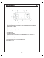 8
8
-
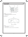 9
9
-
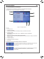 10
10
-
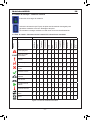 11
11
-
 12
12
-
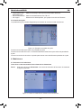 13
13
-
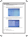 14
14
-
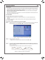 15
15
-
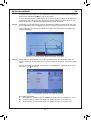 16
16
-
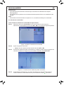 17
17
-
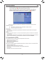 18
18
-
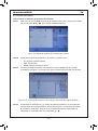 19
19
-
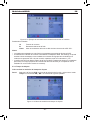 20
20
-
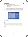 21
21
-
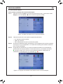 22
22
-
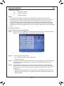 23
23
-
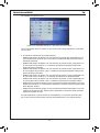 24
24
-
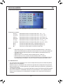 25
25
-
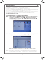 26
26
-
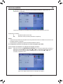 27
27
-
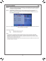 28
28
-
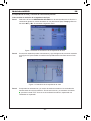 29
29
-
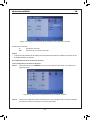 30
30
-
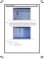 31
31
-
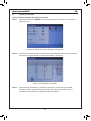 32
32
-
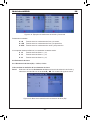 33
33
-
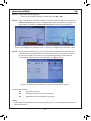 34
34
-
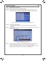 35
35
-
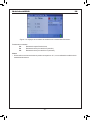 36
36
-
 37
37
-
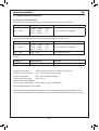 38
38
-
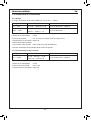 39
39
-
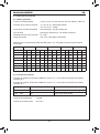 40
40
-
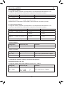 41
41
-
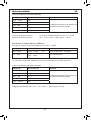 42
42
-
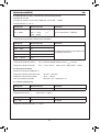 43
43
-
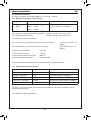 44
44
-
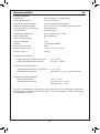 45
45
-
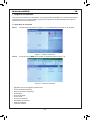 46
46
-
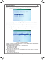 47
47
-
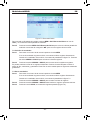 48
48
-
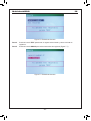 49
49
-
 50
50
-
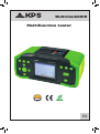 51
51
-
 52
52
-
 53
53
-
 54
54
-
 55
55
-
 56
56
-
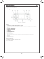 57
57
-
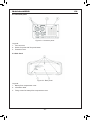 58
58
-
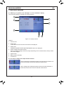 59
59
-
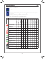 60
60
-
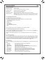 61
61
-
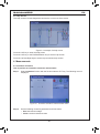 62
62
-
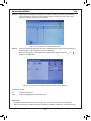 63
63
-
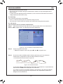 64
64
-
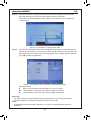 65
65
-
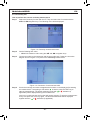 66
66
-
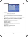 67
67
-
 68
68
-
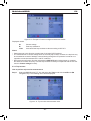 69
69
-
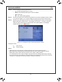 70
70
-
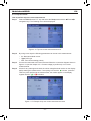 71
71
-
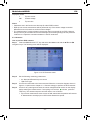 72
72
-
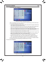 73
73
-
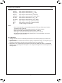 74
74
-
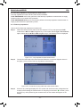 75
75
-
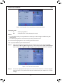 76
76
-
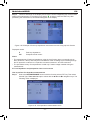 77
77
-
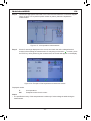 78
78
-
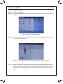 79
79
-
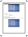 80
80
-
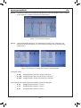 81
81
-
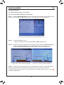 82
82
-
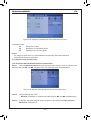 83
83
-
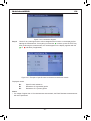 84
84
-
 85
85
-
 86
86
-
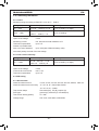 87
87
-
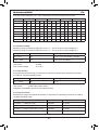 88
88
-
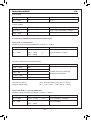 89
89
-
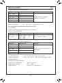 90
90
-
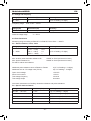 91
91
-
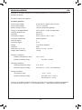 92
92
-
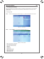 93
93
-
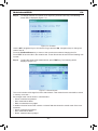 94
94
-
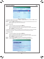 95
95
-
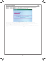 96
96
-
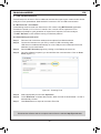 97
97
-
 98
98
-
 99
99
-
 100
100


KPS 20114251 Manual de usuario
- Categoría
- Probadores de redes de cable
- Tipo
- Manual de usuario
- Este manual también es adecuado para
En otros idiomas
- English: KPS 20114251 User manual
Documentos relacionados
Otros documentos
-
koban KIT E.V El manual del propietario
-
Sonel MPI-535 Manual de usuario
-
Sonel MPI-507 Manual de usuario
-
Sonel MPI-540-PV Manual de usuario
-
-
Sonel MPI-530-IT Manual de usuario
-
Gossen MetraWatt PROFITEST 2 Instrucciones de operación
-
-
DirekTronik 20114258 Guía del usuario