Kichler Lighting 42384AP Manual de usuario
- Tipo
- Manual de usuario

IMPORTANT SAFETY INSTRUCTIONS
LIGHTED BULB IS HOT!
WARNING: To reduce the risk of FIRE or INJURY TO PERSON:
• Turn off and allow to cool before replacing bulb.
• Bulb gets HOT QUICKLY! Contact switch only when turning off.
• DO NOT remain in light if skin feels warm. (Light is intense,
may cause “sunburn”)
• DO NOT look directly at lighted bulb.
• Keep materials away from bulb that may burn.
• Use ONLY with wattage specified or lower.
• DO NOT touch bulb at any time, use a soft cloth. Oil from skin
may damage bulb.
• DO NOT operate fixture with missing or damaged glass.
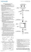
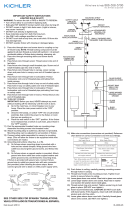
1) Pass fixture wire from center stem through stem and thread
end of stem to top of center stem.
2) Pass fixture wire through remaining stems and screw stems
together.
NOTE: Thread locking compound must be applied to all
stem threads as noted with symbol (3) to prevent accidental
rotation of fixture during cleaning, relamping, etc.
3) Pass fixture wire through end of swivel on canopy. Carefully
pull wires up through canopy. Thread swivel onto end of last
stem.
NOTE Align swivel to ceiling slope if needed.
4) TURN OFF POWER.
IMPORTANT: Before you start, NEVER attempt any work
without shutting off the electricity until the work is done.
a) Go to the main fuse, or circuit breaker, box in your
home. Place the main power switch in the “OFF”
position.
b) Unscrew the fuse(s), or switch “OFF” the circuit breaker
switch(s), that control the power to the fixture or room
that you are working on.
c) Place the wall switch in the “OFF” position. If the fixture
to be re placed has a switch or pull chain, place those in
the “OFF” position.
5) Find the appropriate threaded holes on mounting strap.
Assemble mounting screws into threaded holes.
6) Attach mounting strap to outlet box. (Screws not provided).
Mounting strap can be adjusted to suit position of fixture.
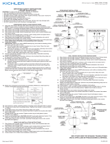
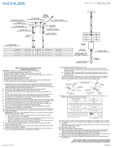
7) Grounding instructions: (See Illus. A or B).
A) On fixtures where mounting strap is provided with a
hole and two raised dimples. Wrap ground wire from
outlet box around green ground screw, and thread into
hole.
B) On fixtures where a cupped washer is provided. Attach
ground wire from outlet box under cupped washer and
green ground screw, and thread into mounting strap.
If fixture is provided with ground wire. Connect fixture
ground wire to outlet box ground wire with wire connector.
(Not provided.) After following the above steps. Never
connect ground wire to black or white power supply wires.
8) Make wire connections (connectors not provided.) Reference
chart below for correct connections and wire accordingly.
GREEN GROUND
SCREW
CUPPED
WASHER
A
B
OUTLET BOX
GROUND
FIXTURE
GROUND
DIMPLES
WIRE CONNECTOR
(NOT PROVIDED)
OUTLET BOX
GROUND
GREEN GROUND
SCREW
FIXTURE
GROUND
Connect Black or
Red Supply Wire to:
Connect
White Supply Wire to:
Black White
*Parallel cord (round & smooth) *Parallel cord (square & ridged)
Clear, Brown, Gold or Black
without tracer
Clear, Brown, Gold or Black
with tracer
Insulated wire (other than green)
with copper conductor
Insulated wire (other than green)
with silver conductor
*Note: When parallel wires (SPT I & SPT II)
are used. The neutral wire is square shaped
or ridged and the other wire will be round in
shape or smooth (see illus.)
Neutral Wire
Date Issued: 1/1/16
IS-42384-US
MOUNTING STRAP
ABRAZADERA DE
MONTAJE
CANOPY
ESCUDETE
STEM
VARILLA
KNURL KNOB
PERILLA ESTRADA
SWIVEL
UNIÓN GIRATORIA
3
3
SEE OTHER SIDE FOR SPANISH TRANSLATIONS.
VEA EL OTRO LADO DE TRADUCCIONES AL ESPAÑOL.
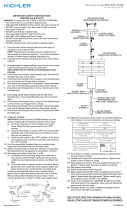
9) Push fixture to ceiling, carefully passing mounting screws
through holes in canopy.
10) Thread knurl knobs onto ends of mounting screws. Tighten
knurl knobs to secure fixture to ceiling.
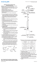
11) Pass hole in bracket on outer shade over socket.
12) Fit glass inside outer shade. Pass hole in top of glass over
socket.
12) Thread socket ring onto socket. (DO NOT over tighten.)
19) Insert recommended bulb. CAUTION: DO NOT touch bulb
with bare hands. If this happens, clean bulb with denatured
alcohol and a lint free cloth.
20) Fit glass sleever over bulb. Carefully thread glass sleeve
onto socket. (DO NOT over tighten.)
We’re here to help 866-558-5706
Hrs: M-F 9am to 5pm EST
GLASS
VIDRIO
BULB
BOMBILLA
GLASS SLEEVE
CAMISA DE VIDRIO
SOCKET RING
ANILLO DEL CASQUILLO
OUTER SHADE
PANTALLA EXTERIOR
CENTER STEM
VARILLA CENTRAL

INSTRUCCIONES IMPORTANTES DE SEGURIDAD
LA BOMBILLA ENCENDIDA ES CALIENTE
ADVERTENCIA: Para disminuir el riesgo de INCENDIO o LESIO-
NES A LAS PERSONAS:
• Apague y deje que se enfríe antes de cambiar la bombilla.
• La bombilla SE CALIENTA RÁPIDAMENTE. Use el interruptor
sólo para apagar.
• NO permanezca en la luz si siente caliente la piel. (La luz es
intensa y puede causar “quemaduras”).
• NO mire directamente a la bombilla encendida.
• Mantenga alejados de la bombilla los artículos que puedan
quemarse.
• Use SOLAMENTE con el vatiaje especificado o mas bajo.
• NO toque la bombilla en ningún momento, use una tela suave.
La grasa de la mano puede dañar la bombilla.
• NO haga funcionar el artefacto con la bombilla dañada o
faltante.
1) Pasar los alambres del artefacto desde el vástago central a
través del vástago y rosque el extremo del vástago a la
parte superior del vástago central.
2) Pase los alambres del artefacto a través del vástago y rosque
el extremo del vástago en la parte superior del cuerpo del
artefacto. NOTA: El compuesto para rosca estanca se debe
aplicar a todas las roscas del vástago como se notó con el
símbolo (3) para impedir la rotación accidental del artefacto
durante la limpieza, instalación de una bombilla nueva, etc.
3) Pase los alambres del artefacto hasta el final del junta
articulada en el escudete. Tire con cuidado los alambres a
través del escudete. Ahora enrosque la junta articulada
en el extremo del último vástago.
NOTA: mueva la junta articulada conforme a la pendiente
del cielorraso si es necesario.
4) APAGUE LA ALIMENTACIÓN ELÉCTRICA.
IMPORTANTE: Antes de comenzar, NUNCA trate de trabajar
sin antes desconectar la corriente hasta que el trabajo se
termine.
a) Vaya a la caja principal de fusibles, o interruptor o caja
de circuitos de su casa. Coloque el interruptor de la
corriente principal en posición de apagado “OFF”.
b) Desatornille el (los) fusible (s), o coloque el interruptor o
interruptores del breaker en posición de apagado “OFF”,
que controla (n) la corriente hacia el artefacto o habitación
donde está trabajando.
c) Coloque el interruptor de pared en posición de apagado
“OFF”. Si el artefacto que se va a reemplazar tiene un
interruptor o cadena que se jala, colóquelos en la
posición de apagado “OFF”.
5) Ensamble los tornillos de montaje en los orificios roscados
en la barra de montaje.
6) Unir la abrazadera de montaje a la caja de conexiones. (No
se proveen tornillos). La abrazadera de montaje puede
ajustarse para acomodar la posición del artefacto.
7) Instrucciones de conexión a tierra solamente para los
Estados Unidos.
(Vea la ilustracion A o B).
A) En las lámparas que tienen el fleje, de montaje con un
agujero y dos hoyue los realzados. Enrollar el alambre a
tierra de la caja tomacorriente alrededor del tornillo
verde y pasarlo por el aquiero.
B) En las lámparas con una arandela acopada. Fijar el
alambre a tierra de la caja tomacorriente del ajo de la
arandela acoada y tornillo verde, y paser por el fleje de
montaje.
Si la lámpara viene con alambre a tierra. Conecter el
alambre a tierra de la lámpara al alambre a tierra de la caja
tomacorriente con un conector de alambres (no incluido)
espués de seguir los pasos anteriores. Nunca conectar el
alambra a tierra a los alambres eléctros negro o blanco.
Date Issued: 1/1/16
IS-42384-US
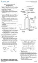
8) Haga les conexiones de los alambres (no se proveen los
connectores.) La tabla de referencia de abajo indica las
conexiones correctas y los alambres correspondientes.
9) Empuje el artefacto hacia el techo, pasando cuidadosamente
los tornillos de montaje a través de los orificios en el
escudete.
10) Asegure el artefacto al techo con las perillas estriadas.
11) Pase el agujero en el soporte en la pantalla exterior sobre el
casquillo.
12) Montar el vidrio dentro de la pantalla exterior. Pasar el
agujero en la parte superior del vidrio sobre el casquillo.
13) Rosque el anillo del casquillo en el casquillo. (NO apriete
excesivamente.)
14) Inserte la bombilla recomendada. PRECAUCIÓN: NO toque
la bombilla con las manos sin guantes. Si esto sucede, limpie
la bombilla con alcohol desnaturalizado y una tela sin pelusas.
15) Resbale la camisa de vidrio sobre la bombilla. Rosque
cuidadosamente la camisa de vidrio sobre el casquillo. (NO
apriete demasiado).
ARANDELA
CONCAVA
A
B
TIERRA DE LA
CAJA DE SALIDA
TORNILLO DE TIERRA,
VERDE
DEPRESIONES
TIERRA
ARTEFACTO
CONECTOR DE ALAMBRE
(NO SE PROVEE)
TIERRA DE LA
CAJA DE SALIDA
TORNILLO DE TIERRA,
VERDE
TIERRA
ARTEFACTO
Conectar el alambre de
suministro negro o rojo al
Conectar el alambre de
suministro blanco al
Negro Blanco
*Cordon paralelo (redondo y liso)
*Cordon paralelo (cuadrado y estriado)
Claro, marrón, amarillio o negro
sin hebra identificadora
Claro, marrón, amarillio o negro
con hebra identificadora
Alambre aislado (diferente del verde)
con conductor de cobre
Alambre aislado (diferente del
verde) con conductor de plata
*Nota: Cuando se utiliza alambre paralelo
(SPT I y SPT II). El alambre neutro es de forma
cuadrada o estriada y el otro alambre será de
forma redonda o lisa. (Vea la ilustracíón).
Hilo Neutral
SEE OTHER SIDE FOR ENGLISH TRANSLATIONS.
VEA EL OTRO LADO DE TRADUCCIONES AL INGLÉS.
We’re here to help 866-558-5706
Hrs: M-F 9am to 5pm EST
MOUNTING STRAP
ABRAZADERA DE
MONTAJE
CANOPY
ESCUDETE
STEM
VARILLA
KNURL KNOB
PERILLA ESTRADA
SWIVEL
UNIÓN GIRATORIA
3
3
GLASS
VIDRIO
BULB
BOMBILLA
GLASS SLEEVE
CAMISA DE VIDRIO
SOCKET RING
ANILLO DEL CASQUILLO
OUTER SHADE
PANTALLA EXTERIOR
CENTER STEM
VARILLA CENTRAL
-
 1
1
-
 2
2


Kichler Lighting 42384AP Manual de usuario
- Tipo
- Manual de usuario
en otros idiomas
- English: Kichler Lighting 42384AP User manual
Artículos relacionados
-
 Kichler Lighting 45478CH Manual de usuario
-
 Kichler Lighting 9557AZ Manual de usuario
-
 Kichler Lighting 43152AP Manual de usuario
-
 Kichler Lighting 43442NI Manual de usuario
-
 Kichler Lighting 44003NI Manual de usuario
-
 Kichler Lighting 43688NI Manual de usuario
-
 Kichler Lighting 44010MIZ Manual de usuario
-
 Kichler Lighting 44008MIZ Manual de usuario
-
 Kichler Lighting 44011MIZ Manual de usuario
-
 Kichler Lighting 43687NI Manual de usuario


