La página se está cargando...

GENERALIDADES
(Fig.1)
Notas:
C
la
hoja "Generalidades” que forma parte del
presente manual.
Estas fotocélulas caracterizadas por un diseño innovador y moderno
hacen una barrera óptica con rayos infrarrojos modulados e invisibles
a simple vista.
La fotocelula está equipada con un filtro antiparásito para motores
de corriente continua o alterna.
El haz de la fotocélula es estrecho para evitar fenómenos de reflexión
y para ser conforme a las normativas vigentes.
Los dos componentes estan repuestos en agradables y pequeños
contenedores que facilitan la instalación.
No es necesario el centraje, pueden fijarse a la pared o al pillar y
están equipadas con un filtro para los rayos del sol.
Las fotocélulas se instalan normalmente a las extremidades de la
abertura, con el receptor por un lado y el emisor por el otro; cuando
un objeto u otra cosa se encuentra en el medio del haz de rayos,
viene enviado un siñal al cuadro electrónico que bloquea e/o invierte
la marcha.
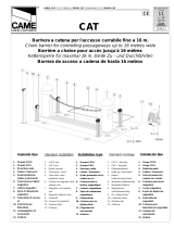
CONEXIÓN TABLERO DE BORNES
Si es necesario instalar dos pares de fotocélulas para obtener una
protección doble y es importante recordarse de que es incorrecto
instalar dos receptores en el mismo pilar por esto es necesario
cambiar la posición del transmisor con la del receptor.
INSTALACIÓN
)
5) Conectar los cables en el tablero de bornes, considerando que
en los bornes 3 y 4 del Receptor se obtiene, con la fotocélula
alimentada y centrada, un contacto normalmente cerrado.
6) Alimentar el Transmisor y el Receptor como en el esquema con
la tensión de 12V dc o 24 V ac / dc
REPUESTOS
ontenidor de plástico
Tarjeta Tx
Tarjeta Rx
Para un uso apropriado del producto y para
excluir cualquiera posibilidad de daños a
personas animales o cosas consultar
1) Quitar la tapa y destornillar el tornillo de enclaje.
2) Instalar la base al pillar o a la pared.
El tablero de bornes tiene que quedar en la parte inferior.
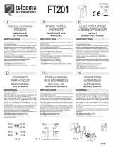
3) Respectar las alturas y la dirección instalando el receptor y el
transmisor uno en frente al otro, en el mismo eje y a la misma
altura.(fig.4)
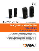
4) Entrada de los cables: romper el agujero según dimensiones
adecuadas al cable empleado (fig 2/3
Si la posición, la alineación y las conexiones están correctas, el
led rojo será encendido aun sin tapa (capacidad max. 6/7 mt)
Para mayores capacidades el led se encenderá solo insertando
la tapa (con lente incorporada).
Interrumpiendo el rayo entre Tx y Rx el led rojo tiene que
apagarse, el Relè de cerrado se pone abierto y entonces el
contacto entre los bornes 3 Y 4 tiene que abrirse.
Insertar las tapas de protección, haciendo cuidado a que sean
en adherencia y en posición y fijar con los tornillos en dotación.
ALLGEMEINES
Durch neues und modernes Design charakterisiert, das mit dem Rest der
Anlage harmoniert und eine optische Barriere aus modulierten
Infrarotstrahlen bildet, die mit bloßem Auge nicht sichtbar sind.
Die Lichtschranke besitzt eine Störungsabschirmung für Motoren mit
Gleichstrom und Wechselstrom.
Das Bündel der Lichtschranke ist so kreiert, daß es Reflexerscheinungen
verhindert und den herrschenden Normen entspricht.
Beide Komponenten sind in einem hübschen Behälter integriert, der nicht
sperrig ist und sich schnell installieren läßt.
Es bedarf keiner Zentrierung, sie kann an der Wand oder am Pfeiler
befestigt werden und ist gegen Sonneneinstrahlung abgesichert.
Normalerweise an den Seiten der Öffnung, mit dem Projektor auf einer
Seite und dem Empfänger auf der anderen, wenn ein Objekt oder etwas
anderes den in den Lichtkreis dringt, wird ein Signal an die
Kommandoeinheit geleitet, welche die Bewegung blockiert oder
invertiert.
ANSCHLÜSSE KLEMMBRETT (Fig 1)
Note:
ERSATZTEILE
Kunststoffhalter
Karte TX.
Karte RX.
Für eine optimale Nutzung des Produkts und um
jedmöglichen Schaden an Personen, Tieren und
Dingen auszuschließen, Siehe Blatt
"Allgemeines", das integrierender Bestandteil
des vorliegenden Handbuchs ist.
Soweit notwending, zwei Lichtschrankenpaare montieren, um einen
weiteren Schutz zu bekommenn; die Befestigung von zwei Empfängern
auf demselben Pfeiler vermeiden indem man die Positionen von Projektor
und Empfänger invertiert.
INSTALLATION
1) Den Deckel abnehmen und die entsprechende Befestigungschraube
aufdrehen.
2) Das Platte an der Wand oder am Pfeiler mit den beiden Schrauben
u./o. Dübel befestigen
Das Klemmbrett muß am unteren Teil angebracht sein.
3) Höhen und Richtung respektieren, indem Übertragungsgerät und
Empänger in Frontalposition auf derselben Achse und auf derselben
Höhe befestigt werden. (Bild 4)
4) * Für den Eingang der Kabel: das vorgezeichnete Montageloch
durchstoßen um eine Breite die zum Kabel geeignet ist. (Bild 2/3)
5) Die Drähte am Klemmbrett anschließen, dabei beachten Sie, daß ein
geschlossener Kontakt auf den Klemmen 4 und 5 des RX, bei
versorgter und zentrierter Lichtschranke, normalerweise besteht.
6) Ansender und Empfänger mit 12V dc oder 24V ac / dc Spannung
versorgen, wie auf dem Plan vorgesehen.
Wenn die Positionierung, die Versorgung und die Spannung
korrekt sind, wird das rote Licht (LED) des Empfängers auch
ohne Deckel angeschaltet sein ( Tragkraft max. 6/7 mt.).
Bei schwereren Lasten stellt sich das Licht (LED) nur ab, wenn
der Deckel abgesetzt ist.
Wird der Strahl zwischen TX und RX unterbrochen, muß die rote
LED sich abschalten, das Relais muß sich umstellen und der
Kontakt auf den Klemmen 3 und 4 sich öffnen.
Schutzdeckel einsetzen und sichergehen, daß sie wohl haften
und mit den aufgestatteten Schrauben befestigen.
GENERAL INSTRUCTIONS
CONNECTION HOLDFAST (Fig. 1)
Note:
SPARE PARTS
Plastic box.
Diagram TX.
Diagram RX.
For a proper use of this product and to avoid any
damages to people, animals or things, refer to
the paper "General Instructions" that is part of
this manual.
These photocells are characterized by a modern and innovative design
INSTALLATION
.
They create an optical barrier by generating modulated infrared rays
which are invisible to the naked eye.
The photocell is equipped with an anti-interference shield for motors
running on A.C. or D.C.
The photocell beam is narrow to avoid reflection and to comply with
current regulations.
The two components are incorporated in a nice housing, small in size and
easy to install.
It doesn't need to be centered, it may be installed on a wall or on the pillar
and it is shielded from the sun rays.
They are usually positioned on the opening sides, with the projector on
one side and the receiver on the other one, when an object or something
else breaks in the light beam, a signal is sent to the control unit which will
stop and/or invert the motion.
It is necessary, it is possible to install two pairs of photocells to get a
double protection.
Remember that it is incorrect to install two receivers on the same pillar,
therefore switch the position between the projector and the receiver.
1) Remove the cover and unscrew it.
2) Fasten the base to the wall or to the pillar.
3) While fixing the TX and the RX in frontal position on the same axle
and at the same height take into consideration heights and direction
(Fig. 4)
4) Cables entrance: break through the pre-hole according to the
dimensions of the cable used (Fig. 2/3 )
5) Connect the wires of the terminal boards taking into account that on
the terminals 3 and 4 of the RX we have, in case of a feeded and
centred photocell, a normally closed contact.
6) Power both the Transmitter and the Receiver, as per diagram, with
voltage of 12V dc or 24 V ac / dc.
If position, alignement and connections are correct, the red led of
the receiver is on even without cover (max range 6/7 mt).
For higher capacities, the led will switch on only inserting the cover
(with the lens incorporated)
Interrupting the ray between TX and RX, the red led must turn off,
the relay has to switch on and the contact on terminals 3 and 4
must open.
Insert the protection covers making sure that they are perfectly
adhrent and fix them with screws.
GENERALITE
Caractérisées par un design novateur et moderne, installées avec le
reste du matériel , elles créent une barrière de protection optique à
rayons infrarouges invisibles.
Les photocellules sont munies d'un philtre antiparasite pour éviter les
perturbations avec les moteurs que ce soit en courant continu ou
alternatif (norme EMC).
Le faisceau des photocellules répond aux normes en vigueur, il est
étroit pour éviter les phénomènes de réflexion.
Les deux cartes électroniques sont intégrés dans un boîtier très
esthétique, de petite dimension, et facile à installer.
Installées sur les piliers côtés extérieur , il y aura d'un côté la cellule
émettrice et de l'autre la cellule réceptrice, quand une personne, un
véhicule, voir un objet interrompt le faisceau entre les cellules un
signal est envoyé à la carte de gestion qui bloque et/ou inverse le
mouvement du portail.
CONNEXION (Fig.1)
S'il est nécessaire de monter deux paires de photocellules pour avoir
une double protection, le deuxième jeu devra être inversé par rapport
au premier, ne pas placer du même côté 2 cellules réceptrices ou 2
cellules émettrices il y a un risque de perturbation.
INSTALLATION
1) Enlever le couvercle et dévisser la vis de fixation
2) Fixer l'embase du boîtier au mur ou au poteau.
3) Respecter les hauteurs et la direction lorsqu'on fixe la cellule TX
(émettrice) et la cellule RX (réceptrice) face à face, un bon
alignement est important. (Fig. 4)
4) Pour le passage de câbles, il faut utiliser le pré-perçage selon les
dimension du câble (Fig. 2/ 3)
5) Brancher les fils à partir des borniers de connexion en tenant
compte que sur les bornes 3 et 4 de la RX on a une fois la
photocellule alimentée et centrée, un contact normalement
fermé.
6) Alimenter aussi bien l'émetteur que le Récepteur comme sur le
schéma avec une tension de 12V dc ou 24V ac / dc selon votre
système.
Notes : Si lors de l'alimentation, l'alignement et les branchements
sont corrects, la led rouge de la cellule réceptrice (RX) sera
allumée, attention, sans le couvercle la portée maximum sera
de 6 à7m.
Pour une distance supérieure la led s'allumera uniquement en
mettant le couvercle.
La portée max, avec de bonnes conditions climatiques et son
couvercle est de 40m.
En interrompant le rayon entre la cellule TX et RX, la led rouge
doit s'éteindre, le relais doit commuter, vous l'entendrez
''cliquer'' le contact sur les bornes 3 et 4 s'ouvrira.
Insérer les couvercles de protection partie haute en premier et
appuyez pour les clipser correctement.
Assurez vous de la parfaite étanchéité de vos cellules et fixez
avec les vis en dotation.
PARTIES DES RECHANGES
Boîtier en plastique
Carte TX
Carte RX
Pour une bonne utilisation du produit et pour
éviter toute possibilité de dommages aux
personnes, aux animaux et aux biens, se
référer au paragraphe "Généralité" qui fait
partie intégrante du manuel d'installation.
.
.
ATENCION
ACHTUNG
WARNING
ATENTION
Clamp Description
1- 2 Power supply 12V dc or 24 V ac/dc
3- 4 Relais connection N.C.
1- 2 Power supply 12V dc or 24 V ac/dc
Bornes Description
1 - 2 Alimentation 12V dc ou 24 V ac/dc
3 - 4 Contact relais N.C.
1 - 2 Alimentation 12V dc ou 24 V ac/dc
Klemm Beschreibung
1 - 2 Speisung 12V dc und 24 V ac/dc
3 - 4 Anschluß Relé N.C.
1 - 2 Speisung 12V dc und 24 V ac/dc
Borne Descripcion
1 - 2 Alimentación 12V dc o 24 V ac/dc
3 - 4 Contacto Rele N.C.
1 - 2 Alimentación 12V dc o 24 V ac/dc
RX
TX
RX
TX
RX
TX
RX
TX
ESPAÑOL
DEUTSCHENGLISH
FRANÇAIS
1/2