Toro 117–3600 Guía de instalación
- Categoría
- Cortadoras de césped
- Tipo
- Guía de instalación
Este manual también es adecuado para

FormNo.3361-320RevB
ChuteGateKit
GrandStand
™
MowersandZMaster
®
G3Mowers
ModelNo.117–3600
InstallationInstructions
Safety
SafetyandInstructionalDecals
Safetydecalsandinstructionsareeasilyvisibletotheoperatorandarelocatednearanyareaof
potentialdanger.Replaceanydecalthatisdamagedorlost.
108-4102
1.Operatordischargecontrol3.Closed
2.Open4.ReadtheOperator’s
Manual.
108-7250
©2008—TheToro®Company
8111LyndaleAvenueSouth
Bloomington,MN55420
Registeratwww.Toro.com.
OriginalInstructions(EN)
PrintedintheUSA.
AllRightsReserved

Installation
LooseParts
Usethechartbelowtoverifythatallpartshavebeenshipped.
ProcedureDescription
Qty.
Use
1
Nopartsrequired
–
Removetheexistingsidedischarge
chute.
Sidedischargechute
1
Bolt,(5/16x7–1/2inches)
1
Locknut,(5/16inch)
1
Plasticspacer1
2
Spring
1
Installthesidedischargechutewith
gate.
Handleassembly1
Bolt,(3/8x1inch)(Selftapping)
2
3
Plasticcabletie1
InstallthehandletoaGrandStand
Mower.
Handleassembly1
Bolt,(3/8x1inch)
2
Plasticcabletie1
4
Adhesivebackmount1
InstallthehandletoaZMasterG3
Mower.
5
Trashbag1Installthetrashbag.
6
Internationaldecal1
Installthedecalforinternationalmowers
only.
1
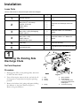
RemovingtheExistingSide
DischargeChute
NoPartsRequired
Procedure
1.DisengagethePTO,settheparkingbrake,andchock
orblockthedrivewheels.
2.Turnofftheengine,removethekey,andwaitforall
movingpartstostopbeforeleavingtheoperating
position.
3.Removethelocknut,bolt,springandspacerholding
thedeectortothepivotbrackets(Figure1).
Removethegrassdeector.
Figure1
1.Bolt
5.Springinstalled
2.Spacer6.GrassDeector
3.Locknut
7.Lendofspring,place
behinddeckedgebefore
installingbolt
4.Spring8.Jhookendofspring
2

2
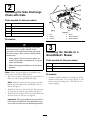
InstallingtheSideDischarge
ChutewithGate
Partsneededforthisprocedure:
1
Sidedischargechute
1
Bolt,(5/16x7–1/2inches)
1
Locknut,(5/16inch)
1Plasticspacer
1
Spring
Procedure
Anuncovereddischargeopeningcouldallow
thelawnmowertothrowobjectsinthe
operator’sorbystander’sdirectionandresult
inseriousinjury.Also,contactwiththeblade
couldoccur.
•Neveroperatethelawnmowerunlessyou
installacoverplate,amulchplate,oragrass
chuteandcatcher.
•Makesurethegrassdeectorisinthedown
position.
Note:Ensurethegrassdeectorisinstalledinthe
lowerholesinthemowerdeckbrackets.
1.Placethenewspacerandspringontograssdeector.
Placeoneendofspringbehinddeckedge.
Note:Makesuretheendofthespringisinstalled
behindthedeckedgebeforeinstallingtheboltas
showninFigure2.
2.Installboltandnutinthelowerhole.Placetheend
ofthespringaroundthegrassdeector(Figure2).
3.Tightenthenutuntiltheendoftheboltisushwith
theendofthenut.Donotovertighten.
Important:Thegrassdeectormustbeableto
lowerdownintoposition.Liftthedeectorup
totestthatitlowersintothefulldownposition.
Figure2
1.Bolt
4.Spring
2.Spacer5.Springinstalled
3.Locknut
6.GrassDeector
3
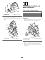
InstallingtheHandletoa
GrandStand
™
Mower
Partsneededforthisprocedure:
1Handleassembly
2
Bolt,(3/8x1inch)(Selftapping)
1Plasticcabletie
Procedure
1.Installthehandleassemblytotherightsideofthe
machinewith2bolts(3/8x1inch)(Figure3).The
boltsarethreadformingbolts.Theholesdonot
requiretapping.
3

Figure3
1.Bolt,(3/8x1inch)3.Rightsideofmachine
2.Handleassembly
2.Fastenthecablestothemachinewithaplastictie
(Figure4).Ensurethecablesdonotcontactthe
reartire.
Figure4
1.Handleassembly2.Plasticcabletie
4
InstallingtheHandletoaZ
Master
®
G3Mower
Partsneededforthisprocedure:
1Handleassembly
2
Bolt,(3/8x1inch)
1Plasticcabletie
1Adhesivebackmount
Procedure
1.Installthehandleassemblytotherightsideofthe
machinewith2bolts(3/8x1inch)(Figure5).
Figure5
1.Bolt,(3/8x1inch)3.Rightsideofthemachine
2.Handleassembly
2.Installtheadhesivebackplasticmountonasmooth
cleansurface.Threadthecabletiethroughthe
plasticmountandsecurethecableswiththecable
tie(Figure6).
4

Figure6
1.Handleassembly2.Plasticcabletieandplastic
mount
5
InstallingtheTrashBag
Partsneededforthisprocedure:
1Trashbag
Procedure
Installthetrashbagintotheslotsinthehandleassembly
(Figure7).
Figure7
1.Trashbag
2.Slotinhandleassembly
6
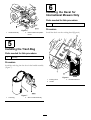
InstallingtheDecalfor
InternationalMowersOnly
Partsneededforthisprocedure:
1Internationaldecal
Procedure
Installthedecalovertheexistingdecal(Figure8).
Figure8
1.Existingdecal3.Internationaldecal
2.Handle
5

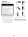
Operation
UsingtheChuteGate
Thechutegatedoesnotsealthedischarge
opening.Grassandobjectsmaybethrownin
abystander’sdirectionandresultinserious
injury.
•Beawareofthemowerdischargedirection
anddonotpointitatanyone.
•Removeobstaclessuchasrocks,treelimbs,
etc.fromthemowingarea.
•Neverputyourhandsorfeetunderthe
mowerordischargearea.
•Nevertrytoclearthedischargeareaor
mowerbladesunlesstheengineisoffand
thekeyisremoved.
Usethechutegatetotemporarilystopordeectgrass
clippingsawayfromsidewalks,parkinglots,patios,or
anywhereyoudonotwantgrassclippingstoland.The
chutegatehas3positions:open,45degreeangle,and
closed.
•Rotatethechutegatehandletotheopenpositionto
allowgrassclippingstodischarge(FigureFigure9).
•Rotatethechutegatehandletothe45degreeangle
todeectthegrassclippings(FigureFigure9).
•Rotatethechutegatehandletotheclosedposition
tostopthegrassclippings(FigureFigure9).
Figure9
1.Chutegateopen3.Chutegateclosed
2.Chutegateat45degree
angle
6

FormNo.3361-320RevB
Kitdepuertadelconductodedescarga
CortacéspedesGrandStand
™
yZMaster
®
G3
Nºdemodelo117–3600
Instruccionesdeinstalación
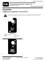
Seguridad
Pegatinasdeseguridadeinstrucciones
Laspegatinasdeseguridadeinstruccionesestánalavistadeloperadoryestánubicadascercade
cualquierzonadepeligropotencial.Sustituyacualquierpegatinaqueestédañadaoquefalte.
108-4102
1.Controldedescargadel
operador
3.Cerrada
2.Abierta4.LeaelManualdel
operador.
108-7250
©2008—TheToro®Company
8111LyndaleAvenueSouth
Bloomington,MN55420
Registresuproductoenwww.Toro.com.
Traduccióndeloriginal(ES)
ImpresoenEE.UU.
Reservadostodoslosderechos

Instalación
Piezassueltas
Utilicelatablasiguienteparavericarquenofaltaningunapieza.
Procedimiento
DescripciónCant.
Uso
1
Nosenecesitanpiezas
–
Retireelconductodedescargalateral
actual.
Conductodedescargalateral
1
Perno,(5/16x7–1/2pulgadas)
1
Contratuerca,(5/16inch)
1
Espaciadordeplástico1
2
Muelle1
Instaleelconductodedescargalateral
conpuerta.
Conjuntodelapalanca
1
Perno,(3/8x1inch)(Tornillos
penetrantes)
2
3
Sujetacablesdeplástico
1
Instalelapalancaenuncortacésped
GrandStand.
Conjuntodelapalanca
1
Perno,(3/8x1inch)
2
Sujetacablesdeplástico
1
4
Soporteautoadhesivo
1
InstalelapalancaenuncortacéspedZ
Master®G3.
5
Papelera1Instalelapapelera.
6
Pegatinainternacional1
Instalelapegatinaparacortacéspedes
internacionalessolamente.
1
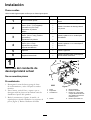
Retiradadelconductode
descargalateralactual
Nosenecesitanpiezas
Procedimiento
1.Desengranelatomadefuerza,pongaelfreno
deestacionamientoycalceobloqueelasruedas
motrices.
2.Pareelmotor,retirelallaveyespereaquese
detengantodaslaspiezasenmovimientoantesde
abandonarelpuestodeloperador.
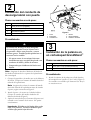
3.Retirelacontratuerca,elperno,elmuelleyel
espaciadorquesujetaneldeectoralossoportesde
pivote(Figura1).Retireeldeectordehierba.
Figura1
1.Perno5.Muelleinstalado
2.Espaciador
6.Deectordehierba
3.Contratuerca
7.ExtremoenLdelmuelle;
coloquedetrásdelreborde
delaplataformaantesde
instalarelperno
4.Muelle8.ExtremodelmuelleenJ
2

2
Instalacióndelconductode
descargalateralconpuerta
Piezasnecesariasenestepaso:
1
Conductodedescargalateral
1
Perno,(5/16x7–1/2pulgadas)
1
Contratuerca,(5/16inch)
1Espaciadordeplástico
1Muelle
Procedimiento
Sielhuecodedescargasedejadestapado
elcortacéspedpodríaarrojarobjetoshacia
eloperadorohaciaotraspersonasycausar
lesionesgraves.Tambiénpodríaproducirseun
contactoconlacuchilla.
•Nooperenuncaelcortacéspedsintener
instaladounatapa,unaplacadepicadooun
conductodehierbaybolsaderecortes.
•Compruebequeeldeectordehierbaestá
bajado.
Nota:Asegúresedeinstalareldeectordehierbaen
lostaladrosinferioresdelossoportesdelaplataforma
delcortacésped.
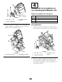
1.Coloqueelespaciadoryelmuellenueveneldeector
dehierba.Coloqueunextremodelmuelledetrásdel
rebordedelaplataforma.
Nota:Asegúresedecolocarelextremodelmuelle
detrásdelrebordedelaplataformaantesdeinstalar
elperno,segúnsemuestraenFigura2.
2.Instaleelpernoylatuercaeneltaladroinferior.
Coloqueelextremodelmuellealrededordel
deectordehierba(Figura2).
3.Aprietelatuercahastaqueelextremodelpernoesté
enrasadoconelextremodelatuerca.Noapriete
excesivamente.
Importante:Eldeectordehierbadebepoder
bajarasuposición.Levanteeldeectorpara
vericarquepuedebajardeltodo.
Figura2
1.Perno4.Muelle
2.Espaciador5.Muelleinstalado
3.Contratuerca6.Deectordehierba
3
Instalacióndelapalancaen
uncortacéspedGrandStand
™
Piezasnecesariasenestepaso:
1
Conjuntodelapalanca
2
Perno,(3/8x1inch)(T ornillospenetrantes)
1
Sujetacablesdeplástico
Procedimiento
1.Instaleelconjuntodelapalancaenelladoderecho
delamáquinacon2pernos(3/8x1inch)(Figura3).
Lostornillossontornillosqueformanrosca.Hoyos
nonecesitanrosca.
3

Figura3
1.Perno,(3/8x1inch)
3.Ladoderechodela
máquina
2.Conjuntodelapalanca
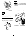
2.Sujeteloscablesalamáquinaconunsujetacablesde
plástico(Figura4).Asegúresedequeloscablesno
puedentocarelneumáticotrasero.
Figura4
1.Conjuntodelapalanca2.Sujetacablesdeplástico
4
Instalacióndelapalancaen
uncortacéspedZMaster
®
G3
Piezasnecesariasenestepaso:
1
Conjuntodelapalanca
2
Perno,(3/8x1inch)
1
Sujetacablesdeplástico
1
Soporteautoadhesivo
Procedimiento
1.Instaleelconjuntodelapalancaenelladoderecho
delamáquinacon2pernos(3/8x1inch)(Figura5).
Figura5
1.Perno,(3/8x1inch)
3.Ladoderechodela
máquina
2.Conjuntodelapalanca
2.Instaleelsoporteautoadhesivodeplásticosobre
unasupercielisaylimpia.Paseelsujetacables
porelsoportedeplásticoysujeteloscablesconel
sujetacables(Figura6).
4

Figura6
1.Conjuntodelapalanca2.Sujetacablesdeplásticoy
soportedeplástico
5
Instalacióndelapapelera
Piezasnecesariasenestepaso:
1Papelera
Procedimiento
Instalelapapeleraenlasranurasdelconjuntodela
palanca(Figura7).
Figura7
1.Papelera2.Ranuradelconjuntodela
palanca
6
Instalacióndelapegatinapara
cortacéspedesinternacionales
solamente
Piezasnecesariasenestepaso:
1Pegatinainternacional
Procedimiento
Instalelapegatinasobrelapegatinaactual(Figura8).
Figura8
1.Pegatinaexistente3.Pegatinainternacional
2.Palanca
5

Operación
Usodelapuertadelconducto
dedescarga
Lapuertadelconductonosellalaaberturadel
conductodedescarga.Puedensalirlanzados
hierbayotroobjetoshaciaeloperadorohacia
otraspersonasycausarlesionesgraves.
•Sepasiempreelsentidodedescargadel
cortacéspedynoorienteladescargahacia
nadie.
•Retirecualquierobstáculo,comopor
ejemplopiedras,ramasdeárboles,etc.,de
lazonadesiega.
•Nocoloquenuncalasmanosolospies
debajodelcortacéspedodelazonade
descarga.
•Nointentenuncadespejarlazonade
descargaolascuchillasdelcortacéspedsin
antespararelmotoryretirarlallave.
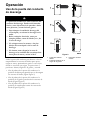
Utilicelapuertadelconductoparadetenerodesviar
temporalmentelosrecortesdehierbaparaqueno
caiganenaceras,aparcamientos,patiosuotrossitios
dondenoconvienequecaigan.Lapuertatiene3
posiciones:abierta,ángulode45grados,ycerrada.
•Girelapalancadelapuertadelconductoala
posicióndeabiertaparapermitirquesedescarguen
losrecortesdehierba(FiguraFigura9).
•Girelapalancadelapuertadelconductoala
posiciónde45gradosparadesviarlosrecortesde
hierba(FiguraFigura9).
•Girelapalancadelapuertadelconductoala
posicióndecerradapararetenerlosrecortesde
hierba(FiguraFigura9).
Figura9
1.Puertadelconducto
abierta
3.Puertadelconducto
cerrado
2.Puertadelconductoenun
ángulode45grados
6
-
 1
1
-
 2
2
-
 3
3
-
 4
4
-
 5
5
-
 6
6
-
 7
7
-
 8
8
-
 9
9
-
 10
10
-
 11
11
-
 12
12


Toro 117–3600 Guía de instalación
- Categoría
- Cortadoras de césped
- Tipo
- Guía de instalación
- Este manual también es adecuado para
en otros idiomas
- English: Toro 117–3600 Installation guide
Artículos relacionados
-
Toro Operator-Controlled Discharge Chute Kit, GrandStand Mower Guía de instalación
-
-
-
-
Toro Trash Bag Kit, GrandStand Mower Guía de instalación
-
-
Toro TimeMaster 30in Lawn Mower Manual de usuario
-
-
-