Sanus BXT2 Guía de instalación
- Categoría
- Soportes de pared para panel plano
- Tipo
- Guía de instalación
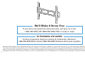
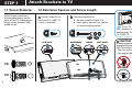
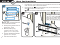
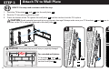
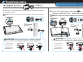
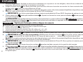
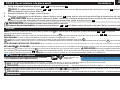
El Sanus BXT2 es un soporte de pared para televisores que ofrece una variedad de características para que disfrutes de tu televisor al máximo. Con su construcción resistente y su capacidad para soportar televisores de hasta 250 libras, el BXT2 es perfecto para televisores grandes y pesados. También cuenta con un sistema de gestión de cables integrado para mantener tus cables ordenados y fuera de la vista.
El Sanus BXT2 es un soporte de pared para televisores que ofrece una variedad de características para que disfrutes de tu televisor al máximo. Con su construcción resistente y su capacidad para soportar televisores de hasta 250 libras, el BXT2 es perfecto para televisores grandes y pesados. También cuenta con un sistema de gestión de cables integrado para mantener tus cables ordenados y fuera de la vista.


-
 1
1
-
 2
2
-
 3
3
-
 4
4
-
 5
5
-
 6
6
-
 7
7
-
 8
8
-
 9
9
-
 10
10
-
 11
11
-
 12
12
-
 13
13
-
 14
14
-
 15
15
-
 16
16
-
 17
17
-
 18
18
-
 19
19
-
 20
20
-
 21
21
-
 22
22
-
 23
23
-
 24
24


Sanus BXT2 Guía de instalación
- Categoría
- Soportes de pared para panel plano
- Tipo
- Guía de instalación
El Sanus BXT2 es un soporte de pared para televisores que ofrece una variedad de características para que disfrutes de tu televisor al máximo. Con su construcción resistente y su capacidad para soportar televisores de hasta 250 libras, el BXT2 es perfecto para televisores grandes y pesados. También cuenta con un sistema de gestión de cables integrado para mantener tus cables ordenados y fuera de la vista.
En otros idiomas
- English: Sanus BXT2 Installation guide
Documentos relacionados
-
Sanus VLT16 Manual de usuario
-
-
-
-
-
-
-
-
-