Viking RVMTK Guía de instalación
- Categoría
- Microondas
- Tipo
- Guía de instalación
Este manual también es adecuado para

Installation Guide
Microwave Built-In Trim Kit

2
E
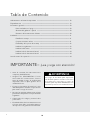
Table of Contents
IMPORTANT–
Please Read and Follow!
Warnings & Important Information ———————————————————————— 2
Specifications ————————————————————————————————— 3
General Information ——————————————————————————————— 4
Parts Included in the Kit ————————————————————————— 4
Cabinet or Wall Cutout —————————————————————————— 4
Electrical Outlet Location ————————————————————————— 4
Installation ——————————————————————————————————— 5
Mounting Template ——————————————————————————— 5
Bottom Duct Assembly —————————————————————————— 6
Mounting Bracket Assembly ——————————————————————— 6
Cabinet Installation ——————————————————————————— 7
Frame Assembly ————————————————————————————— 7
Side Decoration Assembly (For Surface Mount Only) ————————————— 8
Over Oven Installation —————————————————————————— 8
Performance Checklist ————————————————————————————— 8
• Before beginning, please read these
instructions completely and carefully.
• Be sure to DISCONNECT THE PLUG of the
microwave oven from the electrical outlet
before installing the built-in trim kit. Remove
the turntable from the oven cavity.
• Because the kit includes metal parts, caution
should be used in handling and installation
to avoid the possibility of injury.
• Do not remove permanently affixed labels,
warnings, or plates from the product. This
may void the warranty.
• Please observe all local and national codes
and ordinances.
• The installer should leave these instructions
with the consumer who should retain for local
inspector’s use and for future reference.
WARNING
This built-in trim kit is designed for use ONLY
with microwave ovens specifying built-in trim
kit RDMTK302 on the rating label on the left
side wall of the oven cavity.

E
3
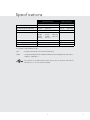
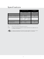
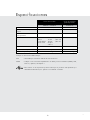
Microwave Oven Built-In Trim Kit
RVM320 / CRVM320 RVMTK330
Overall Width 24" (60.9 cm) 29-1/2" (74.9 cm)
Overall Height from Bottom 13-3/8" (33.9 cm) 17-1/4" (43.7 cm)
Overall Depth from Rear 19-1/8" (48.7 cm) NA
Oven Interior Width
Height
Depth
Overall
17-3/8"
10-1/2"
18-5/8"
2.0 cu. ft.
(44.1 cm)
(26.6 cm)
(47.3 c m)
NA
Electrical Requirements 120VAC/60 Hz NA
Max. Amp Usage 1.5 KW 13 amps NA
Approx. Shipping Wt. 46 lbs. (20.9 kg) 15 lbs. (6.9 kg)
In compliance with standards set by:
FCC – Federal Communications Commission Authorized.
DHHS – Complies with Department of Health and Human Services (DHHS) rule, CFR, Title 21,
Chapter I, Subchapter J.
– This symbol on the Rating label means the product is listed by Underwriters
Laboratories, Inc. for use in USA or Canada.
Specifications

4
E
General Information
4
E
14-1/4" (361.95 mm)
Minimum Cutout Opening Width 27-3/4" (704.9 mm)
Minimum Cutout Opening Height 16-9/16" (420.7 mm)
Maximum Cutout Opening Height 16-13/16" (427 mm)
Maximum Cutout Opening Width 28" (711.2 mm)
Distance between holes A9.1" (231.2 mm)
14" (355.6 mm)
Center Line
Floor Line of Cutout Opening
BUILT-IN TRIM KIT
SURFACE MOUNTING TEMPLATE
FOR DESIGNER SERIES MICROWAVE OVEN
TINSKB180MRR0
1/4"
(6.2 mm)
1/4"
(6.2 mm)
1. Align the Surface Mounting Template center line with the
center of the cabinet. Align the Floor Line with the bottom
of the cabinet at the desired height. Tape it into place.
2. Predrill 4 holes marked A with a ¹₁₆" drill bit.
3. Cut the cabinet opening between the minimum and
maximum cutout opening lines. Be careful to cut precisely
along the Floor Line of the cutout.
4. Remove template from the cabinet.
3-15/16" (100 mm)
7
2
1) Frame Assembly: QTY 1 2) Bottom Duct Assembly: QTY 1
3) Mouting Bracket: QTY 2 4) SIDE DECORATION: QTY 2
(SURFACE MOUNTING ONLY)
3
1) Frame Assembly: QTY 1 2) Bottom Duct Assembly: QTY 1
3) Mouting Bracket: QTY 2 4) SIDE DECORATION: QTY 2
(SURFACE MOUNTING ONLY)
6
1) Frame Assembly: QTY 1 2) Bottom Duct Assembly: QTY 1
3) Mouting Bracket: QTY 2 4) SIDE DECORATION: QTY 2
(SURFACE MOUNTING ONLY)
1
1) Frame Assembly: QTY 1 2) Bottom Duct Assembly: QTY 1
3) Mouting Bracket: QTY 2 4) SIDE DECORATION: QTY 2
(SURFACE MOUNTING ONLY)
4
5
4-3/16" (106.4 mm)
FLOOR LINE OF CUTOUT OPENING
BUILT-IN TRIM KIT
FLUSH MOUNTING TEMPLATE
FOR DESIGNER SERIES MICROWAVE OVEN
CABINET CUTOUT LINE
CABINET CUTOUT LINE
CENTER LINE
TINSKB181MRR0
1. Align the Flush Mounting Template center line with the center of the
cabinet. Align the Floor Line with the bottom of the cabinet at the
desired height. Tape it in place.
2. Cut the cabinet opening along the three Cabinet Cutout Lines and
the Floor Line.
3. Install two Side Spacers (see FIGURE 1) and one Bottom Spacer (see
FIGURE 2) as specified in FIGURE 3. Be sure to offset all three spacers
by 1⁹₁₆" from the front surface of the cabinet.
4. Cut out the Side Spacer Templates (R and L) and align the indicated
edge to the corresponding Side Spacer (see FIGURE 3). Be careful to
align the Floor Line to the bottom edges of the Side Spacers.
5. Predrill two holes indicated “A“ in Side Spacer - R with a ¹₁₆" drill bit.
6. Predrill two holes indicated ”B“ in Side Spacer - L with a ¹₁₆" drill bit.
7. Remove template from the cabinet.
SIDE SPACER TEMPLATE - L
SIDE SPACER TEMPLATE - R
FIGURE 1
Side Spacer (2 required)
Must protrude from edge of cabinet
cutout towards center as shown.
Align Side Spacer-L to this line
Align Side Spacer-R to this line
Cutout Opening Height 17-5/16" (439.8 mm)
CABINET CUTOUT LINE
Edges to align Side Spacer Templates (R and L)
Bottom Spacer centered with cabinet cutout
1-9/16" (39.7 mm)
Bottom and Side
Spacer (R and L) Offset
FIGURE 3
Side Spacer - L Side Spacer - R
14" (355.9 mm)
Distance between holes A9.1" (231.2 mm)
Cutout Opening Width 29-5/8" (752.5 mm)
14-13/16" (376.2 mm)
13/16" Min.
15/16 Max.
13-1/2" min. height
FIGURE 2
Bottom Spacer (1 required) ¹₄" plywood
24" min. width
27-7/8" max. width
1/4" (6.35 mm)1/4" (6.35 mm)
8
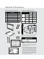
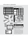
Parts Included in the Kit
Item Part Name QTY
1
Frame Assembly 1
2
Bottom Duct 1
3
Mounting Bracket 2
4
Screw A :1-3/16" length 2
5
Screw B: 1-3/4" length 4
6
Side Decoration
(Surface Mount Only)
2
7
Surface Mounting Template 1
8
Flush Mounting Template 1
Electrical Outlet Location
CAUTION
Outlet should NOT be in the shaded area as
indicated on figure 1.
1
figure
4"(10.2 cm)
4"(10.2 cm)
6"(15.2 cm)
NOTES:
• IftheDepth(C)dimensionisgreaterthan21"
(53.3 cm), the outlet location maybe inany
areaontherearwall.
• Theooroftheopeningshouldbeconstructed
ofplywoodstrongenoughtosupporttheweight
oftheovenandoorload(approximately100
pounds).Theoorshouldbelevelforproper
operation oftheoven.Besuretocheckthe
localbuildingcodeasitmayrequirethatthe
openingbeenclosedwithside,ceilingandrear
partition.Theproperfunctioningoftheoven
doesnotrequiretheenclosure.
Cabinet or Wall Cutout
Cutout Dimensions
Flush
Mount
Surface
Mount
Height A
Minimum
17-5/16"
(439.8mm)
16-9/16"
(420.7mm)
Maximum
N/A 16-13/16"
(427mm)
Width B
Minimum
29-5/8"
(752.5mm)
27-3/4"
(704.9mm)
Maximum
N/A 28"
(711.2mm)
Depth C
Minimum
20"
(503mm)
20"
(503mm)

5
E
13/16" min.
15/16" max.
13-1/2" min.
24" min. width
27-7/8" max. width
1-9/16" (39.7 mm)
BOTTOM and SIDE
SPACER (R and L) offset
EDGES TO ALIGN SIDE SPACER
TEMPLATES (R and L)
Side Spacer (L) Side Spacer (R)
BOTTOM SPACER
CENTERED with
CABINET CUTOUT
3
figure
A
SIDE SPACER—2
REQUIRED. Must
protrude from edge of
cabinet cutout towards
center as shown.
B
BOTTOM SPACER—1
REQUIRED. 1/4" plywood.
C
For FLUSH MOUNT, two (2) side spacers and one (1) bottom
spacer are required. Spacers are not included in the kit and
must be fabricated by installer. See figures 3
A
and
B
for
spacer requirements. Make sure that all three spacers are
offset from the front of the cabinet by 1-9/16".
Cut out the Side Spacer Templates (R and L)
from the Flush Mounting Template. Align the
indicated edges to the corresponding right and
left side spacers as shown in figure 3. Make sure
to align the bottom edges of the side spacer
templates to the floor of the cabinet opening.
Predrill two (2) holes marked “A” on Side Spacer
Template – R and two (2) holes marked “B” on
Side Spacer Template – L with 1/16" drill bit.
Remove templates from the cabinet.
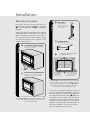
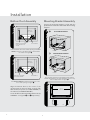
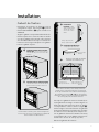
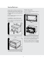
Installation
Mounting Template
Determine which mounting method to use
based on the required configuration. See figure
2A for FLUSH MOUNT and 2B for SURFACE
MOUNT.
Align the template corresponding to the required
mounting method to the center of the cabinet.
Make sure that the template is level with the
floor. Tape it into place. Cut the cabinet opening
along the lines specified on the template. Leave
template taped in place.
For SURFACE MOUNT, predrill 4 holes marked “A” with a
1/16" drill bit. Remove template from the cabinet. Go to
Bottom Duct Assembly.
2
figure
A
FLUSH MOUNT CONFIGURATION—
Microwave Oven and Frame Assembly glass
are flush with the cabinet.
B
SURFACE MOUNT CONFIGURATION
—Microwave Oven and Frame Assembly
protrude from the surface of the cabinet.
b. Surface Mount Configuration -
Microwave Oven and Frame Assembly
protrude from the surface of the cabinet.
Illustration 2
a. Flush Mount Configuration -
Microwave Oven and Frame Assembly
glass are flush with the cabinet
Indicated surfaces are flush.

6
E
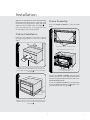
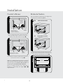
Installation
Bottom Duct Assembly
4
figure
CENTER THE
BOTTOM DUCT
Illustration 6 - for Flush Mount
SCREW A
BOTTOM DUCT
MAKE BOTTOM FLANGE
FLUSH WITH BOTTOM
SPACER
Place the Bottom Duct in the cabinet opening. For FLUSH
MOUNT, it will rest on the bottom spacer centered with
the cabinet. See figure 4.
5
figure
Illustration 7 - for Surface Mount
CENTER THE
BOTTOM DUCT
SCREW A
BOTTOM DUCT
MAKE BOTTOM FLANGE
FLUSH WITH CABINET
For SURFACE MOUNT, the Bottom Duct will rest on the
floor of the opening. See figure 5.
Align the Bottom Duct to the center of the
opening with the bottom flange securely flush
with the bottom spacer (for FLUSH MOUNT) or
the cabinet (for SURFACE MOUNT).
Secure the Bottom Duct Assembly with the two (2)
SCREWS A. See figures 4 and 5 respectively.
Mounting Bracket Assembly
Position the mounting brackets to align with the
predrilled holes that were drilled with the mounting
template.
SCREW B
SCREW B
A
B
FLUSH MOUNT BRACKET
figure
figure
6
SURFACE MOUNT BRACKET
The enclosed ends of the mounting brackets should face
inwards. Check that they are vertical and then secure loosely
with four (4) Screws B. See figure 6.
figure
figure
7
27-1/2"
(698.5mm)
EQ. EQ.

7
E
Installation
Align the mounting brackets horizontally by sliding
them back and forth along the screw slots until
the brackets are exactly 27-1/2" apart and equal
distance from the cabinet sides. See figure 7.
Once the brackets are correctly positioned,
securely tighten the four (4) screws B.
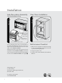
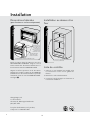
Cabinet Installation
Place the oven adjacent to the wall or cabinet
opening. Plug the power cord into the electrical
outlet.
CABINET INSTALL FRAME INSTALL CABINET INSTALL
figure
figure
8
Carefully guide the assembled oven into the prepared
opening. Slide the oven onto the Bottom Duct Assembly.
See figure 8.
figure
figure
9
CABINET INSTALL FRAME INSTALL CABINET INSTALL
BOTTOM
DUCT
ASSEMBLY
FOOT
DUCT RECESS
Avoid pinching the cord between the oven and the wall.
Adjust the position of the oven so that the feet of the oven
are fitted into the recesses of the Bottom Duct Assembly.
S
ee figure 9.
Frame Assembly
Turn over FRAME ASSEMBLY to locate the 4 ball
studs.
Position the FRAME ASSEMBLY with the small
stainless decorations on top. Align the 4 ball studs
with the 4 snap attachments at both ends of the
MOUNTING BRACKETS.
Secure the FRAME ASSEMBLY by firmly pushing
it onto the Mounting Brackets engaging the four
(4) snap attachments. See figure !.
figure
figure
!
SNAP ATTACHMENT LOCATIONS ON
MOUNTING BRACKETS
SMALL STAINLESS DECORATIONS ON TOP
4 BALL STUDS ON BACK OF FRAME ASSEMBLY

Viking Range, LLC
111 Front Street
Greenwood, Mississippi 38930 USA
(662) 455-1200
For product information
call 1-888-845-4641
8
E
Over Oven Installation
figure
figure
#
2" (5.1 CM) FOR 30" W LOWER OVEN
Performance Checklist
1. Make sure the unit has been installed according
to all of the Installation Instructions and the
required Mounting Template.
2. Plug in the power cord.
3. Keep the Use & Care Manual and Installation
Manual.
Installation
Side Decoration Assembly
(For Surface Mount Only)
Peel the backing off the tape on the backside of
the SIDE DECORATIONS. Align the front inner
edge of the side decorations to the front side
edge of the FRAME ASSEMBLY.
Align the top surface of the side decorations to the
top surface of the FRAME ASSEMBLY. Secure the
side decorations by pressing them firmly against
the side of the FRAME ASSEMBLY. See figure ".
"
figure
ALIGN TOP
SURFACE OF SIDE
DECORATION TO
TOP SURFACE OF
FRAME ASSEMBLY
FRONT INNER EDGE
OF SIDE DECORATION
FRONT SIDE EDGE OF FRAME ASSEMBLY

Guide d’installation
Kit de garniture à encastrer pour
four à micro-ondes

F
10
Table des matières
IMPORTANT–
Prière de lire et d’observer!
Avertissements et Information importante ————————————————————— 10
Spécifications ————————————————————————————————— 11
Information générale
Pièces comprises dans le kit ——————————————————————— 12
Découpe de l’armoire ou du mur ————————————————————— 12
Emplacement de la prise électrique ———————————————————— 12
Installation —————————————————————————————————— 13
Gabarit de fixation ———————————————————————————— 13
Pose du conduit inférieur ————————————————————————— 14
Brides de fixation ———————————————————————————— 14
Installation dans l’armoire ————————————————————————— 15
Cadre de porte ————————————————————————————— 15
Décorations latérales (pour fixation en surface uniquement) —————————— 16
Installation au dessus d’un four —————————————————————— 16
Liste de contrôle du rendement ————————————————————————— 16
• Prière de lire attentivement toutes ces
directives avant de commencer.
• Veiller à DÉBRANCHER LA FICHE du four
à micro-ondes de la prise électrique avant
d’installer la garniture à encastrer. Retirer la
table tournante de la cavité du four.
• Le kit comprend des parties métalliques, il
faut faire attention lors de la manipulation
et de l’installation pour éviter éventuelles
blessures.
• Ne pas retirer de façon permanente les
étiquettes, les mises en garde ou les plaques
fixées au produit. Cela pourrait annuler la
garantie.
• Veuillez observer tous les codes et règlements
locaux et nationaux.
• L’installateur devra laisser ces directives au
client qui devra les conserver pour l’usage
d’un inspecteur local et pour référence
ultérieure.
AVERTISSEMENT
Ce kit à encastrer est conçu pour être utilisé
uniquement avec les fours à micro-ondes
spécifiant kit à encastrer RDMTK302 sur
l’étiquette des spécifications nominales sur la
paroi gauche de la cavité du four.

F
11
Specifications
Four à micro-ondes
Kit de garniture à
encastrer
RVM320 / CRVM320 RVMTK330
Largeur hors tout 24 po (609 mm) 29-1/2 po (749 mm)
Hauteur hors tout depuis le bas 13-3/8 po (339 mm) 17-1/4 po (437 mm)
Profondeur hors tout depuis l’arrière 19-1/8 po (487 mm) S/O
Intérieur du four Largeur
Hauteur
Profondeur
Hors tout
17-3/8 po
10-1/2 po
18-5/8 po
2 pi3
(441 mm)
(266 mm)
(473 mm)
(0,04 m3)
S/O
Alimentation électrique 120VAC/60 Hz S/O
Max. Ampèrage max. 1,5 KW 13 amps S/O
Poids approx. à l’expédition. 46 lb. (20,9 kg) 15 lb. (6,9 kg)
En conformité avec les normes établies par :
FCC – Autorisé par la Federal Communications Commission.
DHHS – Conforme au règlement du Department of Health and Human Services (DHHS), CFR, Titre
21, Chapitre I, Souschapitre J.
– Ce symbole sur l’étiquette des spécifications nominales signifie que le produit est sur la liste
des Underwriters Laboratories, Inc. pour une utilisation aux É.-U. ou au Canada.

F
12
Information générale
14-1/4" (361.95 mm)
Minimum Cutout Opening Width 27-3/4" (704.9 mm)
Minimum Cutout Opening Height 16-9/16" (420.7 mm)
Maximum Cutout Opening Height 16-13/16" (427 mm)
Maximum Cutout Opening Width 28" (711.2 mm)
Distance between holes A9.1" (231.2 mm)
14" (355.6 mm)
Center Line
Floor Line of Cutout Opening
BUILT-IN TRIM KIT
SURFACE MOUNTING TEMPLATE
FOR DESIGNER SERIES MICROWAVE OVEN
TINSKB180MRR0
1/4"
(6.2 mm)
1/4"
(6.2 mm)
1. Align the Surface Mounting Template center line with the
center of the cabinet. Align the Floor Line with the bottom
of the cabinet at the desired height. Tape it into place.
2. Predrill 4 holes marked A with a ¹₁₆" drill bit.
3. Cut the cabinet opening between the minimum and
maximum cutout opening lines. Be careful to cut precisely
along the Floor Line of the cutout.
4. Remove template from the cabinet.
3-15/16" (100 mm)
7
2
1) Frame Assembly: QTY 1 2) Bottom Duct Assembly: QTY 1
3) Mouting Bracket: QTY 2 4) SIDE DECORATION: QTY 2
(SURFACE MOUNTING ONLY)
3
1) Frame Assembly: QTY 1 2) Bottom Duct Assembly: QTY 1
3) Mouting Bracket: QTY 2 4) SIDE DECORATION: QTY 2
(SURFACE MOUNTING ONLY)
6
1) Frame Assembly: QTY 1 2) Bottom Duct Assembly: QTY 1
3) Mouting Bracket: QTY 2 4) SIDE DECORATION: QTY 2
(SURFACE MOUNTING ONLY)
1
1) Frame Assembly: QTY 1 2) Bottom Duct Assembly: QTY 1
3) Mouting Bracket: QTY 2 4) SIDE DECORATION: QTY 2
(SURFACE MOUNTING ONLY)
4
5
4-3/16" (106.4 mm)
FLOOR LINE OF CUTOUT OPENING
BUILT-IN TRIM KIT
FLUSH MOUNTING TEMPLATE
FOR DESIGNER SERIES MICROWAVE OVEN
CABINET CUTOUT LINE
CABINET CUTOUT LINE
CENTER LINE
TINSKB181MRR0
1. Align the Flush Mounting Template center line with the center of the
cabinet. Align the Floor Line with the bottom of the cabinet at the
desired height. Tape it in place.
2. Cut the cabinet opening along the three Cabinet Cutout Lines and
the Floor Line.
3. Install two Side Spacers (see FIGURE 1) and one Bottom Spacer (see
FIGURE 2) as specified in FIGURE 3. Be sure to offset all three spacers
by 1⁹₁₆" from the front surface of the cabinet.
4. Cut out the Side Spacer Templates (R and L) and align the indicated
edge to the corresponding Side Spacer (see FIGURE 3). Be careful to
align the Floor Line to the bottom edges of the Side Spacers.
5. Predrill two holes indicated “A“ in Side Spacer - R with a ¹₁₆" drill bit.
6. Predrill two holes indicated ”B“ in Side Spacer - L with a ¹₁₆" drill bit.
7. Remove template from the cabinet.
SIDE SPACER TEMPLATE - L
SIDE SPACER TEMPLATE - R
FIGURE 1
Side Spacer (2 required)
Must protrude from edge of cabinet
cutout towards center as shown.
Align Side Spacer-L to this line
Align Side Spacer-R to this line
Cutout Opening Height 17-5/16" (439.8 mm)
CABINET CUTOUT LINE
Edges to align Side Spacer Templates (R and L)
Bottom Spacer centered with cabinet cutout
1-9/16" (39.7 mm)
Bottom and Side
Spacer (R and L) Offset
FIGURE 3
Side Spacer - L Side Spacer - R
14" (355.9 mm)
Distance between holes A9.1" (231.2 mm)
Cutout Opening Width 29-5/8" (752.5 mm)
14-13/16" (376.2 mm)
13/16" Min.
15/16 Max.
13-1/2" min. height
FIGURE 2
Bottom Spacer (1 required) ¹₄" plywood
24" min. width
27-7/8" max. width
1/4" (6.35 mm)1/4" (6.35 mm)
8
Pièces comprises dans le kit
Numéro Nom de pièce Qté
1
Cadre de porte 1
2
Conduit inférieur 1
3
Bride de fixation 2
4
Vis A : longueur 1-3/16 po (30,2 mm) 2
5
Vis B : longueur 1 3/4 po (44,5 mm) 4
6
Décorations latérales (pour fixation
en surface uniquement)
2
7
Gabarit de fixation en surface 1
8
Gabarit de fixation encastrée 1
Emplacement de la prise
électrique
MISE EN GARDE
La prise NE doit PAS se trouver dans l’aire
ombrée comme indiqué à l’Illustration 1.
1
figure
4 po (102 mm)
4 po (102 mm)
6 po (15,2 mm)
NOTES :
• Silaprofondeur(C)dépasse53,3cm(21po),
l’emplacement de laprise peut être situé
n’importeoùsurlemurarrière.
• Leplancher de l’ouverturedoit être en
contreplaquéassezfortpoursupporterlepoids
dufouretsaproprecharge(environ45,5kg
[100lb]).Ildoitêtreàun niveauconvenable
pourl’utilisationdu four.Veillerà vérierle
codelocaldubâtiment,carilpourraitexiger
que l’ouverturesoitfermée par une cloison
latérale,arrièreetunplafond.Lefourn’apas
besoind’êtreenclospourfonctionner.
Découpe de l’armoire ou
du mur
Dimensions de la
découpe
Fixation
encastrée
Fixation en
surface
Hauteur A
Minimum
17-5/16 po
(439,8 mm)
16-9/16 po
(420,7 mm)
Maximum
N/A 16-13 / 16 p o
(427 mm)
Largeur B
Minimum
29-5/8 po
(752,5 mm)
27-3/4 po
(704,9 mm)
Maximum
N/A 28 po
(711,2 mm)
Profondeur C
Minimum
20po
(503mm)
20po
(503mm)

F
13
Installation
13/16" min.
15/16" max.
13-1/2" min.
24" min. width
27-7/8" max. width
1-9/16" (39.7 mm)
BOTTOM and SIDE
SPACER (R and L) offset
EDGES TO ALIGN SIDE SPACER
TEMPLATES (R and L)
Side Spacer (L) Side Spacer (R)
BOTTOM SPACER
CENTERED with
CABINET CUTOUT
3
figure
A
ENTRETOISE
LATÉRALE—2. Doit
dépasser du bord de la
découpe de l’armoire
vers le centre comme
illustré.
B
ENTRETOISE INFÉRIEURE—1.
Contreplaqué 1/4 po (6,35 mm)
C
Pour la fixation encastrée, il faut deux (2) entretoises
latérales et une (1) entretoise inférieure. Les entretoises
ne sont pas fournies dans le kit et doivent être fabriquées
par l’installateur. Voir figures 3A et B pour les exigences
d'entretoise. Veiller à ce que les trois entretoises dépassent
de 1-9/16 po (39,7 mm) à l'avant de l'armoire.
Découper les gabarits d’entretoise latérale (D et
G) du gabarit de montage encastré. Aligner les
bords indiqués aux entretoises droite et gauche
correspondantes comme l’illustre la figure 3.
Veiller à aligner les bords inférieurs des gabarits
d'entretoise latérale avec le plancher de l'ouverture
de l'armoire. Percer deux (2) trous marqués « A »
sur un gabarit D d'entretoise latérale et deux (2)
trous marqués « B » sur un gabarit G d'entretoise
latérale avec un foret de 1/16 po (1,6 mm).
Enlever les gabarits de l'armoire.
13-1/2 po
(342,9 mm)
min
13/16 po (20,6 mm) min
15/16 po (23,8 mm) max
Largeur min 24 po
(609 mm)
Largeur max 27-7/8 po
(708 mm)
1-9/16 po (39,7 mm)
Déport d’entretoises
Inférieure et Latérales
(D et G)
Entretoise inférieure
Centrée avec la
Découpe de l’armoire
BORDS POUR ALIGNER LES GABARITS
D’ENTRETOISE LATÉRALE (D et G)
Entretoise
Latérale (G)
Entretoise
Latérale (D)
Installation
Gabarit de fixation
Déterminer la méthode de fixation selon la
configuration requise. Voir la figure 2A pour la
fixation ENCASTRÉE et 2B pour la fixation en
SURFACE.
Aligner le gabarit correspondant à la méthode de
fixation requise avec le centre de l'armoire. Veiller
à ce que le gabarit soit horizontal. Coller en place
avec du ruban adhésif. Découper l'ouverture de
l'armoire selon les lignes indiquées sur le gabarit.
Laisser le gabarit en place.
Pour la fixation en surface, percer 4 trous marqués « A »
avec un foret de 1/16 po (1,6 mm). Enlever le gabarit de
l’armoire Aller au conduit inférieur.
2
figure
A
CONFIGURATION POUR FIXATION
ENCASTRÉE—Le four à microondes et le
verre du cadre de porte sont encastrés dans
l’armoire.
B
SURFACE MOUNT CONFIGURATION
—Le four à microondes et le verre du cadre de
porte font saillie de la surface de l’armoire.
b. Surface Mount Configuration -
Microwave Oven and Frame Assembly
protrude from the surface of the cabinet.
Illustration 2
a. Flush Mount Configuration -
Microwave Oven and Frame Assembly
glass are flush with the cabinet
Les surfaces indiquées affleurent.

F
14
Installation
Conduit inférieur
4
figure
CENTER THE
BOTTOM DUCT
Illustration 6 - for Flush Mount
VIS A
CONDUIT
INFÉRIEUR
FAIRE AFFLEURER LA
BRIDE INFÉRIEURE AVEC
L'ENTRETOISE INFÉRIEURE
Placer le conduit inférieur dans l’ouverture de l’armoire.
Pour le montage encastré, il reposera sur l’entretoise
inférieure centrée dans l’armoire. Voir figure 4.
5
figure
Illustration 7 - for Surface Mount
CENTER THE
BOTTOM DUCT
VIS A
CONDUIT
INFÉRIEUR
FAIRE AFFLEURER LA BRIDE
INFÉRIEURE AVEC L’ARMOIRE
Pour la fixation en surface,le conduit inférieur reposera sur
le plancher de l’ouverture. Voir figure 5.
Aligner le conduit inférieur au centre de l’ouverture
avec la bride inférieure affleurant l’entretoise
inférieure (pour la FIXATION ENCASTRÉE) ou
l’armoire (pour la FIXATION EN SURFACE).
Fixer le conduit inférieur avec deux VIS A
(2-3/16 po [ 55,6 mm]). Voir figures 4 et 5
respectivement.
Brides de fixation
Placer les brides de fixation pour les aligner avec
les trous percés à l’aide du gabarit.
VIS B
VIS B
A
B
BRIDE FIXÉE ENCASTRÉE
figure
figure
6
BRIDE FIXÉE EN SURFACE
Les extrémités encastrées des brides de fixation doivent
faire face à l’intérieur. Vérifier qu’elles sont verticales et les
fixer à demi avec quatre (4) VIS B. Voir figure 6.
figure
figure
7
27-1/2 po
(698,5 mm)
EQ. EQ.
CENTRER LE
CONDUIT
INFÉRIEUR
CENTRER LE
CONDUIT IN-
FÉRIEUR

F
15
Installation
Aligner les brides de fixation horizontalement en
les faisant glisser vers l'avant et l'arrière le long
des fentes de vis jusqu'à ce que les brides soient
exactement séparées de 27-1/2 po (698,5 mm)
et à égale distance des côtés de l'armoire. Voir
figure 7.
Une fois les brides correctement placées, bien les
fixer avec quatre (4) vis B.
Installation dans l'armoire
Placer le four près de l'ouverture du mur ou de
l'armoire. Brancher le cordon d'alimentation dans
la prise électrique.
CABINET INSTALL FRAME INSTALL CABINET INSTALL
figure
figure
8
Guider avec précaution le four assemblé dans l'ouverture
préparée. Faire glisser le four sur le conduit inférieur. Voir
figure 8.
figure
figure
9
CABINET INSTALL FRAME INSTALL CABINET INSTALL
CONDUIT
INFÉRIEUR
PATTE
ÉVIDEMENT DANS
LE CONDUIT
Éviter de pincer le cordon entre le four et le mur. Ajuster la
position du four de façon à ce que ses pattes entrent dans
les évidements du conduit d'évacuation. Voir figure
9
.
Cadre de porte
Retourner le CADRE DE PORTE pour repérer les
quatre pivots à rotule.
Placer le cadre de porte avec les petites décorations
en acier inox sur le dessus. Aligner les quatre
pivots à rotule avec les fixations à pression aux
deux extrémités des BRIDES DE FIXATION.
Bien fixer le cadre de porte en le poussant
fermement sur les brides de fixation en engageant
les quatre (4) fixations à pression. Voir figure !.
figure
figure
!
EMPLACEMENT DES FIXATIONS À PRESSION
SUR LES BRIDES DE FIXATION
PETITES DÉCORATIONS EN ACIER INOX SUR LE DESSUS
QUATRE PIVOT À ROTULE À L’ARRIÈRE DU CADRE DE PORTE

F
16
Installation
F
Installation
Viking Range, LLC
111 Front Street
Greenwood, Mississippi 38930 USA
(662) 455-1200
Pour plus d'information sur le produit,
Composer le 1-888-845-4641
Installation au dessus d'un
four
figure
figure
#
5,1 CM (2 po) POUR UN FOUR INFÉRIEUR DE
91,4 CM (30 po) DE LARGE
Liste de contrôle
1. Veiller à ce que l'appareil soit installé selon
les instructions et avec le bon gabarit de
fixation.
2. Brancher le cordon d'alimentation.
3. Conserver le mode d'emploi et d'entretien et
le manuel d'installation
Décorations latérales
(pour fixation en surface uniquement)
Retirer le papier dorsal du ruban au verso des
DÉCORATIONS LATÉRALES. Aligner le bord
intérieur avant des décorations latérales avec le
bord intérieur avant du CADRE DE PORTE.
Aligner la surface supérieure de la décoration
latérale avec la surface supérieure du CADRE DE
PORTE. Fixer les décorations latérales en pressant
fermement contre le côté du CADRE DE PORTE.
Voir figure ".
"
figure
ALIGNER LA SUR-
FACE SUPÉRIEURE
DE LA DÉCORA-
TION LATÉRALE
AVEC LA SURFACE
SUPÉRIEURE DU
CADRE DE PORTE
BORD INTÉRIEUR
AVANT DE LA DÉC-
ORATION LATÉRALE
BORD INTÉRIEUR AVANT DU CADRE DE PORTE

Guía de instalación
Juego de molduras para empotrado
del Microondas
S

S
18
S
18
Tabla de Contenido
IMPORTANTE–
¡Lea y siga con atención!
Advertencias e información importante —————————————————————— 18
Especificaciones ———————————————————————————————— 19
Información general ——————————————————————————————— 20
Partes incluidas en el juego ———————————————————————— 20
Abertura del gabinete o pared —————————————————————— 20
Ubicación del tomacorriente eléctrico ——————————————————— 20
Instalación ——————————————————————————————————— 21
Plantilla de montaje ——————————————————————————— 21
Conjunto de ducto inferior ———————————————————————— 21
Ensamblaje del soporte de montaje ———————————————————— 22
Instalación en gabinete —————————————————————————— 23
Instalación del marco —————————————————————————— 23
Instalación de la decoración lateral ———————————————————— 24
Instalación de la decoración lateral ———————————————————— 24
Lista de control de ejecución ——————————————————————————— 24
• Antes de comenzar, lea estas instrucciones
completa y detalladamente.
• Asegúrese de DESCONECTAR el horno
microondas del tomacorriente eléctrico
antes de instalar el juego de moldura para
empotrado. Retire el plato giratorio de la
cavidad del horno.
• El juego incluye partes de metal por lo que
debe manipularlo e instalarlo con precaución
para evitar el riesgo de lesiones.
• No retire las etiquetas, advertencias o placas
permanentes del producto. Esto puede anular
la garantía.
• Cumpla todos los códigos y normas locales
y nacionales.
• El instalador debe devolver estas instrucciones
al cliente quien debe conservarlas para uso
del inspector local y para referencias futuras.
ADVERTENCIA
Este juego de molduras para empotrado
está diseñado para uso exclusivo con hornos
microondas que especifique el juego de
molduras para empotrado RDMTK302 en la
etiqueta de potencia en la cavidad del horno.

S
19
Especificaciones
Horno microondas
Juego de molduras
para empotrado
RVM320 / CRVM320 RVMTK330
Ancho total 24" (60.9 cm) 29-1/2" (74.9 cm)
Altura total desde la parte
inferior
13-3/8" (33.9 cm) 17-1/4" (43.7 cm)
Profundidad total desde la
parte posterior
19-1/8" (48.7 cm) NA
Parte interna del horno Ancho
Altura
Profundidad
Ancho total
17-3/8"
10-1/2"
18-5/8"
2.0 pies
cúbicos
(44.1 cm)
(26.6 cm)
(47.3 c m)
NA
Requisitos eléctricos 120VCA/60 Hz NA
Cap. máx. en amperios 1.5 KW 13 amps NA
Peso de despacho aprox. 46 lbs. (20.9 kg) 15 lbs. (6.9 kg)
Cumple con las normas establecidas por:
FCC – Autorizada por la Comisión Federal de Comunicaciones.
DHHS – Cumple con la norma del Departamento de Salud y Servicios Humanos (DHHS), CFR,
Título 21, capítulo I, subcapítulo J.
– Este símbolo en la etiqueta de potencia indica que el producto está aprobado por
Underwriters Laboratories, Inc. para uso en los EE.UU. o Canadá.

S
20
S
20
Información general
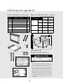
2
1) Frame Assembly: QTY 1 2) Bottom Duct Assembly: QTY 1
3) Mouting Bracket: QTY 2 4) SIDE DECORATION: QTY 2
(SURFACE MOUNTING ONLY)
3
1) Frame Assembly: QTY 1 2) Bottom Duct Assembly: QTY 1
3) Mouting Bracket: QTY 2 4) SIDE DECORATION: QTY 2
(SURFACE MOUNTING ONLY)
6
1) Frame Assembly: QTY 1 2) Bottom Duct Assembly: QTY 1
3) Mouting Bracket: QTY 2 4) SIDE DECORATION: QTY 2
(SURFACE MOUNTING ONLY)
1
1) Frame Assembly: QTY 1 2) Bottom Duct Assembly: QTY 1
3) Mouting Bracket: QTY 2 4) SIDE DECORATION: QTY 2
(SURFACE MOUNTING ONLY)
4
5
14-1/4" (361.95 mm)
Minimum Cutout Opening Width 27-3/4" (704.9 mm)
Minimum Cutout Opening Height 16-9/16" (420.7 mm)
Maximum Cutout Opening Height 16-13/16" (427 mm)
Maximum Cutout Opening Width 28" (711.2 mm)
Distance between holes A9.1" (231.2 mm)
14" (355.6 mm)
Center Line
Floor Line of Cutout Opening
BUILT-IN TRIM KIT
SURFACE MOUNTING TEMPLATE
FOR DESIGNER SERIES MICROWAVE OVEN
TINSKB180MRR0
1/4"
(6.2 mm)
1/4"
(6.2 mm)
1. Align the Surface Mounting Template center line with the
center of the cabinet. Align the Floor Line with the bottom
of the cabinet at the desired height. Tape it into place.
2. Predrill 4 holes marked A with a ¹₁₆" drill bit.
3. Cut the cabinet opening between the minimum and
maximum cutout opening lines. Be careful to cut precisely
along the Floor Line of the cutout.
4. Remove template from the cabinet.
3-15/16" (100 mm)
7
4-3/16" (106.4 mm)
FLOOR LINE OF CUTOUT OPENING
BUILT-IN TRIM KIT
FLUSH MOUNTING TEMPLATE
FOR DESIGNER SERIES MICROWAVE OVEN
CABINET CUTOUT LINE
CABINET CUTOUT LINE
CENTER LINE
TINSKB181MRR0
1. Align the Flush Mounting Template center line with the center of the
cabinet. Align the Floor Line with the bottom of the cabinet at the
desired height. Tape it in place.
2. Cut the cabinet opening along the three Cabinet Cutout Lines and
the Floor Line.
3. Install two Side Spacers (see FIGURE 1) and one Bottom Spacer (see
FIGURE 2) as specified in FIGURE 3. Be sure to offset all three spacers
by 1⁹₁₆" from the front surface of the cabinet.
4. Cut out the Side Spacer Templates (R and L) and align the indicated
edge to the corresponding Side Spacer (see FIGURE 3). Be careful to
align the Floor Line to the bottom edges of the Side Spacers.
5. Predrill two holes indicated “A“ in Side Spacer - R with a ¹₁₆" drill bit.
6. Predrill two holes indicated ”B“ in Side Spacer - L with a ¹₁₆" drill bit.
7. Remove template from the cabinet.
SIDE SPACER TEMPLATE - L
SIDE SPACER TEMPLATE - R
FIGURE 1
Side Spacer (2 required)
Must protrude from edge of cabinet
cutout towards center as shown.
Align Side Spacer-L to this line
Align Side Spacer-R to this line
Cutout Opening Height 17-5/16" (439.8 mm)
CABINET CUTOUT LINE
Edges to align Side Spacer Templates (R and L)
Bottom Spacer centered with cabinet cutout
1-9/16" (39.7 mm)
Bottom and Side
Spacer (R and L) Offset
FIGURE 3
Side Spacer - L Side Spacer - R
14" (355.9 mm)
Distance between holes A9.1" (231.2 mm)
Cutout Opening Width 29-5/8" (752.5 mm)
14-13/16" (376.2 mm)
13/16" Min.
15/16 Max.
13-1/2" min. height
FIGURE 2
Bottom Spacer (1 required) ¹₄" plywood
24" min. width
27-7/8" max. width
1/4" (6.35 mm)1/4" (6.35 mm)
8
Partes incluidas en el juego
Artículo
Nombre de la parte
CANT.
1
Conjunto del marco 1
2
Conjunto del ducto inferior 1
3
Soporte de montaje 2
4
Tornillo A :1-3/16” de largo 2
5
Tornillo B: 1-3/4” de largo 4
6
Decoración lateral (Sólo superficie
de montaje)
2
7
Plantilla para montaje en superficie 1
8
Plantilla para montaje al ras 1
Ubicación del
tomacorriente eléctrico
PRECAUCIÓN
El tomacorriente NO debe estar en el área
sombreada como se indica en la figura 1.
1
figura
4"(10.2 cm)
4"(10.2 cm)
6"(15.2 cm)
NOTAS:
• Siladimensióndeprofundidad(C)esmayora21”
(53.3 cm), laubicación del tomacorrientepuede
estarencualquieráreadelaparedposterior.
• El piso de laabertura debe estar construido de
maderalaminadalosucientementeresistentepara
soportarelpesodelhornoylacapacidaddecarga
(aproximadamente100libras).Elpisodebeestar
nivelado para una correcta operación del horno.
Asegúresedevericarel códigodeconstrucción
local ya que puede requerir cercar la abertura
con tabiques laterales, superior y posterior. El
funcionamientoapropiadodelhornonorequiere
delcercado.
Abertura del gabinete o pared
Dimensiones de
recorte
Brindas
Montaje
Superficie
Montaje
Altura A
Mínimo
17-5/16"
(439.8mm)
16-9/16"
(420.7mm)
Máximo
N/A 16-13/16"
(427mm)
Ancho B
Mínimo
29-5/8"
(752.5mm)
27-3/4"
(704.9mm)
Máximo
N/A 28"
(711.2mm)
Profundidad C
Mínimo
20"
(503mm)
20"
(503mm)

S
21
Instalación
13/16" min.
15/16" max.
13-1/2" min.
24" min. width
27-7/8" max. width
1-9/16" (39.7 mm)
BOTTOM and SIDE
SPACER (R and L) offset
EDGES TO ALIGN SIDE SPACER
TEMPLATES (R and L)
Side Spacer (L) Side Spacer (R)
BOTTOM SPACER
CENTERED with
CABINET CUTOUT
3
figura
A
SPACER LADO—2
NECESARIO. Debe
sobresalir del borde de
corte hacia el centro
del gabinete como se
muestra.
B
FONDO SPACER—1 SOLICITAN.
1 / 4 "de madera contrachapada.
C
Para MONTAJE AL RAS, instale dos (2) espaciadores laterales
y un (1) espaciador inferior como se muestra en la figura 3 A y
B. Los espaciadores no están incluidos en el juego y deben ser
fabricados por el instalador. Los requisitos para el espaciador
se indican en la Plantilla para montaje al ras. Asegúrese que los
tres espaciadores estén equilibrados desde la parte frontal del
gabinete por 1-9/16".
Recorte las plantillas del espaciador lateral (R y
L) de las plantillas de montaje al ras. Alinee los
bordes indicados con los espaciadores izquierdo
y derecho correspondientes como se muestra
en la figura 3. Asegúrese de alinear los bordes
inferiores de las plantillas de los espaciadores
laterales a la base de la abertura del gabinete. Pre-
taladre (2) agujeros marcados “A” en la plantilla
del espaciador lateral – R y dos (2) agujeros
marcados “B” en la plantilla del espaciador lateral
– L con una broca 1/16".
Retire las plantillas del gabinete.
Espaciador inferior
centrado con el
recorte del gabinete
1-9/16" (39.7 mm)
Compensación para
espaciador lateral e
inferior (R y L)
Espaciador
lateral - R
Espaciador
lateral - L
BORDES PARA ALINEA
LAS PLANTILLAS DE LOS
ESPACIADORES LATERALES (R Y L)
24" min. anchura
27-7/8" máx. anchura
13/16" min.
15/16" máx.
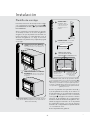
Plantilla de montaje
Determine el método de montaje a usar en base
a la configuración requerida. Vea la figura 2A
para MONTAJE AL RAS y 2B para MONTAJE
EN SUPERFICIE.
Alinee la plantilla correspondiente al método
de montaje necesario en el centro del gabinete.
Asegúrese de que la plantilla esté nivelada con
la base. Asegúrelo con cinta adhesiva. Corte la
abertura del gabinete a lo largo de las líneas
señaladas en la plantilla. Deje la plantilla pegada
en el lugar.
For SURFACE MOUNT, predrill 4 holes marked “A” with a
1/16" drill bit. Remove template from the cabinet. Go to
Bottom Duct Assembly.
2
figura
A
CONFIGURACIÓN PARA MONTAJE
AL RAS — El horno microondas y el vidrio
del conjunto del marco están alineados con
el gabinete.
b. Surface Mount Configuration -
Microwave Oven and Frame Assembly
protrude from the surface of the cabinet.
Illustration 2
a. Flush Mount Configuration -
Microwave Oven and Frame Assembly
glass are flush with the cabinet
Las superficies indicadas están alineadas.
B
CONFIGURACIÓN DE LA SUPERFICIE
DE MONTAJE — El horno microondas y el
conjunto del marco sobresalen de la superficie
del gabinete.

S
22
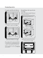
Conjunto del Ducto Inferior
4
figura
CENTER THE
BOTTOM DUCT
Illustration 6 - for Flush Mount
TORNILLO A
CONJUNTO DEL
DUCTO INFERIOR
COLOQUE LA BRIDA INFERIOR AL
RAS CON EL GABINETE
Coloque el Ducto inferior en la abertura del gabinete. Para
MONTAJE AL RAS, se apoyará en el espaciador inferior
centrado con el gabinete. Vea la figura 4.
5
figura
Illustration 7 - for Surface Mount
CENTER THE
BOTTOM DUCT
TORNILLO A
CONJUNTO DEL
DUCTO INFERIOR
COLOQUE LA BRIDA INFERIOR AL RAS
CON EL GABINETE
Para MONTAJE EN SUPERFICIE, el ducto inferior se
apoyará en la base de la abertura. Vea la figura 5.
Alinee el ducto inferior al centro de la abertura
con la brida inferior colocada firmemente al ras
con el espaciador inferior (para MONTAJE AL RAS)
o el gabinete (para MONTAJE EN SUPERFICIE).
Asegure el conjunto del ducto inferior con los
dos (2) TORNILLOS A. Vea las figuras 4 y 5
respectivamente.
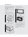
Ensamblaje del soporte de
montaje
Coloque los soportes de montaje para que se
alineen con los agujeros taladrados preparados
con la plantilla de montaje.
TORNILLO B
TORNILLO B
A
B
SOPORTE PARA MONTAJE AL RAS
6
SOPORTES PARA MONTAJE EN
SUPERFICIE
Los extremos cerrados de los soportes de montaje deben
quedar hacia dentro. Verifique que estén en posición
vertical y después asegúrelos de forma suelta con los
cuatro (4) tornillos B. Vea la figura 6.
7
27-1/2"
(698.5mm)
EQ EQ.
figura
figura
CENTRE EL DUCTO
INFERIOR
CENTRE EL
DUCTO INFERIOR
Instalación

S
23
Alinee los soportes de montaje horizontalmente
deslizándolos hacia atrás y hacia adelante a través
de las ranuras de los tornillos hasta que los soportes
tengan una distancia exacta de 27-1/2" entre sí y
una distancia igual desde los lados del gabinete.
Vea la figura
7
.
Una vez que los soportes estén posicionados
correctamente, apriete firmemente los cuatro (4)
tornillos B.
Instalación en gabinete
Coloque el horno al lado de la abertura de la pared
o gabinete. Conecte el cordón de alimentación al
tomacorriente eléctrico.
CABINET INSTALL FRAME INSTALL CABINET INSTALL
8
Guíe con cuidado el horno ensamblado dentro de la
abertura preparada. Deslice el horno sobre el conjunto
del ducto inferior. Vea la figura 8.
9
CABINET INSTALL FRAME INSTALL CABINET INSTALL
CONJUNTO
DE DUCTO
INFERIOR
BASE
CAVIDAD DEL DUCTO
Evite que el cable quede entre el horno y la pared. Ajuste
la posición del horno de modo que las patas del horno
encajen en las ranuras del conjunto del ducto de escape.
Vea la figura
9.
Conjunto del marco
Voltee el CONJUNTO DEL MARCO localice los 4
montantes redondos.
!
figura
CUATRO UBICACIONES DE LOS MONTANTES REDONDOS
EN LA PARTE POSTERIOR DEL CONJUNTO DEL MARCO
UBICACIONES DE LAS MUESCAS A PRESIÓN EN LOS
SOPORTES DE MONTAJE
PEQUEÑAS DECORACIONES INOXIDABLES EN LA PARTE
SUPERIOR
Coloque el CONJUNTO DEL MARCO con las
pequeñas decoraciones inoxidables en la parte
superior. Alinee los cuatro montantes redondos
con los 4 accesorios a presión en ambos extremos
de los SOPORTES DE MONTAJE.
Asegure el CONJUNTO DE MARCO presionando
firmemente sobre los soportes de montaje
colocando los cuatro (4) accesorios a presión.
Vea la figura !.
figurafigura
Instalación

S
24
F20971
TINSKB179MRR0
Viking Range, LLC
111 Front Street
Greenwood, Mississippi 38930 EE.UU.
(662) 455-1200
Para mayor información sobre
productos, llame al 1-888-845-4641
Instalación sobre el horno
#
2" (5.1 CM) PARA HORNO INFERIOR DE
30" DE ANCHO
Lista de control de
ejecución
1. Asegúrese de que la unidad ha sido instalada
de acuerdo con todas las instrucciones de
instalación y la plantilla de montaje necesaria.
2. Enchufe el cable de alimentación.
3. Conserve el Manual de uso y cuidado y el
Manual de instalación
Instalación de la
decoración lateral
(Sólo para montaje en superficie)
Retire la cinta de refuerzo de la parte posterior
de las DECORACIONES LATERALES. Alinee
el borde interior frontal de las decoraciones
laterales al borde lateral frontal del CONJUNTO
DEL MARCO.
Alinee la superficie superior de las decoraciones
laterales a la superficie superior del CONJUNTO
DEL MARCO. Asegure las decoraciones laterales
presionándolas firmemente contra el lado del
CONJUNTO DEL MARCO. Vea la figura ".
figura
"
figura
ALÍNEE LA SUPER-
FICIE SUPERIOR DE
LA DECORACIÓN
LATERAL A LA SU-
PERFICIE SUPERIOR
DEL CONJUNTO
DEL MARCO
BORDE INTERIOR
FRONTAL DE LA
DECORACIÓN LATERAL
BORDE LATERAL FRONTAL DEL CONJUNTO DEL MARCO
Instalación
-
 1
1
-
 2
2
-
 3
3
-
 4
4
-
 5
5
-
 6
6
-
 7
7
-
 8
8
-
 9
9
-
 10
10
-
 11
11
-
 12
12
-
 13
13
-
 14
14
-
 15
15
-
 16
16
-
 17
17
-
 18
18
-
 19
19
-
 20
20
-
 21
21
-
 22
22
-
 23
23
-
 24
24


Viking RVMTK Guía de instalación
- Categoría
- Microondas
- Tipo
- Guía de instalación
- Este manual también es adecuado para
En otros idiomas
- français: Viking RVMTK Guide d'installation
- English: Viking RVMTK Installation guide