
UX-30A / UX-221A / UX-218A / UX-218A-R
User's Manual
Antes de utilizar el equipo, lea la sección
“Precauciones de seguridad” de este manual.
Conserve este manual para futuras consultas.
Before operating the device, please read the
“Safety precautions” section of this manual.
Retain this manual for future reference.
series

CONTENTS
Manual del Usuario / UX series / User’s Manual
6 - 7
8 - 9
INTRODUCTION
LINE DRAWINGS
3
4
5
11
10
17 - 29
31
INSTALLATION AND ACCESSORIES
SPECIFICATIONS
ANNEX II : DASnet cables
CONFIGURATIONS
SAFETY PRECAUTIONS
WARRANTY
DECLARATION OF CONFORMITY
Example with UX-218A
Example with UX-221A
12 - 16AMPLIFIERS
30
ANNEX I : Unbalanced and balanced connections

Precauciones de Seguridad
Safety Precautions
3
Cajas acústicas activas / Self-powered loudspeaker enclosures
UX-221A / UX-218A / UX-218RA / UX-30A
The exclamation point inside an equilateral triangle is intended to
alert the users to the presence of important operating and
maintenance (servicing) instructions in the literature
accompanying the product. Heed all warnings. Follow all
instructions. Keep these instructions.
WARNING: This is a class A product. In a domestic environment
this product may cause radio interferences in which case the
user may be required to take adequate measures.
Use this product only in E1, E2, E3 or E4 environments
according to EN55103-2.
Equipo diseñado para funcionar entre 15ºC y 45ºC con una
humedad relativa máxima del 95%, con un rango de ±10% de la
tensión nominal de alimentación indicada en la etiqueta trasera
(según IEC 60065). Si debe sustituir un fusible preste atención al
tipo y rango.
Working temperature ranges from 15ºC to 45ºC with a relative
humidity of 95%, with ±10% of the rated main voltage value
indicated on the rear label (according to IEC 60065). If a fuse
needs to be replaced, please pay attention to correct type and
ratings.
No instale el aparato cerca de ninguna fuente de calor como
radiadores, estufas u otros aparatos que produzcan calor. Debe
instalarse siempre sin bloquear la libre circulación de aire por las
aletas del radiador.
Do not install near any heat sources such as radiators, heat
registers, stoves or other apparatus that produce heat. The
circulation of air through the heatsink must not be blocked.
No exponga este equipo a la lluvia o humedad. No use este
aparato cerca del agua (piscinas y fuentes, por ejemplo). No
exponga el equipo a salpicaduras ni coloque sobre él objetos
que contengan líquidos, tales como vasos y botellas. Equipo IP-
20.
Do not expose this device to rain or moisture. Do not use this
apparatus near water (for example, swimming pools and
fountains). Do not place any objects containing liquids, such as
bottles or glasses, on the top of the unit. Do not splash liquids
on the unit. IP-20 equipment.
No emplace altavoces en proximidad a equipos sensibles a
campos magnéticos, tales como monitores de televisión o
material magnético de almacenamiento de datos.
Do not place loudspeakers in proximity to devices sensitive to
magnetic fields such as television monitors or data storage
magnetic material.
Este símbolo indica que el presente producto no puede ser
tratado como residuo doméstico normal, sino que debe
entregarse en el correspondiente punto de recogida de equipos
eléctricos y electrónicos.
This symbol on the product indicates that this product should
not be treated as household waste. Instead it shall be handed
over to the appicable collection point for the recycling of
electrical and electronic equipment.
El cableado exterior conectado al equipo requiere de su
instalación por una persona instruida o el uso de cables flexibles
ya preparados.
The outer wiring connected to the device requires installation by
an instructed person or the use of a flexible cable already
prepared.
Si el aparato es conectado permanentemente, la instalación
eléctrica del edificio debe incorporar un interruptor multipolar con
separación de contacto de al menos 3mm en cada polo.
If the apparatus is connected permanently, the electrical system
of the building must incorporate a multipolar switch with a
separation of contact of at least 3mm in each pole.
El colgado del equipo sólo debe realizarse utilizando los herrajes
de colgado recomendados y por personal cualificado. No
cuelgue la caja de las asas.
The appliance should be flown only from the rigging points and
by qualified personnel. Do not suspend the box from the
handles.
Limpie con un paño seco. No use limpiadores con disolventes. Clean only with a dry cloth. Do not use any solvent based
cleaners.
No existen partes ajustables por el usuario en el interior de este
equipo. Cualquier operación de mantenimiento o reparación
debe ser realizada por personal cualificado. Es necesario el
servicio técnico cuando el equipo se haya dañado de alguna
forma, como que haya caído líquido o algún objeto en el interior
del aparato, haya sido expuesto a lluvia o humedad, no funcione
correctamente, haya recibido un golpe o su cable de red esté
dañado.
No user serviceable parts inside. Refer all servicing to qualified
service personnel. Servicing is required when the apparatus has
been damaged in any way, such as power-supply cord or plug is
damaged, liquid has been spilled or objects have fallen into the
apparatus, the apparatus has been exposed to rain or moisture,
does not operate normally or has been dropped.
No emplace el producto sobre un carro, base trípode, soporte o
mesa inestables. La unidad puede caer, causando serias heridas
y dañándose gravemente.
Do not place the product on an unstable platform of any kind.
The unit may fall, causing serious injuries and causing serious
damage.
El signo de exclamación dentro de un triángulo indica la
existencia de importantes instrucciones de operación y
mantenimiento en la documentación que acompaña al producto.
Conserve y lea todas estas instrucciones. Siga las advertencias.
ATENCIÓN: Es un producto clase A, por lo que en entornos
domésticos puede causar radio-interferencias, en cuyo caso el
usuario tendrá que tomar las medidas oportunas.
De acuerdo con EN55103-2, usar el equipo sólo en entornos E1,
E2, E3 ó E4.
Para desconectar el dispositivo debe usar el enchufe.
Desconecte este aparato durante tormentas eléctricas,
terremotos o cuando no se vaya a emplear durante largos
periodos.
To disconnect the device, you should use the mains plug. Unplug
this apparatus during lightning storms, earthquakes or when
unused for long periods of time.
No desconecte la tierra en el conector de alimentación pues es
peligroso e ilegal. Equipo de Clase I. El producto debe ser
conectado a un enchufe con toma de tierra. Sólo use este
equipo con el cable de red de alimentación adecuado para su
país.
El signo del rayo con la punta de flecha, alerta contra la
presencia de voltajes peligrosos no aislados. Para reducir el
riesgo de choque eléctrico, no retire la cubierta.
Do not remove mains connector ground, it is dangerous and
illegal. Class I device. The product must be connected to a
mains socket outlet with protective earth connection. Only use
this equipment with an appropriate mains cord for your country.
The lightning and arrowhead symbol warns about the presence
of uninsulated dangerous voltage. To reduce the risk of electric
shock, do not remove the cover.
series
Manual del Usuario / UX series / User’s Manual

4
Todos nuestros productos están garantizados por un periodo de 24
meses desde la fecha de compra.
Las garantías sólo serán válidas si son por un defecto de
fabricación y en ningún caso por un uso incorrecto del producto.
Las reparaciones en garantía pueden ser realizadas,
exclusivamente, por el fabricante o el servicio de asistencia técnica
autorizado.
Otros cargos como portes y seguros, son a cargo del comprador
en todos los casos.
Para solicitar reparación en garantía es imprescindible que el
producto no haya sido previamente manipulado e incluir una
fotocopia de la factura de compra.
GARANTÍA
All our products are warrantied against any manufacturing defect
for a period of 2 years from date of purchase.
The warranty excludes damage from incorrect use of the product.
All warranty repairs must be exclusively undertaken by the factory
or any of its authorised service centers.
To claim a warranty repair, do not open or intend to repair the
product.
Return the damaged unit, at shippers risk and freight prepaid, to
the nearest service center with a copy of the purchase invoice.
WARRANTY
Manual del Usuario / UX series / User’s Manual

5
DECLARACIÓN DE CONFORMIDAD
DECLARATION OF CONFORMITY
DAS Audio Group, S.L.
C/ Islas Baleares, 24 - 46988 - Pol. Fuente del Jarro - Valencia. España
(Spain).
Declara que y :UX-221A, UX-218A, UX-218RA UX-30A
Declares that and :UX-221A, UX-218A, UX-218RA UX-30A
Y es conforme a las siguientes Normas Armonizadas Europeas:
In accordance with Harmonized European Norms:
l EN 60065:2014.- Audio, video and similar electronic apparatus. Safety
requirements.
l EN 55032:2012.- Electromagnetic compatibility of multimedia equipment.
Emission requirements.
l EN 55103-2:2009.- Electromagnetic compatibility. Product family
standard for audio, video, audio-visual and entertainment lighting control
apparatus for professional use. Part 2:Immunity.
l EN 50581:2012.- Technical documentation for the assessment of
electrical and electronic products with respect to the restriction of
hazardous substances.
Cumple con los objetivos esenciales de las Directivas:
Abide by essential objectives relating Directives:
l de Baja Tensión (Low Voltage Directive) 2014/35/UE
l de Compatibilidad Electromagnética (EMC) 2014/30/UE
l RoHS 2011/65/UE
l RAEE (WEEE) 2012/19/UE
Manual del Usuario / UX series / User’s Manual

INTRODUCTION
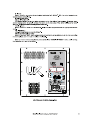
The self-powered UX series is comprised of systems designed in response to demands for high-output
ultra-low frequency solutions. UX-30A, UX-218A and UX-221A are self-powered versions of UX series
models. In addition, UX-218A-R is a version with built-in rigging hardware, and derived model of UX-218A.
The enclosures incorporate front connectors which allow for easy installation when used in cardioid
configurations.
6
Manual del Usuario / UX series / User’s Manual
UX-218A / UX-218A-R
- High performance subwoofer system for external
amplification
- Two 18UXN4 long-excursion loudspeakers (18"
and 4 ohms)
- Front loaded cross-fire configuration
- Solid birch plywood construction
The UX-218A / UX-218A-R join the new range of
UX Series subwoofer systems in self-powered
versions. The UX-218A, or UX-218A-R, make use of
two 18” 18UXN4 transducers. The new
loudspeaker, designed and manufactured by DAS,
offers impressive features such as a 4" sandwich
split winding voice coil, a remarkable 52 mm peak-
to-peak excursion, and a powerful FEA optimized
neodymium magnet assembly. Thanks to the
double silicon spider, the 18UXN4 controls the
moving mass with high linearity. An aluminum
demodulating ring reduces distortion, and effective
ventilation of the voice coil gap provides for a high
thermal rating and reduced power compression.
The enclosure is constructed using Birch
plywood and makes use of extensive bracing to
eliminate resonances. The woodwork is finished
with the robust DAS ISO-flex protective coating
for durability. A dolly platform with locking casters,
PL-UX218S for UX-218A and PL-UX218RS for UX-
218A-R, is available to stack and move the
systems. Protection during transport is provided by
the optional covers available from DAS
UX-218A-R is the flying version with built-in
rigging.
FEATURES
FRONT CONNECTORS FOR
CARDIOID CONFIGURATIONS

7
Manual del Usuario / UX series / User’s Manual
UX-221A
- High power ultra-low frequency subwoofer
system
- Twin 21" Neodymium loudspeakers with 6" voice
coils
- Solid 21 mm birch plywood construction
- Impressive 60 mm peak-to-peak excursion
Th e U X - 2 2 1 A in c lu d e s t w o 2 1 U X N
loudspeakers, 21" and 8 ohms, equipped with 6"
voice coils and offers a power handling capacity of
8000 Wpeak for each loudspeaker. The impressive
60 mm peak-to-peak excursion, powerful
neodymium magnet assembly and double silicone
spider with optimized compliance provide for
commanding low frequency response.
The enclosure is constructed using 21 mm
Birch plywood and makes use of extensive bracing
to eliminate resonances. The woodwork is finished
with the robust DAS ISO-flex protective coating
for durability. A dolly platform with locking casters,
PL-221S, is available to stack and move the
systems. Protection during transport is provided by
the optional covers available from DAS
UX-30A
-Powered subwoofer system
-Single 30" high density polyethylene cone
-Unique moving magnet linear motor design
-Ultra high power amplifier design
-Differential Pressure Control (DPC®)
-Highly reinforced cabinet design
-U nmatc hed per forma nce com pared to
conventional systems
The UX-30A makes use of an innovative and
unique transducer based on the patented M-
Force® moving magnet linear motor structure.
Unparalleled performance in terms of power
handling, electromagnetic conversion, reliability
and maximum SPL are a few of the innovative
features and improvements with respect to the
conventional moving coil arrangement.
The motor system is driven by an ultra high
power Class D amplifier module which is no less
impressive than the motor design. Amazing figures
in terms of both output voltage (310 Vpeak) and
current capabilities (200 Apeak), the M-Drive®
amplifier is capable of exploiting the full potential of
the M-Force®. The DPC® (Differential Pressure
Control) is a powerful active acoustic processing
tool which controls and enhances the performance
of the system.
M-Force®, M-Drive® and DPC® are registered
trademarks of Powersoft S.p.A.
FRONT CONNECTORS FOR
CARDIOID CONFIGURATIONS

CONFIGURATIONS
8
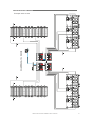
Next, find two examples. You will find more configurations on our website.
Example with UX-218A:
Manual del Usuario / UX series / User’s Manual
24 x AERO-40A + 18 x UX-218A
DASNET-RACK99
DASNET-RACK99

9
Manual del Usuario / UX series / User’s Manual
Example with UX-221A
CONFIGURATIONS (cont’d)
24 x AERO-40A + 12 x UX-221A
DASNET-RACK99
DASNET-RACK99
DASNET-RACK99
DASNET-RACK99


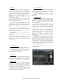
Cardioid Preset
This unique feature facilitates the configuration
of two or three units to create a cardioid response
pattern. This is useful in situations where on-stage
bass level projected from the subs needs to be
kept to a minimum.
To set-up a cardioid configuration with two
stacked units, place the bottom unit facing the
audience and the top box facing the stage. Set the
controls for level, polarity and cut-off frequency
identically on both units. Daisy-chain the signal
from one unit to the other (do not activate the
satellite output high-pass filter). Activate the
Cardioid Preset button on the box facing the
stage. This provides the level and phase
adjustments necessary to cancel the rear
projected sound waves “cleaning” the stage of
unwanted bass.
To assemble a cardioid configuration with three
stacked units, the procedure is basically the same.
Place the lower and top boxes facing the
audience, the middle box facing the stage. Daisy-
chain the signal, make sure the level, polarity and
cut-off frequency are the same on all the boxes
and lastly, activate the Cardioid Preset button on
the box facing the stage.
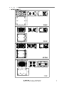
In the next figure, we can view this menu of the
UX-221A units.
14
Manual del Usuario / UX series / User’s Manual
ON / OFF
A sound system should be switched on
sequentially. Switch on the self-powered units last
in your sound system (switch on the subwoofer
before the mid-high system). Switch on the sound
sources such as CD players or turntables, then the
mixer, then the processors, and finally the self-
powered unit. If you have several units, it is
recommended that you switch them on
sequentially one at a time.
Follow the inverse order when switching off,
turning self-powered units off before any other
element in the sound system.
Disconnect the device by removing the mains
connector from the mains socket. The mains
connector and mains socket must always be freely
accessible and never covered or blocked in any
way.
The models use a power cable equipped with
a Neutrik PowerCon TRUE1 connector. Power can
be daisy chained via the TRUE1 output connector
(see details on product label).
IMPORTANT: Do not disconnect the unit
while in use.
Ensure that the device is disconnected from
the mains by observing that the ON LED is turned
off. Please note that the ON LED can stay on for
several seconds after the mains power has been
disconnected.
Overheating
This equipment does not normally overheat
during normal conditions of use. When overheating
occurs, the unit protects itself. You should then
find out why and if necessary contact an
authorised dealer for technical assistance.
Normally it is enough just to let the unit cool
down after you have corrected the problem so that
the system functions properly again.
Equalisation
The unit does not need extreme settings of
equalisation to produce quality sound. Avoid high
levels of gain on the equalisers. Gain values above
+3 dB on a console’s EQ are not recommended.
Overload indicator
This device has a SIGNAL/LIMIT indicator. The
red light indicates the signal is excessive.
The indicator should not be lit continuously.
This distorts the signal (quickly fatiguing your ears)
and may damage the speakers.
Low mains voltage
If mains voltage falls below the shutdown
voltage for the unit, it will stop playing. When
acceptable levels are regained, the unit will switch
back on automatically.
The unit recognised the value of mains
automatically. The unit works from 80V to 260V
(both rms).
View of with the cardioid presets
TM
DASnet

15
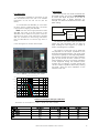
Remember: the consumption at 115Vac is double than that at 230Vac
Manual del Usuario / UX series / User’s Manual
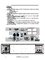
Frequency Response
500200100502020
130.0
dBSPL
120.0
110.0
100.0
90.0
80.0
AERO-20A
Mezclador / Mixer
Retardo /
Delay
UX unit
Procesador /
processor
Connections
The most common use will be combined with
the satellite system. The use of an external delay
to control and adjust the phase of the subs is
recommended (with a digital processor, for
example). The SUB units are linked with the THRU
option setting.
The OUTPUT and LOOP THRU connectors are
output XLR type connectors and are useful for
daisy chaining the same signal to a number of
boxes, connecting them in parallel.
The number of units that can be linked this
way depends on the output impedance of the
equipment driving the enclosure, such as the mixer
or processor. Typically, to avoid signal degradation,
the maximum number that can be daisy chained is
given by the formula Zc>10Zs, where Zc is the
load impedance and Zs is the output impedance
of the equipment driving the enclosure (mixer,
console, etc). For instance, a mixing console with
100 ohm output impedance allows daisy chaining
20 boxes, when the input impedance of the
cabinets is 20K ohm.
View of with LowPass Filter presets
TM
DASnet
Current consumption: AC input =230 Vrms
Low Pass Filter
As example of available low pass filters we will
view the UX-221A units case, with 4 cut available
frequencies: 50, 63, 80 and 100 Hz (see the
labels).
To use UX-221A onto Aero 20A, you must select
the 80Hz and the cardioid preset OFF. This preset
is appropriate for aligning with Aero 20A.
Note: DO NOT APPLY high pass filter IN ANY
Aero 20A! The power in the low frequency of the
Aero 20A must be added to the power of the UX-
221A and if we apply a High Pass filter to the Aero
20A, you will loose too much energy. Remember
that the Aero 20A has an internal High Pass at
60Hz.
In the next figures we will view this example.

16
Manual del Usuario / UX series / User’s Manual
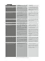
Troubleshooting
PROBLEM
No sound from the unit. The
SIGNAL LED does not light up.
Full power cannot be obtained. The
LIMIT LED never lights up.
Sound is distorted. The LIMIT LED is
not on, or only lights up occasionally.
Sound is distorted and very loud
and LIMIT LED lights up.
Hum or buzz when a mixer is
connected to the unit.
Hum or buzz when using lighting
controls in the same building.
The ON LED does not light up when
the mains connector is connected
and the unit is switched to ON.
CAUSE
1 – The signal source is sending no
signal.
2 – Defective cable.
1 - The signal source does not have
a hot enough output.
2 - If the connections are correct, It
might be overheating
1 - The mixer or signal source is
distorting.
1 - The system is overloaded and
has reached maximum power.
1.– The console probably has un-
balanced outputs. You may be using
an incorrect un-balanced to
balanced cable.
2.– The mixer and the powered
speaker are not plugged into the
same mains outlet.
3.– The audio signal cable is too
long or too close to an AC cable.
4 - DASnet ecP_xx cable is
defective.
5 - Error in DASnet Patch panel 485
net connection.
1.– The audio signal cable is too
long or too close to the lighting
cable.
2.– In a sound system with three-
phase AC, the lighting equipment
and the UNIT are connected to the
same phase.
1.– Bad or loose AC connection to
the UNIT or the mains outlet.
2 – Faulty AC cable.
3 - Internal fuse blown
SOLUTION
1 – Check that the mixer or sound
source is sending signal to the UNIT.
2 – Check that the cable from the
sound source to the UNIT is
connected correctly. Replace the
cable if defective.
1 - If using a mixer, use the
balanced output if available. Use a
professional mixer with a hotter
output.
2 - Try to cool the unit turning down
the master of the mixer.
1 - Turn mixer channel gains down.
Check that none of your signal
sources are distorting.
1 - Turn down the mixer's output.
1.– Read the appendix of this
manual to make a correct un-
balanced to balanced cable.
2.– Connect the mixer and the unit
to the same mains outlet.
3.– Use a cable that is as short as
possible and/or move the audio
signal cable away from the mains
cables.
4 - Check that there aren´t pins
crossed in CAT7 cable. Possible
short between audio par and
DASnet signal.
5 - Make sure that Audio INPUT is
not connected in DASnet INPUT and
vice versa.
1.– Move the audio signal cable
away from lighting cables. Try to find
out at what point the noise is leaking
into the system.
2.– Connect the sound system to a
different phase than the lights. You
may need the help of an electrician.
1.– Check your connections.
2.– Check the cables, connectors
and AC power with a suitable mains
tester.
3 - Replace the fuse for another of
the same size and type.

INSTALLATION AND ACCESSORIES
17
Manual del Usuario / UX series / User’s Manual
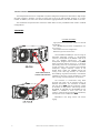
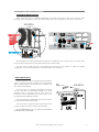
CARDIOID INSTALLATION
When boxes are flown in cardioid configuration the turned units must be fed by the front for wires'
grouping. In the next figures we can view two UX-221A units in this configuration, rear views, as example.
UX-221A
With UX-221A units, select FRONT with this switch to enable the mains connector at the front side of the
turned enclosure (enclosure 1), while select REAR for the enclosure 2.
The only case in which this way of connecting the units will not be possible is when the cardioid
configuration is made with UX-30A units, since these lack front connectors.
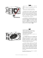
RAIN PROTECTOR
Electronic devices can be damaged when exposed to
water or moisture. The amplifiers must be protected UX
when installed outdoors. A rain protector is supplied with
each self powered unit. UX
The rain protector is specially designed to withstand
soft rain and other meteorological conditions for short
periods of time. In the case of heavy rains, storms or
permanent outdoor installations the sound system must
be protected with additional elements.
The rain protectors supplied with each unit have been
manufactured with fireproof materials.
The rain protector features several small holes on the
top side to allow convection cooling of the amplifier.
In the attached figure, we can view the rain protector
of UX-221A units, as example.
UX-221A
eCP_20
eCP_20
Select FRONT
with the switch
to enable the
mains connector
at the front side
of the turned
enclosure
Enclosure 1
Enclosure 2
1
1
2
2

18
Manual del Usuario / UX series / User’s Manual
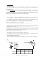
100% 65% 30% 25%
0 degrees
% Working
Load
30 degrees 45 degrees > 45 degrees
ANL-2
ANL-2
ACCESSORIES
To perform any operations related to flying the system, read the present document first, and act on the
warnings and advice given.
The goal is to the allow the user to become familiar with the mechanical elements required to fly the
acoustic system, as well as the safety measures to be taken during set-up and teardown.
Only experienced installers with adequate knowledge of the equipment and local safety regulations
should fly speaker boxes.
It is the user's responsibility to ensure that the systems to be flown (including flying accessories) comply
with state and local regulations.
The working load limits in this manual are the results of tests by independent laboratories. It is the user's
responsibility to stay within safe limits. It is the user's responsibility to follow and comply with safety factors,
resistance values, periodical supervisions and warnings given in this manual.
Product improvement by means of research and development is on going at DAS. Specifications are
subject to change without notice.
To this date, there is no international standard regarding the flying of acoustic systems. However, it is
common practice to apply 5:1 safety factors for enclosures and static elements.
For slings and elements exposed to material fatigue due to friction and load variation the following ratios
must be met; 5:1 for steel cable slings, 4:1 for steel chain slings and 7:1 polyester slings.
Thus, an element with a breaking load limit of 1000 kg may be statically loaded with 200 kg (5:1 safety
factor) and dynamically loaded with 142 Kg (7:1 safety factor).
The load capacity, of each lift motor, should be correspond to a safety factor of 10:1.
When flying a system, the working load must be lower than the resistance of each individual flying point in
the enclosure, as well as each box.
Hanging hardware should be regularly inspected and suspect units replaced if in doubt.
This is important to avoid injury and absolutely no risks should be taken in this respect. It is highly
recommended that you implement an inspection and maintenance program on flying elements, including
reports to be filled out by the personnel that will carry out the inspections.
Local regulations may exist that, in case of accident, may require you to present evidence of inspection
reports and corrective actions after defects were found.
Absolutely no risks should be taken with regards to public safety.
When flying enclosures from ceiling support structures, extreme care should be taken to assure the load
bearing capabilities of the structures so that the installation is absolutely safe.
Do not fly enclosures from unsafe structures.
Consult a certified professional if needed.
All flying accessories that are not supplied by DAS Audio are the user's responsibility. Use at your own
risk.

The ANL-2 is an optional accessory of four eyebolts and four carabiners for rigging.
To hang the units, the Allen-head screws must be removed and replaced by M10 eyebolts on one side of
the enclosure. Each rigging point has 200 kg (440 lb) working load limit.
Then choose the slings or chains of required load resistance and length, bearing in mind that the length
difference between the front and back slings or chains will determine the vertical orientation. Alternatively, the
back bottom eyebolt points can be used to provide vertical orientation.
The ANL-2 set is an optional set of four eyebolts and four carabiners. (Dimensions are in milimetres).
Each ANL-2 eyebolt has a rated working load of 200 kg. (440 lb). Each ANL-2 carabiner has a working
load of 330 kg (726 lb). If using other hardware, make sure it is rated to handle the required load.
When using eyebolts it is important to bear in mind that the rated working load is only true for a load
applied in the plane of the eye, and is significantly reduced for other angles. The drawing illustrates the
concept.
The table shows the variation of the working load as a function of the load angle. In the case of the ANL-2
eyebolt, this means that the 200 kg working load becomes 60 kg at 45 degrees. Do not use eyebolt flying if
the load angle is higher than 45 degrees.
Note: As always, when we handle heavy loads, we should wear appropriate clothing and
protective elements such as gloves, safety shoes, etc.
19
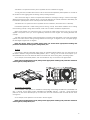
PL-221S
PL-UX218S / PL-UX218RS
PL-221S
Even though it features integrated rigging points for threaded eyebolts (ANL-2), the most practical use of
UX-221A is stacked. Using the PL-221S dolly platform (WLL = 450 kg), we can stack and transport up to
three UX-221A units; and care should be taken to avoid roll over when moving them, preventing injuries.
As an example, the PL-221S platform, with one UX-221A on top, can be seen in the figure below.
Note: when handling heavy loads, always wear appropriate clothing and protective elements
such as gloves, safety shoes, etc.
As for UX-221A, a dolly platform is available for transporting and stacking UX-218A units (PL-UX218S, with
WLL = 300 kg), and its rigging version, UX-218A-R (PL-UX218RS, with WLL = 400 kg). Using these dolly
platforms we can stack and transport up to three units; and care should be taken to avoid roll over when
moving them.
As an example, these platforms can be seen in the next figures.
Note: when handling heavy loads, always wear appropriate clothing and protective elements
such as gloves, safety shoes, etc.

20
Manual del Usuario / UX series / User’s Manual
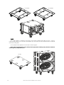
Also a dolly platform is available for transporting and stacking UX-30A units (PL-30S, with WLL = 250 kg).
Using this dolly platform we can stack and transport up to two units; and care should be taken to avoid roll
over when moving them.
As an example, these platforms can be seen in the next figures.
Note: when handling heavy loads, always wear appropriate clothing and protective elements
such as gloves, safety shoes, etc.
PL-30S
PL-UX218S
PL-UX218RS
PL-30S

21
Manual del Usuario / UX series / User’s Manual
KIT-R-UX218
AX-UX218
PICKUP-AX-AE40S3
Click
Click
RIGGING
Out of the subwoofers in this manual, only UX-218A-R can use a frame designed specifically for flying.
UX-218A can be converted to UX-218A-R by means of the KIT-R-UX218 accessory kit. Only in this way will the
enclosure be safely suspended.
Note: when handling heavy loads, always wear appropriate clothing and protective elements
such as gloves, safety shoes, etc.
Therefore, only UX-218A-R can combine with the AX-UX218 accessory frame so that enclosures can be
flown safely. If an extra pick-up point was needed, a PICKUP-AX-AE40S3 center bar could be added. This is
shared with AERO-40A systems, so that PICKUP-AX-AE40S3 allows for easy combining with these line array
systems.
These accessories can be seen in the figures below.
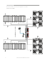
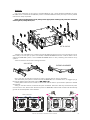
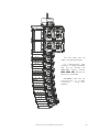
Next, we'll show an example of a line array system, with the steps on how to assemble it.
The attachment point system is similar to that of the AERO-40A, so, if unfamiliar with it, we suggest you go
through the rigging manual for these systems (RM_AE40_03).
Looking at the enclosure from the side, it can be seen that the frame is symmetrical to optimise a cardioid
arrangement.
Acting on the side controls, the attachment parts will release. We'll know that they are locked into place
once we hear a click, like the front attachment points on AERO-40A, while the side controls will automatically
go back to the initial position when released.
Side controls

22
Manual del Usuario / UX series / User’s Manual
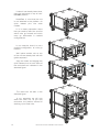
Unless it has already been done,
place the enclosure on top of a PL-
UX218RS platform.
Note: Bear in mind that the unit
is not attached to the platform via
quick release pins like other
models.
It is in these preparation steps
that you need to take into account
which units go forward and which
ones go backwards in cardioid
configurations.
In our example, since it is not a
cardioid configuration, all units go
forward.
We'll place another unit on top
of the one we already had with the
guides exposed.
Align the holes and engage the
quick release pins on both sides of
the enclosures as indicated in the
attached figure.
The result can be seen in the
attached figure.
In our examples we will only
stack two units, but, as you may
remember, the platform allows for
stacking up to three units.

23
Manual del Usuario / UX series / User’s Manual
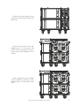
Expose the upper guides of the
units like we previously did with the
lower unit.
Place the side parts of the AX-
UX218, each on its correct side
(check the silk screening), lining up
holes of the quick release pins, as
shown.
Next, engage the quick release
pins to attach the AX parts to the
stacked units, on both sides of the
units.

24
Manual del Usuario / UX series / User’s Manual
Attach the pick-up point, or pick-up
points, to the holes in the side of the AX
parts indicated by Ease Focus, using the
quick release pins.
Remember that one pick-up bar only
provides a single pick-up point. If another
pick-up point is required, an additional
pick-up bar is needed.
Proceed to hook the assembly to the
motor (or motors, if using two pick-up
points).

25
Manual del Usuario / UX series / User’s Manual
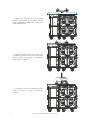
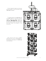
Lift the assembly slightly and remove
the dolly platform so as to be able to add
AERO-40A enclosures.
Next, place the first group of AERO-
40A below the group of UX-218A-R. In
this example, two groups of 4 AERO-40A
will be attached.
To prepare groups of 4 AERO-40A units
on PL-40S platforms, and select inter-box
angles, consult the rigging manual for
AERO-40A (RM_AE40_03), which can
be found on our website. This manual will
let you become familiar with the use of
the side controls and guides in the
enclosures.

26
Manual del Usuario / UX series / User’s Manual
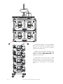
Expose the guides in the upper AERO-
40A. Once the guides are prepared and
aligned, link the two groups together
using quick release pins.
Observe the indications present in the
silkscreen lettering and use the AERO-40A
rigging manual (RM_AE40_03), as
additional information.
Furthermore, with the help of Ease
Focus software, you will know which pick-
up holes need to be used so that the final
inclination of the system is the required
one.

27
Manual del Usuario / UX series / User’s Manual
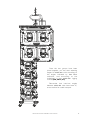
Once the two groups have been
joined together, you can start selecting
angles for AERO-40A units according to
the angles indicated by Ease Focus
software, and according to the
indications in the AERO-40A rigging
manual (RM_AE40_03).
Remember that inter-box angles
between AERO-40A units have been 0º,
so as to allow for a safe transport.

28
Manual del Usuario / UX series / User’s Manual
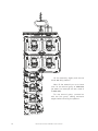
Lift the assembly slightly and remove
the PL-40S dolly platform.
Next, lift the assembly so as to leave
room for the second group of AERO-40A
(as stated, our example will use a total of
8 AERO-40A).
For the second group, proceed as
with the first group, setting enclosure
angles before removing the platform.

29
Manual del Usuario / UX series / User’s Manual
The final result can be
seen in the attached figure.
For disassembly and
transport, it is again advisable
that you go through the
AERO-40A rigging manual
(RM_AE40_03), that can be
found on our website.
UX-218A-R units can be
t r a n s p o r t e d i n t h r e e s
(maximum) using their
platform.

30
ANNEX I : Unbalanced and balanced connections
Manual del Usuario / UX series / User’s Manual
There are two basic ways to transport an audio signal with microphone or line level:
Unbalanced line: Utilising a two conductor cable, it transports the signal as the voltage between them.
Electromagnetic interference can get added to the signal as undesired noise. Connectors that carry
unbalanced signals have two pins, such as RCA (Phono) and ¼” (6.35mm, often referred to as jack) mono. 3
pin connector such as XLR (Cannon) may also carry unbalanced signals if one of the pins is unused.
Balanced line: Utilising a three conductor cable, one of them acts as a shield against electromagnetic
noise and is the ground conductor. The other two have the same voltage with respect to the ground
conductor but with opposite signs. The noise that cannot be rejected by the shield affects both signal
conductors in the same way. At the device’s input the two signals get summed with opposite sign, so that
noise is cancelled out while the programme signal doubles in level. Most professional audio devices use
balanced inputs and outputs. Connectors that can carry balanced signal have three pins, such as XLR
(Cannon) and ¼” (6.35mm) stereo.
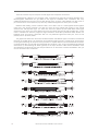
The graphs that follow show the recommended connection with different types of connectors to balanced
processor or amplifier inputs. The connectors on the left-hand side come from a signal source, and the ones
on the right hand side go to the inputs of the processor or amplifier. Note that on the unbalanced connectors
on the left-hand side, two terminals are joined inside the connector. If hum occurs with balanced to balanced
connections, try disconnecting the sleeve (ground) on the input connector. Note that the illustrations show
what should be connected to what, but that pin locations on an actual XLR connector are different. Also, pin
2 hot is assumed on XLR connectors.

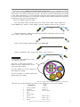
ANNEX II : DASnet cables
31
1 Orange-White Audio+ 2
2 Orange Audio- 3
3 Green-White Audio Earth 1
4 Blue
5 Blue-White
6 Green Data Earth 1
7 Brown-White Data- (A) 3
8 Brown Data+ (B) 2
etherCon XLR
Manual del Usuario / UX series / User’s Manual
With each system, cabling and patch panels are provided. It is very important to use the
system with the intended cables to prevent electromagnetic interferences between the analog
audio signal, the DASnet data and the power. Be sure to check the specifications provided
by the cable manufacturer. It is also especially important when installing connectors yourself,
to note that when termination is not accurate, a cable will be unable to achieve its maximum
performance and could have interferences.
There are 4 different types of cables:
- The main feeds which include power and a STP, CAT7 cable. These cables are
named eCP_xx (xx refers to cable length, and the standard values are 3m or 20m).
- The links between cabinets (aero40A/Convert15A/LX-218CAnet), which are STP
CAT7 cables. Cable code eC_09
- Power Links between cabinets.Cable code Plink1_09
- Links for RoadNet series. Power+STP CAT7. eCPk_1/eCPk_5
AL Shield
2 2
ecP_xx: Power cable 3x2,5mm + CAT7 4x (2 x 0,14mm )
Jacket
Jacket
The main feed cable eCP_xx has
the following structure:
STP CAT 7 cable with Aluminium
Shield for each individual pair and a
main aluminium Shield.
The main Shield has to be soldered to
the etherCon housing.
The eC_09 cable is a CAT5e cable with
global Aluminium Shield.
Important
The pin out of the EtherCon to XLR is the following on the eCP cables:

UM_UX-A_03_EN
www.dasaudio.com
DAS Audio of America, INC.
6900 NW 52th Street
Miami, FL. 33166 - U.S.A.
TOLL FREE: 1 888 DAS 4 USA
DAS Audio Asia PTE. LTD.
3 Temasek Avenue, Centennial
Tower #34-36
Singapore 039190
Tel. +65 6549 7760
DAS Audio Group, S.L.
C/. Islas Baleares, 24
46988 Fuente del Jarro
Valencia, SPAIN
Tel. +34 96 134 0860
DAS do Brasil LTDA.
Rua Dos Andradas, 382 SL
Santa Efigênia, São Paulo
Brasil. CEP: 01208-000
Tel. +551133330764
-
 1
1
-
 2
2
-
 3
3
-
 4
4
-
 5
5
-
 6
6
-
 7
7
-
 8
8
-
 9
9
-
 10
10
-
 11
11
-
 12
12
-
 13
13
-
 14
14
-
 15
15
-
 16
16
-
 17
17
-
 18
18
-
 19
19
-
 20
20
-
 21
21
-
 22
22
-
 23
23
-
 24
24
-
 25
25
-
 26
26
-
 27
27
-
 28
28
-
 29
29
-
 30
30
-
 31
31
-
 32
32


DAS UX-218A Manual de usuario
- Categoría
- Juegos de altavoces
- Tipo
- Manual de usuario
en otros idiomas
- English: DAS UX-218A User manual
Artículos relacionados
-
DAS AERO-50 Manual de usuario
-
-
-
-
-
DAS VANTEC-20A Manual de usuario
-
-
-
-