HK Audio Lucas nano 600 Manual de usuario
- Categoría
- Altavoces de la barra de sonido
- Tipo
- Manual de usuario

Manual 1.0

Version 2.3 05/2013
Important Safety Instructions! Read before
connecting!
This product has been built by the manufacturer in accordance with
IEC 60065 and left the factory in safe working order. To maintain
this condition and ensure non-risk operation, the user must
follow the advice and warning comments found in the operating
instructions. If this product shall be used in vehicles, ships or
aircraft or at altitudes exceeding 2000 m above sea level, take care
of the relevant safety regulations which may exceed the IEC 60065
requirements.
WARNING: To prevent the risk of fire and shock hazard, do not
expose this appliance to moisture or rain. Do not open case – no
user serviceable parts inside. Refer service to qualified service
personnel.
This symbol, wherever it appears, alerts you to the
presence of uninsulated dangerous voltage inside the enclosure –
voltage that may be sufficient to constitute a risk of shock.
This symbol, wherever it appears, alerts you to the
presence of externally accessible hazardous voltage. External wiring
connected to any terminal marked with this symbol must be a
“ready made cable” complying with the manufacturers
recommendations, or must be a wiring installed by instructed
persons only.
This symbol, wherever it appears, alerts you to important
operating and maintenance instructions in the accompanying
literature. Read the manual.
This symbol, wherever it appears, tells you: Take care! Hot
surface! To prevent burns you must not touch.
• Read these instructions.
• Keep these instructions.
• Follow all warnings and instructions marked on the product and
in this manual.
• Do not use this product near water. Do not place the product near
water, baths, wash basins, kitchen sinks, wet areas, swimming
pools or damp rooms.
• Do not place objects containing liquid on the product – vases,
glasses, bottles etc.
• Clean only with dry cloth.
• Do not remove any covers or sections of the housing.
• The set operating voltage of the product must match the local
mains supply voltage. If you are not sure of the type of power
available consult your dealer or local power company.
• To reduce the risk of electrical shock, the grounding of this
product must be maintained. Use only the power supply cord
provided with this product, and maintain the function of the
center (grounding) pin of the mains connection at any time. Make
sure the mains outlet used provides a proper protective ground
connection.
• Protect the power cord from being walked on or pinched
particularly at plugs, convenience receptacles, and the point
where they exit from the device! Power supply cords should
always be handled carefully. Periodically check cords for cuts or
sign of stress, especially at the plug and the point where the cord
exits the device.
• Never use a damaged power cord.
• Unplug this product during lightning storms or when unused for
long periods of time.
• This product can be fully disconnected from mains only by pulling
the mains plug at the unit or the wall socket. The product must
be placed in such a way at any time, that disconnecting from
mains is easily possible.
• Fuses: Replace with IEC127 (5x20mm) type and rated fuse for
best performance only! It is prohibited to use “patched fuses” or
to short the fuse-holder. Replacing any kind of fuses must only be
carried out by qualified service personal.
• Refer all servicing to qualified service personnel. Servicing is
required when the unit has been damaged in any way, such as:
- When the power cord or plug is damaged or frayed.
- If liquid has been spilled or objects have fallen into the product.
- If the product has been exposed to rain or moisture.
- If the product does not operate normally when the operating
instructions are followed.
- If the product has been dropped or the cabinet has been
damaged.
• Do not connect external speakers to this product with an
impedance lower than the rated impedance given on the product
or in this manual. Use only cables with sufficient cross section
according to the local safety regulations.
• Keep away from direct sunlight.
• Do not install near heat sources such as radiators, heat registers,
stoves or other devices that produce heat.
• Do not block any ventilation openings. Install in accordance with
manufacturer’s instructions. This product must not be placed in
a built-in installation such as a rack unless proper ventilation is
provided.
• Always allow a cold device to warm up to ambient temperature,
when being moved into a room. Condensation can form inside it
and damage the product, when being used without warming up.
• Do not place naked flame sources, such as lighted candles on
the product.
• The device must be positioned at least 20 cm/8“ away from
walls.
• Use only with the cart, stand, tripod, bracket or table specified by
the manufacturer or sold with the product. When a cart is used,
use caution when moving the cart/product combination to avoid
injury from tip-over.
• Use only accessories recommended by the manufacturer, this
applies for all kind of accessories, for example protective covers,
transport bags, stands, wall or ceiling mounting equipment. In
case of attaching any kind of accessories to the product, always
follow the instructions for use, provided by the manufacturer.
Never use fixing points on the product other than specified by the
manufacturer.
• This appliance is NOT suitable to be used by any person or
persons (including children) with limited physical, sensorical or
mental ability, or by persons with insufficient experience and/or
knowledge to operate such an appliance. Children under 4 years
of age must be kept away from this appliance at all times.
• Never push objects of any kind into this product through cabinet
slots as they may touch dangerous voltage points or short out
parts that could result in risk of fire or electric shock.
• This product is capable of delivering sound pressure levels in
excess of 90 dB, which may cause permanent hearing damage!
Exposure to extremely high noise levels may cause a permanent
hearing loss. Wear hearing protection if continously exposed to
such high levels.
• The manufacturer only guarantees the safety, reliability and
efficiency of this product if:
- Assembly, extension, re-adjustment, modifications or repairs are
carried out by the manufacturer or by persons authorized to do so.
- The electrical installation of the relevant area complies with the
requirements of IEC (ANSI) specifications.
- The unit is used in accordance with the operating instructions.
• This product is optimized for use with music and speech signals.
Using this product with sine wave, square wave or other kind of
measuring signals at higher level may lead to severe damage of
the product.
General Notes on Safety for Loudspeaker
Systems
Mounting systems may only be used for those loudspeaker
systems authorized by the manufacturer and only with the mounting
accessories specified by the manufacturer in the installation
instructions. Read and heed the manufacturer’s installation
instructions. The indicated load-bearing capacity cannot be
guaranteed and the manufacturer will not be liable for damages in
the event of improper installation or the use of unauthorized
mounting accessories.
The system’s load-bearing capacity cannot be guaranteed and
the manufacturer will not be liable for damages in the event that
loudspeakers, mounting accessories, and connecting and attaching
components are modified in any way.
Components affecting safety may only be repaired by the
manufacturer or authorized agents, otherwise the operating permit
will be voided.
Installation may be performed qualified personnel only, and
then only at pick-points with sufficient load-carrying capacity and
in compliance with local building regulations. Use only the mounting
hardware specified by the manufacturer in the installation
instructions (screws, anchors, etc.). Take all the precautions
necessary to ensure bolted connections and other threaded locking
devices will not loosen.
Fixed and portable installations (in this case, speakers and
mounting accessories) must be secured by two independent
safeties to prevent them from falling. Safeties must be able to catch
accessories or parts that are loose or may become loose. Ensure
compliance with the given national regulations when using
connecting, attaching, and rigging devices. Factor potential dynamic
forces (jerk) into the equation when determining the proper size
and load-bearing capacity of safeties.
Be sure to observe speaker stands’ maximum load-bearing
capacity. Note that for reasons of design and construction, most
speaker stands are approved to bear centric loads only; that is, the
speakers’ mass has to be precisely centered and balanced. Ensure
speaker stands are set up stably and securely. Take appropriate
added measures to secure speaker stands, for example when:
- the floor or ground surface does not provide a stable, secure
base.
- they are extended to heights that impede stability.
- high wind pressure may be expected.
- there is the risk that they may be knocked over by people.
Special measures may become necessary as precautions against
unsafe audience behavior. Do not set up speaker stands in
evacuation routes and emergency exits. Ensure corridors are wide
enough and put proper barriers and markings in place when setting
speaker stands up in passageways. Mounting and dismounting
are especially hazardous tasks. Use aids suitable for this purpose.
Observe the given national regulations when doing so.
Wear proper protection (in particular, a helmet, gloves, and
safety shoes) and use only suitable means of ascent (ladders,
scaffolds, etc.) during installation. Compliance with this requirement
is the sole responsibility of the company performing the installation.
WARNING!
After installation, inspect the system comprised of the mounting
fixtures and loudspeakers to ensure it is properly secured.
The operator of loudspeaker systems (fixed or portable) must
regularly inspect or task a third party to regularly inspect all system
components in accordance with the given country’s regulations and
have possible defects repaired immediately.
We also strongly recommend maintaining a logbook or the like to
document all inspections.
When installing speakers for longer lasting or permanent outdoor
operation, be sure to take into account the stability and load-
bearing capacity of platforms and surfaces; loads and forces
exerted by wind, snow, and ice; as well as thermal influences. Also
be sure to provide sufficient safety margins for the rigging points
used for flown systems. Observe the given national regulations
when doing so.
• Ask the manufacturer if your product is allowed for outdoor
usage !
Professional loudspeaker systems can produce harmful
volume levels. Even prolonged exposure to seemingly harmless
levels (starting at about 95 dBA SPL) can cause permanent hearing
damage! Therefore we recommend that everyone who is exposed to
high volume levels produced by loudspeaker systems wears
professional hearing protection (earplugs or earmuffs).
Manufacturer: Stamer Musikanlagen GmbH, Magdeburger Str. 8,
66606 St. Wendel, Germany

Lucas Nano 600 1.0
3
Welcome to the HK Audio family!
Thank you for choosing a brand-name product made by our company.
Rest assured, we engineered and built it with the greatest care so it will
serve you well for many tomorrows to come.
Even if your experience with sound systems runs deep, some things
about this product are sure to be new to you. This is why we ask that
you do not set this manual aside without reading it first. Be sure to
keep it in a safe place for later reference.
Here’s wishing you the best sound at every occasion!
Your HK Audio team
Warranty
Register your LUCAS NANO 600 to extend your warranty to five years
free of charge! Use the convenient online registration option at
www.hkaudio.com.
If you are unable to register online, please fill out the enclosed warranty
card, ensuring all information is legible and complete, and mail or fax
it to us.
The registration is only valid if the warranty registration card is
filled out and returned to HK AUDIO or the device is registered via
Internet within 30 days of the date of purchase.
We are also interested in learning where and by whom our devices are
used. This information will help us design future products. Your data
are of course protected by German privacy laws.
Thank you!
HK AUDIO
Technischer Service
Postfach 1509
66959 St. Wendel, Germany
Fax: +49 6851 905 100
• Español• English • Deutsch • Français • Italiano
•
•

Lucas Nano 600 1.0
4
1 General Information
1.1 Unpacking and Inventorying
Remove all the component parts of LUCAS NANO 600 from the carton
and make sure you have received all items.
LUCAS NANO 600 consists of a subwoofer and two satellites.
Aprotective cover and a mains cable are also included.
1.2 Unfastening Transport Latches
Latches secure the LUCAS NANO 600 satellites to the subwoofer to
protect them during transport. Here’s how to undo them:
• Set the subwoofer with front of the speaker facing down and turn the
locking knobs on both sides rearward to unlock the satellites. Remove
the two LUCAS NANO 600 satellites from their cradle.
• Always make sure these knobs engage to lock the speakers down for
transport.
1.3 Easy Click Connector
• This mechanical and electric coupler connects the modules.
• To release the Easy Click latch, hold the pair of satellites with their
back panels facing you so that you can read the inscription Push to
Release on the one satellite. Push this satellite forward and then lift
straight up to remove it.
• To secure the Easy Click latch, hold the satellite with the inscription
Push to Connect with the back facing you and the pole mount pointing
up so you can read this inscription. Hold the top satellite upright with
the pole mount facing up as you lower and insert it into the Easy Click
connector, and then push forward.
1.4 Pole Mount on the Subwoofer
This M20 internally threaded shaft on top of the subwoofer accepts a
speaker extension pole with a diameter of 35 mm such as the optional
LUCAS NANO 600 MONO STAND ADD-ON.
1.5 Pole Mount on the Satellites
This 3/8" internally threaded shaft on LUCAS NANO 600 satellites
serves to mount the satellites to poles, tripods and microphone stands
with an externally threaded 3/8" tip.

Lucas Nano 600 1.0
5
2 Connectors and Controls
Out
Link In/Out
Sub
Mode Setup
Balance
A: Rec Out
B: CH 2 Thru
Bal.
Connect a 2nd
LUCAS NANO
L R LR L R
Stereo
LR
AB
Mute
1 2 3
Speaker Out
to Satellite
OnOff
Speaker Out
to Satellite
L
R
6OO
nano
Lucas
Phantom Power
CH 1 Mic
2.1 Power/Status Section
12
1 Standby
This switches LUCAS NANO 600 on and standby.
2 Status Indicator
Dual-color LED (green = power on, red =limit/error). The LED briefly
flashes red to tell you the limiter is responding to signal peaks.
Heads up! If the Status LED stays red while the system is fully
operational, it is being overloaded. Turn down the signal level! If you
are not feeding a signal into the system and the Status LED stays
red, there has been malfunction.
Note: LUCAS NANO 600 remains muted for about five seconds after
you power it up. The Status LED lights up red during this time and turns
green once the system is fully operational.
2.2 Input Section 1
3 Volume
This rotary knob adjusts the volume for this input.
Twist it counterclockwise to the far left to turn the
signal level all the way down and clockwise to the
far right to turn the level all the way up.
4 Mic/Instrument/Line
Use this switch to match Input 1’s gain and
impedance to a microphone, an instrument such
as a guitar or a line signal. This button also sets
the integrated filter to Voice for microphones or to
Contour for instrument and line signals.
5 Voice/Contour
Use this knob to tune the incoming signal’s tone. The Mic/Instrument/
Line setting determines how the Voice/Contour knob shapes the signal’s
frequencies.
• This rotary knob tunes this channel to render speech when the Mic/
Line switch is set to Mic.
Far left position = no change in tone
Far right position = maximum effect
• This knob tunes this channel for music produced by instruments or
line sources when the Mic/Instrument/Line switch is set to Instrument
or Line. Specifically, it boosts low and high frequencies while cutting
midrange frequencies.
Far left position = no change in tone
Far right position = maximum effect
6 Input 1
Use this electronically balanced combo input [mono XLR/ 1/4" (6.3 mm)]
to patch in a microphone or line signal. Feel free to use a dynamic,
condenser or lavalier microphone with this channel. If you’re using a
condenser or lavalier mic that requires power to operate, engage the
Phantom Power (23) button. The input signal is routed to both the left
and right outputs of LUCAS NANO 600.
2.3 Input Section 2
7 Volume
See Input Section 1 for a description.
8 Mic-Instrument/Line
Use this switch to match Input 2’s gain and
impedance to a dynamic microphone and an
instrument such as a guitar or a line signal.
Set it to the left to blend the input signals.
This composite mono signal is then rendered
by both the right and left speakers. Use the
instrument’s volume knob to control the
balance of the microphone and instrument
signals.
9 Voice/Contour
Use this knob to tune the incoming signal’s tone. The Mic/Instrument/
Line setting determines how the Voice/Contour knob shapes the signal’s
frequencies.
• This rotary knob tunes this channel to render speech when the Mic-
Instrument/Line switch is set to Mic-Instrument. Adjust the tone
separately for each of the two channels using the Voice/ Contour
knob to dial in the best results for speech/ vocals and instruments,
respectively.
Far left position = no change in tone
Far right position = maximum effect
• This knob tunes this channel for music produced by instruments or
line sources when the Mic-Instrument/Line switch is set to Instrument
or Line. Specifically, it boosts low and high frequencies while cutting
midrange frequencies.
Far left position = no change in tone
Far right position = maximum effect
10 Input 2 L/R
This multipurpose XLR/1/4" (6.3 mm) mono
input is electrically balanced to accept an
instrument or a stereo line signal. Note that
L/R means stage left and stage right from
the perspective of a performer looking out
towards the audience.
1
3
4
6
5
LR
2
7
8
9
10
Stage
Left
Stage
Right
• Español• English • Deutsch • Français • Italiano
•
•

Lucas Nano 600 1.0
6
2.4 Input Section 3
11 Volume
See Input Section 1 for a description.
12 Mini-Jack Input (3.5 mm)
Use this stereo input to connect MP3 players or
the headphones output of a laptop.
Heads up: Plugging a connector into this input
mutes the Stereo RCA Input (14).
13 Contour
This rotary knob adjusts the audio signal’s tone. It
also rolls off midrange frequencies when it boosts
high and low frequencies.
• Far left position = no change in tone
• Far right position = maximum effect
14 Stereo RCA Input
Use this RCA jack (also called a phono or cinch jack) to connect audio
sources such as CD/ DVD players, keyboards, DJ mixing consoles and
computers that provide unbalanced, high-gain signals. Note that L/R
means stage left and stage right from the perspective of a performer
looking out towards the audience.
2.5 Output Section
15 Sub
This rotary knob adjusts the subwoofer’s volume level from -∞ to +6 dB.
16 Balance
This rotary knob adjusts the relative levels of the left and right channels.
17 Mode A/B
This switch configures the output signal
sent to Out L/R (19):
• A: Rec Out: This mode sends the
composite signal of channels 1 to 3
and Link In (20) to a connected audio
recorder.
• B: Ch 2 Thru: This mode sends the
signal routed into Input 2 (10) through
to this output for monitoring. See the
example in the appendix called Personal
Monitoring.
18 Out L/R
This is an electrically balanced 1/4" (6.3 mm) output jack. Depending
on the Mode A/B switch setting, it sends out a composite of all input
signals (including Link In) or just the signal patched into Input 2.
19 Setup
Use this switch to configure LUCAS NANO 600 for single or twin
operation. LUCAS NANO 600 is muted for about five seconds after you
press the Setup switch to prevent switching noise.
The status LED turns red during this time and changes
back to green when the system is ready for operation.
20 Link In/Out
This 1/4" (6.3 mm) stereo jack serves to connect this LUCAS NANO 600
to another LUCAS NANO 600 or NANO 300. Please be sure to use a
cord equipped with stereo 1/4" (6.3 mm) jack plugs to do this. No other
cables will do.
You can use both mixing consoles simultaneously when operating two
LUCAS NANO 600s as a double stereo set as shown in the DJ and
Band + Recording examples on page 62 of the appendix. This increases
the overall system’s input channel count to six (10 inputs), the signals of
which are rendered in stereo.
A great way to cover two rooms is to combine a LUCAS NANO 600
and a LUCAS NANO 300 system in Link mode (see page 63 of the
appendix).
2.6 Speaker Out Section
Speaker Out
to Satellite
OnOff
Speaker Out
to Satellite
L R
6OO
nano
Lucas
Phantom Power
CH 1 Mic
21
22 23 22
21
21 Speaker Out to Satellite L / R
Connect the Speaker outputs – they’re compatible with Speakon
connectors – to the left and right LUCAS NANO 600 satellites using
speaker cables equipped with Speakon NL2-compatible connectors
(+1/-1). Do not connect any other devices. If you do, that device and
LUCAS NANO 600 may be irreparably damaged. Note: Be sure to rotate
speaker connectors clockwise until they lock in place!
22 Speaker Status Indicators
This dual-color LED tells you what’s going on with the Speaker Outs of
LUCAS NANO 600 (green = speaker output is active, red = inactive).
Enable and disable outputs using the Setup switch in the output section.
Note: LUCAS NANO 600’s outputs are muted during a system check
(see Status LED). The Speaker Status LEDs light up red during this
time (about 5 seconds).
23 Phantom Power Ch 1 Mic
This switch activates phantom power for a mic that you have connected
to Channel 1. Please check if your microphone requires this power
before you engage the switch. LUCAS NANO 600 is muted for about five
seconds after you press the Phantom Power switch to prevent switching
noise. The status LED lights up red during this time and changes back
to green when the system is ready for operation.
2.7 Connector Panel
Auto Sleep (Auto Stand-by)
LUCAS NANO 600 also features an Auto Sleep function. Its on/off
switch is in the satellite transport bay. The system comes with the
switch set to the On position (Auto Sleep function enabled). If LUCAS
NANO 600 does not get an input signal for no less than 120 minutes,
the power amp will go into hibernation. To power the system up again,
engage the Power On/Off switch or disconnect and reconnect mains
power. Set Auto Sleep (Auto Stand-by) to the Off position if you wish
to disable this function and ensure LUCAS NANO 600 remains up and
running.
Mains Socket
Use the factory-included mains cord to connect this socket to a wall
outlet.
Caution! Make sure the local mains voltage matches the voltage
specified on LUCAS NANO 600. Connecting it to the wrong mains
voltage may destroy its electronic components.
Out
Link In/Out
Sub
Mode Setup
Balance
Bal.
Connect a 2nd
LUCAS NANO
LR
Stereo
LR
AB
A: Rec Out
B: CH 2 Thru
15 16
17 19
18 20
LR
Mute
3
11
12
13
14
Single Twin

Lucas Nano 600 1.0
7
3 Setups
LUCAS NANO 600 ADD-ON sets afford you the greatest flexibility when
it comes to configuration. These are sold separately.
1. LUCAS NANO 600 MONO STAND ADD-ON
Contains one each two-piece speaker pole, stand adapter, speaker cord and bag
2. LUCAS NANO 600 STEREO STAND ADD-ON
Contains two each adjustable speaker tripods and speaker cords, plus one bag
3. LUCAS NANO POLE MOUNT ADAPTER
Contains two adapters for speaker stands with a diameter of 35 mm
4. LUCAS NANO DOUBLE STEREO CABLE
Contains one stereo cord with 1/4" (6.3 mm) jack plugs to connect LUCAS NANO 600s
5. LUCAS NANO 600 ROLLER BAG
Contains one padded trolley
6. LUCAS NANO 600 DESK / WALL MOUNT
Contains two each wall / tabletop mounts, cords and 1/4" (6.3 mm) speaker plug adapters
You can use LUCAS NANO 600 in various configurations.
The following examples should help you to find the best setup for
your application:
3.1 Mono System 1
Stack and secure the LUCAS NANO 600 satellites as described in
section 1.3, Easy Click Connector, for operation in Twin mode. To
connect the pair of satellites to the subwoofer, hold them upright as you
lower and insert them into the shaft and then push forward. Be sure to
set the Setup switch to Twin.
3.2 Mono System 2
Stack and secure the LUCAS NANO 600 satellites as described in
section 1.3, Easy Click Connector, for operation in Twin mode. Screw
the M20 threading on the lower end of the speaker extension pole
1
(ø35mm) into the mounting plate on top of the subwoofer. Place the
pole mount adapter
2
on the speaker extension pole and secure the
pair of satellites on the mounting plate by engaging the Easy Click
connector. To do this, hold the pair of satellites upright, insert them in
the shaft and then push forward. Use an speaker cord
1
with Speakon-
compatible plugs to connect the LUCAS NANO 600 subwoofer’s
Speaker Out to Satellite L to the pair of satellites. Be sure to set the
Setup switch to Twin.
3.3 Stereo System
Attach each of the two LUCAS NANO 600 satellites to a tripod
3
using a
speaker extension pole with an 3/8" threaded tip. Use optional
3
speaker
cords with Speakon-compatible plugs to connect the subwoofer’s
Speaker Out to Satellite L output to the left satellite. Then connect the
Speaker Out to Satellite R output to the right satellite. Be sure to set the
Setup switch to Single mode.
3.4 Double Stereo System
(Two LUCAS NANO 600 Systems)
Stack and secure the LUCAS NANO 600 satellites as described in
section 1.3, Easy Click Connector, for operation in Twin mode. Then
screw an M20 speaker pole
1
into the pole mount on top of each
subwoofer and attach two satellites to each pole. Attach the pole mount
adapter
3
to the speaker extension pole and secure each pair of satellites
to the mounting plate by engaging the Easy Click connector. To do this,
hold the pair of satellites upright, insert them in the shaft and then push
forward. Use an speaker cord
1
equipped with Speakon-compatible plugs
to connect the subwoofers’ Speaker Out to Satellite L outputs to the
pairs of satellites. Be sure to set the Setup switch to Twin.
You can use both mixing consoles simultaneously when operating two
LUCAS NANO 600s as a double stereo set as shown in the DJ and
Band + Recording examples on page 62 of the appendix. This increases
the overall system’s input channel count to six, the signals of which are
rendered in stereo.
Use a cord
4
equipped with stereo 1/4" (6.3 mm) jack plugs to connect
the two LUCAS NANO 600 subwoofers’ Link In/Out ports and configure
a double stereo system. Be sure to set the subwoofers’ Balance knobs
accordingly: Turn the left sub’s knob to the left and the right sub’s to the
right.
You’ll find examples of more applications with two combined LUCAS
NANO 600 systems, for example, to cover two rooms, in the appendix
starting on page 58.
1
) Part of the optional LUCAS NANO 600 MONO STAND ADD-ON
2
) Part of the optional LUCAS NANO 600 MONO STAND ADD-ON and the LUCAS NANO POLE MOUNT
ADAPTER set
3
) Part of the optional LUCAS NANO 600 STEREO STAND ADD-ON
4
) Part of the optional LUCAS NANO DOUBLE STEREO CABLE set
• Español• English • Deutsch • Français • Italiano
•
•

Lucas Nano 600 1.0
8
4 Aiming Satellites
4.1 Vertical Alignment
To treat your audience to the most balanced audio image, always aim
LUCAS NANO 600 satellites level with their ears.
The vertical directivity of a single satellite in stereo mode is +10°x-45°.
Doubling up the satellite in Twin mode changes the overall vertical
directivity to 60°.
4.2 Horizontal Alignment
The satellites’ horizontal dispersion angle is around 90°. Depending on
room size and whether it’s a mono or stereo setup, you may want to
turn the satellites in towards the audience area.
StereoMono
5 Example Applications
You’ll find more examples of applications, configurations and setups in
the appendix starting on page 58, including setups for:
• Presentations
• Entertainers
• Instrument/ vocals with live recording
• Keyboard monitoring on stage
• E-drum monitoring at home
• Personal monitoring for e-drums
• DJs
• Setup, cabling and alignment when using two LUCAS NANO 600
systems
6 Technical Specifi cations
Subwoofer
Power output 300 W @ 8 ohms
Dimensions (WxHxD) 35 x 49 x 47 cm
Weight 13.9 kg / 30.86 lbs
Satellite Single (1 Top) Twin (2 Tops)
Power output 80 W @ 8 ohms 160 W @ 4 ohms
Dimensions (WxHxD) 14,5 x 14,5 x 13,5 cm 14,5 x 28 x 13,5 cm
Weight 1.2 kg / 2.65 lbs 2.4 kg / 5.29 lbs
General Technical Specifications
Peak current:
3 A / 220-240 V AC • 6 A / 100-120 V AC
Current consumption pursuant to EN 60065:*
0.7 A / 220-240 V AC • 1.5 A / 100-120 V AC
Inrush current: 70 A at 120 V and 230 V
*) Current consumption (mains power) was measured at the internal amplifier‘s output at
1/8power by inputting a sine wave as specified in the EN60065 standard. This value represents
the average current drawn from the mains grid when operating the system with standard
musicsignals.

Lucas Nano 600 1.0
9
• Español• English • Deutsch • Français • Italiano
•
•

Version 2.3 05/2013
Wichtige Sicherheitshinweise! Bitte vor
Anschluss lesen!
Dieses Produkt wurde gemäß IEC 60065 hergestellt und hat
das Werk in einem sicheren, betriebsfähigen Zustand verlassen.
Um diesen Zustand zu erhalten und um einen gefahrlosen
Betrieb zu gewährleisten, ist es notwendig, dass der Benutzer
die Empfehlungen und Warnhinweise befolgt, die in der
Betriebsanleitung zu finden sind. Bei Einsatz dieses Produktes in
Fahrzeugen, Schiffen oder Flugzeugen, oder in Höhen oberhalb 2000
m Meereshöhe müssen die entsprechenden Sicherheitsstandards
zusätzlich zur IEC 60065 beachtet werden.
WARNUNG: Um das Risiko von Feuer oder Stromschlag zu verhüten,
darf dieses Gerät nicht Feuchtigkeit oder Regen ausgesetzt werden.
Öffnen Sie das Gehäuse nicht – im Inneren gibt es keine Bauteile,
die vom Benutzer wartbar sind. Die Wartung darf nur von einem
qualifiziertem Kundendienst durchgeführt werden.
Dieses Symbol, wo immer es erscheint, warnt Sie vor
gefährlicher, nicht isolierter Spannung im Gehäuse – Spannung, die
möglicherweise genügt, eine Stromschlaggefahr darzustellen.
Dieses Symbol, wo immer es erscheint, warnt Sie vor außen
zugänglicher, gefährlicher Spannung. Eine Verbindung zu jeder
Anschlussklemme, die mit diesem Symbol versehen ist, darf nur mit
konfektioniertem Kabel hergestellt werden, dass den Empfehlungen
des Herstellers genügt, oder mit Kabel, das von qualifiziertem
Personal installiert wurde.
Dieses Symbol, wo immer es erscheint, macht Sie auf
wichtige Bedienungs- und Wartungsanweisungen aufmerksam, die in
beiliegenden Unterlagen zu finden sind. Bitte lesen Sie das
Handbuch.
Dieses Symbol, wo immer es erscheint, sagt Ihnen:
Vorsicht! Heiße Oberfläche! Um Verbrennungen zu vermeiden, nicht
anfassen.
• Bitte lesen Sie diese Anweisungen.
• Bewahren Sie diese Anweisungen auf.
• Befolgen Sie alle Warnhinweise und Anweisungen auf dem Gerät
und in dieser Anleitung.
• Benutzen Sie dieses Gerät nicht in der Nähe von Wasser. Stellen
Sie das Gerät nicht in der Nähe von Wasser, Badewannen,
Waschbecken, Küchenspülen, nassen Stellen, Schwimmbecken
oder in feuchten Räumen auf.
• Stellen Sie keine Gefäße, wie Vasen, Gläser, Flaschen usw., die
Flüssigkeiten enthalten, auf das Gerät.
• Reinigen Sie das Gerät nur mit einem trockenen Tuch.
• Entfernen Sie keine Abdeckungen oder Teile des Gehäuses.
• Die auf dem Gerät angegebene Betriebsspannung muss mit der
örtlichen Spannung der Netzstromversorgung übereinstimmen.
Wenn Sie sich nicht sicher sind, welche Spannung in Ihrem Netz
zur Verfügung steht, konsultieren Sie bitte Ihren Händler oder den
örtlichen Stromversorger.
• Um das Risiko eines Stromschlags zu verringern, muss die
Erdung des Gerätes beibehalten werden. Verwenden Sie nur das
mitgelieferte Stromführungskabel und behalten Sie die Funktion
der seitlichen, geerdeten Schutzkontakte des Netzanschlusses
immer aufrecht. Stellen Sie sicher, dass das Gerät nur an
Steckdosen angeschlossen wird, die über eine ordnungsgemäß
funktionierende Schutzerde verfügen.
• Schützen Sie das Stromführungskabel vor Betreten und Quetschen,
besonders in der Nähe der Stecker, Gerätesteckdosen – und
dort, wo sie am Gerät austreten! Stromführungskabel sollten
immer vorsichtig behandelt werden. Kontrollieren Sie die
Stromführungskabel in regelmäßigen Abständen auf Einschnitte
und Anzeichen von Abnutzung, besonders in der Nähe des Steckers
und an der Verbindung zum Gerät.
• Benutzen Sie niemals ein beschädigtes Stromführungskabel.
• Ziehen Sie bei Gewittern den Stecker des Gerätes und wenn das
Gerät über einen längeren Zeitraum nicht benutzt wird.
• Dieses Gerät wird nur vollständig von Stromnetz getrennt, wenn
der Stecker vom Gerät oder aus der Steckdose gezogen wird.
Das Gerät sollte so aufgestellt werden, dass das Trennen vom
Stromnetz leicht möglich ist.
• Sicherungen: Ersetzen Sie Sicherungen nur mit dem Typ IEC127
(5x20mm) und dem korrekten Nennwert, um die optimale Leistung
zu gewährleisten! Es ist untersagt, kurzgeschlossene Sicherungen
zu verwenden oder den Sicherungshalter zu überbrücken.
Sicherungen dürfen nur von qualifiziertem Personal gewechselt
werden.
• Alle Wartungsarbeiten sollten nur von qualifiziertem Personal
ausgeführt werden. Wartung ist notwendig, wenn das Gerät auf
irgendeine Weise beschädigt wurde, wie zum Beispiel:
- Wenn das Stromführungskabel oder der Stecker beschädigt oder
abgenutzt ist.
- Wenn Flüssigkeit oder Gegenstände in das Gerät gelangt sind.
- Wenn das Gerät Regen oder Feuchtigkeit ausgesetzt war.
- Wenn das Gerät nicht ordnungsgemäß funktioniert, obwohl die
Bedienungsanleitung beachtet wurde.
- Wenn das Gerät hingefallen ist oder das Gehäuse beschädigt
wurde.
• Beim Anschluss von Lautsprechern an dieses Gerät darf die auf
dem Gerät oder in dieser Anleitung angegebene Mindestimpedanz
nicht unterschritten werden. Die verwendeten Kabel müssen
entsprechend den lokalen Regelungen über einen ausreichenden
Querschnitt verfügen.
• Halten Sie das Gerät vom Sonnenlicht fern.
• Installieren Sie das Gerät nicht in der Nähe von Wärmequellen, wie
zum Beispiel Heizkörper, Heizregister, Öfen oder anderen Geräten,
die Hitze erzeugen.
• Verstopfen Sie nicht die Lüftungsöffnungen. Installieren Sie das
Gerät entsprechend der Anleitung des Herstellers. Das Gerät darf
nicht eingebaut werden – wie zum Beispiel in einen Gestellrahmen,
es sei denn, dass für angemessene Belüftung gesorgt wird.
• Ein kaltes Gerät sollte immer auf die Umgebungstemperatur
erwärmt werden, wenn es in einen Raum transportiert wird.
Es könnte sich Kondensation im Inneren bilden, die das Gerät
beschädigt, wenn es ohne vorherige Erwärmung benutzt wird.
• Stellen Sie keine offenen Flammen, wie brennende Kerzen, auf
das Gerät.
• Das Gerät sollte mindestens 20 cm von Wänden aufgestellt
werden.
• Das Gerät darf nur mit Rollwagen, Ständern, Stativen, Tischen
oder Halterungen benutzt werden, die vom Hersteller spezifiziert
sind oder zusammen mit dem Gerät verkauft wurden. Wenn
ein Rollwagen benutzt wird, seien Sie vorsichtig, wenn Sie die
Rollwagen/Geräte-Kombination transportieren, um Verletzungen
durch Umkippen zu vermeiden.
• Verwenden Sie nur Zubehör, das vom Hersteller empfohlen
ist. Das gilt für alle Arten von Zubehör, wie zum Beispiel
Schutzabdeckungen, Transporttaschen, Ständer sowie Wand-
und Deckenhalterungen. Wenn Sie irgendein Zubehör am Gerät
anbringen, befolgen Sie immer die Anleitungen des Herstellers.
Benutzen Sie nur die Befestigungspunkte des Geräts, die vom
Hersteller vorgesehen sind.
• Dieses Gerät ist NICHT geeignet für eine Person oder Personen
(einschließlich Kindern) mit eingeschränkten physischen,
sensorischen und geistigen Fähigkeiten, oder für Personen mit
unzulänglicher Erfahrung und/oder Fachkenntnis, um solch ein
Gerät zu bedienen. Kinder unter 4 Jahren sollten stets von diesem
Gerät fern gehalten werden.
• Es sollten keinerlei Gegenstände durch die Gehäuseschlitze
eingeführt werden, da dadurch gefährliche, spannungsführende
Bauteile berührt oder kurzgeschlossen werden können. Dies
könnte zu einer Feuer- oder Stromschlaggefahr führen.
• Dieses Gerät ist imstande, Schalldruckpegel von mehr als 90 dB
zu produzieren. Dies könnte zu einem dauerhaften Hörschaden
führen! Eine Belastung durch extrem hohe Geräuschpegel kann
zu einem dauerhaften Gehörverlust führen. Bei einer anhaltenden
Belastung durch solch hohe Pegel sollte ein Gehörschutz getragen
werden.
• Der Hersteller gewährleistet die Sicherheit, Zuverlässigkeit und
Leistung des Gerätes nur unter folgenden Voraussetzungen:
- Einbau, Erweiterung, Neueinstellung, Modifikationen oder
Reparaturen werden vom Hersteller oder autorisiertem Personal
ausgeführt.
- Die elektrische Installation des betreffenden Bereiches entspricht
den Anforderungen der IEC (ANSI) Maßgaben.
- Das Gerät wird entsprechend der Bedienungsanleitung benutzt.
• Dieses Produkt ist auf die Verwendung mit Musik- und Sprach-
signalen optimiert. Verwendung mit Sinus-, Rechteck- oder
anderen Mess-Signalen bei höherem Pegel kann zu ernsten
Beschädigungen des Geräts führen.
Allgemeine Sicherheitshinweise für
Lautsprechersysteme
Befestigungssysteme dürfen ausschließlich für die vom
Hersteller freigegebenen Lautsprechersysteme und mit dem in der
Montageanleitung genannten Montage-Zubehör verwendet werden.
Die Montagehinweise des Herstellers sind dabei unbedingt zu
beachten. Bei unsachgemäßer Montage bzw. Verwendung von nicht
freigegebenem Montage-Zubehör kann die angegebene Belastung
nicht garantiert und keinerlei Haftung seitens des Herstellers
übernommen werden.
Sollten Änderungen an Lautsprechern, an Montage-Zubehör,
Verbindungs- und Befestigungselementen sowie Anschlagmitteln
vorgenommen werden, kann die Tragfähigkeit des Systems nicht
mehr garantiert werden und seitens des Hersteller keinerlei Haftung
übernommen werden.
Reparaturen an sicherheitsrelevanten Bauteilen dürfen nur vom
Hersteller oder Bevollmächtigten durchgeführt werden, andernfalls
erlischt die Betriebserlaubnis.
Die Installation darf ausschließlich durch Sachkundige und
nur an Montagepunkten mit ausreichender Tragfähigkeit, ggf. unter
der Berücksichtigung von Bauauflagen, erfolgen. Das vom Hersteller
in der Montageanleitung vorgeschriebene Befestigungsmaterial
(Schrauben, Dübel, etc.) muss verwendet werden.
Schraubverbindungen müssen durch geeignete Maßnahmen gegen
Lösen gesichert sein.
Ortsfeste oder mobile Installationen (hier Lautsprecher inkl.
Montagezubehör) müssen durch zwei unabhängig voneinander
wirkende Einrichtungen gegen Herabfallen gesichert sein. Lose
Zusatzteile oder sich lösende Teile müssen durch geeignete
Einrichtungen aufgefangen werden können. Bei Verwendung von
Verbindungs- und Befestigungselementen sowie Anschlagmitteln
sind die nationalen Vorschriften zu beachten. Hinsichtlich der
Bemessung der Sicherungsmittel sind mögliche dynamische
Belastungen (Ruckkräfte) mit zu berücksichtigen.
Bei Stativen ist vor allem die maximale Traglast zu beachten.
Außerdem sind die meisten Stative aus konstruktiven Gründen nur
für das Tragen von genau zentrischer Belastung zugelassen. Stative
müssen standsicher aufgestellt werden. Stative sind durch geeignete
Maßnahmen zusätzlich zu sichern, wenn zum Beispiel:
- ihre Aufstandfläche keinen sicheren Stand zulässt,
- ihre Höhen die Standsicherheit einschränken,
- mit zu hohem Winddruck zu rechnen ist,
- damit zu rechnen ist, dass sie durch Personen umgestoßen
werden.
Besondere Maßnahmen können auch zur Vorsorge gegen
gefährdendes Verhalten von Zuschauern erforderlich werden. Stative
dürfen nicht in Flucht- und Rettungswegen aufgestellt werden. Bei
Aufstellung in Verkehrswegen ist auf die erforderliche Breite der
Wege und auf ordnungsgemäße Absperrung sowie Kennzeichnung
zu achten. Beim Auf- und Absetzen ist eine besondere Gefährdung
gegeben. Hierzu sind geeignete Hilfsmittel zu verwenden. Es sind
hierbei die nationalen Vorschriften zu beachten.
Während der Montage ist geeignete Schutzausrüstung
(insbesondere Kopfschutz, Handschuhe und Sicherheitsschuhe) zu
tragen und es sind nur geeignete Aufstiegshilfen (Leitern, Gerüste,
etc.) zu verwenden. Die Verantwortung dafür liegt alleine beim
ausführenden Installationsbetrieb.
ACHTUNG!
Nach der Montage ist die Aufhängung des System aus Halterung und
Lautsprecher auf sichere Befestigung zu überprüfen.
Der Betreiber von Lautsprechersystemen (ortsfest oder mobil) ist
verpflichtet, alle Systemkomponenten unter Berücksichtigung der
jeweils nationalen Regelungen regelmäßig zu überprüfen bzw. prüfen
zu lassen und mögliche Schäden unverzüglich beseitigen zu lassen.
Weiterhin raten wir dringend zu einer ausführlichen Dokumentation
aller Überprüfungsmaßnahmen in Prüfbüchern o.ä.
Bei längerem oder dauerhaftem Einsatz von Lautsprechern im
Freien sind für Standsicherheit und Tragfähigkeit von Aufbauten und
Flächen insbesondere auch die Windlasten, Schnee- und Eislasten
sowie thermische Einflüsse zu berücksichtigen. Insbesondere
die Lastaufnahmepunkte geflogener Systeme sollten hier mit
ausreichenden Sicherheitsreserven dimensioniert werden. Es sind
hierbei die nationalen Vorschriften zu beachten.
• Fragen Sie den Hersteller, ob Ihr Produkt für den Betrieb im Freien
geeignet ist.
Professionelle Lautsprechersysteme sind in der Lage,
gesundheitsschädliche Schallpegel zu erzeugen. Selbst die
Einwirkung scheinbar harmloser Schallpegel über einen längeren
Zeitraum kann zu bleibenden Schäden am Gehör führen (ab ca. 95
dBA SPL)! Daher raten wir für alle Personen, die durch den Betrieb
von Lautsprechersystemen dem Einfluss hoher Schallpegel
ausgesetzt sind, zum Tragen von professionellem Gehörschutz
(Ohrstöpsel oder Kapselgehörschutz).
Hersteller: Stamer Musikanlagen GmbH, Magdeburger Str. 8, 66606
St. Wendel, Deutschland

Lucas Nano 600 1.0
11
Willkommen in der HK Audio Familie!
Vielen Dank, dass Sie sich für ein Markenprodukt aus unserem Hause
entschieden haben, das mit größter Sorgfalt für Sie entwickelt und
gefertigt wurde.
Auch wenn Sie bereits eingehende Erfahrungen mit Beschallungsanlagen
gesammelt haben – bei diesem Produkt wird es trotzdem einige Dinge
geben, die neu für Sie sind. Legen Sie deshalb diese Bedienungs-
anleitung nicht ungelesen beiseite und bewahren Sie sie zur späteren
Verwendung auf.
Wir wünschen Ihnen allzeit besten Sound!
Ihr HK Audio Team
Garantie
Registrieren Sie Ihren LUCAS NANO 600 – dann erhalten Sie
eine kostenlose Garantieverlängerung bis 5 Jahre! Nutzen Sie die
komfortable Online-Registrierung über www.hkaudio.com.
Falls Sie keine Möglichkeit haben, sich online zu registrieren, füllen Sie
bitte die beiliegende Garantiekarte vollständig und gut leserlich aus und
senden diese per Post oder Fax an uns.
Die Registrierung ist nur gültig, wenn die vollständig ausgefüllte
Registrierungskarte innerhalb von 30 Tagen ab Kaufdatum an
HK AUDIO eingesendet wurde bzw. die fristgerechte Registrierung
über das Internet erfolgte.
Weiterhin möchten wir uns einen Eindruck verschaffen, wo und von wem
unsere Geräte angewendet werden. Diese Informationen unterstützen
unsere zukünftige Produktentwicklung. Ihre Angaben unterliegen
selbstverständlich den deutschen Datenschutzbestimmungen.
Vielen Dank!
HK AUDIO
Technischer Service
Postfach 1509
66959 St. Wendel, Deutschland
Fax: +49 6851 905 100
• Español• English • Deutsch • Français • Italiano
•
•

Lucas Nano 600 1.0
12
1 Allgemeines
1.1 Lieferumfang
Packen Sie den LUCAS NANO 600 Karton aus und überprüfen Sie den
Lieferumfang auf Vollständigkeit.
LUCAS NANO 600 besteht aus einem System-Subwoofer und zwei
Topteilen. Im Lieferumfang sind außerdem eine Schutzhülle und ein
Netzkabel enthalten.
1.2 Lösen der Transportsicherung
Die Topteile des LUCAS NANO 600 sind während des Transports im
System-Subwoofer gesichert. Zum Lösen der Transportsicherung gehen
sie folgendermaßen vor:
• Stellen Sie den Subwoofer auf die Lautsprecherfront und drehen Sie
die Arretierknöpfe an beiden Seiten nach hinten, um die Sicherung
der Topteile zu lösen. Entnehmen Sie die beiden Topteile aus der
Transporthalterung.
• Achten Sie darauf, dass die Arretierknöpfe beim Transport immer
verriegelt sind.
1.3 Easy-Click-Verbindung
• mechanische und elektrische Verbindung zwischen den Modulen
• Zum Lösen der Easy-Click-Verbindung der Topteile halten Sie das Paar
mit der Rückseite zu Ihnen gewandt so, dass jenes Topteil mit der
Beschriftung „Push To Release“ lesbar ist. Drücken Sie dieses Topteil
nach vorne und entnehmen es senkrecht nach oben.
• Zum Schließen der Easy-Click-Verbindung halten Sie das Topteil mit
der Beschriftung „Push To Connect“ so, dass der Schriftzug lesbar
ist, die Rückseite zu Ihnen und das Stativgewinde nach oben zeigt.
Führen Sie das obere Topteil - das Stativgewinde zeigt nach oben -
senkrecht von oben in die Easy-Click-Verbindung und drücken Sie es
nach vorne.
1.4 Gewinde im Subwoofer
Dieses M20-Innengewinde auf der Oberseite des Subwoofers dient der
Aufnahme von einem Distanzrohr mit einem Durchmesser von 35 mm,
wie zum Beispiel im optional erhältlichen LUCAS NANO 600 MONO
STAND ADD-ON.
1.5 Gewinde in den Topteilen
Diese 3/8"-Innengewinde in den Topteilen des LUCAS NANO
600 ermöglichen die Positionierung der Topteile auf Stativen mit
3/8"-Außengewinde (zum Beispiel Mikrofonstative).

Lucas Nano 600 1.0
13
2 Anschlüsse und Steuerungen
Out
Link In/Out
Sub
Mode Setup
Balance
A: Rec Out
B: CH 2 Thru
Bal.
Connect a 2nd
LUCAS NANO
L R LR L R
Stereo
LR
AB
Mute
1 2 3
Speaker Out
to Satellite
OnOff
Speaker Out
to Satellite
L
R
6OO
nano
Lucas
Phantom Power
CH 1 Mic
2.1 Power/Status-Section
12
1 Standby
Schalter zum Einschalten des LUCAS NANO 600.
2 Statusanzeige
Zweifarbige LED (Grün = Power On, Rot =Limit/Fehler). Ein kurzzeitiges
rotes Aufleuchten der LED zeigt das Arbeiten des Limiters bei
Pegelspitzen an.
Achtung! Leuchtet die Status-LED während dem Betrieb dauerhaft
rot, wird das System überlastet. Reduzieren Sie den Signalpegel!
Wenn kein Signal anliegt und die Status-LED dauerhaft rot leuchtet,
liegt ein Fehler vor.
Hinweis: Nach dem Einschalten bleibt der LUCAS NANO 600 für ca. 5
Sekunden stummgeschaltet bis die Verstärkereinheit hochgefahren ist.
Während dieser Zeit leuchtet die Status-LED rot – sie wird grün, sobald
das System betriebsbereit ist.
2.2 Input Section 1
3 Lautstärke
Drehregler zur Einstellung der Signallautstärke
für diesen Eingangskanal. In der Stellung
„Linksanschlag“ ist das Signal komplett
abgedreht, in der Stellung „Rechtsanschlag“ ist
die maximale Signallautstärke erreicht.
4 Mic/Instrument/Line
Schalter zur Anpassung der
Eingangsempfindlichkeit und -impedanz des
Input 1 für die Verwendung mit einem Mikrofon,
mit einem Instrument (z.B. Gitarre) oder einem
Line-Signal. Gleichzeitig wird mit diesem
Schalter der integrierte Filter zwischen Voice
(Mikrofonanwendung) und Contour (Instrument/
Line-Signal-Anwendung) umgeschaltet.
5 Voice/Contour
Drehregler zur Anpassung der Klangeigenschaften des Eingangssignals
in Abhängigkeit der Schalterstellung Voice/Contour.
• Steht der Mic/Instrument/Line-Schalter auf „Mic“ erfolgt mit Hilfe des
Drehreglers eine Klangoptimierung für Sprachanwendungen.
Linksanschlag = keine Klangbeeinflussung
Rechtsanschlag = maximale Klangbeeinflussung
• Steht der Mic/Instrument/Line-Schalter auf „Instrument“ oder „Line“
kann mit dem Drehregler das Eingangssignal für Instrumenten- oder
Line-Signale optimiert werden. Neben Anhebung des Tief- und
Hochtons erfolgt gleichzeitig eine Absenkung der Mitten.
Linksanschlag = keine Klangbeeinflussung
Rechtsanschlag = maximale Klangbeeinflussung
6 Input 1
Elektronisch symmetrierte Kombi-Eingangsbuchse (Mono-XLR/Klinke)
zum Anschluss eines dynamischen Mikrofons oder eines Line-Signals.
Sie können wahlweise ein dynamisches Mikrofon oder auch ein
Kondensator- bzw. Lavalier-Mikrofon in diesem Kanal betreiben. Bitte
aktivieren Sie für den Gebrauch eines Kondensator- bzw. Lavalier-
Mikrofons per Schalter „Phantom Power“ (23) die Versorgungsspannung,
sofern benötigt. Das Eingangssignal liegt sowohl am linken als auch am
rechten Ausgang des LUCAS NANO 600 an.
2.3 Input Section 2
7 Lautstärke
Beschreibung siehe Input Section 1.
8 Mic-Instrument/Line
Schalter zur Einstellung der
Eingangsempfindlichkeit und -impedanz
des Input 2 für die Verwendung mit einem
dynamischen Mikrofon und einem Instrument
(z.B. Gitarre) oder einem Stereo-Line-
Signal. Steht der Schalter links, werden die
Eingangssignale mono summiert sowohl
links als auch rechts wiedergegeben. Sie
können das Mischungsverhältnis des
Mikrofon- und Instrumentensignals durch
einen Volumenregler z.B. am Instrument
steuern.
9 Voice/Contour
Drehregler zur Anpassung der Klangeigenschaften des Eingangssignals
in Abhängigkeit der Schalterstellung Mic-Instrument/Line.
• Steht der Mic-Instrument/Line-Schalter auf „Mic-Instrument“
erfolgt mit Hilfe des Drehreglers eine simultane Klangoptimierung
für Vokalanwendung und Instrument – für jeden der beiden Kanäle
getrennt. Die Klanganpassung für Kanal L ist auf Vokalanwendungen,
die für Kanal R auf Instrumente ausgerichtet.
Linksanschlag = keine Klangbeeinflussung
Rechtsanschlag = maximale Klangbeeinflussung
• Steht der Mic-Instrument/Line-Schalter auf „Line“, kann mit dem
Drehregler das Eingangssignal für Line-Signale optimiert werden.
Neben Anhebung des Tief- und Hochtons erfolgt gleichzeitig eine
Absenkung der Mitten.
Linksanschlag = keine Klangbeeinflussung
Rechtsanschlag = maximale Klangbeeinflussung
10 Input 2 L/R
Elektronisch symmetrierte Kombi-
Eingangsbuchse (XLR/Klinke) zum Anschluss
eines Instruments oder eines Stereo-
Line-Signals. Bitte beachten Sie, dass die
Beschriftung L/R aus Sicht des Musikers auf
der Bühne als „stage left“ und „stage right“ definiert ist.
1
3
4
6
5
LR
2
7
8
9
10
Stage
Left
Stage
Right
• Español• English • Deutsch • Français • Italiano
•
•

Lucas Nano 600 1.0
14
2.4 Input Section 3
11 Lautstärke
Beschreibung siehe Input Section 1.
12 Miniklinke-Input (3,5 mm)
Stereo-Eingangsbuchse zum Anschluss von
Audio-Abspielgeräten (z.B. MP3-Player oder
Kopfhörerausgang eines Laptops).
Achtung: Sobald dieser Eingangskanal belegt
wird, ist der Cinch-Stereo-Eingang (14)
stummgeschaltet.
13 Contour
Drehregler zur Klangeinstellung des Audiosignals.
Neben Anhebung des Tief- und Hochtons erfolgt
gleichzeitig auch eine Absenkung der Mitten.
• Linksanschlag = keine Klangbeeinflussung
• Rechtsanschlag = maximale
Klangbeeinflussung.
14 Cinch-Stereo-Input
Eingang zum Anschluss von unsymmetrischen Hochpegel-Audioquellen
wie CD/DVD-Player, Keyboard, DJ-Mischpult, Computer. Bitte beachten
Sie, dass die Beschriftung L/R aus Sicht des Musikers auf der Bühne als
„stage left“ und „stage right“ definiert ist.
2.5 Output Section
15 Sub
Drehregler zum Einstellen der Subwoofer-Lautstärke. Regelbereich -∞
bis +6 dB
16 Balance
Drehregler zum Einstellen des Lautstärkeverhältnisses zwischen linkem
und rechtem Kanal.
17 Mode A/B
Schalter, um das Ausgangssignal am Ausgang Out L/R (19) einzustellen:
• A: Rec Out: Summensignal der Kanäle
1 bis 3 und des Link In (20) für den
Anschluss von Aufnahmegeräten.
• B: Ch 2 Thru: Parallel durchgeschleiftes
Signal des Input2 (10) für
Monitoranwendungen. Siehe Beispiel
„Personal Monitoring“ im Anhang.
18 Out L/R
Elektrisch symmetrierte Klinkenbuchsen
(6,3 mm). Je nach Stellung des Schalters
Mode A/B kann über diese Buchse das
Summensignal aller Eingangskanäle (inkl.
Link In) oder allein das durchgeschleifte
Eingangssignal des Input 2 ausgegeben
werden.
19 Setup
Umschalter zwischen Single- und Twin-Betrieb der
Topteile. Nach dem Betätigen des Schalters Setup
schaltet sich der LUCAS NANO 600 für ca. 5 Sekunden
stumm, um Umschaltgeräusche zu vermeiden. Während dieser Zeit
leuchtet die Status-LED rot und wechselt auf grün, wenn das System
wieder betriebsbereit ist.
20 Link In/Out
Stereo-Klinkenbuchse (6,3 mm), um den LUCAS NANO 600 mit einem
weiteren LUCAS NANO 600 oder NANO 300 zu verbinden. Bitte
verwenden Sie hierfür ausschließlich ein Stereoklinkenkabel.
Betreiben Sie zwei LUCAS NANO 600 als Double Stereo System
(Beispielhafte Anwendung „DJ“ oder „Band + Recording“ im Anhang,
Seite 62), können die Mischpulte beider LUCAS NANO 600 zugleich
genutzt werden. Die Anzahl der Mischpultkanäle des gesamten Systems
erhöht sich damit auf sechs (bzw. 10 Inputs), wobei die Wiedergabe des
Systems stereophon ist.
Die Verwendung von einem LUCAS NANO 600 und einem LUCAS
NANO 300 in der Link-Betriebsart kann sich für die Beschallung in zwei
unterschiedlichen Räumen anbieten (vgl. Anhang, Seite 63).
2.6 Speaker Out Section
Speaker Out
to Satellite
OnOff
Speaker Out
to Satellite
L R
6OO
nano
Lucas
Phantom Power
CH 1 Mic
21
22 23 22
21
21 Buchse Speaker Out to Satellite L / R
Verbinden Sie die Speaker-Ausgangsbuchsen (kompatibel zu Speakon)
ausschließlich mit den LUCAS NANO 600 Satelliten links und rechts mit
einem zu NL2-Speakon kompatiblem Lautsprecherkabel (+1/-1). Werden
andere Geräte angeschlossen, können diese – wie auch der LUCAS
NANO 600 – zerstört werden. Hinweis: Die Speaker-Stecker müssen
durch Drehen im Uhrzeigersinn einrasten!
22 Speaker Statusanzeige
Zweifarbige LED für die Speaker Out-Ausgänge des LUCAS NANO
600 (Grün = Speaker-Ausgang aktiv, Rot = Speaker-Ausgang inaktiv).
Das Ein- bzw. Ausschalten der Ausgänge geschieht durch den Setup-
Schalter der Output Section.
Hinweis: Während des Systemchecks (siehe Status-LED) werden die
Ausgänge des LUCAS NANO 600 stumm geschaltet, für diese Zeit
(ca. fünf Sekunden) leuchten die Speaker Status-LEDs rot.
23 Phantom Power Ch 1 Mic
Mit diesem Schalter aktivieren Sie die Phantomspeisung für ein
Mikrofon, das Sie an den Channel 1 angeschlossen haben. Bitte prüfen
Sie vorab, ob Ihr Mikrofon diese Versorgungsspannung benötigt. Nach
dem Betätigen der Phantom Power schaltet sich LUCAS NANO 600 für
ca. 5 Sekunden stumm, um Umschaltgeräusche zu vermeiden. Während
dieser Zeit leuchtet die Status-LED rot und wechselt auf grün, wenn das
System wieder betriebsbereit ist.
2.7 Anschlussblech
Auto Sleep (Auto Stand-by)
Der LUCAS NANO 600 verfügt zusätzlich über eine automatische
Ruhefunktion, die über den Schalter Auto Sleep (Auto Stand-by) in
den Transportschacht für die Topteile aus- und eingeschaltet wird. Bei
Auslieferung befindet sich der Schalter in der Stellung „on“ (Funktion
Auto Sleep aktiv). Liegt kein Eingangssignal für eine Dauer von
mindesten 120 Minuten am LUCAS NANO 600 an, schaltet die Endstufe
in den Ruhezustand. Um zurück in den Betriebszustand zu gelangen,
muss entweder der Schalter Power On/Off betätigt oder die Stromzufuhr
gelöst und wieder geschlossen werden. Auto Sleep (Auto Stand-by)
auf „off“ deaktiviert diese Funktion und der LUCAS NANO 600 bleibt
dauerhaft in Betrieb.
Netzbuchse
Verbinden Sie diese Anschlussbuchse mittels eines Kaltgerätekabels (im
Lieferumfang enthalten) mit der Netzsteckdose.
Achtung! Achten Sie darauf, dass die Spannungsangabe des LUCAS
NANO 600 der Netzspannung entspricht. Der Anschluss an eine
falsche Netzspannung kann die Elektronik des LUCAS NANO 600
zerstören.
Out
Link In/Out
Sub
Mode Setup
Balance
Bal.
Connect a 2nd
LUCAS NANO
LR
Stereo
LR
AB
A: Rec Out
B: CH 2 Thru
15 16
17 19
18 20
LR
Mute
3
11
12
13
14
Single Twin

Lucas Nano 600 1.0
15
3 Aufbaukonfi gurationen
Die höchste Flexibilität erhalten Sie dabei bei Verwendung der optional
erhältlichen LUCAS NANO 600 ADD-ONs.
1. LUCAS NANO 600 MONO STAND ADD-ON
Inhalt: 1x zweiteiliges Distanzrohr, 1x Stativadapter, 1x Speaker-Kabel, 1x Tasche
2. LUCAS NANO 600 STEREO STAND ADD-ON
Inhalt: 2x dreibeinige u. höhenverstellbare Boxenstative, 2x Speaker-Kabel, 1x Tasche
3. LUCAS NANO POLE MOUNT ADAPTER
Inhalt: 2x Stativadapter für Distanzstangen mit 35 mm Durchmesser
4. LUCAS NANO DOUBLE STEREO CABLE
Inhalt: 1x Stereo-Klinkenkabel zum Linken von zwei LUCAS NANO 600
5. LUCAS NANO 600 ROLLER BAG
Inhalt: 1x gepolsterter Transportwagen
6. LUCAS NANO 600 DESK / WALL MOUNT
Inhalt: 2x Wandhalterungen/Tischstative, 2x Kabel 2 m, 2x Speaker-Klinken-Adapter
Sie können LUCAS NANO 600 in verschiedenen Konfigurationen
verwenden:
Diese folgenden Beispiele sollen Ihnen helfen, die beste
Aufbaukonfiguration für Ihre Anwendung zu finden:
3.1 Mono System 1
Verbinden Sie die LUCAS NANO 600 Topteile untereinander wie im
Abschnitt „1.3 Easy-Click-Verbindung“ beschrieben für den Twin-
Betrieb. Die Verbindung des Topteilpaars mit dem Subwoofer erfolgt,
indem Sie das Topteilpaar senkrecht von oben in die Verbindung
einführen und nach vorne schieben. Achten Sie darauf, dass der Setup-
Schalter auf Twin-Betrieb steht.
3.2 Mono System 2
Verbinden Sie die LUCAS NANO 600 Topteile untereinander wie im
Abschnitt „1.3 Easy-Click-Verbindung“ beschrieben für den Twin-
Betrieb. Drehen Sie das Distanzrohr
1
(ø 35 mm) mit Gewindebolzen M20
in die Befestigungsplatte auf der Oberseite des Subwoofers. Stecken
Sie den Pole-Mount-Adapter
2
auf das Distanzrohr und verriegeln das
Topteilpaar auf der Trägerplatte mittels der Easy-Click-Verbindung,
indem Sie das Topteilpaar senkrecht von oben in die Verbindung
einführen und nach vorne schieben. Verbinden Sie den Ausgang
„Speaker Out L“ des LUCAS NANO 600 System-Subwoofers mit einem
Speaker-Kabel
1
(kompatibel zu Speakon) mit dem Topteilpaar. Achten
Sie darauf, dass der Setup-Schalter auf Twin-Betrieb steht.
3.3 Stereo System
Befestigen Sie die zwei LUCAS NANO 600 Topteile jeweils an einem
Dreibeinstativ
3
mit Distanzstange und 3/8"-Außengewinde. Verbinden Sie
mit Hilfe von Speaker-Kabeln
3
(kompatibel zu Speakon) den Ausgang
„Speaker Out to Satellite L“ des Subwoofers mit dem linken Topteil.
Danach verbinden Sie den Ausgang „Speaker Out to Satellite R“ mit
dem rechten Topteil. Achten Sie darauf, dass der Setup-Schalter auf
Single-Top-Betrieb steht.
3.4 Double Stereo System
(Zwei LUCAS NANO 600 Systeme)
Verbinden Sie die LUCAS NANO 600 Topteile untereinander wie im
Abschnitt „1.3 Easy-Click-Verbindung“ beschrieben für den Twin-
Betrieb. Schrauben Sie in jeden Subwoofer eine M20-Distanzstange
1
in
das Gewinde auf der Oberseite des Subwoofers. Stecken Sie den Pole-
Mount-Adapter
2
auf das Distanzrohr und verriegeln Sie jedes Topteilpaar
auf der Adapterplatte mittels der Easy-Click-Verbindung, indem Sie
das Topteilpaar senkrecht von oben in die Verbindung einführen und
nach vorne schieben. Verbinden Sie nun die Ausgänge „Speaker Out
to Satellite L“ der beiden System-Subwoofer mit Hilfe zweier Speaker-
Kabels
1
(Speakon kompatibel) mit den Topteilpaaren. Achten Sie darauf,
dass der Setup-Schalter bei beiden Systemen auf Twin-Betrieb steht.
Betreiben Sie zwei LUCAS NANO 600 als Double Stereo System
(Beispielhafte Anwendung „DJ“ oder „Band + Recording“ im Anhang),
können die Mischpulte beider LUCAS NANO 600 zugleich genutzt
werden. Die Anzahl der Mischpultkanäle des gesamten Systems erhöht
sich damit auf sechs, wobei die Wiedergabe des Systems stereofon ist.
Die Verbindung der beiden LUCAS NANO 600 zu einem Double Stereo
System erfolgt über die beiden Link In/Out-Buchsen der Subwoofer.
Dazu benötigen Sie ein 6,3 mm-Stereo-Klinkenkabel
4
. Die Balance-
Regler an den Subwoofern müssen bei dieser Anwendung bei einem
Subwoofer auf links und bei dem anderen auf rechts gedreht werden.
Weitere Nutzungsmöglichkeiten von zwei kombinierten LUCAS NANO
600, z.B. zur Beschallung von zwei Räumlichkeiten finden Sie im Anhang
ab Seite 58.
1
) Bestandteil des optionalen LUCAS NANO 600 MONO STAND ADD-ON
2
) Bestandteil des optionalen LUCAS NANO 600 MONO STAND ADD-ON
und des LUCAS NANO POLE MOUNT ADAPTER
3
) Bestandteil des optionalen LUCAS NANO 600 STEREO STAND ADD-ON
4
) Bestandteil des optionalen LUCAS NANO DOUBLE STEREO CABLE
• Español• English • Deutsch • Français • Italiano
•
•

Lucas Nano 600 1.0
16
4 Ausrichtung der Topteile
4.1 Vertikale Ausrichtung
Um ein ausgewogenes Klangbild des LUCAS NANO 600 zu erzielen,
richten sie die Topteile stets auf Ohrhöhe des Publikums aus.
Der vertikale Abstrahlwinkel eines einzelnen Satelliten im Stereo-Betrieb
beträgt +10°x-45°. Verwenden Sie die Satelliten doppelt im Twin-
Betrieb ändert sich der vertikale Abstrahlwinkel auf insgesamt 60°.
4.2 Horizontale Ausrichtung
Der horizontale Abstrahlwinkel der Tops beträgt ca. 90° – drehen Sie je
nach Raumgröße und je nachdem, ob Sie mono oder stereo beschallen,
die Topteile ein.
StereoMono
5 Anwendungsbeispiele
Folgende Anwendungs-, Anschluss, und Aufbaubeispiele finden Sie
unter anderen im Anhang ab Seite 58:
• Präsentation
• Entertainer
• Instrument /Gesang mit Liveaufnahme
• als Keyboard-Mixer und Monitor auf Bühnen
• E-Drums-Monitor zuhause
• Personal Monitoring E-Drums
• DJ
• Aufbau, Verkabelung und Ausrichtung bei Verwendung von zwei
LUCASNANO600
6 Technische Daten
Subwoofer
Ausgangsleistung 300 W @ 8 Ohm
Maße (BxHxT) 35 x 49 x 47 cm
Gewicht 13,9 kg / 30.86 lbs
Satellite Single (1 Top) Twin (2 Tops)
Ausgangsleistung 80 W @ 8 Ohm 160 W @ 4 Ohm
Maße (BxHxT) 14,5 x 14,5 x 13,5 cm 14,5 x 28 x 13,5 cm
Gewicht 1.2 kg / 2.65 lbs 2.4 kg / 5.29 lbs
Allgemeine Technische Daten
Spitzenstrom:
3 A / 220-240 V AC • 6 A / 100-120 V AC
Stromaufnahme nach EN 60065*
0,7 A / 220-240 V AC • 1,5 A / 100-120 V AC
Einschaltstrom: 70 A bei 120 V und 230 V
* Der Wert der Stromaufnahme (Netzeingang) wurde bei 1/8 der Leistungsabgabe am Ausgang des
internen Verstärkers ermittelt, wozu ein Sinussignal am Eingang nach Norm EN60065 verwendet
wurde. Im Betrieb mit üblichen Musiksignalen stellt dies die durchschnittliche Stromaufnahme aus
dem Versorgungsnetz dar.

Lucas Nano 600 1.0
17
• Español• English • Deutsch • Français • Italiano
•
•

Version 2.3 05/2013
Consignes de sécurité importantes! A lire avant
de se connecter!
Ce produit a été construit conformément à la norme IEC 60065 par
le fabricant et a quitté l’usine en bon état de marche. Pour garantir
son intégrité et un fonctionnement sans risque, l’utilisateur se doit de
suivre les conseils et les avertissements préconisés dans cette notice
d’utilisation. En cas d’utilisation de ce produit dans un véhicule terrestre,
un navire ou un avion, ou encore à une altitude supérieure à 2000
mètres, il convient de prendre en considération les normes de sécurité
suivantes, en plus de la norme IEC 60065.
ATTENTION: Afin d’éviter tout risque d‘incendie et d‘électrocution,
n‘exposez pas cet appareil à l’humidité ou à la pluie. N’ouvrez pas
le boîtier; les pièces se trouvant à l’intérieur ne nécessitent pas
d’entretien de la part des utilisateurs. Adressez-vous à un spécialiste
qualifié pour procéder à l‘entretien de l‘appareil.
Ce symbole, quel que soit l’endroit où il apparaît, vous signale
des pièces sous tension non isolées dans le boîtier. Une tension
suffisante pour présenter un risque d’électrocution.
Ce symbole, quel que soit l’endroit où il apparaît, vous signale
des pièces sous tension accessibles depuis l’extérieur du boîtier. Tous
les câbles extérieurs raccordés à un composant marqué de ce symbole
doivent être de type préfabriqués et conformes aux spécifications du
fabricant ou doivent avoir été installés par des spécialistes qualifiés.
Ce symbole, quel que soit l’endroit où il apparaît, vous signale
des instructions importantes relatives à l’utilisation ou l’entretien de
l’appareil à lire dans les documents l’accompagnant. Lisez la notice
d’utilisation.
Ce symbole, quel que soit l’endroit où il apparaît, vous signale
un risque de brûlure dû à une surface chaude. Ne touchez pas cette
surface afin d’éviter de vous brûler.
• Lisez ces instructions.
• Conservez ces instructions.
• Prenez en compte tous les avertissements et toutes les instructions
mentionnés sur le produit ou dans cette notice d’utilisation.
• N’utilisez pas ce produit à proximité de l’eau. Ne le placez pas près de
l’eau, d’une baignoire, d’un bassin, d’un évier, d’une surface humide,
d’une piscine ou d’une pièce humide.
• Ne mettez pas d’objet contenant du liquide sur l’appareil, par exemple,
un vase, un verre ou une bouteille, etc.
• Nettoyez-le exclusivement avec un chiffon sec.
• N’enlevez pas le boîtier, ne serait-ce que partiellement.
• La tension de fonctionnement de l’appareil doit être réglée de manière
à correspondre à la tension d’alimentation de l’endroit où vous vous
trouvez. Si vous n’êtes pas sûr de connaître la tension d’alimentation,
demandez à votre revendeur ou à la compagnie d’électricité locale.
• Afin de réduire le risque d’électrocution, vous ne devez jamais
supprimer la mise à la terre de l’appareil. Utilisez uniquement le câble
d’alimentation fourni avec le produit et maintenez la broche centrale
de la prise (mise à la terre) en état de fonctionnement. Ne négligez
pas la sécurité offerte par les prises polarisées ou avec mise à la terre.
Assurez-vous que l’appareil est bien raccordé à une prise disposant
d’une terre de protection et que celle-ci est en ordre de marche.
• Protégez le câble d’alimentation afin d’éviter que quelqu’un marche
dessus ou qu’il soit pincé, notamment près de la prise, de la prise
murale ou à la sortie de l’appareil même! Les câbles d’alimentation
doivent être tout le temps maniés avec précaution. Vérifiez
régulièrement que le câble n’est pas fendu ou qu’il ne présente pas
de signe d’usure, en particulier près de la prise et à la sortie de
l’appareil.
• N’utilisez jamais de câble d’alimentation usé.
• Débranchez l’appareil en cas d’orage ou si vous ne l’utilisez pas
pendant une longue période.
• Débranchez l’appareil uniquement en le tenant par la prise au niveau
de la prise murale ou de la rallonge. L’appareil doit être placé de telle
manière à ce qu’il puisse être débranché facilement à tout moment.
• Fusibles: si nécessaire, remplacez-les uniquement par des fusibles de
type IEC127 (5x20mm) afin de garantir une meilleure performance.
Il est interdit d’utiliser des fusibles bricolés ou de raccourcir le porte-
fusible. Seul un personnel qualifié est habilité à remplacer les fusibles.
• Confiez tous les travaux d’entretien à des spécialistes qualifiés.
Il est nécessaire d’effectuer de tels travaux lorsque l’unité a été
endommagée, comme par exemple dans les cas suivants:
- Lorsque le câble d’alimentation est endommagé ou effiloché.
- Si du liquide a pénétré ou un objet est tombé dans le boîtier.
- Si l’appareil a été exposé à la pluie ou à l’humidité.
- Si l’appareil ne fonctionne pas correctement alors que vous avez suivi
toutes les instructions à la lettre.
- Si l’appareil est tombé ou que le boîtier est endommagé.
• En cas de raccordement de haut-parleurs à cet appareil, il faut
veiller à ne pas descendre sous l’impédance minimale indiquée
sur ledit appareil ou dans la présente notice. Les câbles employés
doivent présenter une section suffisante, qui soit conforme aux
réglementations locales en vigueur.
• Ne l’exposez pas directement aux rayons du soleil.
• Ne l’installez pas à proximité d’une source de chaleur, telle qu’un
radiateur, une grille de chauffage, un four ou tout autre appareil
susceptible de produire de la chaleur.
• Ne masquez pas les bouches d’aération. Installez l’appareil
conformément aux instructions du fabricant. Il ne doit pas être placé
dans un emplacement confiné, comme un rack ou une console, sauf si
une ventilation suffisante est garantie.
• Si vous déplacez l’appareil, attendez qu’il soit à température ambiante
avant de le démarrer, sinon de la condensation peut se former à
l’intérieur et endommager l’appareil.
• Ne posez pas de d’objet à flamme ouverte sur l’appareil, comme par
exemple une bougie allumée.
• L’appareil doit être placé à au moins 20cm/8“ pouces du premier mur.
• Utilisez l’appareil uniquement avec un chariot, un support, un trépied,
des fixations ou une table recommandés par le fabricant ou vendus
avec le produit. Si vous utilisez un chariot, maniez-le avec précaution
afin d’éviter tout risque de blessure s’il se renverse.
• Utilisez uniquement les accessoires recommandés par le fabricant.
Cette consigne concerne toute sorte d’accessoires, qu’il s’agisse
de couvercles de protection, de sacs de transport, de supports ou
de dispositifs de fixation au mur ou au plafond. Si vous fixez un
accessoire à l’appareil, suivez toujours les instructions d’utilisation
du fabricant. N’utilisez pas d’autres points de fixation que ceux
préconisés par le fabricant.
• Cet appareil NE convient PAS aux personnes dont les capacités
motrices, sensorielles ou mentales sont déficientes (y compris les
enfants) ou aux personnes ne disposant pas de l’expérience ou des
connaissances nécessaires pour faire fonctionner le présent appareil.
Cet appareil doit dans tous les cas et être tenu constamment hors de
portée des enfants de moins de quatre ans.
• N’insérez jamais d‘objets à travers les grilles du boîtier, car ils
pourraient toucher des pièces sous tension dangereuses ou
provoquer un court-circuit pouvant causer un risque d’incendie ou
d’électrocution.
• Cet appareil est capable de délivrer un niveau de pression
acoustique de 90dB, pouvant ainsi causer des troubles irréversibles
de l’audition! L’exposition continue à une nuisance sonore peut
provoquer une perte d’audition permanente. Portez des protections
auditives adéquates si vous vous exposez de manière continue à un tel
niveau de pression acoustique.
• Le fabricant garantit la sécurité, la fiabilité et l’efficacité de
fonctionnement de son produit uniquement si:
- l’assemblage, l’extension, le réajustement, la modification ou la
réparation de l’appareil ont été effectués par le fabricant ou par des
personnes agréées pour ce genre de travaux.
- l’installation électrique concernée est conforme aux normes IEC (ANSI).
- l’unité est utilisée conformément aux instructions d’utilisation.
• Ce produit a été optimisé pour une utilisation avec des signaux
musicaux ou voix. Une utilisation avec des signaux sinusoïdaux,
rectangulaires ou autres signaux de mesure risque de l’endommager
gravement.
Consignes de sécurité générales pour systèmes
de haut-parleurs
Les systèmes de fixation doivent exclusivement être employés
pour les systèmes de haut-parleurs fournis par le fabricant et avec les
accessoires de montage tels qu’évoqués dans la notice de montage.
Dans ce cadre, il convient de respecter scrupuleusement les indications
de montage du fabricant. En cas d’utilisation non conforme
d’accessoires ou d’installation d’accessoires de montage non d’origine,
le dommage en résultant éventuellement ne sera pas couvert par la
garantie et la responsabilité du fabricant ne pourra en aucun cas être
engagée.
Si des modifications sont apportées aux haut-parleurs, aux accessoires
de montage, aux raccords et fixations ainsi qu’au matériel d’élingage, la
portabilité du système ne pourra plus être garantie et la responsabilité
du fabricant ne pourra en aucun cas être engagée.
Toute réparation d’éléments de sécurité ne peut être effectuée que
par le fabricant ou son représentant agréé, faute de quoi le permis
d’exploitation s’éteint.
L’installation sera exclusivement réalisée par un spécialiste, et ce,
uniquement dans des zones de montage présentant une capacité de
charge suffisante, un point à vérifier notamment par la prise en compte
des normes de construction appliquées. Le matériel de fixation prescrit
par le constructeur dans la notice de montage (vis, chevilles, etc.) doit
impérativement être employé. Les raccords boulonnés doivent être
assurés contre tout desserrement au moyen de mesures appropriées.
Les installations fixes ou mobiles (ici les haut-parleurs,
accessoires de montage compris) doivent être assurés contre la chute
par deux dispositifs indépendants l’un de l’autre. Les éléments
supplémentaires lâches ou les pièces se desserrant doivent pouvoir être
retenus par des dispositifs adaptés. En cas d’utilisation de raccords,
d’éléments de fixation et de matériel d’élingage, il convient de respecter
les dispositions nationales en la matière. Le calcul du dimensionnement
des dispositifs de sécurité requiert la prise en compte des charges
dynamiques possibles (forces de recul).
En cas d’utilisation de trépieds, il faut surtout prendre en
considération la charge maximale supportée. En outre, de par leur
conception, la plupart des trépieds permettent uniquement de supporter
des charges parfaitement centrées. Les trépieds doivent dès lors être
disposés de façon stable. Il est nécessaire d’assurer les trépieds par des
mesures supplémentaires dans les cas suivants (liste non exhaustive) :
- lorsque leur surface de pose n’offre pas une stabilité suffisante;
- lorsque leur hauteur limite leur stabilité ;
- lorsque la force du vent risque d’être élevée ;
- lorsqu’ils risquent d’être heurtés par des personnes.
Des mesures particulières peuvent également s’avérer nécessaires, à
titre préventif, pour se prémunir contre des comportements dangereux
de la part de spectateurs. Les trépieds ne doivent donc pas être
disposés dans des voies d’évacuation ou des passages réservés aux
secours. En cas d’installation sur des voies de circulation, veiller à
respecter la largeur de circulation requise, à verrouiller le secteur de
façon adaptée et à mettre en place la signalisation idoine. Le montage
et le démontage sont des phases qui présentent des risques particuliers.
Il faut dès lors employer des moyens auxiliaires appropriés. Veiller
également, lors de ces opérations, à respecter la législation nationale
en la matière.
Lors du montage, il est indispensable de porter des équipements
de sécurité adaptés (en particulier un casque, des gants et des
chaussures de sécurité) et d’utiliser uniquement des dispositifs d’aide à
l’ascension adaptés (échelles, échafaudages, etc.). La responsabilité
dans ce domaine incombe uniquement à la société de montage
exécutante.
Attention!
À l’issue du montage, il y a lieu de contre-vérifier la fixation ou la
suspension du système (haut-parleurs et supports).
L’exploitant des systèmes de haut-parleurs (fixes ou mobiles) est tenu de
vérifier, ou de faire vérifier, tous les composants du système en fonction
des réglementations en vigueur dans le pays concerné, et de faire
éliminer sans délai les éventuels défauts constatés.
En outre, nous recommandons fortement de constituer une
documentation détaillée sur toutes les mesures d’inspection dans les
registres de contrôle ou similaires.
En cas d’utilisation prolongée ou permanente de haut-parleurs en plein
air, tenir compte, pour la stabilité et la capacité portante des structures
et surfaces, de l’influence de paramètres tels le vent, la neige, la glace
et autres facteurs thermiques. Dans ce cas, il convient en particulier de
dimensionner avec des réserves de sécurité suffisantes les points de
support de charge de systèmes suspendus. Veiller également, lors de
ces opérations, à respecter la législation nationale en la matière.
• Adressez-vous au fabricant pour savoir si votre produit convient à un
usage en extérieur.
Les systèmes de haut-parleurs professionnels sont capables de
produire des niveaux sonores dangereux pour la santé. Même des
niveaux sonores a priori inoffensifs peuvent, en cas d’exposition
prolongée, provoquer des pertes auditives irréversibles (à partir de 95
dBA SPL environ) ! C’est pourquoi nous conseillons à toutes les
personnes soumises à des niveaux sonores élevés en raison de
l’exploitation de systèmes de haut-parleurs, de porter des protections
auditives professionnelles (bouchons d’oreilles ou casques antibruit).
Fabricant : Stamer Musikanlagen GmbH, Magdeburger Str. 8,
66606 St. Wendel, Allemagne

Lucas Nano 600 1.0
19
Bienvenue dans la famille HK Audio!
Nous vous remercions d’avoir opté pour un produit de notre marque,
produit que nous avons développé et fabriqué pour vous, avec le plus
grand soin.
Même si vous avez déjà une longue expérience des installations
de sonorisation, vous constaterez que ce produit affiche certaines
caractéristiques qui seront nouvelles pour vous. C’est pourquoi nous
vous conseillons de lire la présente notice et de la conserver ensuite
pour consultation ultérieure.
Nous vous souhaitons le meilleur des sons!
L’équipe HK Audio
Garantie
Veuillez enregistrer votre LUCAS NANO 600 – et vous obtiendrez une
prolongation de garantie gratuite pouvant aller jusqu’à 5 ans! Vous
pouvez, pour ce faire, utiliser notre service d’enregistrement en ligne
convivial sur notre site www.hkaudio.com.
Si vous n’avez pas la possibilité de vous inscrire en ligne, veuillez
remplir entièrement et lisiblement la carte de garantie ci-jointe et nous la
renvoyer par courrier ou par fax.
Cet enregistrement sera uniquement valable si la carte ad hoc
dûment remplie a été retournée à HKAUDIO dans les 30jours qui
suivent la date d’achat ou si l’enregistrement a été effectué sur
Internet dans les délais impartis.
Par ailleurs, nous aimerions savoir où et par qui nos appareils sont
utilisés. Ces informations nous permettent en effet d’améliorer encore
la conception de nos produits. Bien entendu, ces données resteront
confidentielles, conformément à la législation en vigueur.
Avec tous nos remerciements
HK AUDIO
Service technique
Postfach 1509
66959 St. Wendel, Allemagne
Fax: +49 6851 905 100
• Español• English • Deutsch • Français • Italiano
•
•

Lucas Nano 600 1.0
20
1 Généralités
1.1 Étendue de la livraison
Ouvrez le carton d’emballage du LUCAS NANO 600 et assurez-vous que
la livraison est complète.
Le LUCAS NANO 600 se compose d‘un subwoofer système et de deux
satellites. La livraison comprend également une housse de protection et
un cordon secteur.
1.2 Détachement du dispositif de sécurité réservé
autransport
Pendant le transport, les satellites du LUCAS NANO 600 sont
immobilisés dans le subwoofer. Procédez comme suit pour détacher le
dispositif de sécurité réservé au transport:
• Posez le système face haut-parleur par terre, puis tournez vers
l‘arrière les boutons d’arrêt situés de part et d’autre, et ce, afin de
détacher le dispositif de sécurité des satellites. Sortez ensuite les
deux satellites de leur dispositif de transport.
• Lors de tout transport ultérieur, veillez à ce que les boutons d‘arrêt
soient toujours verrouillés.
1.3 Raccord rapide «Easy Click»
• Raccord mécanique et électrique entre les modules
• Pour détacher le raccord rapide «Easy Click», orientez la face arrière
des satellites vers vous. Vous devez alors pouvoir lire l‘inscription
«Push To Release». Faites ensuite coulisser le satellite supérieur vers
l‘avant, puis détachez-le en le soulevant..
• Pour refermer le raccord rapide «Easy Click», prenez le satellite
supérieur de manière telle que l‘inscription «Push To Connect» soit
lisible, c‘est-à-dire face arrière vers vous et filetage pour pied orienté
vers le haut. Descendez alors le satellite supérieur dans le raccord
rapide «Easy Click», puis repoussez-le vers l‘avant.
1.4 Filetage dans le subwoofer
Le filetage interne de type M20 situé sur la face supérieure du
subwoofer est prévu pour accueillir une rallonge filetée de 35mm de
diamètre, telle celle comprise dans le kit LUCAS NANO 600 MONO
STAND ADD-ON, disponible en option.
1.5 Filetages dans les satellites
Le filetage interne en 3/8" figurant dans chacun des satellites du
système LUCAS NANO 600 permet de dresser ceux-ci sur des pieds
dotés d‘un filetage externe en 3/8" (comme les pieds de micro).

Lucas Nano 600 1.0
21
2 Raccords et commandes
Out
Link In/Out
Sub
Mode Setup
Balance
A: Rec Out
B: CH 2 Thru
Bal.
Connect a 2nd
LUCAS NANO
L R LR L R
Stereo
LR
AB
Mute
1 2 3
Speaker Out
to Satellite
OnOff
Speaker Out
to Satellite
L
R
6OO
nano
Lucas
Phantom Power
CH 1 Mic
2.1 Section Marche-arrêt/état
12
1 Interrupteur marche/standby
Interrupteur permettant la mise sous tension du LUCAS NANO600.
2 Indicateur d’état
LED bicolore (vert = marche – rouge =limite/dysfonctionnement). Si la
DEL émet une lumière rouge par intermittence, elle indique simplement
l’intervention du limiteur en cas de pic de niveau.
Attention! En revanche, si la DEL d’état reste rouge durablement
alors que l’appareil est en fonctionnement, c’est que le système
subit une surcharge. Vous devez alors absolument réduire le niveau
de signal! De même, si la DEL d’état reste allumée en rouge en
permanence alors qu’aucun signal n’est présent, c’est qu’il y a
dysfonctionnement.
Conseil : Une fois sous tension, le LUCAS NANO 600 reste en sourdine
pendant 5 secondes environ, c‘est-à-dire jusqu‘à ce que l‘ampli intégré
se soit lancé. Pendant cette période, la DEL d‘état reste allumée en
rouge. Elle passe ensuite au vert, dès que le système est opérationnel.
2.2 Section Input 1
3 Volume
Potentiomètre de réglage du volume du signal
sur ce canal d’entrée. En position «Off» (butée
de gauche), le signal est complètement coupé,
tandis qu’en position «Max» (butée de droite), le
volume de signal maximal est atteint.
4 Commutateur Mic/Instrument/Line
Interrupteur permettant d‘adapter la sensibilité
en entrée et l‘impédance d‘entrée de la section
Input 1 pour une application avec un micro, un
instrument (p. ex. une guitare) ou un signal Line.
Ce commutateur permet aussi de faire basculer
le filtre intégré de la position Voice (application
micro) à la position Contour (application Signal
Line/instrument).
5 Voice/Contour
Potentiomètre permettant d‘adapter les caractéristiques sonores du
signal d‘entrée en fonction de la position du commutateur Voice/
Contour.
• Si l’interrupteur Mic/Instrument/Line est en position «Mic», le
potentiomètre permet une optimisation du son pour les applications
de type voix.
Butée de gauche = pas d’influence sur le son.
Butée de droite = influence maximale sur le son.
• Si l’interrupteur Mic/Instrument/Line est en position «Instrument» ou
«Line», le potentiomètre permet une optimisation du signal d‘entrée
pour les signaux d‘instrument ou Line. Outre un relèvement des graves
et des aigus, il se produit aussi, simultanément, un rabaissement des
mediums.
Butée de gauche = pas d’influence sur le son.
Butée de droite = influence maximale sur le son.
6 Input 1
Douille d’entrée combinée symétrique électronique (XLR mono/jack)
permettant le raccordement d’un micro dynamique ou d’un signal Line.
Vous pouvez au choix raccorder à ce canal un micro dynamique, un
micro à condensateur ou encore un micro cravate. En cas d‘utilisation
d‘un micro à condensateur ou d‘un micro cravate, vous activerez au
besoin la tension d‘alimentation via le commutateur «Phantom Power»
(23). Le signal d’entrée est présent aussi bien à la sortie gauche qu’à la
sortie droite du LUCAS NANO 600.
2.3 Section Input 2
7 Volume
Pour la description, voir la section Input 1.
8 Commutateur Mic-Instrument/Line
Interrupteur permettant le réglage de la
sensibilité en entrée et de l‘impédance
d‘entrée de la section Input 2, pour une
application avec un micro dynamique, un
instrument (p.ex. une guitare) ou un signal
Line stéréo. Lorsque le commutateur est
en position gauche, les signaux d‘entrée
sont regroupés en mono et renvoyés vers
le canal gauche comme vers le canal droit.
Vous pouvez gérer le rapport de mélange
des signaux micro et instrument via un
potentiomètre de volume sur l‘instrument,
par exemple.
9 Voice/Contour
Potentiomètre permettant d‘adapter les caractéristiques sonores
du signal d‘entrée en fonction de la position du commutateur Mic-
Instrument/Line.
• Si l’interrupteur Mic-Instrument/Line est en position «Mic/
Instrument», le potentiomètre permet une optimisation simultanée
du son pour une application de type voix et un instrument – séparée
pour les deux canaux. L‘adaptation sonore pour le canal de gauche
est orientée applications vocales, celle du canal de droite est orientée
instruments.
Butée de gauche = pas d’influence sur le son.
Butée de droite = influence maximale sur le son.
• Si l’interrupteur Mic-Instrument/Line est en position «Line», le
potentiomètre permet une optimisation du signal d‘entrée pour les
signaux Line. Outre un relèvement des graves et des aigus, il se
produit simultanément un rabaissement des mediums.
Butée de gauche = pas d’influence sur le son.
Butée de droite = influence maximale sur le son.
1
3
4
6
5
LR
2
7
8
9
10
• Español• English • Deutsch • Français • Italiano
•
•

Lucas Nano 600 1.0
22
10 Input 2 L/R (gauche/droite)
Douille d’entrée combinée symétrique électronique (XLR/jack)
permettant le raccordement d’un instrument
ou d’un signal Line stéréo. Veillez à ce que
l‘inscription L/R (gauche/droite) vue par le
musicien sur scène soit définie en tant que
«stage left» et «stage right».
2.4 Section Input 3
11 Volume
Pour la description, voir la section Input 1.
12 Douille d’entrée mini-jack (3,5 mm)
Douille d’entrée stéréo permettant le raccorde-
ment d’appareils audio externes (p. ex. lecteur
MP3 ou sortie casque/écouteurs d’un ordinateur
portable).
Attention: Dès que ce canal d’entrée est
occupé, l’entrée Cinch stéréo (14) passe en
sourdine.
13 Contour
Potentiomètre rotatif permettant le réglage sonore
du signal audio. Outre un relèvement des graves
et des aigus, il se produit simultanément un
rabaissement des mediums.
• Butée de gauche = pas d’influence sur le son.
• Butée de droite = influence maximale sur le son.
14 Cinch Stereo Input
Entrée permettant le raccordement de sources audio asymétriques de
haut niveau, telles un lecteur CD/DVD, un clavier, une table de mixage
de DJ ou un ordinateur. Veillez à ce que l‘inscription L/R (gauche/droite)
vue par le musicien sur scène soit définie en tant que «stage left» et
«stage right».
2.5 Section Output
15 Sub
Potentiomètre permettant de régler le
volume du subwoofer. Plage de réglage :
de -∞ à +6 dB
16 Balance
Potentiomètre permettant de régler la
différence de volume entre les canaux
gauche et droit.
17 Mode A/B
Interrupteur permettant de régler le signal
de sortie au niveau de la sortie Out L/R
(gauche/droite) (19):
• A: Rec Out: signal total des canaux 1 à
3 et du Link In (20) pour le raccordement
d’appareils d’enregistrement.
• B: Ch 2 Thru: signal parallèle bouclé de l’entrée Input2 (10) pour des
applications de monitoring. Voir l’exemple «Monitoring personnel» en
annexe.
18 Out L/R
Douilles jack électriques symétriques (6,3 mm). Selon la position du
sélecteur de mode A/B, ces douilles peuvent transmettre le signal total
de tous les canaux d’entrée (Link In compris) ou le seul signal d’entrée
bouclé pour l’Input 2.
19 Setup
Commutateur entre modes Single et Twin des satellites.
Après actionnement du commutateur Setup, le LUCAS
NANO 600 passe en sourdine pendant 5 secondes
environ, afin d‘éviter les bruits de commutation. Pendant cette période,
la DEL d‘état reste allumée en rouge. Elle repasse au vert à partir du
moment où le système est de nouveau opérationnel.
20 Link In/Out
Douille jack stéréo (6,3 mm) permettant de relier le LUCAS NANO 600
à un autre LUCAS NANO 600 ou à un LUCAS NANO 300. Pour ce faire,
utilisez exclusivement un câble jack stéréo.
Si vous utilisez deux LUCAS NANO 600 en tant que double système
stéréo (p.ex. application «DJ» ou «groupe + enregistrement» en
annexe, page 62), les tables de mixage des deux LUCAS NANO 600
peuvent être employées en même temps. Le nombre des canaux de
tables de mixage du système complet passe ainsi à 6 (soit 10Inputs), la
restitution par le système étant alors stéréo.
L‘emploi de deux LUCAS NANO 600 ou de l‘association d‘un LUCAS
NANO 600 et d‘un LUCAS NANO 300 via le système Link peut servir à
la sonorisation de deux salles différentes (cf. annexe, page 63).
2.6 Sortie Speaker Out
Speaker Out
to Satellite
OnOff
Speaker Out
to Satellite
L R
6OO
nano
Lucas
Phantom Power
CH 1 Mic
21
22 23 22
21
21 Douille Speaker Out vers Satellite L/R
Vous connecterez les douilles de sortie haut-parleurs (compatibles
Speakon) exclusivement avec les satellites LUCAS NANO 600 gauche
et droit, et ce, via des câbles haut-parleurs compatibles Speakon NL2
(+1/-1). Si d’autres appareils devaient être raccordés, ils pourraient
être détruits, au même titre d’ailleurs que le LUCAS NANO 600 lui-
même. Conseil : Lors de leur rotation, les connecteurs Speakon doivent
s’encliqueter dans le sens des aiguilles d’une montre!
22 Témoin d’état des haut-parleurs
LED bicolore indiquant l’état des sorties Speaker Out du LUCAS NANO
600 (vert = sortie haut-parleur active – rouge = sortie haut-parleur
inactive). L’activation et la désactivation des sorties s’effectue via le
commutateur Setup de la section Output.
Conseil : Pendant l’autotest du système (voir LED d’état), les sorties
du LUCAS NANO 600 passent en mode sourdine. Pendant cette
période (qui dure environ cinq secondes), les DEL d’état des haut-
parleurs restent rouges.
23 Commutateur Phantom Power Ch 1 Mic
Ce commutateur permet d‘activer l‘alimentation fantôme pour un micro,
que vous aurez raccordé au canal 1. Assurez-vous préalablement
que votre micro requiert bien cette tension d‘alimentation. Après
activation de l‘alimentation fantôme, le LUCAS NANO 600 passe
pendant 5secondes environ en mode sourdine, afin d‘éviter les bruits
de commutation. Pendant cette période, la DEL d‘état reste allumée
en rouge. Elle repasse au vert à partir du moment où le système est de
nouveau opérationnel.
2.7 Panneau de raccordement
Fonction Auto Sleep (Auto Stand-by)
Le LUCAS NANO 600 dispose en outre d‘une fonction de mise en veille
automatique que vous pouvez activer ou désactiver via l‘interrupteur
Auto Sleep (Auto Stand-by) implanté dans l‘évidement destiné au
rangement des satellites pour le transport. À la livraison, l‘interrupteur
est en position «On» (fonction Auto Sleep activée). Si le LUCAS NANO
600 ne reçoit aucun signal d‘entrée pendant une période d‘au moins
120minutes, l‘étage de sortie passe en mode veille. Pour revenir en
Out
Link In/Out
Sub
Mode Setup
Balance
Bal.
Connect a 2nd
LUCAS NANO
LR
Stereo
LR
AB
A: Rec Out
B: CH 2 Thru
15 16
17 19
18 20
LR
Mute
3
11
12
13
14
Single Twin
Stage
Left
Stage
Right

Lucas Nano 600 1.0
23
mode de fonctionnement, il convient soit d‘actionner l‘interrupteur
général (Power On/Off), soit de couper, puis de rétablir l‘alimentation
électrique. En position «Off», la fonction Auto Sleep (Auto Stand-by)
est désactivée; le LUCAS NANO 600 reste alors activé en permanence.
Prise secteur
Sur la prise secteur, branchez la fiche correspondante du cordon
secteur avec prise de terre (fourni avec l’appareil).
Attention! Veillez à ce que la tension indiquée sur le LUCAS NANO
600 corresponde à la tension secteur disponible. En effet, le
raccordement à une tension secteur incorrecte est susceptible de
détruire l‘électronique du LUCAS NANO 600.
3 Confi gurations
Pour obtenir une flexibilité maximale du système, vous avez le choix
entre les différents packs LUCAS NANO 600 ADD-ON ci-dessous,
disponibles en option.
1. LUCAS NANO 600 MONO STAND ADD-ON
Contenu: 1x rallonge en deux parties, 1x adaptateur pour pied, 1x câble de haut-parleur,
1xhousse
2. LUCAS NANO 600 STEREO STAND ADD-ON
Contenu: 2x trépied pour enceinte, réglable en hauteur, 2x câble de haut-parleur, 1x housse
3. LUCAS NANO POLE MOUNT ADAPTER
Contenu: 2x adaptateur pour pied, pour entretoises de 35mm de diamètre
4. LUCAS NANO DOUBLE STEREO CABLE
Contenu: 1x câble jack stéréo pour l‘élément gauche d‘un système à deux LUCAS NANO 600
5. LUCAS NANO 600 ROLLER BAG
Contenu: 1x chariot de transport rembourré
6. LUCAS NANO 600 DESK / WALL MOUNT
Contenu: 2x support mural/pied de table, 2x câble, 2x adaptateur jack haut-parleur
Le LUCAS NANO 600 permet différentes configurations:
Les exemples suivants vous aideront à réaliser la meilleure
configuration d’exploitation pour votre application spécifique:
3.1 Système mono 1
Reliez entre eux les satellites du LUCAS NANO 600, tel que décrit au
point 1.3 Raccord rapide «Easy Click», pour le fonctionnement en
mode Twin. Pour raccorder la paire de satellites avec le subwoofer,
introduisez celle-ci verticalement dans la connexion, puis poussez-la
vers l‘avant. Veillez à ce que le commutateur Setup soit en position
Twin.
3.2 Système mono 2
Reliez entre eux les satellites du LUCAS NANO 600 tel que décrit au
point 1.3 Raccord rapide «Easy Click», pour le fonctionnement en
mode Twin. Vissez la rallonge
1
(ø 35mm) dans le filetage M20 de la
plaque de fixation placée sur la face supérieure du subwoofer. Enfichez
l‘adaptateur Pole Mount
2
sur la rallonge, puis verrouillez les deux
satellites sur la plaque-support via la connexion «Easy Click». Pour
ce faire, introduisez les satellites verticalement dans la connexion, puis
poussez-les vers l‘avant. Au moyen d’un câble pour haut-parleurs
1
(compatible Speakon), connectez alors, aux satellites, la sortie
«Speaker Out L»(gauche) du subwoofer du système LUCAS NANO
600. Veillez à ce que le commutateur Setup soit en position Twin.
3.3 Système stéréo
Fixez chacun des deux satellites du LUCAS NANO 600 sur un trépied
3
via une rallonge dotée du filetage extérieur 3/8". À l‘aide de câbles pour
haut-parleurs
3
(compatibles Speakon), reliez la sortie «Speaker Out to
Satellite L» du subwoofer au satellite de gauche. Reliez ensuite la sortie
«Speaker Out to Satellite R» au satellite de droite. Veillez à ce que le
commutateur Setup soit en position Single.
3.4 Double système stéréo
(deux systèmes LUCAS NANO 600)
Reliez entre eux les satellites du LUCAS NANO 600 tel que décrit au
point 1.3 Raccord rapide «Easy Click», pour le fonctionnement en
mode Twin. Vissez une rallonge M20
1
dans le filetage implanté dans la
face supérieure de chaque subwoofer. Enfichez l‘adaptateur Pole Mount
2
sur la rallonge, puis verrouillez chaque paire de satellites sur la plaque-
support via la connexion «Easy Click». Pour ce faire, introduisez les
satellites verticalement dans la connexion, puis poussez-les vers l‘avant.
Raccordez à présent les sorties «Speaker Out to Satellite L» des deux
subwoofers système aux deux paires de satellites, et ce, à l‘aide de
câbles pour haut-parleurs
1
(compatibles Speakon). Veillez à ce que le
commutateur Setup de chacun des deux systèmes soit en position Twin.
Si vous utilisez deux LUCAS NANO 600 en tant que double système
stéréo (p.ex. application «DJ» ou «groupe + enregistrement» en
annexe), les tables de mixage des deux LUCAS NANO 600 peuvent être
employées en même temps. Le nombre des canaux de tables de mixage
du système complet passe ainsi à 6, la restitution par le système étant
alors stéréo.
• Español• English • Deutsch • Français • Italiano
•
•

Lucas Nano 600 1.0
24
La connexion des deux LUCAS NANO 600 visant à en faire un double
système stéréo s’effectue via les deux douilles Link In/Out des
subwoofers. Pour ce faire, vous avez besoin d’un câble jack stéréo
4
en
6,3 mm. Dans cette configuration, le potentiomètre de balance sur un
des deux subwoofers doit être tourné vers la gauche, tandis que celui
de l‘autre le sera vers la droite.
Pour les autres possibilités d’utilisation d’une combinaison de deux
LUCAS NANO 600, par exemple en vue de sonoriser deux salles,
reportez-vous à l’annexe en page 58.
1
) Composant du LUCAS NANO 600 MONO STAND ADD-ON, disponible en option.
2
) Composant du LUCAS NANO 600 MONO STAND ADD-ON et du LUCAS NANO POLE MOUNT
ADAPTER, disponibles en option.
3
) Composant du LUCAS NANO 600 STEREO STAND ADD-ON, disponible en option.
4
) Composant du LUCAS NANO DOUBLE STEREO CABLE, disponible en option.
4 Orientation des satellites
4.1 Orientation verticale
Pour que le LUCAS NANO 600 délivre une image sonore équilibrée,
orientez systématiquement les satellites à hauteur d’oreille du public.
L‘angle de diffusion vertical d‘un seul satellite LUCAS NANO 600 en
mode stéréo atteint +10°x-45°. Si vous utilisez les satellites en mode
double mono, l‘angle de diffusion vertical passe à 60° au total.
4.2 Orientation horizontale
L’angle de diffusion horizontal des satellites atteint environ 90°. Selon la
taille de la salle et la configuration mono ou stéréo de la sonorisation,
vous modifierez l’orientation des satellites.
StereoMono
5 Exemples d‘utilisation
Vous trouverez les exemples d’application, de raccordement et de
configuration suivants en annexe, à partir de la page 58:
• résentation
• Animation
• Instrument / chant avec enregistrement live
• Moniteur et table de mixage clavier sur scène
• Moniteur de batterie électronique à domicile
• Monitoring personnel de batterie électronique
• DJ
• Configuration, câblage et orientation en cas d’utilisation de deux
LUCASNANO600
6 Caractéristiques techniques
Subwoofer
Puissance de sortie 300watts sous 8ohms
Dimensions (L x H x P) 35 x 49 x 47 cm
Poids 13,9 kg / 30.86 lbs
Satellites Single (1 satellite) Twin (2 satellites)
Puissance de sortie 80watts sous 8ohms 160watts sous 4ohms
Dimensions (L x H x P) 14,5 x 14,5 x 13,5 cm 14,5 x 28 x 13,5 cm
Poids 1.2 kg / 2.65 lbs 2.4 kg / 5.29 lbs
Caractéristiques techniques générales
Courant de crête:
3 A / 220-240 V CA • 6 A / 100-120 V CA
Courant absorbé selon norme EN 60065*:
0,7 A / 220-240 V CA • 1,5 A / 100-120 V CA
Courant d’enclenchement: 70 A en 120 V et en 230 V
* La valeur du courant absorbé (entrée secteur) a été calculée à 1/8e de la puissance utile à la
sortie de l‘ampli interne. Pour ce faire, un signal sinusoïdal en entrée a été employé conformément
à la norme EN 60065. En fonctionnement avec des signaux musicaux habituels, cette valeur
représente le courant absorbé moyen à partir du réseau d‘alimentation.

Lucas Nano 600 1.0
25
• Español• English • Deutsch • Français • Italiano
•
•

Version 2.3 05/2013
Istruzioni di sicurezza importanti.
Leggere prima di effettuare il collegamento!
Il presente prodotto è stato fabbricato dal produttore in conformità
alla norma IEC 60065 ed è uscito dallo stabilimento in perfette
condizioni di funzionamento. Per preservare tali condizioni e
garantirne l’uso sicuro, l’utente deve attenersi alle indicazioni e
alle avvertenze riportate nelle istruzioni per l’uso. Se volete usare
questo prodotto su veicoli, a bordo di navi o di aerei oppure ad
altitudini superiori a 2000 m dovete badare alle rispettive norme di
sicurezza suppletive alla norma IEC 60065.
AVVISO: Per evitare il rischio di incendio o folgorazione, non esporre
l’apparecchio ad umidità o pioggia. Non aprire l’involucro poiché al
suo interno non vi sono parti riparabili dall’utente. Per la riparazione
rivolgersi a personale tecnico qualificato.
Questo simbolo segnala la presenza all’interno
dell’involucro di tensione pericolosa priva di isolamento
sufficientemente alta da costituire un pericolo di folgorazione.
Questo simbolo segnala la presenza di tensione pericolosa
accessibile dall’esterno. Il cablaggio esterno collegato ad un
qualunque morsetto contrassegnato da questo simbolo deve essere
un cavo preconfezionato conforme ai requisiti indicati dal
produttore o un cablaggio installato da personale qualificato.
Questo simbolo segnala importanti istruzioni per l’uso e la
manutenzione nella documentazione allegata. Leggere il manuale.
Questo simbolo ha il seguente significato: Attenzione!
Superficie calda! Non toccare per evitare scottature.
• Leggere queste istruzioni.
• Conservare queste istruzioni.
• Attenersi a tutti gli avvisi e istruzioni riportati sul prodotto e nel
manuale.
• Non utilizzare il prodotto vicino all’acqua. Non collocare il
prodotto vicino ad acqua, vasche, lavandini, zone umide, piscine o
stanze con presenza di vapore.
• Non collocare sul prodotto oggetti contenenti liquidi, quali vasi,
bicchieri, bottiglie ecc.
• Pulire solo con un panno asciutto.
• Non togliere alcun coperchio o parti dell’involucro.
• La tensione di esercizio prescritta per il prodotto deve
corrispondere alla tensione di alimentazione della rete locale. In
caso di dubbi sul tipo di alimentazione disponibile, rivolgersi al
proprio rivenditore o all’azienda di fornitura elettrica locale.
• Per ridurre il rischio di folgorazione, la messa a terra del prodotto
deve essere mantenuta. Utilizzare solo il cavo di alimentazione
in dotazione al prodotto e mantenere sempre in funzione il
connettore centrale (di terra) del collegamento alla rete. Non
escludere la funzione di sicurezza del connettore polarizzato
o di messa a terra. Collegate l‘apparecchio soltanto a prese di
corrente con messa in terra conforme alle norme vigenti.
• Proteggere il cavo di alimentazione affinché non venga calpestato
o pizzicato, in particolare in corrispondenza delle prese e degli
innesti e nel punto di uscita dal dispositivo. Maneggiare sempre
con cura i cavi di alimentazione. Controllare periodicamente la
presenza di tagli o usura sui cavi, soprattutto all’altezza della
presa e nel punto di uscita dal dispositivo.
• Non utilizzare mai il cavo di alimentazione se danneggiato.
• Scollegare il prodotto in caso di temporale o di lunghi periodi di
inutilizzo.
• Il prodotto si scollega completamente dall’alimentazione di rete
solo staccando la spina di alimentazione dall’unità o dalla presa
a muro. Il prodotto va collocato sempre in modo che sia possibile
scollegarlo dall’alimentazione con facilità.
• Fusibili: per garantire prestazioni ottimali, i fusibili utilizzati
come ricambio devono essere di tipo IEC127 (5x20 mm) e
dell’amperaggio nominale richiesto. È vietato utilizzare fusibili
riparati o cortocircuitare il portafusibili. Fate sostituire i fusibili
soltanto da un tecnico qualificato.
• Per tutte le operazioni di riparazione, rivolgersi a personale
qualificato. L’unità va riparata nel caso abbia subito danni, come
nei seguenti casi:
- Il cavo o la presa di alimentazione sono danneggiati o usurati.
- È penetrato del liquido o degli oggetti all’interno del prodotto.
- Il prodotto è stato esposto a pioggia o umidità.
- Il prodotto non funziona correttamente seguendo le istruzioni.
- Il prodotto ha subito una caduta o l’armadio è stato danneggiato.
• Quando collegate altoparlanti badate di non scendere sotto
l’impedenza minima dichiarata sull’apparecchio oppure in
questo manuale. Usate sempre cavi dello spessore adatto e
corrispondenti alle vigenti norme locali.
• Non esporre ai raggi solari diretti.
• Non installare accanto a fonti di calore quali radiatori, bocchette
di diffusione d’aria calda, fornelli o altri dispositivi che generano
calore.
• Non chiudere le aperture di ventilazione. Installare l’unità
seguendo le istruzioni fornite dal produttore. Il prodotto non è
adatto all’installazione ad incasso, ad esempio in un rack, a meno
di non garantire un’adeguata ventilazione.
• Quando viene spostato all’interno di un locale, attendere sempre
che il dispositivo, se freddo, raggiunga la temperatura ambiente.
Qualora venga utilizzato senza che si sia riscaldato, sussiste il
rischio di formazione di condensa al suo interno e di conseguenti
danni.
• Non collocare sul prodotto fiamme libere, come ad esempio
candele accese.
• Il dispositivo va collocato ad almeno 20 cm/8“ di distanza dalle
pareti.
• Utilizzare solo in abbinamento al carrello, supporto, piedistallo,
staffa o tavola specificati dal produttore o venduti insieme al
prodotto. Qualora si utilizzi un carrello, prestare attenzione nello
spostare il carrello/la combinazione di prodotto per evitare lesioni
causate dall’inciampamento.
• Utilizzare solo accessori consigliati dal produttore. Tale
prescrizione si applica a tutti i tipi di accessori, ad esempio
coperchi di protezione, borse per il trasporto, supporti, dispositivi
per il montaggio a parete o a soffitto, ecc. In caso di applicazione
di qualsiasi tipo di accessorio al prodotto, osservare sempre le
istruzioni per l’uso fornite dal produttore. Non utilizzare mai punti
di fissaggio sul prodotto diversi da quelli indicati dal produttore.
• Questo apparecchio NON è adatto all’uso da parte di persone
(compresi i bambini) con capacità fisiche, mentali o sensoriali
limitate o da persone prive della necessaria esperienza e/o
conoscenza. Tenere sempre l’apparecchio al di fuori della portata
dei bambini di età inferiore ai 4 anni.
• Non inserire mai oggetti di alcun tipo all’interno del prodotto
attraverso le fessure dell’armadio, poiché potrebbero toccare
punti con presenza di tensione pericolosa o causare il
cortocircuito dei componenti, con il conseguente rischio di
incendio o folgorazione.
• Questo prodotto genera livelli di pressione sonora superiori a 90
dB in grado di causare danni permanenti all’udito. L’esposizione
a livelli di rumore estremamente elevati può causare la perdita
permanente dell’udito. In caso di esposizione continua, indossare
protezioni per l’udito.
• Il produttore garantisce la sicurezza, l’affidabilità e l’efficienza del
prodotto solo se:
- l’assemblaggio, l’ampliamento, la reimpostazione, le modifiche
o le riparazioni sono eseguiti dal produttore o da personale
autorizzato.
- l’impianto elettrico dell’area interessata è conforme ai requisiti
specificati nelle norme IEC (ANSI).
- l’unità è utilizzata secondo le istruzioni per l’uso.
• Questo prodotto è stato concepito per un‘ottima riproduzione di
segnali vocali e musicali. Una riproduzione di segnali sinusoidali,
onde quadre o altri segnali di misurazione a livelli elevati può
gravemente danneggiare l‘apparecchio.
Avvisi di sicurezza per sistemi di altoparlanti
Usate soltanto sistemi di montaggio autorizzati dal
produttore per il rispettivo sistema di altoparlanti. Seguite
attentamente le istruzioni di montaggio ed usate soltanto accessori
di montaggio omologati. È escluso qualsiasi diritto di garanzia in
caso di montaggio improprio o se vengono usati accessori di
montaggio non omologati.
Modificazioni agli altoparlanti, agli accessori di montaggio,
agli elementi di connessione e di fissaggio e alle imbracature
potrebbero alterare la stabilità del sistema e faranno decadere ogni
forma di garanzia.
La riparazione di componenti rilevanti dal punto di vista della
sicurezza deve venir eseguita soltanto dal produttore o da un suo
rappresentante autorizzato – altrimenti decadrà ogni forma di
garanzia.
L’istallazione deve venir eseguita soltanto da personale
competente. Usate soltanto punti di montaggio con una sufficiente
capacità portante, considerando eventuali vincoli architettonici. È
assolutamente obbligatorio di usare il materiale di fissaggio (viti,
tasselli ecc.) indicato nelle istruzioni di montaggio del produttore.
Adottate provvedimenti adatti (frenafiletti, dadi autobloccanti) per
prevenire un allentamento dei raccordi filettati.
Assicurate istallazioni stazionarie e/o mobili (in questo caso
gli altoparlanti e gli accessori di montaggio) contro una caduta
dall’alto con due dispositivi indipendenti. Provvedete ad istallare
dispositivi adatti per cogliere ogni elemento allentato prima che
questo possa cadere in terra. Assicuratevi che gli elementi di
montaggio e di fissaggio e le imbracature vengano scelti e montati
nel rispetto delle normative nazionali e locali vigenti. Tenete conto
dei carichi dinamici (forze di trazione-compressione) per calcolare
le dimensioni dei dispositivi di sicurezza.
Se usate stativi, badate che non venga oltrepassato il loro
carico massimo ammissibile. Badate inoltre che, per motivi
costruttivi, gli stativi di solito sono concepiti ed omologati soltanto
per portare un carico centrato. Gli stativi devono essere posizionati
in modo sicuro e stabile. Provvedete ad assicurare (o meglio ancora
fissare) gli stativi se per esempio:
- la loro superficie di appoggio non consenta un posizionamento
stabile,
- la loro altezza limita la stabilità,
- si potrebbero manifestare venti forti,
- potrebbero essere rovesciate da persone.
Prendete provvedimenti contro ogni forma di comportamento
rischioso da parte degli spettatori. È vietato posare stativi che
ingombrano le vie di fuga e l’accesso soccorsi. Se volete posare
stativi in una via di comunicazione, verificate prima che la
larghezza della via lo consenta e badate in ogni caso ad una
protezione (transenne, cordone ecc.) e ad una segnalazione
adeguata. Il montaggio e smontaggio degli altoparlanti significa un
rischio elevato. Utilizzate sempre l’attrezzatura adatta e assicuratevi
che le attività vengano svolte nel rispetto delle normative nazionali
in vigore.
Durante il montaggio, indossate sempre indumenti protettivi
appropriati (casco, guanti, calzature di sicurezza) ed usate soltanto
mezzi di salita adatti e sicuri (scala, ponteggio ecc.). Il rischio è a
esclusivo carico della ditta o del tecnico che esegue i lavori di
montaggio.
Attenzione!
Verificate dopo il montaggio del sistema di altoparlanti che il
montaggio e cablaggio sia avvenuto in modo corretto e che tutte le
giunzioni siano stabili.
L’operatore di un sistema di altoparlanti (stazionario o mobile)
è obbligato a controllare o a fare controllare regolarmente ogni
componente del sistema nel rispetto delle normative nazionali e
locali in vigore e a fare riparare ogni danno immediatamente.
Vi consigliamo di documentare meticolosamente ogni missione di
controllo in un libretto di controllo.
Per un sicuro montaggio di altoparlanti all’aperto dovete prendere
in considerazione i vari fenomeni che potrebbero limitare la stabilità
e la capacità portante dell’impianto, soprattutto i carichi dovuti al
vento, al peso della neve o del ghiaccio e gli influssi di temperatura.
Badate a dimensionare i punti di sollevamento per un montaggio in
sospensione prendendo in considerazione una sufficiente riserva
di sicurezza. Assicuratevi che tutto avvenga nel rispetto delle
normative nazionali in vigore.
• Se siete insicuri, chiedete al rispettivo producente se il vostro
prodotto sia adatto per un uso all‘aperto.
I sistemi di sonorizzazione professionali sono in grado di
produrre livelli sonori nocivi alla salute. Anche essere sottoposto a
livelli apparentemente inoffensivi (a partire da circa 95 dBA SPL)
per un elevato periodo di tempo può provocare perdite dell’udito.
Quindi consigliamo che ogni persona sottoposta ad alti livelli sonori
provenienti da un sistema di sonorizzazione porti un’adatta
protezione per l’udito (tappi auricolari o paraorecchie).
Produttore: Stamer Musikanlagen GmbH, Magdeburger Str. 8,
66606 St. Wendel, Germania

Lucas Nano 600 1.0
27
Benvenuti nella famiglia HK AUDIO!
Grazie per aver scelto un prodotto di marca concepito e fabbricato nella
nostra casa secondo i nostri meticolosi criteri di qualità.
Anche se siete un utente esperto di sistemi di sonorizzazione - questo
prodotto vi offrirà alcuni aspetti che saranno nuovi per voi. Per questo vi
preghiamo di non ignorare questo manuale e di conservarlo in un luogo
sicuro per averlo sempre a disposizione.
Vi auguriamo il migliore suono in qualsiasi situazione!
Il vostro team HK Audio
Garanzia
Registrate il vostro LUCAS NANO 600 per ottenere gratis un
prolungamento del periodo di garanzia fino a 5 anni! Il modo più veloce
e confortevole: la registrazione on line sul nostro sito www.hkaudio.com.
Se non avete la possibilità di registrarvi on line vi preghiamo di
completare la cartolina di garanzia inclusa e di spedircela per posta o
per fax.
La registrazione è valida soltanto se la cartolina di registrazione
riempita ci verrà spedita entro 30 giorni dalla data di acquisto
oppure se in questo periodo avverrà la registrazione on line.
Oltre a scopi di garanzia, la registrazione serve a darci un’idea su
come e dove i nostri prodotti vengono utilizzati. Queste informazioni ci
saranno utili per sviluppare nuovi prodotti. Le vostre indicazioni sono
naturalmente coperte dalla segretezza dei dati.
Grazie!
HK AUDIO
Technischer Service (servizio tecnico)
Postfach 1509
66959 St. Wendel, Germania
Fax: +49 6851 905 100
• Español• English • Deutsch • Français • Italiano
•
•

Lucas Nano 600 1.0
28
1 Informazioni generali
1.1 Contenuto della confezione
Aprite il cartone del LUCAS NANO 600 e verificate la completezza del
contenuto della confezione.
LUCAS NANO 600 è composto da un subwoofer e due satelliti. La
confezione contiene anche una custodia di protezione e un cavo
d‘alimentazione.
1.2 Allentare la sicura di trasporto
Durante il trasporto, i satelliti del LUCAS NANO 600 sono fissati in un
vano nel subwoofer del sistema. Per allentare la sicura di trasporto
procedete nel modo seguente:
• Posate il subwoofer sul pavimento (lato anteriore in giù) e aprite le due
manopole della sicura di trasporto dei satelliti girandole all‘indietro.
Togliete i due satelliti dal loro vano di trasporto.
• Verificate sempre che le manopole della sicura di trasporto siano
chiuse prima di trasportare l’impianto.
1.3 Connettore Easy-Click
• Questo accoppiatore meccanico ed elettrico collega i moduli.
• Easy Click è molto semplice da scollegare: tenete i satelliti collegati
col lato posteriore girato verso voi nel modo che il satellite con la
scritta „Push to Release“ si trovi in alto. Premete il satellite marcato
con questa scritta verso avanti e sollevatelo per estrarlo verticalmente.
• Per ricollegare i satelliti, prendete il satellite con la scritta „Push to
Connect“ (lato posteriore girato verso voi, filettatura dello stativo
in alto). Inserite questo satellite (filettatura dello stativo in alto)
verticalmente nella connessione Easy-Click del secondo satellite e
premetelo in avanti.
1.4 Filettatura nel subwoofer
Il foro filettato M20 sul lato superiore del subwoofer serve per collegare
un palo di supporto dal diametro di 35 mm in vendita opzionale, per
esempio nel LUCAS NANO 600 MONO STAND ADD-ON.
1.5 Filettatura nei satelliti
Il foro filettato 3/8" dei satelliti del LUCAS NANO 600 vi permette di
montarli su stativi con filettatura esterna 3/8" (per esempio uno stativo
per microfoni).

Lucas Nano 600 1.0
29
2 Connettori e controlli
Out
Link In/Out
Sub
Mode Setup
Balance
A: Rec Out
B: CH 2 Thru
Bal.
Connect a 2nd
LUCAS NANO
L R LR L R
Stereo
LR
AB
Mute
1 2 3
Speaker Out
to Satellite
OnOff
Speaker Out
to Satellite
L
R
6OO
nano
Lucas
Phantom Power
CH 1 Mic
2.1 Sezione alimentazione/stato
12
1 Alimentazione
Interruttore on/standby del LUCAS NANO 600.
2 Indicatore di stato
Led bicolore (verde = power on, rosso = limit/errore). Un breve
lampeggiare rosso del led indica che il limiter sta rispondendo ai picchi
di segnale.
Attenzione! Se il led dell’indicatore di stato rimane costantemente
rosso, mentre il sistema sta funzionando, il sistema è sovraccaricato.
In questo caso dovete ridurre il livello del segnale! Se invece il led
dell‘indicatore di stato si illumina permanentemente in rosso senza
che sia presente un segnale, è avvenuto un malfunzionamento.
Nota: Dopo aver attivato l‘interruttore d‘alimentazione, il LUCAS NANO
600 inizia un check-up del sistema, durante il quale il led dell‘indicatore
di stato si illumina in rosso per 5 secondi circa per poi illuminarsi in
verde se non è avvenuto alcun errore e se l‘impianto è collegato alla rete
di alimentazione.
2.2 Sezione 1 di ingresso
3 Volume
Controllo per regolare il volume del segnale
per questo canale d’ingresso. Ruotate questo
controllo completamente in senso antiorario per
togliere il segnale – ruotandolo in senso orario,
potete alzare il livello del segnale fino al volume
massimo.
4 Mic/Instrument/Line
Selettore per adattare la sensibilità d’ingresso
o il guadagno dell‘ingresso 1 ad un microfono,
uno strumento (per esempio una chitarra) oppure
ad un segnale linea. Allo stesso tempo, questo
selettore attiva il rispettivo filtro integrato: „Voice“
per l’uso con microfoni e „Contour“ per collegare
strumenti o segnali linea.
5 Voice/Contour
Controllo per regolare le caratteristiche sonore del segnale d‘ingresso in
dipendenza della posizione del selettore Mic/Instrument/Line.
• Se il selettore Mic/Line si trova sulla posizione „Mic“, il controllo serve
a migliorare la riproduzione del parlato.
Flat = il suono non viene influenzato
Max (completamente girato in senso orario) = massima influenza sul
suono
• Se il selettore Mic/Instrument/Line si trova sulla posizione „Instrument“
o „Line“, il controllo serve a migliorare la riproduzione di segnali
musicali o di segnali linea. Aumenta il livello delle frequenze basse ed
alte mentre diminuisce il livello delle frequenze medie.
Flat = il suono non viene influenzato
Max (completamente girato in senso orario) = massima influenza sul
suono
6 Ingresso 1
Presa d’ingresso combo XLR/jack 1/4“ mono, bilanciata
elettronicamente, per collegare un microfono dinamico oppure un
segnale linea. Potete collegare a questo canale sia un microfono
dinamico che un microfono a condensatore oppure un microfono
Lavalier. Se volete usare un microfono a condensatore oppure un
microfono Lavalier, dovrete eventualmente alimentarlo con tensione
virtuale - se necessario, attivate la tensione virtuale con il selettore
„Phantom Power“ (23). Il segnale d’ingresso è trasmesso su entrambe le
uscite sinistra e destra del LUCAS NANO 600.
2.3 Sezione 2 d‘ingresso
7 Volume
Descrizione: vedi sezione 1 d‘ingresso
8 Mic-Instrument/Line
Selettore per adattare la sensibilità
d’ingresso o il guadagno dell‘ingresso 2 ad
un microfono e uno strumento (per esempio
una chitarra) oppure ad un segnale linea
stereo. Se il selettore si trova sulla posizione
sinistra, i segnali d‘ingresso mono sono
sommati e trasmessi sia a sinistra che a
destra. Potete regolare la relazione fra il
livello del segnale del microfono e quello del
segnale dello strumento usando per esempio
il controllo Volume dello strumento.
9 Voice/Contour
Controllo per regolare le caratteristiche tonali del segnale audio a
seconda della posizione del selettore Mic-Instrument/Line.
• Se il selettore Mic-Instrument/Line si trova sulla posizione „Mic/
Instrument“, il controllo regola simultaneamente le caratteristiche
tonali della voce e dello strumento su due canali separati. Le
caratteristiche del canale L sono adatte per voci mentre quelle del
canale R sono adatte per strumenti.
Flat = il suono non viene influenzato
Max (completamente girato in senso orario) = massima influenza sul
suono
• Se il selettore Mic-Instrument/Line si trova sulla posizione „Line“, il
controllo serve a migliorare la riproduzione di segnali linea. Aumenta
il livello delle frequenze basse ed alte mentre diminuisce il livello delle
frequenze medie.
Flat = il suono non viene influenzato
Max (completamente girato in senso orario) = massima influenza sul
suono
1
3
4
6
5
LR
2
7
8
9
10
• Español• English • Deutsch • Français • Italiano
•
•

Lucas Nano 600 1.0
30
10 Input 2 L/R
Presa d’ingresso combo XLR/jack 1/4“ mono,
bilanciata elettronicamente, per collegare uno
strumento oppure un segnale linea. Badate
che l‘indicazione L/R è definita dal punto di
vista del musicista sul palcoscenico, cioè
come „stage left“ e „stage right“.
2.4 Sezione 3 d‘ingresso
11 Volume
Descrizione: vedi sezione 1 d‘ingresso.
12 Ingresso mini-jack (3,5 mm)
Ingresso stereo per collegare lettori MP3 o
l’uscita cuffia di un laptop.
Attenzione: Inserendo un connettore in questo
ingresso, l’ingresso stereo RCA (14) viene
disattivato (mute).
13 Contour
Controllo per regolare le caratteristiche tonali del
segnale audio. Aumenta il livello delle frequenze
basse ed alte mentre diminuisce il livello delle
frequenze medie.
• Flat = il suono non viene influenzato
• Max (completamente girato in senso orario) =
massima influenza sul suono
14 Ingresso stereo RCA
Ingresso per collegare fonti audio come lettori CD/DVD, tastiere, mixer
per DJ e computer. Badate che l‘indicazione L/R è definita dal punto
di vista del musicista sul palcoscenico, cioè come „stage left“ e „stage
right“.
2.5 Sezione di uscita
15 Sub
Controllo per regolare il volume del
subwoofer da -∞ fino a +6 dB.
16 Balance
Controllo per regolare i relativi livelli dei
canali sinistro e destro.
17 Mode A/B
Selettore per scegliere il segnale che
viene trasmesso all‘uscita Out L/R (19):
• A: Rec Out: Questo modo invia il
segnale cumulativo dei tre canali e del
Link In (20) ad un registratore audio
collegato.
• B: Ch 2 Thru: Questo modo invia
il segnale indirizzato nell’Input 2 (10)
attraverso questa uscita per collegare un monitor. Vedi anche l’esempio
“Personal Monitoring” nell’appendice.
18 Out L/R
Uscita jack (6,3 mm) bilanciata elettricamente. A seconda della
posizione del selettore Mode A/B, questa uscita fornisce il segnale
cumulativo di tutti i canali d‘ingresso (incluso Link IN) oppure solamente
il bypass del segnale d‘ingresso dell‘Input 2.
19 Setup
Selettore per scegliere il modo di funzionamento
singolo o accoppiato dei satelliti. Dopo aver azionato
il selettore Setup, le uscite del LUCAS NANO 600
vengono disattivate per cinque secondi circa per evitare rumori di
commutazione. Durante questo periodo, il led di stato si illumina in
rosso. Quando il led di stato si illumina nuovamente in verde, il sistema
è pronto,
20 Link In/Out
Presa jack-stereo (6,3 mm) per collegare il LUCAS NANO 600 ad un
altro LUCAS NANO 600 oppure un LUCAS NANO 300. Per favore usate
solamente un cavo jack stereo.
Se usate due LUCAS NANO 600 come sistema Double Stereo (esempi
di utilizzo „DJ“ o „Band + Recording“ nell‘appendice su pagina 62),
potete usare contemporaneamente i controlli e canali di entrambi
LUCAS NANO 600. Di questo modo avrete a disposizione un sistema
con 6 canali per il mix (e 10 ingressi) con riproduzione stereofonica.
Se usate due LUCAS NANO 600 oppure un LUCAS NANO 600 e un
LUCAS NANO 300 nel modo di funzionamento „Link“, potete per
esempio sonorizzare due spazi diversi (vedete nell‘appendice su pagina
63).
2.6 Sezione Speaker Out
Speaker Out
to Satellite
OnOff
Speaker Out
to Satellite
L R
6OO
nano
Lucas
Phantom Power
CH 1 Mic
21
22 23 22
21
21 Speaker Out to Satellite L / R
Uscite compatibili con Speakon per collegare esclusivamente i satelliti
destro e sinistro LUCAS NANO 600. Usate un cavo altoparlanti
compatibile con NL2-Speakon (+1/-1). Non collegare mai altri dispositivi
per evitare che questi, o il LUCAS NANO 600, si possano danneggiare
irreparabilmente! Nota: Badate di fissare le prese Speakon girando la
ghiera in senso orario!
22 Indicatore di stato Speaker
Led bicolore per le uscite Speaker Out del LUCAS NANO 600 (verde =
uscita Speaker attiva, rosso = uscita Speaker inattiva). Le uscite sono
attivate e disattivate tramite il selettore Setup della sezione di uscita.
Nota: Durante il check-up del sistema (vedi indicatore status), le
uscite del LUCAS NANO 600 sono disattivate per cinque secondi
circa. Durante questo periodo, i led di stato Speaker si illuminano in
rosso.
23 Phantom Power Ch 1 Mic
Selettore per attivare la tensione virtuale per un microfono collegato al
canale 1. Verificate prima, se il vostro microfono abbia bisogno di essere
alimentato da questa tensione virtuale. Dopo aver azionato il selettore
Phantom Power, le uscite del LUCAS NANO 600 vengono disattivate
per cinque secondi circa per evitare rumori di commutazione. Durante
questo periodo, il led di stato si illumina in rosso. Quando il led di stato
si illumina nuovamente in verde, il sistema è pronto.
2.7 Pannello dei connettori
Auto Sleep (Auto Stand-by)
Il LUCAS NANO 600 è munito di una funzione automatica di risparmio
energetico che viene attivata e disattivata col selettore Auto Sleep
(Auto Stand-By) nel vano di trasporto per i satelliti. In consegna, il
selettore si trova sulla posizione „on“ (funzione Auto Sleep attivata). Se
il LUCAS NANO 600 non riceve alcun segnale d‘ingresso per almeno
120 minuti, la finale di potenza viene messa su stand-by. Per riattivare
l‘impianto, dovete azionare l‘interruttore di alimentazione oppure togliere
e riattaccare il cavo d‘alimentazione. Sulla posizione „off“ invece, la
funzione automatica di risparmio energetico è disattivata e il LUCAS
NANO 600 rimane acceso.
Presa di rete
Collegate questa presa alla rete CA usando il cavo di alimentazione
contenuto nella confezione.
Out
Link In/Out
Sub
Mode Setup
Balance
Bal.
Connect a 2nd
LUCAS NANO
LR
Stereo
LR
AB
A: Rec Out
B: CH 2 Thru
15 16
17 19
18 20
LR
Mute
3
11
12
13
14
Single Twin
Stage
Left
Stage
Right

Lucas Nano 600 1.0
31
Attenzione! Assicuratevi che la tensione della rete alla quale vi
volete collegare corrisponda al valore indicato sul LUCAS NANO 600.
Collegando il LUCAS NANO 600 ad una tensione non adatta rischiate
di distruggere i componenti dell’impianto.
3 Confi gurazioni di montaggio
Per la massima flessibilità d’uso, vi consigliamo di usare le varie
soluzioni LUCAS NANO 600 ADD-ONs in vendita opzionale.
1. LUCAS NANO 600 MONO STAND ADD-ON
Contenuto: 1 palo di supporto a due pezzi, 1 adattatore per stativo. 1 cavo Speaker, 1 sacca
2. LUCAS NANO 600 STEREO STAND ADD-ON
Contenuto: 2 stativi a treppiedi, regolabili in altezza, 2 cavi Speaker, 1 sacca
3. LUCAS NANO POLE MOUNT ADAPTER
Contenuto: 2 adattatori per aste di supporto con un diametro di 35 mm
4. LUCAS NANO DOUBLE STEREO CABLE
Contenuto: 1 cavo jack stereo per collegare due LUCAS NANO 600
5. LUCAS NANO 600 ROLLER BAG
Contenuto: 1 carrello di trasporto imbottito
6. LUCAS NANO 600 DESK / WALL MOUNT
Contenuto: 2 supporti per appoggio su tavolo o installazione a parete, 2 cavi, 2 adattatori Speaker-
jack
Potete se usare il vostro LUCAS NANO 600 in varie configurazioni:
I seguenti esempi dovrebbero aiutarvi a trovare la migliore
configurazione per la vostra applicazione:
3.1 Sistema mono 1
Collegate i satelliti del LUCAS NANO 600 come descritto nel paragrafo
„1.3 connettore Easy-Click“ per usarli nel modo di funzionamento
accoppiato. I due satelliti accoppiati vengono poi collegati al subwoofer
inserendoli verticalmente nel connettore Easy Click e spingendoli
verso avanti. Badate che il selettore Setup sia messo sul modo di
funzionamento accoppiato (a destra).
3.2 Sistema mono 2
Collegate i satelliti del LUCAS NANO 600 come descritto nel paragrafo
„1.3 connettore Easy-Click“ per usarli nel modo di funzionamento
accoppiato. Fissate il palo di supporto
1
(ø 35 mm) inserendo la parte
con la filettatura M20 nel foro filettato sul lato posteriore del subwoofer
e girandola nel senso orario. Montate l‘adattatore Pole-Mount
2
sul palo
di supporto e fissate i due satelliti accoppiati sulla piastrina di supporto
inserendoli verticalmente nel connettore Easy-Click e spingendoli
verso avanti. Collegate l‘uscita „Speaker Out L“ del subwoofer del
LUCAS NANO 600 con i satelliti accoppiati usando un cavo Speaker
1
(compatibile con Speakon). Badate che il selettore Setup sia messo sul
modo di funzionamento accoppiato (a destra).
3.3 Sistema stereo
Montate i due satelliti LUCAS NANO 600 su due stativi a treppiedi
3
con
asta di supporto e filettatura esterna 3/8". Collegate l‘uscita „Speaker
Out to Satellite L“ del subwoofer del LUCAS NANO 600 col satellite
sinistro usando un cavo Speaker
3
(compatibile con Speakon). Poi
collegate l’uscita „Speaker Out to satellite R“ col satellite destro. Badate
che il selettore Setup sia messo sul modo di funzionamento singolo (a
sinistra).
3.4 Sistema stereo doppio
(due sistemi LUCAS NANO 600)
Collegate i satelliti del LUCAS NANO 600 come descritto nel paragrafo
„1.3 connettore Easy-Click“ per usarli nel modo di funzionamento
accoppiato. Avvitate i due pali di supporto nei fori filettati M20
1
sul lato
superiore dei due subwoofer. Montate gli adattatori Pole-Mount
2
sui
pali di supporto e fissate due satelliti accoppiati su ciascuna delle due
piastrine di supporto inserendoli verticalmente nel connettore Easy-Click
e spingendoli verso avanti. Collegate le uscite „Speaker Out to Satellite
L“ dei due subwoofer con i satelliti accoppiati montati sul rispettivo
palo di supporto usando due cavi Speaker
1
(compatibili con Speakon).
Badate che l’interruttore Setup di ciascun sistema sia messo sul modo
di funzionamento accoppiato (a destra).
Se usate due LUCAS NANO 600 come sistema Double Stereo (esempi
di utilizzo „DJ“ o „Band + Recording“ nell‘appendice su pagina XXX),
potete usare contemporaneamente i controlli e canali di entrambi
LUCAS NANO 600. Di questo modo avrete a disposizione un sistema
con 6 canali per il mix con riproduzione stereofonica.
La connessione dei due sistemi LUCAS NANO 600 per formare un
sistema stereo avviene tramite le due prese Link In/Out dei subwoofer.
Servitevi di un cavo jack stereo 6,3 mm
4
. Ruotate il controllo Balance
del prima sistema verso sinistra e l‘altro verso destra o viceversa, a
seconda la posizione dei due sistemi.
Troverete ulteriori modi di combinare due sistemi LUCAS NANO 600 (per
esempio per una sonorizzazione di due locali) nell’appendice a partire
da pagina 58.
1
) Contenuto nel pacchetto opzionale LUCAS NANO 600 MONO STAND ADD-ON
2
) Contenuto nei pacchetti opzionali LUCAS NANO 600 MONO STAND ADD-ON e LUCAS NANO POLE
MOUNT ADAPTER
3
) Contenuto nel pacchetto opzionale LUCAS NANO 600 STEREO STAND ADD-ON
4
) Contenuto nel pacchetto opzionale LUCAS NANO DOUBLE STEREO CABLE
• Español• English • Deutsch • Français • Italiano
•
•

Lucas Nano 600 1.0
32
4 Orientare i satelliti
4.1 Orientamento verticale
Per offrire al vostro audience un suono ben equilibrato, orientate i
satelliti del LUCAS NANO 600 sempre all’altezza della testa delle
persone.
La dispersione verticale di un singolo satellite LUCAS NANO 600 per
una riproduzione stereofonica è di +10° x -45°. Se usate due satelliti
accoppiati per una riproduzione monofonica, la dispersione verticale
totale è di 60°.
4.2 Orientamento orizzontale
La dispersione orizzontale dei satelliti è di circa 90°. Orientate i satelliti
nel modo opportuno, tenendo conto delle dimensioni del locale e del
modo di funzionamento stereo o mono.
StereoMono
5 Alcuni esempi di utilizzo
Troverete alcuni esempi di utilizzo, collegamento e montaggio
nell’appendice a partire di pagina 58:
• Presentazione
• Animatore
• Strumento / cantato con registrazione live
• Mixer per tastiera e monitor sul palcoscenico
• Monitor per batteria elettronica (a casa)
• Personal monitoring batteria elettronica
• DJ
• Montaggio, cablaggio e orientazione per l’utilizzo di due
LUCASNANO600
6 Caratteristiche tecniche
Subwoofer
Potenza di uscita 300 W @ 8 Ohm
Dimensioni (LxAxP) 35 x 49 x 47 cm
Peso 13,9 kg / 30.86 lbs
Satellite singolo (1 satellite) accoppiato (2 satelliti)
Potenza di uscita 80 W @ 8 Ohm 160 W @ 4 Ohm
Dimensioni (LxAxP) 14,5 x 14,5 x 13,5 cm 14,5 x 28 x 13,5 cm
Peso 1.2 kg / 2.65 lbs 2.4 kg / 5.29 lbs
Caratteristiche tecniche generali
Assorbimento di corrente massimo
3 A / 220-240 V AC • 6 A / 100-120 V AC
Assorbimento di corrente in corrispondenza a EN 60065*
0,7 A / 220-240 V AC • 1,5 A / 100-120 V AC
Corrente di transitorio: 70 A con 120 V e 230 V
* Il valore dell‘assorbimento di corrente (entrata rete) è stato individuato con 1/8 del rendimento
massimo all‘uscita dell‘amplificatore interno, usando un segnale sinusoidale in corrispondenza
alla norma EN60065. Questo corrisponde all‘assorbimento di corrente medio per una normale
riproduzione di musica.

Lucas Nano 600 1.0
33
• Español• English • Deutsch • Français • Italiano
•
•

Version 2.3 05/2013
Importantes instrucciones de seguridad.
¡Leer antes de encender!
Este producto ha sido elaborado por el fabricante de conformidad
con IEC60065 y ha salido de fábrica en perfecto estado. Para que
se mantenga en perfectas condiciones y asegurar que no exista
riesgo alguno, el usuario deberá observar los avisos y advertencias
que se encuentran en el manual de instrucciones. En caso de utilizar
este producto en vehículos, embarcaciones o aviones, así como a
altitudes superiores a los 2.000 m sobre el nivel del mar, además de
la norma IEC 60065 también se deberán cumplir las demás normas
de seguridad aplicables
ADVERTENCIA: Para prevenir el riesgo de incendio y el peligro de
electrocución, evite la exposición del equipo a humedad o lluvia. No
abra la cubierta: en el interior no hay elementos que deba manipular
el usuario. El mantenimiento deberá quedar a cargo de personal
cualificado.
La presencia de este símbolo advierte de la existencia de
tensión peligrosa sin aislar en el interior que podría ser suficiente
para provocar una electrocución.
La presencia de este símbolo advierte de la existencia de
tensión peligrosa accesible desde el exterior. Todo cableado externo
conectado con algún terminal marcado con este símbolo deberá ser
un cableado preelaborado que satisfaga las recomendaciones del
fabricante o deberá ser instalado por personal cualificado.
La presencia de este símbolo advierte de importantes
instrucciones de uso y mantenimiento en la bibliografía adjunta. Lea
el manual.
La presencia de este símbolo indica: ¡Precaución! ¡Superficie
caliente! No tocar para evitar quemaduras.
• Lea las presentes instrucciones.
• Conserve las presentes instrucciones.
• Observe todas las advertencias e indicaciones señaladas en el
producto y en las instrucciones.
• No utilice el producto cerca del agua. No coloque el producto cerca
de agua, baños, bañeras, fregaderos, zonas húmedas, piscinas o
saunas.
• No coloque objetos que contengan líquidos sobre el producto, como
jarrones, vasos, botellas, etcétera.
• Limpie exclusivamente con paños secos.
• No retire ninguna cubierta ni elementos del armazón.
• La tensión operativa del producto deberá ajustarse a la tensión del
suministro eléctrico local. Si no está seguro del tipo de electricidad
disponible, consulte con su distribuidor o con la compañía eléctrica
local.
• Para reducir el riesgo de electrocución, deberá mantenerse
la puesta a tierra del producto. Utilice solamente el cable de
alimentación suministrado con el producto y mantenga siempre
activo de la patilla central (puesta a tierra) del cuadro de
conexiones. No desactive la función de seguridad del enchufe
polarizado o con puesta a tierra. El aparato solamente debe
conectarse a enchufes que tengan una puesta a tierra de
protección que funcione reglamentariamente.
• Proteja el cable de alimentación de pisadas o pinzamientos,
especialmente junto a enchufes, soportes de dispositivos y el
punto de salida desde el equipo. Los cables de alimentación
deberán manipularse siempre con precaución. Compruebe
periódicamente que los cables no tengan cortes ni signos de
desgaste, especialmente en el enchufe y en el punto de salida
desde el equipo.
• No utilice nunca un cable dañado.
• Desenchufe el producto durante las tormentas con aparato eléctrico
o cuando vaya a estar en desuso durante periodos prolongados.
• El producto solamente se puede desconectar por completo de la
red extrayendo el enchufe de red de la unidad o de la toma de la
pared. El producto deberá colocarse en todo momento de tal modo
que su desconexión de la red sea sencilla.
• Fusibles: Reemplace solamente con fusibles de tipo (5x20 mm) y
amperaje según IEC 127. Está prohibido usar „fusibles parcheados“
o cortocircuitar los portafusibles. La sustitución de los fusibles debe
ser realizada únicamente por personal cualificado.
• El mantenimiento deberá quedar a cargo de personal cualificado.
Será necesaria una revisión si la unidad resulta dañada de
cualquier forma, por ejemplo:
- si el cable de alimentación o el enchufe están dañados o
deshilachados;
- si se han derramado líquidos sobre el producto o han caído objetos
en él;
- si el producto se ha visto expuesto a lluvia o humedad;
- si el producto no funciona con normalidad pese a seguirse las
instrucciones de uso;
- si el producto ha sido salpicado o el cajetín ha sido dañado.
• Cuando se conecten altavoces a este aparato no se podrá
sobrepasar el límite de impedancia mínima especificado en
el aparato o en las presentes instrucciones. La sección de los
cables empleados debe ser suficiente en conformidad con la
reglamentación local.
• Proteja de la luz solar directa.
• No instale cerca de fuentes de calor como radiadores, difusores de
calor, estufas u otros dispositivos que produzcan calor.
• No bloquee ninguna abertura de ventilación. Instale de conformidad
con las instrucciones del fabricante. No deberá situarse el producto
en una instalación integrada, como una rejilla, a no ser que exista
la ventilación necesaria.
• Permita siempre que un dispositivo frío se caliente a temperatura
ambiente cuando se traslade a alguna sala. Pueden formarse
condensaciones en el interior del producto y dañarlo cuando se usa
sin precalentamiento.
• No sitúe fuentes de llama abierta, como velas encendidas, sobre
el producto.
• El dispositivo deberá situarse al menos a 20cm/8“ de distancia de
las paredes.
• Utilice solamente con el carro, soporte, trípode, abrazadera o
tablero especificado por el fabricante o vendido junto con el
producto. Cuando se use un carro, deberá tenerse precaución al
mover la combinación de carro/producto para evitar daños por
vuelcos.
• Utilice solamente accesorios recomendados por el fabricante;
esto será de aplicación para todo tipo de accesorios, por ejemplo,
cubiertas protectoras, bolsas de transporte, pies, soportes murales
o de techo. En caso de instalación de cualquier tipo de accesorio
en el producto, siga siempre las instrucciones de uso suministradas
por el fabricante. Nunca utilice puntos de fijación distintos de los
especificados por el fabricante.
• El dispositivo NO es apropiado para su uso por parte de cualquier
persona o personas (niños incluidos) con las capacidades
físicas, sensoriales o mentales limitadas o sin la experiencia o el
conocimiento suficientes con productos de este tipo. El dispositivo
deberá mantenerse siempre fuera del alcance de los niños menores
de 4 años.
• Nunca introduzca objetos de ninguna clase en el producto a través
de las ranuras del cajetín, ya que podrían tocar puntos de tensión
peligrosa, ni cortocircuite elementos que pudieran causar riesgo de
incendio o electrocución.
• El producto puede emitir niveles de presión sonora por encima
de 90dB, lo que puede causar daños auditivos permanentes. La
exposición a niveles sonoros extremadamente altos puede causar
pérdidas auditivas permanentes. Lleve protección auditiva si va a
estar expuesto de forma continua a dicho tipo de elevados niveles.
• El fabricante solamente garantiza la seguridad, la fiabilidad y la
eficiencia del producto si:
- el montaje, la extensión, el reajuste, las modificaciones o las
reparaciones son realizados por el fabricante o por personal
autorizado;
- la instalación eléctrica del área interesada es conforme con los
requisitos de las especificaciones de IEC (ANSI);
- la unidad se utiliza conforme a las instrucciones de uso.
• Este producto está optimizado para el uso de señales de música y
voz. El uso de señales senoidales, rectangulares o de medición de
otro tipo con nivel superior puede dañar seriamente el aparato.
Instrucciones generales de seguridad para
sistemas de altavoces
Los sistemas de fijación deben usarse exclusivamente para los
sistemas de altavoces autorizados por el fabricante y con los
accesorios de montaje indicados en las Instrucciones de montaje.
Deben tenerse en cuenta obligatoriamente las Instrucciones de
montaje del fabricante. No puede garantizarse la carga indicada y el
fabricante no asume ninguna responsabilidad en caso de montaje
inadecuado o uso de accesorios de montaje no autorizados.
No puede garantizarse la capacidad de carga del sistema y el
fabricante no asume ninguna responsabilidad si se realizan
modificaciones en los altavoces, los accesorios de montaje, los
elementos de unión y de fijación, así como los medios de sujeción.
Los reparaciones en las piezas relevantes para la seguridad deben
ser realizadas sólo por el fabricante o personas autorizadas por él, de
lo contrario se extinguirá la autorización de funcionamiento.
La instalación tiene que realizarla exclusivamente un experto y
sólo en puntos de montaje con una capacidad de carga suficiente, si
procede, teniendo en cuenta las servidumbres de construcción. Debe
usarse el material de fijación (tornillos, tacos, etc.) estipulado por el
fabricante en las Instrucciones de montaje. Las uniones atornilladas
deben asegurarse contra aflojamiento con las medidas apropiadas.
Las instalaciones estacionarias o móviles (altavoces incluidos
accesorios de montaje) deben asegurarse contra caídas por medio de
dos dispositivos de actuación independiente entre sí. Las piezas
adicionales sueltas o las que se aflojen deben sujetarse con los
dispositivos apropiados. Si se usan elementos de unión y de fijación,
así como medios de sujeción, deben tenerse en cuenta las normas
nacionales. Respecto a la medición de los medios de seguridad,
deben tenerse en cuenta las posibles cargas dinámicas (fuerzas a
sacudidas).
En los pies de soporte debe tenerse en cuenta principalmente
la carga máxima. Además, por motivos constructivos, la mayoría de
los pies de soporte sólo están autorizados para soportar la carga
exactamente centrada. Los pies de soporte deben instalarse de forma
estable. Los pies de soporte tienen que asegurarse adicionalmente
con las medidas apropiadas, por ejemplo cuando:
- su superficie de apoyo no permita un apoyo estable,
- sus alturas limiten la estabilidad,
- se espere una presión del viento excesiva,
- se prevea que puedan ser volcados por personas.
Pueden ser también necesarias medidas especiales como precaución
contra el comportamiento peligroso de los espectadores. Los pies de
soporte no deben instalarse en las vías de escape y de emergencia.
En caso de instalación en vías de circulación debe tenerse en
cuenta la anchura necesaria de las vías y el bloqueo y señalización
reglamentarios. Existe un peligro especial al colocar y apilar. Para
ello deben usarse los medios auxiliares adecuados. Deben tenerse en
cuenta las normas nacionales.
Durante el montaje debe usarse equipo protector adecuado
(especialmente casco protector, guantes y calzado de seguridad) y
sólo deben usarse ayudas para subir apropiadas (escaleras,
andamios, etc.). La responsabilidad exclusiva será de la empresa que
realice la instalación.
¡Atención!
Después del montaje tiene que comprobarse la suspensión del
sistema en el soporte y la fijación segura de los altavoces.
El explotador de los sistemas de altavoces (estacionarios o móviles)
está obligado a comprobar o hacer comprobar regularmente todos
los componentes del sistema teniendo en cuenta las regulaciones
nacionales respectivas y hacer solucionar inmediatamente los
posibles daños.
Además, recomendamos una documentación completa de todas las
medidas de comprobación en los libros de inspección o similares.
Para el uso prolongado o permanente de altavoces al aire libre deben
tenerse en cuenta también las cargas de viento, nieve y hielo o las
influencias térmicas para la estabilidad y capacidad portante de las
superestructuras y superficies. En especial, los puntos de sujeción
de la carga de los sistemas suspendidos tienen que dimensionarse
con reservas de seguridad suficientes. Deben tenerse en cuenta las
normas nacionales.
• Consulte con el fabricante si su producto es apropiado para el
funcionamiento al aire libre.
Los sistemas de altavoces profesionales pueden crear niveles
acústicos perjudiciales para la salud. La influencia de un nivel
acústico aparentemente inofensivo durante un periodo prolongado
puede causar daños permanentes en la audición (desde aprox. 95
dBA SPL).Por ello, aconsejamos que todas las personas expuestas a
un nivel acústico alto debido al funcionamiento de sistemas de
altavoces usen protección acústica profesional (tapones para los
oídos o auriculares protectores).
Fabricante: Stamer Musikanlagen GmbH, Magdeburger Str. 8,
66606 St. Wendel, Alemania

Lucas Nano 600 1.0
35
¡Bienvenido a la familia HK Audio!
Muchas gracias por haberse decidido por un producto de una de
nuestras marcas, que hemos desarrollado y cuidado con el máximo
esmero.
Aunque tenga ya una amplia experiencia con instalaciones de sonido,
en este producto encontrará novedades para Ud. Por lo tanto, debe leer
este manual del usuario y guardarlo para su consulta posterior.
¡Le deseamos que disfrute del mejor sonido que haya oído nunca!
El equipo HK Audio
Garantía
¡Registre su LUCAS NANO 600 y se beneficiará de una prolongación
gratuita de la garantía de 5 años! Utilice el cómodo registro online a
través de www.hkaudio.com. Si no puede registrarse online, rellene
íntegramente y bien legible la tarjeta de garantía adjunta y envíela por
correo o fax.
El registro solamente es válido si se ha enviado la tarjeta de registro
totalmente cumplimentada dentro de un plazo de 30 días desde la
fecha de compra a HK AUDIO o si ha realizado el registro dentro del
plazo a través de Internet.
Además deseamos obtener una impresión de dónde se utilizan nuestros
aparatos y quién lo hace. Estas informaciones son útiles para el
desarrollo de nuestros productos futuros. Por supuesto, sus datos están
sujetos a las disposiciones de la ley protección de datos alemana.
¡Muchas gracias!
HK AUDIO
Technischer Service
Postfach 1509
66959 St. Wendel, Alemania
Fax: +49 6851 905 100
• Español• English • Deutsch • Français • Italiano
•
•

Lucas Nano 600 1.0
36
1 Generalidades
1.1 Volumen de suministro
Desembale el sistema LUCAS NANO 600 y compruebe que el volumen
de suministro esté completo.
LUCAS NANO 600 consta de un subwoofer de sistema y dos partes
superiores. En el volumen de suministro se incluyen además una funda
protectora y un cable de red.
1.2 Liberación del seguro de transporte
Las partes superiores del LUCAS NANO 600 están aseguradas en el
subwoofer del sistema para el transporte. Para liberar el seguro de
transporte, proceda del modo siguiente:
• Coloque el subwoofer sobre la parte frontal del altavoz y gire los
botones de bloqueo de ambos lados hacia atrás para soltar el seguro
de las partes superiores. Extraiga las dos partes superiores del
soporte de transporte.
• Asegúrese de que los botones de bloqueo estén siempre bloqueados
durante el transporte.
1.3 Unión Easy-Click
• Unión mecánica y eléctrica entre los módulos
• Para soltar la unión Easy-Click de las partes superiores, sujete las
dos partes superiores con la parte trasera hacia Ud. de modo que
pueda leerse cada parte superior con la inscripción „Push To Release“
(presionar para soltar). Presione esta parte superior hacia delante y
extráigala verticalmente hacia arriba.
• Para cerrar la unión Easy-Click sujete la parte superior con la
inscripción „Push To Connect“ (presionar para conectar) de modo que
pueda leerse la inscripción, con la parte trasera hacia Ud. y la rosca
para el trípode hacia arriba. Guíe la parte superior de arriba - con la
rosca para el trípode hacia arriba - vertical desde arriba, dentro de la
unión Easy-Click y presiónela hacia delante.
1.4 Rosca en el subwoofer
Esta rosca interior M20 en la parte superior del subwoofer sirve para
alojar un tubo distanciador con un diámetro de 35 mm como, por
ejemplo, en el LUCAS NANO 600 MONO STAND ADD-ON que puede
obtenerse opcionalmente.
1.5 Rosca en las partes superiores
Esta rosca interior de 3/8" en las partes superiores del LUCAS NANO
600 permiten posicionar las partes superiores sobre trípodes con rosca
exterior de 3/8" (por ejemplo, para micrófono).

Lucas Nano 600 1.0
37
2 Conexiones y mandos
Out
Link In/Out
Sub
Mode Setup
Balance
A: Rec Out
B: CH 2 Thru
Bal.
Connect a 2nd
LUCAS NANO
L R LR L R
Stereo
LR
AB
Mute
1 2 3
Speaker Out
to Satellite
OnOff
Speaker Out
to Satellite
L
R
6OO
nano
Lucas
Phantom Power
CH 1 Mic
2.1 Sección de alimentación/estado
12
1 Alimentación
Interruptor para encender el LUCAS NANO 600.
2 Indicación de estado
LED de dos colores (verde = encendido, rojo =límite/error). Si el LED se
ilumina brevemente de color rojo, indica el funcionamiento del limitador
con picos de nivel.
¡Atención! Si el LED de estado se ilumina fijo de color rojo durante
el funcionamiento, el sistema está sobrecargado. ¡Reduzca el nivel
de señal! Si no hay aplicada ninguna señal y el LED de estado se
ilumina fijo de color rojo, existe un error.
Nota: Después de encenderlo, el LUCAS NANO 600 permanece en
silencio durante 5 segundos aprox. hasta que se active la unidad
amplificadora. Durante ese tiempo, el LED de estado se ilumina de color
rojo y cambia a verde en cuanto el sistema está listo para funcionar.
2.2 Sección de entrada 1
3 Volumen
Regulador giratorio para ajustar la potencia de
señal de volumen de este canal de entrada.
En la posición „tope izquierdo“, la señal está
completamente cerrada, en la posición „tope
derecho“ se alcanza la potencia de señal de
volumen máxima.
4 Mic/Instrument/Line
Interruptor para adaptar la sensibilidad e
impedancia entrantes de la entrada 1 para
usar con un micrófono, un instrumento (p. ej.
guitarra) o una señal de línea. Asimismo, con
este interruptor se conmuta el filtro integrado
entre Voice (aplicación de micrófono) y Contour
(instrumento/aplicación de señal de línea).
5 Voice/Contour
Regulador giratorio para adaptar las características de sonido de la
señal de entrada dependiendo de la posición del interruptor Voice/
Contour.
• Si el interruptor Mic/Instrument/Line está en „Mic“, con el regulador
giratorio se optimiza el sonido para aplicaciones de voz.
Tope izquierdo = ninguna influencia en el sonido
Tope derecho = máxima influencia en el sonido
• Si el interruptor Mic/Instrument/Line se encuentra en „Instrument“
o „Line“, con el regulador giratorio puede optimizarse la señal de
entrada para señales de instrumentos o línea. Junto a la elevación de
los tonos graves y agudos se realiza al mismo tiempo una reducción
de los medios.
Tope izquierdo = ninguna influencia en el sonido
Tope derecho = máxima influencia en el sonido
6 Entrada 1
Toma de entrada combinada simetrizada electrónicamente (Mono-
XLR/jack) para conectar un micrófono dinámico o una señal de línea.
Opcionalmente, en este canal puede utilizar un micrófono dinámico o
también uno de condensador o Lavalier. Si es necesario, para usar un
micrófono de condensador o Lavalier, active la tensión de alimentación
con el interruptor „Phantom Power“ (23). La señal de entrada se aplica
tanto en la salida izquierda como en la derecha del LUCAS NANO 600.
2.3 Sección de entrada 2
7 Volumen
Véase la descripción de la sección de
entrada 1.
8 Mic-Instrument/Line
Interruptor para ajustar la sensibilidad
e impedancia entrantes de la entrada 2
para usar con un micrófono dinámico y un
instrumento (p. ej. guitarra) o una señal
de línea estéreo. Si el interruptor está a la
izquierda, las señales de entrada mono se
reproducen sumadas tanto a la izquierda
como a la derecha. Pueden controlar la
relación de mezcla de la señal de micrófono
e instrumentos por medio de un regulador
de volumen, p. ej. en el instrumento.
9 Voice/Contour
Regulador giratorio para adaptar las características de sonido de la
señal de entrada dependiendo de la posición del interruptor Mic-
Instrument/Line.
• Si el interruptor Mic-Instrument/Line se encuentra en „Mic-
Instrument“, utilizando el regulador giratorio se realiza una
optimización simultánea del sonido para aplicación de voz e
instrumento, separado para ambos canales. La adaptación del sonido
para el canal L está orientada para aplicaciones vocales, la del canal
R para instrumentos.
Tope izquierdo = ninguna influencia en el sonido
Tope derecho = máxima influencia en el sonido
• Si el interruptor Mic-Instrument/Line se encuentra en „Line“, con el
regulador giratorio puede optimizarse la señal de entrada para señales
de línea. Junto a la elevación de los tonos graves y agudos se realiza
al mismo tiempo una reducción de los medios.
Tope izquierdo = ninguna influencia en el sonido
Tope derecho = máxima influencia en el sonido
10 Entrada 2 L/R
Toma de entrada combinada simetrizada
electrónicamente (XLR/jack) para conectar
un instrumento o una señal de línea estéreo.
Debe tener en cuenta que la inscripción L/R,
1
3
4
6
5
LR
2
7
8
9
10
Stage
Left
Stage
Right
• Español• English • Deutsch • Français • Italiano
•
•

Lucas Nano 600 1.0
38
desde el punto de vista del músico en el escenario está definida como
„stage left“ (izquierda) y „stage right“ (derecha).
2.4 Sección de entrada 3
11 Volumen
Véase la descripción de la sección de entrada 1
12 Entrada de minijack (3,5 mm)
Toma de entrada estéreo para conectar
reproductores de audio (p. ej. reproductor de
MP3 o salida de auriculares de un ordenador
portátil).
Atención: En cuanto se ocupa este canal de
entrada, se silencia la entrada RCA estéreo
(14).
13 Contour
Regulador giratorio para ajustar el sonido de la
señal de audio. Junto a la elevación de los tonos
graves y agudos se realiza al mismo tiempo
también una reducción de los medios.
• Tope izquierdo = ninguna influencia en el
sonido
• Tope derecho = máxima influencia en el sonido.
14 Entrada RCA estéreo
Entrada para conectar fuentes de audio asimétricas, de alto nivel, como
reproductor de CD/DVD, teclado, mesa de mezclas de DJ, ordenador.
Debe tener en cuenta que la inscripción L/R, desde el punto de vista
del músico en el escenario está definida como „stage left“ (izquierda) y
„stage right“ (derecha).
2.5 Sección de salida
15 Sub
Regulador giratorio para ajustar el volumen del subwoofer. Rango de
regulación -∞ hasta +6 dB.
16 Balance
Regulador giratorio para ajustar el
balance de volumen entre los canales
izquierdo y derecho.
17 Mode A/B
Interruptor para ajustar la señal en la
salida Out L/R (19):
• A: Rec Out: Señal suma de los canales
1 a 3 y del Link In (20) para conectar
grabadoras.
• B: Ch 2 Thru: Señal paralela
transmitida en bucle de la entrada 2 (10)
para aplicaciones de monitor. Véase el
ejemplo „Supervisión personal“ en el
apéndice.
18 Out L/R
Tomas de jack simetrizadas eléctricamente (6,3 mm). Dependiendo de la
posición del interruptor Mode A/B, a través de esta toma puede emitirse
la señal sumada de todos los canales de entrada (incl. Link In) o sólo la
señal de entrada transmitida en bucle de la entrada 2.
19 Setup
Es un conmutador entre el funcionamiento Single y
Twin de las partes superiores. Después de accionar
el interruptor Setup, el LUCAS NANO 600 se silencia
durante 5 segundos aprox. para evitar ruidos de
conmutación. Durante ese tiempo, el LED de estado se ilumina de color
rojo y cambia a verde cuando el sistema está listo para funcionar de
nuevo.
20 Link In/Out
Toma estéreo (6,3 mm) para conectar el LUCAS NANO 600 con otro
LUCAS NANO 600 o un LUCAS NANO 300. Para ello debe utilizar
exclusivamente el cable con jack estéreo.
Si utiliza dos LUCAS NANO 600 como sistema estéreo doble (ejemplo
de aplicación „DJ“ o „Band + Recording“ en el anexo, página 62),
pueden usarse simultáneamente las mesas de mezclas de ambos
LUCAS NANO 600. El número de canales de mesa de mezclas de todo
el sistema aumenta de este modo a seis (o 10 entradas), siendo la
reproducción del sistema estereofónica.
Para el sonido en dos habitaciones diferentes pueden usarse dos
LUCAS NANO 600 o un LUCAS NANO 600 y un LUCAS NANO 300 en el
tipo de funcionamiento Link (véase el anexo, página 63).
2.6 Sección de salida de altavoces
Speaker Out
to Satellite
OnOff
Speaker Out
to Satellite
L R
6OO
nano
Lucas
Phantom Power
CH 1 Mic
21
22 23 22
21
21 Toma Speaker Out to Satellite L / R
Conecte las tomas de salida de altavoces (compatible con Speakon)
exclusivamente con los satélites LUCAS NANO 600 izquierdo y derecho
con un cable de altavoz compatible NL2-Speakon (+1/-1). Si se
conectan otros aparatos, pueden resultar destruidos, como también el
LUCAS NANO 600. Nota: Los conectores de altavoz deben encajarse
siempre girándolos en el sentido de las agujas del reloj.
22 Indicación de estado de altavoces
LED bicolor para las salidas Speaker Out del LUCAS NANO 600
(verde = salida de altavoz activa, rojo = salida de altavoz inactiva).
La activación o desactivación de las salidas se realiza por medio del
interruptor Setup de la sección de salida.
Nota: Durante el test del sistema (véase el LED de estado) se
silencian las salidas del LUCAS NANO 600, durante ese tiempo (5
segundos aprox.) los LEDs de estado de altavoces se iluminan de
color rojo.
23 Phantom Power Ch 1 Mic
Con este interruptor puede activar la alimentación fantasma para un
micrófono que ha conectado al canal 1. Compruebe previamente si su
micrófono necesita esa alimentación de tensión. Después de accionar
el interruptor Phantom Power, el LUCAS NANO 600 se silencia durante
5 segundos aprox. para evitar ruidos de conmutación. Durante ese
tiempo, el LED de estado se ilumina de color rojo y cambia a verde
cuando el sistema está listo para funcionar de nuevo.
2.7 Placa de conexión
Auto Sleep (Auto Stand-by)
El LUCAS NANO 600 dispone adicionalmente de una función
automática de reposo que se conecta y desconecta por medio del
interruptor Auto Sleep (Auto Stand-by) en la caja de transporte para las
partes superiores. De fábrica, el interruptor se encuentra en la posición
„on“ (función Auto Sleep activa). Si no hay presente ninguna señal
de entrada durante un tiempo mínimo de 120 minutos en el LUCAS
NANO 600, la etapa final se pone en estado de reposo. Para volver
al estado de servicio debe accionarse el interruptor Power On/Off o
desconectarse la alimentación de corriente y conectarse de nuevo. Auto
Sleep (Auto Stand-by) en „off“ desactiva esta función y el LUCAS NANO
600 permanece en funcionamiento continuo.
Out
Link In/Out
Sub
Mode Setup
Balance
Bal.
Connect a 2nd
LUCAS NANO
LR
Stereo
LR
AB
A: Rec Out
B: CH 2 Thru
15 16
17 19
18 20
LR
Mute
3
11
12
13
14
Single Twin

Lucas Nano 600 1.0
39
Toma de red
Conecte este conector hembra por medio de un cable para aparatos
de bajo consumo (incluido en el volumen de suministro) con la caja
tomacorriente de red.
¡Atención! Verifique que la indicación de tensión coincida con la
tensión de red del LUCAS NANO 600. La conexión a una tensión de
red incorrecta puede destruir la electrónica del LUCAS NANO 600.
3 Confi guraciones de montaje
Logrará la máxima flexibilidad utilizando los LUCAS NANO 600 ADD-ON
opcionales.
1. LUCAS NANO 600 MONO STAND ADD-ON
Contenido: 1x tubo distanciador de dos piezas, 1x adaptador para trípode, 1x cable de altavoz, 1x
bolsa
2. LUCAS NANO 600 STEREO STAND ADD-ON
Contenido: 2x trípode para cajas de tres patas y altura regulable, 2x cables de altavoz, 1x bolsa
3. LUCAS NANO POLE MOUNT ADAPTER
Contenido: 2x adaptador de trípode para barras distanciadoras con diámetro de 35 mm
4. LUCAS NANO DOUBLE STEREO CABLE
Contenido: 1x cable estéreo con clavija para el izquierdo de los dos LUCAS NANO 600
5. LUCAS NANO 600 ROLLER BAG
Contenido: 1x carro de transporte acolchado
6. LUCAS NANO 600 DESK / WALL MOUNT
Contenido: 2x soporte de pared/trípodes de mesa, 2x cable, 2x adaptador de clavija de altavoz
Puede utilizar el LUCAS NANO 600 en diferentes configuraciones:
Los ejemplos siguientes deben ayudarle a encontrar la mejor
configuración de montaje para su aplicación:
3.1 Sistema mono 1
Conecte las partes superiores del LUCAS NANO 600 entre sí como
se describe en la sección „1.3 Unión Easy-Click“ para el modo Twin.
La conexión de las dos partes superiores con el subwoofer se realiza
introduciendo ambas verticalmente desde arriba en la conexión y
empujando hacia delante. Compruebe que el interruptor Setup esté en
el modo Twin.
3.2 Sistema mono 2
Conecte las partes superiores del LUCAS NANO 600 entre sí como se
describe en la sección „1.3 Unión Easy-Click“ para el modo Twin. Gire
el tubo distanciador
1
(ø 35 mm) con perno roscado M20 en la placa de
fijación sobre la parte superior del subwoofer. Acople el adaptador de
montaje en poste
2
sobre el tubo distanciador y bloquee las dos partes
superiores sobre la placa de soporte por medio de la unión Easy-
Click introduciendo ambas verticalmente desde arriba en la conexión
y empujando hacia delante. Conecte la salida „Speaker Out L“ del
subwoofer del sistema LUCAS NANO 600 con un cable de altavoz
1
(compatible con Speakon) con las dos partes superiores. Compruebe
que el interruptor Setup esté en el modo Twin.
3.3 Sistema estéreo
Fije las dos partes superiores LUCAS NANO 600, respectivamente, en
un trípode
3
con barra distanciadora y rosca exterior 3/8". Usando cables
de altavoz
3
(compatibles con Speakon), conecte la salida „Speaker Out
to Satellite L“ del subwoofer con la parte superior izquierda. Después,
conecte la salida „Speaker Out to Satellite R“ con la parte superior
derecha. Compruebe que el interruptor Setup esté en el modo Single-
Top.
3.4 Sistema estéreo doble
(dos sistemas LUCAS NANO 600)
Conecte las partes superiores del LUCAS NANO 600 entre sí como
se describe en la sección „1.3 Unión Easy-Click“ para el modo Twin.
Enrosque en cada subwoofer una barra distanciadora M20
1
en la rosca
de la parte superior del subwoofer. Acople el adaptador de montaje en
poste
2
sobre el tubo distanciador y bloquee cada parte superior sobre
la placa adaptadora por medio de la unión Easy-Click introduciendo
ambas verticalmente desde arriba en la conexión y empujando hacia
delante. Seguidamente, conecte las salidas „Speaker Out to Satellite
L“ de los dos subwoofers del sistema usando dos cables de altavoz
1
(compatible con Speakon) con los pares de partes superiores.
Compruebe que el interruptor Setup esté en el modo Twin en ambos
sistemas.
Si utiliza dos LUCAS NANO 600 como sistema estéreo doble (ejemplo
de aplicación „DJ“ o „Band + Recording“ en el anexo), pueden usarse
simultáneamente las mesas de mezclas de ambos LUCAS NANO 600. El
número de canales de mesa de mezclas de todo el sistema aumenta de
este modo a seis, siendo la reproducción del sistema estereofónica.
La conexión de los dos LUCAS NANO 600 a un sistema estéreo doble
se realiza por medio de las dos tomas Link In/Out del subwoofer.
Necesitará para ello un cable de jack estéreo de 6,3 mm
4
. En esta
aplicación, los reguladores de balance en los subwoofers deben girarse,
el de uno hacia la izquierda y el del otro hacia la derecha.
Encontrará otras posibilidades de uso de dos LUCAS NANO 600
combinados, p. ej. para la sonorización de dos locales, en el apéndice a
partir de la página 58.
1
) Componente del LUCAS NANO 600 MONO STAND ADD-ON opcional
2
) Componente del LUCAS NANO 600 MONO STAND ADD-ON y del LUCAS NANO POLE MOUNT
ADAPTER opcional
3
) Componente del LUCAS NANO 600 STEREO STAND ADD-ON opcional
4
) Componente del LUCAS NANO DOUBLE STEREO CABLE opcional
• Español• English • Deutsch • Français • Italiano
•
•

Lucas Nano 600 1.0
40
4 Orientación de las partes
superiores
4.1 Orientación vertical
Para lograr una imagen sonora equilibrada del LUCAS NANO 600
oriente siempre las partes superiores a la altura de los oídos del público.
El ángulo de emisión vertical de un satélite LUCAS NANO 600 en el
modo Stereo es de +10°x-45°. Si utiliza los satélites dobles en el modo
Mono, el ángulo de emisión vertical cambia a un total de 60°.
4.2 Alineación horizontal
El ángulo de emisión horizontal de las partes superiores es de 90°
aprox.; atornille las partes superiores según el tamaño del local y el
modo usado (mono o estéreo).
StereoMono
5 Ejemplos de aplicación
Encontrará los ejemplos de aplicación, conexión y montaje siguientes,
entre otros lugares, en el apéndice, desde la página 58:
• Presentación
• Animador
• Instrumento /canto con grabación en vivo
• Como mezclador de teclado y monitor sobre escenarios
• Monitor de batería electrónica en casa
• Supervisión personal batería electrónica
• DJ
• Montaje, cableado y orientación utilizando dos LUCASNANO600
6 Datos técnicos
Subwoofer
Potencia de salida 300 W @ 8 Ohmios
Dimensiones (axAxP) 35 x 49 x 47 cm
Peso 13,9 kg / 30.86 lbs
Satélite Single (1 p.sup.) Twin (2 p.sup.)
Potencia de salida 80 W @ 8 Ohmios 160 W @ 4 Ohmios
Dimensiones (axAxP) 14,5 x 14,5 x 13,5 cm 14,5 x 28 x 13,5 cm
Peso 1.2 kg / 2.65 lbs 2.4 kg / 5.29 lbs
Datos técnicos generales
Corriente de pico:
3 A / 220-240 V CA • 6 A / 100-120 V CA
Consumo de corriente según EN 60065*
0,7 A / 220-240 V CA • 1,5 A / 100-120 V CA
Corriente de conexión: 70 A con 120 V y 230 V
* El valor de consumo de corriente (entrada de red) se determinó en 1/8 de la potencia
suministrada en la salida del amplificador interno, para lo que se usa una señal senoidal en la
entrada según la norma EN60065. En el modo con señales de música normales esto representa el
consumo medio de corriente de la red de alimentación.

Lucas Nano 600 1.0
41
• Español• English • Deutsch • Français • Italiano
•
•

Version 02/2012

Lucas Nano 600 1.0
43
• Español• English • Deutsch • Français • Italiano
•
•

Lucas Nano 600 1.0
44

Lucas Nano 600 1.0
45
Out
Link In/Out
Sub
Mode Setup
Balance
A: Rec Out
B: CH 2 Thru
Bal.
Connect a 2nd
LUCAS NANO
L R LR L R
Stereo
LR
AB
Mute
1 2 3
Speaker Out
to Satellite
OnOff
Speaker Out
to Satellite
L
R
6OO
nano
Lucas
Phantom Power
CH 1 Mic
12
1
3
4
6
5
LR
2
7
8
9
10
Stage
Left
Stage
Right
• Español• English • Deutsch • Français • Italiano
•
•

Lucas Nano 600 1.0
46
㱣
Speaker Out
to Satellite
OnOff
Speaker Out
to Satellite
L R
6OO
nano
Lucas
Phantom Power
CH 1 Mic
21
22 23 22
21
Out
Link In/Out
Sub
Mode Setup
Balance
Bal.
Connect a 2nd
LUCAS NANO
LR
Stereo
LR
AB
A: Rec Out
B: CH 2 Thru
15 16
17 19
18 20
LR
Mute
3
11
12
13
14
Single Twin

Lucas Nano 600 1.0
47
• Español• English • Deutsch • Français • Italiano
•
•

Lucas Nano 600 1.0
48
StereoMono

Lucas Nano 600 1.0
49
• Español• English • Deutsch • Français • Italiano
•
•

Version 2.2 01/2011

Lucas Nano 600 1.0
51
• Español• English • Deutsch • Français • Italiano
•
•

Lucas Nano 600 1.0
52

Lucas Nano 600 1.0
53
Out
Link In/Out
Sub
Mode Setup
Balance
A: Rec Out
B: CH 2 Thru
Bal.
Connect a 2nd
LUCAS NANO
L R LR L R
Stereo
LR
AB
Mute
1 2 3
Speaker Out
to Satellite
OnOff
Speaker Out
to Satellite
L
R
6OO
nano
Lucas
Phantom Power
CH 1 Mic
12
1
3
4
6
5
LR
2
7
8
9
10
Stage
Left
Stage
Right
• Español• English • Deutsch • Français • Italiano
•
•

Lucas Nano 600 1.0
54
Speaker Out
to Satellite
OnOff
Speaker Out
to Satellite
L R
6OO
nano
Lucas
Phantom Power
CH 1 Mic
21
22 23 22
21
Out
Link In/Out
Sub
Mode Setup
Balance
Bal.
Connect a 2nd
LUCAS NANO
LR
Stereo
LR
AB
A: Rec Out
B: CH 2 Thru
15 16
17 19
18 20
LR
Mute
3
11
12
13
14
Single Twin

Lucas Nano 600 1.0
55
• Español• English • Deutsch • Français • Italiano
•
•

Lucas Nano 600 1.0
56
StereoMono

Lucas Nano 600 1.0
57
• Español• English • Deutsch • Français • Italiano
•
•

Lucas Nano 600 1.0
58
Out Link In/Out
Sub
Mode Setup
Balance
A: Rec Out
B: CH 2 Thru
Bal.
Connect a 2nd
LUCAS NANO
L R LR L R
Stereo
LR
AB
Mute
1 2 3
SetupSetup
LR
Playback
Mono
System
Stereo
System
Out Link In/Out
Sub
Mode Setup
Balance
A: Rec Out
B: CH 2 Thru
Bal.
Connect a 2nd
LUCAS NANO
L R LR L R
Stereo
LR
AB
Mute
1 2 3
SetupSetup
LR
Media Player
Mono
System
Stereo
System
________ Sample Applications for one LUCAS NANO 600 ________
Presentation
Solo Entertainer

Lucas Nano 600 1.0
59
Out Link In/Out
Sub
Mode Setup
Balance
A: Rec Out
B: CH 2 Thru
Bal.
Connect a 2nd
LUCAS NANO
L R LR L R
Stereo
LR
AB
Mute
1 2 3
SetupSetup
LR
Media Player
Recording Unit
Mono
System
Stereo
System
Out Link In/Out
Sub
Mode Setup
Balance
A: Rec Out
B: CH 2 Thru
Bal.
Connect a 2nd
LUCAS NANO
L R LR L R
Stereo
LR
AB
Mute
1 2 3
SetupSetup
LR
Media Player
Recording Unit
Mono
System
Stereo
System
Live + Recording 1
Live + Recording 2
• Sample Applications

Lucas Nano 600 1.0
60
Out Link In/Out
Sub
Mode Setup
Balance
A: Rec Out
B: CH 2 Thru
Bal.
Connect a 2nd
LUCAS NANO
L R LR L R
Stereo
LR
AB
Mute
1 2 3
SetupSetup
LR
Media Player
Recording Unit
Mono
System
Stereo
System
Drum Machine
E-drumming at home
Out Link In/Out
Sub
Mode Setup
Balance
A: Rec Out
B: CH 2 Thru
Bal.
Connect a 2nd
LUCAS NANO
L R LR L R
Stereo
LR
AB
Mute
1 2 3
SetupSetup
LR
Mono
System
Stereo
System
Keyboard Mixer with Stage Monitoring

Lucas Nano 600 1.0
61
Out Link In/Out
Sub
Mode Setup
Balance
A: Rec Out
B: CH 2 Thru
Bal.
Connect a 2nd
LUCAS NANO
L R LR L R
Stereo
LR
AB
Mute
1 2 3
Out to Mixer
Monitor from Mixer
IN
OUT
Personal Monitoring on stage (for example Keyboards)
• Sample Applications

Lucas Nano 600 1.0
62
Out Link In/Out
Sub
Mode Setup
Balance
A: Rec Out
B: CH 2 Thru
Bal.
Connect a 2nd
LUCAS NANO
L R LR L R
Stereo
LR
AB
Mute
1 2 3
Out Link In/Out
Sub
Mode Setup
Balance
A: Rec Out
B: CH 2 Thru
Bal.
Connect a 2nd
LUCAS NANO
L R LR L R
Stereo
LR
AB
Mute
1 2 3
LR
DJ Mixer
Link Cable
DJ
Out Link In/Out
Sub
Mode Setup
Balance
A: Rec Out
B: CH 2 Thru
Bal.
Connect a 2nd
LUCAS NANO
L R LR L R
Stereo
LR
AB
Mute
1 2 3
Out Link In/Out
Sub
Mode Setup
Balance
A: Rec Out
B: CH 2 Thru
Bal.
Connect a 2nd
LUCAS NANO
L R LR L R
Stereo
LR
AB
Mute
1 2 3
LR
Link Cable
Recording Unit
Band
+ Recording
________ Sample Applications for two LUCAS NANO 600 ________

Lucas Nano 600 1.0
63
Mono
Stereo
L
R
Mono
Mono
Mono
One Stereo System + one Mono System in two Rooms
Two Mono System in two Rooms
Link
Cable
Stereo
Stereo
L
LR
R
Two Stereo Systems in two Rooms
Stereo
Link
Cable
Stereo
Stereo
MonoMono
Link
Cable
Double Stereo System (two Mono Systems)
LR
Left Right
Stereo
Left
Right
Speaker Out
LR
Setup
Speaker Out
Link
Cable
Setup
Two LUCAS NANO 600* in two different rooms
(also possible in combination with LUCAS NANO 300)
Two LUCAS NANO 600 in one room
________ Using two LUCAS NANO 600: Composition und Alignment ________
• Sample Applications

HK Audio
®
• Postfach 1509 • 66595 St. Wendel • Germany • [email protected] • www.hkaudio.com
International Inquiries: fax +49-68 51-905 215 • inter[email protected]
Subject to change without notice • Technische Änderungen vorbehalten
Copyright 2014 Music & Sales GmbH • 02/2014
9840xxx D-2663
Transcripción de documentos
• English p. 2 • Deutsch S. 10 • Français p. 18 • Italiano p. 26 • Español p. 34 • にほんご P. 42 • 中文 P. 50 Manual 1.0 - If the product has been exposed to rain or moisture. - If the product does not operate normally when the operating instructions are followed. This product has been built by the manufacturer in accordance with - If the product has been dropped or the cabinet has been damaged. IEC 60065 and left the factory in safe working order. To maintain • Do not connect external speakers to this product with an this condition and ensure non-risk operation, the user must impedance lower than the rated impedance given on the product follow the advice and warning comments found in the operating or in this manual. Use only cables with sufficient cross section instructions. If this product shall be used in vehicles, ships or according to the local safety regulations. aircraft or at altitudes exceeding 2000 m above sea level, take care of the relevant safety regulations which may exceed the IEC 60065 • Keep away from direct sunlight. • Do not install near heat sources such as radiators, heat registers, requirements. stoves or other devices that produce heat. WARNING: To prevent the risk of fire and shock hazard, do not • Do not block any ventilation openings. Install in accordance with expose this appliance to moisture or rain. Do not open case – no manufacturer’s instructions. This product must not be placed in user serviceable parts inside. Refer service to qualified service a built-in installation such as a rack unless proper ventilation is personnel. provided. • Always allow a cold device to warm up to ambient temperature, when being moved into a room. Condensation can form inside it This symbol, wherever it appears, alerts you to the and damage the product, when being used without warming up. presence of uninsulated dangerous voltage inside the enclosure – • Do not place naked flame sources, such as lighted candles on voltage that may be sufficient to constitute a risk of shock. the product. • The device must be positioned at least 20 cm/8“ away from walls. This symbol, wherever it appears, alerts you to the presence of externally accessible hazardous voltage. External wiring • Use only with the cart, stand, tripod, bracket or table specified by the manufacturer or sold with the product. When a cart is used, connected to any terminal marked with this symbol must be a use caution when moving the cart/product combination to avoid “ready made cable” complying with the manufacturers injury from tip-over. recommendations, or must be a wiring installed by instructed • Use only accessories recommended by the manufacturer, this persons only. applies for all kind of accessories, for example protective covers, transport bags, stands, wall or ceiling mounting equipment. In case of attaching any kind of accessories to the product, always This symbol, wherever it appears, alerts you to important follow the instructions for use, provided by the manufacturer. operating and maintenance instructions in the accompanying Never use fixing points on the product other than specified by the literature. Read the manual. manufacturer. • This appliance is NOT suitable to be used by any person or persons (including children) with limited physical, sensorical or This symbol, wherever it appears, tells you: Take care! Hot mental ability, or by persons with insufficient experience and/or surface! To prevent burns you must not touch. knowledge to operate such an appliance. Children under 4 years of age must be kept away from this appliance at all times. • Read these instructions. • Never push objects of any kind into this product through cabinet • Keep these instructions. slots as they may touch dangerous voltage points or short out • Follow all warnings and instructions marked on the product and parts that could result in risk of fire or electric shock. in this manual. • Do not use this product near water. Do not place the product near • This product is capable of delivering sound pressure levels in excess of 90 dB, which may cause permanent hearing damage! water, baths, wash basins, kitchen sinks, wet areas, swimming Exposure to extremely high noise levels may cause a permanent pools or damp rooms. hearing loss. Wear hearing protection if continously exposed to • Do not place objects containing liquid on the product – vases, such high levels. glasses, bottles etc. • The manufacturer only guarantees the safety, reliability and • Clean only with dry cloth. efficiency of this product if: • Do not remove any covers or sections of the housing. - Assembly, extension, re-adjustment, modifications or repairs are • The set operating voltage of the product must match the local carried out by the manufacturer or by persons authorized to do so. mains supply voltage. If you are not sure of the type of power - The electrical installation of the relevant area complies with the available consult your dealer or local power company. requirements of IEC (ANSI) specifications. • To reduce the risk of electrical shock, the grounding of this - The unit is used in accordance with the operating instructions. product must be maintained. Use only the power supply cord • This product is optimized for use with music and speech signals. provided with this product, and maintain the function of the Using this product with sine wave, square wave or other kind of center (grounding) pin of the mains connection at any time. Make measuring signals at higher level may lead to severe damage of sure the mains outlet used provides a proper protective ground the product. connection. • Protect the power cord from being walked on or pinched General Notes on Safety for Loudspeaker particularly at plugs, convenience receptacles, and the point Systems where they exit from the device! Power supply cords should always be handled carefully. Periodically check cords for cuts or sign of stress, especially at the plug and the point where the cord Mounting systems may only be used for those loudspeaker exits the device. systems authorized by the manufacturer and only with the mounting • Never use a damaged power cord. accessories specified by the manufacturer in the installation • Unplug this product during lightning storms or when unused for instructions. Read and heed the manufacturer’s installation long periods of time. • This product can be fully disconnected from mains only by pulling instructions. The indicated load-bearing capacity cannot be guaranteed and the manufacturer will not be liable for damages in the mains plug at the unit or the wall socket. The product must the event of improper installation or the use of unauthorized be placed in such a way at any time, that disconnecting from mounting accessories. mains is easily possible. The system’s load-bearing capacity cannot be guaranteed and • Fuses: Replace with IEC127 (5x20mm) type and rated fuse for the manufacturer will not be liable for damages in the event that best performance only! It is prohibited to use “patched fuses” or to short the fuse-holder. Replacing any kind of fuses must only be loudspeakers, mounting accessories, and connecting and attaching components are modified in any way. carried out by qualified service personal. Components affecting safety may only be repaired by the • Refer all servicing to qualified service personnel. Servicing is manufacturer or authorized agents, otherwise the operating permit required when the unit has been damaged in any way, such as: will be voided. - When the power cord or plug is damaged or frayed. - If liquid has been spilled or objects have fallen into the product. Important Safety Instructions! Read before connecting! Version 2.3 05/2013 Installation may be performed qualified personnel only, and then only at pick-points with sufficient load-carrying capacity and in compliance with local building regulations. Use only the mounting hardware specified by the manufacturer in the installation instructions (screws, anchors, etc.). Take all the precautions necessary to ensure bolted connections and other threaded locking devices will not loosen. Fixed and portable installations (in this case, speakers and mounting accessories) must be secured by two independent safeties to prevent them from falling. Safeties must be able to catch accessories or parts that are loose or may become loose. Ensure compliance with the given national regulations when using connecting, attaching, and rigging devices. Factor potential dynamic forces (jerk) into the equation when determining the proper size and load-bearing capacity of safeties. Be sure to observe speaker stands’ maximum load-bearing capacity. Note that for reasons of design and construction, most speaker stands are approved to bear centric loads only; that is, the speakers’ mass has to be precisely centered and balanced. Ensure speaker stands are set up stably and securely. Take appropriate added measures to secure speaker stands, for example when: - the floor or ground surface does not provide a stable, secure base. - they are extended to heights that impede stability. - high wind pressure may be expected. - there is the risk that they may be knocked over by people. Special measures may become necessary as precautions against unsafe audience behavior. Do not set up speaker stands in evacuation routes and emergency exits. Ensure corridors are wide enough and put proper barriers and markings in place when setting speaker stands up in passageways. Mounting and dismounting are especially hazardous tasks. Use aids suitable for this purpose. Observe the given national regulations when doing so. Wear proper protection (in particular, a helmet, gloves, and safety shoes) and use only suitable means of ascent (ladders, scaffolds, etc.) during installation. Compliance with this requirement is the sole responsibility of the company performing the installation. WARNING! After installation, inspect the system comprised of the mounting fixtures and loudspeakers to ensure it is properly secured. The operator of loudspeaker systems (fixed or portable) must regularly inspect or task a third party to regularly inspect all system components in accordance with the given country’s regulations and have possible defects repaired immediately. We also strongly recommend maintaining a logbook or the like to document all inspections. When installing speakers for longer lasting or permanent outdoor operation, be sure to take into account the stability and loadbearing capacity of platforms and surfaces; loads and forces exerted by wind, snow, and ice; as well as thermal influences. Also be sure to provide sufficient safety margins for the rigging points used for flown systems. Observe the given national regulations when doing so. • Ask the manufacturer if your product is allowed for outdoor usage ! Professional loudspeaker systems can produce harmful volume levels. Even prolonged exposure to seemingly harmless levels (starting at about 95 dBA SPL) can cause permanent hearing damage! Therefore we recommend that everyone who is exposed to high volume levels produced by loudspeaker systems wears professional hearing protection (earplugs or earmuffs). Manufacturer: Stamer Musikanlagen GmbH, Magdeburger Str. 8, 66606 St. Wendel, Germany Lucas Nano 600 1.0 Welcome to the HK Audio family! • 中文 Thank you for choosing a brand-name product made by our company. Rest assured, we engineered and built it with the greatest care so it will serve you well for many tomorrows to come. • にほんご Even if your experience with sound systems runs deep, some things about this product are sure to be new to you. This is why we ask that you do not set this manual aside without reading it first. Be sure to keep it in a safe place for later reference. Here’s wishing you the best sound at every occasion! • Español Your HK Audio team Warranty • Italiano Register your LUCAS NANO 600 to extend your warranty to five years free of charge! Use the convenient online registration option at www.hkaudio.com. • Français If you are unable to register online, please fill out the enclosed warranty card, ensuring all information is legible and complete, and mail or fax it to us. The registration is only valid if the warranty registration card is filled out and returned to HK AUDIO or the device is registered via Internet within 30 days of the date of purchase. • Deutsch We are also interested in learning where and by whom our devices are used. This information will help us design future products. Your data are of course protected by German privacy laws. Thank you! HK AUDIO • English Technischer Service Postfach 1509 66959 St. Wendel, Germany Fax: +49 6851 905 100 3 Lucas Nano 600 1.0 1 General Information 1.1 Unpacking and Inventorying Remove all the component parts of LUCAS NANO 600 from the carton and make sure you have received all items. LUCAS NANO 600 consists of a subwoofer and two satellites. A protective cover and a mains cable are also included. 1.3 Easy Click Connector • This mechanical and electric coupler connects the modules. • To release the Easy Click latch, hold the pair of satellites with their back panels facing you so that you can read the inscription Push to Release on the one satellite. Push this satellite forward and then lift straight up to remove it. • To secure the Easy Click latch, hold the satellite with the inscription Push to Connect with the back facing you and the pole mount pointing up so you can read this inscription. Hold the top satellite upright with the pole mount facing up as you lower and insert it into the Easy Click connector, and then push forward. 1.2 Unfastening Transport Latches Latches secure the LUCAS NANO 600 satellites to the subwoofer to protect them during transport. Here’s how to undo them: 1.4 Pole Mount on the Subwoofer This M20 internally threaded shaft on top of the subwoofer accepts a speaker extension pole with a diameter of 35 mm such as the optional LUCAS NANO 600 MONO STAND ADD-ON. 1.5 Pole Mount on the Satellites • Set the subwoofer with front of the speaker facing down and turn the locking knobs on both sides rearward to unlock the satellites. Remove the two LUCAS NANO 600 satellites from their cradle. • Always make sure these knobs engage to lock the speakers down for transport. 4 This 3/8" internally threaded shaft on LUCAS NANO 600 satellites serves to mount the satellites to poles, tripods and microphone stands with an externally threaded 3/8" tip. Lucas Nano 600 5 Voice/Contour 2 Connectors and Controls L Sub R Balance Mode A Mute Lucas Speaker Out to Satellite nano 6OO Off Bal. R Stereo Speaker Out to Satellite On Phantom Power CH 1 Mic L L R Use this electronically balanced combo input [mono XLR/ 1/4" (6.3 mm)] to patch in a microphone or line signal. Feel free to use a dynamic, condenser or lavalier microphone with this channel. If you’re using a condenser or lavalier mic that requires power to operate, engage the Phantom Power (23) button. The input signal is routed to both the left and right outputs of LUCAS NANO 600. 2.3 Input Section 2 2.1 Power/Status Section 7 Volume 7 2 See Input Section 1 for a description. 1 8 Mic-Instrument/Line 8 9 1 Standby This switches LUCAS NANO 600 on and standby. 2 Status Indicator Dual-color LED (green = power on, red =limit/error). The LED briefly flashes red to tell you the limiter is responding to signal peaks. Heads up! If the Status LED stays red while the system is fully operational, it is being overloaded. Turn down the signal level! If you are not feeding a signal into the system and the Status LED stays red, there has been malfunction. Note: LUCAS NANO 600 remains muted for about five seconds after you power it up. The Status LED lights up red during this time and turns green once the system is fully operational. 2.2 Input Section 1 3 Volume 3 This rotary knob adjusts the volume for this input. Twist it counterclockwise to the far left to turn the signal level all the way down and clockwise to the far right to turn the level all the way up. 5 4 Mic/Instrument/Line 4 6 Use this switch to match Input 1’s gain and impedance to a microphone, an instrument such as a guitar or a line signal. This button also sets the integrated filter to Voice for microphones or to Contour for instrument and line signals. 10 2 L Use this switch to match Input 2’s gain and impedance to a dynamic microphone and an instrument such as a guitar or a line signal. Set it to the left to blend the input signals. This composite mono signal is then rendered by both the right and left speakers. Use the instrument’s volume knob to control the balance of the microphone and instrument signals. R 9 Voice/Contour Use this knob to tune the incoming signal’s tone. The Mic/Instrument/ Line setting determines how the Voice/Contour knob shapes the signal’s frequencies. • This rotary knob tunes this channel to render speech when the MicInstrument/Line switch is set to Mic-Instrument. Adjust the tone separately for each of the two channels using the Voice/ Contour knob to dial in the best results for speech/ vocals and instruments, respectively. Far left position = no change in tone Far right position = maximum effect • This knob tunes this channel for music produced by instruments or line sources when the Mic-Instrument/Line switch is set to Instrument or Line. Specifically, it boosts low and high frequencies while cutting midrange frequencies. Far left position = no change in tone Far right position = maximum effect 10 Input 2 L/R 1 This multipurpose XLR/1/4" (6.3 mm) mono input is electrically balanced to accept an instrument or a stereo line signal. Note that L/R means stage left and stage right from the perspective of a performer looking out towards the audience. Stage Right Stage Left 5 • にほんご R • 中文 6 Input 1 L • Español 3 Link In/Out • Italiano R Connect a 2nd LUCAS NANO Out • Français L A: Rec Out B: CH 2 Thru • Deutsch 2 Setup B Use this knob to tune the incoming signal’s tone. The Mic/Instrument/ Line setting determines how the Voice/Contour knob shapes the signal’s frequencies. • This rotary knob tunes this channel to render speech when the Mic/ Line switch is set to Mic. Far left position = no change in tone Far right position = maximum effect • This knob tunes this channel for music produced by instruments or line sources when the Mic/Instrument/Line switch is set to Instrument or Line. Specifically, it boosts low and high frequencies while cutting midrange frequencies. Far left position = no change in tone Far right position = maximum effect • English 1 1.0 Lucas Nano 600 1.0 You can use both mixing consoles simultaneously when operating two LUCAS NANO 600s as a double stereo set as shown in the DJ and Band + Recording examples on page 62 of the appendix. This increases the overall system’s input channel count to six (10 inputs), the signals of which are rendered in stereo. 2.4 Input Section 3 11 Volume 11 See Input Section 1 for a description. Use this stereo input to connect MP3 players or the headphones output of a laptop. A great way to cover two rooms is to combine a LUCAS NANO 600 and a LUCAS NANO 300 system in Link mode (see page 63 of the appendix). Heads up: Plugging a connector into this input mutes the Stereo RCA Input (14). 2.6 Speaker Out Section 12 Mini-Jack Input (3.5 mm) 12 13 13 Contour 14 3 L 21 This rotary knob adjusts the audio signal’s tone. It also rolls off midrange frequencies when it boosts high and low frequencies. • Far left position = no change in tone • Far right position = maximum effect Mute Lucas Speaker Out to Satellite nano 6OO Off L 22 21 Speaker Out to Satellite On Phantom Power CH 1 Mic 23 22 R R 21 Speaker Out to Satellite L / R 14 Stereo RCA Input Use this RCA jack (also called a phono or cinch jack) to connect audio sources such as CD/ DVD players, keyboards, DJ mixing consoles and computers that provide unbalanced, high-gain signals. Note that L/R means stage left and stage right from the perspective of a performer looking out towards the audience. Connect the Speaker outputs – they’re compatible with Speakon connectors – to the left and right LUCAS NANO 600 satellites using speaker cables equipped with Speakon NL2-compatible connectors (+1/-1). Do not connect any other devices. If you do, that device and LUCAS NANO 600 may be irreparably damaged. Note: Be sure to rotate speaker connectors clockwise until they lock in place! 22 Speaker Status Indicators This dual-color LED tells you what’s going on with the Speaker Outs of LUCAS NANO 600 (green = speaker output is active, red = inactive). Enable and disable outputs using the Setup switch in the output section. 2.5 Output Section 15 Sub This rotary knob adjusts the subwoofer’s volume level from -∞ to +6 dB. Note: LUCAS NANO 600’s outputs are muted during a system check (see Status LED). The Speaker Status LEDs light up red during this time (about 5 seconds). 16 Balance This rotary knob adjusts the relative levels of the left and right channels. 15 16 L Sub Mode R 19 Setup B A: Rec Out B: CH 2 Thru Connect a 2nd LUCAS NANO Out Link In/Out 18 L Bal. This switch configures the output signal sent to Out L/R (19): Balance 17 A 17 Mode A/B 20 R • A: Rec Out: This mode sends the composite signal of channels 1 to 3 and Link In (20) to a connected audio recorder. • B: Ch 2 Thru: This mode sends the signal routed into Input 2 (10) through to this output for monitoring. See the example in the appendix called Personal Monitoring. Stereo 18 Out L/R This is an electrically balanced 1/4" (6.3 mm) output jack. Depending on the Mode A/B switch setting, it sends out a composite of all input signals (including Link In) or just the signal patched into Input 2. This switch activates phantom power for a mic that you have connected to Channel 1. Please check if your microphone requires this power before you engage the switch. LUCAS NANO 600 is muted for about five seconds after you press the Phantom Power switch to prevent switching noise. The status LED lights up red during this time and changes back to green when the system is ready for operation. 2.7 Connector Panel Auto Sleep (Auto Stand-by) LUCAS NANO 600 also features an Auto Sleep function. Its on/off switch is in the satellite transport bay. The system comes with the switch set to the On position (Auto Sleep function enabled). If LUCAS NANO 600 does not get an input signal for no less than 120 minutes, the power amp will go into hibernation. To power the system up again, engage the Power On/Off switch or disconnect and reconnect mains power. Set Auto Sleep (Auto Stand-by) to the Off position if you wish to disable this function and ensure LUCAS NANO 600 remains up and running. Mains Socket Use the factory-included mains cord to connect this socket to a wall outlet. 19 Setup Use this switch to configure LUCAS NANO 600 for single or twin operation. LUCAS NANO 600 is muted for about five seconds after you press the Setup switch to prevent switching noise. The status LED turns red during this time and changes back to green when the system is ready for operation. Single Twin 20 Link In/Out This 1/4" (6.3 mm) stereo jack serves to connect this LUCAS NANO 600 to another LUCAS NANO 600 or NANO 300. Please be sure to use a cord equipped with stereo 1/4" (6.3 mm) jack plugs to do this. No other cables will do. 6 23 Phantom Power Ch 1 Mic Caution! Make sure the local mains voltage matches the voltage specified on LUCAS NANO 600. Connecting it to the wrong mains voltage may destroy its electronic components. Lucas Nano 600 3 Setups 1.0 3.3 Stereo System LUCAS NANO 600 ADD-ON sets afford you the greatest flexibility when it comes to configuration. These are sold separately. 1. LUCAS NANO 600 MONO STAND ADD-ON Contains one each two-piece speaker pole, stand adapter, speaker cord and bag 2. LUCAS NANO 600 STEREO STAND ADD-ON Contains two each adjustable speaker tripods and speaker cords, plus one bag 3. LUCAS NANO POLE MOUNT ADAPTER Contains two adapters for speaker stands with a diameter of 35 mm 4. LUCAS NANO DOUBLE STEREO CABLE Contains one stereo cord with 1/4" (6.3 mm) jack plugs to connect LUCAS NANO 600s 5. LUCAS NANO 600 ROLLER BAG Contains one padded trolley Attach each of the two LUCAS NANO 600 satellites to a tripod3 using a speaker extension pole with an 3/8" threaded tip. Use optional3 speaker cords with Speakon-compatible plugs to connect the subwoofer’s Speaker Out to Satellite L output to the left satellite. Then connect the Speaker Out to Satellite R output to the right satellite. Be sure to set the Setup switch to Single mode. 3.4 Double Stereo System (Two LUCAS NANO 600 Systems) 6. LUCAS NANO 600 DESK / WALL MOUNT Stack and secure the LUCAS NANO 600 satellites as described in section 1.3, Easy Click Connector, for operation in Twin mode. To connect the pair of satellites to the subwoofer, hold them upright as you lower and insert them into the shaft and then push forward. Be sure to set the Setup switch to Twin. You can use both mixing consoles simultaneously when operating two LUCAS NANO 600s as a double stereo set as shown in the DJ and Band + Recording examples on page 62 of the appendix. This increases the overall system’s input channel count to six, the signals of which are rendered in stereo. 3.2 Mono System 2 Use a cord4 equipped with stereo 1/4" (6.3 mm) jack plugs to connect the two LUCAS NANO 600 subwoofers’ Link In/Out ports and configure a double stereo system. Be sure to set the subwoofers’ Balance knobs accordingly: Turn the left sub’s knob to the left and the right sub’s to the right. You’ll find examples of more applications with two combined LUCAS NANO 600 systems, for example, to cover two rooms, in the appendix starting on page 58. 1) Part of the optional Part of the optional ADAPTER set 3) Part of the optional 4) Part of the optional 2) LUCAS NANO 600 MONO STAND ADD-ON LUCAS NANO 600 MONO STAND ADD-ON and the LUCAS NANO POLE MOUNT LUCAS NANO 600 STEREO STAND ADD-ON LUCAS NANO DOUBLE STEREO CABLE set • English Stack and secure the LUCAS NANO 600 satellites as described in section 1.3, Easy Click Connector, for operation in Twin mode. Screw the M20 threading on the lower end of the speaker extension pole1 (ø 35 mm) into the mounting plate on top of the subwoofer. Place the pole mount adapter2 on the speaker extension pole and secure the pair of satellites on the mounting plate by engaging the Easy Click connector. To do this, hold the pair of satellites upright, insert them in the shaft and then push forward. Use an speaker cord1 with Speakoncompatible plugs to connect the LUCAS NANO 600 subwoofer’s Speaker Out to Satellite L to the pair of satellites. Be sure to set the Setup switch to Twin. • Español Stack and secure the LUCAS NANO 600 satellites as described in section 1.3, Easy Click Connector, for operation in Twin mode. Then screw an M20 speaker pole1 into the pole mount on top of each subwoofer and attach two satellites to each pole. Attach the pole mount adapter3 to the speaker extension pole and secure each pair of satellites to the mounting plate by engaging the Easy Click connector. To do this, hold the pair of satellites upright, insert them in the shaft and then push forward. Use an speaker cord1 equipped with Speakon-compatible plugs to connect the subwoofers’ Speaker Out to Satellite L outputs to the pairs of satellites. Be sure to set the Setup switch to Twin. • Italiano 3.1 Mono System 1 • Français The following examples should help you to find the best setup for your application: • Deutsch You can use LUCAS NANO 600 in various configurations. • にほんご • 中文 Contains two each wall / tabletop mounts, cords and 1/4" (6.3 mm) speaker plug adapters 7 Lucas Nano 600 1.0 4 Aiming Satellites 5 Example Applications 4.1 Vertical Alignment You’ll find more examples of applications, configurations and setups in the appendix starting on page 58, including setups for: To treat your audience to the most balanced audio image, always aim LUCAS NANO 600 satellites level with their ears. • • • • • • • • Presentations Entertainers Instrument/ vocals with live recording Keyboard monitoring on stage E-drum monitoring at home Personal monitoring for e-drums DJs Setup, cabling and alignment when using two LUCAS NANO 600 systems 6 Technical Specifications Subwoofer Power output Dimensions (WxHxD) Weight 300 W @ 8 ohms 35 x 49 x 47 cm 13.9 kg / 30.86 lbs Satellite Single (1 Top) Power output Dimensions (WxHxD) Weight 80 W @ 8 ohms 160 W @ 4 ohms 14,5 x 14,5 x 13,5 cm 14,5 x 28 x 13,5 cm 1.2 kg / 2.65 lbs 2.4 kg / 5.29 lbs Twin (2 Tops) General Technical Specifications Peak current: 3 A / 220-240 V AC • 6 A / 100-120 V AC The vertical directivity of a single satellite in stereo mode is +10° x -45°. Doubling up the satellite in Twin mode changes the overall vertical directivity to 60°. Current consumption pursuant to EN 60065:* 0.7 A / 220-240 V AC • 1.5 A / 100-120 V AC Inrush current: 70 A at 120 V and 230 V *) Current consumption (mains power) was measured at the internal amplifier‘s output at 1/8 power by inputting a sine wave as specified in the EN60065 standard. This value represents the average current drawn from the mains grid when operating the system with standard music signals. 4.2 Horizontal Alignment The satellites’ horizontal dispersion angle is around 90°. Depending on room size and whether it’s a mono or stereo setup, you may want to turn the satellites in towards the audience area. Mono 8 Stereo • English • Deutsch • Français • Italiano • Español • にほんご • 中文 Lucas Nano 600 1.0 9 Wichtige Sicherheitshinweise! Bitte vor Anschluss lesen! Dieses Produkt wurde gemäß IEC 60065 hergestellt und hat das Werk in einem sicheren, betriebsfähigen Zustand verlassen. Um diesen Zustand zu erhalten und um einen gefahrlosen Betrieb zu gewährleisten, ist es notwendig, dass der Benutzer die Empfehlungen und Warnhinweise befolgt, die in der Betriebsanleitung zu finden sind. Bei Einsatz dieses Produktes in Fahrzeugen, Schiffen oder Flugzeugen, oder in Höhen oberhalb 2000 m Meereshöhe müssen die entsprechenden Sicherheitsstandards zusätzlich zur IEC 60065 beachtet werden. WARNUNG: Um das Risiko von Feuer oder Stromschlag zu verhüten, darf dieses Gerät nicht Feuchtigkeit oder Regen ausgesetzt werden. Öffnen Sie das Gehäuse nicht – im Inneren gibt es keine Bauteile, die vom Benutzer wartbar sind. Die Wartung darf nur von einem qualifiziertem Kundendienst durchgeführt werden. Dieses Symbol, wo immer es erscheint, warnt Sie vor gefährlicher, nicht isolierter Spannung im Gehäuse – Spannung, die möglicherweise genügt, eine Stromschlaggefahr darzustellen. Dieses Symbol, wo immer es erscheint, warnt Sie vor außen zugänglicher, gefährlicher Spannung. Eine Verbindung zu jeder Anschlussklemme, die mit diesem Symbol versehen ist, darf nur mit konfektioniertem Kabel hergestellt werden, dass den Empfehlungen des Herstellers genügt, oder mit Kabel, das von qualifiziertem Personal installiert wurde. Dieses Symbol, wo immer es erscheint, macht Sie auf wichtige Bedienungs- und Wartungsanweisungen aufmerksam, die in beiliegenden Unterlagen zu finden sind. Bitte lesen Sie das Handbuch. Dieses Symbol, wo immer es erscheint, sagt Ihnen: Vorsicht! Heiße Oberfläche! Um Verbrennungen zu vermeiden, nicht anfassen. • Bitte lesen Sie diese Anweisungen. • Bewahren Sie diese Anweisungen auf. • Befolgen Sie alle Warnhinweise und Anweisungen auf dem Gerät und in dieser Anleitung. • Benutzen Sie dieses Gerät nicht in der Nähe von Wasser. Stellen Sie das Gerät nicht in der Nähe von Wasser, Badewannen, Waschbecken, Küchenspülen, nassen Stellen, Schwimmbecken oder in feuchten Räumen auf. • Stellen Sie keine Gefäße, wie Vasen, Gläser, Flaschen usw., die Flüssigkeiten enthalten, auf das Gerät. • Reinigen Sie das Gerät nur mit einem trockenen Tuch. • Entfernen Sie keine Abdeckungen oder Teile des Gehäuses. • Die auf dem Gerät angegebene Betriebsspannung muss mit der örtlichen Spannung der Netzstromversorgung übereinstimmen. Wenn Sie sich nicht sicher sind, welche Spannung in Ihrem Netz zur Verfügung steht, konsultieren Sie bitte Ihren Händler oder den örtlichen Stromversorger. • Um das Risiko eines Stromschlags zu verringern, muss die Erdung des Gerätes beibehalten werden. Verwenden Sie nur das mitgelieferte Stromführungskabel und behalten Sie die Funktion der seitlichen, geerdeten Schutzkontakte des Netzanschlusses immer aufrecht. Stellen Sie sicher, dass das Gerät nur an Steckdosen angeschlossen wird, die über eine ordnungsgemäß funktionierende Schutzerde verfügen. • Schützen Sie das Stromführungskabel vor Betreten und Quetschen, besonders in der Nähe der Stecker, Gerätesteckdosen – und dort, wo sie am Gerät austreten! Stromführungskabel sollten immer vorsichtig behandelt werden. Kontrollieren Sie die Stromführungskabel in regelmäßigen Abständen auf Einschnitte und Anzeichen von Abnutzung, besonders in der Nähe des Steckers und an der Verbindung zum Gerät. • Benutzen Sie niemals ein beschädigtes Stromführungskabel. • Ziehen Sie bei Gewittern den Stecker des Gerätes und wenn das Gerät über einen längeren Zeitraum nicht benutzt wird. • Dieses Gerät wird nur vollständig von Stromnetz getrennt, wenn der Stecker vom Gerät oder aus der Steckdose gezogen wird. Das Gerät sollte so aufgestellt werden, dass das Trennen vom Stromnetz leicht möglich ist. • Sicherungen: Ersetzen Sie Sicherungen nur mit dem Typ IEC127 (5x20mm) und dem korrekten Nennwert, um die optimale Leistung zu gewährleisten! Es ist untersagt, kurzgeschlossene Sicherungen zu verwenden oder den Sicherungshalter zu überbrücken. Sicherungen dürfen nur von qualifiziertem Personal gewechselt werden. • Alle Wartungsarbeiten sollten nur von qualifiziertem Personal ausgeführt werden. Wartung ist notwendig, wenn das Gerät auf irgendeine Weise beschädigt wurde, wie zum Beispiel: - Wenn das Stromführungskabel oder der Stecker beschädigt oder abgenutzt ist. - Wenn Flüssigkeit oder Gegenstände in das Gerät gelangt sind. - Wenn das Gerät Regen oder Feuchtigkeit ausgesetzt war. - Wenn das Gerät nicht ordnungsgemäß funktioniert, obwohl die Bedienungsanleitung beachtet wurde. - Wenn das Gerät hingefallen ist oder das Gehäuse beschädigt wurde. • Beim Anschluss von Lautsprechern an dieses Gerät darf die auf dem Gerät oder in dieser Anleitung angegebene Mindestimpedanz nicht unterschritten werden. Die verwendeten Kabel müssen entsprechend den lokalen Regelungen über einen ausreichenden Querschnitt verfügen. • Halten Sie das Gerät vom Sonnenlicht fern. • Installieren Sie das Gerät nicht in der Nähe von Wärmequellen, wie zum Beispiel Heizkörper, Heizregister, Öfen oder anderen Geräten, die Hitze erzeugen. • Verstopfen Sie nicht die Lüftungsöffnungen. Installieren Sie das Gerät entsprechend der Anleitung des Herstellers. Das Gerät darf nicht eingebaut werden – wie zum Beispiel in einen Gestellrahmen, es sei denn, dass für angemessene Belüftung gesorgt wird. • Ein kaltes Gerät sollte immer auf die Umgebungstemperatur erwärmt werden, wenn es in einen Raum transportiert wird. Es könnte sich Kondensation im Inneren bilden, die das Gerät beschädigt, wenn es ohne vorherige Erwärmung benutzt wird. • Stellen Sie keine offenen Flammen, wie brennende Kerzen, auf das Gerät. • Das Gerät sollte mindestens 20 cm von Wänden aufgestellt werden. • Das Gerät darf nur mit Rollwagen, Ständern, Stativen, Tischen oder Halterungen benutzt werden, die vom Hersteller spezifiziert sind oder zusammen mit dem Gerät verkauft wurden. Wenn ein Rollwagen benutzt wird, seien Sie vorsichtig, wenn Sie die Rollwagen/Geräte-Kombination transportieren, um Verletzungen durch Umkippen zu vermeiden. • Verwenden Sie nur Zubehör, das vom Hersteller empfohlen ist. Das gilt für alle Arten von Zubehör, wie zum Beispiel Schutzabdeckungen, Transporttaschen, Ständer sowie Wandund Deckenhalterungen. Wenn Sie irgendein Zubehör am Gerät anbringen, befolgen Sie immer die Anleitungen des Herstellers. Benutzen Sie nur die Befestigungspunkte des Geräts, die vom Hersteller vorgesehen sind. • Dieses Gerät ist NICHT geeignet für eine Person oder Personen (einschließlich Kindern) mit eingeschränkten physischen, sensorischen und geistigen Fähigkeiten, oder für Personen mit unzulänglicher Erfahrung und/oder Fachkenntnis, um solch ein Gerät zu bedienen. Kinder unter 4 Jahren sollten stets von diesem Gerät fern gehalten werden. • Es sollten keinerlei Gegenstände durch die Gehäuseschlitze eingeführt werden, da dadurch gefährliche, spannungsführende Bauteile berührt oder kurzgeschlossen werden können. Dies könnte zu einer Feuer- oder Stromschlaggefahr führen. • Dieses Gerät ist imstande, Schalldruckpegel von mehr als 90 dB zu produzieren. Dies könnte zu einem dauerhaften Hörschaden führen! Eine Belastung durch extrem hohe Geräuschpegel kann zu einem dauerhaften Gehörverlust führen. Bei einer anhaltenden Belastung durch solch hohe Pegel sollte ein Gehörschutz getragen werden. • Der Hersteller gewährleistet die Sicherheit, Zuverlässigkeit und Leistung des Gerätes nur unter folgenden Voraussetzungen: - Einbau, Erweiterung, Neueinstellung, Modifikationen oder Reparaturen werden vom Hersteller oder autorisiertem Personal ausgeführt. - Die elektrische Installation des betreffenden Bereiches entspricht den Anforderungen der IEC (ANSI) Maßgaben. - Das Gerät wird entsprechend der Bedienungsanleitung benutzt. • Dieses Produkt ist auf die Verwendung mit Musik- und Sprachsignalen optimiert. Verwendung mit Sinus-, Rechteck- oder anderen Mess-Signalen bei höherem Pegel kann zu ernsten Beschädigungen des Geräts führen. Allgemeine Sicherheitshinweise für Lautsprechersysteme Befestigungssysteme dürfen ausschließlich für die vom Hersteller freigegebenen Lautsprechersysteme und mit dem in der Montageanleitung genannten Montage-Zubehör verwendet werden. Die Montagehinweise des Herstellers sind dabei unbedingt zu beachten. Bei unsachgemäßer Montage bzw. Verwendung von nicht freigegebenem Montage-Zubehör kann die angegebene Belastung nicht garantiert und keinerlei Haftung seitens des Herstellers übernommen werden. Version 2.3 05/2013 Sollten Änderungen an Lautsprechern, an Montage-Zubehör, Verbindungs- und Befestigungselementen sowie Anschlagmitteln vorgenommen werden, kann die Tragfähigkeit des Systems nicht mehr garantiert werden und seitens des Hersteller keinerlei Haftung übernommen werden. Reparaturen an sicherheitsrelevanten Bauteilen dürfen nur vom Hersteller oder Bevollmächtigten durchgeführt werden, andernfalls erlischt die Betriebserlaubnis. Die Installation darf ausschließlich durch Sachkundige und nur an Montagepunkten mit ausreichender Tragfähigkeit, ggf. unter der Berücksichtigung von Bauauflagen, erfolgen. Das vom Hersteller in der Montageanleitung vorgeschriebene Befestigungsmaterial (Schrauben, Dübel, etc.) muss verwendet werden. Schraubverbindungen müssen durch geeignete Maßnahmen gegen Lösen gesichert sein. Ortsfeste oder mobile Installationen (hier Lautsprecher inkl. Montagezubehör) müssen durch zwei unabhängig voneinander wirkende Einrichtungen gegen Herabfallen gesichert sein. Lose Zusatzteile oder sich lösende Teile müssen durch geeignete Einrichtungen aufgefangen werden können. Bei Verwendung von Verbindungs- und Befestigungselementen sowie Anschlagmitteln sind die nationalen Vorschriften zu beachten. Hinsichtlich der Bemessung der Sicherungsmittel sind mögliche dynamische Belastungen (Ruckkräfte) mit zu berücksichtigen. Bei Stativen ist vor allem die maximale Traglast zu beachten. Außerdem sind die meisten Stative aus konstruktiven Gründen nur für das Tragen von genau zentrischer Belastung zugelassen. Stative müssen standsicher aufgestellt werden. Stative sind durch geeignete Maßnahmen zusätzlich zu sichern, wenn zum Beispiel: - ihre Aufstandfläche keinen sicheren Stand zulässt, - ihre Höhen die Standsicherheit einschränken, - mit zu hohem Winddruck zu rechnen ist, - damit zu rechnen ist, dass sie durch Personen umgestoßen werden. Besondere Maßnahmen können auch zur Vorsorge gegen gefährdendes Verhalten von Zuschauern erforderlich werden. Stative dürfen nicht in Flucht- und Rettungswegen aufgestellt werden. Bei Aufstellung in Verkehrswegen ist auf die erforderliche Breite der Wege und auf ordnungsgemäße Absperrung sowie Kennzeichnung zu achten. Beim Auf- und Absetzen ist eine besondere Gefährdung gegeben. Hierzu sind geeignete Hilfsmittel zu verwenden. Es sind hierbei die nationalen Vorschriften zu beachten. Während der Montage ist geeignete Schutzausrüstung (insbesondere Kopfschutz, Handschuhe und Sicherheitsschuhe) zu tragen und es sind nur geeignete Aufstiegshilfen (Leitern, Gerüste, etc.) zu verwenden. Die Verantwortung dafür liegt alleine beim ausführenden Installationsbetrieb. ACHTUNG! Nach der Montage ist die Aufhängung des System aus Halterung und Lautsprecher auf sichere Befestigung zu überprüfen. Der Betreiber von Lautsprechersystemen (ortsfest oder mobil) ist verpflichtet, alle Systemkomponenten unter Berücksichtigung der jeweils nationalen Regelungen regelmäßig zu überprüfen bzw. prüfen zu lassen und mögliche Schäden unverzüglich beseitigen zu lassen. Weiterhin raten wir dringend zu einer ausführlichen Dokumentation aller Überprüfungsmaßnahmen in Prüfbüchern o.ä. Bei längerem oder dauerhaftem Einsatz von Lautsprechern im Freien sind für Standsicherheit und Tragfähigkeit von Aufbauten und Flächen insbesondere auch die Windlasten, Schnee- und Eislasten sowie thermische Einflüsse zu berücksichtigen. Insbesondere die Lastaufnahmepunkte geflogener Systeme sollten hier mit ausreichenden Sicherheitsreserven dimensioniert werden. Es sind hierbei die nationalen Vorschriften zu beachten. • Fragen Sie den Hersteller, ob Ihr Produkt für den Betrieb im Freien geeignet ist. Professionelle Lautsprechersysteme sind in der Lage, gesundheitsschädliche Schallpegel zu erzeugen. Selbst die Einwirkung scheinbar harmloser Schallpegel über einen längeren Zeitraum kann zu bleibenden Schäden am Gehör führen (ab ca. 95 dBA SPL)! Daher raten wir für alle Personen, die durch den Betrieb von Lautsprechersystemen dem Einfluss hoher Schallpegel ausgesetzt sind, zum Tragen von professionellem Gehörschutz (Ohrstöpsel oder Kapselgehörschutz). Hersteller: Stamer Musikanlagen GmbH, Magdeburger Str. 8, 66606 St. Wendel, Deutschland Lucas Nano 600 1.0 Willkommen in der HK Audio Familie! • 中文 Vielen Dank, dass Sie sich für ein Markenprodukt aus unserem Hause entschieden haben, das mit größter Sorgfalt für Sie entwickelt und gefertigt wurde. • にほんご Auch wenn Sie bereits eingehende Erfahrungen mit Beschallungsanlagen gesammelt haben – bei diesem Produkt wird es trotzdem einige Dinge geben, die neu für Sie sind. Legen Sie deshalb diese Bedienungsanleitung nicht ungelesen beiseite und bewahren Sie sie zur späteren Verwendung auf. Wir wünschen Ihnen allzeit besten Sound! • Español Ihr HK Audio Team Garantie • Italiano Registrieren Sie Ihren LUCAS NANO 600 – dann erhalten Sie eine kostenlose Garantieverlängerung bis 5 Jahre! Nutzen Sie die komfortable Online-Registrierung über www.hkaudio.com. • Français Falls Sie keine Möglichkeit haben, sich online zu registrieren, füllen Sie bitte die beiliegende Garantiekarte vollständig und gut leserlich aus und senden diese per Post oder Fax an uns. • Deutsch Die Registrierung ist nur gültig, wenn die vollständig ausgefüllte Registrierungskarte innerhalb von 30 Tagen ab Kaufdatum an HK AUDIO eingesendet wurde bzw. die fristgerechte Registrierung über das Internet erfolgte. Weiterhin möchten wir uns einen Eindruck verschaffen, wo und von wem unsere Geräte angewendet werden. Diese Informationen unterstützen unsere zukünftige Produktentwicklung. Ihre Angaben unterliegen selbstverständlich den deutschen Datenschutzbestimmungen. Vielen Dank! • English HK AUDIO Technischer Service Postfach 1509 66959 St. Wendel, Deutschland Fax: +49 6851 905 100 11 Lucas Nano 600 1.0 1 Allgemeines 1.1 Lieferumfang Packen Sie den LUCAS NANO 600 Karton aus und überprüfen Sie den Lieferumfang auf Vollständigkeit. LUCAS NANO 600 besteht aus einem System-Subwoofer und zwei Topteilen. Im Lieferumfang sind außerdem eine Schutzhülle und ein Netzkabel enthalten. 1.3 Easy-Click-Verbindung • mechanische und elektrische Verbindung zwischen den Modulen • Zum Lösen der Easy-Click-Verbindung der Topteile halten Sie das Paar mit der Rückseite zu Ihnen gewandt so, dass jenes Topteil mit der Beschriftung „Push To Release“ lesbar ist. Drücken Sie dieses Topteil nach vorne und entnehmen es senkrecht nach oben. • Zum Schließen der Easy-Click-Verbindung halten Sie das Topteil mit der Beschriftung „Push To Connect“ so, dass der Schriftzug lesbar ist, die Rückseite zu Ihnen und das Stativgewinde nach oben zeigt. Führen Sie das obere Topteil - das Stativgewinde zeigt nach oben senkrecht von oben in die Easy-Click-Verbindung und drücken Sie es nach vorne. 1.2 Lösen der Transportsicherung Die Topteile des LUCAS NANO 600 sind während des Transports im System-Subwoofer gesichert. Zum Lösen der Transportsicherung gehen sie folgendermaßen vor: 1.4 Gewinde im Subwoofer Dieses M20-Innengewinde auf der Oberseite des Subwoofers dient der Aufnahme von einem Distanzrohr mit einem Durchmesser von 35 mm, wie zum Beispiel im optional erhältlichen LUCAS NANO 600 MONO STAND ADD-ON. 1.5 Gewinde in den Topteilen • Stellen Sie den Subwoofer auf die Lautsprecherfront und drehen Sie die Arretierknöpfe an beiden Seiten nach hinten, um die Sicherung der Topteile zu lösen. Entnehmen Sie die beiden Topteile aus der Transporthalterung. • Achten Sie darauf, dass die Arretierknöpfe beim Transport immer verriegelt sind. 12 Diese 3/8"-Innengewinde in den Topteilen des LUCAS NANO 600 ermöglichen die Positionierung der Topteile auf Stativen mit 3/8"-Außengewinde (zum Beispiel Mikrofonstative). Lucas Nano 600 5 Voice/Contour 2 Anschlüsse und Steuerungen L Sub R Balance Mode A Mute 2 L R 3 L R Lucas Speaker Out to Satellite nano 6OO Off A: Rec Out B: CH 2 Thru Connect a 2nd LUCAS NANO Out Link In/Out 6 Input 1 L Bal. R Stereo Speaker Out to Satellite On Phantom Power CH 1 Mic L Setup B Drehregler zur Anpassung der Klangeigenschaften des Eingangssignals in Abhängigkeit der Schalterstellung Voice/Contour. • Steht der Mic/Instrument/Line-Schalter auf „Mic“ erfolgt mit Hilfe des Drehreglers eine Klangoptimierung für Sprachanwendungen. Linksanschlag = keine Klangbeeinflussung Rechtsanschlag = maximale Klangbeeinflussung • Steht der Mic/Instrument/Line-Schalter auf „Instrument“ oder „Line“ kann mit dem Drehregler das Eingangssignal für Instrumenten- oder Line-Signale optimiert werden. Neben Anhebung des Tief- und Hochtons erfolgt gleichzeitig eine Absenkung der Mitten. Linksanschlag = keine Klangbeeinflussung Rechtsanschlag = maximale Klangbeeinflussung R Elektronisch symmetrierte Kombi-Eingangsbuchse (Mono-XLR/Klinke) zum Anschluss eines dynamischen Mikrofons oder eines Line-Signals. Sie können wahlweise ein dynamisches Mikrofon oder auch ein Kondensator- bzw. Lavalier-Mikrofon in diesem Kanal betreiben. Bitte aktivieren Sie für den Gebrauch eines Kondensator- bzw. LavalierMikrofons per Schalter „Phantom Power“ (23) die Versorgungsspannung, sofern benötigt. Das Eingangssignal liegt sowohl am linken als auch am rechten Ausgang des LUCAS NANO 600 an. 2.1 Power/Status-Section • 中文 1 1.0 8 Schalter zum Einschalten des LUCAS NANO 600. 9 2 Statusanzeige Zweifarbige LED (Grün = Power On, Rot =Limit/Fehler). Ein kurzzeitiges rotes Aufleuchten der LED zeigt das Arbeiten des Limiters bei Pegelspitzen an. Achtung! Leuchtet die Status-LED während dem Betrieb dauerhaft rot, wird das System überlastet. Reduzieren Sie den Signalpegel! Wenn kein Signal anliegt und die Status-LED dauerhaft rot leuchtet, liegt ein Fehler vor. Hinweis: Nach dem Einschalten bleibt der LUCAS NANO 600 für ca. 5 Sekunden stummgeschaltet bis die Verstärkereinheit hochgefahren ist. Während dieser Zeit leuchtet die Status-LED rot – sie wird grün, sobald das System betriebsbereit ist. 2.2 Input Section 1 3 Lautstärke 3 4 5 6 1 Drehregler zur Einstellung der Signallautstärke für diesen Eingangskanal. In der Stellung „Linksanschlag“ ist das Signal komplett abgedreht, in der Stellung „Rechtsanschlag“ ist die maximale Signallautstärke erreicht. 4 Mic/Instrument/Line Schalter zur Anpassung der Eingangsempfindlichkeit und -impedanz des Input 1 für die Verwendung mit einem Mikrofon, mit einem Instrument (z.B. Gitarre) oder einem Line-Signal. Gleichzeitig wird mit diesem Schalter der integrierte Filter zwischen Voice (Mikrofonanwendung) und Contour (Instrument/ Line-Signal-Anwendung) umgeschaltet. 10 2 L R Schalter zur Einstellung der Eingangsempfindlichkeit und -impedanz des Input 2 für die Verwendung mit einem dynamischen Mikrofon und einem Instrument (z.B. Gitarre) oder einem Stereo-LineSignal. Steht der Schalter links, werden die Eingangssignale mono summiert sowohl links als auch rechts wiedergegeben. Sie können das Mischungsverhältnis des Mikrofon- und Instrumentensignals durch einen Volumenregler z.B. am Instrument steuern. 9 Voice/Contour Drehregler zur Anpassung der Klangeigenschaften des Eingangssignals in Abhängigkeit der Schalterstellung Mic-Instrument/Line. • Steht der Mic-Instrument/Line-Schalter auf „Mic-Instrument“ erfolgt mit Hilfe des Drehreglers eine simultane Klangoptimierung für Vokalanwendung und Instrument – für jeden der beiden Kanäle getrennt. Die Klanganpassung für Kanal L ist auf Vokalanwendungen, die für Kanal R auf Instrumente ausgerichtet. Linksanschlag = keine Klangbeeinflussung Rechtsanschlag = maximale Klangbeeinflussung • Steht der Mic-Instrument/Line-Schalter auf „Line“, kann mit dem Drehregler das Eingangssignal für Line-Signale optimiert werden. Neben Anhebung des Tief- und Hochtons erfolgt gleichzeitig eine Absenkung der Mitten. Linksanschlag = keine Klangbeeinflussung Rechtsanschlag = maximale Klangbeeinflussung 10 Input 2 L/R Stage Right Stage Left Elektronisch symmetrierte KombiEingangsbuchse (XLR/Klinke) zum Anschluss eines Instruments oder eines StereoLine-Signals. Bitte beachten Sie, dass die Beschriftung L/R aus Sicht des Musikers auf der Bühne als „stage left“ und „stage right“ definiert ist. 13 • Español 8 Mic-Instrument/Line 1 Standby • Italiano Beschreibung siehe Input Section 1. • Français 7 • Deutsch 7 Lautstärke 1 • English 2 • にほんご 2.3 Input Section 2 Lucas Nano 600 1.0 2.4 Input Section 3 11 Lautstärke Beschreibung siehe Input Section 1. 11 12 Miniklinke-Input (3,5 mm) Stereo-Eingangsbuchse zum Anschluss von Audio-Abspielgeräten (z.B. MP3-Player oder Kopfhörerausgang eines Laptops). 12 Achtung: Sobald dieser Eingangskanal belegt wird, ist der Cinch-Stereo-Eingang (14) stummgeschaltet. 13 Betreiben Sie zwei LUCAS NANO 600 als Double Stereo System (Beispielhafte Anwendung „DJ“ oder „Band + Recording“ im Anhang, Seite 62), können die Mischpulte beider LUCAS NANO 600 zugleich genutzt werden. Die Anzahl der Mischpultkanäle des gesamten Systems erhöht sich damit auf sechs (bzw. 10 Inputs), wobei die Wiedergabe des Systems stereophon ist. Die Verwendung von einem LUCAS NANO 600 und einem LUCAS NANO 300 in der Link-Betriebsart kann sich für die Beschallung in zwei unterschiedlichen Räumen anbieten (vgl. Anhang, Seite 63). 2.6 Speaker Out Section 13 Contour 14 3 L Drehregler zur Klangeinstellung des Audiosignals. Neben Anhebung des Tief- und Hochtons erfolgt gleichzeitig auch eine Absenkung der Mitten. • Linksanschlag = keine Klangbeeinflussung • Rechtsanschlag = maximale Klangbeeinflussung. Mute R 14 Cinch-Stereo-Input Eingang zum Anschluss von unsymmetrischen Hochpegel-Audioquellen wie CD/DVD-Player, Keyboard, DJ-Mischpult, Computer. Bitte beachten Sie, dass die Beschriftung L/R aus Sicht des Musikers auf der Bühne als „stage left“ und „stage right“ definiert ist. 21 Lucas Speaker Out to Satellite nano 6OO Off L 22 21 Speaker Out to Satellite On Phantom Power CH 1 Mic 23 22 R 21 Buchse Speaker Out to Satellite L / R Verbinden Sie die Speaker-Ausgangsbuchsen (kompatibel zu Speakon) ausschließlich mit den LUCAS NANO 600 Satelliten links und rechts mit einem zu NL2-Speakon kompatiblem Lautsprecherkabel (+1/-1). Werden andere Geräte angeschlossen, können diese – wie auch der LUCAS NANO 600 – zerstört werden. Hinweis: Die Speaker-Stecker müssen durch Drehen im Uhrzeigersinn einrasten! 22 Speaker Statusanzeige 2.5 Output Section 15 Sub Drehregler zum Einstellen der Subwoofer-Lautstärke. Regelbereich -∞ bis +6 dB Zweifarbige LED für die Speaker Out-Ausgänge des LUCAS NANO 600 (Grün = Speaker-Ausgang aktiv, Rot = Speaker-Ausgang inaktiv). Das Ein- bzw. Ausschalten der Ausgänge geschieht durch den SetupSchalter der Output Section. 16 Balance Hinweis: Während des Systemchecks (siehe Status-LED) werden die Ausgänge des LUCAS NANO 600 stumm geschaltet, für diese Zeit (ca. fünf Sekunden) leuchten die Speaker Status-LEDs rot. Drehregler zum Einstellen des Lautstärkeverhältnisses zwischen linkem und rechtem Kanal. 23 Phantom Power Ch 1 Mic 17 Mode A/B Schalter, um das Ausgangssignal am Ausgang Out L/R (19) einzustellen: 15 16 L Sub R Balance 17 Mode A 19 Setup B 18 Out L/R A: Rec Out B: CH 2 Thru Connect a 2nd LUCAS NANO Out Link In/Out 18 L Bal. • A: Rec Out: Summensignal der Kanäle 1 bis 3 und des Link In (20) für den Anschluss von Aufnahmegeräten. • B: Ch 2 Thru: Parallel durchgeschleiftes Signal des Input 2 (10) für Monitoranwendungen. Siehe Beispiel „Personal Monitoring“ im Anhang. 20 R Stereo Elektrisch symmetrierte Klinkenbuchsen (6,3 mm). Je nach Stellung des Schalters Mode A/B kann über diese Buchse das Summensignal aller Eingangskanäle (inkl. Link In) oder allein das durchgeschleifte Eingangssignal des Input 2 ausgegeben werden. 19 Setup Umschalter zwischen Single- und Twin-Betrieb der Topteile. Nach dem Betätigen des Schalters Setup Single Twin schaltet sich der LUCAS NANO 600 für ca. 5 Sekunden stumm, um Umschaltgeräusche zu vermeiden. Während dieser Zeit leuchtet die Status-LED rot und wechselt auf grün, wenn das System wieder betriebsbereit ist. 20 Link In/Out Stereo-Klinkenbuchse (6,3 mm), um den LUCAS NANO 600 mit einem weiteren LUCAS NANO 600 oder NANO 300 zu verbinden. Bitte verwenden Sie hierfür ausschließlich ein Stereoklinkenkabel. 14 Mit diesem Schalter aktivieren Sie die Phantomspeisung für ein Mikrofon, das Sie an den Channel 1 angeschlossen haben. Bitte prüfen Sie vorab, ob Ihr Mikrofon diese Versorgungsspannung benötigt. Nach dem Betätigen der Phantom Power schaltet sich LUCAS NANO 600 für ca. 5 Sekunden stumm, um Umschaltgeräusche zu vermeiden. Während dieser Zeit leuchtet die Status-LED rot und wechselt auf grün, wenn das System wieder betriebsbereit ist. 2.7 Anschlussblech Auto Sleep (Auto Stand-by) Der LUCAS NANO 600 verfügt zusätzlich über eine automatische Ruhefunktion, die über den Schalter Auto Sleep (Auto Stand-by) in den Transportschacht für die Topteile aus- und eingeschaltet wird. Bei Auslieferung befindet sich der Schalter in der Stellung „on“ (Funktion Auto Sleep aktiv). Liegt kein Eingangssignal für eine Dauer von mindesten 120 Minuten am LUCAS NANO 600 an, schaltet die Endstufe in den Ruhezustand. Um zurück in den Betriebszustand zu gelangen, muss entweder der Schalter Power On/Off betätigt oder die Stromzufuhr gelöst und wieder geschlossen werden. Auto Sleep (Auto Stand-by) auf „off“ deaktiviert diese Funktion und der LUCAS NANO 600 bleibt dauerhaft in Betrieb. Netzbuchse Verbinden Sie diese Anschlussbuchse mittels eines Kaltgerätekabels (im Lieferumfang enthalten) mit der Netzsteckdose. Achtung! Achten Sie darauf, dass die Spannungsangabe des LUCAS NANO 600 der Netzspannung entspricht. Der Anschluss an eine falsche Netzspannung kann die Elektronik des LUCAS NANO 600 zerstören. Lucas Nano 600 3 Aufbaukonfigurationen 1.0 3.3 Stereo System Die höchste Flexibilität erhalten Sie dabei bei Verwendung der optional erhältlichen LUCAS NANO 600 ADD-ONs. 1. LUCAS NANO 600 MONO STAND ADD-ON Inhalt: 1x zweiteiliges Distanzrohr, 1x Stativadapter, 1x Speaker-Kabel, 1x Tasche 2. LUCAS NANO 600 STEREO STAND ADD-ON Inhalt: 2x dreibeinige u. höhenverstellbare Boxenstative, 2x Speaker-Kabel, 1x Tasche 3. LUCAS NANO POLE MOUNT ADAPTER Inhalt: 2x Stativadapter für Distanzstangen mit 35 mm Durchmesser 4. LUCAS NANO DOUBLE STEREO CABLE Inhalt: 1x Stereo-Klinkenkabel zum Linken von zwei LUCAS NANO 600 5. LUCAS NANO 600 ROLLER BAG Inhalt: 1x gepolsterter Transportwagen 6. LUCAS NANO 600 DESK / WALL MOUNT Befestigen Sie die zwei LUCAS NANO 600 Topteile jeweils an einem Dreibeinstativ3 mit Distanzstange und 3/8"-Außengewinde. Verbinden Sie mit Hilfe von Speaker-Kabeln3 (kompatibel zu Speakon) den Ausgang „Speaker Out to Satellite L“ des Subwoofers mit dem linken Topteil. Danach verbinden Sie den Ausgang „Speaker Out to Satellite R“ mit dem rechten Topteil. Achten Sie darauf, dass der Setup-Schalter auf Single-Top-Betrieb steht. 3.4 Double Stereo System (Zwei LUCAS NANO 600 Systeme) Verbinden Sie die LUCAS NANO 600 Topteile untereinander wie im Abschnitt „1.3 Easy-Click-Verbindung“ beschrieben für den TwinBetrieb. Die Verbindung des Topteilpaars mit dem Subwoofer erfolgt, indem Sie das Topteilpaar senkrecht von oben in die Verbindung einführen und nach vorne schieben. Achten Sie darauf, dass der SetupSchalter auf Twin-Betrieb steht. 3.2 Mono System 2 Betreiben Sie zwei LUCAS NANO 600 als Double Stereo System (Beispielhafte Anwendung „DJ“ oder „Band + Recording“ im Anhang), können die Mischpulte beider LUCAS NANO 600 zugleich genutzt werden. Die Anzahl der Mischpultkanäle des gesamten Systems erhöht sich damit auf sechs, wobei die Wiedergabe des Systems stereofon ist. Die Verbindung der beiden LUCAS NANO 600 zu einem Double Stereo System erfolgt über die beiden Link In/Out-Buchsen der Subwoofer. Dazu benötigen Sie ein 6,3 mm-Stereo-Klinkenkabel4. Die BalanceRegler an den Subwoofern müssen bei dieser Anwendung bei einem Subwoofer auf links und bei dem anderen auf rechts gedreht werden. • English Verbinden Sie die LUCAS NANO 600 Topteile untereinander wie im Abschnitt „1.3 Easy-Click-Verbindung“ beschrieben für den TwinBetrieb. Drehen Sie das Distanzrohr1 (ø 35 mm) mit Gewindebolzen M20 in die Befestigungsplatte auf der Oberseite des Subwoofers. Stecken Sie den Pole-Mount-Adapter2 auf das Distanzrohr und verriegeln das Topteilpaar auf der Trägerplatte mittels der Easy-Click-Verbindung, indem Sie das Topteilpaar senkrecht von oben in die Verbindung einführen und nach vorne schieben. Verbinden Sie den Ausgang „Speaker Out L“ des LUCAS NANO 600 System-Subwoofers mit einem Speaker-Kabel1 (kompatibel zu Speakon) mit dem Topteilpaar. Achten Sie darauf, dass der Setup-Schalter auf Twin-Betrieb steht. Weitere Nutzungsmöglichkeiten von zwei kombinierten LUCAS NANO 600, z.B. zur Beschallung von zwei Räumlichkeiten finden Sie im Anhang ab Seite 58. • Español Verbinden Sie die LUCAS NANO 600 Topteile untereinander wie im Abschnitt „1.3 Easy-Click-Verbindung“ beschrieben für den TwinBetrieb. Schrauben Sie in jeden Subwoofer eine M20-Distanzstange1 in das Gewinde auf der Oberseite des Subwoofers. Stecken Sie den PoleMount-Adapter2 auf das Distanzrohr und verriegeln Sie jedes Topteilpaar auf der Adapterplatte mittels der Easy-Click-Verbindung, indem Sie das Topteilpaar senkrecht von oben in die Verbindung einführen und nach vorne schieben. Verbinden Sie nun die Ausgänge „Speaker Out to Satellite L“ der beiden System-Subwoofer mit Hilfe zweier SpeakerKabels1 (Speakon kompatibel) mit den Topteilpaaren. Achten Sie darauf, dass der Setup-Schalter bei beiden Systemen auf Twin-Betrieb steht. • Italiano 3.1 Mono System 1 • Français Diese folgenden Beispiele sollen Ihnen helfen, die beste Aufbaukonfiguration für Ihre Anwendung zu finden: • Deutsch Sie können LUCAS NANO 600 in verschiedenen Konfigurationen verwenden: • にほんご • 中文 Inhalt: 2x Wandhalterungen/Tischstative, 2x Kabel 2 m, 2x Speaker-Klinken-Adapter 1) Bestandteil des optionalen LUCAS NANO 600 MONO STAND ADD-ON Bestandteil des optionalen LUCAS NANO 600 MONO STAND ADD-ON und des LUCAS NANO POLE MOUNT ADAPTER 3) Bestandteil des optionalen LUCAS NANO 600 STEREO STAND ADD-ON 4) Bestandteil des optionalen LUCAS NANO DOUBLE STEREO CABLE 2) 15 Lucas Nano 600 1.0 4 Ausrichtung der Topteile 5 Anwendungsbeispiele 4.1 Vertikale Ausrichtung Folgende Anwendungs-, Anschluss, und Aufbaubeispiele finden Sie unter anderen im Anhang ab Seite 58: Um ein ausgewogenes Klangbild des LUCAS NANO 600 zu erzielen, richten sie die Topteile stets auf Ohrhöhe des Publikums aus. • • • • • • • • Präsentation Entertainer Instrument /Gesang mit Liveaufnahme als Keyboard-Mixer und Monitor auf Bühnen E-Drums-Monitor zuhause Personal Monitoring E-Drums DJ Aufbau, Verkabelung und Ausrichtung bei Verwendung von zwei LUCAS NANO 600 6 Technische Daten Subwoofer Ausgangsleistung Maße (BxHxT) Gewicht 300 W @ 8 Ohm 35 x 49 x 47 cm 13,9 kg / 30.86 lbs Satellite Single (1 Top) Ausgangsleistung Maße (BxHxT) Gewicht 80 W @ 8 Ohm 160 W @ 4 Ohm 14,5 x 14,5 x 13,5 cm 14,5 x 28 x 13,5 cm 1.2 kg / 2.65 lbs 2.4 kg / 5.29 lbs Twin (2 Tops) Allgemeine Technische Daten Spitzenstrom: 3 A / 220-240 V AC • 6 A / 100-120 V AC Der vertikale Abstrahlwinkel eines einzelnen Satelliten im Stereo-Betrieb beträgt +10° x -45°. Verwenden Sie die Satelliten doppelt im TwinBetrieb ändert sich der vertikale Abstrahlwinkel auf insgesamt 60°. Stromaufnahme nach EN 60065* 0,7 A / 220-240 V AC • 1,5 A / 100-120 V AC Einschaltstrom: 70 A bei 120 V und 230 V * Der Wert der Stromaufnahme (Netzeingang) wurde bei 1/8 der Leistungsabgabe am Ausgang des internen Verstärkers ermittelt, wozu ein Sinussignal am Eingang nach Norm EN60065 verwendet wurde. Im Betrieb mit üblichen Musiksignalen stellt dies die durchschnittliche Stromaufnahme aus dem Versorgungsnetz dar. 4.2 Horizontale Ausrichtung Der horizontale Abstrahlwinkel der Tops beträgt ca. 90° – drehen Sie je nach Raumgröße und je nachdem, ob Sie mono oder stereo beschallen, die Topteile ein. Mono 16 Stereo • English • Deutsch • Français • Italiano • Español • にほんご • 中文 Lucas Nano 600 1.0 17 Consignes de sécurité importantes ! A lire avant de se connecter ! - Si l’appareil ne fonctionne pas correctement alors que vous avez suivi toutes les instructions à la lettre. - Si l’appareil est tombé ou que le boîtier est endommagé. • En cas de raccordement de haut-parleurs à cet appareil, il faut Ce produit a été construit conformément à la norme IEC 60065 par veiller à ne pas descendre sous l’impédance minimale indiquée le fabricant et a quitté l’usine en bon état de marche. Pour garantir sur ledit appareil ou dans la présente notice. Les câbles employés son intégrité et un fonctionnement sans risque, l’utilisateur se doit de doivent présenter une section suffisante, qui soit conforme aux suivre les conseils et les avertissements préconisés dans cette notice réglementations locales en vigueur. d’utilisation. En cas d’utilisation de ce produit dans un véhicule terrestre, • Ne l’exposez pas directement aux rayons du soleil. un navire ou un avion, ou encore à une altitude supérieure à 2 000 • Ne l’installez pas à proximité d’une source de chaleur, telle qu’un mètres, il convient de prendre en considération les normes de sécurité radiateur, une grille de chauffage, un four ou tout autre appareil suivantes, en plus de la norme IEC 60065. susceptible de produire de la chaleur. ATTENTION : Afin d’éviter tout risque d‘incendie et d‘électrocution, • Ne masquez pas les bouches d’aération. Installez l’appareil n‘exposez pas cet appareil à l’humidité ou à la pluie. N’ouvrez pas conformément aux instructions du fabricant. Il ne doit pas être placé le boîtier ; les pièces se trouvant à l’intérieur ne nécessitent pas dans un emplacement confiné, comme un rack ou une console, sauf si d’entretien de la part des utilisateurs. Adressez-vous à un spécialiste une ventilation suffisante est garantie. qualifié pour procéder à l‘entretien de l‘appareil. • Si vous déplacez l’appareil, attendez qu’il soit à température ambiante avant de le démarrer, sinon de la condensation peut se former à Ce symbole, quel que soit l’endroit où il apparaît, vous signale l’intérieur et endommager l’appareil. des pièces sous tension non isolées dans le boîtier. Une tension • Ne posez pas de d’objet à flamme ouverte sur l’appareil, comme par suffisante pour présenter un risque d’électrocution. exemple une bougie allumée. • L’appareil doit être placé à au moins 20 cm/8“ pouces du premier mur. Ce symbole, quel que soit l’endroit où il apparaît, vous signale • Utilisez l’appareil uniquement avec un chariot, un support, un trépied, des pièces sous tension accessibles depuis l’extérieur du boîtier. Tous des fixations ou une table recommandés par le fabricant ou vendus les câbles extérieurs raccordés à un composant marqué de ce symbole avec le produit. Si vous utilisez un chariot, maniez-le avec précaution doivent être de type préfabriqués et conformes aux spécifications du afin d’éviter tout risque de blessure s’il se renverse. fabricant ou doivent avoir été installés par des spécialistes qualifiés. • Utilisez uniquement les accessoires recommandés par le fabricant. Cette consigne concerne toute sorte d’accessoires, qu’il s’agisse Ce symbole, quel que soit l’endroit où il apparaît, vous signale de couvercles de protection, de sacs de transport, de supports ou des instructions importantes relatives à l’utilisation ou l’entretien de de dispositifs de fixation au mur ou au plafond. Si vous fixez un l’appareil à lire dans les documents l’accompagnant. Lisez la notice accessoire à l’appareil, suivez toujours les instructions d’utilisation d’utilisation. du fabricant. N’utilisez pas d’autres points de fixation que ceux préconisés par le fabricant. Ce symbole, quel que soit l’endroit où il apparaît, vous signale • Cet appareil NE convient PAS aux personnes dont les capacités un risque de brûlure dû à une surface chaude. Ne touchez pas cette motrices, sensorielles ou mentales sont déficientes (y compris les surface afin d’éviter de vous brûler. enfants) ou aux personnes ne disposant pas de l’expérience ou des connaissances nécessaires pour faire fonctionner le présent appareil. • Lisez ces instructions. Cet appareil doit dans tous les cas et être tenu constamment hors de • Conservez ces instructions. portée des enfants de moins de quatre ans. • Prenez en compte tous les avertissements et toutes les instructions • N’insérez jamais d‘objets à travers les grilles du boîtier, car ils mentionnés sur le produit ou dans cette notice d’utilisation. pourraient toucher des pièces sous tension dangereuses ou • N’utilisez pas ce produit à proximité de l’eau. Ne le placez pas près de provoquer un court-circuit pouvant causer un risque d’incendie ou l’eau, d’une baignoire, d’un bassin, d’un évier, d’une surface humide, d’électrocution. d’une piscine ou d’une pièce humide. • Ne mettez pas d’objet contenant du liquide sur l’appareil, par exemple, • Cet appareil est capable de délivrer un niveau de pression acoustique de 90 dB, pouvant ainsi causer des troubles irréversibles un vase, un verre ou une bouteille, etc. de l’audition ! L’exposition continue à une nuisance sonore peut • Nettoyez-le exclusivement avec un chiffon sec. provoquer une perte d’audition permanente. Portez des protections • N’enlevez pas le boîtier, ne serait-ce que partiellement. auditives adéquates si vous vous exposez de manière continue à un tel • La tension de fonctionnement de l’appareil doit être réglée de manière niveau de pression acoustique. à correspondre à la tension d’alimentation de l’endroit où vous vous trouvez. Si vous n’êtes pas sûr de connaître la tension d’alimentation, • Le fabricant garantit la sécurité, la fiabilité et l’efficacité de fonctionnement de son produit uniquement si : demandez à votre revendeur ou à la compagnie d’électricité locale. - l’assemblage, l’extension, le réajustement, la modification ou la • Afin de réduire le risque d’électrocution, vous ne devez jamais réparation de l’appareil ont été effectués par le fabricant ou par des supprimer la mise à la terre de l’appareil. Utilisez uniquement le câble personnes agréées pour ce genre de travaux. d’alimentation fourni avec le produit et maintenez la broche centrale - l’installation électrique concernée est conforme aux normes IEC (ANSI). de la prise (mise à la terre) en état de fonctionnement. Ne négligez pas la sécurité offerte par les prises polarisées ou avec mise à la terre. - l’unité est utilisée conformément aux instructions d’utilisation. • Ce produit a été optimisé pour une utilisation avec des signaux Assurez-vous que l’appareil est bien raccordé à une prise disposant musicaux ou voix. Une utilisation avec des signaux sinusoïdaux, d’une terre de protection et que celle-ci est en ordre de marche. rectangulaires ou autres signaux de mesure risque de l’endommager • Protégez le câble d’alimentation afin d’éviter que quelqu’un marche gravement. dessus ou qu’il soit pincé, notamment près de la prise, de la prise murale ou à la sortie de l’appareil même ! Les câbles d’alimentation Consignes de sécurité générales pour systèmes doivent être tout le temps maniés avec précaution. Vérifiez régulièrement que le câble n’est pas fendu ou qu’il ne présente pas de haut-parleurs de signe d’usure, en particulier près de la prise et à la sortie de l’appareil. • N’utilisez jamais de câble d’alimentation usé. Les systèmes de fixation doivent exclusivement être employés • Débranchez l’appareil en cas d’orage ou si vous ne l’utilisez pas pour les systèmes de haut-parleurs fournis par le fabricant et avec les pendant une longue période. accessoires de montage tels qu’évoqués dans la notice de montage. • Débranchez l’appareil uniquement en le tenant par la prise au niveau Dans ce cadre, il convient de respecter scrupuleusement les indications de la prise murale ou de la rallonge. L’appareil doit être placé de telle de montage du fabricant. En cas d’utilisation non conforme manière à ce qu’il puisse être débranché facilement à tout moment. d’accessoires ou d’installation d’accessoires de montage non d’origine, • Fusibles : si nécessaire, remplacez-les uniquement par des fusibles de le dommage en résultant éventuellement ne sera pas couvert par la type IEC127 (5x20 mm) afin de garantir une meilleure performance. garantie et la responsabilité du fabricant ne pourra en aucun cas être Il est interdit d’utiliser des fusibles bricolés ou de raccourcir le porteengagée. fusible. Seul un personnel qualifié est habilité à remplacer les fusibles. Si des modifications sont apportées aux haut-parleurs, aux accessoires • Confiez tous les travaux d’entretien à des spécialistes qualifiés. de montage, aux raccords et fixations ainsi qu’au matériel d’élingage, la Il est nécessaire d’effectuer de tels travaux lorsque l’unité a été portabilité du système ne pourra plus être garantie et la responsabilité endommagée, comme par exemple dans les cas suivants : du fabricant ne pourra en aucun cas être engagée. - Lorsque le câble d’alimentation est endommagé ou effiloché. Toute réparation d’éléments de sécurité ne peut être effectuée que - Si du liquide a pénétré ou un objet est tombé dans le boîtier. par le fabricant ou son représentant agréé, faute de quoi le permis - Si l’appareil a été exposé à la pluie ou à l’humidité. d’exploitation s’éteint. Version 2.3 05/2013 L’installation sera exclusivement réalisée par un spécialiste, et ce, uniquement dans des zones de montage présentant une capacité de charge suffisante, un point à vérifier notamment par la prise en compte des normes de construction appliquées. Le matériel de fixation prescrit par le constructeur dans la notice de montage (vis, chevilles, etc.) doit impérativement être employé. Les raccords boulonnés doivent être assurés contre tout desserrement au moyen de mesures appropriées. Les installations fixes ou mobiles (ici les haut-parleurs, accessoires de montage compris) doivent être assurés contre la chute par deux dispositifs indépendants l’un de l’autre. Les éléments supplémentaires lâches ou les pièces se desserrant doivent pouvoir être retenus par des dispositifs adaptés. En cas d’utilisation de raccords, d’éléments de fixation et de matériel d’élingage, il convient de respecter les dispositions nationales en la matière. Le calcul du dimensionnement des dispositifs de sécurité requiert la prise en compte des charges dynamiques possibles (forces de recul). En cas d’utilisation de trépieds, il faut surtout prendre en considération la charge maximale supportée. En outre, de par leur conception, la plupart des trépieds permettent uniquement de supporter des charges parfaitement centrées. Les trépieds doivent dès lors être disposés de façon stable. Il est nécessaire d’assurer les trépieds par des mesures supplémentaires dans les cas suivants (liste non exhaustive) : - lorsque leur surface de pose n’offre pas une stabilité suffisante ; - lorsque leur hauteur limite leur stabilité ; - lorsque la force du vent risque d’être élevée ; - lorsqu’ils risquent d’être heurtés par des personnes. Des mesures particulières peuvent également s’avérer nécessaires, à titre préventif, pour se prémunir contre des comportements dangereux de la part de spectateurs. Les trépieds ne doivent donc pas être disposés dans des voies d’évacuation ou des passages réservés aux secours. En cas d’installation sur des voies de circulation, veiller à respecter la largeur de circulation requise, à verrouiller le secteur de façon adaptée et à mettre en place la signalisation idoine. Le montage et le démontage sont des phases qui présentent des risques particuliers. Il faut dès lors employer des moyens auxiliaires appropriés. Veiller également, lors de ces opérations, à respecter la législation nationale en la matière. Lors du montage, il est indispensable de porter des équipements de sécurité adaptés (en particulier un casque, des gants et des chaussures de sécurité) et d’utiliser uniquement des dispositifs d’aide à l’ascension adaptés (échelles, échafaudages, etc.). La responsabilité dans ce domaine incombe uniquement à la société de montage exécutante. Attention ! À l’issue du montage, il y a lieu de contre-vérifier la fixation ou la suspension du système (haut-parleurs et supports). L’exploitant des systèmes de haut-parleurs (fixes ou mobiles) est tenu de vérifier, ou de faire vérifier, tous les composants du système en fonction des réglementations en vigueur dans le pays concerné, et de faire éliminer sans délai les éventuels défauts constatés. En outre, nous recommandons fortement de constituer une documentation détaillée sur toutes les mesures d’inspection dans les registres de contrôle ou similaires. En cas d’utilisation prolongée ou permanente de haut-parleurs en plein air, tenir compte, pour la stabilité et la capacité portante des structures et surfaces, de l’influence de paramètres tels le vent, la neige, la glace et autres facteurs thermiques. Dans ce cas, il convient en particulier de dimensionner avec des réserves de sécurité suffisantes les points de support de charge de systèmes suspendus. Veiller également, lors de ces opérations, à respecter la législation nationale en la matière. • Adressez-vous au fabricant pour savoir si votre produit convient à un usage en extérieur. Les systèmes de haut-parleurs professionnels sont capables de produire des niveaux sonores dangereux pour la santé. Même des niveaux sonores a priori inoffensifs peuvent, en cas d’exposition prolongée, provoquer des pertes auditives irréversibles (à partir de 95 dBA SPL environ) ! C’est pourquoi nous conseillons à toutes les personnes soumises à des niveaux sonores élevés en raison de l’exploitation de systèmes de haut-parleurs, de porter des protections auditives professionnelles (bouchons d’oreilles ou casques antibruit). Fabricant : Stamer Musikanlagen GmbH, Magdeburger Str. 8, 66606 St. Wendel, Allemagne Lucas Nano 600 1.0 Bienvenue dans la famille HK Audio ! • 中文 Nous vous remercions d’avoir opté pour un produit de notre marque, produit que nous avons développé et fabriqué pour vous, avec le plus grand soin. • にほんご Même si vous avez déjà une longue expérience des installations de sonorisation, vous constaterez que ce produit affiche certaines caractéristiques qui seront nouvelles pour vous. C’est pourquoi nous vous conseillons de lire la présente notice et de la conserver ensuite pour consultation ultérieure. Nous vous souhaitons le meilleur des sons ! • Español L’équipe HK Audio Garantie • Italiano Veuillez enregistrer votre LUCAS NANO 600 – et vous obtiendrez une prolongation de garantie gratuite pouvant aller jusqu’à 5 ans ! Vous pouvez, pour ce faire, utiliser notre service d’enregistrement en ligne convivial sur notre site www.hkaudio.com. • Français Si vous n’avez pas la possibilité de vous inscrire en ligne, veuillez remplir entièrement et lisiblement la carte de garantie ci-jointe et nous la renvoyer par courrier ou par fax. • Deutsch Cet enregistrement sera uniquement valable si la carte ad hoc dûment remplie a été retournée à HK AUDIO dans les 30 jours qui suivent la date d’achat ou si l’enregistrement a été effectué sur Internet dans les délais impartis. • English Par ailleurs, nous aimerions savoir où et par qui nos appareils sont utilisés. Ces informations nous permettent en effet d’améliorer encore la conception de nos produits. Bien entendu, ces données resteront confidentielles, conformément à la législation en vigueur. Avec tous nos remerciements HK AUDIO Service technique Postfach 1509 66959 St. Wendel, Allemagne Fax: +49 6851 905 100 19 Lucas Nano 600 1.0 1 Généralités 1.1 Étendue de la livraison Ouvrez le carton d’emballage du LUCAS NANO 600 et assurez-vous que la livraison est complète. Le LUCAS NANO 600 se compose d‘un subwoofer système et de deux satellites. La livraison comprend également une housse de protection et un cordon secteur. 1.3 Raccord rapide « Easy Click » • Raccord mécanique et électrique entre les modules • Pour détacher le raccord rapide « Easy Click », orientez la face arrière des satellites vers vous. Vous devez alors pouvoir lire l‘inscription « Push To Release ». Faites ensuite coulisser le satellite supérieur vers l‘avant, puis détachez-le en le soulevant.. • Pour refermer le raccord rapide « Easy Click », prenez le satellite supérieur de manière telle que l‘inscription « Push To Connect » soit lisible, c‘est-à-dire face arrière vers vous et filetage pour pied orienté vers le haut. Descendez alors le satellite supérieur dans le raccord rapide « Easy Click », puis repoussez-le vers l‘avant. 1.2 Détachement du dispositif de sécurité réservé au transport Pendant le transport, les satellites du LUCAS NANO 600 sont immobilisés dans le subwoofer. Procédez comme suit pour détacher le dispositif de sécurité réservé au transport : 1.4 Filetage dans le subwoofer Le filetage interne de type M20 situé sur la face supérieure du subwoofer est prévu pour accueillir une rallonge filetée de 35 mm de diamètre, telle celle comprise dans le kit LUCAS NANO 600 MONO STAND ADD-ON, disponible en option. 1.5 Filetages dans les satellites • Posez le système face haut-parleur par terre, puis tournez vers l‘arrière les boutons d’arrêt situés de part et d’autre, et ce, afin de détacher le dispositif de sécurité des satellites. Sortez ensuite les deux satellites de leur dispositif de transport. • Lors de tout transport ultérieur, veillez à ce que les boutons d‘arrêt soient toujours verrouillés. 20 Le filetage interne en 3/8" figurant dans chacun des satellites du système LUCAS NANO 600 permet de dresser ceux-ci sur des pieds dotés d‘un filetage externe en 3/8" (comme les pieds de micro). Lucas Nano 600 5 Voice/Contour 2 Raccords et commandes L Sub R Balance Mode A Mute 1 2 L R 3 L R L Setup B A: Rec Out B: CH 2 Thru Connect a 2nd LUCAS NANO Out Link In/Out Bal. 1.0 R Potentiomètre permettant d‘adapter les caractéristiques sonores du signal d‘entrée en fonction de la position du commutateur Voice/ Contour. • Si l’interrupteur Mic/Instrument/Line est en position « Mic », le potentiomètre permet une optimisation du son pour les applications de type voix. Butée de gauche = pas d’influence sur le son. Butée de droite = influence maximale sur le son. • Si l’interrupteur Mic/Instrument/Line est en position « Instrument » ou « Line », le potentiomètre permet une optimisation du signal d‘entrée pour les signaux d‘instrument ou Line. Outre un relèvement des graves et des aigus, il se produit aussi, simultanément, un rabaissement des mediums. Butée de gauche = pas d’influence sur le son. Butée de droite = influence maximale sur le son. Stereo 2 1 • にほんご 2.1 Section Marche-arrêt/état 2.3 Section Input 2 7 Volume 1 Interrupteur marche/standby Pour la description, voir la section Input 1. 7 Interrupteur permettant la mise sous tension du LUCAS NANO 600. 8 Commutateur Mic-Instrument/Line 2 Indicateur d’état 8 LED bicolore (vert = marche – rouge =limite/dysfonctionnement). Si la DEL émet une lumière rouge par intermittence, elle indique simplement l’intervention du limiteur en cas de pic de niveau. 9 Attention ! En revanche, si la DEL d’état reste rouge durablement alors que l’appareil est en fonctionnement, c’est que le système subit une surcharge. Vous devez alors absolument réduire le niveau de signal ! De même, si la DEL d’état reste allumée en rouge en permanence alors qu’aucun signal n’est présent, c’est qu’il y a dysfonctionnement. Conseil : Une fois sous tension, le LUCAS NANO 600 reste en sourdine pendant 5 secondes environ, c‘est-à-dire jusqu‘à ce que l‘ampli intégré se soit lancé. Pendant cette période, la DEL d‘état reste allumée en rouge. Elle passe ensuite au vert, dès que le système est opérationnel. 10 2 L R Interrupteur permettant le réglage de la sensibilité en entrée et de l‘impédance d‘entrée de la section Input 2, pour une application avec un micro dynamique, un instrument (p. ex. une guitare) ou un signal Line stéréo. Lorsque le commutateur est en position gauche, les signaux d‘entrée sont regroupés en mono et renvoyés vers le canal gauche comme vers le canal droit. Vous pouvez gérer le rapport de mélange des signaux micro et instrument via un potentiomètre de volume sur l‘instrument, par exemple. 9 Voice/Contour 2.2 Section Input 1 3 4 5 6 1 3 Volume Potentiomètre de réglage du volume du signal sur ce canal d’entrée. En position « Off » (butée de gauche), le signal est complètement coupé, tandis qu’en position « Max » (butée de droite), le volume de signal maximal est atteint. 4 Commutateur Mic/Instrument/Line Interrupteur permettant d‘adapter la sensibilité en entrée et l‘impédance d‘entrée de la section Input 1 pour une application avec un micro, un instrument (p. ex. une guitare) ou un signal Line. Ce commutateur permet aussi de faire basculer le filtre intégré de la position Voice (application micro) à la position Contour (application Signal Line/instrument). Potentiomètre permettant d‘adapter les caractéristiques sonores du signal d‘entrée en fonction de la position du commutateur MicInstrument/Line. • Si l’interrupteur Mic-Instrument/Line est en position « Mic/ Instrument », le potentiomètre permet une optimisation simultanée du son pour une application de type voix et un instrument – séparée pour les deux canaux. L‘adaptation sonore pour le canal de gauche est orientée applications vocales, celle du canal de droite est orientée instruments. Butée de gauche = pas d’influence sur le son. Butée de droite = influence maximale sur le son. • Si l’interrupteur Mic-Instrument/Line est en position « Line », le potentiomètre permet une optimisation du signal d‘entrée pour les signaux Line. Outre un relèvement des graves et des aigus, il se produit simultanément un rabaissement des mediums. Butée de gauche = pas d’influence sur le son. Butée de droite = influence maximale sur le son. 21 • Español R • Italiano L • Français On Phantom Power CH 1 Mic • Deutsch nano 6OO Off Douille d’entrée combinée symétrique électronique (XLR mono/jack) permettant le raccordement d’un micro dynamique ou d’un signal Line. Vous pouvez au choix raccorder à ce canal un micro dynamique, un micro à condensateur ou encore un micro cravate. En cas d‘utilisation d‘un micro à condensateur ou d‘un micro cravate, vous activerez au besoin la tension d‘alimentation via le commutateur « Phantom Power » (23). Le signal d’entrée est présent aussi bien à la sortie gauche qu’à la sortie droite du LUCAS NANO 600. • English Lucas Speaker Out to Satellite • 中文 6 Input 1 Speaker Out to Satellite Lucas Nano 600 1.0 10 Input 2 L/R (gauche/droite) 19 Setup Douille d’entrée combinée symétrique électronique (XLR/jack) permettant le raccordement d’un instrument Stage ou d’un signal Line stéréo. Veillez à ce que Right l‘inscription L/R (gauche/droite) vue par le musicien sur scène soit définie en tant que « stage left » et « stage right ». Commutateur entre modes Single et Twin des satellites. Après actionnement du commutateur Setup, le LUCAS Single Twin NANO 600 passe en sourdine pendant 5 secondes environ, afin d‘éviter les bruits de commutation. Pendant cette période, la DEL d‘état reste allumée en rouge. Elle repasse au vert à partir du moment où le système est de nouveau opérationnel. Stage Left 20 Link In/Out 2.4 Section Input 3 11 Volume Pour la description, voir la section Input 1. 11 12 Douille d’entrée mini-jack (3,5 mm) Douille d’entrée stéréo permettant le raccordement d’appareils audio externes (p. ex. lecteur MP3 ou sortie casque/écouteurs d’un ordinateur portable). 12 13 Attention : Dès que ce canal d’entrée est occupé, l’entrée Cinch stéréo (14) passe en sourdine. 13 Contour 14 3 L Potentiomètre rotatif permettant le réglage sonore du signal audio. Outre un relèvement des graves et des aigus, il se produit simultanément un rabaissement des mediums. Mute R • Butée de gauche = pas d’influence sur le son. • Butée de droite = influence maximale sur le son. Entrée permettant le raccordement de sources audio asymétriques de haut niveau, telles un lecteur CD/DVD, un clavier, une table de mixage de DJ ou un ordinateur. Veillez à ce que l‘inscription L/R (gauche/droite) vue par le musicien sur scène soit définie en tant que « stage left » et « stage right ». 2.5 Section Output 16 L R 17 A 19 Setup B A: Rec Out B: CH 2 Thru Connect a 2nd LUCAS NANO Out Link In/Out 18 L Bal. Potentiomètre permettant de régler le volume du subwoofer. Plage de réglage : de -∞ à +6 dB Balance Mode 20 R 16 Balance Potentiomètre permettant de régler la différence de volume entre les canaux gauche et droit. 17 Mode A/B Interrupteur permettant de régler le signal de sortie au niveau de la sortie Out L/R (gauche/droite) (19) : Stereo • A: Rec Out: signal total des canaux 1 à 3 et du Link In (20) pour le raccordement d’appareils d’enregistrement. • B: Ch 2 Thru: signal parallèle bouclé de l’entrée Input 2 (10) pour des applications de monitoring. Voir l’exemple « Monitoring personnel » en annexe. 18 Out L/R Douilles jack électriques symétriques (6,3 mm). Selon la position du sélecteur de mode A/B, ces douilles peuvent transmettre le signal total de tous les canaux d’entrée (Link In compris) ou le seul signal d’entrée bouclé pour l’Input 2. 22 L‘emploi de deux LUCAS NANO 600 ou de l‘association d‘un LUCAS NANO 600 et d‘un LUCAS NANO 300 via le système Link peut servir à la sonorisation de deux salles différentes (cf. annexe, page 63). 2.6 Sortie Speaker Out 21 Lucas Speaker Out to Satellite nano 6OO Off L 22 21 Speaker Out to Satellite On Phantom Power CH 1 Mic 23 22 R Vous connecterez les douilles de sortie haut-parleurs (compatibles Speakon) exclusivement avec les satellites LUCAS NANO 600 gauche et droit, et ce, via des câbles haut-parleurs compatibles Speakon NL2 (+1/-1). Si d’autres appareils devaient être raccordés, ils pourraient être détruits, au même titre d’ailleurs que le LUCAS NANO 600 luimême. Conseil : Lors de leur rotation, les connecteurs Speakon doivent s’encliqueter dans le sens des aiguilles d’une montre ! 22 Témoin d’état des haut-parleurs 15 Sub Sub Si vous utilisez deux LUCAS NANO 600 en tant que double système stéréo (p. ex. application « DJ » ou « groupe + enregistrement » en annexe, page 62), les tables de mixage des deux LUCAS NANO 600 peuvent être employées en même temps. Le nombre des canaux de tables de mixage du système complet passe ainsi à 6 (soit 10 Inputs), la restitution par le système étant alors stéréo. 21 Douille Speaker Out vers Satellite L/R 14 Cinch Stereo Input 15 Douille jack stéréo (6,3 mm) permettant de relier le LUCAS NANO 600 à un autre LUCAS NANO 600 ou à un LUCAS NANO 300. Pour ce faire, utilisez exclusivement un câble jack stéréo. LED bicolore indiquant l’état des sorties Speaker Out du LUCAS NANO 600 (vert = sortie haut-parleur active – rouge = sortie haut-parleur inactive). L’activation et la désactivation des sorties s’effectue via le commutateur Setup de la section Output. Conseil : Pendant l’autotest du système (voir LED d’état), les sorties du LUCAS NANO 600 passent en mode sourdine. Pendant cette période (qui dure environ cinq secondes), les DEL d’état des hautparleurs restent rouges. 23 Commutateur Phantom Power Ch 1 Mic Ce commutateur permet d‘activer l‘alimentation fantôme pour un micro, que vous aurez raccordé au canal 1. Assurez-vous préalablement que votre micro requiert bien cette tension d‘alimentation. Après activation de l‘alimentation fantôme, le LUCAS NANO 600 passe pendant 5 secondes environ en mode sourdine, afin d‘éviter les bruits de commutation. Pendant cette période, la DEL d‘état reste allumée en rouge. Elle repasse au vert à partir du moment où le système est de nouveau opérationnel. 2.7 Panneau de raccordement Fonction Auto Sleep (Auto Stand-by) Le LUCAS NANO 600 dispose en outre d‘une fonction de mise en veille automatique que vous pouvez activer ou désactiver via l‘interrupteur Auto Sleep (Auto Stand-by) implanté dans l‘évidement destiné au rangement des satellites pour le transport. À la livraison, l‘interrupteur est en position « On » (fonction Auto Sleep activée). Si le LUCAS NANO 600 ne reçoit aucun signal d‘entrée pendant une période d‘au moins 120 minutes, l‘étage de sortie passe en mode veille. Pour revenir en Lucas Nano 600 mode de fonctionnement, il convient soit d‘actionner l‘interrupteur général (Power On/Off), soit de couper, puis de rétablir l‘alimentation électrique. En position « Off », la fonction Auto Sleep (Auto Stand-by) est désactivée ; le LUCAS NANO 600 reste alors activé en permanence. 1.0 3.2 Système mono 2 Prise secteur Sur la prise secteur, branchez la fiche correspondante du cordon secteur avec prise de terre (fourni avec l’appareil). 3 Configurations Pour obtenir une flexibilité maximale du système, vous avez le choix entre les différents packs LUCAS NANO 600 ADD-ON ci-dessous, disponibles en option. 1. LUCAS NANO 600 MONO STAND ADD-ON Contenu : 1x rallonge en deux parties, 1x adaptateur pour pied, 1x câble de haut-parleur, 1x housse Reliez entre eux les satellites du LUCAS NANO 600 tel que décrit au point 1.3 Raccord rapide « Easy Click », pour le fonctionnement en mode Twin. Vissez la rallonge1 (ø 35 mm) dans le filetage M20 de la plaque de fixation placée sur la face supérieure du subwoofer. Enfichez l‘adaptateur Pole Mount2 sur la rallonge, puis verrouillez les deux satellites sur la plaque-support via la connexion « Easy Click ». Pour ce faire, introduisez les satellites verticalement dans la connexion, puis poussez-les vers l‘avant. Au moyen d’un câble pour haut-parleurs1 (compatible Speakon), connectez alors, aux satellites, la sortie « Speaker Out L » (gauche) du subwoofer du système LUCAS NANO 600. Veillez à ce que le commutateur Setup soit en position Twin. 3.3 Système stéréo • 中文 Attention ! Veillez à ce que la tension indiquée sur le LUCAS NANO 600 corresponde à la tension secteur disponible. En effet, le raccordement à une tension secteur incorrecte est susceptible de détruire l‘électronique du LUCAS NANO 600. 2. LUCAS NANO 600 STEREO STAND ADD-ON • にほんご Contenu : 2x trépied pour enceinte, réglable en hauteur, 2x câble de haut-parleur, 1x housse 3. LUCAS NANO POLE MOUNT ADAPTER Contenu : 2x adaptateur pour pied, pour entretoises de 35 mm de diamètre 4. LUCAS NANO DOUBLE STEREO CABLE Contenu : 2x support mural/pied de table, 2x câble, 2x adaptateur jack haut-parleur Le LUCAS NANO 600 permet différentes configurations : Les exemples suivants vous aideront à réaliser la meilleure configuration d’exploitation pour votre application spécifique : • Italiano 6. LUCAS NANO 600 DESK / WALL MOUNT 3.4 Double système stéréo (deux systèmes LUCAS NANO 600) Reliez entre eux les satellites du LUCAS NANO 600, tel que décrit au point 1.3 Raccord rapide « Easy Click », pour le fonctionnement en mode Twin. Pour raccorder la paire de satellites avec le subwoofer, introduisez celle-ci verticalement dans la connexion, puis poussez-la vers l‘avant. Veillez à ce que le commutateur Setup soit en position Twin. • Français 3.1 Système mono 1 Reliez entre eux les satellites du LUCAS NANO 600 tel que décrit au point 1.3 Raccord rapide « Easy Click », pour le fonctionnement en mode Twin. Vissez une rallonge M201 dans le filetage implanté dans la face supérieure de chaque subwoofer. Enfichez l‘adaptateur Pole Mount2 sur la rallonge, puis verrouillez chaque paire de satellites sur la plaquesupport via la connexion « Easy Click ». Pour ce faire, introduisez les satellites verticalement dans la connexion, puis poussez-les vers l‘avant. Raccordez à présent les sorties « Speaker Out to Satellite L » des deux subwoofers système aux deux paires de satellites, et ce, à l‘aide de câbles pour haut-parleurs1 (compatibles Speakon). Veillez à ce que le commutateur Setup de chacun des deux systèmes soit en position Twin. Si vous utilisez deux LUCAS NANO 600 en tant que double système stéréo (p. ex. application « DJ » ou « groupe + enregistrement » en annexe), les tables de mixage des deux LUCAS NANO 600 peuvent être employées en même temps. Le nombre des canaux de tables de mixage du système complet passe ainsi à 6, la restitution par le système étant alors stéréo. 23 • Deutsch Contenu : 1x chariot de transport rembourré Fixez chacun des deux satellites du LUCAS NANO 600 sur un trépied3 via une rallonge dotée du filetage extérieur 3/8". À l‘aide de câbles pour haut-parleurs3 (compatibles Speakon), reliez la sortie « Speaker Out to Satellite L » du subwoofer au satellite de gauche. Reliez ensuite la sortie « Speaker Out to Satellite R » au satellite de droite. Veillez à ce que le commutateur Setup soit en position Single. • English 5. LUCAS NANO 600 ROLLER BAG • Español Contenu : 1x câble jack stéréo pour l‘élément gauche d‘un système à deux LUCAS NANO 600 Lucas Nano 600 1.0 La connexion des deux LUCAS NANO 600 visant à en faire un double système stéréo s’effectue via les deux douilles Link In/Out des subwoofers. Pour ce faire, vous avez besoin d’un câble jack stéréo4 en 6,3 mm. Dans cette configuration, le potentiomètre de balance sur un des deux subwoofers doit être tourné vers la gauche, tandis que celui de l‘autre le sera vers la droite. L’angle de diffusion horizontal des satellites atteint environ 90°. Selon la taille de la salle et la configuration mono ou stéréo de la sonorisation, vous modifierez l’orientation des satellites. Pour les autres possibilités d’utilisation d’une combinaison de deux LUCAS NANO 600, par exemple en vue de sonoriser deux salles, reportez-vous à l’annexe en page 58. Mono Stereo 1) Composant du LUCAS NANO 600 MONO STAND ADD-ON, disponible en option. Composant du LUCAS NANO 600 MONO STAND ADD-ON et du LUCAS NANO POLE MOUNT ADAPTER, disponibles en option. 3) Composant du LUCAS NANO 600 STEREO STAND ADD-ON, disponible en option. 4) Composant du LUCAS NANO DOUBLE STEREO CABLE, disponible en option. 2) 4 Orientation des satellites 4.1 Orientation verticale Pour que le LUCAS NANO 600 délivre une image sonore équilibrée, orientez systématiquement les satellites à hauteur d’oreille du public. 5 Exemples d‘utilisation Vous trouverez les exemples d’application, de raccordement et de configuration suivants en annexe, à partir de la page 58 : • • • • • • • • résentation Animation Instrument / chant avec enregistrement live Moniteur et table de mixage clavier sur scène Moniteur de batterie électronique à domicile Monitoring personnel de batterie électronique DJ Configuration, câblage et orientation en cas d’utilisation de deux LUCAS NANO 600 6 Caractéristiques techniques Subwoofer Puissance de sortie Dimensions (L x H x P) Poids 300 watts sous 8 ohms 35 x 49 x 47 cm 13,9 kg / 30.86 lbs Satellites Single (1 satellite) Puissance de sortie Dimensions (L x H x P) Poids 80 watts sous 8 ohms 160 watts sous 4 ohms 14,5 x 14,5 x 13,5 cm 14,5 x 28 x 13,5 cm 1.2 kg / 2.65 lbs 2.4 kg / 5.29 lbs Twin (2 satellites) Caractéristiques techniques générales Courant de crête : 3 A / 220-240 V CA • 6 A / 100-120 V CA Courant absorbé selon norme EN 60065* : 0,7 A / 220-240 V CA • 1,5 A / 100-120 V CA Courant d’enclenchement : 70 A en 120 V et en 230 V L‘angle de diffusion vertical d‘un seul satellite LUCAS NANO 600 en mode stéréo atteint +10° x -45°. Si vous utilisez les satellites en mode double mono, l‘angle de diffusion vertical passe à 60° au total. 4.2 Orientation horizontale 24 * La valeur du courant absorbé (entrée secteur) a été calculée à 1/8e de la puissance utile à la sortie de l‘ampli interne. Pour ce faire, un signal sinusoïdal en entrée a été employé conformément à la norme EN 60065. En fonctionnement avec des signaux musicaux habituels, cette valeur représente le courant absorbé moyen à partir du réseau d‘alimentation. • English • Deutsch • Français • Italiano • Español • にほんご • 中文 Lucas Nano 600 1.0 25 Istruzioni di sicurezza importanti. Leggere prima di effettuare il collegamento! - Il prodotto ha subito una caduta o l’armadio è stato danneggiato. • Quando collegate altoparlanti badate di non scendere sotto l’impedenza minima dichiarata sull’apparecchio oppure in questo manuale. Usate sempre cavi dello spessore adatto e Il presente prodotto è stato fabbricato dal produttore in conformità corrispondenti alle vigenti norme locali. alla norma IEC 60065 ed è uscito dallo stabilimento in perfette • Non esporre ai raggi solari diretti. condizioni di funzionamento. Per preservare tali condizioni e • Non installare accanto a fonti di calore quali radiatori, bocchette garantirne l’uso sicuro, l’utente deve attenersi alle indicazioni e di diffusione d’aria calda, fornelli o altri dispositivi che generano alle avvertenze riportate nelle istruzioni per l’uso. Se volete usare calore. questo prodotto su veicoli, a bordo di navi o di aerei oppure ad altitudini superiori a 2000 m dovete badare alle rispettive norme di • Non chiudere le aperture di ventilazione. Installare l’unità seguendo le istruzioni fornite dal produttore. Il prodotto non è sicurezza suppletive alla norma IEC 60065. adatto all’installazione ad incasso, ad esempio in un rack, a meno AVVISO: Per evitare il rischio di incendio o folgorazione, non esporre di non garantire un’adeguata ventilazione. l’apparecchio ad umidità o pioggia. Non aprire l’involucro poiché al suo interno non vi sono parti riparabili dall’utente. Per la riparazione • Quando viene spostato all’interno di un locale, attendere sempre che il dispositivo, se freddo, raggiunga la temperatura ambiente. rivolgersi a personale tecnico qualificato. Qualora venga utilizzato senza che si sia riscaldato, sussiste il rischio di formazione di condensa al suo interno e di conseguenti danni. Questo simbolo segnala la presenza all’interno • Non collocare sul prodotto fiamme libere, come ad esempio dell’involucro di tensione pericolosa priva di isolamento candele accese. sufficientemente alta da costituire un pericolo di folgorazione. • Il dispositivo va collocato ad almeno 20 cm/8“ di distanza dalle pareti. Questo simbolo segnala la presenza di tensione pericolosa • Utilizzare solo in abbinamento al carrello, supporto, piedistallo, accessibile dall’esterno. Il cablaggio esterno collegato ad un staffa o tavola specificati dal produttore o venduti insieme al qualunque morsetto contrassegnato da questo simbolo deve essere prodotto. Qualora si utilizzi un carrello, prestare attenzione nello un cavo preconfezionato conforme ai requisiti indicati dal spostare il carrello/la combinazione di prodotto per evitare lesioni produttore o un cablaggio installato da personale qualificato. causate dall’inciampamento. Questo simbolo segnala importanti istruzioni per l’uso e la • Utilizzare solo accessori consigliati dal produttore. Tale prescrizione si applica a tutti i tipi di accessori, ad esempio manutenzione nella documentazione allegata. Leggere il manuale. coperchi di protezione, borse per il trasporto, supporti, dispositivi per il montaggio a parete o a soffitto, ecc. In caso di applicazione Questo simbolo ha il seguente significato: Attenzione! di qualsiasi tipo di accessorio al prodotto, osservare sempre le Superficie calda! Non toccare per evitare scottature. istruzioni per l’uso fornite dal produttore. Non utilizzare mai punti di fissaggio sul prodotto diversi da quelli indicati dal produttore. • Leggere queste istruzioni. • Questo apparecchio NON è adatto all’uso da parte di persone • Conservare queste istruzioni. (compresi i bambini) con capacità fisiche, mentali o sensoriali • Attenersi a tutti gli avvisi e istruzioni riportati sul prodotto e nel limitate o da persone prive della necessaria esperienza e/o manuale. conoscenza. Tenere sempre l’apparecchio al di fuori della portata • Non utilizzare il prodotto vicino all’acqua. Non collocare il dei bambini di età inferiore ai 4 anni. prodotto vicino ad acqua, vasche, lavandini, zone umide, piscine o • Non inserire mai oggetti di alcun tipo all’interno del prodotto stanze con presenza di vapore. attraverso le fessure dell’armadio, poiché potrebbero toccare • Non collocare sul prodotto oggetti contenenti liquidi, quali vasi, punti con presenza di tensione pericolosa o causare il bicchieri, bottiglie ecc. cortocircuito dei componenti, con il conseguente rischio di • Pulire solo con un panno asciutto. incendio o folgorazione. • Non togliere alcun coperchio o parti dell’involucro. • Questo prodotto genera livelli di pressione sonora superiori a 90 • La tensione di esercizio prescritta per il prodotto deve dB in grado di causare danni permanenti all’udito. L’esposizione corrispondere alla tensione di alimentazione della rete locale. In a livelli di rumore estremamente elevati può causare la perdita caso di dubbi sul tipo di alimentazione disponibile, rivolgersi al permanente dell’udito. In caso di esposizione continua, indossare proprio rivenditore o all’azienda di fornitura elettrica locale. protezioni per l’udito. • Per ridurre il rischio di folgorazione, la messa a terra del prodotto • Il produttore garantisce la sicurezza, l’affidabilità e l’efficienza del deve essere mantenuta. Utilizzare solo il cavo di alimentazione prodotto solo se: in dotazione al prodotto e mantenere sempre in funzione il - l’assemblaggio, l’ampliamento, la reimpostazione, le modifiche connettore centrale (di terra) del collegamento alla rete. Non o le riparazioni sono eseguiti dal produttore o da personale escludere la funzione di sicurezza del connettore polarizzato autorizzato. o di messa a terra. Collegate l‘apparecchio soltanto a prese di - l’impianto elettrico dell’area interessata è conforme ai requisiti corrente con messa in terra conforme alle norme vigenti. specificati nelle norme IEC (ANSI). • Proteggere il cavo di alimentazione affinché non venga calpestato - l’unità è utilizzata secondo le istruzioni per l’uso. o pizzicato, in particolare in corrispondenza delle prese e degli • Questo prodotto è stato concepito per un‘ottima riproduzione di innesti e nel punto di uscita dal dispositivo. Maneggiare sempre segnali vocali e musicali. Una riproduzione di segnali sinusoidali, con cura i cavi di alimentazione. Controllare periodicamente la onde quadre o altri segnali di misurazione a livelli elevati può presenza di tagli o usura sui cavi, soprattutto all’altezza della gravemente danneggiare l‘apparecchio. presa e nel punto di uscita dal dispositivo. • Non utilizzare mai il cavo di alimentazione se danneggiato. Avvisi di sicurezza per sistemi di altoparlanti • Scollegare il prodotto in caso di temporale o di lunghi periodi di inutilizzo. • Il prodotto si scollega completamente dall’alimentazione di rete Usate soltanto sistemi di montaggio autorizzati dal solo staccando la spina di alimentazione dall’unità o dalla presa a muro. Il prodotto va collocato sempre in modo che sia possibile produttore per il rispettivo sistema di altoparlanti. Seguite attentamente le istruzioni di montaggio ed usate soltanto accessori scollegarlo dall’alimentazione con facilità. di montaggio omologati. È escluso qualsiasi diritto di garanzia in • Fusibili: per garantire prestazioni ottimali, i fusibili utilizzati caso di montaggio improprio o se vengono usati accessori di come ricambio devono essere di tipo IEC127 (5x20 mm) e montaggio non omologati. dell’amperaggio nominale richiesto. È vietato utilizzare fusibili Modificazioni agli altoparlanti, agli accessori di montaggio, riparati o cortocircuitare il portafusibili. Fate sostituire i fusibili agli elementi di connessione e di fissaggio e alle imbracature soltanto da un tecnico qualificato. potrebbero alterare la stabilità del sistema e faranno decadere ogni • Per tutte le operazioni di riparazione, rivolgersi a personale forma di garanzia. qualificato. L’unità va riparata nel caso abbia subito danni, come La riparazione di componenti rilevanti dal punto di vista della nei seguenti casi: sicurezza deve venir eseguita soltanto dal produttore o da un suo - Il cavo o la presa di alimentazione sono danneggiati o usurati. rappresentante autorizzato – altrimenti decadrà ogni forma di - È penetrato del liquido o degli oggetti all’interno del prodotto. garanzia. - Il prodotto è stato esposto a pioggia o umidità. - Il prodotto non funziona correttamente seguendo le istruzioni. Version 2.3 05/2013 L’istallazione deve venir eseguita soltanto da personale competente. Usate soltanto punti di montaggio con una sufficiente capacità portante, considerando eventuali vincoli architettonici. È assolutamente obbligatorio di usare il materiale di fissaggio (viti, tasselli ecc.) indicato nelle istruzioni di montaggio del produttore. Adottate provvedimenti adatti (frenafiletti, dadi autobloccanti) per prevenire un allentamento dei raccordi filettati. Assicurate istallazioni stazionarie e/o mobili (in questo caso gli altoparlanti e gli accessori di montaggio) contro una caduta dall’alto con due dispositivi indipendenti. Provvedete ad istallare dispositivi adatti per cogliere ogni elemento allentato prima che questo possa cadere in terra. Assicuratevi che gli elementi di montaggio e di fissaggio e le imbracature vengano scelti e montati nel rispetto delle normative nazionali e locali vigenti. Tenete conto dei carichi dinamici (forze di trazione-compressione) per calcolare le dimensioni dei dispositivi di sicurezza. Se usate stativi, badate che non venga oltrepassato il loro carico massimo ammissibile. Badate inoltre che, per motivi costruttivi, gli stativi di solito sono concepiti ed omologati soltanto per portare un carico centrato. Gli stativi devono essere posizionati in modo sicuro e stabile. Provvedete ad assicurare (o meglio ancora fissare) gli stativi se per esempio: - la loro superficie di appoggio non consenta un posizionamento stabile, - la loro altezza limita la stabilità, - si potrebbero manifestare venti forti, - potrebbero essere rovesciate da persone. Prendete provvedimenti contro ogni forma di comportamento rischioso da parte degli spettatori. È vietato posare stativi che ingombrano le vie di fuga e l’accesso soccorsi. Se volete posare stativi in una via di comunicazione, verificate prima che la larghezza della via lo consenta e badate in ogni caso ad una protezione (transenne, cordone ecc.) e ad una segnalazione adeguata. Il montaggio e smontaggio degli altoparlanti significa un rischio elevato. Utilizzate sempre l’attrezzatura adatta e assicuratevi che le attività vengano svolte nel rispetto delle normative nazionali in vigore. Durante il montaggio, indossate sempre indumenti protettivi appropriati (casco, guanti, calzature di sicurezza) ed usate soltanto mezzi di salita adatti e sicuri (scala, ponteggio ecc.). Il rischio è a esclusivo carico della ditta o del tecnico che esegue i lavori di montaggio. Attenzione! Verificate dopo il montaggio del sistema di altoparlanti che il montaggio e cablaggio sia avvenuto in modo corretto e che tutte le giunzioni siano stabili. L’operatore di un sistema di altoparlanti (stazionario o mobile) è obbligato a controllare o a fare controllare regolarmente ogni componente del sistema nel rispetto delle normative nazionali e locali in vigore e a fare riparare ogni danno immediatamente. Vi consigliamo di documentare meticolosamente ogni missione di controllo in un libretto di controllo. Per un sicuro montaggio di altoparlanti all’aperto dovete prendere in considerazione i vari fenomeni che potrebbero limitare la stabilità e la capacità portante dell’impianto, soprattutto i carichi dovuti al vento, al peso della neve o del ghiaccio e gli influssi di temperatura. Badate a dimensionare i punti di sollevamento per un montaggio in sospensione prendendo in considerazione una sufficiente riserva di sicurezza. Assicuratevi che tutto avvenga nel rispetto delle normative nazionali in vigore. • Se siete insicuri, chiedete al rispettivo producente se il vostro prodotto sia adatto per un uso all‘aperto. I sistemi di sonorizzazione professionali sono in grado di produrre livelli sonori nocivi alla salute. Anche essere sottoposto a livelli apparentemente inoffensivi (a partire da circa 95 dBA SPL) per un elevato periodo di tempo può provocare perdite dell’udito. Quindi consigliamo che ogni persona sottoposta ad alti livelli sonori provenienti da un sistema di sonorizzazione porti un’adatta protezione per l’udito (tappi auricolari o paraorecchie). Produttore: Stamer Musikanlagen GmbH, Magdeburger Str. 8, 66606 St. Wendel, Germania Lucas Nano 600 1.0 Benvenuti nella famiglia HK AUDIO! Grazie per aver scelto un prodotto di marca concepito e fabbricato nella nostra casa secondo i nostri meticolosi criteri di qualità. • 中文 Anche se siete un utente esperto di sistemi di sonorizzazione - questo prodotto vi offrirà alcuni aspetti che saranno nuovi per voi. Per questo vi preghiamo di non ignorare questo manuale e di conservarlo in un luogo sicuro per averlo sempre a disposizione. • にほんご Vi auguriamo il migliore suono in qualsiasi situazione! • Español Il vostro team HK Audio Garanzia • Italiano Registrate il vostro LUCAS NANO 600 per ottenere gratis un prolungamento del periodo di garanzia fino a 5 anni! Il modo più veloce e confortevole: la registrazione on line sul nostro sito www.hkaudio.com. Se non avete la possibilità di registrarvi on line vi preghiamo di completare la cartolina di garanzia inclusa e di spedircela per posta o per fax. • Français La registrazione è valida soltanto se la cartolina di registrazione riempita ci verrà spedita entro 30 giorni dalla data di acquisto oppure se in questo periodo avverrà la registrazione on line. • Deutsch Oltre a scopi di garanzia, la registrazione serve a darci un’idea su come e dove i nostri prodotti vengono utilizzati. Queste informazioni ci saranno utili per sviluppare nuovi prodotti. Le vostre indicazioni sono naturalmente coperte dalla segretezza dei dati. Grazie! HK AUDIO • English Technischer Service (servizio tecnico) Postfach 1509 66959 St. Wendel, Germania Fax: +49 6851 905 100 27 Lucas Nano 600 1.0 1 Informazioni generali 1.1 Contenuto della confezione Aprite il cartone del LUCAS NANO 600 e verificate la completezza del contenuto della confezione. LUCAS NANO 600 è composto da un subwoofer e due satelliti. La confezione contiene anche una custodia di protezione e un cavo d‘alimentazione. 1.3 Connettore Easy-Click • Questo accoppiatore meccanico ed elettrico collega i moduli. • Easy Click è molto semplice da scollegare: tenete i satelliti collegati col lato posteriore girato verso voi nel modo che il satellite con la scritta „Push to Release“ si trovi in alto. Premete il satellite marcato con questa scritta verso avanti e sollevatelo per estrarlo verticalmente. • Per ricollegare i satelliti, prendete il satellite con la scritta „Push to Connect“ (lato posteriore girato verso voi, filettatura dello stativo in alto). Inserite questo satellite (filettatura dello stativo in alto) verticalmente nella connessione Easy-Click del secondo satellite e premetelo in avanti. 1.2 Allentare la sicura di trasporto Durante il trasporto, i satelliti del LUCAS NANO 600 sono fissati in un vano nel subwoofer del sistema. Per allentare la sicura di trasporto procedete nel modo seguente: 1.4 Filettatura nel subwoofer Il foro filettato M20 sul lato superiore del subwoofer serve per collegare un palo di supporto dal diametro di 35 mm in vendita opzionale, per esempio nel LUCAS NANO 600 MONO STAND ADD-ON. 1.5 Filettatura nei satelliti Il foro filettato 3/8" dei satelliti del LUCAS NANO 600 vi permette di montarli su stativi con filettatura esterna 3/8" (per esempio uno stativo per microfoni). • Posate il subwoofer sul pavimento (lato anteriore in giù) e aprite le due manopole della sicura di trasporto dei satelliti girandole all‘indietro. Togliete i due satelliti dal loro vano di trasporto. • Verificate sempre che le manopole della sicura di trasporto siano chiuse prima di trasportare l’impianto. 28 Lucas Nano 600 5 Voice/Contour R 3 L R Lucas Speaker Out to Satellite nano 6OO Off Bal. R Stereo Speaker Out to Satellite On Phantom Power CH 1 Mic L L Link In/Out R 2.1 Sezione alimentazione/stato 2 1 6 Ingresso 1 Presa d’ingresso combo XLR/jack 1/4“ mono, bilanciata elettronicamente, per collegare un microfono dinamico oppure un segnale linea. Potete collegare a questo canale sia un microfono dinamico che un microfono a condensatore oppure un microfono Lavalier. Se volete usare un microfono a condensatore oppure un microfono Lavalier, dovrete eventualmente alimentarlo con tensione virtuale - se necessario, attivate la tensione virtuale con il selettore „Phantom Power“ (23). Il segnale d’ingresso è trasmesso su entrambe le uscite sinistra e destra del LUCAS NANO 600. 2.3 Sezione 2 d‘ingresso 7 Volume 7 1 Alimentazione Descrizione: vedi sezione 1 d‘ingresso Interruttore on/standby del LUCAS NANO 600. 8 Mic-Instrument/Line 8 2 Indicatore di stato Led bicolore (verde = power on, rosso = limit/errore). Un breve lampeggiare rosso del led indica che il limiter sta rispondendo ai picchi di segnale. 9 Attenzione! Se il led dell’indicatore di stato rimane costantemente rosso, mentre il sistema sta funzionando, il sistema è sovraccaricato. In questo caso dovete ridurre il livello del segnale! Se invece il led dell‘indicatore di stato si illumina permanentemente in rosso senza che sia presente un segnale, è avvenuto un malfunzionamento. Nota: Dopo aver attivato l‘interruttore d‘alimentazione, il LUCAS NANO 600 inizia un check-up del sistema, durante il quale il led dell‘indicatore di stato si illumina in rosso per 5 secondi circa per poi illuminarsi in verde se non è avvenuto alcun errore e se l‘impianto è collegato alla rete di alimentazione. 2.2 Sezione 1 di ingresso 3 Volume 3 4 5 Controllo per regolare il volume del segnale per questo canale d’ingresso. Ruotate questo controllo completamente in senso antiorario per togliere il segnale – ruotandolo in senso orario, potete alzare il livello del segnale fino al volume massimo. 4 Mic/Instrument/Line 6 1 Selettore per adattare la sensibilità d’ingresso o il guadagno dell‘ingresso 1 ad un microfono, uno strumento (per esempio una chitarra) oppure ad un segnale linea. Allo stesso tempo, questo selettore attiva il rispettivo filtro integrato: „Voice“ per l’uso con microfoni e „Contour“ per collegare strumenti o segnali linea. 10 2 L R • 中文 L Connect a 2nd LUCAS NANO Out • にほんご 2 A: Rec Out B: CH 2 Thru Selettore per adattare la sensibilità d’ingresso o il guadagno dell‘ingresso 2 ad un microfono e uno strumento (per esempio una chitarra) oppure ad un segnale linea stereo. Se il selettore si trova sulla posizione sinistra, i segnali d‘ingresso mono sono sommati e trasmessi sia a sinistra che a destra. Potete regolare la relazione fra il livello del segnale del microfono e quello del segnale dello strumento usando per esempio il controllo Volume dello strumento. 9 Voice/Contour Controllo per regolare le caratteristiche tonali del segnale audio a seconda della posizione del selettore Mic-Instrument/Line. • Se il selettore Mic-Instrument/Line si trova sulla posizione „Mic/ Instrument“, il controllo regola simultaneamente le caratteristiche tonali della voce e dello strumento su due canali separati. Le caratteristiche del canale L sono adatte per voci mentre quelle del canale R sono adatte per strumenti. Flat = il suono non viene influenzato Max (completamente girato in senso orario) = massima influenza sul suono • Se il selettore Mic-Instrument/Line si trova sulla posizione „Line“, il controllo serve a migliorare la riproduzione di segnali linea. Aumenta il livello delle frequenze basse ed alte mentre diminuisce il livello delle frequenze medie. Flat = il suono non viene influenzato Max (completamente girato in senso orario) = massima influenza sul suono 29 • Español Mute Setup B • Italiano Mode A • Français R Balance • Deutsch L Sub Controllo per regolare le caratteristiche sonore del segnale d‘ingresso in dipendenza della posizione del selettore Mic/Instrument/Line. • Se il selettore Mic/Line si trova sulla posizione „Mic“, il controllo serve a migliorare la riproduzione del parlato. Flat = il suono non viene influenzato Max (completamente girato in senso orario) = massima influenza sul suono • Se il selettore Mic/Instrument/Line si trova sulla posizione „Instrument“ o „Line“, il controllo serve a migliorare la riproduzione di segnali musicali o di segnali linea. Aumenta il livello delle frequenze basse ed alte mentre diminuisce il livello delle frequenze medie. Flat = il suono non viene influenzato Max (completamente girato in senso orario) = massima influenza sul suono • English 2 Connettori e controlli 1 1.0 Lucas Nano 600 1.0 10 Input 2 L/R Presa d’ingresso combo XLR/jack 1/4“ mono, bilanciata elettronicamente, per collegare uno strumento oppure un segnale linea. Badate che l‘indicazione L/R è definita dal punto di vista del musicista sul palcoscenico, cioè come „stage left“ e „stage right“. Stage Right Stage Left 2.4 Sezione 3 d‘ingresso 11 Volume Descrizione: vedi sezione 1 d‘ingresso. 11 rosso. Quando il led di stato si illumina nuovamente in verde, il sistema è pronto, 20 Link In/Out Presa jack-stereo (6,3 mm) per collegare il LUCAS NANO 600 ad un altro LUCAS NANO 600 oppure un LUCAS NANO 300. Per favore usate solamente un cavo jack stereo. Se usate due LUCAS NANO 600 come sistema Double Stereo (esempi di utilizzo „DJ“ o „Band + Recording“ nell‘appendice su pagina 62), potete usare contemporaneamente i controlli e canali di entrambi LUCAS NANO 600. Di questo modo avrete a disposizione un sistema con 6 canali per il mix (e 10 ingressi) con riproduzione stereofonica. 12 Ingresso mini-jack (3,5 mm) Ingresso stereo per collegare lettori MP3 o l’uscita cuffia di un laptop. 12 Attenzione: Inserendo un connettore in questo ingresso, l’ingresso stereo RCA (14) viene disattivato (mute). 13 Se usate due LUCAS NANO 600 oppure un LUCAS NANO 600 e un LUCAS NANO 300 nel modo di funzionamento „Link“, potete per esempio sonorizzare due spazi diversi (vedete nell‘appendice su pagina 63). 2.6 Sezione Speaker Out 13 Contour 14 3 L Controllo per regolare le caratteristiche tonali del segnale audio. Aumenta il livello delle frequenze basse ed alte mentre diminuisce il livello delle frequenze medie. • Flat = il suono non viene influenzato • Max (completamente girato in senso orario) = massima influenza sul suono Mute R 14 Ingresso stereo RCA Ingresso per collegare fonti audio come lettori CD/DVD, tastiere, mixer per DJ e computer. Badate che l‘indicazione L/R è definita dal punto di vista del musicista sul palcoscenico, cioè come „stage left“ e „stage right“. 21 Lucas Speaker Out to Satellite nano 6OO Off L 22 21 Speaker Out to Satellite On Phantom Power CH 1 Mic 23 22 R 21 Speaker Out to Satellite L / R Uscite compatibili con Speakon per collegare esclusivamente i satelliti destro e sinistro LUCAS NANO 600. Usate un cavo altoparlanti compatibile con NL2-Speakon (+1/-1). Non collegare mai altri dispositivi per evitare che questi, o il LUCAS NANO 600, si possano danneggiare irreparabilmente! Nota: Badate di fissare le prese Speakon girando la ghiera in senso orario! 22 Indicatore di stato Speaker 2.5 Sezione di uscita 15 Sub 15 16 L Sub R Balance 17 Mode A 19 16 Balance Nota: Durante il check-up del sistema (vedi indicatore status), le uscite del LUCAS NANO 600 sono disattivate per cinque secondi circa. Durante questo periodo, i led di stato Speaker si illuminano in rosso. Controllo per regolare i relativi livelli dei canali sinistro e destro. 23 Phantom Power Ch 1 Mic Controllo per regolare il volume del subwoofer da -∞ fino a +6 dB. Setup B 17 Mode A/B Selettore per scegliere il segnale che viene trasmesso all‘uscita Out L/R (19): • A: Rec Out: Questo modo invia il Link In/Out Out segnale cumulativo dei tre canali e del 18 20 Link In (20) ad un registratore audio collegato. Bal. L R Stereo • B: Ch 2 Thru: Questo modo invia il segnale indirizzato nell’Input 2 (10) attraverso questa uscita per collegare un monitor. Vedi anche l’esempio “Personal Monitoring” nell’appendice. A: Rec Out B: CH 2 Thru Connect a 2nd LUCAS NANO 18 Out L/R Uscita jack (6,3 mm) bilanciata elettricamente. A seconda della posizione del selettore Mode A/B, questa uscita fornisce il segnale cumulativo di tutti i canali d‘ingresso (incluso Link IN) oppure solamente il bypass del segnale d‘ingresso dell‘Input 2. 19 Setup Selettore per scegliere il modo di funzionamento singolo o accoppiato dei satelliti. Dopo aver azionato Single Twin il selettore Setup, le uscite del LUCAS NANO 600 vengono disattivate per cinque secondi circa per evitare rumori di commutazione. Durante questo periodo, il led di stato si illumina in 30 Led bicolore per le uscite Speaker Out del LUCAS NANO 600 (verde = uscita Speaker attiva, rosso = uscita Speaker inattiva). Le uscite sono attivate e disattivate tramite il selettore Setup della sezione di uscita. Selettore per attivare la tensione virtuale per un microfono collegato al canale 1. Verificate prima, se il vostro microfono abbia bisogno di essere alimentato da questa tensione virtuale. Dopo aver azionato il selettore Phantom Power, le uscite del LUCAS NANO 600 vengono disattivate per cinque secondi circa per evitare rumori di commutazione. Durante questo periodo, il led di stato si illumina in rosso. Quando il led di stato si illumina nuovamente in verde, il sistema è pronto. 2.7 Pannello dei connettori Auto Sleep (Auto Stand-by) Il LUCAS NANO 600 è munito di una funzione automatica di risparmio energetico che viene attivata e disattivata col selettore Auto Sleep (Auto Stand-By) nel vano di trasporto per i satelliti. In consegna, il selettore si trova sulla posizione „on“ (funzione Auto Sleep attivata). Se il LUCAS NANO 600 non riceve alcun segnale d‘ingresso per almeno 120 minuti, la finale di potenza viene messa su stand-by. Per riattivare l‘impianto, dovete azionare l‘interruttore di alimentazione oppure togliere e riattaccare il cavo d‘alimentazione. Sulla posizione „off“ invece, la funzione automatica di risparmio energetico è disattivata e il LUCAS NANO 600 rimane acceso. Presa di rete Collegate questa presa alla rete CA usando il cavo di alimentazione contenuto nella confezione. Lucas Nano 600 Attenzione! Assicuratevi che la tensione della rete alla quale vi volete collegare corrisponda al valore indicato sul LUCAS NANO 600. Collegando il LUCAS NANO 600 ad una tensione non adatta rischiate di distruggere i componenti dell’impianto. 1.0 (compatibile con Speakon). Badate che il selettore Setup sia messo sul modo di funzionamento accoppiato (a destra). 3.3 Sistema stereo 3 Configurazioni di montaggio Per la massima flessibilità d’uso, vi consigliamo di usare le varie soluzioni LUCAS NANO 600 ADD-ONs in vendita opzionale. 1. LUCAS NANO 600 MONO STAND ADD-ON Contenuto: 1 palo di supporto a due pezzi, 1 adattatore per stativo. 1 cavo Speaker, 1 sacca Contenuto: 2 stativi a treppiedi, regolabili in altezza, 2 cavi Speaker, 1 sacca 3. LUCAS NANO POLE MOUNT ADAPTER Contenuto: 2 adattatori per aste di supporto con un diametro di 35 mm 4. LUCAS NANO DOUBLE STEREO CABLE Contenuto: 1 cavo jack stereo per collegare due LUCAS NANO 600 5. LUCAS NANO 600 ROLLER BAG Contenuto: 1 carrello di trasporto imbottito Montate i due satelliti LUCAS NANO 600 su due stativi a treppiedi3 con asta di supporto e filettatura esterna 3/8". Collegate l‘uscita „Speaker Out to Satellite L“ del subwoofer del LUCAS NANO 600 col satellite sinistro usando un cavo Speaker3 (compatibile con Speakon). Poi collegate l’uscita „Speaker Out to satellite R“ col satellite destro. Badate che il selettore Setup sia messo sul modo di funzionamento singolo (a sinistra). 3.4 Sistema stereo doppio (due sistemi LUCAS NANO 600) • 中文 2. LUCAS NANO 600 STEREO STAND ADD-ON 6. LUCAS NANO 600 DESK / WALL MOUNT Collegate i satelliti del LUCAS NANO 600 come descritto nel paragrafo „1.3 connettore Easy-Click“ per usarli nel modo di funzionamento accoppiato. I due satelliti accoppiati vengono poi collegati al subwoofer inserendoli verticalmente nel connettore Easy Click e spingendoli verso avanti. Badate che il selettore Setup sia messo sul modo di funzionamento accoppiato (a destra). 3.2 Sistema mono 2 Se usate due LUCAS NANO 600 come sistema Double Stereo (esempi di utilizzo „DJ“ o „Band + Recording“ nell‘appendice su pagina XXX), potete usare contemporaneamente i controlli e canali di entrambi LUCAS NANO 600. Di questo modo avrete a disposizione un sistema con 6 canali per il mix con riproduzione stereofonica. La connessione dei due sistemi LUCAS NANO 600 per formare un sistema stereo avviene tramite le due prese Link In/Out dei subwoofer. Servitevi di un cavo jack stereo 6,3 mm4. Ruotate il controllo Balance del prima sistema verso sinistra e l‘altro verso destra o viceversa, a seconda la posizione dei due sistemi. Troverete ulteriori modi di combinare due sistemi LUCAS NANO 600 (per esempio per una sonorizzazione di due locali) nell’appendice a partire da pagina 58. Collegate i satelliti del LUCAS NANO 600 come descritto nel paragrafo „1.3 connettore Easy-Click“ per usarli nel modo di funzionamento accoppiato. Fissate il palo di supporto1 (ø 35 mm) inserendo la parte con la filettatura M20 nel foro filettato sul lato posteriore del subwoofer e girandola nel senso orario. Montate l‘adattatore Pole-Mount2 sul palo di supporto e fissate i due satelliti accoppiati sulla piastrina di supporto inserendoli verticalmente nel connettore Easy-Click e spingendoli verso avanti. Collegate l‘uscita „Speaker Out L“ del subwoofer del LUCAS NANO 600 con i satelliti accoppiati usando un cavo Speaker1 1) Contenuto nel pacchetto opzionale LUCAS NANO 600 MONO STAND ADD-ON Contenuto nei pacchetti opzionali LUCAS NANO 600 MONO STAND ADD-ON e LUCAS NANO POLE MOUNT ADAPTER 3) Contenuto nel pacchetto opzionale LUCAS NANO 600 STEREO STAND ADD-ON 4) Contenuto nel pacchetto opzionale LUCAS NANO DOUBLE STEREO CABLE 2) 31 • Italiano Collegate i satelliti del LUCAS NANO 600 come descritto nel paragrafo „1.3 connettore Easy-Click“ per usarli nel modo di funzionamento accoppiato. Avvitate i due pali di supporto nei fori filettati M201 sul lato superiore dei due subwoofer. Montate gli adattatori Pole-Mount2 sui pali di supporto e fissate due satelliti accoppiati su ciascuna delle due piastrine di supporto inserendoli verticalmente nel connettore Easy-Click e spingendoli verso avanti. Collegate le uscite „Speaker Out to Satellite L“ dei due subwoofer con i satelliti accoppiati montati sul rispettivo palo di supporto usando due cavi Speaker1 (compatibili con Speakon). Badate che l’interruttore Setup di ciascun sistema sia messo sul modo di funzionamento accoppiato (a destra). • Français 3.1 Sistema mono 1 • Deutsch I seguenti esempi dovrebbero aiutarvi a trovare la migliore configurazione per la vostra applicazione: • English Potete se usare il vostro LUCAS NANO 600 in varie configurazioni: • Español • にほんご Contenuto: 2 supporti per appoggio su tavolo o installazione a parete, 2 cavi, 2 adattatori Speakerjack Lucas Nano 600 1.0 4 Orientare i satelliti 5 Alcuni esempi di utilizzo 4.1 Orientamento verticale Troverete alcuni esempi di utilizzo, collegamento e montaggio nell’appendice a partire di pagina 58: Per offrire al vostro audience un suono ben equilibrato, orientate i satelliti del LUCAS NANO 600 sempre all’altezza della testa delle persone. • • • • • • • • Presentazione Animatore Strumento / cantato con registrazione live Mixer per tastiera e monitor sul palcoscenico Monitor per batteria elettronica (a casa) Personal monitoring batteria elettronica DJ Montaggio, cablaggio e orientazione per l’utilizzo di due LUCAS NANO 600 6 Caratteristiche tecniche Subwoofer Potenza di uscita Dimensioni (LxAxP) Peso 300 W @ 8 Ohm 35 x 49 x 47 cm 13,9 kg / 30.86 lbs Satellite singolo (1 satellite) accoppiato (2 satelliti) Potenza di uscita Dimensioni (LxAxP) Peso 80 W @ 8 Ohm 14,5 x 14,5 x 13,5 cm 1.2 kg / 2.65 lbs 160 W @ 4 Ohm 14,5 x 28 x 13,5 cm 2.4 kg / 5.29 lbs Caratteristiche tecniche generali Assorbimento di corrente massimo 3 A / 220-240 V AC • 6 A / 100-120 V AC La dispersione verticale di un singolo satellite LUCAS NANO 600 per una riproduzione stereofonica è di +10° x -45°. Se usate due satelliti accoppiati per una riproduzione monofonica, la dispersione verticale totale è di 60°. Assorbimento di corrente in corrispondenza a EN 60065* 0,7 A / 220-240 V AC • 1,5 A / 100-120 V AC Corrente di transitorio: 70 A con 120 V e 230 V * Il valore dell‘assorbimento di corrente (entrata rete) è stato individuato con 1/8 del rendimento massimo all‘uscita dell‘amplificatore interno, usando un segnale sinusoidale in corrispondenza alla norma EN60065. Questo corrisponde all‘assorbimento di corrente medio per una normale riproduzione di musica. 4.2 Orientamento orizzontale La dispersione orizzontale dei satelliti è di circa 90°. Orientate i satelliti nel modo opportuno, tenendo conto delle dimensioni del locale e del modo di funzionamento stereo o mono. Mono 32 Stereo • English • Deutsch • Français • Italiano • Español • にほんご • 中文 Lucas Nano 600 1.0 33 Importantes instrucciones de seguridad. ¡Leer antes de encender! - si el cable de alimentación o el enchufe están dañados o deshilachados; - si se han derramado líquidos sobre el producto o han caído objetos en él; Este producto ha sido elaborado por el fabricante de conformidad - si el producto se ha visto expuesto a lluvia o humedad; con IEC 60065 y ha salido de fábrica en perfecto estado. Para que - si el producto no funciona con normalidad pese a seguirse las se mantenga en perfectas condiciones y asegurar que no exista instrucciones de uso; riesgo alguno, el usuario deberá observar los avisos y advertencias que se encuentran en el manual de instrucciones. En caso de utilizar - si el producto ha sido salpicado o el cajetín ha sido dañado. • Cuando se conecten altavoces a este aparato no se podrá este producto en vehículos, embarcaciones o aviones, así como a sobrepasar el límite de impedancia mínima especificado en altitudes superiores a los 2.000 m sobre el nivel del mar, además de el aparato o en las presentes instrucciones. La sección de los la norma IEC 60065 también se deberán cumplir las demás normas cables empleados debe ser suficiente en conformidad con la de seguridad aplicables reglamentación local. ADVERTENCIA: Para prevenir el riesgo de incendio y el peligro de • Proteja de la luz solar directa. electrocución, evite la exposición del equipo a humedad o lluvia. No abra la cubierta: en el interior no hay elementos que deba manipular • No instale cerca de fuentes de calor como radiadores, difusores de calor, estufas u otros dispositivos que produzcan calor. el usuario. El mantenimiento deberá quedar a cargo de personal • No bloquee ninguna abertura de ventilación. Instale de conformidad cualificado. con las instrucciones del fabricante. No deberá situarse el producto en una instalación integrada, como una rejilla, a no ser que exista la ventilación necesaria. La presencia de este símbolo advierte de la existencia de • Permita siempre que un dispositivo frío se caliente a temperatura tensión peligrosa sin aislar en el interior que podría ser suficiente ambiente cuando se traslade a alguna sala. Pueden formarse para provocar una electrocución. condensaciones en el interior del producto y dañarlo cuando se usa sin precalentamiento. La presencia de este símbolo advierte de la existencia de • No sitúe fuentes de llama abierta, como velas encendidas, sobre tensión peligrosa accesible desde el exterior. Todo cableado externo el producto. conectado con algún terminal marcado con este símbolo deberá ser • El dispositivo deberá situarse al menos a 20 cm/8“ de distancia de un cableado preelaborado que satisfaga las recomendaciones del las paredes. fabricante o deberá ser instalado por personal cualificado. • Utilice solamente con el carro, soporte, trípode, abrazadera o tablero especificado por el fabricante o vendido junto con el La presencia de este símbolo advierte de importantes producto. Cuando se use un carro, deberá tenerse precaución al instrucciones de uso y mantenimiento en la bibliografía adjunta. Lea mover la combinación de carro/producto para evitar daños por el manual. vuelcos. La presencia de este símbolo indica: ¡Precaución! ¡Superficie • Utilice solamente accesorios recomendados por el fabricante; esto será de aplicación para todo tipo de accesorios, por ejemplo, caliente! No tocar para evitar quemaduras. cubiertas protectoras, bolsas de transporte, pies, soportes murales o de techo. En caso de instalación de cualquier tipo de accesorio • Lea las presentes instrucciones. en el producto, siga siempre las instrucciones de uso suministradas • Conserve las presentes instrucciones. por el fabricante. Nunca utilice puntos de fijación distintos de los • Observe todas las advertencias e indicaciones señaladas en el especificados por el fabricante. producto y en las instrucciones. • No utilice el producto cerca del agua. No coloque el producto cerca • El dispositivo NO es apropiado para su uso por parte de cualquier persona o personas (niños incluidos) con las capacidades de agua, baños, bañeras, fregaderos, zonas húmedas, piscinas o físicas, sensoriales o mentales limitadas o sin la experiencia o el saunas. conocimiento suficientes con productos de este tipo. El dispositivo • No coloque objetos que contengan líquidos sobre el producto, como deberá mantenerse siempre fuera del alcance de los niños menores jarrones, vasos, botellas, etcétera. de 4 años. • Limpie exclusivamente con paños secos. • Nunca introduzca objetos de ninguna clase en el producto a través • No retire ninguna cubierta ni elementos del armazón. de las ranuras del cajetín, ya que podrían tocar puntos de tensión • La tensión operativa del producto deberá ajustarse a la tensión del peligrosa, ni cortocircuite elementos que pudieran causar riesgo de suministro eléctrico local. Si no está seguro del tipo de electricidad incendio o electrocución. disponible, consulte con su distribuidor o con la compañía eléctrica • El producto puede emitir niveles de presión sonora por encima local. de 90 dB, lo que puede causar daños auditivos permanentes. La • Para reducir el riesgo de electrocución, deberá mantenerse exposición a niveles sonoros extremadamente altos puede causar la puesta a tierra del producto. Utilice solamente el cable de pérdidas auditivas permanentes. Lleve protección auditiva si va a alimentación suministrado con el producto y mantenga siempre estar expuesto de forma continua a dicho tipo de elevados niveles. activo de la patilla central (puesta a tierra) del cuadro de • El fabricante solamente garantiza la seguridad, la fiabilidad y la conexiones. No desactive la función de seguridad del enchufe eficiencia del producto si: polarizado o con puesta a tierra. El aparato solamente debe - el montaje, la extensión, el reajuste, las modificaciones o las conectarse a enchufes que tengan una puesta a tierra de reparaciones son realizados por el fabricante o por personal protección que funcione reglamentariamente. autorizado; • Proteja el cable de alimentación de pisadas o pinzamientos, - la instalación eléctrica del área interesada es conforme con los especialmente junto a enchufes, soportes de dispositivos y el requisitos de las especificaciones de IEC (ANSI); punto de salida desde el equipo. Los cables de alimentación - la unidad se utiliza conforme a las instrucciones de uso. deberán manipularse siempre con precaución. Compruebe • Este producto está optimizado para el uso de señales de música y periódicamente que los cables no tengan cortes ni signos de voz. El uso de señales senoidales, rectangulares o de medición de desgaste, especialmente en el enchufe y en el punto de salida otro tipo con nivel superior puede dañar seriamente el aparato. desde el equipo. • No utilice nunca un cable dañado. • Desenchufe el producto durante las tormentas con aparato eléctrico Instrucciones generales de seguridad para o cuando vaya a estar en desuso durante periodos prolongados. sistemas de altavoces • El producto solamente se puede desconectar por completo de la red extrayendo el enchufe de red de la unidad o de la toma de la pared. El producto deberá colocarse en todo momento de tal modo Los sistemas de fijación deben usarse exclusivamente para los que su desconexión de la red sea sencilla. sistemas de altavoces autorizados por el fabricante y con los • Fusibles: Reemplace solamente con fusibles de tipo (5x20 mm) y accesorios de montaje indicados en las Instrucciones de montaje. amperaje según IEC 127. Está prohibido usar „fusibles parcheados“ Deben tenerse en cuenta obligatoriamente las Instrucciones de o cortocircuitar los portafusibles. La sustitución de los fusibles debe montaje del fabricante. No puede garantizarse la carga indicada y el ser realizada únicamente por personal cualificado. fabricante no asume ninguna responsabilidad en caso de montaje • El mantenimiento deberá quedar a cargo de personal cualificado. inadecuado o uso de accesorios de montaje no autorizados. Será necesaria una revisión si la unidad resulta dañada de No puede garantizarse la capacidad de carga del sistema y el cualquier forma, por ejemplo: fabricante no asume ninguna responsabilidad si se realizan modificaciones en los altavoces, los accesorios de montaje, los Version 2.3 05/2013 elementos de unión y de fijación, así como los medios de sujeción. Los reparaciones en las piezas relevantes para la seguridad deben ser realizadas sólo por el fabricante o personas autorizadas por él, de lo contrario se extinguirá la autorización de funcionamiento. La instalación tiene que realizarla exclusivamente un experto y sólo en puntos de montaje con una capacidad de carga suficiente, si procede, teniendo en cuenta las servidumbres de construcción. Debe usarse el material de fijación (tornillos, tacos, etc.) estipulado por el fabricante en las Instrucciones de montaje. Las uniones atornilladas deben asegurarse contra aflojamiento con las medidas apropiadas. Las instalaciones estacionarias o móviles (altavoces incluidos accesorios de montaje) deben asegurarse contra caídas por medio de dos dispositivos de actuación independiente entre sí. Las piezas adicionales sueltas o las que se aflojen deben sujetarse con los dispositivos apropiados. Si se usan elementos de unión y de fijación, así como medios de sujeción, deben tenerse en cuenta las normas nacionales. Respecto a la medición de los medios de seguridad, deben tenerse en cuenta las posibles cargas dinámicas (fuerzas a sacudidas). En los pies de soporte debe tenerse en cuenta principalmente la carga máxima. Además, por motivos constructivos, la mayoría de los pies de soporte sólo están autorizados para soportar la carga exactamente centrada. Los pies de soporte deben instalarse de forma estable. Los pies de soporte tienen que asegurarse adicionalmente con las medidas apropiadas, por ejemplo cuando: - su superficie de apoyo no permita un apoyo estable, - sus alturas limiten la estabilidad, - se espere una presión del viento excesiva, - se prevea que puedan ser volcados por personas. Pueden ser también necesarias medidas especiales como precaución contra el comportamiento peligroso de los espectadores. Los pies de soporte no deben instalarse en las vías de escape y de emergencia. En caso de instalación en vías de circulación debe tenerse en cuenta la anchura necesaria de las vías y el bloqueo y señalización reglamentarios. Existe un peligro especial al colocar y apilar. Para ello deben usarse los medios auxiliares adecuados. Deben tenerse en cuenta las normas nacionales. Durante el montaje debe usarse equipo protector adecuado (especialmente casco protector, guantes y calzado de seguridad) y sólo deben usarse ayudas para subir apropiadas (escaleras, andamios, etc.). La responsabilidad exclusiva será de la empresa que realice la instalación. ¡Atención! Después del montaje tiene que comprobarse la suspensión del sistema en el soporte y la fijación segura de los altavoces. El explotador de los sistemas de altavoces (estacionarios o móviles) está obligado a comprobar o hacer comprobar regularmente todos los componentes del sistema teniendo en cuenta las regulaciones nacionales respectivas y hacer solucionar inmediatamente los posibles daños. Además, recomendamos una documentación completa de todas las medidas de comprobación en los libros de inspección o similares. Para el uso prolongado o permanente de altavoces al aire libre deben tenerse en cuenta también las cargas de viento, nieve y hielo o las influencias térmicas para la estabilidad y capacidad portante de las superestructuras y superficies. En especial, los puntos de sujeción de la carga de los sistemas suspendidos tienen que dimensionarse con reservas de seguridad suficientes. Deben tenerse en cuenta las normas nacionales. • Consulte con el fabricante si su producto es apropiado para el funcionamiento al aire libre. Los sistemas de altavoces profesionales pueden crear niveles acústicos perjudiciales para la salud. La influencia de un nivel acústico aparentemente inofensivo durante un periodo prolongado puede causar daños permanentes en la audición (desde aprox. 95 dBA SPL).Por ello, aconsejamos que todas las personas expuestas a un nivel acústico alto debido al funcionamiento de sistemas de altavoces usen protección acústica profesional (tapones para los oídos o auriculares protectores). Fabricante: Stamer Musikanlagen GmbH, Magdeburger Str. 8, 66606 St. Wendel, Alemania Lucas Nano 600 1.0 ¡Bienvenido a la familia HK Audio! • 中文 Muchas gracias por haberse decidido por un producto de una de nuestras marcas, que hemos desarrollado y cuidado con el máximo esmero. Aunque tenga ya una amplia experiencia con instalaciones de sonido, en este producto encontrará novedades para Ud. Por lo tanto, debe leer este manual del usuario y guardarlo para su consulta posterior. • にほんご ¡Le deseamos que disfrute del mejor sonido que haya oído nunca! • Español El equipo HK Audio Garantía • Italiano ¡Registre su LUCAS NANO 600 y se beneficiará de una prolongación gratuita de la garantía de 5 años! Utilice el cómodo registro online a través de www.hkaudio.com. Si no puede registrarse online, rellene íntegramente y bien legible la tarjeta de garantía adjunta y envíela por correo o fax. • Français El registro solamente es válido si se ha enviado la tarjeta de registro totalmente cumplimentada dentro de un plazo de 30 días desde la fecha de compra a HK AUDIO o si ha realizado el registro dentro del plazo a través de Internet. • Deutsch Además deseamos obtener una impresión de dónde se utilizan nuestros aparatos y quién lo hace. Estas informaciones son útiles para el desarrollo de nuestros productos futuros. Por supuesto, sus datos están sujetos a las disposiciones de la ley protección de datos alemana. ¡Muchas gracias! HK AUDIO • English Technischer Service Postfach 1509 66959 St. Wendel, Alemania Fax: +49 6851 905 100 35 Lucas Nano 600 1.0 1 Generalidades 1.1 Volumen de suministro 1.3 Unión Easy-Click • Unión mecánica y eléctrica entre los módulos • Para soltar la unión Easy-Click de las partes superiores, sujete las dos partes superiores con la parte trasera hacia Ud. de modo que pueda leerse cada parte superior con la inscripción „Push To Release“ (presionar para soltar). Presione esta parte superior hacia delante y extráigala verticalmente hacia arriba. Desembale el sistema LUCAS NANO 600 y compruebe que el volumen de suministro esté completo. LUCAS NANO 600 consta de un subwoofer de sistema y dos partes superiores. En el volumen de suministro se incluyen además una funda protectora y un cable de red. 1.2 Liberación del seguro de transporte • Para cerrar la unión Easy-Click sujete la parte superior con la inscripción „Push To Connect“ (presionar para conectar) de modo que pueda leerse la inscripción, con la parte trasera hacia Ud. y la rosca para el trípode hacia arriba. Guíe la parte superior de arriba - con la rosca para el trípode hacia arriba - vertical desde arriba, dentro de la unión Easy-Click y presiónela hacia delante. Las partes superiores del LUCAS NANO 600 están aseguradas en el subwoofer del sistema para el transporte. Para liberar el seguro de transporte, proceda del modo siguiente: 1.4 Rosca en el subwoofer Esta rosca interior M20 en la parte superior del subwoofer sirve para alojar un tubo distanciador con un diámetro de 35 mm como, por ejemplo, en el LUCAS NANO 600 MONO STAND ADD-ON que puede obtenerse opcionalmente. • Coloque el subwoofer sobre la parte frontal del altavoz y gire los botones de bloqueo de ambos lados hacia atrás para soltar el seguro de las partes superiores. Extraiga las dos partes superiores del soporte de transporte. • Asegúrese de que los botones de bloqueo estén siempre bloqueados durante el transporte. 36 1.5 Rosca en las partes superiores Esta rosca interior de 3/8" en las partes superiores del LUCAS NANO 600 permiten posicionar las partes superiores sobre trípodes con rosca exterior de 3/8" (por ejemplo, para micrófono). Lucas Nano 600 5 Voice/Contour L R 3 L R Lucas Speaker Out to Satellite nano 6OO Off Link In/Out Bal. R Stereo Speaker Out to Satellite On Phantom Power CH 1 Mic L L Connect a 2nd LUCAS NANO Out R 6 Entrada 1 Toma de entrada combinada simetrizada electrónicamente (MonoXLR/jack) para conectar un micrófono dinámico o una señal de línea. Opcionalmente, en este canal puede utilizar un micrófono dinámico o también uno de condensador o Lavalier. Si es necesario, para usar un micrófono de condensador o Lavalier, active la tensión de alimentación con el interruptor „Phantom Power“ (23). La señal de entrada se aplica tanto en la salida izquierda como en la derecha del LUCAS NANO 600. 2.1 Sección de alimentación/estado 2 1 7 Volumen 7 1 Alimentación Véase la descripción de la sección de entrada 1. 8 Interruptor para encender el LUCAS NANO 600. 8 Mic-Instrument/Line 9 2 Indicación de estado LED de dos colores (verde = encendido, rojo =límite/error). Si el LED se ilumina brevemente de color rojo, indica el funcionamiento del limitador con picos de nivel. ¡Atención! Si el LED de estado se ilumina fijo de color rojo durante el funcionamiento, el sistema está sobrecargado. ¡Reduzca el nivel de señal! Si no hay aplicada ninguna señal y el LED de estado se ilumina fijo de color rojo, existe un error. Nota: Después de encenderlo, el LUCAS NANO 600 permanece en silencio durante 5 segundos aprox. hasta que se active la unidad amplificadora. Durante ese tiempo, el LED de estado se ilumina de color rojo y cambia a verde en cuanto el sistema está listo para funcionar. 2.2 Sección de entrada 1 3 Volumen 3 4 5 Regulador giratorio para ajustar la potencia de señal de volumen de este canal de entrada. En la posición „tope izquierdo“, la señal está completamente cerrada, en la posición „tope derecho“ se alcanza la potencia de señal de volumen máxima. 4 Mic/Instrument/Line 6 1 • にほんご 2.3 Sección de entrada 2 Interruptor para adaptar la sensibilidad e impedancia entrantes de la entrada 1 para usar con un micrófono, un instrumento (p. ej. guitarra) o una señal de línea. Asimismo, con este interruptor se conmuta el filtro integrado entre Voice (aplicación de micrófono) y Contour (instrumento/aplicación de señal de línea). 10 2 L R Interruptor para ajustar la sensibilidad e impedancia entrantes de la entrada 2 para usar con un micrófono dinámico y un instrumento (p. ej. guitarra) o una señal de línea estéreo. Si el interruptor está a la izquierda, las señales de entrada mono se reproducen sumadas tanto a la izquierda como a la derecha. Pueden controlar la relación de mezcla de la señal de micrófono e instrumentos por medio de un regulador de volumen, p. ej. en el instrumento. 9 Voice/Contour Regulador giratorio para adaptar las características de sonido de la señal de entrada dependiendo de la posición del interruptor MicInstrument/Line. • Si el interruptor Mic-Instrument/Line se encuentra en „MicInstrument“, utilizando el regulador giratorio se realiza una optimización simultánea del sonido para aplicación de voz e instrumento, separado para ambos canales. La adaptación del sonido para el canal L está orientada para aplicaciones vocales, la del canal R para instrumentos. Tope izquierdo = ninguna influencia en el sonido Tope derecho = máxima influencia en el sonido • Si el interruptor Mic-Instrument/Line se encuentra en „Line“, con el regulador giratorio puede optimizarse la señal de entrada para señales de línea. Junto a la elevación de los tonos graves y agudos se realiza al mismo tiempo una reducción de los medios. Tope izquierdo = ninguna influencia en el sonido Tope derecho = máxima influencia en el sonido 10 Entrada 2 L/R Toma de entrada combinada simetrizada electrónicamente (XLR/jack) para conectar un instrumento o una señal de línea estéreo. Debe tener en cuenta que la inscripción L/R, Stage Right • 中文 2 A: Rec Out B: CH 2 Thru Stage Left 37 • Español 1 Setup B • Italiano Mode A • Français R Balance • Deutsch L Sub Regulador giratorio para adaptar las características de sonido de la señal de entrada dependiendo de la posición del interruptor Voice/ Contour. • Si el interruptor Mic/Instrument/Line está en „Mic“, con el regulador giratorio se optimiza el sonido para aplicaciones de voz. Tope izquierdo = ninguna influencia en el sonido Tope derecho = máxima influencia en el sonido • Si el interruptor Mic/Instrument/Line se encuentra en „Instrument“ o „Line“, con el regulador giratorio puede optimizarse la señal de entrada para señales de instrumentos o línea. Junto a la elevación de los tonos graves y agudos se realiza al mismo tiempo una reducción de los medios. Tope izquierdo = ninguna influencia en el sonido Tope derecho = máxima influencia en el sonido • English 2 Conexiones y mandos Mute 1.0 Lucas Nano 600 1.0 desde el punto de vista del músico en el escenario está definida como „stage left“ (izquierda) y „stage right“ (derecha). conmutación. Durante ese tiempo, el LED de estado se ilumina de color rojo y cambia a verde cuando el sistema está listo para funcionar de nuevo. 2.4 Sección de entrada 3 20 Link In/Out Toma estéreo (6,3 mm) para conectar el LUCAS NANO 600 con otro LUCAS NANO 600 o un LUCAS NANO 300. Para ello debe utilizar exclusivamente el cable con jack estéreo. 11 Volumen Véase la descripción de la sección de entrada 1 12 Entrada de minijack (3,5 mm) Toma de entrada estéreo para conectar reproductores de audio (p. ej. reproductor de MP3 o salida de auriculares de un ordenador portátil). 11 Atención: En cuanto se ocupa este canal de entrada, se silencia la entrada RCA estéreo (14). 12 13 13 Contour 14 3 L Regulador giratorio para ajustar el sonido de la señal de audio. Junto a la elevación de los tonos graves y agudos se realiza al mismo tiempo también una reducción de los medios. • Tope izquierdo = ninguna influencia en el sonido • Tope derecho = máxima influencia en el sonido. Mute R Si utiliza dos LUCAS NANO 600 como sistema estéreo doble (ejemplo de aplicación „DJ“ o „Band + Recording“ en el anexo, página 62), pueden usarse simultáneamente las mesas de mezclas de ambos LUCAS NANO 600. El número de canales de mesa de mezclas de todo el sistema aumenta de este modo a seis (o 10 entradas), siendo la reproducción del sistema estereofónica. Para el sonido en dos habitaciones diferentes pueden usarse dos LUCAS NANO 600 o un LUCAS NANO 600 y un LUCAS NANO 300 en el tipo de funcionamiento Link (véase el anexo, página 63). 2.6 Sección de salida de altavoces 21 Lucas Speaker Out to Satellite nano 6OO Off L 22 21 Speaker Out to Satellite On Phantom Power CH 1 Mic 23 22 R 14 Entrada RCA estéreo Entrada para conectar fuentes de audio asimétricas, de alto nivel, como reproductor de CD/DVD, teclado, mesa de mezclas de DJ, ordenador. Debe tener en cuenta que la inscripción L/R, desde el punto de vista del músico en el escenario está definida como „stage left“ (izquierda) y „stage right“ (derecha). 2.5 Sección de salida 21 Toma Speaker Out to Satellite L / R Conecte las tomas de salida de altavoces (compatible con Speakon) exclusivamente con los satélites LUCAS NANO 600 izquierdo y derecho con un cable de altavoz compatible NL2-Speakon (+1/-1). Si se conectan otros aparatos, pueden resultar destruidos, como también el LUCAS NANO 600. Nota: Los conectores de altavoz deben encajarse siempre girándolos en el sentido de las agujas del reloj. 15 Sub 22 Indicación de estado de altavoces Regulador giratorio para ajustar el volumen del subwoofer. Rango de regulación -∞ hasta +6 dB. LED bicolor para las salidas Speaker Out del LUCAS NANO 600 (verde = salida de altavoz activa, rojo = salida de altavoz inactiva). La activación o desactivación de las salidas se realiza por medio del interruptor Setup de la sección de salida. 16 Balance 15 16 L Sub R Regulador giratorio para ajustar el balance de volumen entre los canales izquierdo y derecho. Balance Nota: Durante el test del sistema (véase el LED de estado) se silencian las salidas del LUCAS NANO 600, durante ese tiempo (5 segundos aprox.) los LEDs de estado de altavoces se iluminan de color rojo. 17 Mode A/B 17 Mode A 19 Setup B A: Rec Out B: CH 2 Thru Connect a 2nd LUCAS NANO Out Link In/Out 18 L Bal. 20 R Stereo Interruptor para ajustar la señal en la salida Out L/R (19): • A: Rec Out: Señal suma de los canales 1 a 3 y del Link In (20) para conectar grabadoras. • B: Ch 2 Thru: Señal paralela transmitida en bucle de la entrada 2 (10) para aplicaciones de monitor. Véase el ejemplo „Supervisión personal“ en el apéndice. 18 Out L/R Tomas de jack simetrizadas eléctricamente (6,3 mm). Dependiendo de la posición del interruptor Mode A/B, a través de esta toma puede emitirse la señal sumada de todos los canales de entrada (incl. Link In) o sólo la señal de entrada transmitida en bucle de la entrada 2. 19 Setup Es un conmutador entre el funcionamiento Single y Twin de las partes superiores. Después de accionar el interruptor Setup, el LUCAS NANO 600 se silencia durante 5 segundos aprox. para evitar ruidos de 38 Single Twin 23 Phantom Power Ch 1 Mic Con este interruptor puede activar la alimentación fantasma para un micrófono que ha conectado al canal 1. Compruebe previamente si su micrófono necesita esa alimentación de tensión. Después de accionar el interruptor Phantom Power, el LUCAS NANO 600 se silencia durante 5 segundos aprox. para evitar ruidos de conmutación. Durante ese tiempo, el LED de estado se ilumina de color rojo y cambia a verde cuando el sistema está listo para funcionar de nuevo. 2.7 Placa de conexión Auto Sleep (Auto Stand-by) El LUCAS NANO 600 dispone adicionalmente de una función automática de reposo que se conecta y desconecta por medio del interruptor Auto Sleep (Auto Stand-by) en la caja de transporte para las partes superiores. De fábrica, el interruptor se encuentra en la posición „on“ (función Auto Sleep activa). Si no hay presente ninguna señal de entrada durante un tiempo mínimo de 120 minutos en el LUCAS NANO 600, la etapa final se pone en estado de reposo. Para volver al estado de servicio debe accionarse el interruptor Power On/Off o desconectarse la alimentación de corriente y conectarse de nuevo. Auto Sleep (Auto Stand-by) en „off“ desactiva esta función y el LUCAS NANO 600 permanece en funcionamiento continuo. Lucas Nano 600 Toma de red Conecte este conector hembra por medio de un cable para aparatos de bajo consumo (incluido en el volumen de suministro) con la caja tomacorriente de red. ¡Atención! Verifique que la indicación de tensión coincida con la tensión de red del LUCAS NANO 600. La conexión a una tensión de red incorrecta puede destruir la electrónica del LUCAS NANO 600. 1.0 superiores sobre la placa de soporte por medio de la unión EasyClick introduciendo ambas verticalmente desde arriba en la conexión y empujando hacia delante. Conecte la salida „Speaker Out L“ del subwoofer del sistema LUCAS NANO 600 con un cable de altavoz1 (compatible con Speakon) con las dos partes superiores. Compruebe que el interruptor Setup esté en el modo Twin. 3.3 Sistema estéreo 3 Configuraciones de montaje Logrará la máxima flexibilidad utilizando los LUCAS NANO 600 ADD-ON opcionales. 1. LUCAS NANO 600 MONO STAND ADD-ON Contenido: 1x cable estéreo con clavija para el izquierdo de los dos LUCAS NANO 600 5. LUCAS NANO 600 ROLLER BAG 3.4 Sistema estéreo doble (dos sistemas LUCAS NANO 600) • にほんご 4. LUCAS NANO DOUBLE STEREO CABLE Contenido: 1x carro de transporte acolchado 6. LUCAS NANO 600 DESK / WALL MOUNT • Español Contenido: 2x soporte de pared/trípodes de mesa, 2x cable, 2x adaptador de clavija de altavoz Puede utilizar el LUCAS NANO 600 en diferentes configuraciones: Los ejemplos siguientes deben ayudarle a encontrar la mejor configuración de montaje para su aplicación: 3.1 Sistema mono 1 Conecte las partes superiores del LUCAS NANO 600 entre sí como se describe en la sección „1.3 Unión Easy-Click“ para el modo Twin. La conexión de las dos partes superiores con el subwoofer se realiza introduciendo ambas verticalmente desde arriba en la conexión y empujando hacia delante. Compruebe que el interruptor Setup esté en el modo Twin. 3.2 Sistema mono 2 Conecte las partes superiores del LUCAS NANO 600 entre sí como se describe en la sección „1.3 Unión Easy-Click“ para el modo Twin. Enrosque en cada subwoofer una barra distanciadora M201 en la rosca de la parte superior del subwoofer. Acople el adaptador de montaje en poste2 sobre el tubo distanciador y bloquee cada parte superior sobre la placa adaptadora por medio de la unión Easy-Click introduciendo ambas verticalmente desde arriba en la conexión y empujando hacia delante. Seguidamente, conecte las salidas „Speaker Out to Satellite L“ de los dos subwoofers del sistema usando dos cables de altavoz1 (compatible con Speakon) con los pares de partes superiores. Compruebe que el interruptor Setup esté en el modo Twin en ambos sistemas. Si utiliza dos LUCAS NANO 600 como sistema estéreo doble (ejemplo de aplicación „DJ“ o „Band + Recording“ en el anexo), pueden usarse simultáneamente las mesas de mezclas de ambos LUCAS NANO 600. El número de canales de mesa de mezclas de todo el sistema aumenta de este modo a seis, siendo la reproducción del sistema estereofónica. La conexión de los dos LUCAS NANO 600 a un sistema estéreo doble se realiza por medio de las dos tomas Link In/Out del subwoofer. Necesitará para ello un cable de jack estéreo de 6,3 mm4. En esta aplicación, los reguladores de balance en los subwoofers deben girarse, el de uno hacia la izquierda y el del otro hacia la derecha. Encontrará otras posibilidades de uso de dos LUCAS NANO 600 combinados, p. ej. para la sonorización de dos locales, en el apéndice a partir de la página 58. Conecte las partes superiores del LUCAS NANO 600 entre sí como se describe en la sección „1.3 Unión Easy-Click“ para el modo Twin. Gire el tubo distanciador1 (ø 35 mm) con perno roscado M20 en la placa de fijación sobre la parte superior del subwoofer. Acople el adaptador de montaje en poste2 sobre el tubo distanciador y bloquee las dos partes 1) Componente del LUCAS Componente del LUCAS ADAPTER opcional 3) Componente del LUCAS 4) Componente del LUCAS 2) NANO 600 MONO STAND ADD-ON opcional NANO 600 MONO STAND ADD-ON y del LUCAS NANO POLE MOUNT NANO 600 STEREO STAND ADD-ON opcional NANO DOUBLE STEREO CABLE opcional 39 • Italiano Contenido: 2x adaptador de trípode para barras distanciadoras con diámetro de 35 mm • Français 3. LUCAS NANO POLE MOUNT ADAPTER • Deutsch Contenido: 2x trípode para cajas de tres patas y altura regulable, 2x cables de altavoz, 1x bolsa Fije las dos partes superiores LUCAS NANO 600, respectivamente, en un trípode3 con barra distanciadora y rosca exterior 3/8". Usando cables de altavoz3 (compatibles con Speakon), conecte la salida „Speaker Out to Satellite L“ del subwoofer con la parte superior izquierda. Después, conecte la salida „Speaker Out to Satellite R“ con la parte superior derecha. Compruebe que el interruptor Setup esté en el modo SingleTop. • English 2. LUCAS NANO 600 STEREO STAND ADD-ON • 中文 Contenido: 1x tubo distanciador de dos piezas, 1x adaptador para trípode, 1x cable de altavoz, 1x bolsa Lucas Nano 600 1.0 4 Orientación de las partes superiores 4.1 Orientación vertical Para lograr una imagen sonora equilibrada del LUCAS NANO 600 oriente siempre las partes superiores a la altura de los oídos del público. 5 Ejemplos de aplicación Encontrará los ejemplos de aplicación, conexión y montaje siguientes, entre otros lugares, en el apéndice, desde la página 58: • • • • • • • • Presentación Animador Instrumento /canto con grabación en vivo Como mezclador de teclado y monitor sobre escenarios Monitor de batería electrónica en casa Supervisión personal batería electrónica DJ Montaje, cableado y orientación utilizando dos LUCAS NANO 600 6 Datos técnicos Subwoofer Potencia de salida Dimensiones (axAxP) Peso 300 W @ 8 Ohmios 35 x 49 x 47 cm 13,9 kg / 30.86 lbs Satélite Single (1 p.sup.) Potencia de salida Dimensiones (axAxP) Peso 80 W @ 8 Ohmios 160 W @ 4 Ohmios 14,5 x 14,5 x 13,5 cm 14,5 x 28 x 13,5 cm 1.2 kg / 2.65 lbs 2.4 kg / 5.29 lbs Twin (2 p.sup.) Datos técnicos generales Corriente de pico: 3 A / 220-240 V CA • 6 A / 100-120 V CA Consumo de corriente según EN 60065* 0,7 A / 220-240 V CA • 1,5 A / 100-120 V CA El ángulo de emisión vertical de un satélite LUCAS NANO 600 en el modo Stereo es de +10° x -45°. Si utiliza los satélites dobles en el modo Mono, el ángulo de emisión vertical cambia a un total de 60°. 4.2 Alineación horizontal El ángulo de emisión horizontal de las partes superiores es de 90° aprox.; atornille las partes superiores según el tamaño del local y el modo usado (mono o estéreo). Mono 40 Stereo Corriente de conexión: 70 A con 120 V y 230 V * El valor de consumo de corriente (entrada de red) se determinó en 1/8 de la potencia suministrada en la salida del amplificador interno, para lo que se usa una señal senoidal en la entrada según la norma EN60065. En el modo con señales de música normales esto representa el consumo medio de corriente de la red de alimentación. • English • Deutsch • Français • Italiano • Español • にほんご • 中文 Lucas Nano 600 1.0 41 安全上のご注意! この度はHK AUDIO製品をお買上げいただき有難うございました。 ・使用開始前に、安全のため下記の説明を良くお読み下さい。 ・お読みになった後は、必ず保存しておいて下さい。 ・ここに示した注意事項は、安全に関する重要な内容を記載していますので、下記の指示を必ず守って下さい。 ・本書では危険や損害の程度を次の区分で表示し、説明しています。 この表示を無視して誤った取り扱いをすると、人が死亡または重傷を負う可能性が想定される内容を表示しています。 この表示を無視して誤った取り扱いをすると、人が傷害を負う可能性、 および物的損害のみの発生が想定される内容を表示していま す。 ・本書で使用する絵表示は、次のような意味です。 警告・注意を促す内容があることをお知らせするものです。図の中に具体的な注意内容が描かれています。 禁止の行為であることを告げるものです。図の中に具体的な禁止内容が描かれています。 行為を強制したり表示したりする内容を告げるものです。図の中に具体的な 指示内容が描かれています。 ・製品に記されているすべての注意書きに従って下さい。 ・雷が鳴っている時や長期間使用しない時は必ず電源を抜いて下さい。 ・延長コードをご使用になる場合は必ず容量に見合ったものをご使用下さい。 ・電源コードや電源アダプターは手荒に扱わないで下さい。定期的に断線していないか、 あるいはその兆候がないかチェックして下さ い。特に両端のモールドの部分に捻れがないか注意して下さい。 ・電源コードや電源アダプターの上には何も置かないで下さい。通路にはコードがかからないように設置して下さい。 ・キャビネット内の空間、裏面や底面の穴は通気のために設けてあります。穴をふさいだり覆ったりしないで下さい。十分な空間がな いとオーバーヒートの原因になります。本製品をビルトインで設置する場合は、適切な冷却装置を必ずご使用下さい。 ・長時間大音量で演奏すると、耳に負担がかかり難聴になる危険があります。 やむをえず必要な場合には、耳栓を使用するなどして自 衛手段を講じて下さい。 ・この製品は水気のあるところではご使用にならないでください。 ・この製品を不安定な台車、 スタンドまたはテーブルなどの上に置かないで下さい。製品が落下して故障の原因となることがあります。 ・付属の電源コードや電源アダプター以外ご使用にならないで下さい。 また、製品の裏面に表示してある電圧以外での使用は避けて 下さい。 ・製品の上に水の入った物(花瓶、 コップ、化粧品など) を置かないで下さい。 こぼれて故障や感電の原因になります。 ・絶対にご自分でカバーを開けて修理、改造等しないで下さい。製品の内部には高電圧の部分があり大変危険です。必ずお買上げに なった販売店までお問い合わせ下さい。 ・下記の場合、直ちに電源を抜き必ず修理または点検に出して下さい。 ※電源コード、電源アダプターまたはプラグが破損した場合。 ※製品の上に液体がかかった場合。 ※製品に水や雨がかかった場合。 ※説明書通り操作しているにもかかわらず正常に作動しない場合。 ※製品が落下した場合やキャビネットが破損した場合。 ※音質等性能が著しく変化した場合。 ・ヒューズの交換は必ず専門業者へ委託してください。 ヒューズを交換する際は、必ず同じ規格の物を使用して下さい。異なった規格 の物を使用すると、発火や故障の原因となります。 ・暖房機や電熱器、 ストーブ等の熱を発生する機器(アンプも含む) の近くで使用しないで下さい。 発火や感電を防ぐため、湿度の高いところや雨の当たるところではご使用にならないで下さい。 キャビネットの隙間などから異物を入 れたりしないで下さい。 内部には専門家以外の方で修理できる箇所はございませんので、異常が発生した場合はお買上げになった販売店にご連絡下さい。 ・必ずアース接続を行って下さい。 ・アース接続は必ず、 コンセントにプラグを差し込む前に行ってください。 また、 アース接続を外す場合は、必ずコンセントからプラグを 抜いてから行って下さい。 Version 02/2012 Lucas Nano 600 1.0 HK Audio ファミリーへようこそ! 細部にわたる検討を重ねて開発されたHK AUDIO製品をお買上げいただきま してありがとうございます。 • 中文 すでに豊富なサウンド経験を持つ方にとっても、本製品で今までにない新し いサウンドを体験していただけることと思います。 • にほんご 製品の性能を十分活かした音響効果を得るために、取扱説明書を必ずお読 みください。取扱説明書は、必要なときにいつでもご覧意になれるように保管 してください。 素敵な音の世界をお楽しみ下さい。 • Español HK Audio Team 保証 で5年間の無料保証更新のオンライン登録ができ • Italiano www.hkaudio.com. ます。 オンライン登録手段が無い場合は、同封されている保証カードーの記載事項 をもれなくご記入いただき、郵送もしくはFAXで弊社までお送り下さい。 • Français 登録有効期間は、製品ご購入日より30日以内です。登録の有効性は登録有 効期間内に、 ご記入いただいた登録カードが弊社に必着するか、もしくは、イ ンターネットを介して登録が行われた場合によります。 ご登録いただいたお客様の情報は、弊社製品の使用性向の把握、及び今後の 製品開発のために利用させていただきます。 お客様の情報は、 ドイツ個人情報 保護法により保護されます。 • English • Deutsch HK AUDIO Technischer Service Postfach 1509 Fax: +49 6851 905 100 43 Lucas Nano 600 1.0 1 概要 1.1 梱包内容 1.3 Easy-Click 接続 ・モジュール間の技術・電気接続です。 ・ヘッド部分のEasy-Click 接続の取り外し:対になっているヘッド部分をひ っくり返して裏面を上に向けます。 それぞれのヘッド部分には、 「Push To Release」 と書かれたラベルが貼られています。ヘッド部分を前へ押し、 そして まっすぐ上へ引き上げると、接続が解除されます。 LUCAS NANO 600を箱からだし、製品すべてが揃っているかをご確認下 さい。 LUCAS NANO 600はシステム-サブウーファー 1、 ヘッド部分 2 で構成されています。 そのほかに、保護カバー 1 とメインケーブル 1 が同梱されています。 1.2 ・Easy-Click 接続の固定: 「Push To Connect」 と書かれたラベルのあるヘッ ドを、 このラベルが読みやすいように裏面を正面に向け、三脚ソケットを上に 向けます。三脚ソケットを上に向けたまま、上部のトップ部分を上から垂直に 押し込み、 そしてそのまま前方へずらしてください。 輸送時の固定器具の解除 LUCAS NANO 600のヘッド部分は、輸送中、 サブウーファー内で固定され ています、次の手順で固定器具を解除してください。 1.4 サブウーファーのソケット サブウーファーの上面にあるM-20雌ネジは、直径35mmのクリップパイプ の取り付けに使われます。例:LUCAS NANO 600 MONO STAND ADDON(オプション)。 1.5 ヘッド部分のソケット LUCAS NANO 600 ヘッド部分の3/8" 雌ねじは、3/8" 雄ねじを有 するスタンドへのトップ部分の取り付けを可能にします。例:マイクロホン 。 ・サブウーファーのスピーカー面を正面に向けて置き、両側面にあるロック用の つまみを後ろ方向に回すとヘッド部分の保護が外れます。固定器具から両方 のヘッド部分を取り出してください。 ・このロックつまみは、輸送時にはいつもしっかりと締められていることに注意 して下さい。 44 Lucas Nano 600 5 2 接続と操作 L Sub R Balance Mode A Mute L R L Lucas Speaker Out to Satellite R nano 6OO L Connect a 2nd LUCAS NANO Out Link In/Out Bal. R Stereo Speaker Out to Satellite 6 入力1 ダイナミックマイクロホンやライン信号の接続用の左右対称に配置された電 子コンビ入力ソケット (Mono-XLR/ジャック) です。 お好みでダイナミックマイ クロホンやコンデンサーもしくは超小型マイクロホンをこのチャンネルで使用 することができます。 「Phantom Power」 スイッチ (23) でコンデンサーもしくは超小型マイクロ ホンをお使いになるときは、供給電圧をアクティブ状態にして下さい。入力信号 は、LUCAS NANO 600の左出力にも右出力にもあります。 On 2.3 入力セクション2 2 1 7 8 1 パワー LUCAS NANO 600 9 2 2.2 入力セクション1 3 4 5 6 1 3 音量 入力チャンネル用の音量ダイヤル式調節器です。調 節器を左に設置すると信号は完全に消えます。右に設 置すると音量信号は最大となります。 4 Mic/Instrument/Line 入力1は、 マイクロホン、楽器(例:ギター)又はライ ン信号用です。入力1の入力感度、入力インピーダン スを最適にするスイッチです。同時に、 このスイッチで Voice(マイクロホン使用) とContour(楽器/ライン信 号使用)の間で組み入れられているフィルターが切り 換えられます。 10 2 L 音量 入力セクション1をご参照下さい。 8 の電源の入り/切り用スイッチです。 ステータス信号 2色のLED(緑:電源ON、赤:限界/誤操作)。LEDの赤色点滅は、 リミターに 負荷がかかっています。信号水準を下げてください。 信号が得られなかったり、 ステータスLEDが持続的に赤色に点灯している場 合は、誤った操作がされています。 ヒント:電源入力後、LUCAS NANO 600 は、 アンプユニットが始動する までの間、約5秒間ミュート状態です。 この間、 ステータスLEDは赤色に点灯し ています。 システムの作動準備が整うと緑色になります。 • にほんご 7 Mic-Instrument/Line ダイナミックマイクロホンと楽器(例:ギター) 又はステレオ-ライン信号で使用する入力2の入 力感度と入力インピーダンスの調節スイッチで す。 スイッチを左に入れると入力信号は、左と同 様に右側もモノラル再生されます。 マイクロホン 信号と楽器信号の混合比は、音量調節器によっ てコントロールすることができます。 R Voice/Contour Mic-Instrument/Lineスイッチの位置で効果を出す入力信号の音質を最適 にするダイヤル式調節器です。 ・Mic-Instrument/LineスイッチをMic-Instrumentにあわせることで、 こ のダイヤル式調節器を使ってVocalとInstrumentを同時に音質最適化が 実現されます。両方のチャンネルをそれぞれ切り離して音質を最適化させる こともできます。 チャンネルLはVocal使用に音質を適合し、 チャンネルRは Instrument使用に音質適合するように調節します。 ダイヤルを左に設置:音質効果無し ダイヤルを右に設置:音質効果最大 ・Mic-Instrument/Lineスイッチを 「Line」 にあわせると、 このダイヤル式調節 器を使って入力信号がライン信号に最適化されます。低音と高音を高めると 同時に中音を抑制する効果があります。 ダイヤルを左に設置:音質効果無し ダイヤルを右に設置:音質効果最大 • Español パワー/ステータス セクション • 中文 R • Italiano Phantom Power CH 1 Mic 9 10 入力2 L/R 楽器やステレオ-ライン-信号の接続用の左右対 称に配置された電子コンビ入力ソケット (XLR/ジ ャック) です。 ここで標示されているL/Rは、舞台上 で演奏者から見て 「ステージ左」 と 「ステージ右」 と 定義されることに注意して下さい。 Stage Right Stage Left 45 • Français Off L 2.1 3 A: Rec Out B: CH 2 Thru • Deutsch 2 Setup B Voice/Contour 入力信号の音質を最適にするダイヤル式調節器です。 ・Mic/Instrument/LineスイッチをMicにあわせ、 この調節器を使って音声使 用の音質を最適化することができます。 ダイヤルを左に設置:音響効果無し ダイヤルを右に設置:音響効果最大 ・Mic/Instrument/Lineスイッチを 「Instrument」又は 「Line」 にあわ せ、Voice/Contour調節器を使ってInstrument-又はLine-信号の入力信号 を最適化することができます。低音と高音を高める傍ら、同時に中音を抑える ことができます。 ダイヤルを左に設置:音響効果無し ダイヤルを右に設置:音響効果最大 • English 1 1.0 Lucas Nano 600 2.4 1.0 ダブルステレオシステム (例:付属書62ページにある 「DJ」又は 「バンド+ 録音」) として2つのLUCAS NANO 600を使用する場合、両方のLUCAS NANO 600のサウンドミキサーが同時に使用されます。全体のシステム総数 は、 それにより6 (もしくは10入力) に増えます。 その際、 システムの再生は、 ステ レオ方式です。 入力セクション3 11 音量 入力セクション1をご参照下さい。 11 12 ミニジャック入力(3,5mm) オーディオ再生機器(例:MP3プレーヤー又はラッ プトップヘッドフォン)の接続用ステレオ入力ソケッ トです。 注意:この入力チャンネルが使用されるとすぐに、 シンチステレオ入力(14)がミュート状態となります。 12 13 14 13 Contour オーディオ信号のダイヤル式音質調節器です。低音 と高音と高めると同時に中音を抑制する効果があり ます。 Mute Linkモードでの2つのLUCAS NANO 600の使用、又は、LUCAS NANO 600 1個と一緒にLUCAS NANO 300 1個の使用は、2つの別々の空間で の音響照射を可能とします (付属書63ページをご参照下さい)。 2.6 Speaker Out Section 21 Lucas Speaker Out to Satellite nano 6OO Off 3 L L ダイヤルを左に設置:音質効果無し ダイヤルを右に設置:音質効果最大 R 14 シンチ-ステレオ-入力 CD/DVDプレーヤー、 キーボード、DJミキサー、 コンピューターといった左 右非対称の高レベルな高レベルなオーディオ源の接続用入力です。 ここで標示 されているL/Rは、舞台上で演奏者から見て 「ステージ左」 と 「ステージ右」 と定 義されることに注意して下さい。 2.5 出力セクション 15 Sub サブウーファー音量のダイヤル式調節器です。調節範囲は です。 -㱣から+6dB 16 Balance 左右チャンネル間での音量比率を調節するためのダイヤル式調節器です。 15 16 L Sub R Balance 17 Mode A 19 Setup B A: Rec Out B: CH 2 Thru Connect a 2nd LUCAS NANO Out Link In/Out 18 L Bal. 20 R Stereo 17 Mode A/B 外部出力L/R(19) で出力信号を調節する ためのスイッチです。 ・A: Rec Out :「1から3チャンネル」 と 「 録音機器との接続用Link In(20)」のノイズ 信号。 ・B: Ch2 Thru : モニター使用のための入 力2のパラレルループ信号。例:付属書の「個 人用モニタリング」 をご参照下さい。 18 Out L/R 左右対称に配置された電子ジャックソケッ ト (6,3mm) です。Mode A/B スイッチの位 置によって、 このソケットを経由してすべての 入力チャンネル(Link In を含む)のノイズ信 号もしくは、入力2のループ入力信号のノイズ 信号が表示されることがあります。 19 Setup ヘッド部分のシングルとツイン作動の切り換え用スイッチです。 Setupスイッチを入れた後、LUCAS NANO 600 は、切り換 えノイズを避けるため、約5秒間ミュート状態となります。 この 間、 ステータスLEDは、赤色に点灯し、再びシステムの作動準 Single 備が整うと緑色に変わります。 Twin 20 Link In/Out LUCAS NANO 600どうしの接続、又は、LUCAS NANO 600 とLUCAS NANO 300を接続するための、 ステレオジャックソケット (6,3mm) です。接続 には専用のステレオジャックケーブルをご使用下さい。 46 22 21 Speaker Out to Satellite On Phantom Power CH 1 Mic 23 22 R 21 サテライトL/Rへのスピーカー Out ソケット スピーカー出力ソケット (Speakonと互換性有り) をNL2 Speakonに互換 性のあるスピーカーケーブル(+1/-1) で、 「LUCAS NANO 600サテライト 左と右」 に接続してください。 その他の機器を接続すると、 このソケット及び LUCAS NANO 600が故障する恐れがあります。 ヒント:このスピーカープ ラグは、時計回りに回して固定してください。 22 スピーカーステート表示 LUCAS NANO 600のスピーカーOut出力用の2色LEDです (緑=スピ ーカー出力作動中、赤=スピーカー出力休止中)。 この出力のスイッチの入/切 は、OutputセクションのSetupスイッチによって行われます。 ヒント:システム確認中(ステートLEDをご参照下さい)、LUCAS NANO 600の出力はミュート状態で、その際、約5秒間スピーカーステートLEDが 赤色に点灯します。 23 Phantom Power Ch1 Mic このスイッチで、 チャンネル1に接続したマイクロホンに、 ファントム給電を活 性化させます。 お客様がお使いのマイクロホンが、 この供給電圧に対応してい るかどうかをあらかじめご確認下さい。Phantom Powerの作動後、LUCAS NANO 600は、切り換えノイズを避けるため約5秒間ミュート状態となります。 その際、 ステートLEDは赤色に点灯し、 システムの作動準備が整うと緑色に 変わります。 2.7 接続 自動スリープ(Auto Stand-By) LUCAS NANO 600は、 自動静止機能があります。 この機能は、 自動スリ ープ(Auto Stand-By) スイッチを介してヘッド部分を輸送シャフトに入電・ 切電するものです。本製品ご購入時は、 このスイッチは、 「On」 (自動スリープ機 能作動状態) になっています。120分間LUCAS NANO 600に入力信号が無 ければ、 パワーんぷはスリープ状態となります。再び作動モードに移行するに は、On/Offスイッチを入れるか、又は、いったん電流供給を断ち、再度、電流供 給を入れてください。 自動スリープ(Auto Stand-By)Auto Stand-By) をOffにすると、 この機 能はなくなり、LUCAS NANO 600は持続的に作動状態となります。 電源ソケット (同梱されている)電気コードを用いてコンセントを電源ソケットに接続して ください。 注意! LUCAS NANO 600の電圧が、電源電圧と一致していることに 注意しください。誤った電源電圧への接続は、LUCAS NANO 600の電子 機器を破壊して故障させる恐れがあります。 Lucas Nano 600 3 3.3 組み合わせ携帯 1.0 Stereo System オプションでお買い求めいただけるLUCAS NANO 600 ADD-ON をご 利用いただくと、 さらに高い活用性が発揮されます。 1. LUCAS NANO 600 MONO STAND ADD-ON 内容:ツーピース型クリップパイプ 袋 1、 アダプター 1、 スピーカーケーブル 1、 1 2. LUCAS NANO 600 STEREO STAND ADD-ON 内容:三脚・高さ調節可能BOX 3. 2、 スピーカーケーブル 2、袋 1 LUCAS NANO POLE MOUNT ADAPTER 内容:直径3,5mmのスペーサーポール用アダプター 4. 2 LUCAS NANO DOUBLE STEREO CABLE 内容:2つのLUCAS NANO 600 の左用ステレオジャックケーブル 5. 内容:クッション入り輸送バック 6. 1 LUCAS NANO 600 ROLLER BAG LUCAS NANO 600 内容:壁付け形器具/卓上型 1 DESK/WALL MOUNT 2、 ケーブル 2、 スピーカージャックアダプター 2 2つのLUCAS NANO 600 ヘッド部分をそのつど1台の三脚***にス ペーサーポールと3/8“-雄ネジで固定してください。 スピーカーケーブル*** (Speakonと互換性有り) でサブウーファーの「Speaker Out to Satellite L」出力と左ヘッド部分を接続してください。 その後、右ヘッド部分と 「Speaker Out to Satellite R」出力を接続してください。SetpuスイッチがSingle-Top 作動に入っていることをご確認下さい。 3.4 Double Stereo System LUCAS NANO 600 を様々な配置でご使用いただけることができます: 3.2 Mono System 2 2つのLUCAS NANO 600 をDouble Stereo System(ご利用例:付属 書のDJまたはBand+Recording) としてご使用される場合、両方のLUCAS NANO 600 のサウンドミキサーを同時にご利用いただけます。全体のシステ ムのサウンドミキサーケーブルの総数は、6本となります。 その際、 このシステム の再生は、 ステレオとなります。 Double Stereo Systemを行う両方のサブウーファーは、各サブウーファー の左In/Outソケットを通して接続されます。 その際、6,3mmステレオジャック ケーブル****1本が必要となります。 この形態をご利用の際は、 サブウーファーの バランス調節器は、 片方のサブウーファーは左に、 もう片方のサブウーファーは 右に回して操作します。 2つの別々の空間での音響照射などの、LUCAS NANO 600 を2台組み合 わせたご利用例は、付属書の23ページをご覧下さい。 * LUCAS NANO 600 MONO STAND ADD-ONの内容品 ** LUCAS NANO 600 MONO STAND ADD-ONとLUCAS NANO POLE • にほんご • Español MOUNT ADAPTERの内容品 *** LUCAS NANO 600 MONO STAND ADD-ONの内容品 • English 「ツイン作動」が記載されている 「1.3章 Easy-Click接続」の方法 で、LUCAS NANO 600 のヘッド部分を上下に重ねて接続してください。 ク リップパイプ(ø35mm) をネジボルトM20でサブウーファーの上面にある取り 付け板に付けてください。Pole-Mount-アダプター**をクリップパイプに差込 み、 そして取り付け板上のペアのトップ部分をEasy-Click接続(ペアのヘッド 部分を垂直に上から差込み、前へずらして接続) で固定してください。LUCAS NANO 600 システム-サブウーファーのSpeaker Out L出力をスピーカーケ ーブル*(Speakonと互換性有り)1本で接続してください。 その際、Setupスイッ チが、Twin作動に入っていることをご確認下さい。 • Italiano 「ツイン作動」が記載されている 「1.3章 Easy-Click接続」の方法 で、LUCAS NANO 600 のヘッド部分を上下に重ねて接続してください。ペ アのトップ部分を上から垂直に差し込んでから前へずらすことで、ペアのトップ 部分とサブウーファーが接続されます。SetupスイッチがTwin作動に入ってい ることをご確認下さい。 「ツイン作動」が記載されている 「1.3章 Easy-Click接続」の方法 で、LUCAS NANO 600 のヘッド部分を上下に重ねて接続してください。各 サブウーファーに高さ調節可能なM20-スペーサーポール*をサブウーファー 上面のねじ山に固定してください。Pole Mount Adapterをクリップパイプに 差込み、 そして、 アダプタープレート上のペアのヘッド部分をEasy-Click接続( ペアのヘッド部分を垂直に上から差込み、前へずらして接続) で固定してくださ い。両方のシステム-サブウーファーの 「Speaker Out to Satellite L」出力を 2本のスピーカーケーブル (Speakonと互換性有り) でペアのヘッドそれぞれに 接続してください。 その際、両方のシステムで、SetupスイッチがTwin作動に入 っていることをご確認下さい。 • Français Mono System1 • Deutsch 3.1 • 中文 次の例は、お客様のニーズに合う、最適な組み合わせを模索する手助けとな ることと思います。 **** LUCAS NANO DOUBLE STEREO CABLEの内容品 47 Lucas Nano 600 4 4.1 1.0 ヘッド部分の調整 5 ご利用例 垂直調整 LUCAS NANO 600 のバランスの取れた音響効果を得るために、ヘッド 部分を常に聴衆の耳の高さにあわせてください。 次のような利用-、接続-、組み立て例は、付属書の58ページよりでご覧いただ けます。 ・プレゼンテーション ・エンターテーナー ・楽器/歌のライブ録音 ・舞台上でのキーボード-ミキサーとモニター ・家庭でのE-ドラム-モニター ・電子ドラムの本人用モニタリング ・DJ ・2つのLUCAS NANO 600 を使用する際の組み立て、接続及び調整 6 技術データ サブウーファー 出力性能 300w@8 Ohm 大きさ (幅 高さ 奥行き) 35x49x47cm 重量 13,9kg サテライト Single 出力性能 80w@8 Ohm 大きさ (幅 高さ 奥行き) 14,5x14,5x13,5cm 重量 1,2kg 共通技術データ 最大消費電流: AC 220-240V時で3A ステレオ作動でのそれぞれのLUCAS NANO 600 Satelliteの垂直拡散 は、+10 x -45 です。 モノ作動で2つのサテライトを接続する場合、垂直拡散 は合わせて60 になります Twin 160w@4 Ohm 14,5x28x13,5cm 2,4kg ・ AC 100-120V時で6A EN 60056*での消費電流 AC 220-240V時で0,7A ・ AC 100-120V時で1,5A 電源オン時突入電流 120Vと260Vで70A *消費電流(電源入力)は、内部アンプの出口で8分の1の出力で算出されます。入口での正弦 信号は、EN60065の規定に従い使用されます。通常の音楽信号の作動では、 この信号は、 電源で平均的な消費電流を表示します。 4.2 水平調整 ヘッド部分の水平拡散は、約90 です。 「空間の広さ」 や 「モノ-・ステレオ-音響 照射」 に応じてヘッド部分を操作してください。 Mono 48 Stereo • English • Deutsch • Français • Italiano • Español • にほんご • 中文 Lucas Nano 600 1.0 49 · 请勿将明火源放在产品上,如燃烧的蜡烛。 · 该设备必须至少放在距墙壁 20 厘米/8 英寸的 位置。 本产品由制造商按照 IEC 60065 规格生产,出厂时 设置安全。为维持安全状况,确保无风险操作,用 · 只能使用由制造商指定或随产品一起出售的推 车、架子、三脚架、支架或桌子。使用推车时, 户必须遵守操作说明中的建议和警告注释。如果该 请在移动推车/产品组合时小心,避免倾翻而受 产品用于车辆、船只或飞机或高于海平面 2000 米 到伤害。 的高空,请注意遵守相关安全规章,这些规章可能 · 仅使用制造商推荐的配件,所有类型的配件均是 比 IEC 60065 更加严格。 如此,例如防护罩、运输包、架子、壁装或天花 警告︰为预防火灾和电击危险,请勿将此器械暴露 板安装设备。在附加任何配件至该产品时,请总 在潮湿的空气或雨中。请勿打开机箱,机箱内不含 是遵照制造商提供的使用说明。请勿使用制造商 用户可用部件。如有需要,请向合资格服务人员求 未指定的安装点。 助。 · 该器械不适合任何体格、知觉或心智受限的人员 (包括儿童)使用,也不适合经验不足和/或知 识不足的人员操作。必须始终避免 4 岁以下儿童 出现该符号,意在警告您封装内部存在非绝 接触该器械。 缘危险电压-即足以构成电击危险的电压。 · 请勿将任何物体推入机箱插槽,它们可能触碰到 危险电压点或短路部件,造成火灾或电击风险。 出现该符号,意在警告您存在外部可触及的 · 该产品可传递超过 90 分贝的声压值,这可能造 危险电压。与任何标有此符号的终端相连的外部接 成永久的听力损伤!极高噪音可能会造成永久的 线,必须是符合制造商建议的“预制电缆”,或必 听力损失。长期置身于如此高水平噪音的环境中 须是仅由指示人员安装的接线。 时,请戴上听力防护。 · 制造商仅在以下情况下保证该产品的安全、可靠 和有效: 出现该符号,意在提示您随附手册中含有重 - 装配、重新调整、修改或修理由制造商或授权人 要的操作和维护说明。请阅读手册。 员执行。 - 相关区域的电力装置符合 IEC (ANSI) 规格的要 出现该符号,表示:请当心!表面灼热!为 求。 防止灼伤,请勿触摸。 - 按照操作说明使用该设备。 - 由能够胜任的技术人员定期检查和测试用电安全。 · 阅读这些说明。 · 保存好这些说明。 · 遵守所有标在产品上及本手册的警告和说明。 有关扬声器系统安全的一般性说明 · 请勿在靠近水的地方使用该产品。请勿将该产品 置于水、浴缸、洗涤盆、厨房水槽、潮湿区域、 安装系统仅可用于制造商授权的扬声器系统, 泳池或潮湿的房间附近。 · 请勿在该产品上放置含有液体的物体,如花瓶、 并仅可使用制造商在安装说明中指定的安装配件。 阅读并注意制造商的安装说明。不能保证所指示的 玻璃杯、瓶子等。 承载能力,并且制造商不对由于错误安装或使用未 · 仅用干布清洁。 授权配件造成的损坏承担任何责任。 · 请勿卸除任何封盖或外壳的任何部分。 · 产品设定的操作电压必须匹配当地电网的供电电 系统的承载能力无法保证,并且制造商不对任何修 压。如果您不确定所用电源类型,请咨询经销商 改造成的扬声器、安装配件、连接和附加组件损坏 承担任何责任。只能由制造商或授权代理商修理影 或当地电力公司。 · 为降低电击危险,必须对该产品接地装置进行维 响安全的组件,否则操作许可证将作废。 护。请仅使用本产品提供的电源线,并随时维护 安装应仅在拥有足够承载能力的选择点,仅由 电源接线的中心(接地)引脚功能。切勿损坏极 合资格人员执行,并且应符合当地建筑规程。仅使 化或接地类型插头的安全作用。 · 请避免踩踏或挤压电源线,特别是插头、电源插 用制造商在安装说明中指定的固定零件(螺钉、锚 座和电源线从设备拔出的地方!请谨记小心处理 等)。采取所有必要的安全措施确保螺栓连接和其 他螺纹闭锁设备不会松动。 电源线。定期检查电源线是否有切口或被压迹 重要安全说明!连接之前请认真阅读! 象,特别是插头处和电源线从设备拔出的地方。 · 切勿使用损坏的电源线。 · 在雷雨期间或长时间不用时,请拔出该产品电 源插头。 · 只有拔出该设备或壁插座上的电源插头后,该产 品方能完全从电源处断开。该产品必须总是以断 开电源的方式放置,将其从电源处断开只是举 手之劳。 · 保险丝︰以 IEC127 (5x20mm) 类型额定保险丝 替换,以获得最佳性能!禁止使用经修补的保险 丝或让保险丝盒断路。更换任何类型的保险丝均 必须由合资格的服务人员执行。 · 请让合资格服务人员处理所有的维修。无论设备 出现何种形式的损坏,均需要维修,如: - 电源线或插头损坏或磨损。 - 液体洒到或物体掉入该产品。 - 该产品暴露在雨中或潮湿的环境中。 - 遵守了操作说明,产品仍运转异常。 - 产品功能下降或机箱损坏。 · 产品请勿连接阻抗若低于对本产品或在该手册中 给出额定阻抗的外部扬声器。请按照当地安全规 章,仅使用横截面足够大的电缆。 · 避免阳光直射。 · 请勿在热源附近安置本产品,如散热器、热风调 节器、火炉或其他产生热量的装置。 · 请勿堵住任何通风口。请按照制造商说明进行安 装。除非提供合适的通风设备,否则该产品不可 置于机架等内置装置中。 · 搬动至某房间时,请总是加热冷设备的温度至室 温。如果未进行加热,产品内部可能发生冷凝, 从而造成损坏。 务必注意扬声器支架的最大承受能力。注意︰ 由于设计和构造方面的原因,大多数扬声器支架被 证实仅能承受中央负载;即扬声器的质量必须精确 居中且平衡。确保扬声器支架平稳牢固竖立。在以 下情况下,应采取适当的额外措施固定扬声器支 架: - 地板或地面未提供平稳而牢固的底部。 - 它们延伸至不稳定的高度。 - 预期会有高风压。 - 存在可能被人撞倒的风险。 在防范危险听众行为时可能需要采取必要的特殊手 段。请勿在疏散路线和紧急出口安置扬声器支架。 在过道安置扬声器支架时,请确保走廊足够宽,并 在适当的位置放置合适的屏障和标记。安装与拆装 是极其危险的工作。因此请适当使用协助。在进行 安装和拆装时请遵守相应的国家规范。 安装时穿戴适当的保护措施(特别是头盔、手 套和安全鞋),并只使用合适的爬升方式(梯子、 支架等)。遵守这些要求是执行安装公司仅有的责 任。 安装后,请检查系统是否包含安装固定装置和 扬声器,确保其已妥善固定好。 扬声器系统(固定或便携式)操作员必须按照相应 的国家规范定期检查或委派第三方定期检查所有的 系统组件,并即刻修复可能的缺陷。 我们也强烈建议保持记录表或类似文档记录下所有 的检查。 在室外配置扬声器时,务必考虑平台或表面的稳定 性和承载能力;风、雪和冰施加的负载和外力;以 及热影响。也请务必为用于摆动系统的操纵点提供 足够的安全边际量。实施以上操作时请遵守相应的 国家规范。 专业扬声器系统可产生危害性级别的音量。即使长时 间处于似乎无害级别的音量环境中(起始于约 95 调整分 贝声压级),也可能造成永久听力损伤!因此我们建议︰ 处于扬声器系统产生的高级别音量环境中的所有人员都戴 上专业听力防护(耳塞或耳罩)。 制造商:Stamer Musikanlagen GmbH, Magdeburger Str.8, 66606 St. Wendel, Germany 固定和便携式装置(这里是指扬声器和安装配 件)必须采用两个独立的安全装置进行固定,以防 脱落。安全装置必须能够固定住松散或可能会松开 的配件或部件。确保按照相应的国家规范使用连 接、附加和装配设备。推断安装装置的正确尺寸和 承受能力时,请将潜在的动态力(猛拉)考虑在 内。 仅适用于海拔2000m 以下地区安全使用。 仅适用于非热带气候条件下安全使用。 产品中有毒有害物质或元素的名称及含量 部件名称 有毒有害物质或元素 铅 (Pb) 汞 (Hg) 镉 (Cd) 六价铬 (Cr(VI)) 多溴联苯 (PBB) 多溴二苯醚 (PBDE) 电路板组件 X ○ X ○ ○ ○ 机壳装配件 X ○ ○ ○ ○ ○ 附件 ○ ○ ○ ○ ○ ○ ○: 表示该有毒有害物质在该部件所有均质材料中的含量均在 SJ/T 11363-2006 标准规定的限量要 求以下。 X: 表示该有毒有害物质至少在该部件的某一均质材料中的含量超出 SJ/T 11363-2006 标准规定的 限量要求。 Version 2.2 01/2011 Lucas Nano 600 1.0 欢迎选择 HK Audio 家族! 诚挚感谢您选择我公司出产的品牌产品。相信我们精细的设计和 制造工艺,定能为您提供长久的优良服务。 • 中文 即便您在音响设备方面涉猎很广,相信本品仍能为您带来一丝新 意。因此,我们恳请您先耐心读完本手册,而非搁置一旁。同时 请务必妥善保管,以备将来查阅。 • にほんご 在此祝您每时每刻均能享受到美妙音乐! • Español 您忠诚的 HK Audio 团队 保修期 • Italiano 只要您在 LUCAS NANO 600 注册,即可将保修期免费延长至五 年!只要使用 www.hkaudio.com 的在线注册选项即可,十分方 便。 若无法在线注册,可填写随附保修卡,填写时确保信息清晰易 懂、没有遗漏,然后邮寄或传真给我们。 • Français 有效注册要求将填写好的保修注册卡返还给 HK AUDIO, 或者在购买后 30 日内通过互联网注册。 • Deutsch 我们还期待着了解我们设备的实际用途和用户。这些信息有助于 我们将来设计出更好的产品。一切资料受德国隐私法保护,您尽 可放心。 非常感谢! • English 邮寄地址:HK AUDIO Technischer Service Postfach 1509 66959 St. Wendel, Germany 传真: +49 6851 905 100 51 Lucas Nano 600 1.0 1 一般信息 1.3 易卡嵌连接器 1.1 拆箱和盘点 · 此机电耦合装置连接各组件。 · _要松开易卡闩时,请扶住两只附属音箱,令其背面朝您,此 时即可在其中一只上找到铭文 Push to Release(按下松开) 。将这只附属音箱向前推,然后再直接上提即可取下。 从纸箱中取出所有的 LUCAS NANO 600 零部件,并确保您已收 到所有物品。 LUCAS NANO 600 包括一个重低音音箱和两个附属音箱。还包 括一个防护罩和一根电源电缆。 1.2 解开运输闩锁 · _要固定易卡闩时,请扶住有铭文 Push to Connect(按下连 接)的那只附属音箱,令其背面朝您且音箱立杆底座向上即 可发现此铭文。将上挂附属音箱扶正,同时令音箱立杆底座 朝上,然后向下插入易卡嵌连接器中,最后再向前推。 闩锁将 LUCAS NANO 600 附属音箱固定在重低音音箱上,以在 运输过程中起到保护作用。下面是解锁方法: 1.4 重低音音箱上的音箱立杆底座 重低音音箱顶部的 M20 内螺纹轴,可旋接直径为 35 mm 的音 箱延伸杆,如 可选的 LUCAS NANO 600 单声道支架附加套件。 1.5 附属音箱上的音箱立杆底座 · _将重低音音箱正面朝下放置,然后将两侧的锁钮向后扳以松 开附属音箱。将两只 LUCAS NANO 600 附属音箱从搁架上取 下。 · _运输前,一定要将这两个锁钮锁定以固定音箱。 52 LUCAS NANO 600 附属音箱上的 3/8“ 内螺纹轴用于将附属音 箱装在立杆、三脚架和带 3/8“ 外螺纹的麦克风支架上。 Lucas Nano 600 5 语音/混响轮廓调节 2 连接器和控制装置 L Sub R Balance Mode A Mute L R 3 L R L Lucas Speaker Out to Satellite nano 6OO Link In/Out Bal. R Stereo Speaker Out to Satellite 6 输入端 1 该电平衡 XLR/ 1/4“ (6.3 mm) 单声道组合输入可临时接入麦 克风或线路信号。可自由使用动态麦克风、电容式麦克风或颈挂 式麦克风。若所用电容式或颈挂式麦克风需要电源,则按下“幻 象电源”(23) 按钮即可。输入信号将同时传送到 LUCAS NANO 600 左右两侧的输出端。 • 中文 On R 2.3 输入区 2 7 2 7 音量 1 请参见输入区 1 的说明。 8 8 麦克风-乐器/线路 1 电源开关 9 此开关用于启动和关闭 LUCAS NANO 600。 2 状态指示灯 双色 LED 灯(绿色 = 通电,红色 = 受限/错误)。LED 灯短暂 地闪烁红光表示限制器正在响应信号峰值。 警告!如果在系统完全运行时,状态 LED 灯为红色,表 示过载。调低信号电平!如果您未向系统输入信号,状态 LED 灯却显示红色,表示存在故障。 注意:LUCAS NANO 600 通电之后,将有约五秒钟的静音期。 此时,状态 LED 灯将亮红灯,待完全就绪可以工作后转为绿 色。 2.2 输入区 1 3 3 音量 此旋钮调整输入音量。调低信号电平,请逆 时钟转动旋钮;调高信号电平,请顺时钟转 动旋钮。 4 5 6 4 麦克风/乐器/线路 用此开关将输入端 1 的增益和输入阻抗调 到适应麦克风、乐器(如吉他或某个线路信 号)的水平。此按钮还可调整集成滤波器, 可为语音(麦克风)和混响轮廓调节(乐器 和线路信号)。 10 2 L R 用此开关调整输入端 2 的增益和输入阻 抗使之与动态麦克风和乐器(如吉他或 某个线路信号)匹配。调到左可混合输 入信号。得到的混合单声道信号将由左 右扬声器进行渲染。麦克风和乐器信号 之间的平衡由乐器的音量旋钮来控制。 9 语音/混响轮廓调节 该旋钮用于调整输入信号的音调。 “麦克风-乐器/线路”的设置决定着“ 语音·混响轮廓调节”旋钮对信号频率的影响。 · _“麦克风-乐器/线路”设为“麦克风/乐器”时,此旋钮可 调节该声道来渲染语音。两个声道的音调由“语音/混响轮廓 调节”旋钮分别进行调整,可相应实现最佳的演讲/语音和乐 器效果。 最左侧 = 音调无变化 最右侧= 最大调音效果 · _“麦克风-乐器/线路”设为“乐器”或“线路”时,此旋钮 可调节该声道以获得乐器或线路源所发出的音乐。尤其可以在 衰减中频的同时增强低频和高频。 最左侧 = 音调无变化 最右侧= 最大调音效果 10 左/右输入端 2 该电平衡多功能 XLR/ 1/4“ (6.3 mm) 单声道组合输入可接受乐器或立体声线路 信号。注意:这里的“左/右”指站在表 演者的角度并面对观众时的舞台左/右。 Stage Right Stage Left 1 53 • Español • にほんご 2.1 电源/状态区 • Italiano Phantom Power CH 1 Mic L Connect a 2nd LUCAS NANO Out • Français Off A: Rec Out B: CH 2 Thru • Deutsch 2 Setup B 该旋钮用于调整输入信号的音调。“麦克风/线路”的设置决定 着“语音/混响轮廓调节”旋钮对信号频率的影响。 · _“麦克风/乐器/线路”设为“麦克风”时,此旋钮可调节该 声道来渲染语音。 最左侧 = 音调无变化 最右侧= 最大调音效果 · _“麦克风/乐器/线路”设为“乐器”或“线路”时,此旋钮 可调节该声道以获得乐器或线路源所发出的音乐。尤其可以在 衰减中频的同时增强低频和高频。 最左侧 = 音调无变化 最右侧= 最大调音效果 • English 1 1.0 Lucas Nano 600 1.0 将两套 LUCAS NANO 600 组成双立体声音响之后,可同时使用 两台调音台,详见附录第 62 页的“DJ 与乐队 + 录音”。这样 可将整套系统的输入声道总数提高到六(10 个输入端),这些 信号将被渲染成立体声。 2.4 输入区 3 11 音量 11 请参见输入区 1 的说明。 12 迷你耳机插孔输入 (3.5 mm) 使用该立体声输入端连接 MP3 播放器或手 提电脑的耳机输出端。 12 13 提示:将连接器插入此输入端后,立体 声 RCA 输入端变为静音 (14)。 13 混响轮廓调节 14 3 L 2.6 扬声器输出区 21 此旋钮调整音频信号音调。它提高低频和高 频,降低中频。 · 最左侧 = 音调无变化 · 最右侧 = 最大效果 Mute 若要同时覆盖两个房间,有个好方法就是将一套 LUCAS NANO 600 和一套 LUCAS NANO 300 组成链接模式(见附录第 63 页)。 R Lucas Speaker Out to Satellite nano 6OO Off L 22 21 Speaker Out to Satellite On Phantom Power CH 1 Mic 23 22 R 21 扬声器输出至左/右附属音箱 14 立体声 RCA 输入 本 RCA 插头(也称梅花头、三色线)可用于连接 CD/DVD 播放 器、键盘、DJ 调音台和计算机等各种提供无平衡、高增益信号 的音频源。注意:这里的“左/右”指站在表演者的角度并面对 观众时的舞台左/右。 将扬声器输出端(可兼容 Speakon 连接器)用带兼容 Speakon NL2 连接器 (+1/-1) 的音箱线连接到左右 LUCAS NANO 600 附属音箱上。请勿连接其他设备。否则可能对该设备及 LUCAS NANO 600 本身造成无法挽回的损坏。注意:别忘了顺时针拧动 音箱连接器直至锁定! 22 扬声器状态指示灯 该双色 LED 灯指示 LUCAS NANO 600 扬声器输出端正在进行 的活动(绿色 = 活跃,红色 = 暂停)。可使用输出区的设置开 关启用和禁用输出。 2.5 输出区 15 总线 此旋钮在 -∞ 至 +6 分贝范围内调整重低音音箱的音量水平。 注意:系统检查时,LUCAS NANO 600 的输出将变为静音 (参见状态 LED 灯)。此时,扬声器状态 LED 灯将亮红 灯(大约五秒)。 16 平衡 此旋钮调整左、右声道相对电平。 23 声道 1 麦克风幻象电源 17 A/B 模式 此开关配置发送至输出左/右 (19) 的输出信号: 15 16 L Sub R Balance 17 Mode A 19 Setup B A: Rec Out B: CH 2 Thru Connect a 2nd LUCAS NANO Out Link In/Out 18 L Bal. 20 R Stereo · A︰录音输出:该模式发送声道 1 ~ 3 和链路输入 (20) 的混合信号 至连接的音频录音机。 · B︰声道 2 通道:该模式发送路 由至输入 2 (10) 的信号至此输出 端进行监测。请参见附录《个人监 控》章节中的例子。 18 左右输出 这是电平衡 1/4“ (6.3 mm) 输出 插孔。在不同的 A/B 模式开关设置 下,其可发送各种输入信号的混合信 号(包括链路输入),也仅可发送临 时接入输入端 2 的信号。 自动睡眠(自动待命) LUCAS NANO 600 也推出了自动睡眠功能。对应的控制开关位 于附属音箱的转盘托架中。设备出厂时,此开关定在“开”位( 启用自动睡眠功能)。若 LUCAS NANO 600 经过 120 分钟之 后仍未接收到任何输入信号,则功放部分进入休眠状态。要想让 设备通电,既可以打开电源开关,也可以先断开再重新接上主电 源。若想让 LUCAS NANO 600 不间断工作,则可禁用此功能, 此时可将自动睡眠(自动待命)定在“关”位。 主电源插槽 注意!请确保现场供电电压符合 LUCAS NANO 600 的规 定。连接至错误主电源电压可能会损坏其电子元件。 Single Twin 20 链路输入/输出 该 1/4“ (6.3 mm) 立体声插孔用于将本 LUCAS NANO 600 连 接至另一台 LUCAS NANO 600 或 NANO 300。请务必使用配 有 1/4“ (6.3 mm) 立体声插孔插头的音频线。不能使用其他电 缆。 54 2.7 连接器面板 使用出厂时配备的主电源线可将本插槽连至壁装电源插座上。 19 设置 用此开关配置 LUCAS NANO 600 的单或双工作模 式。按下设置开关之后,LUCAS NANO 600 将有 约五秒钟的静音期,以免发出刺耳的开关噪音。此 时状态 LED 灯变为红色,待完全就绪可以工作后 重新转为绿色。 此开关用于开启幻象电源,以将麦克风连接至声道 1。请先确认 自己的麦克风是否需要该电源,然后再合上开关。按下幻象电源 开关之后,LUCAS NANO 600 将有约五秒钟的静音期,以免发 出刺耳的开关噪音。此时状态 LED 灯为红色,待完全就绪可以 工作后重新转为绿色。 Lucas Nano 600 3 设置 1.0 3.3 立体声系统 LUCAS NANO 600 附加组合可让您灵活配置。该套件单独销 售。 1. LUCAS NANO 600 单声道支架附加组合 内含两节式扬声器杆、支架转接头、音箱线和提包各一。 2. LUCAS NANO 600 立体声支架附加组合 • 中文 含帆布拉杆车一个 6. LUCAS NANO 600 桌上型 / 壁挂式 含壁挂式/桌上型安装座、接线和 1/4“ (6.3 mm) 音箱插头转接头各二 LUCAS NANO 600 可用于多种配置。 下面的示例可帮助您找到最适合自己的设置方式: 3.1 单声道系统 1 按照章节 1.3“易卡嵌连接器”描述的组成双模式的方法将 LUCAS NANO 600 附属音箱堆叠在一起并予以固定。要将一对 附属音箱接到重低音音箱上,请将前者扶正,然后向下插到固定 轴内,最后向前推。不要忘了把设置开关调到“双模式”。 3.2 单声道系统 2 按照章节 1.3“易卡嵌连接器”描述的组成双模式的方法将 LUCAS NANO 600 附属音箱堆叠在一起并予以固定。然后将可 调式 M20 螺纹头扬声器杆(1) 旋入到两台重低音音箱顶上的音 箱立杆底座中,且每根扬声器杆连接两台附属音箱。将立杆安装 转接头 (3) 装到音箱延伸杆上,然后合上易卡嵌连接器,将两对 附属音箱固定在支撑板上。此时,将两只附属音箱扶正,然后向 下插到固定轴内,最后向前推。用带 Speakon 兼容型插头的音 箱线 (1) 将重低音音箱的“扬声器输出至左附属音箱”输出端连 接到两只附属音箱上。不要忘了把设置开关调到“双模式”。 将两套 LUCAS NANO 600 组成双立体声音响之后,可同时使用 两台调音台,详见附录第 XXX 页的“DJ 与乐队 + 录音”。这 样可将整套系统的输入声道总数提高到六,这些信号将被渲染成 立体声。 使用配有 1/4“ (6.3 mm) 立体声插孔插头的音频线(4) 将两台 LUCAS NANO 600 重低音音箱的“链路输入/输出”端口对接, 组成双立体声系统。记得将重低音音箱的平衡旋钮做相应调整: 左重低音音箱的旋钮向左旋,右重低音音箱的旋钮向右旋。 从附录第 58 页起的部分,可以找到更多组合两套 LUCAS NANO 600 系统的应用(如覆盖两个房间) 。 按照章节 1.3“易卡嵌连接器”描述的组成双模式的方法将 LUCAS NANO 600 附属音箱堆叠在一起并予以固定。将音箱延 伸杆(1) (直径 35 mm) 底端的 M20 螺杆头旋入重低音音箱顶部 的支撑板中。将立杆安装转接头(2) 装到音箱延伸杆上,然后合 上易卡嵌连接器,将两只附属音箱固定在支撑板上。此时,将 两只附属音箱扶正,然后向下插到固定轴内,最后向前推。用带 Speakon 兼容型插头的音箱线 (1) 将 LUCAS NANO 600 重低音 音箱的“扬声器输出至左附属音箱”插接到两只附属音箱上。不 要忘了把设置开关调到“双模式”。 1) 可选 LUCAS NANO 600 单声道支架附加组合的组成部分 2) 可选 LUCAS NANO 600 单声道支架附加组合和 LUCAS NANO 电极 转接头组合的组成部分 3) 可选 LUCAS NANO 600 立体声支架附加组合的组成部分 4) 可选 LUCAS NANO 双立体声电缆组合的组成部分 55 • にほんご 5. LUCAS NANO 600 滑轮箱包 3.4 _双立体声系统 (两套 LUCAS NANO 600 系统) • Español 含配有 1/4“ (6.3 mm) 立体声插孔插头的音频线一根,可连接 LUCAS NANO 600 • Italiano 4. LUCAS NANO 双立体声电缆 • Français 含两个直径 35 mm 的扬声器支架转接头 • Deutsch 3. LUCAS NANO 电极转接头 将两只 LUCAS NANO 600 附属音箱的音箱延伸杆的 3/8" 螺纹 头分别插到一具三脚架(3) 上。用可选 (3)的带 Speakon 兼容 型插头的音箱线将重低音音箱的“扬声器输出至左附属音箱”输 出端连接到左附属音箱上。然后将重低音音箱的“扬声器输出至 右附属音箱”输出端连接至右附属音箱上。不要忘了把设置开关 调到“单模式”。 • English 内含可调式扬声器三脚架和音箱线各二,外加提包一只。 Lucas Nano 600 1.0 4 附属音箱的位置调整 5 示例应用 4.1 垂直对齐 从第 58 页开始的附录中,您可以了解更多的应用、配置和设置 示例,包括以下场景设置: 为让您的观众享受到最平衡的音频图像,请将 LUCAS NANO 600 附属音箱对准耳朵所在的平面。 · 演说 · 娱乐表演 · 乐器/声乐作品现场录制 · 舞台键盘监控 · 家庭电子鼓监控 · 电子鼓个人监控 · DJ · 使用两个 LUCAS NANO 600 系统时的安装、布线和对 齐 6 技术规格 重低音音箱 电源输出 尺寸(宽度x高度x深度) 300 瓦 @ 8 欧 35 x 49 x 47 厘米 净重 13.9 千克/ 30.86 磅 附属音箱 单声道(顶部 1) 立体声(顶部 2) 电源输出 尺寸(宽度x高度x深度) 80 瓦 @ 8 欧 14.5 x 14.5 x 13.5 厘米 160 瓦 @ 4 欧 14.5 x 28 x 13.5 厘米 净重 1.2 千克/ 2.65 磅 2.4 千克/ 5.29 磅 一般技术规格 峰值电流: 3 安 / 交流 220-240 伏 · 6 安 / 交流 100-120 伏 单体附属音箱在立体声模式下的垂直调整角度范围是 +10° x -45°。将附属音箱成对放置组成双体音箱之后,垂直 调整角度范围变为 60°。 依据 EN 60065 标准的电流消耗:* 0.7 安 / 交流 220-240 伏 · 1.5 安 / 交流 100-120 伏 侵入电流:70 安(120 伏和 230 伏之下) *) _依据 EN60065 标准的规定,测取电流消耗(主电源)时,采取输入 正弦波,同时令内部放大器输出 1/8 功率进行测量。所得数值代表系统 接受标准音乐信号时需要从供电网中抽取的平均电流。 4.2 水平对齐 附属音箱的水平扩散角度大约为 90°。根据房间大小,以及设 置为单声道还是立体声,您可能需要将附属音箱转向听众区。 Mono 56 Stereo • English • Deutsch • Français • Italiano • Español • にほんご • 中文 Lucas Nano 600 1.0 57 Lucas Nano 600 1.0 ________ Sample Applications for one LUCAS NANO 600 ________ Presentation Mono System L Stereo System R Setup Setup Playback L Sub Mode A Mute 1 2 L 3 R L R R Balance Setup B A: Rec Out B: CH 2 Thru Connect a 2nd LUCAS NANO Out Link In/Out Bal. L R Stereo Solo Entertainer Mono System L R Setup Stereo System Setup Media Player L Sub Mode A Mute 1 58 2 L R 3 L R L R Balance Setup B A: Rec Out B: CH 2 Thru Connect a 2nd LUCAS NANO Out Link In/Out Bal. R Stereo Lucas Nano 600 Live + Recording 1 Mono System L 1.0 Stereo System R Setup Setup Media Player L Sub Mode A 2 L 3 R L R Setup B A: Rec Out B: CH 2 Thru Connect a 2nd LUCAS NANO Out Link In/Out Mute 1 R Balance L Bal. R Stereo Recording Unit Live + Recording 2 Mono System L R Setup Stereo System Setup Media Player L Mode A Mute 1 2 L R 3 L R L R Balance • Sample Applications Sub Setup B A: Rec Out B: CH 2 Thru Connect a 2nd LUCAS NANO Out Link In/Out Bal. R Stereo Recording Unit 59 Lucas Nano 600 1.0 Keyboard Mixer with Stage Monitoring Mono System L Stereo System R Setup Setup L Sub Mode A 2 L 3 R L R Setup B A: Rec Out B: CH 2 Thru Connect a 2nd LUCAS NANO Out Link In/Out Mute 1 R Balance Bal. L R Stereo E-drumming at home Mono System L R Setup Stereo System Setup Media Player L Sub Mode A Drum Machine Mute 1 2 L R 3 L R L R Balance Setup B A: Rec Out B: CH 2 Thru Connect a 2nd LUCAS NANO Out Link In/Out Bal. R Stereo Recording Unit 60 Lucas Nano 600 1.0 Personal Monitoring on stage (for example Keyboards) IN L Sub Balance Mode Mute 1 2 L R 3 L R L Setup B A: Rec Out B: CH 2 Thru Connect a 2nd LUCAS NANO Out Link In/Out Bal. R OUT Stereo Out to Mixer Monitor from Mixer • Sample Applications A R 61 Lucas Nano 600 1.0 ________ Sample Applications for two LUCAS NANO 600 ________ DJ L Sub R Mode A 2 L 3 R L R Sub Setup A Connect a 2nd LUCAS NANO Out Link In/Out L Bal. R Mute 1 Stereo 2 L 3 R L R L Setup B A: Rec Out B: CH 2 Thru Connect a 2nd LUCAS NANO Out Link In/Out Bal. R Stereo Link Cable L R DJ Mixer Band + Recording L L R Sub Mute 1 L Sub Mute 1 2 L R 3 L R L R 3 L R R Setup B A: Rec Out B: CH 2 Thru Connect a 2nd LUCAS NANO Out Link In/Out Bal. R Stereo Recording Unit 62 L Balance Mode A 2 Link Cable L R Balance Mode A Setup B A: Rec Out B: CH 2 Thru Connect a 2nd LUCAS NANO Out Link In/Out Bal. R R Balance Mode B A: Rec Out B: CH 2 Thru Mute 1 L Balance Stereo Lucas Nano 600 1.0 ________ Using two LUCAS NANO 600: Composition und Alignment ________ Two LUCAS NANO 600 in one room Double Stereo System (two Mono Systems) Left Setup Setup L R L Speaker Out Speaker Out R Stereo Link Right Cable Left Right Two LUCAS NANO 600* in two different rooms (also possible in combination with LUCAS NANO 300) Two Stereo Systems in two Rooms L Stereo R Stereo R Link Cable Stereo L Stereo One Stereo System + one Mono System in two Rooms L Mono Stereo Link R Cable • Sample Applications Mono Stereo Two Mono System in two Rooms Mono Mono Link Cable Mono Mono 63 9840xxx D-2663 HK Audio® • Postfach 1509 • 66595 St. Wendel • Germany • [email protected] • www.hkaudio.com International Inquiries: fax +49-68 51-905 215 • [email protected] Subject to change without notice • Technische Änderungen vorbehalten Copyright 2014 Music & Sales GmbH • 02/2014-
 1
1
-
 2
2
-
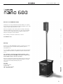 3
3
-
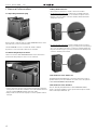 4
4
-
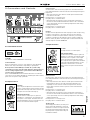 5
5
-
 6
6
-
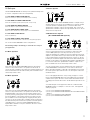 7
7
-
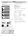 8
8
-
 9
9
-
 10
10
-
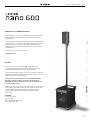 11
11
-
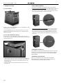 12
12
-
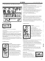 13
13
-
 14
14
-
 15
15
-
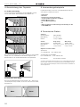 16
16
-
 17
17
-
 18
18
-
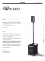 19
19
-
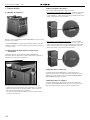 20
20
-
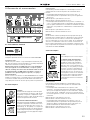 21
21
-
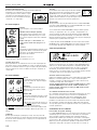 22
22
-
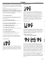 23
23
-
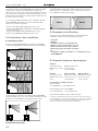 24
24
-
 25
25
-
 26
26
-
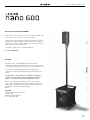 27
27
-
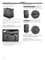 28
28
-
 29
29
-
 30
30
-
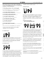 31
31
-
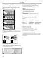 32
32
-
 33
33
-
 34
34
-
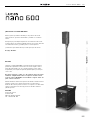 35
35
-
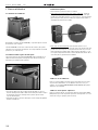 36
36
-
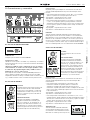 37
37
-
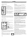 38
38
-
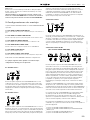 39
39
-
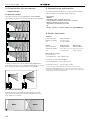 40
40
-
 41
41
-
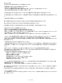 42
42
-
 43
43
-
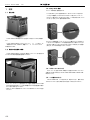 44
44
-
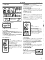 45
45
-
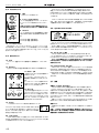 46
46
-
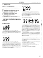 47
47
-
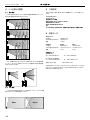 48
48
-
 49
49
-
 50
50
-
 51
51
-
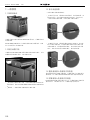 52
52
-
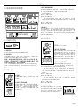 53
53
-
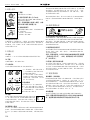 54
54
-
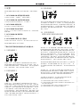 55
55
-
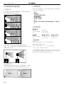 56
56
-
 57
57
-
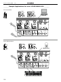 58
58
-
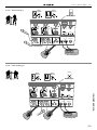 59
59
-
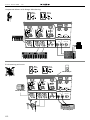 60
60
-
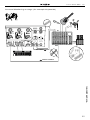 61
61
-
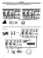 62
62
-
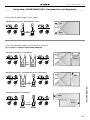 63
63
-
 64
64


HK Audio Lucas nano 600 Manual de usuario
- Categoría
- Altavoces de la barra de sonido
- Tipo
- Manual de usuario
en otros idiomas
- français: HK Audio Lucas nano 600 Manuel utilisateur
- italiano: HK Audio Lucas nano 600 Manuale utente
- English: HK Audio Lucas nano 600 User manual
- Deutsch: HK Audio Lucas nano 600 Benutzerhandbuch
- 日本語: HK Audio Lucas nano 600 ユーザーマニュアル
Artículos relacionados
-
HK Audio Lucas Nano 608i Manual de usuario
-
HK Audio LUCAS NANO 300 Manual de usuario
-
HK Audio Lucas Nano 605 FX El manual del propietario
-
-
-
-
-
-