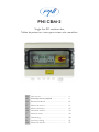
PNI CBM-2 Single Fase DC Combiner Box Manual de usuario
- Tipo
- Manual de usuario

PNI CBM2
Single fase DC combiner box
Tablou de protectie si intrerupere sistem solar monofazic
EN User manual ......................................................... 3
BG Ръководство за употреба ............................. 9
DE Benutzerhandbuch .............................................. 15
ES Manual de usuario ............................................... 21
FR Manuel utilisateur ............................................... 27
HU Használati utasítás .............................................. 33
IT Manuale utente .................................................. 39
NL Handleiding ........................................................ 45
PL Instrukcja obsługi ............................................... 51
RO Manual de utilizare ............................................. 57


3User manual
English
Safety instructions
Please read this manual carefully before installation. Take all the measures
described below for personal and equipment safety.
Warning!
AII the wirings should be performed by a professional
electrician.
Warning!
Operation and wirings must comply with national and local
norms and standards.
Warning!
During the day installation of the photovoltaic modules,
use an opaque material to cover the photovoltaic moduIes,
as they will produce a high voltage that may cause electric
shock.
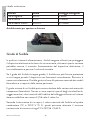
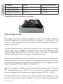
Brief introduction
ln order to reduce the wire connection between PV components and
inverter, to improve the reliability and to be convenient to maintain, the
combiner box is needed generally for large Grid-Connected PV systems.
PNI CBM-2 is specially designed to satisfy this requirement. lt sets up
a complete solution for a PV power generation system with an inverter.
By using a combiner box, the user could combine a certain number of
PV components with the same specification into one PV components
bunch according to the input DC voltage range of the inverter, then
which will be more convenient for the connection of the latter inverter.
lt is strongly recommended that the user should follow all the necessary safety
measures listed in the instructions manual to ensure personal safety and reduce

User manual 4
English
danger.
PNI CBM-2 DC Combiner Box have the below features:
• Protection grade IP65, outdoor installation and operation
• It prevents the components damage from UV, acids, alkali, moisture,
mildew and rats.
• Every string is equipped with DC 1000V 15A Fuse, up to 2 strings could
be accessed at the same time.
• Equipped with DC SPD, either positive pole or negative pole. Lightning
protection.
• 4-Pole DC isolator Switch. The poles are connected in series respectively
by polarity to improve DC withstand voltage.
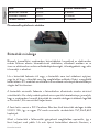
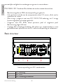
Basic structure

5User manual
English
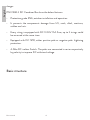
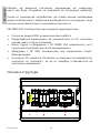
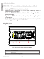
Internal arrangement of DC combiner box
1DC fuse
2DC SPD
3DC isolator switch
4Earthing terminal
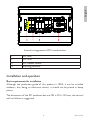
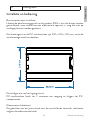
Installation and operation
Basic requirements for installation
Although the protection grade of this product is IP65, it can be installed
outdoors, but, being an electronic device, it should not be placed in damp
places.
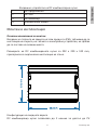
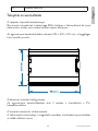
The dimensions of the DC combiner box are 292 x 220 x 120 mm, the vertical
wall installation is suggested.

User manual 6
English
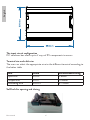
The input circuit configuration
DC combiner box allows up to 2 ways of PV components to access.
Terminal size and cable size
The user can select the appropriate wire to the dierent terminal according to
the below table:
Item Gland Recommended wiring
Input wire PG09 4-8mm
Output wire PG21 13-18mm
Grounding wire PG13.5 6.7-12mm
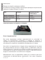
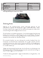
Self-lock for opening and closing

7User manual
English
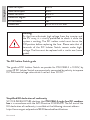
Fuse grade
ln any power system, fuses are used to protect the electronic device from over-
current damage, otherwise, this current may cause the electronic device to be
out of work, overheat, or even fire risk.
If the fuse grade is too large, the fuse can not provide protection or f it is too
small the device will not work normally. Therefore, selecting the right fuse is
needed based on the rating of PV modules and the requirements of relevant
standards.
The minimum grade of a fuse can be calculated by the short-circuiting of
photovoltaic components. If there are no special requirements of local
standards, we suggest the ratings of the fuse and wiring used in the system
need to meet no less than 1.56 times the Isc value.
According to the above description, the rating of the fuse in the DC Combiner
Box is 1000V 15A, so we can get the maximum short-circuit of each PV string
is 15/1.56=9.62A.
Because the fuse is optional according to user needs, so the above situation is
just an example. lf want to match fuse in other grade, users need to check the
instruction above to make sure whether the fuse meets the requirement.
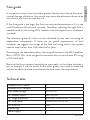
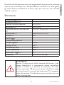
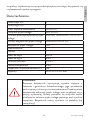
Technical data
Number of DC inputs 2
Number of DC outputs 1
Max. rated voltage 1000V DC
DC isolator switch 32A 1000V
DC surge protection In=20kA, Imax=40kA, 1000V DC
DC fuse holder Imax=30A,1000V DC
DC fuse link 15A
Monitoring /
Power supply /

User manual 8
English
Cable for inputs PG09
Cable for outputs PG21
Glands for earth PG13.5
Protection degree IP65
UV resistance Yes
Dimensions 292 x 220 x 120 mm
Warning!
As the fuse withstands high voltage from the inverter and
the PV array, it is strictly prohibited to check it while the
system is working. The DC isolator switch must be on the
O position before replacing the fuse. Please note that all
terminals of the DC lsolator Switch remain under high-
voltage. The fuse must be replaced with a similar one (same
grade).
The DC lsolator Switch grade
The grade of DC lsolator Switch we provide for PNI CBM-2 is 1000V, by
using 4P DC lsolator Switch are respectively connected by polarity to improve
DC withstand voltage value which is not less than 1000V.
Simplified EU declaration of conformity
SC ONLINESHOP SRL declares that PNI CBM-2 single fase DC combiner
box is in accordance with the LVD Directive 2014/35/EU. The full text of the
EU declaration of conformity is available at the following internet address:
https://www.mypni.eu/products/8530/download/certifications

Ръководство
Български
9
Инструкции за безопасност
Моля, прочетете внимателно това ръководство преди инсталиране.
Вземете всички мерки, описани по-долу, за лична безопасност и
безопасност на оборудването.
Внимание!
ВСИЧКИ кабели трябва да се извършват от
професионален електротехник.
Внимание!
Работата и окабеляването трябва да отговарят на
националните и местните норми и стандарти.
Внимание!
По време на дневния монтаж на фотоволтаичните
модули използвайте непрозрачен материал, за да
покриете фотоволтаичните модули, тъй като те ще
произведат високо напрежение, което може да
причини токов удар.
Кратко въведение
За да се намали кабелната връзка между фотоволтаичните
компоненти и инвертора, да се подобри надеждността и да бъде
удобна за поддръжка, комбинираната кутия е необходима като цяло
за големи фотоволтаични системи, свързани към мрежата.
PNI CBM-2 е специално проектиран да удовлетвори това
изискване. Създава цялостно решение за фотоволтаична система
за генериране на електроенергия с инвертор. Чрез използването
на кутия за комбиниране, потребителят може да комбинира
определен брой фотоволтаични компоненти с една и съща
спецификация в един пакет фотоволтаични компоненти според

Ръководство
Български
10
обхвата на входното постоянно напрежение на инвертора,
което ще бъде по-удобно за свързване на последния инвертор.
Силно се препоръчва потребителят да спазва всички необходими
мерки за безопасност, изброени в ръководството с инструкции, за да
осигури лична безопасност и да намали опасността.
PNI CBM-2 DC Combiner Box има следните характеристики:
• Степен на защита IP65, външен монтаж и работа
• Предотвратява увреждането на компонентите от UV, киселини,
основи, влага, плесен и плъхове.
• Всяка струна е оборудвана с DC 1000V 15A предпазител, до 2
струни могат да бъдат достъпни едновременно.
• Оборудван с DC SPD, положителен или отрицателен полюс.
Мълниезащита.
• 4-полюсен DC изолатор. Полюсите са свързани последователно,
съответно по полярност, за да се подобри устойчивостта на
постоянно напрежение.
Основна структура

Ръководство
Български
11
Вътрешно устройство на DC комбинаторна кутия
1DC предпазител
2DC SPD
3DC изолатор
4Заземителна клема
Монтаж и експлоатация
Основни изисквания за монтаж
Въпреки че степента на защита на този продукт е IP65, той може да се
инсталира на открито, но тъй като е електронно устройство, не трябва
да се поставя на влажни места.
Размерите на DC комбинираната кутия са 292 x 220 x 120 mm,
препоръчва се вертикална инсталация на стена.
Конфигурация на входната верига
DC комбинираща кутия позволява до 2 начина за достъп до PV

Ръководство
Български
12
компоненти.
Размер на клемата и размер на кабела
Потребителят може да избере подходящия проводник към различния
терминал според таблицата по-долу:
Вещ пълнеж Препоръчително
окабеляване
Входен проводник PG09 4-8mm
Изходен проводник PG21 13-18mm
Заземителен
проводник
PG13.5 6.7-12mm
Самозаключване за отваряне и затваряне
Клас предпазител
Във всяка захранваща система предпазителите се използват за
защита на електронното устройство от повреда от свръхток, в
противен случай този ток може да доведе до неработоспособност на
електронното устройство, прегряване или дори риск от пожар.
Ако класът на предпазителя е твърде голям, предпазителят не може
да осигури защита или ако е твърде малък, устройството няма да
работи нормално. Следователно изборът на правилния предпазител е
необходим въз основа на номиналната стойност на фотоволтаичните
модули и изискванията на съответните стандарти.
Минималният клас на предпазител може да се изчисли чрез късо
съединение на фотоволтаични компоненти. Ако няма специални

Ръководство
Български
13
изисквания на местните стандарти, предлагаме номиналните
стойности на предпазителя и окабеляването, използвани в системата,
да отговарят на не по-малко от 1,56 пъти стойността Isc.
Според горното описание, номиналната стойност на предпазителя
в DC комбиниращата кутия е 1000V 15A, така че можем да получим
максималното късо съединение на всеки PV низ от 15/1,56=9,62A.
Тъй като предпазителят не е задължителен според нуждите на
потребителя, така че горната ситуация е само пример. Ако искат
да съпоставят предпазител от друг клас, потребителите трябва да
проверят инструкцията по-горе, за да се уверят дали предпазителят
отговаря на изискването.
Технически данни
Брой DC входове 2
Брой DC изходи 1
Макс. номинално напрежение 1000V DC
DC изолатор 32A 1000V
DC защита от пренапрежение In=20kA, Imax=40kA, 1000V DC
Държач за DC предпазител Imax=30A,1000V DC
DC предпазител 15A
Мониторинг /
Захранване /
Кабел за входове PG09
Кабел за изходи PG21
Жлези за земята PG13.5
Степен на защита IP65
UV устойчивост Yes
Размери 292 x 220 x 120 mm

Ръководство
Български
14
Внимание!
Тъй като предпазителят издържа на високо
напрежение от инвертора и PV масива, е строго
забранено да се проверява, докато системата
работи. Превключвателят на изолатора за постоянен
ток трябва да е в положение Изключено, преди да
смените предпазителя. Моля, имайте предвид, че
всички клеми на превключвателя на DC изолатора
остават под високо напрежение. Предпазителят
трябва да бъде заменен с подобен (същия клас).
Клас на превключвател на изолатора за постоянен ток
Степента на DC lsolator превключвателя, който предоставяме за
PNI CBM-2, е 1000V, като се използва 4P DC lsolator превключвател,
съответно свързани чрез полярност, за да се подобри стойността на
издържаното на DC напрежение, което е не по-малко от 1000V.
Опростена ЕС декларация за съответствие
SC ONLINESHOP SRL декларира, че PNI CBM-2 еднофазна DC
комбинирана кутия е в съответствие с Директива LVD 2014/35/EU.
Пълният текст на ЕС декларацията за съответствие е достъпен на
следния интернет адрес:
hps://www.mypni.eu/products/8530/download/cercaons

Benutzerhandbuch
Deutsche
15
Sicherheitshinweise
Bitte lesen Sie dieses Handbuch vor der Installation sorgfältig durch.
Ergreifen Sie alle nachfolgend beschriebenen Maßnahmen zur Personen- und
Gerätesicherheit.
Warnung!
ALLE Verkabelungen sollten von einem professionellen
Elektriker durchgeführt werden.
Warnung!
Betrieb und Verkabelung müssen den nationalen und lokalen
Normen und Standards entsprechen.
Warnung!
Decken Sie die Photovoltaikmodule während der
Installation der Photovoltaikmodule tagsüber mit einem
undurchsichtigen Material ab, da diese eine hohe Spannung
erzeugen, die einen Stromschlag verursachen kann.
Kurze Einleitung
Um die Kabelverbindung zwischen PV-Komponenten und Wechselrichter zu
reduzieren, die Zuverlässigkeit zu verbessern und die Wartung zu vereinfachen,
wird der Generatoranschlusskasten im Allgemeinen für große netzgekoppelte
PV-Systeme benötigt.
PNI CBM-2 wurde speziell entwickelt, um diese Anforderung zu erfüllen.
Es stellt eine Komplettlösung für eine PV-Stromerzeugungsanlage mit
Wechselrichter bereit. Durch die Verwendung einer Anschlussbox kann
der Benutzer eine bestimmte Anzahl von PV-Komponenten mit derselben
Spezifikation entsprechend dem Eingangs-Gleichspannungsbereich des
Wechselrichters zu einem PV-Komponentenbündel zusammenfassen, was
dann für den Anschluss des letzteren Wechselrichters praktischer ist.

Benutzerhandbuch
Deutsche
16
Es wird dringend empfohlen, dass der Benutzer alle in der Bedienungsanleitung
aufgeführten erforderlichen Sicherheitsmaßnahmen befolgt, um die
persönliche Sicherheit zu gewährleisten und Gefahren zu reduzieren.
Die PNI CBM-2 DC Combiner Box verfügt über die folgenden Funktionen:
• Schutzart IP65, Installation und Betrieb im Freien
• Es verhindert Schäden an den Komponenten durch UV-Strahlung, Säuren,
Laugen, Feuchtigkeit, Schimmel und Ratten.
• Jeder String ist mit einer DC 1000V 15A-Sicherung ausgestattet, so dass
auf bis zu 2 Strings gleichzeitig zugegrien werden kann.
• Ausgestattet mit DC SPD, entweder Pluspol oder Minuspol. Blitzschutz.
• 4-poliger DC-Trennschalter. Die Pole sind entsprechend ihrer Polarität in
Reihe geschaltet, um die Gleichspannungsfestigkeit zu verbessern.
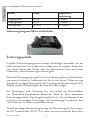
Grundstruktur
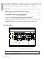
Interne Anordnung des DC-Sammelkastens
1DC-Sicherung
2DC SPD

Benutzerhandbuch
Deutsche
17
3DC-Trennschalter
4Erdungsklemme
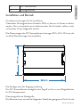
Installation und Betrieb
Grundvoraussetzungen für die Installation
Obwohl der Schutzgrad dieses Produkts IP65 ist, kann es im Freien installiert
werden. Da es sich jedoch um ein elektronisches Gerät handelt, sollte es nicht
an feuchten Orten aufgestellt werden.
Die Abmessungen des DC-Sammelkastens betragen 292 x 220 x 120 mm, die
vertikale Wandmontage wird empfohlen.
Die Konfiguration der Eingangsschaltung
Der DC-Sammelkasten ermöglicht den Zugri auf bis zu zwei Möglichkeiten
für PV-Komponenten.
Klemmengröße und Kabelgröße
Der Benutzer kann anhand der folgenden Tabelle den geeigneten Draht für die

Benutzerhandbuch
Deutsche
18
verschiedenen Klemmen auswählen:
Artikel Gland Empfohlene
Verkabelung
Eingangskabel PG09 4-8mm
Ausgangskabel PG21 13-18mm
Erdungskabel PG13.5 6.7-12mm
Selbstverriegelung zum Önen und Schließen
Sicherungsqualität
In jedem Stromversorgungssystem werden Sicherungen verwendet, um das
elektronische Gerät vor Schäden durch Überstrom zu schützen. Andernfalls
kann dieser Strom dazu führen, dass das elektronische Gerät nicht mehr
funktioniert, überhitzt oder sogar in Brand gerät.
Wenn der Sicherungsgrad zu groß ist, kann die Sicherung keinen Schutz bieten,
und wenn er zu klein ist, funktioniert das Gerät nicht normal. Daher muss die
Auswahl der richtigen Sicherung auf der Grundlage der Nennleistung der PV-
Module und der Anforderungen relevanter Normen erfolgen.
Der Mindestgrad einer Sicherung lässt sich anhand des Kurzschließens
von Photovoltaik-Komponenten berechnen. Wenn es keine besonderen
Anforderungen lokaler Normen gibt, empfehlen wir, dass die Nennwerte der
im System verwendeten Sicherungen und Verkabelungen mindestens dem
1,56-fachen des Isc-Werts entsprechen müssen.
Gemäß der obigen Beschreibung beträgt die Nennleistung der Sicherung in
der DC Combiner Box 1000 V 15 A, sodass wir einen maximalen Kurzschluss

Benutzerhandbuch
Deutsche
19
jedes PV-Strangs von 15/1,56 = 9,62 A erhalten können.
Da die Sicherung je nach Benutzerbedarf optional ist, handelt es sich bei der
obigen Situation nur um ein Beispiel. Wenn Sie eine Sicherung einer anderen
Güteklasse verwenden möchten, müssen Benutzer die obige Anleitung prüfen,
um sicherzustellen, dass die Sicherung die Anforderungen erfüllt.
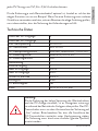
Technische Daten
Anzahl der DC-Eingänge 2
Anzahl der DC-Ausgänge 1
Max. Nennspannung 1000V DC
DC-Trennschalter 32A 1000V
DC-Überspannungsschutz In=20kA, Imax=40kA, 1000V DC
DC-Sicherungshalter Imax=30A,1000V DC
DC-Sicherungseinsatz 15A
Überwachung /
Stromversorgung /
Kabel für Eingänge PG09
Kabel für Ausgänge PG21
Drüsen für die Erde PG13.5
Schutzgrad IP65
UV-Beständigkeit Yes
Maße 292 x 220 x 120 mm
Warnung!
Da die Sicherung der hohen Spannung des Wechselrichters
und der PV-Anlage standhält, ist es strengstens untersagt,
sie während des Betriebs der Anlage zu überprüfen. Der DC-
Trennschalter muss vor dem Austauschen der Sicherung auf
„Aus“ stehen. Bitte beachten Sie, dass alle Anschlüsse des
DC-Trennschalters weiterhin unter Hochspannung stehen.
Die Sicherung muss durch eine ähnliche (gleiche Qualität)
ersetzt werden..

Benutzerhandbuch
Deutsche
20
Die Klasse des DC-Isolatorschalters
Der Grad des DC-Isolatorschalters, den wir für PNI CBM-2 bereitstellen,
beträgt 1000 V. Durch die Verwendung von 4P-DC-Isolatorschaltern werden
die Schalter jeweils entsprechend der Polarität verbunden, um den DC-
Spannungswert zu verbessern, der nicht weniger als 1000 V beträgt.
Vereinfachte EU-Konformitätserklärung
SC ONLINESHOP SRL erklärt, dass der einphasige DC-Sammelkasten PNI
CBM-2 der LVD-Richtlinie 2014/35/EU entspricht. Der vollständige Text der
EU-Konformitätserklärung ist unter der folgenden Internetadresse verfügbar:
https://www.mypni.eu/products/8530/download/certifications

Manual de usuario
Español
21
Instrucciones de seguridad
Lea atentamente este manual antes de la instalación. Tome todas las medidas
descritas a continuación para la seguridad personal y del equipo.
¡Advertencia!
TODO el cableado debe ser realizado por un electricista
profesional.
¡Advertencia!
La operación y el cableado deben cumplir con las normas y
estándares nacionales y locales..
¡Advertencia!
Durante el día de instalación de los módulos fotovoltaicos,
utilice un material opaco para cubrir los módulos fotovoltaicos,
ya que producirán un alto voltaje que puede causar descargas
eléctricas..
Breve introducción
Con el fin de reducir la conexión de cables entre los componentes fotovoltaicos
y el inversor, mejorar la confiabilidad y facilitar el mantenimiento, la caja
combinadora generalmente se necesita para grandes sistemas fotovoltaicos
conectados a la red.
PNI CBM-2 está especialmente diseñado para satisfacer este requisito.
Establece una solución completa para un sistema de generación de energía
fotovoltaica con un inversor. Mediante el uso de una caja combinadora, el
usuario puede combinar una cierta cantidad de componentes fotovoltaicos con
la misma especificación en un grupo de componentes fotovoltaicos de acuerdo
con el rango de voltaje de CC de entrada del inversor, entonces cuál será más
conveniente para la conexión de este último inversor.

Manual de usuario
Español
22
Se recomienda encarecidamente que el usuario siga todas las medidas de
seguridad necesarias enumeradas en el manual de instrucciones para garantizar
la seguridad personal y reducir el peligro.
PNI CBM-2 DC Combiner Box tiene las siguientes características:
• Grado de protección IP65, instalación y funcionamiento en exteriores
• Previene el daño de los componentes por UV, ácidos, álcalis, humedad,
moho y ratas.
• Cada cadena está equipada con un fusible DC 1000V 15A, se puede
acceder a hasta 2 cadenas al mismo tiempo.
• Equipado con DC SPD, ya sea de polo positivo o de polo negativo.
Protección contra rayos.
• Interruptor aislador de CC de 4 polos. Los polos están conectados en serie
respectivamente por polaridad para mejorar el voltaje soportado de CC.
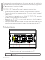
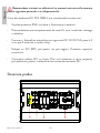
Estructura basica
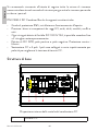
Disposición interna de la caja combinadora de CC
1fusible de CC

Manual de usuario
Español
23
2DC SPD
3 interruptor de aislamiento de CC
4 Terminal de puesta a tierra
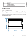
Instalación y operación
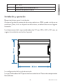
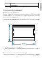
Requisitos básicos para la instalación.
Aunque el grado de protección de este producto es IP65, puede instalarse en
exteriores, pero, al ser un dispositivo electrónico, no debe colocarse en lugares
húmedos.
Las dimensiones de la caja combinadora de CC son 292 x 220 x 120 mm, se
sugiere la instalación vertical en la pared.
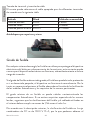
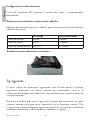
La configuración del circuito de entrada
La caja combinadora de CC permite el acceso de hasta 2 formas de componentes
fotovoltaicos.

Manual de usuario
Español
24
Tamaño de terminal y tamaño de cable
El usuario puede seleccionar el cable apropiado para los diferentes terminales
de acuerdo con la siguiente tabla:
Artículo Gland Cableado recomendado
Cable de entrada PG09 4-8mm
Cable de salida PG21 13-18mm
Cable de puesta a tierra PG13.5 6.7-12mm
Autobloqueo para apertura y cierre
Grado de fusible
En cualquier sistema de energía, los fusibles se utilizan para proteger el dispositivo
electrónico del daño por sobrecorriente, de lo contrario, esta corriente puede
causar que el dispositivo electrónico no funcione, sobrecalentamiento o incluso
riesgo de incendio.
Si el grado del fusible es demasiado grande, el fusible no puede brindar protección
o si es demasiado pequeño, el dispositivo no funcionará normalmente. Por lo
tanto, es necesario seleccionar el fusible adecuado en función de la clasificación
de los módulos fotovoltaicos y los requisitos de las normas pertinentes.
El grado mínimo de un fusible se puede calcular cortocircuitando los
componentes fotovoltaicos. Si no existen requisitos especiales de las normas
locales, sugerimos que las clasificaciones del fusible y el cableado utilizados en
el sistema deben cumplir no menos de 1,56 veces el valor Isc.
De acuerdo con la descripción anterior, la clasificación del fusible en la caja
combinadora de CC es de 1000 V 15 A, por lo que podemos obtener el

Manual de usuario
Español
25
cortocircuito máximo de cada cadena fotovoltaica de 15/1,56 = 9,62 A.
Debido a que el fusible es opcional según las necesidades del usuario, la situación
anterior es solo un ejemplo. Si desea combinar el fusible en otro grado, los
usuarios deben verificar las instrucciones anteriores para asegurarse de que el
fusible cumpla con el requisito.
Datos técnicos
Número de entradas de CC 2
Número de salidas de CC 1
máx. tensión nominal 1000V DC
interruptor de aislamiento de CC 32A 1000V
Protección contra sobretensiones de
CC In=20kA, Imax=40kA, 1000V DC
Portafusibles de CC Imax=30A,1000V DC
Fusible de CC 15A
Supervisión /
Fuente de alimentación /
Cable para entradas PG09
Cable para salidas PG21
Glándulas para tierra PG13.5
Grado de protección IP65
Resistencia a los rayos ultravioleta Yes
Dimensiones 292 x 220 x 120 mm
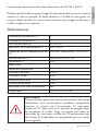
¡Advertencia!
Como el fusible soporta alta tensión del inversor y del campo
fotovoltaico, está estrictamente prohibido comprobarlo
mientras el sistema está funcionando. El interruptor
aislador de CC debe estar en la posición de apagado antes
de reemplazar el fusible. Tenga en cuenta que todos los
terminales del interruptor aislador de CC permanecen bajo
alto voltaje. El fusible debe ser reemplazado por uno similar
(mismo grado).

Manual de usuario
Español
26
El grado del interruptor aislador de CC
El grado del interruptor aislador de CC que proporcionamos para PNI CBM-2
es de 1000 V, mediante el uso del interruptor aislador de CC 4P se conectan
respectivamente por polaridad para mejorar el valor de voltaje soportado de
CC, que no es inferior a 1000 V..
Declaración UE de conformidad simplificada
SC ONLINESHOP SRL declara que la caja combinadora de CC monofásica
PNI CBM-2 cumple con la Directiva LVD 2014/35/EU. El texto completo de
la declaración UE de conformidad está disponible en la siguiente dirección de
Internet:
https://www.mypni.eu/products/8530/download/certifications

Manuel utilisateur
Français
27
Consignes de sécurité
Veuillez lire attentivement ce manuel avant l’installation. Prendre toutes les
mesures décrites ci-dessous pour la sécurité des personnes et des équipements.
Avertissement!
TOUS les câblages doivent être eectués par un électricien
professionnel.
Avertissement!
Le fonctionnement et les câblages doivent être conformes
aux normes et standards nationaux et locaux.
Avertissement!
Pendant la journée d’installation des modules photovoltaïques,
utilisez un matériau opaque pour recouvrir les modules
photovoltaïques, car ils produiront une haute tension pouvant
provoquer un choc électrique.
Courte introduction
Afin de réduire la connexion filaire entre les composants PV et l’onduleur,
d’améliorer la fiabilité et d’être pratique à entretenir, le boîtier de combinaison
est généralement nécessaire pour les grands systèmes PV connectés au réseau.
Le PNI CBM-2 est spécialement conçu pour répondre à cette exigence. Il
met en place une solution complète pour un système de production d’énergie
PV avec un onduleur. En utilisant un boîtier de combinaison, l’utilisateur peut
combiner un certain nombre de composants PV avec la même spécification
en un groupe de composants PV en fonction de la plage de tension continue
d’entrée de l’onduleur, ce qui sera plus pratique pour la connexion de ce dernier
onduleur.
Il est fortement recommandé à l’utilisateur de suivre toutes les mesures de
sécurité nécessaires répertoriées dans le manuel d’instructions pour assurer la

Manuel utilisateur
Français
28
sécurité personnelle et réduire les risques.
PNI CBM-2 DC Combiner Box a les caractéristiques ci-dessous:
• Degré de protection IP65, installation et fonctionnement à l’extérieur
• Il empêche les composants d’être endommagés par les UV, les acides, les
alcalis, l’humidité, la moisissure et les rats.
• Chaque chaîne est équipée d’un fusible DC 1000V 15A, jusqu’à 2 chaînes
sont accessibles en même temps.
• Équipé d’un parafoudre DC, soit au pôle positif, soit au pôle négatif.
Protection contre la foudre.
• Interrupteur d’isolement CC à 4 pôles. Les pôles sont connectés en série
respectivement par polarité pour améliorer la tension de tenue en courant
continu.
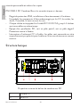
Structure basique
Disposition interne du boîtier de combinaison DC
1Fusible CC
2SPD CC

Manuel utilisateur
Français
29
3Interrupteur sectionneur CC
4Borne de terre
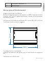
Mise en place et fonctionnement
Exigences de base pour l’installation
Bien que le degré de protection de ce produit soit IP65, il peut être installé à
l’extérieur, mais, étant un appareil électronique, il ne doit pas être placé dans
des endroits humides.
Les dimensions de la boîte de combinaison DC sont de 292 x 220 x 120 mm,
l’installation murale verticale est suggérée.
La configuration du circuit d’entrée
Le boîtier de combinaison DC permet jusqu’à 2 voies d’accès aux composants
PV.
Taille de borne et taille de câble

Manuel utilisateur
Français
30
L’utilisateur peut sélectionner le fil approprié à la borne diérente selon le
tableau ci-dessous:
Article Gland Câblage recommandé
Fil d'entrée PG09 4-8mm
Fil de sortie PG21 13-18mm
Fil de mise à la terre PG13.5 6.7-12mm
Verrouillage automatique pour l’ouverture et la fermeture
Catégorie de fusible
Dans tout système d’alimentation, des fusibles sont utilisés pour protéger
l’appareil électronique contre les dommages causés par les surintensités, sinon,
ce courant peut entraîner une panne, une surchaue ou même un risque
d’incendie de l’appareil électronique.
Si la qualité du fusible est trop grande, le fusible ne peut pas fournir de
protection ou s’il est trop petit, l’appareil ne fonctionnera pas normalement.
Par conséquent, il est nécessaire de choisir le bon fusible en fonction de la
puissance nominale des modules PV et des exigences des normes pertinentes.
Le grade minimum d’un fusible peut être calculé par la mise en court-circuit
des composants photovoltaïques. S’il n’y a pas d’exigences particulières des
normes locales, nous suggérons que les valeurs nominales du fusible et du
câblage utilisés dans le système doivent respecter au moins 1,56 fois la valeur
Isc.
Selon la description ci-dessus, la valeur nominale du fusible dans le DC
Combiner Box est de 1000V 15A, nous pouvons donc obtenir le court-circuit

Manuel utilisateur
Français
31
maximum de chaque chaîne PV est de 15/1,56 = 9,62A.
Étant donné que le fusible est facultatif en fonction des besoins de l’utilisateur,
la situation ci-dessus n’est qu’un exemple. Si vous voulez faire correspondre le
fusible dans une autre classe, les utilisateurs doivent vérifier les instructions ci-
dessus pour s’assurer que le fusible répond à l’exigence.
Données techniques
Nombre d'entrées CC 2
Nombre de sorties CC 1
Max. tension nominale 1000V DC
Interrupteur sectionneur CC 32A 1000V
Protection contre les surtensions
CC In=20kA, Imax=40kA, 1000V DC
Porte-fusible CC Imax=30A,1000V DC
Fusible CC 15A
Surveillance /
Source de courant /
Câble pour entrées PG09
Câble pour les sorties PG21
Glandes pour la terre PG13.5
Degré de protection IP65
Résistance aux UV Yes
Dimensions 292 x 220 x 120 mm
Avertissement!
Comme le fusible résiste à la haute tension de l’onduleur et
du générateur photovoltaïque, il est strictement interdit de le
vérifier pendant que le système fonctionne. Le sectionneur
DC doit être sur la position O avant de remplacer le fusible.
Veuillez noter que toutes les bornes de l’interrupteur de
l’isolateur CC restent sous haute tension. Le fusible doit être
remplacé par un fusible similaire (même calibre).

Manuel utilisateur
Français
32
La catégorie de commutateur d’isolateur de CC
La qualité du commutateur d’isolateur CC que nous fournissons pour PNI
CBM-2 est de 1000 V, en utilisant un commutateur d’isolateur CC 4P sont
respectivement connectés par polarité pour améliorer la valeur de tension de
tenue CC qui n’est pas inférieure à 1000 V.
Déclaration de conformité UE simplifiée
SC ONLINESHOP SRL déclare que le boîtier de combinaison DC monophasé
PNI CBM-2 est conforme à la directive LVD 2014/35/EU. Le texte complet
de la déclaration UE de conformité est disponible à l’adresse Internet suivante:
https://www.mypni.eu/products/8530/download/certifications

Használati utasítás
Magyar
33
Biztonsági utasítások
Kérjük, a telepítés előtt figyelmesen olvassa el ezt a kézikönyvet. Tegye meg
az alábbiakban leírt összes intézkedést a személyes és a berendezés biztonsága
érdekében.
Figyelem!
MINDEN huzalozást szakképzett villanyszerelőnek kell
elvégeznie.
Figyelem!
A működésnek és a vezetékeknek meg kell felelniük a nemzeti
és helyi normáknak és szabványoknak.
Figyelem!
A napelemes modulok napközbeni beszerelése során
használjon átlátszatlan anyagot a fotovoltaikus modulok
lefedésére, mivel azok magas feszültséget termelnek, ami
áramütést okozhat..
Rövid bemutatkozás
A PV-komponensek és az inverter közötti vezetékes kapcsolat csökkentése, a
megbízhatóság javítása és a kényelmes karbantartás érdekében általában nagy,
hálózatra kapcsolt PV-rendszerekhez van szükség a kombinálódobozra.
A PNI CBM-2 kifejezetten ennek a követelménynek a kielégítésére készült.
Komplett megoldást állít fel egy inverteres PV áramtermelő rendszerhez.
A kombinálódoboz használatával a felhasználó az inverter bemeneti
egyenfeszültség-tartományának megfelelően bizonyos számú, azonos
specifikációjú PV komponenst egyesíthet egy PV komponens csokorba, így
melyik lesz kényelmesebb az utóbbi inverter csatlakoztatásához.
Erősen ajánlott, hogy a felhasználó kövesse a használati útmutatóban felsorolt
összes szükséges biztonsági intézkedést a személyes biztonság és a veszély

Használati utasítás
Magyar
34
csökkentése érdekében.
A PNI CBM-2 DC kombinálódoboz az alábbi jellemzőkkel rendelkezik:
• Védettség IP65, kültéri telepítés és üzemeltetés
• Megakadályozza az összetevők UV, savak, lúgok, nedvesség, penész és
patkányok okozta károsodását.
• Minden húr DC 1000V 15A biztosítékkal van felszerelve, így akár 2 húr is
elérhető egyszerre.
• Egyenáramú SPD-vel szerelve, akár pozitív, akár negatív pólusú.
Villámvédelem.
• 4 pólusú DC leválasztó kapcsoló. A pólusok sorba vannak kötve a polaritás
szerint, hogy javítsák az egyenáramú ellenállást.
Alapfelépítés
A DC kombináló doboz belső elrendezése
1DC biztosíték
2DC SPD
3DC leválasztó kapcsoló

Használati utasítás
Magyar
35
4Földelő terminál
Telepítés és üzemeltetés
A telepítés alapvető követelményei
Bár ennek a terméknek a védettsége IP65, kültéren is felszerelhető, de mivel
elektronikai eszköz, nem szabad nedves helyen elhelyezni.
Az egyenáramú kombináló doboz méretei 292 x 220 x 120 mm, a függőleges
falra szerelés javasolt.
A bemeneti áramkör konfigurációja
Az egyenáramú kombinálódoboz akár 2 módon is hozzáférhet a PV-
komponensekhez.
A kivezetés mérete és a kábel mérete
A felhasználó kiválaszthatja a megfelelő vezetéket a különböző terminálokhoz
az alábbi táblázat szerint
:

Használati utasítás
Magyar
36
Tétel Gland Javasolt vezetékezés
Bemeneti vezeték PG09 4-8mm
Kimeneti vezeték PG21 13-18mm
Földelő vezeték PG13.5 6.7-12mm
Önreteszelő nyitáshoz és záráshoz
Biztosíték minősége
Bármely áramellátási rendszerben biztosítékokat használnak az elektronikus
eszköz túláram okozta károsodásának védelmére, ellenkező esetben ez az
áram az elektronikus eszköz működésképtelenségét, túlmelegedését vagy akár
tűzveszélyt is okozhat.
Ha a biztosíték fokozata túl nagy, a biztosíték nem tud védelmet nyújtani,
vagy ha túl kicsi, a készülék nem fog megfelelően működni. Ezért a megfelelő
biztosítékot a PV-modulok minősítése és a vonatkozó szabványok követelményei
alapján kell kiválasztani.
A biztosíték minimális fokozata a fotovoltaikus alkatrészek rövidre zárásával
számítható ki. Ha a helyi szabványoknak nincs speciális követelménye, javasoljuk,
hogy a rendszerben használt biztosíték és vezeték névleges értékének legalább
az Isc érték 1,56-szorosát kell teljesítenie.
A fenti leírás szerint a DC Combiner Box-ban lévő biztosíték névleges értéke
1000V 15A, így az egyes PV-sorok maximális rövidzárlatát 15/1,56=9,62A
kaphatjuk.
Mivel a biztosíték a felhasználói igényeknek megfelelően opcionális, így a
fenti helyzet csak példa. Ha más típusú biztosítékot akarnak illeszteni, a

Használati utasítás
Magyar
37
felhasználóknak ellenőrizniük kell a fenti utasítást, hogy megbizonyosodjanak
arról, hogy a biztosíték megfelel-e a követelményeknek..
Műszaki adatok
DC bemenetek száma 2
DC kimenetek száma 1
Max. névleges feszültség 1000V DC
DC leválasztó kapcsoló 32A 1000V
DC túlfeszültség védelem In=20kA, Imax=40kA, 1000V DC
DC biztosítéktartó Imax=30A,1000V DC
DC biztosíték link 15A
Monitoring /
Tápegység /
Kábel a bemenetekhez PG09
Kábel a kimenetekhez PG21
Mirigyek a földnek PG13.5
Védelmi fokozat IP65
UV ellenállás Igen
Méretek 292 x 220 x 120 mm
Figyelem!
Mivel a biztosíték ellenáll az inverter és a PV-tömb
nagyfeszültségének, szigorúan tilos ellenőrizni a rendszer
működése közben. A biztosíték cseréje előtt a DC leválasztó
kapcsolónak Ki állásban kell lennie. Kérjük, vegye figyelembe,
hogy a DC lsolator kapcsoló összes kapcsa nagyfeszültség
alatt marad. A biztosítékot ki kell cserélni egy hasonlóra
(azonos minőségű).
A DC lsolator Switch fokozat
A PNI CBM-2-hez biztosított DC lsolator Switch fokozata 1000 V, a 4P DC

Használati utasítás
Magyar
38
lsolator Switchek polaritással vannak összekötve, hogy javítsák az egyenáramú
feszültségállóságot, amely nem kevesebb, mint 1000 V.
Egyszerűsített EU megfelelőségi nyilatkozat
Az SC ONLINESHOP SRL kijelenti, hogy a PNI CBM-2 egyfázisú
egyenáramú kombinálódoboz megfelel a 2014/35/EU LVD-irányelvnek. Az
EU-megfelelőségi nyilatkozat teljes szövege az alábbi internetcímen érhető el:
https://www.mypni.eu/products/8530/download/certifications

Manuale dell’utente
Italiano
39
Istruzioni di sicurezza
Si prega di leggere attentamente questo manuale prima dell’installazione.
Adottare tutte le misure descritte di seguito per la sicurezza personale e delle
apparecchiature.
Avvertimento!
TUTTI i cablaggi devono essere eseguiti da un elettricista
professionista.
Avvertimento!
Il funzionamento e il cablaggio devono essere conformi alle
norme e agli standard nazionali e locali.
Avvertimento!
Durante l’installazione diurna dei moduli fotovoltaici,
utilizzare un materiale opaco per coprire i moduli fotovoltaici,
in quanto produrranno un’alta tensione che potrebbe causare
scosse elettriche.
Breve introduzione
Al fine di ridurre la connessione via cavo tra i componenti FV e l’inverter,
per migliorare l’adabilità e per essere conveniente da mantenere, il quadro
combinatore è generalmente necessario per i grandi sistemi FV connessi alla
rete.
PNI CBM-2 è appositamente progettato per soddisfare questo requisito. Crea
una soluzione completa per un sistema di generazione di energia fotovoltaica
con un inverter. Utilizzando una scatola combinatrice, l’utente può combinare
un certo numero di componenti fotovoltaici con le stesse specifiche in un
unico gruppo di componenti fotovoltaici in base all’intervallo di tensione CC
in ingresso dell’inverter, che sarà quindi più conveniente per il collegamento di
quest’ultimo inverter.

Manuale dell’utente
Italiano
40
Si raccomanda vivamente all’utente di seguire tutte le misure di sicurezza
necessarie elencate nel manuale di istruzioni per garantire la sicurezza personale
e ridurre i pericoli.
PNI CBM-2 DC Combiner Box ha le seguenti caratteristiche:
• Grado di protezione IP65, installazione e funzionamento all’aperto
• Previene i danni ai componenti da raggi UV, acidi, alcali, umidità, mua e
ratti.
• Ogni stringa è dotata di fusibile DC 1000V 15A, è possibile accedere fino
a 2 stringhe contemporaneamente.
• Dotato di DC SPD, polo positivo o polo negativo. Protezione contro i
fulmini.
• Sezionatore CC a 4 poli. I poli sono collegati in serie rispettivamente per
polarità per migliorare la tensione di tenuta CC.
Struttura di base
Disposizione interna della scatola del combinatore CC
1Fusibile CC

Manuale dell’utente
Italiano
41
2CC SPD
3Sezionatore CC
4 Terminale di messa a terra
Installazione e funzionamento
Requisiti di base per l’installazione
Sebbene il grado di protezione di questo prodotto sia IP65, può essere
installato all’aperto, ma, trattandosi di un dispositivo elettronico, non deve
essere collocato in luoghi umidi.
Le dimensioni del quadro elettrico DC sono 292 x 220 x 120 mm, si consiglia
l’installazione a parete verticale.
La configurazione del circuito di ingresso
La scatola combinatrice CC consente l’accesso a un massimo di 2 modi di
componenti fotovoltaici.
Dimensione del terminale e dimensione del cavo
L’utente può selezionare il filo appropriato per il terminale diverso in base alla

Manuale dell’utente
Italiano
42
tabella sottostante:
Articolo Gland Cablaggio consigliato
Filo di ingresso PG09 4-8mm
Filo di uscita PG21 13-18mm
Filo di messa a terra PG13.5 6.7-12mm
Autobloccante per apertura e chiusura
Grado di fusibile
ln qualsiasi sistema di alimentazione, i fusibili vengono utilizzati per proteggere
il dispositivo elettronico da danni da sovracorrente, altrimenti questa corrente
potrebbe causare il mancato funzionamento del dispositivo elettronico, il
surriscaldamento o persino il rischio di incendio.
Se il grado del fusibile è troppo grande, il fusibile non può fornire protezione
o se è troppo piccolo il dispositivo non funzionerà normalmente. Pertanto, è
necessario selezionare il fusibile giusto in base alla potenza nominale dei moduli
fotovoltaici e ai requisiti delle norme pertinenti.
Il grado minimo di un fusibile può essere calcolato dalla cortocircuitazione dei
componenti fotovoltaici. Se non ci sono requisiti speciali degli standard locali,
suggeriamo che i valori nominali del fusibile e del cablaggio utilizzati nel sistema
devono soddisfare non meno di 1,56 volte il valore Isc.
Secondo la descrizione di cui sopra, il valore nominale del fusibile nel quadro
combinatore CC è 1000 V 15 A, quindi possiamo ottenere il massimo
cortocircuito di ciascuna stringa FV è 15/1,56 = 9,62 A.

Manuale dell’utente
Italiano
43
Perché il fusibile è opzionale in base alle esigenze dell’utente, quindi la situazione
sopra è solo un esempio. Se si desidera abbinare il fusibile in un altro grado,
gli utenti devono controllare le istruzioni sopra per assicurarsi che il fusibile
soddisfi i requisiti.
Dati tecnici
Numero di ingressi CC 2
Numero di uscite CC 1
Massimo. tensione nominale 1000V DC
Sezionatore CC 32A 1000V
Protezione contro le sovratensioni
CC In=20kA, Imax=40kA, 1000V DC
Portafusibile CC Imax=30A,1000V DC
Fusibile CC 15A
Monitoraggio /
Alimentazione elettrica /
Cavo per ingressi PG09
Cavo per uscite PG21
Ghiandole per terra PG13.5
Grado di protezione IP65
Resistenza ai raggi UV Si
Dimensioni 292 x 220 x 120 mm
Avvertimento!
Poiché il fusibile resiste all’alta tensione dell’inverter e del
campo fotovoltaico, è severamente vietato controllarlo
mentre il sistema è in funzione. Il sezionatore CC deve
essere in posizione O prima di sostituire il fusibile. Si prega
di notare che tutti i terminali del sezionatore CC rimangono
sotto alta tensione. Il fusibile deve essere sostituito con uno
simile (stesso grado).

Manuale dell’utente
Italiano
44
Il grado di interruttore dell’isolatore CC
Il grado di interruttore isolante CC che forniamo per PNI CBM-2 è 1000
V, utilizzando gli interruttori isolanti CC 4P collegati rispettivamente dalla
polarità per migliorare il valore della tensione di tenuta CC che non è inferiore
a 1000 V.
Dichiarazione di conformità UE semplificata
SC ONLINESHOP SRL dichiara che il quadro combinatore CC monofase
PNI CBM-2 è conforme alla Direttiva LVD 2014/35/UE. Il testo completo
della dichiarazione di conformità UE è disponibile al seguente indirizzo Internet:
https://www.mypni.eu/products/8530/download/certifications

Gebruikershandleiding
Nederlands
45
Veiligheidsinstructies
Lees deze handleiding zorgvuldig door voordat u met de installatie begint.
Neem alle hieronder beschreven maatregelen voor de veiligheid van personen
en apparatuur.
Waarschuwing!
ALLE bedrading moet worden uitgevoerd door een
professionele elektricien.
Waarschuwing!
De werking en bedrading moeten voldoen aan de nationale
en lokale normen en standaarden.
Waarschuwing!
Gebruik tijdens de daginstallatie van de fotovoltaïsche
modules ondoorzichtig materiaal om de fotovoltaïsche
modules te bedekken, aangezien deze een hoge spanning
produceren die een elektrische schok kan veroorzaken.
Korte introductie
Om de kabelverbinding tussen PV-componenten en omvormer te verminderen,
de betrouwbaarheid te verbeteren en gemakkelijk te onderhouden, is de
combinerbox over het algemeen nodig voor grote netgekoppelde PV-systemen.
PNI CBM-2 is speciaal ontworpen om aan deze eis te voldoen. Het zet een
complete oplossing op voor een PV-stroomopwekkingssysteem met een
omvormer. Door een combinerbox te gebruiken, kan de gebruiker een bepaald
aantal PV-componenten met dezelfde specificatie combineren tot één bundel
PV-componenten volgens het DC-ingangsspanningsbereik van de omvormer,
wat handiger zal zijn voor de aansluiting van de laatstgenoemde omvormer.
Het wordt ten zeerste aanbevolen dat de gebruiker alle noodzakelijke
veiligheidsmaatregelen volgt die in de gebruiksaanwijzing staan vermeld om

Gebruikershandleiding
Nederlands
46
persoonlijke veiligheid te waarborgen en gevaar te verminderen.
PNI CBM-2 DC Combiner Box hebben de onderstaande kenmerken:
• Beschermingsklasse IP65, buitenopstelling en gebruik
• Het voorkomt schade aan de componenten door UV, zuren, alkali, vocht,
meeldauw en ratten.
• Elke string is uitgerust met een DC 1000V 15A-zekering, tot 2 strings
kunnen tegelijkertijd worden gebruikt.
• Uitgerust met DC SPD, ofwel positieve pool of negatieve pool.
Bescherming tegen bliksem.
• 4-polige DC-scheidingsschakelaar. De polen zijn respectievelijk in serie
geschakeld door polariteit om de DC-weerstandsspanning te verbeteren.
Basis structuur
Interne opstelling van DC-combinerbox
1 DC-zekering
2DC SPD
3DC-scheidingsschakelaar

Gebruikershandleiding
Nederlands
47
4Aardingsklem
Installatie en bediening
Basisvereisten voor installatie
Hoewel de beschermingsgraad van dit product IP65 is, kan het buiten worden
geïnstalleerd, maar omdat het een elektronisch apparaat is, mag het niet op
vochtige plaatsen worden geplaatst.
De afmetingen van de DC-combinerbox zijn 292 x 220 x 120 mm, verticale
wandmontage wordt aanbevolen.
De configuratie van het ingangscircuit
DC-combinerbox biedt tot 2 manieren om toegang te krijgen tot PV-
componenten.
Klemmaat en kabelmaat
De gebruiker kan de juiste draad naar de verschillende terminals selecteren
volgens de onderstaande tabel:

Gebruikershandleiding
Nederlands
48
Item Gland Aanbevolen bedrading
Ingangsdraad PG09 4-8mm
Uitgang draad PG21 13-18mm
Aarddraad PG13.5 6.7-12mm
Zelfvergrendeling voor openen en sluiten
Zekering klasse
Zekering In elk voedingssysteem worden zekeringen gebruikt om het
elektronische apparaat te beschermen tegen overstroomschade, anders
kan deze stroom ervoor zorgen dat het elektronische apparaat zonder werk,
oververhitting of zelfs brandgevaar komt te staan.
Als de kwaliteit van de zekering te groot is, kan de zekering geen bescherming
bieden of als hij te klein is, zal het apparaat niet normaal werken. Daarom is
het selecteren van de juiste zekering nodig op basis van de classificatie van PV-
modules en de vereisten van relevante normen.
De minimale kwaliteit van een zekering kan worden berekend door het
kortsluiten van fotovoltaïsche componenten. Als er geen speciale vereisten
van lokale normen zijn, raden we aan dat de classificaties van de zekering en
bedrading die in het systeem worden gebruikt, niet minder dan 1,56 keer de
Isc-waarde moeten zijn.
Volgens de bovenstaande beschrijving is de classificatie van de zekering in de
DC Combiner Box 1000V 15A, dus we kunnen de maximale kortsluiting van
elke PV-reeks krijgen van 15/1,56=9,62A.
Omdat de zekering optioneel is volgens de behoeften van de gebruiker, is de

Gebruikershandleiding
Nederlands
49
bovenstaande situatie slechts een voorbeeld. Als u een zekering in een andere
klasse wilt matchen, moeten gebruikers de bovenstaande instructie controleren
om er zeker van te zijn dat de zekering aan de vereiste voldoet.
Technische data
Aantal DC-ingangen 2
Aantal DC-uitgangen 1
Max. nominale spanning 1000V DC
DC-scheidingsschakelaar 32A 1000V
DC-overspanningsbeveiliging In=20kA, Imax=40kA, 1000V DC
DC-zekeringhouder Imax=30A,1000V DC
DC-zekeringkoppeling 15A
Toezicht houden /
Stroomvoorziening /
Kabel voor ingangen PG09
Kabel voor uitgangen PG21
Klieren voor aarde PG13.5
Beschermingsgraad IP65
UV-bestendigheid Ja
Dimensies 292 x 220 x 120 mm
Waarschuwing!
Aangezien de zekering bestand is tegen hoge spanning van de
omvormer en de PV-generator, is het ten strengste verboden
om deze te controleren terwijl het systeem in werking is. De
DC-isolatieschakelaar moet in de uit-stand staan voordat u de
zekering vervangt. Houd er rekening mee dat alle klemmen
van de DC Isolator Switch onder hoogspanning blijven staan.
De zekering moet worden vervangen door een soortgelijke
(dezelfde kwaliteit).

Gebruikershandleiding
Nederlands
50
De DC isolator Switch-kwaliteit
De kwaliteit van de DC-isolatorschakelaar die we leveren voor PNI CBM-2 is
1000V, door gebruik te maken van 4P DC-isolatorschakelaars die respectievelijk
zijn verbonden door polariteit om de DC-weerstandsspanningswaarde te
verbeteren die niet minder is dan 1000V.
Vereenvoudigde EU-conformiteitsverklaring
SC ONLINESHOP SRL verklaart dat de PNI CBM-2 enkelfasige DC-
combinerbox in overeenstemming is met de laagspanningsrichtlijn 2014/35/
EU. De volledige tekst van de EU-conformiteitsverklaring is beschikbaar op
het volgende internetadres:
https://www.mypni.eu/products/8530/download/certifications

Instrukcja obsługi
Polskie
51
Instrukcje bezpieczeństwa
Prosimy o uważne zapoznanie się z niniejszą instrukcją przed instalacją. Podejmij
wszystkie opisane poniżej środki bezpieczeństwa osobistego i sprzętowego.
Ostrzeżenie!
WSZYSTKIE okablowanie powinno być wykonane przez
profesjonalnego elektryka.
Ostrzeżenie!
Obsługa i okablowanie muszą być zgodne z krajowymi i
lokalnymi normami i standardami.
Ostrzeżenie!
Podczas dziennej instalacji modułów fotowoltaicznych należy
użyć nieprzezroczystego materiału do zakrycia modułów
fotowoltaicznych, ponieważ będą one wytwarzać wysokie
napięcie, które może spowodować porażenie prądem.
Krótkie wprowadzenie
Aby zredukować liczbę połączeń przewodowych między komponentami
fotowoltaicznymi a falownikiem, poprawić niezawodność i ułatwić konserwację,
skrzynka połączeniowa jest zwykle potrzebna w przypadku dużych systemów
fotowoltaicznych podłączonych do sieci.
PNI CBM-2 został specjalnie zaprojektowany, aby spełnić to wymaganie.
Tworzy kompletne rozwiązanie dla systemu wytwarzania energii fotowoltaicznej
z falownikiem. Używając skrzynki połączeniowej, użytkownik może połączyć
pewną liczbę komponentów fotowoltaicznych o tej samej specyfikacji w
jedną wiązkę komponentów fotowoltaicznych zgodnie z zakresem napięcia
wejściowego DC falownika, co będzie wygodniejsze dla podłączenia drugiego
falownika.
Zdecydowanie zaleca się, aby użytkownik przestrzegał wszystkich niezbędnych

Instrukcja obsługi
Polskie
52
środków bezpieczeństwa wymienionych w instrukcji obsługi, aby zapewnić
bezpieczeństwo osobiste i zmniejszyć niebezpieczeństwo.
PNI CBM-2 DC Combiner Box ma poniższe funkcje:
• Stopień ochrony IP65, instalacja i eksploatacja na zewnątrz
• Zapobiega uszkodzeniu komponentów przez promieniowanie UV, kwasy,
zasady, wilgoć, pleśń i szczury.
• Każdy łańcuch jest wyposażony w bezpiecznik DC 1000 V 15 A, co pozwala
na równoczesny dostęp do 2 ciągów.
• Wyposażony w DC SPD, biegun dodatni lub biegun ujemny. Ochrona
przed piorunami.
• 4-biegunowy odłącznik prądu stałego. Bieguny są połączone szeregowo
odpowiednio według biegunowości, aby poprawić napięcie wytrzymywane
prądem stałym.
Podstawowa struktura
Wewnętrzny układ skrzynki przyłączeniowej DC
1 Bezpiecznik prądu stałego

Instrukcja obsługi
Polskie
53
2DC SPD
3 Odłącznik prądu stałego
4Zacisk uziemiający
Instalacja i obsługa
Podstawowe wymagania dotyczące instalacji
Chociaż stopień ochrony tego produktu to IP65, można go instalować na
zewnątrz, ale jako urządzenie elektroniczne nie należy go umieszczać w
wilgotnych miejscach.
Wymiary skrzynki przyłączeniowej DC to 292 x 220 x 120 mm, sugerowany
jest pionowy montaż na ścianie.
Konfiguracja obwodu wejściowego
Skrzynka przyłączeniowa DC umożliwia dostęp do komponentów
fotowoltaicznych na 2 sposoby.
Rozmiar terminala i rozmiar kabla
Użytkownik może wybrać odpowiedni przewód do innego zacisku zgodnie z
poniższą tabelą:

Instrukcja obsługi
Polskie
54
Przedmiot Gland Zalecane okablowanie
Przewód wejściowy PG09 4-8mm
Przewód wyjściowy PG21 13-18mm
Przewód uziemiający PG13.5 6.7-12mm
Samoblokujący do otwierania i zamykania
Klasa bezpiecznika
W każdym systemie zasilania bezpieczniki służą do ochrony urządzenia
elektronicznego przed uszkodzeniem przez przetężenie, w przeciwnym razie
prąd ten może spowodować awarię urządzenia elektronicznego, przegrzanie, a
nawet ryzyko pożaru.
Jeśli klasa bezpiecznika jest zbyt duża, bezpiecznik nie może zapewnić ochrony
lub jest zbyt mały, urządzenie nie będzie działać normalnie. Dlatego wybór
odpowiedniego bezpiecznika jest konieczny w oparciu o parametry znamionowe
modułów fotowoltaicznych i wymagania odpowiednich norm.
Minimalny stopień bezpiecznika można obliczyć na podstawie zwarcia elementów
fotowoltaicznych. Jeśli nie ma specjalnych wymagań lokalnych norm, zalecamy,
aby wartości znamionowe bezpiecznika i okablowania zastosowanego w systemie
były co najmniej 1,56 razy większe od wartości Isc.
Zgodnie z powyższym opisem wartość znamionowa bezpiecznika w skrzynce
DC Combiner Box wynosi 1000 V 15 A, więc możemy uzyskać maksymalne
zwarcie każdego łańcucha fotowoltaicznego na poziomie 15/1,56 = 9,62 A.
Ponieważ bezpiecznik jest opcjonalny w zależności od potrzeb użytkownika, więc
powyższa sytuacja jest tylko przykładem. Jeśli chcesz dopasować bezpiecznik

Instrukcja obsługi
Polskie
55
innej klasy, użytkownicy muszą sprawdzić powyższą instrukcję, aby upewnić się,
czy bezpiecznik spełnia wymagania.
Dane techniczne
Liczba wejść DC 2
Liczba wyjść DC 1
Maks. napięcie znamionowe 1000V DC
Odłącznik prądu stałego 32A 1000V
Ochrona przeciwprzepięciowa prądu
stałego In=20kA, Imax=40kA, 1000V DC
Uchwyt bezpiecznika prądu stałego Imax=30A,1000V DC
Bezpiecznik prądu stałego 15A
Monitorowanie /
Zasilacz /
Kabel do wejść PG09
Kabel do wyjść PG21
Gruczoły do ziemi PG13.5
Poziom zabezpieczeń IP65
Odporność na promieniowanie UV Tak
Wymiary 292 x 220 x 120 mm
Ostrzeżenie!
Ponieważ bezpiecznik wytrzymuje wysokie napięcie z
falownika i generatora fotowoltaicznego, jego sprawdzanie
podczas pracy systemu jest surowo zabronione. Przed wymianą
bezpiecznika odłącznik prądu stałego musi znajdować się w
pozycji wyłączonej. Należy pamiętać, że wszystkie zaciski
przełącznika izolatora prądu stałego pozostają pod wysokim
napięciem. Bezpiecznik należy wymienić na podobny (tej
samej klasy).

Instrukcja obsługi
Polskie
56
Klasa przełącznika izolatora DC
Stopień przełącznika izolatora DC, który zapewniamy dla PNI CBM-2, wynosi
1000 V, przy użyciu przełącznika izolatora 4P DC są odpowiednio połączone
biegunowo, aby poprawić wartość napięcia wytrzymywanego DC, która jest
nie mniejsza niż 1000 V.
Uproszczona deklaracja zgodności UE
SC ONLINESHOP SRL oświadcza, że jednofazowa skrzynka przyłączeniowa
prądu stałego PNI CBM-2 jest zgodna z dyrektywą LVD 2014/35/UE. Pełny
tekst deklaracji zgodności UE jest dostępny pod następującym adresem
internetowym:
https://www.mypni.eu/products/8530/download/certifications

Manual de utilizare
Romana
57
Instructiuni de siguranta
Va rugam sa cititi cu atentie acest manual inainte de instalare. Luati toate
masurile descrise mai jos pentru siguranta personala si a echipamentului.
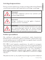
Avertizare!
Toate conexiunile si cablajele trebuie efectuate de un
electrician profesionist.
Avertizare!
Utilizarea, instalarea si conexiunile trebuie sa respecte
normele si standardele nationale si locale.
Avertizare!
Daca instalati modulele fotovoltaice pe timp de zi, utilizati
un material opac pentru a le acoperi, deoarece acestea vor
produce o tensiune inalta care poate provoca socuri electrice.
Scurta introducere
Pentru a reduce conexiunile prin cablu dintre componentele fotovoltaice si
invertor, pentru a imbunatati fiabilitatea si pentru a fi mai usor de intretinut,
cutia de combinare este necesara in general pentru sistemele fotovoltaice de
dimensiuni mari conectate la retea.
PNI CBM-2 este special conceput pentru a satisface aceasta cerinta. Aceasta
cutie de combinare creeaza o solutie completa pentru un sistem fotovoltaic de
generare a energiei cu invertor.
Folosind o cutie de combinare, utilizatorul poate combina in functie de intervalul
de tensiune DC de intrare a invertorului un anumit numar de componente
fotovoltaice cu aceleasi specificatii intr-un singur grup de componente.

Manual de utilizare
Romana
58
Recomandam insistent ca utilizatorul sa urmeze toate masurile necesare
pentru siguranta personala si a echipamentului.
Cutia de combinare DC PNI CBM-2 are urmatoarele caracteristici:
• Grad de protectie IP65, instalare si functionare la exterior.
• Previne deteriorarea componentelor de raze UV, acizi, umiditate, mucegai
si sobolani.
• Fiecare sir fotovoltaic este echipat cu siguranta DC 1000V 15A; pana la 2
siruri pot fi accesate in acelasi timp.
• Echipat cu DC SPD, pol pozitiv sau pol negativ. Protectie impotriva
trasnetului.
• Comutator izolator DC cu 4 pini. Pinii sunt conectati in serie, respectiv
prin polaritate, pentru a imbunatati tensiunea de rezistenta DC.
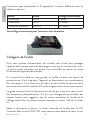
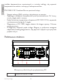
Descriere produs

Manual de utilizare
Romana
59
1Siguranta DC
2SPD DC
3Comutator izolator DC
4Terminal de impamantare
Instalare si utilizare
Cerinte de baza pentru instalare
Desi gradul de protectie al acestui produs este IP65, acesta poate fi instalat in
exterior, insa, fiind un dispozitiv electronic, nu trebuie amplasat in locuri umede.
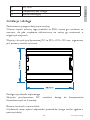
Dimensiunile cutiei de combinare sunt 292 x 220 x 120 mm. Se recomanda
montarea pe perete vertical.

Manual de utilizare
Romana
60
Configuratia circuitului de intrare
Cutia de combinare DC permite 2 moduri de acces a componentelor
fotovoltaice.
Dimensiunea terminalelor si dimensiunea cablurilor
Selectati dimensiunea potrivita a cablului pentru un anumit terminal conform
tabelului de mai jos:
Presetupa Cablu recomandat
Cablu de intrare PG09 4-8mm
Cablu de iesire PG21 13-18mm
Cablu de impamantare PG13.5 6.7-12mm
Autoblocare pentru deschidere si inchidere
Tip siguranta
In orice sistem de alimentare, sigurantele sunt utilizate pentru a proteja
dispozitivul electronic de daune cauzate de supracurent, cum ar fi
nefunctionarea dispozitivului electronic, supraincalzirea sau scurtcircuitarea cu
riscul de incendiu.
Daca are o valoare prea mare, siguranta nu poate oferi protectie sau daca
valoarea acesteia este prea mica, dispozitivul nu va functiona normal. Prin
urmare, este necesara alegerea sigurantei potrivite in functie de clasificarea
modulelor fotovoltaice si de cerintele standardelor in vigoare.

Manual de utilizare
Romana
61
Valoarea minima a unei sigurante poate fi calculata prin scurtcircuitarea
componentelor fotovoltaice. Daca nu exista cerinte speciale impuse de
standardele locale, va sugeram ca valorile nominale ale sigurantei si cablurilor
utilizate in sistemul fotovoltaic sa fie nu mai putin de 1,56 ori valoarea Isc.
Conform descrierii de mai sus, valoarea nominala a sigurantei din cutia PNI
CBM-2 este 1000V 15A, astfel incat sa putem obtine un scurtcircuit maxim al
fiecarui sir fotovoltaic: 15/1,56=9,62A.
Deoarece alegerea sigurantei este in functie de nevoile utilizatorului, situatia de
mai sus este doar un exemplu. Daca doriti sa folositi o siguranta de alta calitate,
trebuie sa verificati instructiunile de mai sus pentru a va asigura ca siguranta
indeplineste cerintele.
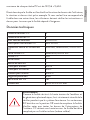
Specificatii tehnice
Numarul de intrari DC 2
Numarul de iesiri DC 1
Tensiune nominala maxima 1000V DC
Comutator izolator DC 32A 1000V
Protectie la supratensiune DC In=20kA, Imax=40kA, 1000V DC
Suport siguranta DC Imax=30A,1000V DC
Legatura de siguranta DC 15A
Monitorizare /
Alimentare electrica /
Cablu pentru intrari PG09
Cablu pentru iesiri PG21
Presetupa pentru impamantare PG13.5
Grad de protectie IP65
Rezistenta UV Yes
Dimensiuni 292 x 220 x 120 mm

Manual de utilizare
Romana
62
Avertizare!
Deoarece siguranta este supusa tensiunii inalte de la invertor
si panourile fotovoltaice, este strict interzis sa umblati la ea
in timp ce sistemul functioneaza. Intrerupatorul izolator DC
trebuie sa fie in pozitia Oprit inainte de a inlocui siguranta.
Va rugam sa retineti ca toate terminalele intrerupatorului
izolatorului DC raman sub tensiune inalta. Siguranta trebuie
inlocuita cu una similara (de aceeasi valoare).
Intrerupatorul izolator DC
Valoarea intrerupatorului izolator DC pe care il oferim pentru PNI CBM-2 este
de 1000 V. Prin utilizarea comutatorului izolator DC 4P, pinii sunt conectati
prin polaritate pentru a imbunatati valoarea tensiunii de rezistenta DC care nu
este mai mica de 1000 V.
Declaratie UE de conformitate simplificata
SC ONLINESHOP SRL declara ca Tablou PNI CBM-2 de protectie si
intrerupere sistem solar monofazic este in conformitate cu Directiva LVD
2014/35/EU. Textul integral al declaratiei UE de conformitate este disponibil
la urmatoarea adresa de internet:
https://www.mypni.eu/products/8530/download/certifications


-
 1
1
-
 2
2
-
 3
3
-
 4
4
-
 5
5
-
 6
6
-
 7
7
-
 8
8
-
 9
9
-
 10
10
-
 11
11
-
 12
12
-
 13
13
-
 14
14
-
 15
15
-
 16
16
-
 17
17
-
 18
18
-
 19
19
-
 20
20
-
 21
21
-
 22
22
-
 23
23
-
 24
24
-
 25
25
-
 26
26
-
 27
27
-
 28
28
-
 29
29
-
 30
30
-
 31
31
-
 32
32
-
 33
33
-
 34
34
-
 35
35
-
 36
36
-
 37
37
-
 38
38
-
 39
39
-
 40
40
-
 41
41
-
 42
42
-
 43
43
-
 44
44
-
 45
45
-
 46
46
-
 47
47
-
 48
48
-
 49
49
-
 50
50
-
 51
51
-
 52
52
-
 53
53
-
 54
54
-
 55
55
-
 56
56
-
 57
57
-
 58
58
-
 59
59
-
 60
60
-
 61
61
-
 62
62
-
 63
63
-
 64
64


PNI CBM-2 Single Fase DC Combiner Box Manual de usuario
- Tipo
- Manual de usuario
en otros idiomas
- français: PNI CBM-2 Single Fase DC Combiner Box Manuel utilisateur
- italiano: PNI CBM-2 Single Fase DC Combiner Box Manuale utente
- Deutsch: PNI CBM-2 Single Fase DC Combiner Box Benutzerhandbuch
- Nederlands: PNI CBM-2 Single Fase DC Combiner Box Handleiding
- polski: PNI CBM-2 Single Fase DC Combiner Box Instrukcja obsługi
Artículos relacionados
-
PNI E650VA Manual de usuario
-
PNI L3000W Manual de usuario
-
PNI Escort HP 9700 Guía del usuario
-
PNI Clementine 8428BT Manual de usuario
-
PNI 8550BT Manual de usuario
-
PNI IP575 Manual de usuario
-
-
PNI H01 Manual de usuario
-