
DANBY PRODUCTS LIMITED, ONTARIO, CANADA N1H 6Z9
DANBY PRODUCTS INC., FINDLAY, OHIO, USA 45840
OWNER’S MANUAL
MANUEL DU PROPRIÉTAIRE
MANUAL DEL PROPIETARIO
www.Danby.com
THROUGH-THE-WALL AIR CONDITIONER
Owner’s Manual.............................1 - 11
CLIMATISEUR MURAL
Manual du propriétaire.................12 - 22
AIRE ACONDICIONADO DE PARED
Manual del propietario..................23 - 33
2019.12.11
MODEL • MODÈLE • MODELO
DPTA090HEB1WDB
DPTA120HEB1WDB
DPTA150HEB1WDB

Welcome
Welcome to the Danby family. We are proud of our quality products and we believe in
dependable service. We suggest that you read this owner’s manual before plugging in your new
appliance as it contains important operation information, safety information, troubleshooting and
maintenance tips to ensure the reliability and longevity of your appliance.
Visit www.Danby.com to access self service tools, FAQs and much more. For additional assistance
call 1-800-263-2629.
Note the information below; you will need this information to obtain service under warranty.
You must provide the original purchase receipt to validate your warranty and receive service.
Model Number: _________________________________________________
Serial Number: _________________________________________________
Date of Purchase: _______________________________________________
Need Help?
Before you call for service, here are a few things you can do to help us serve you better.
Read this owner’s manual:
It contains instructions to help you use and maintain your appliance properly.
If you receive a damaged appliance:
Immediately contact the retailer or builder that sold you the appliance.
Save time and money:
Check the troubleshooting section at the end of this manual before calling. This section
will help you solve common problems that may occur.
1-800-26- Danby
(1-800-263-2629)
1

Important Safety Information
READ AND FOLLOW ALL SAFETY INSTRUCTIONS
SAVE THESE INSTRUCTIONS!
ELECTRICAL REQUIREMENTS
All wiring must comply with local and national
codes and must be installed by a qualifi ed
electrician. Check the available power supply and
resolve any wiring problems before installing and
operating this appliance.
This 230 V appliance may be used in any properly
wired, general purpose household receptacle.
The rating plate located on the right side of the
appliance just above the power cord contains
electrical and other technical data.
SAFETY INSTRUCTIONS
This appliance is not intended for use by persons,
including children, with reduced physical, sensory
or mental capabilities or lack of experience and
knowledge, unless they have been given supervision
or instruction concerning use of the appliance by a
person responsible for their safety.
Children should be supervised to ensure that they
do not play with the appliance.
Do not install the appliance where leakage of
combustible gas is suspected.
POWER CORD INSTRUCTIONS
The power supply cord contains a current device
that senses damage to the power cord. To test the
power supply cord:
1. Press the TEST button on the power supply cord.
The RESET button will click and pop out.
2. Press the RESET button until it clicks into place.
3. The power supply cord is now supplying
electricity to the appliance.
Do not use this device to turn the appliance on or
off. Ensure that the RESET button is pushed in for
correct operation. The power supply cord must be
replaced if it fails to reset when the TEST button is
pushed.
2
GROUNDING INSTRUCTIONS
This appliance must be grounded. Grounding
reduces the risk of electrical shock by providing an
escape wire for the electrical current.
This appliance has a cord that has a grounding
wire with a 3-prong plug. The power cord must be
plugged into an outlet that is properly grounded.
If the outlet is a 2-prong wall outlet, it must be
replaced with a properly grounded 3-prong wall
outlet.
WARNING - Improper use of the grounding
plug can result in a risk of electric shock.
Consult a qualifi ed electrician or service agent
if the grounding instructions are not completely
understood, or if doubt exists as to whether the
appliance is properly grounded.
Do not connect your appliance to extension
cords or together with another appliance in the
same wall outlet. Do not splice the power cord.
Do not under any circumstances cut or remove the
third ground prong from the power cord. Do not
use extension cords or ungrounded (two prongs)
adapters.
If the power supply cord is damaged, it must be
replaced by the manufacturer, its service agent or
similar qualifi ed person in order to avoid hazard.

INSTALLATION INSTRUCTIONS
3
DIMENSIONS
This appliance is 42 inches (106.7 cm) wide, 16
inches (40.8 cm) high and 23.9 inches (60.6 cm)
deep.
WALL SLEEVE
All wall sleeves used to install the air conditioner
must be in good structural condition and have a
rear grille that securely attaches to the sleeve or the
fl ange of the sleeve to secure the appliance.
Install the wall sleeve according to the wall sleeve
installation instructions. When installing the sleeve
make certain there is nothing within 20 inches (50.8
cm) of the back of the appliance that would interfere
with heat radiation and exhaust air fl ow.
INSTALLATION
1. Remove the front panel. Pull out from the bottom
to release it from the tabs and then lift up.
2. Remove the shipping screw from the vent door.
3. Rotate the vent control lever to either open or
close the vent door. When the vent control lever
is set to “close”, only the air inside the room is
circulated. When the vent control lever is set to
“open”, outdoor air will be drawn into the room.
This can reduce heating or cooling effi ciency.
4. Lift the appliance and slide it into the wall sleeve
until it is set fi rmly against the front wall of the
sleeve and secure with four screws through the
fl ange holes.
5. Reinstall the front panel. Place the tabs over the
top rail and push inward at the bottom until the
panel snaps into place.
1
2
3
4
4
5

INSTALLATION INSTRUCTIONS
4
DIP SWITCHES
Dip switch controls are located behind the front
panel through an opening below the control panel.
Remove the front panel to access the dip switches.
Dip switches are accessible without opening the
control box.
The appliance should be unplugged before making
adjustments to the dip switches.
DIP SWITCH CONFIGURATIONS
See the table below for dip switch confi gurations and functions.
UP(ON)
DOWN(OFF)
1 2 3 4 1 2 3 4
S
1
S2
S
3
S
4
S5
S6
S7
S8
X
S
9
A0-
A3
1 2 1 2 3 4
S11
Wall thermostat type
Load delay for 3 seconds
Heating type
Temperature display type
Control type
Setpoint limit 1
Setpoint limit 2
Fan CON/CYC for heating
Fan CON/CYC for cooling
Low temp. Protection
Number UP (ON) DOWN (OFF) Remarks
S1 Electric heat only Electric and pump heat Heat pump model
only
S2 Temperature display °F Temperature display °C
S3 Wall thermostat enable Control panel enable
S4*S5 UP*UP: 61°F ~ 86°F (16°C ~ 30°C)
UP*DOWN: 65°F ~ 78°F (18°C ~ 26°C)
DOWN*UP: 63°F ~ 80°F (17°C ~ 27°C)
DOWN*DOWN: 68°F ~ 75°F (20°C ~ 24°C)
Confi guration of S4
and S5 combine to
select set point range
S6 Fan continuous run for heating Fan cycle for heating
S7 Fan continuous run for cooling Fan cycle for cooling
S8 Low temperature protection enable Low temperature protection disable
S9 (S3
UP)
Use some types of wall thermostat Use PTAC other wall thermostat Consult with
sales agent or
manufacturer for
details
S9 (S3
DOWN)
Use control panel only Use control panel or some types of
wall thermostat
Sw11 Load delay for 3 seconds Normal Optional

5
INSTALLATION INSTRUCTIONS
DIP SWITCH CONFIGURATIONS BY PANEL CONTROL
1. Turn off the appliance.
2. Press and hold the increase and decrease buttons at the same time for 3 seconds to activate the dip
switch confi guration by panel control.
3. See the table below for dip switch confi gurations and functions by panel control.
4. The display will show two numbers. The high left number is for dip switches, the low right number is for
functions.
5. Press the increase button to set the dip switches. Press the decrease button to set the functions.
6. Press and hold the increase and decrease buttons at the same time for 3 seconds to confi rm choices.
The appliance will return to regular functioning after 30 seconds with no input.
Note: The LED display window will show “00” when fi rst entering setting mode. Set switches in sequence
one at a time.
Note: To activate front desk control function, set dip switch SW7 to “DOWN(OFF)” and then set the panel
control to “A0”.
Number High (left) Low (right) Remarks
/ 0 1 - by panel control 0 - by dip switches
S1 1 1 - electric heat only 0 - electric and pump heat Heat pump
model only
S2 2 1 - °F display 0 - °C display
S3*S9 3 3 - use control panel or some types of wall thermostat
2 - use some types of wall thermostat
1 - use PTAC other wall thermostat
0 - use control panel
Consult with
sales agent or
manufacturer for
details
S4*S5 4 4 - 62°F ~ 86°F (17°C ~ 30°C)
3 - 61°F ~ 86°F (16°C ~ 30°C)
2 - 65°F ~ 78°F (18°C ~ 26°C)
1 - 63°F ~ 80°F (17°C ~ 27°C)
0 - 68°F ~ 75°F (20°C ~ 24°C)
S6 6 1 - continuous fan for heating 0 - fan cycle for heating Not available
for “use PTAC
other wall
thermostat”
S7 7 1 - continuous fan for cooling 0 - fan cycle for cooling
S8 8 1 - low temperature protection
enable
0 - low temperature protection
disable
Optional
SW7 A 1 - front desk control enable 0 - front desk control disable Optional
Sw11 B 1 - load delay for 3 seconds 0 - normal Optional

6
INSTALLATION INSTRUCTIONS
WALL THERMOSTAT TERMINAL
Note: Using a wall thermostat is optional.
Important: Only trained, qualifi ed personnel
should access the electrical panel on the appliance
and install electrical accessories. Contact a local
electrical contractor, dealer or distributor for
assistance.
Thermostat Wire Routing
Thermostat wire is fi eld supplied. Recommended
wire gauge is 18 to 20 gauge solid thermostat wire.
Note: It is recommended that extra wires are run
to the appliance in case any are damaged during
installation. Thermostat wire should always be
routed around or under, never through the wall
sleeve. The wire should be routed behind the front
panel to the easily accessible terminal connector.
Pull the dip switch to the DOWN(OFF) position.
Insert the wire connector of the wall thermostat
into the relevant terminal according to the different
shapes as shown.
A: Dip switch
B: Terminal
A
B
B
PTAC Other Wall Thermostat
Remove the two screws as shown and take the cover
panel down.
Terminal of PTAC other wall thermostat (MODE A)
FC(L)
FC(N)
LOW-FAN
HI-FAN
4-WAY
HEAT2
HEAT1
COMP
24V(N)
24V(L)
Terminal of PTAC other wall thermostat (MODE B)
LOW-FAN
HI-FAN
4-WAY
HEAT1
COMP
24V(L)
24V(N)
Caution: Failure to follow this caution may result
in equipment damage or improper operation.
Improper wiring may damage the electronics.
Common busing is not permitted. Damage or erratic
operation may result.

FRONT DESK CONTROL
Note: Using the front desk control is optional.
The controller can handle a switch signal from
FC(L) and FC(N) input, called front desk control.
Input must be 24VAC. If the system does not receive
a 24VAC signal it will turn off; otherwise the
appliance runs in normal control.
The dip switch can control the front desk control
feature. If the dip switch is in the down position,
the appliance will turn off, otherwise it will run as
normal.
ADDITIONAL REQUIREMENTS
• Use 4-way terminal for heat pump connection
only.
• Wall thermostat must be heating changeover
4-way valve.
• For thermostats that have only one fan speed
output (on or auto) the fan speed is determined
by how the terminal connector is wired. If
low fan is desired, wire the G output from the
thermostat to (LOW-FAN) on the appliance’s
terminal block. If high fan is desired, wire the
G output from the thermostat to (HI-FAN) on the
appliance’s terminal block.
• The range of set temperature of wall thermostat
must be in consonance with the range of dip
switch setting.
• Wall thermostat must be set the type properly in
consonance with the appliance type; heat pump
or no heat pump.
• If the wall thermostat has only one electrical
heater output, connect the two terminals of
HEAT 1 and HEAT 2, the appliance can operate
two electrical heaters (only if the appliance has
two electrical heaters). Otherwise operate one
electrical heater.
• Do not remove the control panel.
• If the appliance is being controlled by a wall
mounted thermostat, place the provided cover
over the control panel as per the below.
Note: When the display shows “LC” it means the
buttons on the control panel are not available and
the appliance should be controlled by the wall
mounted thermostat that it is connected to.
INSTALLATION INSTRUCTIONS
7
Cette unité est contrôlée par un thermostat mural
This unit is controlled by a wall mounted thermostat

8
OPERATING INSTRUCTIONS
CONTROL PANEL
1. Remote control receiver
2. Display Panel: Displays the set temperature.
When in fan mode, displays the ambient
temperature. To change the temperature scale
being displayed, press and hold the up and
down buttons at the same time for three seconds.
3. Fan Button: Used to set the fan speed. The fan
can be set to low, medium, and high. The lights
will indicate the chosen fan speed.
4. Continuous fan button: In cooling mode, press
to set the fan to run continuously.
5. Increase and decrease buttons: Used to adjust
the set temperature in 1° increments.
6. Mode button: Used to choose the operating
mode. The lights will indicate the chosen mode,
cool, heat or fan.
7. Power button: Used to turn the appliance on or
off.
2
4 7
3
5
6
1
OPERATING MODES
There are three operating modes to choose from.
Press the Mode Button repeatedly to choose the
desired mode. The adjacent indicator light will
illuminate to show which mode has been selected.
• Cool Mode
Choose cool mode to set the cooling function. Use
the up and down buttons to choose the desired
temperature. When cool mode is selected, the fan
speed can be adjusted by pressing the fan button.
• Heat Mode
Choose heat mode to set the heating function. Use
the up and down buttons to choose the desired
temperature.
• Fan Mode
Choose fan mode to run the internal fan without
engaging the cooling function. Press the fan button
repeatedly to choose the fan speed, low, med or
high.

9
AIR FILTER
The air fi lter should be cleaned approximately every
2 weeks. The air fi lter may require more frequent
cleaning if there is signifi cant dander or fur in the
air.
The air fi lter is located behind the front intake grill.
Grasp the fi lter by the center and pull up and out.
Use a vacuum cleaner with a soft brush attachment
to remove any large debris or dust build up from the
air fi lter.
Wash the fi lter in lukewarm, soapy water, below
40°C (104°F), or use a neutral cleaning agent.
Rinse the fi lter with clean water and dry thoroughly
before reinstalling in the appliance.
Note: Do not operate the appliance without the air
fi lter installed.
CARE & MAINTENANCE
CLEANING
To avoid possible electric shock, ensure that the
appliance is unplugged before performing any
cleaning or maintenance.
The outside of the appliance can be wiped clean
with a soft cloth or with a lukewarm, damp cloth if
necessary.
Do not use gasoline, benzene, thinner or any
other chemicals to clean this appliance as these
substances can cause damage to the fi nish and
deformation of plastic parts.
Never pour water directly onto the appliance as this
will cause deterioration of electrical components
and wiring insulation.
ERROR CODES
If any of the below error codes appear on the
display, unplug the appliance and then plug it back
in. If the error code persists, call for service.
AS - room temperature sensor error
ES - evaporator temperature sensor error
CS - condenser temperature sensor error
OS - outside temperature sensor error
HS - exhaust temperature sensor error
LE - wire controller error
LO - room temperature is lower than 0°C / 32°F
HI - room temperature is higher than 37°C / 99°F
FP - low temperature protection
1
2

TROUBLESHOOTING
Danby Consumer Care: 1-800-263-2629
Hours of operation:
Monday to Thursday 8:30 am - 6:00 pm Eastern Standard Time
Friday 8:30 am - 4:00 pm Eastern Standard Time
Information in this manual is subject to change without notice.
PROBLEM POSSIBLE CAUSE
Appliance will not operate • Plug is not fully inserted into the wall outlet
• Blown fuse or circuit breaker
Insuffi cient cooling • Air fi lter is dirty
• Blocked air fl ow
• Appliance size is too small for application
Noise • Inadequate support in window installation
Odors • Formation of mold or mildew on internal wet surfaces
• Place an algaecide tablet in base pan; push the tablet through
the grill on either side of the appliance
Water dripping inside • Appliance is not properly angled to allow water to drain to the
outside
Water dripping outside • On very hot or humid days dripping water from the back of the
appliance is normal
Frost build up • When outdoor temperatures are below 18.3°C (65°F) frost may
form when the appliance is in cooling mode
• Switch the appliance to fan only mode until the frost melts
10

LIMITED IN-HOME APPLIANCE WARRANTY
This quality product is warranted to be free from manufacturer’s defects in material and workmanship, provided that the unit is used under the normal operating
conditions intended by the manufacturer.
This warranty is available only to the person to whom the unit was originally sold by Danby Products Limited (Canada) or Danby Products Inc. (U.S.A.) (hereafter
“Danby”) or by an authorized distributor of Danby, and is non-transferable.
TERMS OF WARRANTY
Plastic parts, are warranted for thirty (30) days only from purchase date, with no extensions provided.
First Year
During the rst twelve (12) months, any functional parts of this product found to be defective, will be repaired or replaced, at warrantor’s
option, at no charge to the ORIGINAL purchaser.
To obtain
Danby reserves the right to limit the boundaries of “In Home Service” to the proximity of an Authorized Service Depot. Any app liance
Service
requiring service outside the limited boundaries of “In Home Service” , it will be the consumer’s responsibility to transport the appliance (at
their own expense) to the original retailer (point of purchase) or a service depot for repair. See “Boundaries of In Home Serv ice” below.
Contact your dealer from whom your unit was purchased, or contact your nearest authorized Danby service depot, where service
must be performed by a qualied service technician.
If service is performed on the units by anyone other than an authorized service depot, or the unit is used for commercial appli cation, all
obligations of Danby under this warranty shall be void.
Boundaries of
If the appliance is installed in a location that is 100 kilometers (62 miles) or more from the nearest service center your unit must be
In Home Service
delivered to the nearest authorized Danby Service Depot, as service must only be performed by a technician qualied and certif ied for
warranty service by Danby. Transportation charges to and from the service location are not protected by this warranty and are t he
responsibility of the purchaser.
Nothing within this warranty shall imply that Danby will be responsible or liable for any spoilage or damage to food or other c ontents of this appliance, whether due
to any defect of the appliance, or its use, whether proper or improper.
EXCLUSIONS
Save as herein provided, Danby, there are no other warranties, conditions, representations or guarantees, express or implied, m ade or intended by Danby or its
authorized distributors and all other warranties, conditions, representations or guarantees, including any warranties, conditio ns, representations or guarantees
under any Sale of Goods Act or like legislation or statue is hereby expressly excluded. Save as herein provided, Danby shall no t be responsible for any damages
to persons or property, including the unit itself, howsoever caused or any consequential damages arising from the malfunction o f the unit and by the purchase of
the unit, the purchaser does hereby agree to indemnify and hold harmless Danby from any claim for damages to persons or propert y caused by the unit.
GENERAL PROVISIONS
No warranty or insurance herein contained or set out shall apply when damage or repair is caused by any of the following:
1) Power failure.
2) Damage in transit or when moving the appliance.
3) Improper power supply such as low voltage, defective house wiring or inadequate fuses.
4) Accident, alteration, abuse or misuse of the appliance such as inadequate air circulation in the room or abnormal operating con ditions
(extremely high or low room temperature).
5) Use for commercial or industrial purposes (ie. If the appliance is not installed in a domestic residence).
6) Fire, water damage, theft, war, riot, hostility, acts of God such as hurricanes, oods etc.
7) Service calls resulting in customer education.
8) Improper Installation (ie. Building-in of a free standing appliance or using an appliance outdoors that is not approved for out door application).
Proof of purchase date will be required for warranty claims; so, please retain bills of sale. In the event warranty service is required, present this document to our
AUTHORIZED SERVICE DEPOT.
Danby Products Limited
PO Box 1778, Guelph, Ontario, Canada N1H 6Z9
Telephone: (519) 837-0920 FAX: (519) 837-0449
Danby Products Inc.
PO Box 669, Findlay, Ohio, U.S.A. 45840
Telephone: (419) 425-8627 FAX: (419) 425-8629
04/09
1-800-263-2629
Warranty Service
In-home
Danby reserves the right to limit the boundaries of “In Home Service” to the proximity of an authorized service
depot. Any appliance requiring service outside the limited boundaries of “In Home Service”, will be the consumer’s
responsibility to transport at their own expense to the original point of purchase or a service depot for repair. If the
appliance is installed in a location that is 100 kilometers (62 miles) or more from the nearest service center, it must
be delivered to the nearest authorized Danby Service Depot by the purchaser.
Transportation charges to and from the service location are not protected by this warranty and are the
responsibility of the purchaser.
During the first twenty four (24) months, any functional parts of this product found to be defective, will be repaired
or replaced, at warrantor’s option, at no charge to the original purchaser.
Contact the dealer where the unit was purchased, or contact the nearest authorized Danby service depot, where
service must be performed by a qualified service technician. If service is performed on the unit by anyone other
than an authorized service depot, all obligations of Danby under this warranty shall be void.
First 24 months
To obtain service
Boundaries of
in-home service
LIMITED “IN HOME” WARRANTY
This quality product is warranted to be free from manufacturer’s defects in material and workmanship, provided that the unit is used
under the normal operating conditions intended by the manufacturer.
This warranty is available only to the person to whom the unit was originally sold by Danby Products Limited (Canada) or Danby
Products Inc. (U.S.A.) (hereafter “Danby”) or by an authorized distributor of Danby, and is non-transferable.
TERMS OF WARRANTY
Plastic parts are warranted for thirty (30) days from the date of purchase, with no extensions provided.
Nothing within this warranty shall imply that Danby will be responsible or liable for any spoilage or damage to food or other
contents of this appliance, whether due to any defect of the appliance, or its use, whether proper or improper.
EXCLUSIONS
Save as herein provided, by Danby, there are no other warranties, conditions, representations or guarantees, express or implied, made
or intended by Danby or its authorized distributors and all other warranties, conditions, representations or guarantees, including any
warranties, conditions, representations or guarantees under any Sale of Goods Act or like legislation or statute is hereby expressly
excluded. Save as herein provided, Danby shall not be responsible for any damages to persons or property, including the unit itself,
howsoever caused or any consequential damages arising from the malfunction of the unit and by the purchase of the unit, the
purchaser does hereby agree to indemnify and hold harmless Danby from any claim for damages to persons or property caused by
the unit.
GENERAL PROVISIONS
No warranty or insurance herein contained or set out shall apply when damage or repair is caused by any of the following:
1) Power failure.
2) Damage in transit or when moving the appliance.
3) Improper power supply such as low voltage, defective house wiring or inadequate fuses.
4) Accident, alteration, abuse or misuse of the appliance such as inadequate air circulation in the room or abnormal operating
conditions (ie. extremely high or low room temperature).
5) Use for commercial or industrial purposes (ie. If the appliance is not installed in a domestic residence).
6) Fire, water damage, theft, war, riot, hostility, acts of God such as hurricanes, floods etc.
7) Service calls resulting in customer education.
8) Improper Installation (ie. Building-in of a free standing appliance or using an appliance outdoors that is not approved for outdoor
application, including but not limited to: garages, patios, porches or anywhere that is not properly insulated or climate controlled).
Proof of purchase date will be required for warranty claims; retain bills of sale. In the event that warranty service is required, present
the proof of purchase to our authorized service depot.
Warranty Service
In Home
Danby Products Limited
PO Box 1778, Guelph, Ontario, Canada N1H 6Z9
Telephone: (519) 837-0920 FAX: (519) 837-0449
Danby Products Inc.
PO Box 669, Findlay, Ohio, U.S.A. 45840
Telephone: (419) 425-8627 FAX: (419) 425-8629
1-800-263-2629
04/17

12
Bienvenue
Bienvenue à la famille Danby. Nous sommes fi ers de la qualité de nos produits et nous croyons
en le service fi able. Nous vous suggérons de lire ce manual d’utilisation avant de brancher
votre nouvel appareil car il contient des informations inportantes sur l’utilisation, la sécurité, le
dépannage et la maintenance, afi n d’assurer la fi abilité et la longévité de votre appareil.
Visitez www.Danby.com pour accéder aux outils d’autoservice, aux FAQ et bien plus encore. Pour
obtenir de l’aide supplémentaire, composez 1-800-263-2629.
Notez les informations ci-dessous; Vous aurez besoin de cette information pour obtenir un
service sous garantie.
Vous devez fournir le reçu d’achat original pour valider votre garantie et recevoir le service.
Numéro de modèle: _____________________________________________
Numéro de serie: _______________________________________________
Date d’achat: __________________________________________________
Besoin d’assistance?
Avant d’appeler pour service, voici quelques choses que vous pouvez faire pour nous
aider à mieux vous servir.
Lire ce manuel du propriétaire:
Il contient des instructions pour vous aider à utiliser et à maintenir votre appareil
correctement.
Si vous recevez un appareil endommagé:
Contactez immédiatement le revendeur ou l’entrepreneur qui vous a vendu l’appareil.
Gagnez du temps et de l’argent:
Avant d’appeler pour service, consultez la section de dépannage à la fi n de ce manuel.
Cette section vous aidera à résoudre les problèmes courants pouvant survenir.
1-800-26- Danby
(1-800-263-2629)

Informations importantes de sécurité
LIRE ET SUIVRE TOUTES LES INSTRUCTIONS DE SÉCURITÉ
13
GARDEZ CES INSTRUCTIONS!
EXIGENCES ÉLECTRIQUES
Tout le câblage doit être conforme aux codes locaux
et nationaux et doit être installé par un électricien
qualifi é. Vérifi ez l’alimentation électrique disponible
et résolvez tous les problèmes de câblage avant
d’installer et d’utiliser cet appareil.
Cet appareil de 230 V peut être utilisé dans un
récipient domestique à usage général bien câblé.
La plaque signalétique située sur le côté droit de
l’appareil juste au-dessus du cordon d’alimentation
contient des données électriques et autres
techniques.
CONSIGNES DE SÉCURITÉ
Cet appareil n’est pas conçu pour être utilisé par
des personnes, y compris des enfants, avec des
capacités physiques, sensorielles ou mentales
réduites ou un manque d’expérience et de
connaissances, sauf si une personne responsable de
leur sécurité a supervisé ou donné des instructions
sur l’utilisation de l’appareil.
Les enfants doivent être surveillés pour s’assurer
qu’ils ne jouent pas avec l’appareil.
N’installez pas l’appareil dans un endroit où une
fuite de gaz combustible est suspectée.
INSTRUCTIONS DU CORDON D’ALIMENTATION
Le cordon d’alimentation contient un dispositif
en cours qui détecte des dommages au cordon
d’alimentation. Pour tester le cordon d’alimentation:
1. Appuyez sur le bouton TEST du cordon
d’alimentation. Le bouton RESET va cliquer et
sortir.
2. Appuyez sur le bouton RESET jusqu’à ce qu’il
s’enclenche.
3. Le cordon d’alimentation fournit maintenant
l’électricité à l’appareil.
N’utilisez pas cet appareil pour allumer ou éteindre
l’appareil. Assurez-vous que le bouton RESET
est enfoncé pour un fonctionnement correct. Le
cordon d’alimentation doit être remplacé s’il ne se
réinitialise pas lorsque vous appuyez sur le bouton
TEST.
INSTRUCTIONS DE MISE À LA TERRE
Cet appareil doit être mis à la terre. La mise à
la terre réduit le risque de choc électrique en
fournissant un fi l d’échappement pour le courant
électrique.
Cet appareil possède un cordon doté d’un fi l de
mise à la terre avec une fi che à 3 broches. Le
cordon d’alimentation doit être branché sur une
prise correctement mise à la terre. Si la sortie
est une prise murale à 2 broches, elle doit être
remplacée par une prise murale à 3 broches
correctement mise à la terre.
ATTENTION - Une utilisation incorrecte de la
fi che de mise à la terre peut entraîner un risque
d’électrocution. Consultez un électricien qualifi é
ou un agent de service si les instructions de mise
à la terre ne sont pas complètement comprises ou
s’il existe un doute quant à savoir si l’appareil est
correctement mis à la terre.
Ne branchez pas votre appareil à des rallonges
ou avec un autre appareil dans la même prise
murale. Ne pas épisser le cordon d’alimentation.
Ne coupez ou retirez en aucun cas la troisième
broche du cordon d’alimentation. N’utilisez pas de
cordons de prolongement ou d’adaptateurs sans
mise à la terre (deux broches).
Si le cordon d’alimentation est endommagé, il doit
être remplacé par le fabricant, son agent de service
ou une personne qualifi ée similaire afi n d’éviter tout
risque.

14
INSTRUCTIONS D’INSTALLATION
DIMENSIONS
Cet appareil mesure 42 pouces (106,7 cm) de
largeur, 16 pouces (40,8 cm) de hauteur et 23,9
pouces (60,6 cm) de profondeur.
DOUILLE MURALE
Tous les manchons muraux utilisés pour installer
le climatiseur doivent être en bon état structurel et
dotés d’une grille arrière qui s’attache solidement
au manchon ou à la bride du manchon pour fi xer
l’appareil.
Installez le manchon mural conformément aux
instructions d’installation du manchon mural.
Lors de l’installation du manchon, assurez-vous
qu’aucun objet situé à moins de 50,8 cm (20
pouces) de l’arrière de l’appareil n’interfère avec le
rayonnement thermique et le fl ux d’air évacué.
INSTALLATION
1. Retirez le panneau avant. Tirez sur le bas pour
le dégager des languettes, puis soulevez-le.
2. Retirez la vis de transport de la porte de
ventilation.
3. Tournez le levier de commande de ventilation
pour ouvrir ou fermer la porte de ventilation.
Lorsque le levier de commande de ventilation est
réglé sur «fermer», seul l’air à l’intérieur de la
pièce circule. Lorsque le levier de commande de
ventilation est réglé sur «ouvert», l’air extérieur
sera aspiré dans la pièce. Cela peut réduire
l’effi cacité du chauffage ou de la climatisation.
4. Soulevez l’appareil et faites-le glisser dans le
manchon mural jusqu’à ce qu’il soit bien en
place contre la paroi avant du manchon, puis
fi xez-le à l’aide de quatre vis insérées dans les
orifi ces de la bride.
5. Réinstallez le panneau avant. Placez les onglets
sur le rail supérieur et poussez vers le bas
jusqu’à ce que le panneau s’enclenche.
1
2
3
4
4
5

INSTRUCTIONS D’INSTALLATION
INTERRUPTEUR DIP
Les commandes du commutateur DIP sont situées
derrière le panneau avant par une ouverture située
sous le panneau de commande. Retirez le panneau
avant pour accéder aux commutateurs DIP.
Les commutateurs DIP sont accessibles sans ouvrir le
boîtier de commande.
L’appareil doit être débranché avant de régler les
commutateurs DIP.
CONFIGURATIONS DE DIP SWITCH
Voir le tableau ci-dessous pour connaître les confi gurations et les fonctions des commutateurs DIP.
UP(ON)
DOWN(OFF)
1 2 3 4 1 2 3 4
S
1
S2
S
3
S
4
S5
S6
S7
S8
X
S
9
A0-
A3
1 2 1 2 3 4
S11
Wall thermostat
type
Load delay for 3 seconds
Heating type
Temperature display type
Control type
Setpoint limit 1
Setpoint limit 2
Fan CON/CYC for heating
Fan CON/CYC for cooling
Low temp. Protection
Nombre UP (ON) DOWN (OFF) Remarques
S1 Chauffage électrique seulement Chaleur électrique et pompe Modèle à pompe à
chaleur uniquement
S2 Affi chage de la température °F Affi chage de la température °C
S3 Activer le thermostat mural Activer le panneau de contrôle
S4*S5 UP*UP: 61°F ~ 86°F (16°C ~ 30°C)
UP*DOWN: 65°F ~ 78°F (18°C ~ 26°C)
DOWN*UP: 63°F ~ 80°F (17°C ~ 27°C)
DOWN*DOWN: 68°F ~ 75°F (20°C ~ 24°C)
La confi guration de S4
et S5 se combine pour
sélectionner la plage de
points de consigne
S6 Fonctionnement continu du
ventilateur pour le chauffage
Cycle du ventilateur pour le
chauffage
S7 Fonctionnement continu du
ventilateur pour le refroidissement
Cycle du ventilateur pour le
refroidissement
S8 Activer la protection contre les
basses températures
Désactiver la protection contre les
basses températures
S9 (S3
UP)
Utilisez certains types de
thermostat mural
Utilisez un autre thermostat mural
PTAC
Consultez l’agent de
vente ou le fabricant
pour plus de détails.
S9 (S3
DOWN)
Utiliser le panneau de contrôle
uniquement
Utilisez le panneau de commande
ou certains types de thermostat
mural
Sw11 Délai de chargement pendant 3
secondes
Normal Optionnel

INSTRUCTIONS D’UTILISATION
CONFIGURATIONS DE DIP SWITCH PAR COMMANDE DE PANNEAU
1. Éteignez l’appareil.
2. Appuyez simultanément sur les boutons d’augmentation et de diminution et maintenez-les enfoncés
pendant 3 secondes pour activer la confi guration du commutateur DIP via le panneau de commande.
3. Voir le tableau ci-dessous pour les confi gurations et les fonctions des commutateurs DIP par panneau
de commande.
4. L’écran affi chera deux nombres. Le nombre en haut à gauche concerne les commutateurs DIP, le
nombre en bas à droite concerne les fonctions.
5. Appuyez sur le bouton d’augmentation pour régler les commutateurs DIP. Appuyez sur le bouton de
diminution pour défi nir les fonctions.
6. Appuyez simultanément sur les boutons d’augmentation et de diminution et maintenez-les enfoncés
pendant 3 secondes pour confi rmer les choix. L’appareil reviendra à fonctionner normalement après 30
secondes sans entrée.
Remarque: la fenêtre d’affi chage à diodes électroluminescentes indique «00» lors du premier passage en
mode de réglage. Placez les commutateurs en séquence, un à la fois.
Remarque: pour activer la fonction de contrôle de la réception, réglez le commutateur DIP SW7 sur
«DOWN (OFF)», puis réglez le contrôle du panneau sur «A0».
Nombre Haut
(gauche)
Bas (droite) Remarques
/ 0 1 - par panneau de contrôle 0 - par commutateurs DIP
S1 1 1 - chauffage électrique
seulement
0 - chaleur électrique et
pompe
Modèle à pompe à
chaleur uniquement
S2 2 1 - affichage en °F 0 - affichage °C
S3*S9 3 3 - utiliser le panneau de commande ou certains types de
thermostat mural
2 - utiliser certains types de thermostat mural
1 - utilisez un autre thermostat mural PTAC
0 - utiliser le panneau de commande
Consultez l’agent
de vente ou le
fabricant pour plus
de détails.
S4*S5 4 4 - 62°F ~ 86°F (17°C ~ 30°C)
3 - 61°F ~ 86°F (16°C ~ 30°C)
2 - 65°F ~ 78°F (18°C ~ 26°C)
1 - 63°F ~ 80°F (17°C ~ 27°C)
0 - 68°F ~ 75°F (20°C ~ 24°C)
S6 6 1 - ventilateur continu pour le
chauffage
0 - cycle du ventilateur pour le
chauffage
Non disponible
pour “utiliser un
autre thermostat
mural PTAC”
S7 7 1 - ventilateur continu pour le
refroidissement
0 - cycle du ventilateur pour le
refroidissement
S8 8 1 - protection contre les basses
températures
0 - désactiver la protection
contre les basses températures
Optionnel
SW7 A 1 - contrôle de la réception
activé
0 - désactiver le contrôle de la
réception
Optionnel
Sw11 B 1 - délai de chargement
pendant 3 secondes
0 - normal Optionnel

17
INSTRUCTIONS D’UTILISATION
TERMINAL DE THERMOSTAT MURAL
Remarque: L’utilisation d’un thermostat mural est
facultative.
Important: Seul le personnel formé et qualifi é doit
accéder au panneau électrique de l’appareil et
installer les accessoires électriques. Contactez un
entrepreneur, revendeur ou distributeur en électricité
local pour obtenir de l’aide.
Routage des fi ls du thermostat
Le fi l du thermostat est fourni sur place. Le calibre
de fi l recommandé est un fi l de thermostat solide de
calibre 18 à 20.
Remarque: Il est recommandé d’acheminer des
câbles supplémentaires vers l’appareil au cas où
ils seraient endommagés pendant l’installation. Le
fi l du thermostat doit toujours être passé autour ou
en dessous, jamais à travers la gaine murale. Le fi l
doit être acheminé derrière le panneau avant vers le
connecteur de terminal facilement accessible.
Tirez le commutateur DIP sur la position BAS (OFF).
Insérez le connecteur de fi l du thermostat mural
dans la borne appropriée selon les différentes
formes, comme indiqué.
A: commutateur dip
B: terminal
A
B
B
PTAC Autre Thermostat Mural
Retirez les deux vis comme indiqué et abaissez le
panneau de protection.
Terminal d’un autre thermostat mural PTAC (MODE A)
FC(L)
FC(N)
LOW-FAN
HI-FAN
4-WAY
HEAT2
HEAT1
COMP
24V(N)
24V(L)
Terminal d’un autre thermostat mural PTAC (MODE B)
LOW-FAN
HI-FAN
4-WAY
HEAT1
COMP
24V(L)
24V(N)
Attention: le non-respect de cette mise en garde
peut entraîner des dégâts matériels ou une
utilisation incorrecte du matériel. Un câblage
incorrect peut endommager les composants
électroniques. Le bus commun n’est pas autorisé.
Des dommages ou un fonctionnement erratique
peuvent en résulter.

COMMANDE DE BUREAU AVANT
Remarque: l’utilisation du commande de bureau
avant est facultative.
Le contrôleur peut gérer un signal de commutation
provenant des entrées FC (L) et FC (N), appelé
contrôle de la réception. L’entrée doit être 24VAC.
Si le système ne reçoit pas de signal 24 VCA, il
s’éteindra; sinon, l’appareil fonctionne en mode de
contrôle normal.
Le commutateur DIP peut contrôler la fonction de
contrôle de la réception. Si le commutateur DIP
est en position basse, l’appareil s’éteindra sinon il
fonctionnera normalement.
EXIGENCES SUPPLÉMENTAIRES
• Utilisez un terminal à 4 voies pour le
raccordement de la pompe à chaleur
uniquement.
• Le thermostat mural doit être une vanne 4 voies
à inversion de chauffage.
• Pour les thermostats qui ont une seule sortie de
vitesse du ventilateur (activée ou automatique),
la vitesse du ventilateur est déterminée par la
manière dont le connecteur de terminal est
câblé. Si vous souhaitez un ventilateur faible,
câblez la sortie G du thermostat à (LOW-FAN)
sur le bornier de l’appareil. Si vous souhaitez un
haut ventilateur, câblez la sortie G du thermostat
à (HI-FAN) sur le bornier de l’appareil.
• La plage de température de consigne du
thermostat mural doit correspondre à la plage
de réglage du commutateur DIP.
• Le thermostat mural doit être réglé correctement
en fonction du type d’appareil; pompe à chaleur
ou pas de pompe à chaleur.
• Si le thermostat mural n’a qu’une sortie de
chauffage électrique, connectez les deux
bornes de HEAT 1 et HEAT 2, l’appareil peut
faire fonctionner deux appareils de chauffage
électriques (uniquement si l’appareil est équipé
de deux appareils de chauffage électriques).
Sinon, utilisez un appareil de chauffage
électrique.
• Ne retirez pas le panneau de commande.
• Si l’appareil est contrôlé par un thermostat
mural, placez le couvercle fourni sur le panneau
de commande comme indiqué ci-dessous.
Remarque: Lorsque l’écran affi che «LC», cela
signifi e que les boutons du panneau de commande
ne sont pas disponibles et que l’appareil doit
être contrôlé par le thermostat mural auquel il est
connecté.
INSTRUCTIONS D’UTILISATION
18
Cette unité est contrôlée par un thermostat mural
This unit is controlled by a wall mounted thermostat

INSTRUCTIONS D’UTILISATION
19
PANNEAU DE CONTRÔLE
1. Panneau d’affi chage: Affi che la température
défi nie. En mode ventilateur, affi che la
température ambiante. Pour modifi er l’échelle
de température affi chée, maintenez enfoncés
les boutons haut et bas en même temps pendant
trois secondes.
2. Bouton du ventilateur: Utilisé pour régler la
vitesse du ventilateur. Le ventilateur peut être
réglé sur bas, moyen et haut. Les voyants
indiqueront la vitesse du ventilateur choisie.
3. Bouton de ventilation continue: en mode de
refroidissement, appuyez pour que le ventilateur
fonctionne en continu.
4. Boutons augmenter et diminuer: Utilisés
pour régler la température de consigne par
incréments de 1°.
5. Bouton Mode: Utilisé pour choisir le mode de
fonctionnement. Les voyants indiquent le mode
choisi: froid, chaleur ou ventilateur.
6. Bouton d’alimentation: Utilisé pour allumer ou
éteindre l’appareil.
2
4 7
3
5
6
1
MODES DE FONCTIONNEMENT
Vous avez le choix entre trois modes de
fonctionnement. Appuyez plusieurs fois sur le
bouton Mode pour choisir le mode souhaité. Le
témoin lumineux adjacent s’allumera pour indiquer
quel mode a été sélectionné.
• Mode de refroidissement
Choisissez le mode refroidissement pour défi nir la
fonction de refroidissement. Utilisez les boutons haut
et bas pour choisir la température désirée. Lorsque
le mode de refroidissement est sélectionné, la vitesse
du ventilateur peut être ajustée en appuyant sur le
bouton du ventilateur.
• Mode de chauffage
Choisissez le mode de chauffage pour régler la
fonction de chauffage. Utilisez les boutons haut et
bas pour choisir la température désirée.
• Mode ventilateur
Choisissez le mode ventilateur pour faire
fonctionner le ventilateur interne sans activer la
fonction de refroidissement. Appuyez plusieurs fois
sur le bouton du ventilateur pour choisir la vitesse
du ventilateur, basse, moyenne ou élevée.

20
SOINS ET ENTRETIEN
FILTRE À AIR
Le fi ltre à air doit être nettoyé environ toutes les 2
semaines. Le fi ltre à air peut nécessiter un nettoyage
plus fréquent s’il contient beaucoup de pellicules ou
de pellicules dans l’air.
Le fi ltre à air est situé derrière la grille d’admission
avant. Saisissez le fi ltre par le centre et sortez-le.
Utilisez un aspirateur muni d’une brosse douce pour
éliminer les gros débris ou la poussière accumulée
sur le fi ltre à air.
Lavez le fi ltre dans de l’eau tiède savonneuse à une
température inférieure à 40 ° C (104 ° F) ou utilisez
un agent de nettoyage neutre.
Rincez le fi ltre à l’eau claire et séchez-le
soigneusement avant de le réinstaller dans
l’appareil.
Remarque: N’utilisez pas l’appareil sans le fi ltre à
air installé.
NETTOYAGE
Pour éviter tout risque d’électrocution, assurez-vous
que l’appareil est débranché avant d’effectuer un
nettoyage ou une maintenance.
L’extérieur de l’appareil peut être nettoyé avec un
chiffon doux ou avec un chiffon tiède et humide si
nécessaire.
N’utilisez pas d’essence, de benzène, de diluant
ou de tout autre produit chimique pour nettoyer cet
appareil car ces substances peuvent endommager
la fi nition et la déformation des pièces en plastique.
Ne versez jamais d’eau directement sur l’appareil,
car cela entraînera une détérioration des
composants électriques et de l’isolation des câbles.
CODES D’ERREUR
Si l’un des codes d’erreur ci-dessous apparaît à
l’écran, débranchez l’appareil, puis rebranchez-
le. Si le code d’erreur persiste, contactez le service
d’assistance.
AS - erreur du capteur de température ambiante
ES - erreur du capteur de température de
l’évaporateur
CS - erreur du capteur de température du
condenseur
OS - erreur du capteur de température extérieure
HS - erreur de capteur de température
d’échappement
LE - erreur de contrôleur de fi l
LO - la température ambiante est inférieure à
0°C/32°F
HI - la température ambiante est supérieure à
37°C/99°F
FP - protection basse température
1
2

DÉPANNAGE
PROBLÈME CAUSE POSSIBLE
L’appareil ne fonctionnera pas • La fi che n’est pas complètement insérée dans la prise murale
• Fusible souffl é ou disjoncteur
Refroidissement insuffi sant • Le fi ltre à air est sale
• Flux d’air bloqué
• La taille de l’appareil est trop petite pour l’application
Bruit • Support inadéquat dans l’installation de fenêtres
Les odeurs • Formation de moisissure sur des surfaces intérieures humides
• Placer un comprimé d’algaïcide dans un moule de base; poussez
la tablette à travers la grille de chaque côté de l’appareil
L’eau s’écoule à l’intérieur • L’appareil n’est pas correctement incliné pour permettre à l’eau
de s’écouler vers l’extérieur
Eau dégouttant à l’extérieur • Sur des jours très chauds ou humides, l’eau qui goutte à l’arrière
de l’appareil est normale
Accumulation de givre • Lorsque les températures extérieures sont inférieures à 18,3°C
(65°F), une gelée peut se former lorsque l’appareil est en mode
refroidissement
• Mettez l’appareil en mode ventilateur seulement jusqu’à ce que
le givre fond
21
Danby soins du consommateur: 1-800-263-2629
Heures d’ouverture:
Lundi à Jeudi 8 h 30 à 18 h, heure normale de l’Est
Vendredi de 8 h 30 à 16 h, heure normale de l’Est
Les informations contenues dans ce manuel sont sujettes à modifi cation sans préavis.

LIMITED IN-HOME APPLIANCE WARRANTY
This quality product is warranted to be free from manufacturer’s defects in material and workmanship, provided that the unit is used under the normal operating
conditions intended by the manufacturer.
This warranty is available only to the person to whom the unit was originally sold by Danby Products Limited (Canada) or Danby Products Inc. (U.S.A.) (hereafter
“Danby”) or by an authorized distributor of Danby, and is non-transferable.
TERMS OF WARRANTY
Plastic parts, are warranted for thirty (30) days only from purchase date, with no extensions provided.
First Year
During the rst twelve (12) months, any functional parts of this product found to be defective, will be repaired or replaced, at warrantor’s
option, at no charge to the ORIGINAL purchaser.
To obtain
Danby reserves the right to limit the boundaries of “In Home Service” to the proximity of an Authorized Service Depot. Any app liance
Service
requiring service outside the limited boundaries of “In Home Service” , it will be the consumer’s responsibility to transport the appliance (at
their own expense) to the original retailer (point of purchase) or a service depot for repair. See “Boundaries of In Home Serv ice” below.
Contact your dealer from whom your unit was purchased, or contact your nearest authorized Danby service depot, where service
must be performed by a qualied service technician.
If service is performed on the units by anyone other than an authorized service depot, or the unit is used for commercial appli cation, all
obligations of Danby under this warranty shall be void.
Boundaries of
If the appliance is installed in a location that is 100 kilometers (62 miles) or more from the nearest service center your unit must be
In Home Service
delivered to the nearest authorized Danby Service Depot, as service must only be performed by a technician qualied and certif ied for
warranty service by Danby. Transportation charges to and from the service location are not protected by this warranty and are t he
responsibility of the purchaser.
Nothing within this warranty shall imply that Danby will be responsible or liable for any spoilage or damage to food or other c ontents of this appliance, whether due
to any defect of the appliance, or its use, whether proper or improper.
EXCLUSIONS
Save as herein provided, Danby, there are no other warranties, conditions, representations or guarantees, express or implied, m ade or intended by Danby or its
authorized distributors and all other warranties, conditions, representations or guarantees, including any warranties, conditio ns, representations or guarantees
under any Sale of Goods Act or like legislation or statue is hereby expressly excluded. Save as herein provided, Danby shall no t be responsible for any damages
to persons or property, including the unit itself, howsoever caused or any consequential damages arising from the malfunction o f the unit and by the purchase of
the unit, the purchaser does hereby agree to indemnify and hold harmless Danby from any claim for damages to persons or propert y caused by the unit.
GENERAL PROVISIONS
No warranty or insurance herein contained or set out shall apply when damage or repair is caused by any of the following:
1) Power failure.
2) Damage in transit or when moving the appliance.
3) Improper power supply such as low voltage, defective house wiring or inadequate fuses.
4) Accident, alteration, abuse or misuse of the appliance such as inadequate air circulation in the room or abnormal operating con ditions
(extremely high or low room temperature).
5) Use for commercial or industrial purposes (ie. If the appliance is not installed in a domestic residence).
6) Fire, water damage, theft, war, riot, hostility, acts of God such as hurricanes, oods etc.
7) Service calls resulting in customer education.
8) Improper Installation (ie. Building-in of a free standing appliance or using an appliance outdoors that is not approved for out door application).
Proof of purchase date will be required for warranty claims; so, please retain bills of sale. In the event warranty service is required, present this document to our
AUTHORIZED SERVICE DEPOT.
Danby Products Limited
PO Box 1778, Guelph, Ontario, Canada N1H 6Z9
Telephone: (519) 837-0920 FAX: (519) 837-0449
Danby Products Inc.
PO Box 669, Findlay, Ohio, U.S.A. 45840
Telephone: (419) 425-8627 FAX: (419) 425-8629
04/09
1-800-263-2629
Warranty Service
In-home
S’adresser au détaillant qui a vendu l’appareil, ou à la station technique agréée de service la plus proche, où
les réparations doivent être effectuées par un technicien qualifié. Si les réparations sont effectuées par
quiconque autre que la station de service agréée où à des fins commerciales, toutes les obligations de Danby
en vertu de cette garantie seront annulées.
Pendant les premiers vingt quatre (24) mois, toutes les pièces fonctionnelles de ce produit qui s’avèrent
défectueuses seront réparées ou remplacées, selon le choix du garant, sans frais à l’acheteur initial.
Danby se réserve le droit de limiter les limites de « Service au domicile » à proximité d'un dépôt de service
agréé. Pour tout appareil nécessitant le service hors des limites de "Service à domicile" il sera la responsabilité
du consommateur de transporter à ses frais au point d'achat d’origine ou un dépôt de service pour la réparation.
Si l'appareil est installé à plus de 100 kilomètres (62 milles) du centre de service le plus proche, il doit être livré
à l'atelier de réparation autorisé par Danby le plus proche, car l'entretien doit uniquement être réalisé par un
technicien qualifié et certifié pour effectuer un entretien couvert par la garantie de Danby.
Les frais de transport entre votre domicile et le lieu de l'entretien ne sont pas couverts par la présente garantie
et doivent être acquittés par l'acheteur.
Pour bénéficier
du service
Limites de l’entretien
à domicile
GARANTIE LIMITÉE « À DOMICILE »
Cet appareil de qualité est garanti exempt de tout vice de matière première et de fabrication, s’il est utilisé dans les conditions
normales recommandées par le fabricant.
Cette garantie n’est offerte qu’à l’acheteur initial de l’appareil vendu par Danby Products Limited (Canada) ou Danby Products Inc.
(É.-U.) (ci-après « Danby ») ou par l’un de ses distributeurs agréés et elle ne peut être transférée.
CONDITIONS
Les pièces en plastique sont garanties pendant trente (30) jours seulement à partir de la date de l’achat, sans aucune prolongation
prévue.
Aucune partie de la garantie ne prévoit implicitement que le fabricant sera tenu responsable des dommages subis par les aliments ou
d’autres types de contenu, qu’ils soient causés par la défectuosité de l’appareil ou par son usage adéquat ou inadéquat.
EXCLUSIONS
En vertu de la présente, il n’existe aucune autre garantie, condition ou représentation, qu’elle soit exprimée ou tacite, de façon
manifeste ou intentionnelle, par Danby ou ses distributeurs agréés. De même, sont exclues toutes les autres garanties, conditions ou
représentations, y compris les garanties, conditions ou représentations en vertu de toute loi régissant la vente de produits ou de toute
autre législation ou règlement semblable. En vertu de la présente, Danby ne peut être tenue responsable en cas de blessures
corporelles ou de dégâts matériels, y compris à l’appareil, quelle qu’en soit les causes. Danby ne peut pas être tenue responsable
des dommages indirects dus au fonctionnement défectueux de l’appareil. En achetant l’appareil, l’acheteur accepte de tenir sans
reproche et de dégager Danby de toute responsabilité en cas de réclamation pour toute blessure corporelle ou tout dégât matériel
causé par cet appareil.
CONDITIONS GÉNÉRALES
La garantie ou assurance ci-dessus ne s’applique pas si les dégâts ou réparations sont dus aux cas suivants :
1) Panne de courant.
2) Dommages subis pendant le transport ou le déplacement de l’appareil.
3) Alimentation électrique incorrecte (tension faible, câblage défectueux, fusibles incorrects).
4) Accident, modification, emploi abusif ou incorrect de l’appareil tel qu'une circulation d'air inadéquate dans la pièce ou des
conditions de fonctionnement anormales (température extrêmement élevée ou basse).
5) Utilisation dans un but commercial ou industriel (à savoir, si l'appareil n'est pas installé dans un domicile résidentiel).
6) Incendie, dommages causés par l’eau, le vol, la guerre, une émeute, des hostilités, ou en cas de force majeure (ouragan,
inondation, etc.).
7) Visites d’un technicien pour expliquer le fonctionnement de l’appareil au propriétaire.
8) Installation inappropriée (par exemple, encastrement d'un appareil autoportant, ou utilisation extérieure d'un appareil non conçu à
cet effet, y compris, mais sans s'y limiter : les garages, les patios, les porches ou ailleurs, qui ne sont pas correctement isolés ou
climatisés).
La preuve de la date d'achat sera requise pour les réclamations de garantie; conserver la facture de vente. Dans le cas où un service
de garantie est requis, présentez la preuve d'achat à notre dépôt de service agréé.
Service sous garantie
Service au domicile
Danby Products Limited
PO Box 1778, Guelph, Ontario, Canada N1H 6Z9
Téléphone : (519) 837-0920 Télécopieur : (519) 837-0449
Danby Products Inc.
PO Box 669, Findlay, Ohio, U.S.A. 45840
Téléphone : (419) 425-8627 Télécopieur : (419) 425-8629
1-800-263-2629
02/18
Premiers 24 mois

1-800-26- Danby
(1-800-263-2629)
Bienvenido
Bienvenido a la familia Danby. Estamos orgullosos de nuestros productos de calidad y creemos en
un servicio confi able. Sugerimos que lea este manual del propietario antes de conectar el nuevo
aparato ya que contiene información importante sobre la operación, información de seguridad,
solución de problemas y consejos de mantenimiento para garantizar la fi abilidad y longevidad de
su electrodoméstico.
Visite www.Danby.com para acceder a herramientas de autoservicio, preguntas frecuentes y
mucho más. Para asistencia adicional, llame al 1-800-263-2629.
Tenga en cuenta la información siguiente; Necesitará esta información para obtener un servicio
bajo garantía.
Debe proporcionar el recibo de compra original para validar su garantía y recibir servicio.
Número de modelo: _____________________________________________
Número de serie: _______________________________________________
Fecha de compra: _______________________________________________
Necesitas ayuda?
Antes de llamar al servicio, aquí hay algunas cosas que puede hacer para ayudarnos a
servirle mejor.
Lea este manual del propietario:
Contiene instrucciones para ayudarle a usar y mantener su aparato correctamente.
Si recibe un aparato dañado:
Inmediatamente póngase en contacto con el minorista o el constructor que le vendió el
aparato.
Ahorre tiempo y dinero:
Consulte la sección de solución de problemas al fi nal de este manual antes de llamar. Esta
sección le ayudará a resolver problemas comunes que pueden ocurrir.
23

Informacion de Seguridad Importante
LEA Y SIGA TODAS LAS INSTRUCCIONES DE SEGURIDAD
24
¡GUARDE ESTAS INSTRUCCIONES!
REQUISITOS ELÉCTRICOS
Todo el cableado debe cumplir con los códigos
locales y nacionales y debe ser instalado por
un electricista califi cado. Compruebe la fuente
de alimentación disponible y resuelva cualquier
problema de cableado antes de instalar y operar
este aparato.
Este electrodoméstico de 230 V se puede utilizar en
cualquier receptáculo doméstico de uso general con
cable adecuado. La placa de características situada
en el lado derecho del aparato, justo por encima
del cable de alimentación, contiene datos eléctricos
y otros datos técnicos.
INSTRUCCIONES DE SEGURIDAD
Este electrodoméstico no debe ser utilizado por
personas, incluidos niños, con capacidades
físicas, sensoriales o mentales reducidas o sin
experiencia y conocimiento, a menos que una
persona responsable de su seguridad les haya
dado supervisión o instrucciones sobre el uso del
electrodoméstico.
Los niños deben ser supervisados para asegurarse
de que no jueguen con el aparato.
No instale el aparato donde se sospeche una fuga
de gas combustible.
INSTRUCCIONES PARA EL CABLE DE
ALIMENTACIÓN
El cable de suministro de energía contiene un
dispositivo actual que detecta daños en el cable de
alimentación. Para probar el cable de suministro de
energía:
1. Presione el botón de PRUEBA en el cable de
suministro de energía. El botón RESET hará clic
y saldrá.
2. Presione el botón RESET hasta que haga clic en
su lugar.
3. El cable de suministro de energía ahora está
suministrando electricidad al aparato.
No use este dispositivo para encender o apagar el
dispositivo. Asegúrese de que el botón RESET esté
presionado para un funcionamiento correcto. El
cable de alimentación debe reemplazarse si no se
restablece cuando se presiona el botón de PRUEBA.
INSTRUCCIONES DE CONEXION A TIERRA
Este aparato debe estar conectado a tierra. La
puesta a tierra reduce el riesgo de descarga
eléctrica proporcionando un cable de escape para
la corriente eléctrica.
Este aparato tiene un cable que tiene un cable de
conexión a tierra con un enchufe de 3 clavijas. El
cable de alimentación debe estar enchufado en
un tomacorriente que esté debidamente conectado
a tierra. Si el tomacorriente es un tomacorriente
de pared de 2 terminales, debe ser reemplazado
por un tomacorriente de pared de 3 clavijas
debidamente conectado a tierra.
ADVERTENCIA - El uso incorrecto del enchufe
de conexión a tierra puede resultar en un riesgo
de descarga eléctrica. Consulte a un electricista
califi cado o agente de servicio si las instrucciones
de conexión a tierra no se entienden completamente
o si existe duda sobre si el aparato está
debidamente conectado a tierra.
No conecte el aparato a los cables de extensión ni
con otro aparato en la misma toma de corriente.
No empalme el cable de alimentación. No corte ni
extraiga en ningún caso la tercera clavija de tierra
del cable de alimentación. No utilice cables de
extensión ni adaptadores sin conexión a tierra (dos
clavijas).
Si el cable de alimentación está dañado, debe
ser reemplazado por el fabricante, su agente de
servicio o persona califi cada similar para evitar
riesgos.

25
INSTRUCCIONES DE INSTALACIÓN
DIMENSIONES
Este aparato tiene 42 pulgadas (106.7 cm) de
ancho, 16 pulgadas (40.8 cm) de alto y 23.9
pulgadas (60.6 cm) de profundidad.
MANGA DE PARED
Todas las fundas de pared utilizadas para instalar
el aire acondicionado deben estar en buenas
condiciones estructurales y tener una rejilla trasera
que se adhiera fi rmemente a la funda o al reborde
de la funda para asegurar el aparato.
Instale la funda de pared de acuerdo con las
instrucciones de instalación de la funda de pared.
Al instalar la funda, asegúrese de que no haya
nada dentro de 20 pulgadas (50.8 cm) de la parte
posterior del aparato que pueda interferir con la
radiación de calor y el fl ujo de aire de escape.
INSTALACIÓN
1. Retire el panel frontal. Tire de la parte inferior
para liberarlo de las pestañas y luego levántelo.
2. Retire el tornillo de envío de la puerta de
ventilación.
3. Gire la palanca de control de ventilación para
abrir o cerrar la puerta de ventilación. Cuando
la palanca de control de ventilación está
ajustada en “cerrar”, solo circula el aire dentro
de la habitación. Cuando la palanca de control
de ventilación está confi gurada en “abierta”,
el aire exterior ingresará a la habitación. Esto
puede reducir la efi ciencia de calentamiento o
enfriamiento.
4. Levante el electrodoméstico y deslícelo dentro
del manguito de la pared hasta que quede
fi rmemente colocado contra la pared frontal
del manguito y asegúrelo con cuatro tornillos a
través de los orifi cios de la brida.
5. Vuelva a instalar el panel frontal. Coloque las
pestañas sobre el riel superior y empuje hacia
adentro en la parte inferior hasta que el panel
encaje en su lugar.
1
2
3
4
4
5

INSTRUCCIONES DE INSTALACIÓN
INTERRUPTORES DIP
Los controles del interruptor dip se encuentran
detrás del panel frontal a través de una abertura
debajo del panel de control. Retire el panel frontal
para acceder a los interruptores dip.
Los interruptores dip son accesibles sin abrir la caja
de control.
El aparato debe desconectarse antes de realizar
ajustes en los interruptores dip.
CONFIGURACIONES DEL INTERRUPTOR DIP
Consulte la tabla a continuación para ver las confi guraciones y funciones del interruptor dip.
UP(ON)
DOWN(OFF)
1 2 3 4 1 2 3 4
S
1
S2
S
3
S
4
S5
S6
S7
S8
X
S
9
A0-
A3
1 2 1 2 3 4
S11
Wall thermostat type
Load delay for 3 seconds
Heating type
Temperature display type
Control type
Setpoint limit 1
Setpoint limit 2
Fan CON/CYC for heating
Fan CON/CYC for cooling
Low temp. Protection
Número ARRIBA (ON) ABAJO (OFF) Notas
S1 Solo calor eléctrico Eléctrico y bomba de calor Solo modelo de
bomba de calor
S2 Pantalla de temperatura °F Pantalla de temperatura °C
S3 Habilitar termostato de pared Panel de control habilitado
S4*S5 ARRIBA*ARRIBA: 61°F ~ 86°F (16°C ~ 30°C)
ARRIBA*ABAJO: 65°F ~ 78°F (18°C ~ 26°C)
ABAJO*ARRIBA: 63°F ~ 80°F (17°C ~ 27°C)
ABAJO*ABAJO: 68°F ~ 75°F (20°C ~ 24°C)
La confi guración de S4
y S5 se combinan para
seleccionar el rango
del punto de ajuste
S6 Ventilador continuo para calentar Ciclo ventilador para calentar
S7 Ventilador continuo para
enfriamiento
Ciclo de ventilador para
enfriamiento
S8 Protección de baja temperatura
habilitada
Protección de baja temperatura
desactivada
S9 (S3
UP)
Use algunos tipos de termostato
de pared
Utilice PTAC otro termostato de
pared
Consulte con el agente
de ventas o fabricante
para más detalles
S9 (S3
DOWN)
Use solo el panel de control Use el panel de control o algunos
tipos de termostato de pared
Sw11 Retraso de carga por 3 segundos Normal Opcional

INSTRUCCIONES DE OPERACIÓN
CONFIGURACIONES DEL INTERRUPTOR DIP POR CONTROL DE PANEL
1. Apague el aparato.
2. Mantenga presionados los botones de aumento y disminución al mismo tiempo durante 3 segundos
para activar la confi guración del interruptor dip mediante el control del panel.
3. Consulte la tabla a continuación para conocer las confi guraciones y funciones del interruptor dip
mediante el control del panel.
4. La pantalla mostrará dos números. El número superior izquierdo es para interruptores dip, el número
inferior derecho es para funciones.
5. Presione el botón de aumento para confi gurar los interruptores dip. Presione el botón de disminución
para confi gurar las funciones.
6. Mantenga presionados los botones de aumento y disminución al mismo tiempo durante 3 segundos
para confi rmar las opciones. El aparato volverá a funcionar normalmente después de 30 segundos sin
entrada.
Nota: La ventana de la pantalla LED mostrará “00” cuando ingrese por primera vez al modo de
confi guración. Ajuste los interruptores en secuencia uno a la vez.
Nota: Para activar la función de control de la recepción, ajuste el interruptor dip SW7 a “ABAJO (OFF)” y
luego ajuste el control del panel a “A0”.
Número Alto
(izquierda)
Bajo (derecha) Notas
/ 0 1 - por panel de control 0 - por interruptores dip
S1 1 1 - solo calor eléctrico 0 - electricidad y bomba de
calor
Solo modelo de
bomba de calor
S2 2 1 - °F exhibir 0 - °C exhibir
S3*S9 3 3 - use el panel de control o algunos tipos de termostato de
pared
2 - usa algunos tipos de termostato de pared
1 - use PTAC otro termostato de pared
0 - usar panel de control
Consulte con el
agente de ventas
o fabricante
para más
detalles
S4*S5 4 4 - 62°F ~ 86°F (17°C ~ 30°C)
3 - 61°F ~ 86°F (16°C ~ 30°C)
2 - 65°F ~ 78°F (18°C ~ 26°C)
1 - 63°F ~ 80°F (17°C ~ 27°C)
0 - 68°F ~ 75°F (20°C ~ 24°C)
S6 6 1 - ventilador continuo para
calentar
0 - ciclo del ventilador para
calentar
No disponible
para “utilizar
otro termostato
de pared PTAC”
S7 7 1 - ventilador continuo para
enfriamiento
0 - ciclo del ventilador para
enfriamiento
S8 8 1 - protección de baja
temperatura habilitada
0 - protección de baja
temperatura desactivada
Opcional
SW7 A 1 - control de recepción
habilitado
0 - control de recepción
deshabilitar
Opcional
Sw11 B 1 - retraso de carga por 3
segundos
0 - normal Opcional

28
INSTRUCCIONES DE OPERACIÓN
TERMOSTAL DE TERMOSTATO DE PARED
Nota: El uso de un termostato de pared es opcional.
Importante: Solo personal capacitado y califi cado
debe acceder al panel eléctrico del electrodoméstico
e instalar accesorios eléctricos. Póngase en contacto
con un contratista eléctrico local, distribuidor o
distribuidor para obtener ayuda.
Enrutamiento de cables del termostato
El cable del termostato se suministra en campo.
El calibre de cable recomendado es un cable de
termostato sólido de calibre 18 a 20.
Nota: Se recomienda que se pasen cables
adicionales al dispositivo en caso de que alguno se
dañe durante la instalación. El cable del termostato
siempre debe colocarse alrededor o debajo, nunca
a través del manguito de la pared. El cable debe
enrutarse detrás del panel frontal al conector de
terminal de fácil acceso.
Tire del interruptor DIP a la posición ABAJO (OFF).
Inserte el conector del cable del termostato de pared
en el terminal correspondiente de acuerdo con las
diferentes formas que se muestran.
A: interruptor DIP
B: terminal
A
B
B
PTAC Otro termostato de pared
Retire los dos tornillos como se muestra y baje el
panel de la cubierta.
Terminal del otro termostato de pared PTAC (MODO A)
FC(L)
FC(N)
LOW-FAN
HI-FAN
4-WAY
HEAT2
HEAT1
COMP
24V(N)
24V(L)
Terminal del otro termostato de pared PTAC (MODO B)
LOW-FAN
HI-FAN
4-WAY
HEAT1
COMP
24V(L)
24V(N)
Precaución: el incumplimiento de esta precaución
puede provocar daños en el equipo o un
funcionamiento incorrecto. Un cableado incorrecto
puede dañar la electrónica. Busing común no
está permitido. Daño u operación errática puede
resultar.

INSTRUCCIONES DE OPERACIÓN
CONTROL DE ESCRITORIO DELANTERO
Nota: El uso del control de escritorio delantero es
opcional.
El controlador puede manejar una señal de
interruptor desde la entrada FC (L) y FC (N),
llamada control de recepción. La entrada debe ser
de 24 VCA. Si el sistema no recibe una señal de
24 VCA, se apagará; de lo contrario, el dispositivo
funciona con el control normal.
El interruptor DIP puede controlar la función de
control de la recepción. Si el interruptor DIP está en
la posición hacia abajo, el aparato se apagará, de
lo contrario funcionará normalmente.
REQUERIMIENTOS ADICIONALES
• Use el terminal de 4 vías solo para la conexión
de la bomba de calor.
• El termostato de pared debe estar calentando la
válvula de cambio de 4 vías.
• Para los termostatos que solo tienen una
salida de velocidad del ventilador (activada
o automática), la velocidad del ventilador
está determinada por cómo está conectado el
conector del terminal. Si desea un ventilador
bajo, conecte la salida G del termostato a
(LOW-FAN) en el bloque de terminales del
aparato. Si desea un ventilador alto, conecte la
salida G del termostato a (HI-FAN) en el bloque
de terminales del aparato.
• El rango de temperatura establecida del
termostato de pared debe estar en consonancia
con el rango de confi guración del interruptor
DIP.
• El termostato de pared debe confi gurarse
correctamente en consonancia con el tipo de
aparato; bomba de calor o sin bomba de calor.
• Si el termostato de pared solo tiene una
salida de calentador eléctrico, conecte los dos
terminales de HEAT 1 y HEAT 2, el aparato
puede operar dos calentadores eléctricos (solo si
el aparato tiene dos calentadores eléctricos). De
lo contrario, opere un calentador eléctrico.
• No quite el panel de control.
• Si el aparato está siendo controlado por una
pared de termostato, coloque la cubierta
proporcionada sobre el panel de control como
por la continuación.
Nota: Cuando la pantalla muestra “LC”, signifi ca
que los botones del panel de control no están
disponibles y el aparato debe ser controlado por
el termostato montado en la pared al que está
conectado.
29
Cette unité est contrôlée par un thermostat mural
This unit is controlled by a wall mounted thermostat

30
INSTRUCCIONES DE OPERACIÓN
PANEL DE CONTROL
1. Panel de visualización: muestra la temperatura
establecida. Cuando está en modo ventilador,
muestra la temperatura ambiente. Para cambiar
la escala de temperatura que se muestra,
mantenga presionados los botones arriba y
abajo al mismo tiempo durante tres segundos.
2. Botón de ventilador: se utiliza para confi gurar
la velocidad del ventilador. El ventilador se
puede confi gurar en bajo, medio y alto. Las
luces indicarán la velocidad del ventilador
elegida.
3. Botón de ventilador continuo: en modo de
enfriamiento, presione para confi gurar el
ventilador para que funcione continuamente.
4. Botones de aumento y disminución: se utilizan
para ajustar la temperatura establecida en
incrementos de 1°.
5. Botón de modo: se utiliza para elegir el modo
de funcionamiento. Las luces indicarán el modo
elegido, frío, calor o ventilador.
6. Botón de encendido: se utiliza para encender o
apagar el aparato.
2
4 7
3
5
6
1
MODOS DE FUNCIONAMIENTO
Hay tres modos de operación para elegir. Presione
el botón Modo varias veces para elegir el modo
deseado. La luz indicadora adyacente se iluminará
para mostrar qué modo ha sido seleccionado.
• Modo fresco
Elija el modo frío para confi gurar la función de
enfriamiento. Use los botones arriba y abajo
para elegir la temperatura deseada. Cuando se
selecciona el modo frío, la velocidad del ventilador
se puede ajustar presionando el botón del
ventilador.
• Modo calor
Elija el modo de calefacción para confi gurar la
función de calefacción. Use los botones arriba y
abajo para elegir la temperatura deseada.
• Modo de ventilador
Elija el modo de ventilador para hacer funcionar
el ventilador interno sin activar la función de
enfriamiento. Presione el botón del ventilador varias
veces para elegir la velocidad del ventilador, baja,
media o alta.

31
CUIDADO Y MANTENIMIENTO
FILTRO DE AIRE
El fi ltro de aire debe limpiarse aproximadamente
cada 2 semanas. El fi ltro de aire puede requerir
una limpieza más frecuente si hay una considerable
caspa o piel en el aire.
El fi ltro de aire está ubicado detrás de la rejilla de
entrada delantera. Sujete el fi ltro por el centro y tire
hacia arriba y hacia afuera.
Use una aspiradora con un accesorio de cepillo
suave para eliminar cualquier residuo grande o
acumulación de polvo del fi ltro de aire.
Lave el fi ltro con agua jabonosa tibia, por debajo
de 40°C (104°F), o use un agente de limpieza
neutro.
Enjuague el fi ltro con agua limpia y séquelo bien
antes de volver a instalarlo en el aparato.
Nota: No opere el aparato sin el fi ltro de aire
instalado.
LIMPIEZA
Para evitar posibles descargas eléctricas, asegúrese
de que el aparato esté desenchufado antes de
realizar cualquier limpieza o mantenimiento.
El exterior del aparato se puede limpiar con un
paño suave o con un paño tibio y húmedo si es
necesario.
No utilice gasolina, benceno, diluyente o cualquier
otro producto químico para limpiar este aparato ya
que estas sustancias pueden dañar el acabado y la
deformación de las piezas de plástico.
Nunca vierta agua directamente sobre el
aparato, ya que esto puede causar el deterioro
de los componentes eléctricos y el aislamiento del
cableado.
ERROR CODES
Si alguno de los siguientes códigos de error
aparece en la pantalla, desenchufe el dispositivo
y luego vuelva a enchufarlo. Si el código de error
persiste, solicite servicio técnico.
AS - error del sensor de temperatura ambiente
ES - error del sensor de temperatura del evaporador
CS - error del sensor de temperatura del
condensador
OS - error del sensor de temperatura exterior
HS - error del sensor de temperatura de escape
LE - error del controlador de cable
LO - la temperatura ambiente es inferior a
0°C/32°F
HI: la temperatura ambiente es superior a
37°C/99°F
FP - protección a baja temperatura
1
2

SOLUCIÓN DE PROBLEMAS
PROBLEMA CAUSA POSIBLE
El aparato no funcionará • El enchufe no está completamente insertado en el tomacorriente
de pared
• Fusible fundido o disyuntor
Enfriamiento insufi ciente • El fi ltro de aire está sucio
• Flujo de aire bloqueado
• El tamaño del dispositivo es demasiado pequeño para la
aplicación
Ruido • Soporte inadecuado en la instalación de ventanas
Olores • Formación de moho o moho en superfi cies mojadas internas
• Coloque un comprimido de algicida en el molde de la base;
empuje la tableta a través de la parrilla a cada lado del aparato
El agua que gotea en el interior • El aparato no está correctamente inclinado para permitir que el
agua se drene hacia el exterior
El agua que gotea fuera • En días muy calurosos o húmedos, el agua goteada por la parte
trasera del aparato es normal
Acumulación de escarcha • Cuando las temperaturas exteriores están por debajo de 18.3°C
(65°F) puede formarse escarcha cuando el aparato esté en
modo de enfriamiento
• Cambie el aparato al modo ventilador sólo hasta que el hielo se
derrita
32
Danby cuidado del consumidor: 1-800-263-2629
Horas de operación:
Lunes a Jueves 8:30 am - 6:00 pm Hora estándar del este
Viernes 8:30 am - 4:00 pm Hora estándar del este
La información de este manual está sujeta a cambios sin previo aviso.

LIMITED IN-HOME APPLIANCE WARRANTY
This quality product is warranted to be free from manufacturer’s defects in material and workmanship, provided that the unit is used under the normal operating
conditions intended by the manufacturer.
This warranty is available only to the person to whom the unit was originally sold by Danby Products Limited (Canada) or Danby Products Inc. (U.S.A.) (hereafter
“Danby”) or by an authorized distributor of Danby, and is non-transferable.
TERMS OF WARRANTY
Plastic parts, are warranted for thirty (30) days only from purchase date, with no extensions provided.
First Year
During the rst twelve (12) months, any functional parts of this product found to be defective, will be repaired or replaced, at warrantor’s
option, at no charge to the ORIGINAL purchaser.
To obtain
Danby reserves the right to limit the boundaries of “In Home Service” to the proximity of an Authorized Service Depot. Any app liance
Service
requiring service outside the limited boundaries of “In Home Service” , it will be the consumer’s responsibility to transport the appliance (at
their own expense) to the original retailer (point of purchase) or a service depot for repair. See “Boundaries of In Home Serv ice” below.
Contact your dealer from whom your unit was purchased, or contact your nearest authorized Danby service depot, where service
must be performed by a qualied service technician.
If service is performed on the units by anyone other than an authorized service depot, or the unit is used for commercial appli cation, all
obligations of Danby under this warranty shall be void.
Boundaries of
If the appliance is installed in a location that is 100 kilometers (62 miles) or more from the nearest service center your unit must be
In Home Service
delivered to the nearest authorized Danby Service Depot, as service must only be performed by a technician qualied and certif ied for
warranty service by Danby. Transportation charges to and from the service location are not protected by this warranty and are t he
responsibility of the purchaser.
Nothing within this warranty shall imply that Danby will be responsible or liable for any spoilage or damage to food or other c ontents of this appliance, whether due
to any defect of the appliance, or its use, whether proper or improper.
EXCLUSIONS
Save as herein provided, Danby, there are no other warranties, conditions, representations or guarantees, express or implied, m ade or intended by Danby or its
authorized distributors and all other warranties, conditions, representations or guarantees, including any warranties, conditio ns, representations or guarantees
under any Sale of Goods Act or like legislation or statue is hereby expressly excluded. Save as herein provided, Danby shall no t be responsible for any damages
to persons or property, including the unit itself, howsoever caused or any consequential damages arising from the malfunction o f the unit and by the purchase of
the unit, the purchaser does hereby agree to indemnify and hold harmless Danby from any claim for damages to persons or propert y caused by the unit.
GENERAL PROVISIONS
No warranty or insurance herein contained or set out shall apply when damage or repair is caused by any of the following:
1) Power failure.
2) Damage in transit or when moving the appliance.
3) Improper power supply such as low voltage, defective house wiring or inadequate fuses.
4) Accident, alteration, abuse or misuse of the appliance such as inadequate air circulation in the room or abnormal operating con ditions
(extremely high or low room temperature).
5) Use for commercial or industrial purposes (ie. If the appliance is not installed in a domestic residence).
6) Fire, water damage, theft, war, riot, hostility, acts of God such as hurricanes, oods etc.
7) Service calls resulting in customer education.
8) Improper Installation (ie. Building-in of a free standing appliance or using an appliance outdoors that is not approved for out door application).
Proof of purchase date will be required for warranty claims; so, please retain bills of sale. In the event warranty service is required, present this document to our
AUTHORIZED SERVICE DEPOT.
Danby Products Limited
PO Box 1778, Guelph, Ontario, Canada N1H 6Z9
Telephone: (519) 837-0920 FAX: (519) 837-0449
Danby Products Inc.
PO Box 669, Findlay, Ohio, U.S.A. 45840
Telephone: (419) 425-8627 FAX: (419) 425-8629
04/09
1-800-263-2629
Warranty Service
In-home
Durante los primeros veinticuatro (24) meses, cualquier parte en buen estado de este producto que resulte
defectuosa, incluyendo cualquier sistema sellado, será reparado o reemplazado, a opción del fabricante, sin
cargo para el comprador original.
Danby se reserva el derecho de limitar la cobertura de "Servicio en Domicilio" sujeto a la proximidad de un
Taller de Servicio Autorizado. Para todo artefacto que requiera servicio fuera del área limitada de "Servicio en
Domicilio", el cliente será responsable por transportar dicho artefacto hasta el Taller de Servicio Autorizado
mas cercano. Si el electrodoméstico está instalado en un lugar que se encuentra a 100 kilómetros (62 millas)
o más del centro de servicios más cercano, se debe llevar la unidad al Centro de servicios Danby autorizado
más cercano, ya que dicho servicio sólo puede realizarlo un técnico calificado y certificado por Danby para
prestar servicios de garantía.
Los cargos por transporte desde y hacia el lugar en que se efectúe el servicio técnico no están cubiertos por
esta garantía y son de responsabilidad del comprador.
Primeros 24 meses
Para obtener
servicio
Límites del servicio
técnico a domicilio
GARANTÍA LIMITADA “A DOMICILIO”
Este producto de calidad está garantizado contra defectos de fabricación, incluyendo partes y mano de obra, siempre y
cuando la unidad se utilice bajo las condiciones normales de funcionamiento para las que fue diseñado.
Esta garantía está solamente disponible para la persona que haya comprado originalmente esta unidad directamente de Danby
Products Limited (Canada) o Danby Products Inc. (U.S.A.) (en adelante “Danby”) o uno de sus distribuidores
autorizados, y no es transferible.
CONDICIONES DE LA GARANTÍA
Las piezas plásticas, se autorizan por treinta (30) días solamente a partir de la fecha de la compra, sin las extensiones
proporcionadas.
Nada dentro de esta garantía implica que Danby será responsable por cualquier daño que hayan sufrido los alimentos u otros
contenidos de este aparato, ya sea debido a un defecto del aparato, o su uso, adecuado o inadecuado.
EXCLUSIONES
Salvo lo aquí indicado por Danby, no existen otras garantías, condiciones o representaciones, explícitas o implícitas, concretas o
intencionales por parte de Danby o sus distribuidores autorizados y todas las demás garantías, condiciones o representaciones,
incluyendo cualquier garantía, condiciones o representaciones bajo cualquier Acta de Venta de Productos o legislación o estatuto
similar, quedan de esta forma expresamente excluidas. Salvo lo aquí indicado, Danby no serán responsables por ningún daño a
personas o bienes, incluyendo la propia unidad, sin importar su causa, o de ningún daño indirecto causado por el desperfecto de la
unidad, y al comprar esta unidad, el comprador acepta por la presente, indemnizar y proteger a Danby contra cualquier reclamo
por daños a personas o bienes causados por la unidad.
CONDICIONES GENERALES
No se considerará ninguna de estas garantías o seguros cuando el daño o la necesidad de reparación sea el producto de los
siguientes casos:
1) Falla del suministro eléctrico.
2) Daños en tránsito o durante el transporte de la unidad.
3) Alimentación incorrecta, como bajo voltaje, instalación eléctrica defectuosa o fusibles inadecuados.
4) Accidente, modificación, abuso o uso incorrecto del artefacto, tal como insuficiente ventilación del ambiente o condiciones de
operación anormales (temperatura ambiente extremadamente alta o baja).
5) Utilización comercial o industrial (v.g., si el electrodoméstico no está instalado en una vivienda particular).
6) Incendio, daños por agua, robo, guerra, disturbios, hostilidades, actos de fuerza mayor como huracanes, inundaciones, etc.
7) Pedidos de servicio debido a desinformación del usuario.
8) Instalación inadecuada (v.g., instalación empotrada de un electrodoméstico diseñado como unidad independiente o uso de un
electrodoméstico al aire libre que no esté aprobado para dicho fin, incluyendo pero no limitado a: garajes, patios, porches o en
cualquier lugar que no esté bien aislado o controlado por el clima).
Se requerirá una prueba de la fecha de compra para reclamaciones de garantía; Retener las facturas de venta. En el caso de que se
requiera servicio de garantía, presente el comprobante de compra a nuestro depósito de servicio autorizado.
Servicio de Garantía
Servicio en Domicilio
Danby Products Limited
PO Box 1778, Guelph, Ontario, Canada N1H 6Z9
Telephone: (519) 837-0920 FAX: (519) 837-0449
Danby Products Inc.
PO Box 669, Findlay, Ohio, U.S.A. 45840
Telephone: (419) 425-8627 FAX: (419) 425-8629
1-800-263-2629
04/17
Comuníquese con el distribuidor donde haya comprado la unidad, o llame al Taller de Servicio Autorizado más
cercano, donde debe ser reparada por un técnico calificado. Si esta unidad es reparada en otro lugar que no
sea un Taller de Servicio Autorizado, o si la unidad se utiliza para aplicaciones comerciales, Danby no se hará
responsable de ninguna forma y la garantía será anulada.

NOTES / REMARQUES / NOTAS :
__________________________________________________________________________________________
__________________________________________________________________________________________
__________________________________________________________________________________________
__________________________________________________________________________________________
__________________________________________________________________________________________
__________________________________________________________________________________________
__________________________________________________________________________________________
__________________________________________________________________________________________
__________________________________________________________________________________________
__________________________________________________________________________________________
__________________________________________________________________________________________
__________________________________________________________________________________________
__________________________________________________________________________________________
__________________________________________________________________________________________
__________________________________________________________________________________________
__________________________________________________________________________________________
__________________________________________________________________________________________
__________________________________________________________________________________________
__________________________________________________________________________________________
__________________________________________________________________________________________
__________________________________________________________________________________________
__________________________________________________________________________________________

MODEL • MODÈLE • MODELO
Printed in China
Imprimé en Chine
Impreso en China
Danby Products Limited, Guelph, ON, Canada N1H 6Z9
Danby Products Inc., Findlay, Ohio, USA 45840
DPTA090HEB1WDB
DPTA120HEB1WDB
DPTA150HEB1WDB
Transcripción de documentos
OWNER’S MANUAL MANUEL DU PROPRIÉTAIRE MANUAL DEL PROPIETARIO THROUGH-THE-WALL AIR CONDITIONER Owner’s Manual.............................1 - 11 CLIMATISEUR MURAL Manual du propriétaire.................12 - 22 AIRE ACONDICIONADO DE PARED Manual del propietario..................23 - 33 www.Danby.com MODEL • MODÈLE • MODELO DPTA090HEB1WDB DPTA120HEB1WDB DPTA150HEB1WDB DANBY PRODUCTS LIMITED, ONTARIO, CANADA N1H 6Z9 DANBY PRODUCTS INC., FINDLAY, OHIO, USA 45840 2019.12.11 Welcome Welcome to the Danby family. We are proud of our quality products and we believe in dependable service. We suggest that you read this owner’s manual before plugging in your new appliance as it contains important operation information, safety information, troubleshooting and maintenance tips to ensure the reliability and longevity of your appliance. Visit www.Danby.com to access self service tools, FAQs and much more. For additional assistance call 1-800-263-2629. Note the information below; you will need this information to obtain service under warranty. You must provide the original purchase receipt to validate your warranty and receive service. Model Number: _________________________________________________ Serial Number: _________________________________________________ Date of Purchase: _______________________________________________ Need Help? Before you call for service, here are a few things you can do to help us serve you better. Read this owner’s manual: It contains instructions to help you use and maintain your appliance properly. If you receive a damaged appliance: Immediately contact the retailer or builder that sold you the appliance. Save time and money: Check the troubleshooting section at the end of this manual before calling. This section will help you solve common problems that may occur. 1-800-26- Danby (1-800-263-2629) 1 Important Safety Information READ AND FOLLOW ALL SAFETY INSTRUCTIONS ELECTRICAL REQUIREMENTS GROUNDING INSTRUCTIONS All wiring must comply with local and national codes and must be installed by a qualified electrician. Check the available power supply and resolve any wiring problems before installing and operating this appliance. This appliance must be grounded. Grounding reduces the risk of electrical shock by providing an escape wire for the electrical current. This appliance has a cord that has a grounding wire with a 3-prong plug. The power cord must be plugged into an outlet that is properly grounded. If the outlet is a 2-prong wall outlet, it must be replaced with a properly grounded 3-prong wall outlet. This 230 V appliance may be used in any properly wired, general purpose household receptacle. The rating plate located on the right side of the appliance just above the power cord contains electrical and other technical data. WARNING - Improper use of the grounding plug can result in a risk of electric shock. Consult a qualified electrician or service agent if the grounding instructions are not completely understood, or if doubt exists as to whether the appliance is properly grounded. SAFETY INSTRUCTIONS This appliance is not intended for use by persons, including children, with reduced physical, sensory or mental capabilities or lack of experience and knowledge, unless they have been given supervision or instruction concerning use of the appliance by a person responsible for their safety. Do not connect your appliance to extension cords or together with another appliance in the same wall outlet. Do not splice the power cord. Do not under any circumstances cut or remove the third ground prong from the power cord. Do not use extension cords or ungrounded (two prongs) adapters. Children should be supervised to ensure that they do not play with the appliance. Do not install the appliance where leakage of combustible gas is suspected. If the power supply cord is damaged, it must be replaced by the manufacturer, its service agent or similar qualified person in order to avoid hazard. POWER CORD INSTRUCTIONS The power supply cord contains a current device that senses damage to the power cord. To test the power supply cord: 1. Press the TEST button on the power supply cord. The RESET button will click and pop out. 2. Press the RESET button until it clicks into place. 3. The power supply cord is now supplying electricity to the appliance. Do not use this device to turn the appliance on or off. Ensure that the RESET button is pushed in for correct operation. The power supply cord must be replaced if it fails to reset when the TEST button is pushed. SAVE THESE INSTRUCTIONS! 2 INSTALLATION INSTRUCTIONS DIMENSIONS 1 This appliance is 42 inches (106.7 cm) wide, 16 inches (40.8 cm) high and 23.9 inches (60.6 cm) deep. 2 WALL SLEEVE 3 All wall sleeves used to install the air conditioner must be in good structural condition and have a rear grille that securely attaches to the sleeve or the flange of the sleeve to secure the appliance. Install the wall sleeve according to the wall sleeve installation instructions. When installing the sleeve make certain there is nothing within 20 inches (50.8 cm) of the back of the appliance that would interfere with heat radiation and exhaust air flow. 4 INSTALLATION 1. Remove the front panel. Pull out from the bottom to release it from the tabs and then lift up. 2. Remove the shipping screw from the vent door. 4 3. Rotate the vent control lever to either open or close the vent door. When the vent control lever is set to “close”, only the air inside the room is circulated. When the vent control lever is set to “open”, outdoor air will be drawn into the room. This can reduce heating or cooling efficiency. 4. Lift the appliance and slide it into the wall sleeve until it is set firmly against the front wall of the sleeve and secure with four screws through the flange holes. 5 5. Reinstall the front panel. Place the tabs over the top rail and push inward at the bottom until the panel snaps into place. 3 INSTALLATION INSTRUCTIONS DIP SWITCHES Dip switch controls are located behind the front panel through an opening below the control panel. Remove the front panel to access the dip switches. Dip switches are accessible without opening the control box. The appliance should be unplugged before making adjustments to the dip switches. DIP SWITCH CONFIGURATIONS X A0A3 1 2 3 4 S9 1 2 S11 S1 S3 S2 S4 S5 S7 1 2 3 4 S6 1 2 3 4 S8 See the table below for dip switch configurations and functions. UP(ON) DOWN(OFF) Wall thermostat type Load delay for 3 seconds Heating type Temperature display type Control type Setpoint limit 1 Setpoint limit 2 Fan CON/CYC for heating Fan CON/CYC for cooling Low temp. Protection Number UP (ON) DOWN (OFF) Remarks S1 Electric heat only Electric and pump heat Heat pump model only S2 Temperature display °F Temperature display °C S3 Wall thermostat enable Control panel enable S4*S5 S6 S7 UP*UP: 61°F ~ 86°F (16°C ~ 30°C) UP*DOWN: 65°F ~ 78°F (18°C ~ 26°C) DOWN*UP: 63°F ~ 80°F (17°C ~ 27°C) DOWN*DOWN: 68°F ~ 75°F (20°C ~ 24°C) Fan continuous run for heating Fan cycle for heating Fan continuous run for cooling Fan cycle for cooling S8 Low temperature protection enable Low temperature protection disable S9 (S3 UP) Use some types of wall thermostat Use PTAC other wall thermostat S9 (S3 DOWN) Sw11 Use control panel only Use control panel or some types of wall thermostat Normal Optional Load delay for 3 seconds 4 Configuration of S4 and S5 combine to select set point range Consult with sales agent or manufacturer for details INSTALLATION INSTRUCTIONS DIP SWITCH CONFIGURATIONS BY PANEL CONTROL 1. Turn off the appliance. 2. Press and hold the increase and decrease buttons at the same time for 3 seconds to activate the dip switch configuration by panel control. 3. See the table below for dip switch configurations and functions by panel control. 4. The display will show two numbers. The high left number is for dip switches, the low right number is for functions. 5. Press the increase button to set the dip switches. Press the decrease button to set the functions. 6. Press and hold the increase and decrease buttons at the same time for 3 seconds to confirm choices. The appliance will return to regular functioning after 30 seconds with no input. Note: The LED display window will show “00” when first entering setting mode. Set switches in sequence one at a time. Note: To activate front desk control function, set dip switch SW7 to “DOWN(OFF)” and then set the panel control to “A0”. Number High (left) Low (right) Remarks / 0 1 - by panel control 0 - by dip switches S1 1 1 - electric heat only 0 - electric and pump heat S2 2 1 - °F display 0 - °C display S3*S9 3 S4*S5 4 S6 6 3 - use control panel or some types of wall thermostat 2 - use some types of wall thermostat 1 - use PTAC other wall thermostat 0 - use control panel 4 - 62°F ~ 86°F (17°C ~ 30°C) 3 - 61°F ~ 86°F (16°C ~ 30°C) 2 - 65°F ~ 78°F (18°C ~ 26°C) 1 - 63°F ~ 80°F (17°C ~ 27°C) 0 - 68°F ~ 75°F (20°C ~ 24°C) 1 - continuous fan for heating 0 - fan cycle for heating S7 7 1 - continuous fan for cooling S8 8 SW7 A 1 - low temperature protection enable 1 - front desk control enable Not available for “use PTAC 0 - fan cycle for cooling other wall thermostat” 0 - low temperature protection Optional disable 0 - front desk control disable Optional Sw11 B 1 - load delay for 3 seconds 0 - normal 5 Heat pump model only Consult with sales agent or manufacturer for details Optional INSTALLATION INSTRUCTIONS WALL THERMOSTAT TERMINAL PTAC Other Wall Thermostat Note: Using a wall thermostat is optional. Remove the two screws as shown and take the cover panel down. Important: Only trained, qualified personnel should access the electrical panel on the appliance and install electrical accessories. Contact a local electrical contractor, dealer or distributor for assistance. Thermostat Wire Routing Thermostat wire is field supplied. Recommended wire gauge is 18 to 20 gauge solid thermostat wire. Note: It is recommended that extra wires are run to the appliance in case any are damaged during installation. Thermostat wire should always be routed around or under, never through the wall sleeve. The wire should be routed behind the front panel to the easily accessible terminal connector. 24V(L) 24V(N) COMP HEAT1 HEAT2 4-WAY HI-FAN Insert the wire connector of the wall thermostat into the relevant terminal according to the different shapes as shown. LOW-FAN FC(L) Pull the dip switch to the DOWN(OFF) position. FC(N) Terminal of PTAC other wall thermostat (MODE A) LOW-FAN HI-FAN B A B 4-WAY HEAT1 COMP 24V(L) 24V(N) Terminal of PTAC other wall thermostat (MODE B) A: Dip switch B: Terminal Caution: Failure to follow this caution may result in equipment damage or improper operation. Improper wiring may damage the electronics. Common busing is not permitted. Damage or erratic operation may result. 6 INSTALLATION INSTRUCTIONS FRONT DESK CONTROL ADDITIONAL REQUIREMENTS Note: Using the front desk control is optional. • Use 4-way terminal for heat pump connection only. The controller can handle a switch signal from FC(L) and FC(N) input, called front desk control. Input must be 24VAC. If the system does not receive a 24VAC signal it will turn off; otherwise the appliance runs in normal control. • Wall thermostat must be heating changeover 4-way valve. • For thermostats that have only one fan speed output (on or auto) the fan speed is determined by how the terminal connector is wired. If low fan is desired, wire the G output from the thermostat to (LOW-FAN) on the appliance’s terminal block. If high fan is desired, wire the G output from the thermostat to (HI-FAN) on the appliance’s terminal block. The dip switch can control the front desk control feature. If the dip switch is in the down position, the appliance will turn off, otherwise it will run as normal. • The range of set temperature of wall thermostat must be in consonance with the range of dip switch setting. • Wall thermostat must be set the type properly in consonance with the appliance type; heat pump or no heat pump. • If the wall thermostat has only one electrical heater output, connect the two terminals of HEAT 1 and HEAT 2, the appliance can operate two electrical heaters (only if the appliance has two electrical heaters). Otherwise operate one electrical heater. • Do not remove the control panel. • If the appliance is being controlled by a wall mounted thermostat, place the provided cover over the control panel as per the below. Note: When the display shows “LC” it means the buttons on the control panel are not available and the appliance should be controlled by the wall mounted thermostat that it is connected to. This unit is controlled by a wall mounted thermostat Cette unité est contrôlée par un thermostat mural 7 OPERATING INSTRUCTIONS CONTROL PANEL OPERATING MODES 1. Remote control receiver There are three operating modes to choose from. Press the Mode Button repeatedly to choose the desired mode. The adjacent indicator light will illuminate to show which mode has been selected. 2. Display Panel: Displays the set temperature. When in fan mode, displays the ambient temperature. To change the temperature scale being displayed, press and hold the up and down buttons at the same time for three seconds. • Cool Mode 3. Fan Button: Used to set the fan speed. The fan can be set to low, medium, and high. The lights will indicate the chosen fan speed. Choose cool mode to set the cooling function. Use the up and down buttons to choose the desired temperature. When cool mode is selected, the fan speed can be adjusted by pressing the fan button. 4. Continuous fan button: In cooling mode, press to set the fan to run continuously. • Heat Mode 5. Increase and decrease buttons: Used to adjust the set temperature in 1° increments. Choose heat mode to set the heating function. Use the up and down buttons to choose the desired temperature. 6. Mode button: Used to choose the operating mode. The lights will indicate the chosen mode, cool, heat or fan. • Fan Mode 7. Power button: Used to turn the appliance on or off. Choose fan mode to run the internal fan without engaging the cooling function. Press the fan button repeatedly to choose the fan speed, low, med or high. 1 2 3 6 5 4 7 8 CARE & MAINTENANCE AIR FILTER CLEANING The air filter should be cleaned approximately every 2 weeks. The air filter may require more frequent cleaning if there is significant dander or fur in the air. To avoid possible electric shock, ensure that the appliance is unplugged before performing any cleaning or maintenance. The outside of the appliance can be wiped clean with a soft cloth or with a lukewarm, damp cloth if necessary. The air filter is located behind the front intake grill. Grasp the filter by the center and pull up and out. Use a vacuum cleaner with a soft brush attachment Do not use gasoline, benzene, thinner or any to remove any large debris or dust build up from the other chemicals to clean this appliance as these air filter. substances can cause damage to the finish and deformation of plastic parts. Wash the filter in lukewarm, soapy water, below 40°C (104°F), or use a neutral cleaning agent. Never pour water directly onto the appliance as this will cause deterioration of electrical components Rinse the filter with clean water and dry thoroughly and wiring insulation. before reinstalling in the appliance. ERROR CODES Note: Do not operate the appliance without the air filter installed. If any of the below error codes appear on the display, unplug the appliance and then plug it back in. If the error code persists, call for service. 1 AS - room temperature sensor error ES - evaporator temperature sensor error CS - condenser temperature sensor error OS - outside temperature sensor error HS - exhaust temperature sensor error LE - wire controller error LO - room temperature is lower than 0°C / 32°F HI - room temperature is higher than 37°C / 99°F FP - low temperature protection 2 9 TROUBLESHOOTING Danby Consumer Care: 1-800-263-2629 Hours of operation: Monday to Thursday 8:30 am - 6:00 pm Eastern Standard Time Friday 8:30 am - 4:00 pm Eastern Standard Time Information in this manual is subject to change without notice. PROBLEM Appliance will not operate POSSIBLE CAUSE • Plug is not fully inserted into the wall outlet • Blown fuse or circuit breaker Insufficient cooling • Air filter is dirty • Blocked air flow • Appliance size is too small for application Noise • Inadequate support in window installation Odors • Formation of mold or mildew on internal wet surfaces • Place an algaecide tablet in base pan; push the tablet through the grill on either side of the appliance Water dripping inside • Appliance is not properly angled to allow water to drain to the outside Water dripping outside • On very hot or humid days dripping water from the back of the appliance is normal Frost build up • When outdoor temperatures are below 18.3°C (65°F) frost may form when the appliance is in cooling mode • Switch the appliance to fan only mode until the frost melts 10 LIMITED “IN HOME” WARRANTY LIMITED IN-HOME APPLIANCE WARRANTY Thisquality quality product is warranted to be free manufacturer’s defects in material and workmanship, that the unit is provided used under thethe normal This product is warranted to from be free from manufacturer’s defects in materialprovided and workmanship, that unitoperating is used conditions intended by the manufacturer. under the normal operating conditions intended by the manufacturer. Thiswarranty warranty is isavailable only toonly the person whom thetounit was originally by Danby Products Limited (Canada)Products or Danby LimitedProducts Inc. (U.S.A.) (hereafter This available to thetoperson whom the unitsold was originally sold by Danby (Canada) or Danby “Danby”) Inc. or by(U.S.A.) an authorized distributor“Danby”) of Danby, and non-transferable. Products (hereafter or isby an authorized distributor of Danby, and is non-transferable. TERMS OF WARRANTY TERMSofOFpurchase, WARRANTY with no extensions provided. Plastic parts are warranted for thirty (30) days from the date Plastic parts, are warranted for thirty (30) days only from purchase date, with no extensions provided. First 24 months First Year To obtain service To obtain Service Boundaries of in-home service Boundaries of In Home Service During the first twenty four (24) months, any functional parts of this product found to be defective, will be repaired or replaced, at warrantor’s option, at no charge to the original purchaser. During the first twelve (12) months, any functional parts of this product found to be defective, will be repaired or replaced, at warrantor’s option, at no charge to the ORIGINAL purchaser. Contact the dealer where the unit was purchased, or contact the nearest authorized Danby service depot, where service must be performed by a qualified service technician. If service is performed on the unit by anyone other Danby the rightservice to limit the boundaries of “In Home Service” to theunder proximity an Authorized Service liance than anreserves authorized depot, all obligations of Danby thisof warranty shall be Depot. void. Any app requiring service outside the limited boundaries of “In Home Service” , it will be the consumer’s responsibility to transport the appliance (at their own expense)the to the original retailerthe (point of purchase) of or a“In service depotService” for repair.to Seethe “Boundaries of Inof Home below. Danby reserves right to limit boundaries Home proximity an Serv authorizedice”service Contact your dealer from whom your unit was purchased, or contact your nearest authorized Danby service depot, where service depot. Any appliance requiring service outside the limited boundaries of “In Home Service”, will be the consumer’s must be performed by a qualified technician. responsibility to transport at service their own expense to the original point of purchase or a service depot for repair. If the If service is performed on the by anyone other than ankilometers authorized service depot, ororthe unit isfrom used the for commercial appli center, cation,itallmust appliance is installed in aunits location that is 100 (62 miles) more nearest service of Danby this warranty shall beDanby void. Service Depot by the purchaser. beobligations delivered to theunder nearest authorized If the appliance ischarges installed into a location that isthe 100service kilometerslocation (62 miles) are or more the nearest center your unit must be Transportation and from notfrom protected byservice this warranty and are the delivered to theof nearest authorized Danby Service Depot, as service must only be performed by a technician qualified and certif ied for responsibility the purchaser. warranty service by Danby. Transportation charges to and from the service location are not protected by this warranty and are t he responsibility of the purchaser. Nothing within this warranty shall imply that Danby will be responsible or liable for any spoilage or damage to food or other contents of this appliance, whether due to any defect of the appliance, or its use, whether proper or improper. Nothing within this warranty shall imply that Danby will be responsible or liable for any spoilage or damage to food or other c EXCLUSIONS to any defect of the appliance, or its use, whether proper or improper. ontents of this appliance, whether due Save as herein provided, by Danby, there are no other warranties, conditions, representations or guarantees, express or implied, made or intended by Danby or its authorized distributors and all other warranties, conditions, representations or guarantees, including any EXCLUSIONS warranties, conditions, representations or guarantees under any Sale oforGoods Actexpress or likeor legislation hereby Save as herein provided, Danby, there are no other warranties, conditions, representations guarantees, implied, m or statute ade orisintended byexpressly Danby or its excluded. Save as herein provided, Danby shall not be responsible forincluding any damages to persons including the unit itself, authorized distributors and all other warranties, conditions, representations or guarantees, any warranties, conditio or property, ns, representations or guarantees howsoever consequential damages from theSave malfunction of theDanby unit shall andno by the purchase of theforunit, the under any Salecaused of GoodsorActany or like legislation or statue is hereby arising expressly excluded. as herein provided, t be responsible any damages purchaser does hereby agree to indemnify and hold harmless Danby from any claim for damages to persons or property caused to persons or property, including the unit itself, howsoever caused or any consequential damages arising from the malfunction o f the unit and by the purchase of by the unit. the unit, the purchaser does hereby agree to indemnify and hold harmless Danby from any claim for damages to persons or propert y caused by the unit. GENERAL PROVISIONS GENERAL No warranty or insurance herein contained or set out shall applyPROVISIONS when damage or repair is caused by any of the following: No warranty or insurance herein contained or set out shall apply when damage or repair is caused by any of the following: 1) Power failure. 2) Damage in transit 1) Power failure. or when moving the appliance. 3) Improper power supply suchmoving as low 2) Damage in transit or when thevoltage, appliance. defective house wiring or inadequate fuses. 4) Accident, alteration, abuse or misuse of the appliance such as inadequate air circulation in the room or abnormal operating 3) Improper power supply such as low voltage, defective house wiring or inadequate fuses. conditions (ie. extremely high or low room temperature). alteration, or misuse of the appliance suchappliance as inadequateisairnot circulation in the or abnormal operating con ditions 5) Use4)forAccident, commercial or abuse industrial purposes (ie. If the installed in room a domestic residence). (extremely high or low room temperature). 6) Fire, water damage, theft, war, riot, hostility, acts of God such as hurricanes, floods etc. 5) Use for commercial or industrial purposes (ie. If the appliance is not installed in a domestic residence). 7) Service calls resulting in customer education. 8) Improper Building-in of a free appliance or using 6) Fire,Installation water damage,(ie. theft, war, riot, hostility, acts ofstanding God such as hurricanes, floods etc. an appliance outdoors that is not approved for outdoor application, including but not limited to: garages, patios, porches or anywhere that is not properly insulated or climate controlled). 7) Service calls resulting in customer education. 8) Improper Installation (ie. Building-in of a free standing appliance or using an appliance outdoors that is not approved for out door application). Proof of purchase date will be required for warranty claims; retain bills of sale. In the event that warranty service is required, present Proof of purchase date will be required for warranty claims; so, please retain bills of sale. In the event warranty service is required, present this document to our the proof of purchase to our authorized service depot. AUTHORIZED SERVICE DEPOT. Warranty Service Warranty Service In-home In Home Danby Products Limited Danby Products Limited PO 1778, Guelph, Ontario, N1H 6Z9 POBox Box 1778, Guelph, Ontario, Canada N1H Canada 6Z9 Telephone: (519) 837-0920 FAX: (519) 837-0449 Telephone: (519) 837-0920 FAX: (519) 837-0449 1-800-263-2629 1-800-263-2629 04/17 04/09 Danby Products Danby Products Inc. Inc. PO Box PO 669, Findlay, U.S.A. Box 669, Findlay,Ohio, Ohio, U.S.A. 45840 45840 Telephone: Telephone: (419) 425-8627 (419) 425-8629 (419) 425-8627 FAX: FAX: (419) 425-8629 Bienvenue Bienvenue à la famille Danby. Nous sommes fiers de la qualité de nos produits et nous croyons en le service fiable. Nous vous suggérons de lire ce manual d’utilisation avant de brancher votre nouvel appareil car il contient des informations inportantes sur l’utilisation, la sécurité, le dépannage et la maintenance, afin d’assurer la fiabilité et la longévité de votre appareil. Visitez www.Danby.com pour accéder aux outils d’autoservice, aux FAQ et bien plus encore. Pour obtenir de l’aide supplémentaire, composez 1-800-263-2629. Notez les informations ci-dessous; Vous aurez besoin de cette information pour obtenir un service sous garantie. Vous devez fournir le reçu d’achat original pour valider votre garantie et recevoir le service. Numéro de modèle: _____________________________________________ Numéro de serie: _______________________________________________ Date d’achat: __________________________________________________ Besoin d’assistance? Avant d’appeler pour service, voici quelques choses que vous pouvez faire pour nous aider à mieux vous servir. Lire ce manuel du propriétaire: Il contient des instructions pour vous aider à utiliser et à maintenir votre appareil correctement. Si vous recevez un appareil endommagé: Contactez immédiatement le revendeur ou l’entrepreneur qui vous a vendu l’appareil. Gagnez du temps et de l’argent: Avant d’appeler pour service, consultez la section de dépannage à la fin de ce manuel. Cette section vous aidera à résoudre les problèmes courants pouvant survenir. 1-800-26- Danby (1-800-263-2629) 12 Informations importantes de sécurité LIRE ET SUIVRE TOUTES LES INSTRUCTIONS DE SÉCURITÉ EXIGENCES ÉLECTRIQUES INSTRUCTIONS DE MISE À LA TERRE Tout le câblage doit être conforme aux codes locaux et nationaux et doit être installé par un électricien qualifié. Vérifiez l’alimentation électrique disponible et résolvez tous les problèmes de câblage avant d’installer et d’utiliser cet appareil. Cet appareil doit être mis à la terre. La mise à la terre réduit le risque de choc électrique en fournissant un fil d’échappement pour le courant électrique. Cet appareil de 230 V peut être utilisé dans un récipient domestique à usage général bien câblé. La plaque signalétique située sur le côté droit de l’appareil juste au-dessus du cordon d’alimentation contient des données électriques et autres techniques. CONSIGNES DE SÉCURITÉ Cet appareil n’est pas conçu pour être utilisé par des personnes, y compris des enfants, avec des capacités physiques, sensorielles ou mentales réduites ou un manque d’expérience et de connaissances, sauf si une personne responsable de leur sécurité a supervisé ou donné des instructions sur l’utilisation de l’appareil. Les enfants doivent être surveillés pour s’assurer qu’ils ne jouent pas avec l’appareil. N’installez pas l’appareil dans un endroit où une fuite de gaz combustible est suspectée. INSTRUCTIONS DU CORDON D’ALIMENTATION Le cordon d’alimentation contient un dispositif en cours qui détecte des dommages au cordon d’alimentation. Pour tester le cordon d’alimentation: Cet appareil possède un cordon doté d’un fil de mise à la terre avec une fiche à 3 broches. Le cordon d’alimentation doit être branché sur une prise correctement mise à la terre. Si la sortie est une prise murale à 2 broches, elle doit être remplacée par une prise murale à 3 broches correctement mise à la terre. ATTENTION - Une utilisation incorrecte de la fiche de mise à la terre peut entraîner un risque d’électrocution. Consultez un électricien qualifié ou un agent de service si les instructions de mise à la terre ne sont pas complètement comprises ou s’il existe un doute quant à savoir si l’appareil est correctement mis à la terre. Ne branchez pas votre appareil à des rallonges ou avec un autre appareil dans la même prise murale. Ne pas épisser le cordon d’alimentation. Ne coupez ou retirez en aucun cas la troisième broche du cordon d’alimentation. N’utilisez pas de cordons de prolongement ou d’adaptateurs sans mise à la terre (deux broches). Si le cordon d’alimentation est endommagé, il doit être remplacé par le fabricant, son agent de service ou une personne qualifiée similaire afin d’éviter tout risque. 1. Appuyez sur le bouton TEST du cordon d’alimentation. Le bouton RESET va cliquer et sortir. 2. Appuyez sur le bouton RESET jusqu’à ce qu’il s’enclenche. 3. Le cordon d’alimentation fournit maintenant l’électricité à l’appareil. N’utilisez pas cet appareil pour allumer ou éteindre l’appareil. Assurez-vous que le bouton RESET est enfoncé pour un fonctionnement correct. Le cordon d’alimentation doit être remplacé s’il ne se réinitialise pas lorsque vous appuyez sur le bouton TEST. GARDEZ CES INSTRUCTIONS! 13 INSTRUCTIONS D’INSTALLATION DIMENSIONS 1 Cet appareil mesure 42 pouces (106,7 cm) de largeur, 16 pouces (40,8 cm) de hauteur et 23,9 pouces (60,6 cm) de profondeur. 2 DOUILLE MURALE 3 Tous les manchons muraux utilisés pour installer le climatiseur doivent être en bon état structurel et dotés d’une grille arrière qui s’attache solidement au manchon ou à la bride du manchon pour fixer l’appareil. Installez le manchon mural conformément aux instructions d’installation du manchon mural. Lors de l’installation du manchon, assurez-vous qu’aucun objet situé à moins de 50,8 cm (20 pouces) de l’arrière de l’appareil n’interfère avec le rayonnement thermique et le flux d’air évacué. 4 INSTALLATION 1. Retirez le panneau avant. Tirez sur le bas pour le dégager des languettes, puis soulevez-le. 2. Retirez la vis de transport de la porte de ventilation. 3. Tournez le levier de commande de ventilation pour ouvrir ou fermer la porte de ventilation. Lorsque le levier de commande de ventilation est réglé sur «fermer», seul l’air à l’intérieur de la pièce circule. Lorsque le levier de commande de ventilation est réglé sur «ouvert», l’air extérieur sera aspiré dans la pièce. Cela peut réduire l’efficacité du chauffage ou de la climatisation. 4. Soulevez l’appareil et faites-le glisser dans le manchon mural jusqu’à ce qu’il soit bien en place contre la paroi avant du manchon, puis fixez-le à l’aide de quatre vis insérées dans les orifices de la bride. 5. Réinstallez le panneau avant. Placez les onglets sur le rail supérieur et poussez vers le bas jusqu’à ce que le panneau s’enclenche. 4 5 14 INSTRUCTIONS D’INSTALLATION INTERRUPTEUR DIP Les commandes du commutateur DIP sont situées derrière le panneau avant par une ouverture située sous le panneau de commande. Retirez le panneau avant pour accéder aux commutateurs DIP. Les commutateurs DIP sont accessibles sans ouvrir le boîtier de commande. L’appareil doit être débranché avant de régler les commutateurs DIP. CONFIGURATIONS DE DIP SWITCH X A0A3 1 2 3 4 S9 1 2 S11 S1 S2 S3 S4 S5 S7 1 2 3 4 S6 1 2 3 4 S8 Voir le tableau ci-dessous pour connaître les configurations et les fonctions des commutateurs DIP. UP(ON) DOWN(OFF) Wall thermostat type Load delay for 3 seconds Heating type Temperature display type Control type Setpoint limit 1 Setpoint limit 2 Fan CON/CYC for heating Fan CON/CYC for cooling Low temp. Protection Nombre UP (ON) DOWN (OFF) Remarques S1 Chauffage électrique seulement Chaleur électrique et pompe Modèle à pompe à chaleur uniquement S2 Affichage de la température °F Affichage de la température °C S3 Activer le thermostat mural Activer le panneau de contrôle S4*S5 S9 (S3 UP) UP*UP: 61°F ~ 86°F (16°C ~ 30°C) UP*DOWN: 65°F ~ 78°F (18°C ~ 26°C) DOWN*UP: 63°F ~ 80°F (17°C ~ 27°C) DOWN*DOWN: 68°F ~ 75°F (20°C ~ 24°C) Fonctionnement continu du Cycle du ventilateur pour le ventilateur pour le chauffage chauffage Fonctionnement continu du Cycle du ventilateur pour le ventilateur pour le refroidissement refroidissement Activer la protection contre les Désactiver la protection contre les basses températures basses températures Utilisez certains types de Utilisez un autre thermostat mural thermostat mural PTAC S9 (S3 DOWN) Utiliser le panneau de contrôle uniquement Sw11 Délai de chargement pendant 3 secondes S6 S7 S8 Utilisez le panneau de commande ou certains types de thermostat mural Normal La configuration de S4 et S5 se combine pour sélectionner la plage de points de consigne Consultez l’agent de vente ou le fabricant pour plus de détails. Optionnel INSTRUCTIONS D’UTILISATION CONFIGURATIONS DE DIP SWITCH PAR COMMANDE DE PANNEAU 1. Éteignez l’appareil. 2. Appuyez simultanément sur les boutons d’augmentation et de diminution et maintenez-les enfoncés pendant 3 secondes pour activer la configuration du commutateur DIP via le panneau de commande. 3. Voir le tableau ci-dessous pour les configurations et les fonctions des commutateurs DIP par panneau de commande. 4. L’écran affichera deux nombres. Le nombre en haut à gauche concerne les commutateurs DIP, le nombre en bas à droite concerne les fonctions. 5. Appuyez sur le bouton d’augmentation pour régler les commutateurs DIP. Appuyez sur le bouton de diminution pour définir les fonctions. 6. Appuyez simultanément sur les boutons d’augmentation et de diminution et maintenez-les enfoncés pendant 3 secondes pour confirmer les choix. L’appareil reviendra à fonctionner normalement après 30 secondes sans entrée. Remarque: la fenêtre d’affichage à diodes électroluminescentes indique «00» lors du premier passage en mode de réglage. Placez les commutateurs en séquence, un à la fois. Remarque: pour activer la fonction de contrôle de la réception, réglez le commutateur DIP SW7 sur «DOWN (OFF)», puis réglez le contrôle du panneau sur «A0». Nombre Haut (gauche) / 0 Bas (droite) Remarques 1 - par panneau de contrôle 0 - par commutateurs DIP S1 1 S2 2 1 - chauffage électrique seulement 1 - affichage en °F 0 - chaleur électrique et pompe 0 - affichage °C S3*S9 3 S4*S5 4 S6 6 S7 7 S8 8 SW7 A Sw11 B 3 - utiliser le panneau de commande ou certains types de thermostat mural 2 - utiliser certains types de thermostat mural 1 - utilisez un autre thermostat mural PTAC 0 - utiliser le panneau de commande 4 - 62°F ~ 86°F (17°C ~ 30°C) 3 - 61°F ~ 86°F (16°C ~ 30°C) 2 - 65°F ~ 78°F (18°C ~ 26°C) 1 - 63°F ~ 80°F (17°C ~ 27°C) 0 - 68°F ~ 75°F (20°C ~ 24°C) 1 - ventilateur continu pour le 0 - cycle du ventilateur pour le chauffage chauffage 1 - ventilateur continu pour le 0 - cycle du ventilateur pour le refroidissement refroidissement 1 - protection contre les basses 0 - désactiver la protection températures contre les basses températures 1 - contrôle de la réception 0 - désactiver le contrôle de la activé réception 1 - délai de chargement 0 - normal pendant 3 secondes Modèle à pompe à chaleur uniquement Consultez l’agent de vente ou le fabricant pour plus de détails. Non disponible pour “utiliser un autre thermostat mural PTAC” Optionnel Optionnel Optionnel INSTRUCTIONS D’UTILISATION TERMINAL DE THERMOSTAT MURAL PTAC Autre Thermostat Mural Remarque: L’utilisation d’un thermostat mural est facultative. Retirez les deux vis comme indiqué et abaissez le panneau de protection. Important: Seul le personnel formé et qualifié doit accéder au panneau électrique de l’appareil et installer les accessoires électriques. Contactez un entrepreneur, revendeur ou distributeur en électricité local pour obtenir de l’aide. Routage des fils du thermostat Le fil du thermostat est fourni sur place. Le calibre de fil recommandé est un fil de thermostat solide de calibre 18 à 20. LOW-FAN HI-FAN A: commutateur dip B: terminal B A B 24V(L) 24V(N) COMP HEAT1 HEAT2 4-WAY HI-FAN Terminal d’un autre thermostat mural PTAC (MODE B) 4-WAY HEAT1 COMP 24V(L) 24V(N) Insérez le connecteur de fil du thermostat mural dans la borne appropriée selon les différentes formes, comme indiqué. LOW-FAN Tirez le commutateur DIP sur la position BAS (OFF). FC(N) Terminal d’un autre thermostat mural PTAC (MODE A) FC(L) Remarque: Il est recommandé d’acheminer des câbles supplémentaires vers l’appareil au cas où ils seraient endommagés pendant l’installation. Le fil du thermostat doit toujours être passé autour ou en dessous, jamais à travers la gaine murale. Le fil doit être acheminé derrière le panneau avant vers le connecteur de terminal facilement accessible. Attention: le non-respect de cette mise en garde peut entraîner des dégâts matériels ou une utilisation incorrecte du matériel. Un câblage incorrect peut endommager les composants électroniques. Le bus commun n’est pas autorisé. Des dommages ou un fonctionnement erratique peuvent en résulter. 17 INSTRUCTIONS D’UTILISATION COMMANDE DE BUREAU AVANT EXIGENCES SUPPLÉMENTAIRES Remarque: l’utilisation du commande de bureau avant est facultative. • Utilisez un terminal à 4 voies pour le raccordement de la pompe à chaleur uniquement. Le contrôleur peut gérer un signal de commutation provenant des entrées FC (L) et FC (N), appelé contrôle de la réception. L’entrée doit être 24VAC. Si le système ne reçoit pas de signal 24 VCA, il s’éteindra; sinon, l’appareil fonctionne en mode de contrôle normal. Le commutateur DIP peut contrôler la fonction de contrôle de la réception. Si le commutateur DIP est en position basse, l’appareil s’éteindra sinon il fonctionnera normalement. • Le thermostat mural doit être une vanne 4 voies à inversion de chauffage. • Pour les thermostats qui ont une seule sortie de vitesse du ventilateur (activée ou automatique), la vitesse du ventilateur est déterminée par la manière dont le connecteur de terminal est câblé. Si vous souhaitez un ventilateur faible, câblez la sortie G du thermostat à (LOW-FAN) sur le bornier de l’appareil. Si vous souhaitez un haut ventilateur, câblez la sortie G du thermostat à (HI-FAN) sur le bornier de l’appareil. • La plage de température de consigne du thermostat mural doit correspondre à la plage de réglage du commutateur DIP. • Le thermostat mural doit être réglé correctement en fonction du type d’appareil; pompe à chaleur ou pas de pompe à chaleur. • Si le thermostat mural n’a qu’une sortie de chauffage électrique, connectez les deux bornes de HEAT 1 et HEAT 2, l’appareil peut faire fonctionner deux appareils de chauffage électriques (uniquement si l’appareil est équipé de deux appareils de chauffage électriques). Sinon, utilisez un appareil de chauffage électrique. • Ne retirez pas le panneau de commande. • Si l’appareil est contrôlé par un thermostat mural, placez le couvercle fourni sur le panneau de commande comme indiqué ci-dessous. Remarque: Lorsque l’écran affiche «LC», cela signifie que les boutons du panneau de commande ne sont pas disponibles et que l’appareil doit être contrôlé par le thermostat mural auquel il est connecté. This unit is controlled by a wall mounted thermostat Cette unité est contrôlée par un thermostat mural 18 INSTRUCTIONS D’UTILISATION PANNEAU DE CONTRÔLE MODES DE FONCTIONNEMENT 1. Panneau d’affichage: Affiche la température définie. En mode ventilateur, affiche la température ambiante. Pour modifier l’échelle de température affichée, maintenez enfoncés les boutons haut et bas en même temps pendant trois secondes. Vous avez le choix entre trois modes de fonctionnement. Appuyez plusieurs fois sur le bouton Mode pour choisir le mode souhaité. Le témoin lumineux adjacent s’allumera pour indiquer quel mode a été sélectionné. 2. Bouton du ventilateur: Utilisé pour régler la vitesse du ventilateur. Le ventilateur peut être réglé sur bas, moyen et haut. Les voyants indiqueront la vitesse du ventilateur choisie. • Mode de refroidissement 3. Bouton de ventilation continue: en mode de refroidissement, appuyez pour que le ventilateur fonctionne en continu. 4. Boutons augmenter et diminuer: Utilisés pour régler la température de consigne par incréments de 1°. Choisissez le mode refroidissement pour définir la fonction de refroidissement. Utilisez les boutons haut et bas pour choisir la température désirée. Lorsque le mode de refroidissement est sélectionné, la vitesse du ventilateur peut être ajustée en appuyant sur le bouton du ventilateur. • Mode de chauffage 5. Bouton Mode: Utilisé pour choisir le mode de fonctionnement. Les voyants indiquent le mode choisi: froid, chaleur ou ventilateur. 6. Bouton d’alimentation: Utilisé pour allumer ou éteindre l’appareil. 1 Choisissez le mode de chauffage pour régler la fonction de chauffage. Utilisez les boutons haut et bas pour choisir la température désirée. • Mode ventilateur Choisissez le mode ventilateur pour faire fonctionner le ventilateur interne sans activer la fonction de refroidissement. Appuyez plusieurs fois sur le bouton du ventilateur pour choisir la vitesse du ventilateur, basse, moyenne ou élevée. 2 3 6 5 4 7 19 SOINS ET ENTRETIEN FILTRE À AIR NETTOYAGE Le filtre à air doit être nettoyé environ toutes les 2 semaines. Le filtre à air peut nécessiter un nettoyage plus fréquent s’il contient beaucoup de pellicules ou de pellicules dans l’air. Pour éviter tout risque d’électrocution, assurez-vous que l’appareil est débranché avant d’effectuer un nettoyage ou une maintenance. Le filtre à air est situé derrière la grille d’admission avant. Saisissez le filtre par le centre et sortez-le. L’extérieur de l’appareil peut être nettoyé avec un chiffon doux ou avec un chiffon tiède et humide si nécessaire. Utilisez un aspirateur muni d’une brosse douce pour éliminer les gros débris ou la poussière accumulée sur le filtre à air. N’utilisez pas d’essence, de benzène, de diluant ou de tout autre produit chimique pour nettoyer cet appareil car ces substances peuvent endommager la finition et la déformation des pièces en plastique. Lavez le filtre dans de l’eau tiède savonneuse à une température inférieure à 40 ° C (104 ° F) ou utilisez un agent de nettoyage neutre. Rincez le filtre à l’eau claire et séchez-le soigneusement avant de le réinstaller dans l’appareil. Ne versez jamais d’eau directement sur l’appareil, car cela entraînera une détérioration des composants électriques et de l’isolation des câbles. CODES D’ERREUR Remarque: N’utilisez pas l’appareil sans le filtre à air installé. 1 2 Si l’un des codes d’erreur ci-dessous apparaît à l’écran, débranchez l’appareil, puis rebranchezle. Si le code d’erreur persiste, contactez le service d’assistance. AS - erreur du capteur de température ambiante ES - erreur du capteur de température de l’évaporateur CS - erreur du capteur de température du condenseur OS - erreur du capteur de température extérieure HS - erreur de capteur de température d’échappement LE - erreur de contrôleur de fil LO - la température ambiante est inférieure à 0°C/32°F HI - la température ambiante est supérieure à 37°C/99°F FP - protection basse température 20 DÉPANNAGE Danby soins du consommateur: 1-800-263-2629 Heures d’ouverture: Lundi à Jeudi 8 h 30 à 18 h, heure normale de l’Est Vendredi de 8 h 30 à 16 h, heure normale de l’Est Les informations contenues dans ce manuel sont sujettes à modification sans préavis. PROBLÈME L’appareil ne fonctionnera pas CAUSE POSSIBLE • La fiche n’est pas complètement insérée dans la prise murale • Fusible soufflé ou disjoncteur Refroidissement insuffisant • Le filtre à air est sale • Flux d’air bloqué • La taille de l’appareil est trop petite pour l’application Bruit • Support inadéquat dans l’installation de fenêtres Les odeurs • Formation de moisissure sur des surfaces intérieures humides • Placer un comprimé d’algaïcide dans un moule de base; poussez la tablette à travers la grille de chaque côté de l’appareil L’eau s’écoule à l’intérieur • L’appareil n’est pas correctement incliné pour permettre à l’eau de s’écouler vers l’extérieur Eau dégouttant à l’extérieur • Sur des jours très chauds ou humides, l’eau qui goutte à l’arrière de l’appareil est normale Accumulation de givre • Lorsque les températures extérieures sont inférieures à 18,3°C (65°F), une gelée peut se former lorsque l’appareil est en mode refroidissement • Mettez l’appareil en mode ventilateur seulement jusqu’à ce que le givre fond 21 GARANTIE LIMITÉEAPPLIANCE « À DOMICILE » LIMITED IN-HOME WARRANTY Cet de qualité est to garanti exempt de tout vice première et deprovided fabrication, s’il est Thisappareil quality product is warranted be free from manufacturer’s defectsdein matière material and workmanship, that the unit is utilisé useddans underles theconditions normal operating normales par le fabricant. conditionsrecommandées intended by the manufacturer. Cette garantie n’est offerte qu’à l’acheteur parProducts DanbyLimited Products Limited (Canada)Products ou Danby Products Inc. This warranty is available only to the person to whom initial the unitde wasl’appareil originally soldvendu by Danby (Canada) or Danby Inc. (U.S.A.) (hereafter (É.-U.) (ci-après « Danby ») ou par l’un de ses distributeurs agréés et elle ne peut être transférée. “Danby”) or by an authorized distributor of Danby, and is non-transferable. CONDITIONS Les pièces en plastique sont garanties pendant trente (30)TERMS joursOFseulement WARRANTY à partir de la date de l’achat, sans aucune prolongation prévue. Plastic parts, are warranted for thirty (30) days only from purchase date, with no extensions provided. Premiers 24 mois First Year Pour bénéficier duToservice obtain Service Pendant les premiers vingt quatre (24) mois, toutes les pièces fonctionnelles de ce produit qui s’avèrent défectueuses seront remplacées, selon le choix à l’acheteur During the first twelve (12)réparées months, anyoufunctional parts of this product found du to begarant, defective,sans will befrais repaired or replaced,initial.at warrantor’s option, at no charge to the ORIGINAL purchaser. S’adresser au détaillant qui a vendu l’appareil, ou à la station technique agréée de service la plus proche, où les réparations doivent être un technicien qualifié. lesAuthorized réparations effectuées Danby reserves the right to limit theeffectuées boundaries ofpar “In Home Service” to the proximitySi of an Servicesont Depot. Any app par liance quiconque autre que la station de service agréée où à des fins commerciales, toutes les obligations de Danby requiring service outside the limited boundaries of “In Home Service” , it will be the consumer’s responsibility to transport the appliance (at en de cette garantie annulées. theirvertu own expense) to the original seront retailer (point of purchase) or a service depot for repair. See “Boundaries of In Home Serv ice” below. Contact your dealer from whom your unit was purchased, or contact your nearest authorized Danby service depot, where service Limites de l’entretien Danby se réserve le droit de limiter les limites de « Service au domicile » à proximité d'un dépôt de service must be performed by a qualified service technician. à domicile agréé. Pour tout appareil nécessitant le service hors des limites de "Service à domicile" il sera la responsabilité If service is performed ondethetransporter units by anyone otherfrais thanau an authorized service depot, or theou unitun is used for commercial appli all du consommateur à ses point d'achat d’origine dépôt de service pour la cation, réparation. obligations of Danby under this warranty shall be void. Si l'appareil est installé à plus de 100 kilomètres (62 milles) du centre de service le plus proche, il doit être livré à l'atelier de réparation autorisé par Danby le plus proche, car l'entretien doit uniquement être réalisé par un Boundaries of If the appliancequalifié is installed a location that effectuer is 100 kilometers (62 miles) couvert or more from service your unit must be technicien et incertifié pour un entretien parthelanearest garantie decenter Danby. In Home Service delivered to the nearest authorized Danby Service Depot, as service must only be performed by a technician qualified and certif ied for warranty by Danby. Transportation to and the de service location arenenotsont protected by this warranty are t he Les fraisservice de transport entre votre charges domicile et from le lieu l'entretien pas couverts par and la présente garantie responsibility of the purchaser. et doivent être acquittés par l'acheteur. Aucune partiethis dewarranty la garantie nethat prévoit le fabricant seraortenu responsable desc dommages par leswhether aliments Nothing within shall imply Danbyimplicitement will be responsibleque or liable for any spoilage damage to food or other ontents of subis this appliance, due ou d’autres types de contenu, qu’ils soient causés par la défectuosité de l’appareil ou par son usage adéquat ou inadéquat. to any defect of the appliance, or its use, whether proper or improper. EXCLUSIONS EXCLUSIONS En vertu de la présente, il n’existe aucune autre garantie, condition ou représentation, qu’elle soit exprimée ou tacite, de façon Save as herein provided, Danby, there are no other warranties, conditions, representations guarantees, or implied, or intendedconditions by Danby or itsou manifeste ou intentionnelle, par Danby ou ses distributeurs agréés. De or même, sontexpress exclues toutes m les autresade garanties, authorized distributors and all other warranties, conditions, representations or guarantees, including any warranties, conditio ns, representations or représentations, y compris les garanties, conditions ou représentations en vertu de toute loi régissant la vente de produitsguarantees ou de toute underlégislation any Sale of Goods Act or like legislation or statue herebyde expressly excluded.Danby Save as herein provided, no ten be responsible for any damages autre ou règlement semblable. Enisvertu la présente, ne peut être Danby tenueshall responsable cas de blessures to persons or ou property, includingmatériels, the unit itself, howsoever àcaused or any consequential damages from the malfunction f the être unit and by theresponsable purchase of corporelles de dégâts y compris l’appareil, quelle qu’en soit arising les causes. Danby neopeut pas tenue the unit, the purchaser does hereby agree to indemnify and hold harmless Danby from any claim for damages to persons or propert y caused by the unit. des dommages indirects dus au fonctionnement défectueux de l’appareil. En achetant l’appareil, l’acheteur accepte de tenir sans reproche et de dégager Danby de toute responsabilité en cas de réclamation pour toute blessure corporelle ou tout dégât matériel GENERAL PROVISIONS causé par cet appareil. No warranty or insurance herein contained or set out shall apply whenCONDITIONS damage or repairGÉNÉRALES is caused by any of the following: La garantie ou failure. assurance ci-dessus ne s’applique pas si les dégâts ou réparations sont dus aux cas suivants : 1) Power 1) Panne de courant. 2) Damage in transit or when moving the appliance. 2) Dommages subis pendant le transport ou le déplacement de l’appareil. 3) Improperélectrique power supply such as low(tension voltage, defective wiringdéfectueux, or inadequate fusibles fuses. incorrects). 3) Alimentation incorrecte faible, house câblage 4) Accident, alteration, abuse or misuse of the such inadequate air the room ord'air abnormal operating con 4) Accident, modification, emploi abusif ouappliance incorrect deasl’appareil telcirculation qu'une in circulation inadéquate dans la ditions pièce ou des high or low room temperature). conditions(extremely de fonctionnement anormales (température extrêmement élevée ou basse). 5) Utilisation dans un but orcommercial ou industriel (à savoir, l'appareil n'est pas installé dans un domicile résidentiel). 5) Use for commercial industrial purposes (ie. If the appliance is notsiinstalled in a domestic residence). 6) Incendie, vol, la guerre, une émeute, 6) Fire,dommages water damage,causés theft, war,par riot,l’eau, hostility,leacts of God such as hurricanes, floods des etc. hostilités, ou en cas de force majeure (ouragan, inondation, etc.). 7) Service calls resulting in customer education. 7) Visites d’un technicien pour expliquer le fonctionnement de l’appareil au propriétaire. 8) Improper Installation (ie. Building-in of a free standing appliance or using an appliance outdoors that is not approved for out door application). 8) Installation inappropriée (par exemple, encastrement d'un appareil autoportant, ou utilisation extérieure d'un appareil non conçu à Proof of purchase date will be required for warranty claims; so, please retain bills of sale. In the event warranty service is required, present this document to our cet effet, y compris, mais sans s'y limiter : les garages, les patios, les porches ou ailleurs, qui ne sont pas correctement isolés ou AUTHORIZED SERVICE DEPOT. climatisés). La preuve de la date d'achat sera requise pour les réclamations de garantie; conserver la facture de vente. Dans le cas où un service Warranty Service de garantie est requis, présentez la preuve d'achat à notre dépôt de service agréé. In-home Service sous garantie Service au domicile Danby Products Limited Danby Limited PO Box Products 1778, Guelph, Ontario, Canada N1H 6Z9 PO Box 1778, Guelph, Canada N1H 6Z9 Telephone: (519) 837-0920 FAX:Ontario, (519) 837-0449 Téléphone : (519) 837-0920 Télécopieur : (519) 837-0449 1-800-263-2629 1-800-263-2629 02/18 04/09 Danby Products Inc. Danby Inc. PO Box 669, Findlay, Ohio, U.S.A. Products 45840 PO Box 669, Ohio, Telephone: (419)Findlay, 425-8627 FAX: (419)U.S.A. 425-862945840 Téléphone : (419) 425-8627 Télécopieur : (419) 425-8629 Bienvenido Bienvenido a la familia Danby. Estamos orgullosos de nuestros productos de calidad y creemos en un servicio confiable. Sugerimos que lea este manual del propietario antes de conectar el nuevo aparato ya que contiene información importante sobre la operación, información de seguridad, solución de problemas y consejos de mantenimiento para garantizar la fiabilidad y longevidad de su electrodoméstico. Visite www.Danby.com para acceder a herramientas de autoservicio, preguntas frecuentes y mucho más. Para asistencia adicional, llame al 1-800-263-2629. Tenga en cuenta la información siguiente; Necesitará esta información para obtener un servicio bajo garantía. Debe proporcionar el recibo de compra original para validar su garantía y recibir servicio. Número de modelo: _____________________________________________ Número de serie: _______________________________________________ Fecha de compra: _______________________________________________ Necesitas ayuda? Antes de llamar al servicio, aquí hay algunas cosas que puede hacer para ayudarnos a servirle mejor. Lea este manual del propietario: Contiene instrucciones para ayudarle a usar y mantener su aparato correctamente. Si recibe un aparato dañado: Inmediatamente póngase en contacto con el minorista o el constructor que le vendió el aparato. Ahorre tiempo y dinero: Consulte la sección de solución de problemas al final de este manual antes de llamar. Esta sección le ayudará a resolver problemas comunes que pueden ocurrir. 1-800-26- Danby (1-800-263-2629) 23 Informacion de Seguridad Importante LEA Y SIGA TODAS LAS INSTRUCCIONES DE SEGURIDAD REQUISITOS ELÉCTRICOS INSTRUCCIONES DE CONEXION A TIERRA Todo el cableado debe cumplir con los códigos locales y nacionales y debe ser instalado por un electricista calificado. Compruebe la fuente de alimentación disponible y resuelva cualquier problema de cableado antes de instalar y operar este aparato. Este aparato debe estar conectado a tierra. La puesta a tierra reduce el riesgo de descarga eléctrica proporcionando un cable de escape para la corriente eléctrica. Este electrodoméstico de 230 V se puede utilizar en cualquier receptáculo doméstico de uso general con cable adecuado. La placa de características situada en el lado derecho del aparato, justo por encima del cable de alimentación, contiene datos eléctricos y otros datos técnicos. INSTRUCCIONES DE SEGURIDAD Este electrodoméstico no debe ser utilizado por personas, incluidos niños, con capacidades físicas, sensoriales o mentales reducidas o sin experiencia y conocimiento, a menos que una persona responsable de su seguridad les haya dado supervisión o instrucciones sobre el uso del electrodoméstico. Los niños deben ser supervisados para asegurarse de que no jueguen con el aparato. No instale el aparato donde se sospeche una fuga de gas combustible. INSTRUCCIONES PARA EL CABLE DE ALIMENTACIÓN Este aparato tiene un cable que tiene un cable de conexión a tierra con un enchufe de 3 clavijas. El cable de alimentación debe estar enchufado en un tomacorriente que esté debidamente conectado a tierra. Si el tomacorriente es un tomacorriente de pared de 2 terminales, debe ser reemplazado por un tomacorriente de pared de 3 clavijas debidamente conectado a tierra. ADVERTENCIA - El uso incorrecto del enchufe de conexión a tierra puede resultar en un riesgo de descarga eléctrica. Consulte a un electricista calificado o agente de servicio si las instrucciones de conexión a tierra no se entienden completamente o si existe duda sobre si el aparato está debidamente conectado a tierra. No conecte el aparato a los cables de extensión ni con otro aparato en la misma toma de corriente. No empalme el cable de alimentación. No corte ni extraiga en ningún caso la tercera clavija de tierra del cable de alimentación. No utilice cables de extensión ni adaptadores sin conexión a tierra (dos clavijas). Si el cable de alimentación está dañado, debe ser reemplazado por el fabricante, su agente de servicio o persona calificada similar para evitar riesgos. El cable de suministro de energía contiene un dispositivo actual que detecta daños en el cable de alimentación. Para probar el cable de suministro de energía: 1. Presione el botón de PRUEBA en el cable de suministro de energía. El botón RESET hará clic y saldrá. 2. Presione el botón RESET hasta que haga clic en su lugar. 3. El cable de suministro de energía ahora está suministrando electricidad al aparato. No use este dispositivo para encender o apagar el dispositivo. Asegúrese de que el botón RESET esté presionado para un funcionamiento correcto. El cable de alimentación debe reemplazarse si no se restablece cuando se presiona el botón de PRUEBA. ¡GUARDE ESTAS INSTRUCCIONES! 24 INSTRUCCIONES DE INSTALACIÓN DIMENSIONES 1 Este aparato tiene 42 pulgadas (106.7 cm) de ancho, 16 pulgadas (40.8 cm) de alto y 23.9 pulgadas (60.6 cm) de profundidad. 2 MANGA DE PARED Todas las fundas de pared utilizadas para instalar el aire acondicionado deben estar en buenas condiciones estructurales y tener una rejilla trasera que se adhiera firmemente a la funda o al reborde de la funda para asegurar el aparato. 3 Instale la funda de pared de acuerdo con las instrucciones de instalación de la funda de pared. Al instalar la funda, asegúrese de que no haya nada dentro de 20 pulgadas (50.8 cm) de la parte posterior del aparato que pueda interferir con la radiación de calor y el flujo de aire de escape. 4 INSTALACIÓN 1. Retire el panel frontal. Tire de la parte inferior para liberarlo de las pestañas y luego levántelo. 2. Retire el tornillo de envío de la puerta de ventilación. 3. Gire la palanca de control de ventilación para abrir o cerrar la puerta de ventilación. Cuando la palanca de control de ventilación está ajustada en “cerrar”, solo circula el aire dentro de la habitación. Cuando la palanca de control de ventilación está configurada en “abierta”, el aire exterior ingresará a la habitación. Esto puede reducir la eficiencia de calentamiento o enfriamiento. 4. Levante el electrodoméstico y deslícelo dentro del manguito de la pared hasta que quede firmemente colocado contra la pared frontal del manguito y asegúrelo con cuatro tornillos a través de los orificios de la brida. 5. Vuelva a instalar el panel frontal. Coloque las pestañas sobre el riel superior y empuje hacia adentro en la parte inferior hasta que el panel encaje en su lugar. 4 5 25 INSTRUCCIONES DE INSTALACIÓN INTERRUPTORES DIP Los controles del interruptor dip se encuentran detrás del panel frontal a través de una abertura debajo del panel de control. Retire el panel frontal para acceder a los interruptores dip. Los interruptores dip son accesibles sin abrir la caja de control. El aparato debe desconectarse antes de realizar ajustes en los interruptores dip. CONFIGURACIONES DEL INTERRUPTOR DIP X A0A3 1 2 3 4 S9 1 2 S11 S1 S3 S2 S4 S5 S7 1 2 3 4 S6 1 2 3 4 S8 Consulte la tabla a continuación para ver las configuraciones y funciones del interruptor dip. UP(ON) DOWN(OFF) Wall thermostat type Load delay for 3 seconds Heating type Temperature display type Control type Setpoint limit 1 Setpoint limit 2 Fan CON/CYC for heating Fan CON/CYC for cooling Low temp. Protection Número ARRIBA (ON) ABAJO (OFF) Notas S1 Solo calor eléctrico Eléctrico y bomba de calor Solo modelo de bomba de calor S2 Pantalla de temperatura °F Pantalla de temperatura °C S3 Habilitar termostato de pared Panel de control habilitado S4*S5 ARRIBA*ARRIBA: 61°F ~ 86°F (16°C ~ 30°C) ARRIBA*ABAJO: 65°F ~ 78°F (18°C ~ 26°C) ABAJO*ARRIBA: 63°F ~ 80°F (17°C ~ 27°C) ABAJO*ABAJO: 68°F ~ 75°F (20°C ~ 24°C) Ventilador continuo para calentar Ciclo ventilador para calentar Ventilador continuo para Ciclo de ventilador para enfriamiento enfriamiento Protección de baja temperatura Protección de baja temperatura habilitada desactivada Use algunos tipos de termostato Utilice PTAC otro termostato de de pared pared S6 S7 S8 S9 (S3 UP) S9 (S3 DOWN) Sw11 Use solo el panel de control Retraso de carga por 3 segundos Use el panel de control o algunos tipos de termostato de pared Normal La configuración de S4 y S5 se combinan para seleccionar el rango del punto de ajuste Consulte con el agente de ventas o fabricante para más detalles Opcional INSTRUCCIONES DE OPERACIÓN CONFIGURACIONES DEL INTERRUPTOR DIP POR CONTROL DE PANEL 1. Apague el aparato. 2. Mantenga presionados los botones de aumento y disminución al mismo tiempo durante 3 segundos para activar la configuración del interruptor dip mediante el control del panel. 3. Consulte la tabla a continuación para conocer las configuraciones y funciones del interruptor dip mediante el control del panel. 4. La pantalla mostrará dos números. El número superior izquierdo es para interruptores dip, el número inferior derecho es para funciones. 5. Presione el botón de aumento para configurar los interruptores dip. Presione el botón de disminución para configurar las funciones. 6. Mantenga presionados los botones de aumento y disminución al mismo tiempo durante 3 segundos para confirmar las opciones. El aparato volverá a funcionar normalmente después de 30 segundos sin entrada. Nota: La ventana de la pantalla LED mostrará “00” cuando ingrese por primera vez al modo de configuración. Ajuste los interruptores en secuencia uno a la vez. Nota: Para activar la función de control de la recepción, ajuste el interruptor dip SW7 a “ABAJO (OFF)” y luego ajuste el control del panel a “A0”. Número Alto Bajo (derecha) (izquierda) / 0 1 - por panel de control Notas 0 - por interruptores dip S1 1 1 - solo calor eléctrico 0 - electricidad y bomba de calor 0 - °C exhibir S2 2 1 - °F exhibir S3*S9 3 S4*S5 4 S6 6 S7 7 S8 8 SW7 A Sw11 B 3 - use el panel de control o algunos tipos de termostato de pared 2 - usa algunos tipos de termostato de pared 1 - use PTAC otro termostato de pared 0 - usar panel de control 4 - 62°F ~ 86°F (17°C ~ 30°C) 3 - 61°F ~ 86°F (16°C ~ 30°C) 2 - 65°F ~ 78°F (18°C ~ 26°C) 1 - 63°F ~ 80°F (17°C ~ 27°C) 0 - 68°F ~ 75°F (20°C ~ 24°C) 1 - ventilador continuo para 0 - ciclo del ventilador para calentar calentar 1 - ventilador continuo para 0 - ciclo del ventilador para enfriamiento enfriamiento 1 - protección de baja 0 - protección de baja temperatura habilitada temperatura desactivada 1 - control de recepción 0 - control de recepción habilitado deshabilitar 1 - retraso de carga por 3 0 - normal segundos Solo modelo de bomba de calor Consulte con el agente de ventas o fabricante para más detalles No disponible para “utilizar otro termostato de pared PTAC” Opcional Opcional Opcional INSTRUCCIONES DE OPERACIÓN TERMOSTAL DE TERMOSTATO DE PARED PTAC Otro termostato de pared Nota: El uso de un termostato de pared es opcional. Retire los dos tornillos como se muestra y baje el panel de la cubierta. Importante: Solo personal capacitado y calificado debe acceder al panel eléctrico del electrodoméstico e instalar accesorios eléctricos. Póngase en contacto con un contratista eléctrico local, distribuidor o distribuidor para obtener ayuda. Enrutamiento de cables del termostato El cable del termostato se suministra en campo. El calibre de cable recomendado es un cable de termostato sólido de calibre 18 a 20. 24V(L) 24V(N) COMP HEAT1 HEAT2 4-WAY HI-FAN LOW-FAN Tire del interruptor DIP a la posición ABAJO (OFF). FC(N) Terminal del otro termostato de pared PTAC (MODO A) FC(L) Nota: Se recomienda que se pasen cables adicionales al dispositivo en caso de que alguno se dañe durante la instalación. El cable del termostato siempre debe colocarse alrededor o debajo, nunca a través del manguito de la pared. El cable debe enrutarse detrás del panel frontal al conector de terminal de fácil acceso. LOW-FAN HI-FAN A: interruptor DIP B: terminal B A 4-WAY HEAT1 COMP 24V(L) 24V(N) Inserte el conector del cable del termostato de pared en el terminal correspondiente de acuerdo con las Terminal del otro termostato de pared PTAC (MODO B) diferentes formas que se muestran. B Precaución: el incumplimiento de esta precaución puede provocar daños en el equipo o un funcionamiento incorrecto. Un cableado incorrecto puede dañar la electrónica. Busing común no está permitido. Daño u operación errática puede resultar. 28 INSTRUCCIONES DE OPERACIÓN CONTROL DE ESCRITORIO DELANTERO REQUERIMIENTOS ADICIONALES Nota: El uso del control de escritorio delantero es opcional. • Use el terminal de 4 vías solo para la conexión de la bomba de calor. El controlador puede manejar una señal de interruptor desde la entrada FC (L) y FC (N), llamada control de recepción. La entrada debe ser de 24 VCA. Si el sistema no recibe una señal de 24 VCA, se apagará; de lo contrario, el dispositivo funciona con el control normal. • El termostato de pared debe estar calentando la válvula de cambio de 4 vías. El interruptor DIP puede controlar la función de control de la recepción. Si el interruptor DIP está en la posición hacia abajo, el aparato se apagará, de lo contrario funcionará normalmente. • Para los termostatos que solo tienen una salida de velocidad del ventilador (activada o automática), la velocidad del ventilador está determinada por cómo está conectado el conector del terminal. Si desea un ventilador bajo, conecte la salida G del termostato a (LOW-FAN) en el bloque de terminales del aparato. Si desea un ventilador alto, conecte la salida G del termostato a (HI-FAN) en el bloque de terminales del aparato. • El rango de temperatura establecida del termostato de pared debe estar en consonancia con el rango de configuración del interruptor DIP. • El termostato de pared debe configurarse correctamente en consonancia con el tipo de aparato; bomba de calor o sin bomba de calor. • Si el termostato de pared solo tiene una salida de calentador eléctrico, conecte los dos terminales de HEAT 1 y HEAT 2, el aparato puede operar dos calentadores eléctricos (solo si el aparato tiene dos calentadores eléctricos). De lo contrario, opere un calentador eléctrico. • No quite el panel de control. • Si el aparato está siendo controlado por una pared de termostato, coloque la cubierta proporcionada sobre el panel de control como por la continuación. Nota: Cuando la pantalla muestra “LC”, significa que los botones del panel de control no están disponibles y el aparato debe ser controlado por el termostato montado en la pared al que está conectado. This unit is controlled by a wall mounted thermostat Cette unité est contrôlée par un thermostat mural 29 INSTRUCCIONES DE OPERACIÓN PANEL DE CONTROL MODOS DE FUNCIONAMIENTO 1. Panel de visualización: muestra la temperatura establecida. Cuando está en modo ventilador, muestra la temperatura ambiente. Para cambiar la escala de temperatura que se muestra, mantenga presionados los botones arriba y abajo al mismo tiempo durante tres segundos. Hay tres modos de operación para elegir. Presione el botón Modo varias veces para elegir el modo deseado. La luz indicadora adyacente se iluminará para mostrar qué modo ha sido seleccionado. 2. Botón de ventilador: se utiliza para configurar la velocidad del ventilador. El ventilador se puede configurar en bajo, medio y alto. Las luces indicarán la velocidad del ventilador elegida. 3. Botón de ventilador continuo: en modo de enfriamiento, presione para configurar el ventilador para que funcione continuamente. 4. Botones de aumento y disminución: se utilizan para ajustar la temperatura establecida en incrementos de 1°. 5. Botón de modo: se utiliza para elegir el modo de funcionamiento. Las luces indicarán el modo elegido, frío, calor o ventilador. 6. Botón de encendido: se utiliza para encender o apagar el aparato. 1 • Modo fresco Elija el modo frío para configurar la función de enfriamiento. Use los botones arriba y abajo para elegir la temperatura deseada. Cuando se selecciona el modo frío, la velocidad del ventilador se puede ajustar presionando el botón del ventilador. • Modo calor Elija el modo de calefacción para configurar la función de calefacción. Use los botones arriba y abajo para elegir la temperatura deseada. • Modo de ventilador Elija el modo de ventilador para hacer funcionar el ventilador interno sin activar la función de enfriamiento. Presione el botón del ventilador varias veces para elegir la velocidad del ventilador, baja, media o alta. 2 3 6 5 4 7 30 CUIDADO Y MANTENIMIENTO FILTRO DE AIRE LIMPIEZA El filtro de aire debe limpiarse aproximadamente cada 2 semanas. El filtro de aire puede requerir una limpieza más frecuente si hay una considerable caspa o piel en el aire. Para evitar posibles descargas eléctricas, asegúrese de que el aparato esté desenchufado antes de realizar cualquier limpieza o mantenimiento. El filtro de aire está ubicado detrás de la rejilla de entrada delantera. Sujete el filtro por el centro y tire hacia arriba y hacia afuera. El exterior del aparato se puede limpiar con un paño suave o con un paño tibio y húmedo si es necesario. Use una aspiradora con un accesorio de cepillo suave para eliminar cualquier residuo grande o acumulación de polvo del filtro de aire. No utilice gasolina, benceno, diluyente o cualquier otro producto químico para limpiar este aparato ya que estas sustancias pueden dañar el acabado y la deformación de las piezas de plástico. Lave el filtro con agua jabonosa tibia, por debajo de 40°C (104°F), o use un agente de limpieza neutro. Nunca vierta agua directamente sobre el aparato, ya que esto puede causar el deterioro de los componentes eléctricos y el aislamiento del cableado. Enjuague el filtro con agua limpia y séquelo bien antes de volver a instalarlo en el aparato. Nota: No opere el aparato sin el filtro de aire instalado. 1 2 ERROR CODES Si alguno de los siguientes códigos de error aparece en la pantalla, desenchufe el dispositivo y luego vuelva a enchufarlo. Si el código de error persiste, solicite servicio técnico. AS - error del sensor de temperatura ambiente ES - error del sensor de temperatura del evaporador CS - error del sensor de temperatura del condensador OS - error del sensor de temperatura exterior HS - error del sensor de temperatura de escape LE - error del controlador de cable LO - la temperatura ambiente es inferior a 0°C/32°F HI: la temperatura ambiente es superior a 37°C/99°F FP - protección a baja temperatura 31 SOLUCIÓN DE PROBLEMAS Danby cuidado del consumidor: 1-800-263-2629 Horas de operación: Lunes a Jueves 8:30 am - 6:00 pm Hora estándar del este Viernes 8:30 am - 4:00 pm Hora estándar del este La información de este manual está sujeta a cambios sin previo aviso. PROBLEMA El aparato no funcionará CAUSA POSIBLE • El enchufe no está completamente insertado en el tomacorriente de pared • Fusible fundido o disyuntor Enfriamiento insuficiente • El filtro de aire está sucio • Flujo de aire bloqueado • El tamaño del dispositivo es demasiado pequeño para la aplicación Ruido • Soporte inadecuado en la instalación de ventanas Olores • Formación de moho o moho en superficies mojadas internas • Coloque un comprimido de algicida en el molde de la base; empuje la tableta a través de la parrilla a cada lado del aparato El agua que gotea en el interior • El aparato no está correctamente inclinado para permitir que el agua se drene hacia el exterior El agua que gotea fuera • En días muy calurosos o húmedos, el agua goteada por la parte trasera del aparato es normal Acumulación de escarcha • Cuando las temperaturas exteriores están por debajo de 18.3°C (65°F) puede formarse escarcha cuando el aparato esté en modo de enfriamiento • Cambie el aparato al modo ventilador sólo hasta que el hielo se derrita 32 GARANTÍA LIMITADA “A DOMICILIO” LIMITED IN-HOME APPLIANCE WARRANTY Este de iscalidad contra defectos de fabricación, incluyendo mano obra, siempre y operating Thisproducto quality product warrantedestá to begarantizado free from manufacturer’s defects in material and workmanship, providedpartes that the yunit is deused under the normal cuando la intended unidadbysetheutilice bajo las condiciones normales de funcionamiento para las que fue diseñado. conditions manufacturer. Esta solamente para quesold haya comprado esta unidad directamente de Danby Thisgarantía warranty is está available only to thedisponible person to whom the la unitpersona was originally by Danby Productsoriginalmente Limited (Canada) or Danby Products Inc. (U.S.A.) (hereafter Products Limited (Canada) o Danby Products Inc. (U.S.A.) (en adelante “Danby”) o uno de sus distribuidores “Danby”) or by an authorized distributor of Danby, and is non-transferable. autorizados, y no es transferible. CONDICIONES DE LA GARANTÍA Las piezas plásticas, se autorizan por treinta (30) días solamente a partir de la fecha de la compra, sin las extensiones TERMS OF WARRANTY proporcionadas. Plastic parts, are warranted for thirty (30) days only from purchase date, with no extensions provided. Primeros 24 meses Durante los primeros veinticuatro (24) meses, cualquier parte en buen estado de este producto que resulte First Year During the first twelve (12) months, any functional of this será product found to beodefective, will be repaired or replaced, at warrantor’s defectuosa, incluyendo cualquier sistema parts sellado, reparado reemplazado, a opción del fabricante, sin option,para at noel charge to the ORIGINAL purchaser. cargo comprador original. Para obtener Comuníquese con el distribuidor donde haya comprado la unidad, o llame al Taller de Servicio Autorizado más servicio cercano, donde porofun calificado. Si esta unidad es reparada enAny otro To obtain Danby reserves thedebe right toser limitreparada the boundaries “In técnico Home Service” to the proximity of an Authorized Service Depot. applugar que lianceno sea un Taller deoutside Servicio Autorizado, o of si “In la Home unidad se utiliza para aplicaciones comerciales, Danby se hará Service requiring service the limited boundaries Service” , it will be the consumer’s responsibility to transport the no appliance (at responsable de ninguna forma y la(point garantía será oranulada. their own expense) to the original retailer of purchase) a service depot for repair. See “Boundaries of In Home Serv ice” below. Contact your dealer from whom your unit was purchased, or contact your nearest authorized Danby service depot, where service Límites del servicio Danby se reserva el derecho de limitar la cobertura de "Servicio en Domicilio" sujeto a la proximidad de un must be performed by a qualified service technician. técnico a domicilio Taller de Servicio Autorizado. Para todo artefacto que requiera servicio fuera del área limitada de "Servicio en If service is performed the units by anyone other an authorized service depot, or hasta the unitelis used forde commercial appli cation, all Domicilio", el clienteonserá responsable porthan transportar dicho artefacto Taller Servicio Autorizado obligations of Danby this warranty shallestá be void. mas cercano. Si elunder electrodoméstico instalado en un lugar que se encuentra a 100 kilómetros (62 millas) o más del centro de servicios más cercano, se debe llevar la unidad al Centro de servicios Danby autorizado Boundaries of If the appliance ya is installed in a location that issólo 100 kilometers (62 miles) orun more from thecalificado nearest service center your unit mustpara be más cercano, que dicho servicio puede realizarlo técnico y certificado por Danby In Home Service delivered to the nearest authorized Danby Service Depot, as service must only be performed by a technician qualified and certif ied for prestar servicios de garantía. warranty service by Danby. Transportation charges to and from the service location are not protected by this warranty and are t he responsibility of the purchaser. Los cargos por transporte desde y hacia el lugar en que se efectúe el servicio técnico no están cubiertos por esta garantía y son de responsabilidad del comprador. Nothing within this warranty shall imply that Danby will be responsible or liable for any spoilage or damage to food or other c ontents of this appliance, whether due Nada esta garantía será responsable por cualquier daño que hayan sufrido los alimentos u otros to any dentro defect of de the appliance, or its use,implica whetherque properDanby or improper. contenidos de este aparato, ya sea debido a un defecto del aparato, o su uso, adecuado o inadecuado. EXCLUSIONS EXCLUSIONES Save as herein provided, Danby, there are no other warranties, conditions, representations or guarantees, express or implied, m ade or intended by Danby or its Salvo lo aquí indicado noconditions, existen otras garantías, condiciones o representaciones, o implícitas,orconcretas authorized distributors and allpor otherDanby, warranties, representations or guarantees, including any warranties, conditioexplícitas ns, representations guarantees o intencionales por parte de Danby o sus distribuidores autorizados y todas las demás garantías, condiciones o representaciones, under any Sale of Goods Act or like legislation or statue is hereby expressly excluded. Save as herein provided, Danby shall no t be responsible for any damages incluyendo garantía, condiciones o representaciones bajo cualquier Actafrom dethe Venta de Productos o legislación estatuto to persons orcualquier property, including the unit itself, howsoever caused or any consequential damages arising malfunction o f the unit and by theopurchase of similar, quedan de esta forma expresamente excluidas. Salvo lo aquí indicado, Danby no serán responsables por ningún daño a the unit, the purchaser does hereby agree to indemnify and hold harmless Danby from any claim for damages to persons or propert y caused by the unit. personas o bienes, incluyendo la propia unidad, sin importar su causa, o de ningún daño indirecto causado por el desperfecto de la unidad, y al comprar esta unidad, el comprador acepta por la presente, indemnizar y proteger a Danby contra cualquier reclamo por daños a personas o bienes causados por la unidad. GENERAL PROVISIONS No warranty or insurance herein contained or set out shall apply when damage or repair is caused by any of the following: CONDICIONES GENERALES 1) Power failure. No se considerará ninguna de estas garantías o seguros cuando el daño o la necesidad de reparación sea el producto de los 2) Damage in transit or when moving the appliance. siguientes casos: 3) del Improper powereléctrico. supply such as low voltage, defective house wiring or inadequate fuses. 1) Falla suministro 2) Daños en tránsito o durante transporte de la unidad. 4) Accident, alteration, abuse orelmisuse of the appliance such as inadequate air circulation in the room or abnormal operating con ditions 3) Alimentación incorrecta, como bajo voltaje, instalación eléctrica defectuosa o fusibles inadecuados. (extremely high or low room temperature). 4) Accidente, abusopurposes o uso incorrecto del artefacto, talincomo insuficiente 5) Use formodificación, commercial or industrial (ie. If the appliance is not installed a domestic residence).ventilación del ambiente o condiciones de operación anormales (temperatura ambiente extremadamente alta o baja). 6) Fire, water damage,otheft, war, riot,(v.g., hostility, of God such as hurricanes, floodsinstalado etc. 5) Utilización comercial industrial si acts el electrodoméstico no está en una vivienda particular). 7) Service calls resulting in customer 6) Incendio, daños por agua, robo, education. guerra, disturbios, hostilidades, actos de fuerza mayor como huracanes, inundaciones, etc. 7) Pedidos de servicio debido a desinformación delappliance usuario. 8) Improper Installation (ie. Building-in of a free standing or using an appliance outdoors that is not approved for out door application). 8)Proof Instalación (v.g.,forinstalación empotrada de un diseñado como independiente o uso de un of purchaseinadecuada date will be required warranty claims; so, please retain billselectrodoméstico of sale. In the event warranty service is unidad required, present this document to our electrodoméstico aire libre que no esté aprobado para dicho fin, incluyendo pero no limitado a: garajes, patios, porches o en AUTHORIZED SERVICEalDEPOT. cualquier lugar que no esté bien aislado o controlado por el clima). Se requerirá una prueba de la fecha de compra para reclamaciones de garantía; Retener las facturas de venta. En el caso de que se Warranty Service requiera servicio de garantía, presente el comprobante de compra a nuestro depósito de servicio autorizado. In-home Danby Products Limited PO Box Products 1778, Guelph, Ontario, Canada N1H 6Z9 Danby Limited Telephone: (519) 837-0920 FAX:Ontario, (519) 837-0449 PO Box 1778, Guelph, Canada N1H 6Z9 Telephone: (519) 837-0920 FAX: (519) 837-0449 Servicio de Garantía Servicio en Domicilio 1-800-263-2629 1-800-263-2629 04/17 04/09 Danby Products Inc. PO Box 669, Findlay, Ohio, U.S.A. Products 45840 Danby Inc. Telephone: (419)Findlay, 425-8627 FAX: (419)U.S.A. 425-862945840 PO Box 669, Ohio, Telephone: (419) 425-8627 FAX: (419) 425-8629 NOTES / REMARQUES / NOTAS : __________________________________________________________________________________________ __________________________________________________________________________________________ __________________________________________________________________________________________ __________________________________________________________________________________________ __________________________________________________________________________________________ __________________________________________________________________________________________ __________________________________________________________________________________________ __________________________________________________________________________________________ __________________________________________________________________________________________ __________________________________________________________________________________________ __________________________________________________________________________________________ __________________________________________________________________________________________ __________________________________________________________________________________________ __________________________________________________________________________________________ __________________________________________________________________________________________ __________________________________________________________________________________________ __________________________________________________________________________________________ __________________________________________________________________________________________ __________________________________________________________________________________________ __________________________________________________________________________________________ __________________________________________________________________________________________ __________________________________________________________________________________________ MODEL • MODÈLE • MODELO DPTA090HEB1WDB DPTA120HEB1WDB DPTA150HEB1WDB Printed in China Imprimé en Chine Impreso en China Danby Products Limited, Guelph, ON, Canada N1H 6Z9 Danby Products Inc., Findlay, Ohio, USA 45840-
 1
1
-
 2
2
-
 3
3
-
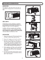 4
4
-
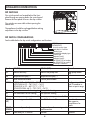 5
5
-
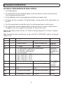 6
6
-
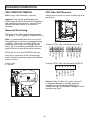 7
7
-
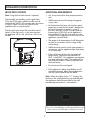 8
8
-
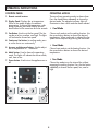 9
9
-
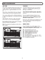 10
10
-
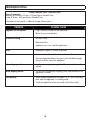 11
11
-
 12
12
-
 13
13
-
 14
14
-
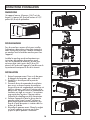 15
15
-
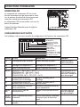 16
16
-
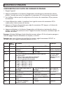 17
17
-
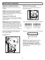 18
18
-
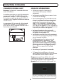 19
19
-
 20
20
-
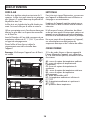 21
21
-
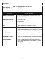 22
22
-
 23
23
-
 24
24
-
 25
25
-
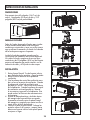 26
26
-
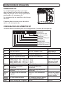 27
27
-
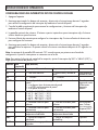 28
28
-
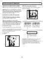 29
29
-
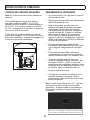 30
30
-
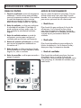 31
31
-
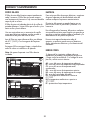 32
32
-
 33
33
-
 34
34
-
 35
35
-
 36
36


Danby DPTA090HEB1WDB El manual del propietario
- Tipo
- El manual del propietario
- Este manual también es adecuado para
en otros idiomas
Artículos relacionados
-
Danby DPSL120B1W El manual del propietario
-
Danby DAS120EAQHWDB El manual del propietario
-
-
Unbranded DPA080E3WDB6 El manual del propietario
-
-
Danby DTAC100B1WDB El manual del propietario
-
Danby DAC050MB1WDB El manual del propietario
-
Danby DPA100HE5BDB6 El manual del propietario
-
Danby DAC050ME1WDB El manual del propietario
-