Muskoka MEF2803CCHB Assembly Instructions Manual
- Categoría
- Chimeneas
- Tipo
- Assembly Instructions Manual

MEF2803CCHB
Assembly Instructions
Instructions d’assemblage
Instrucciones de montaje
REV07-20
11
YEAR
AN
AÑO
I
N
H
O
M
E
W
A
R
R
A
N
T
Y
G
A
R
A
N
T
I
E
À
L
A
M
A
I
S
O
N
G
A
R
A
N
T
Í
A
E
N
S
U
P
R
O
P
I
A
C
A
S
A
SAVE THESE INSTRUCTIONS
CONSERVER CES INSTRUCTIONS
GUARDE ESTAS INSTRUCCIONES
Electric FireplaceElectric Fireplace
Electric fireplace mantel with
corner option and 28” electric firebox
Foyer Électrique
Manteau pour foyer électrique avec option
de coin et un foyer électrique de 28”
Chimenea Eléctrica
Mueble de chimenea con opción de esquina
y caja de fuego eléctrica de 28”

TIPS FOR THE ASSEMBLY OF YOUR NEW MANTEL
Before you begin assembly, locate the instructions and hardware. Take out all the parts and compare
them to the diagrams below. Be sure you have all the parts and can identify them.
A helping hand is always good. Assemble your mantel with an adult assistant if possible. Some pieces
are heavy and will need to be held by a helper. Assembly time will take approximately 30-60 minutes.
1
ANTI-TIP DEVICE 2 SETSWINGNUT AND LOCK WASHER
INCLUDES 1 SPARE
4PCS 2PCS 2PCS 2PCS 2PCS25PCS 25PCS
TOP 1PC
ZZ.2803CCHB.08
CORNER ATTACHMENT 1PC
ZZ.2803CCHB.08-1
BASE 1PC
ZZ.2803CCHB.01
LEFT SIDE PANEL 1PC
ZZ.2803CCHB.03
CENTRAL HEADER 1PC
ZZ.2803CCHB.06
LEFT FRONT PANEL 1PC
ZZ.2803CCHB.05
RIGHT SIDE PANEL 1PC
ZZ.2803CCHB.02
UPPER FACING 1PC
ZZ.2803CCHB.07
CORNER BOTTOM
SUPPORT 1PC
ZZ.2803CCHB.09
CORNER UPRIGHT
SUPPORT 1PC
ZZ.2803CCHB.10
RIGHT FRONT PANEL 1PC
ZZ.2803CCHB.04
TOUCH UP
PAINT

GET READY TO START
Before assembly, use scissors to unwrap the parts from the packaging.
DO NOT use a box cutter or exacto-knife as you may cut into the
mantel pieces inside the box and damage the fi nish. Check for the
hardware bag which is red and located inside the packaging, taped
to the top box. Be sure you DO NOT discard any pieces.
Step 1
Locate the base and place it on the fl oor. Do not put it up against the
wall at this point in the assembly, as you need to get in behind the
mantel to insert several wingnuts, lock washers and fi rebox screws.
Step 2
Locate the left side panel and the left front panel. Facing the front
of the base, take the left side panel, positioning it so the holes in
the blocks on the bottom line up with the holes on the base. Position
the left front panel next to the left side panel, lining up the holes in
the blocks with the holes on the base. Attach the left front and side
panels to the base by inserting and tightening 1 wingnut and 1 lock
washer into each of the 2 blocks. Attach the left side and front panels
together by inserting and tightening 3 wingnuts and 3 lock washers
through the holes in the 3 blocks.
Step 3
Repeat Step 2, but with the right side panel and the right front panel.
Step 4
Locate the brick upper facing panel that will be attached to the left
and right legs and will sit above the fi rebox. Position this panel with
the brick side facing the front of the mantel. Line up the holes on each
side and insert and tighten 1 wingnut and 1 lock washer on each
side.
Step 5
Locate the central header that will be attached to the left and right
legs and will sit above the upper facing panel. Position this panel
with the fi nished side facing the front of the mantel. Line up the holes
on each side and insert and tighten 2 wingnuts and 2 lock washers
on each side. Attach the upper facing panel to the central header by
lining up the holes in the center of each part into the hole. Insert and
tighten 1 wingnut and 1 lockwasher.
2
Step 4 & 5
Step 1
Step 2 & 3

Step 6
Get your assistant and locate the top of your mantel. This top is very
heavy, it will take 2 people to lift and position it in place. Ensure
the top goes over the positioning guide located on the header. The
top must go over this guide to be positioned correctly. Line up the
holes on the top of the mantel, insert and tighten 5 wingnuts and 5
lockwashers.
Step 7
If you are using this mantel in a corner application, locate the triangular
piece of wood which attaches to the mantel to create the corner unit.
You must attach this piece for all corner applications. Slide the corner
bottom support into the channel located at the middle of the back of
the hearth base. Place the top corner attachment on the floor upside
down. Protect it from damage. Attach the corner upright support to the
corner attachment by lining up the hole in the corner upright with hole
in the corner top then insert 1 wingnut and 1 lock washer through the
holes in the block and tighten. Simply take the triangle and slide the
brackets with the holes onto the pins which are already attached to
the mantel. Once the triangle is attached, push it up so it is level with
the mantel and lock it into place. To lock it into place simply turn the
3 horizontal wooden blocks attached to the underside of the mantel
into a vertical position to support the weight of the corner triangle.
Insert and tighten 1 wingnut and 1 lock washer into each block. Now
attach the corner bottom support to the corner upright support by
insert and tightening 1 wingnut and 1 lock washer through the holes
at the end of each piece.
Step 6
Step 7
3

Step 8
Step 8
Take your electric firebox out of its packaging and position it between
the 2 legs of the mantel. Once you are close to the wall, plug the
firebox into the nearest outlet.
The firebox comes with 3 metal brackets and 16 black screws (15
required plus 1 spare). These metal brackets must be attached to all
3 sides of the firebox and 2 sides of the mantel to ensure that your
firebox does not move around as you use it. All 3 trims attach to
the firebox by inserting and tightening 3 screws. Both the left and
right side trim attach to the mantel front by inserting and tightening
3 screws
The top trim does not attach to the mantel, just the firebox. if you
have any questions about the firebox please reference the installation
instructions that come with the firebox.
4

Anti-tipping device (instructions included with hardware)
1. Attach one of the mounting brackets securely to the back edge of
the furniture. Use the shorter screw.
2. Determine where furniture is to be placed and mark location
on the wall for the mounting bracket screw hole approximately 2”
(51mm) below the bracket mounted to the edge of the furniture.
3. Drill a 3/16” (5 mm) hole in the wall. Press the plastic anchor into
the hole and gently tap until the flange on the anchor is against the
wall surface.
4. Position the bracket over the anchor and use the longer screw to
securely attach the bracket to wall.
5. Place the furniture so the bracket on the back edge is in line with
the bracket on the wall.
6. Place an end of the nylon restraint strap down through each
bracket. Bring both ends together and slide the beaded end of
the strap through the keyhole-shaped slot in the other end until
snug. Pull down on the beaded end until it snap locks into the
keyhole slot.
7. To double lock, return the beaded end back through the keyhole
as shown.
8. Check to make sure the strap is securely laced and locked to
the brackets.
For a corner application, use 2 furniture tipping restraints as shown
in FIG. 2
Young children may be injured by tipping furniture. The use of a
tipping restraint is highly recommended. This hardware, when
properly installed, could provide protection against the unexpected
tipping of furniture due to improper use.
WARNING: THIS PRODUCT IS ONLY A DETERRENT. IT IS
NOT A SUBSTITUTE FOR PROPER ADULT SUPERVISION.
One anti-tip device includes the following:
Two anti-tip devices have been included for corner applications.
5
Nylon restraint strap
Bracket
Plastic
anchor
Fig. 1
Fig. 2
1225
1165
694
594
925
376
1054
2009-MEF2822CWG-1
1
2
3
4
5
6
1
1
1
1
1
1
RIGHT SIDE PANEL
MODEL
ITEM NAME
PART NO.
MANTEL
PART NAME
QTY.
BASE
7
1
8
8-1
1
1
CORNER AT TA CHMENT
TOP
9
1
CORNER BOTTOM SUPPORT
10
1
CORNER UPRIGHT SUPPORT
2009-MEF2822CWG-1
6
8
8 -1
1
2
4
5
3
7
10
9
11
1
11
FIREBOX SHELF
BASE 1PC
TOP 1PC
FLAT HEAD SCREW(4*30mm)4PCS
FLAT HEAD SCREW(4*16mm)4PCS
2PCS
2PCS
4PCS
WING NUT(5*28) 25PCS
STEP 1
STEP 2
STEP 3
STEP 4
STEP 5
STEP 6 STEP 7
STEP 8
STEP 9
LEFT SIDE PANEL
RIGHT FRONT PANEL
LEFT FRONT PANEL
UPPER FACING
LOWER FACING
RIGHT SIDE PANEL 1PC
LEFT SIDE PANEL 1PC
RIGHT FRONT PANEL 1PC
LEFT FRONT PANEL 1PC
UPPER FACING 1PC
LOWER FACING 1PC
STEP 10
CORNER ATTACHMENT 1PC
CORNER BOTTOM SUPPORT 1PC
CORNER UPRIGHT SUPPORT 1PC
FIREBOX SHELF 1PC
LOCK WASHER 25PCS
1225
1165
694
594
925
376
1054
2009-MEF2822CWG-1
1
2
3
4
5
6
1
1
1
1
1
1
RIGHT SIDE PANEL
MODEL
ITEM NAME
PART NO.
MANTEL
PART NAME
QTY.
BASE
7
1
8
8-1
1
1
CORNER AT TACHMENT
TOP
9
1
CORNER BOTTOM SUPPORT
10
1
CORNER UPRIGHT SUPPORT
2009-MEF2822CWG-1
6
8
8 -1
1
2
4
5
3
7
10
9
11
1
11
FIREBOX SHELF
BASE 1PC
TOP 1PC
FLAT HEAD SCREW(4*30mm)4PCS
FLAT HEAD SCREW(4*16mm)4PCS
2PCS
2PCS
4PCS
WING NUT(5*28) 25PCS
STEP 1
STEP 2
STEP 3
STEP 4
STEP 5
STEP 6 STEP 7
STEP 8
STEP 9
LEFT SIDE PANEL
RIGHT FRONT PANEL
LEFT FRONT PANEL
UPPER FACING
LOWER FACING
RIGHT SIDE PANEL 1PC
LEFT SIDE PANEL 1PC
RIGHT FRONT PANEL 1PC
LEFT FRONT PANEL 1PC
UPPER FACING 1PC
LOWER FACING 1PC
STEP 10
CORNER ATTACHMENT 1PC
CORNER BOTTOM SUPPORT 1PC
CORNER UPRIGHT SUPPORT 1PC
FIREBOX SHELF 1PC
LOCK WASHER 25PCS
1225
1165
694
594
925
376
1054
2009-MEF2822CWG-1
1
2
3
4
5
6
1
1
1
1
1
1
RIGHT SIDE PANEL
MODEL
ITEM NAME
PART NO.
MANTEL
PART NAME
QTY.
BASE
7
1
8
8-1
1
1
CORNER AT TA CHMENT
TOP
9
1
CORNER BOTTOM SUPPORT
10
1
CORNER UPRIGHT SUPPORT
2009-MEF2822CWG-1
6
8
8 -1
1
2
4
5
3
7
10
9
11
1
11
FIREBOX SHELF
BASE 1PC
TOP 1PC
FLAT HEAD SCREW(4*30mm)4PCS
FLAT HEAD SCREW(4*16mm)4PCS
2PCS
2PCS
4PCS
WING NUT(5*28) 25PCS
STEP 1
STEP 2
STEP 3
STEP 4
STEP 5
STEP 6 STEP 7
STEP 8
STEP 9
LEFT SIDE PANEL
RIGHT FRONT PANEL
LEFT FRONT PANEL
UPPER FACING
LOWER FACING
RIGHT SIDE PANEL 1PC
LEFT SIDE PANEL 1PC
RIGHT FRONT PANEL 1PC
LEFT FRONT PANEL 1PC
UPPER FACING 1PC
LOWER FACING 1PC
STEP 10
CORNER ATTACHMENT 1PC
CORNER BOTTOM SUPPORT 1PC
CORNER UPRIGHT SUPPORT 1PC
FIREBOX SHELF 1PC
LOCK WASHER 25PCS
1225
1165
694
594
925
376
1054
2009-MEF2822CWG-1
1
2
3
4
5
6
1
1
1
1
1
1
RIGHT SIDE PANEL
MODEL
ITEM NAME
PART NO.
MANTEL
PART NAME
QTY.
BASE
7
1
8
8-1
1
1
CORNER AT TA CHMENT
TOP
9
1
CORNER BOTTOM SUPPORT
10
1
CORNER UPRIGHT SUPPORT
2009-MEF2822CWG-1
6
8
8 -1
1
2
4
5
3
7
10
9
11
1
11
FIREBOX SHELF
BASE 1PC
TOP 1PC
FLAT HEAD SCREW(4*30mm)4PCS
FLAT HEAD SCREW(4*16mm)4PCS
2PCS
2PCS
4PCS
WING NUT(5*28) 25PCS
STEP 1
STEP 2
STEP 3
STEP 4
STEP 5
STEP 6 STEP 7
STEP 8
STEP 9
LEFT SIDE PANEL
RIGHT FRONT PANEL
LEFT FRONT PANEL
UPPER FACING
LOWER FACING
RIGHT SIDE PANEL 1PC
LEFT SIDE PANEL 1PC
RIGHT FRONT PANEL 1PC
LEFT FRONT PANEL 1PC
UPPER FACING 1PC
LOWER FACING 1PC
STEP 10
CORNER ATTACHMENT 1PC
CORNER BOTTOM SUPPORT 1PC
CORNER UPRIGHT SUPPORT 1PC
FIREBOX SHELF 1PC
LOCK WASHER 25PCS
2PCS 1PCS 1PCS 1PCS 1PCS

6
WARRANTY
Greenway Home Products is pleased to offer in-home warranty repairs. Please refer to your Firebox Use and Care Guide for warranty
information on your Firebox.
DO NOT RETURN THIS PRODUCT TO THE STORE:
Please contact Customer Service at: 1-866-253-0447
Monday to Thursday from 8:30AM to 5:00PM (EST), Friday from 8:30AM to 4:00PM (EST)
Web: www.greenwayhp.com
Email: [email protected]
Canada:
400 Southgate Dr., Guelph, Ontario, Canada, N1G 4P5
USA: 1270 Flagship Dr., Perrysburg, Ohio, USA, 43551
Limited Warranty Definitions:
Greenway Home Products:
(Greenway) Manufacturer.
Mantel: Mantel manufactured by Greenway Home Products.
Purchaser: Purchaser of the Mantel
Distributor: Facility authorized to sell Greenway Home Products.
Warranty Card Greenway Home Products Limited Warranty Registration Card identifying the Purchaser and product model.
Greenway Limited Warranty:
Greenway warrants to the Purchaser that the Mantel is free from defects in material and workmanship, under normal use and service, for
1 year (1 year limited parts) from the date of purchase.
All warranty repairs must be preauthorized by Greenway Home Products. Greenway will, at its’ option, replace or repair free of charge
any defective part, which the Purchaser shall notify their Distributor or Greenway Home Products within the warranty period. The obligation
of Greenway Home Products under this warranty, is expressly limited to such replacement or repairs.
The provisions of this limited warranty shall not apply to the following:
1. Accidents.
2. Unauthorized repairs or alterations.
3. Normal maintenance.
4. Changes made to other units manufactured after this mantel was manufactured.
5. Incidental damages caused by failure of the mantel such as inconvenience or loss of use.
6. Improper installation.
The provisions of this limited warranty shall not apply to deterioration due to wear and exposure beyond the following limitations:
1. For 180 days from the date of purchase for exterior finished surfaces.
Due to the properties of natural wood, Greenway Home Products makes no warranty against mineraling of wood components.
Greenway Limited Warranty is void unless the following conditions are adhered to:
1. Warranty registration must be completed and returned to a Greenway Home Products.
2. All warranty repairs must be preauthorized by a Greenway repair facility.
3. Greenway reserves the right to inspect defective parts that have been replaced under warranty. Dealer is expected to hold
defective parts for 60 days.
4. Only parts and accessories and other material, available through Greenway Home Products are to be used in the performance
of warranty service.
5. Purchasers are responsible for presenting/notifying their Distributor as soon a problem exists. The warranty repairs should be
completed in a reasonable amount of time from the date of authorization. Not to exceed 30 days past notification.
This limited warranty is expressly in lieu of any other expressed or implied warranty, including any implied warranty or merchantability
or fitness for a particular purpose and of any obligations or liabilities on Greenway Home Products which neither assumes nor
authorizes any other person to assume for it any other liability in connection with the Mantel
manufactured by it.
The warranty is null and void if used in commercial or industrial applications.

MEF2803CCHB
Assembly Instructions
Instructions d’assemblage
Instrucciones de montaje
REV07-20
11
YEAR
AN
AÑO
I
N
H
O
M
E
W
A
R
R
A
N
T
Y
G
A
R
A
N
T
I
E
À
L
A
M
A
I
S
O
N
G
A
R
A
N
T
Í
A
E
N
S
U
P
R
O
P
I
A
C
A
S
A
SAVE THESE INSTRUCTIONS
CONSERVER CES INSTRUCTIONS
GUARDE ESTAS INSTRUCCIONES
Electric FireplaceElectric Fireplace
Electric fireplace mantel with
corner option and 28” electric firebox
Foyer Électrique
Manteau pour foyer électrique avec option
de coin et un foyer électrique de 28”
Chimenea Eléctrica
Mueble de chimenea con opción de esquina
y caja de fuego eléctrica de 28”

CONSEJOS PARA EL ENSAMBLADO DE SU NUEVA REPISA DE CHIMENEA
Antes de comenzar el ensamblado, localice las instrucciones y los accesorios. Saque todos los componentes
y compárelos con los diagramas que aparecen a continuación. Asegúrese de tener todos los componentes
y que puede identifi carlos.
Siempre es bueno tener alguien que le ayude; de ser posible consiga que un adulto le ayude a ensamblar
su repisa de chimenea. Algunas piezas son pesadas y necesitará que se las sostenga un ayudante. El
tiempo de ensamblado tomerá de 30 a 60 minutos aproximadamente.
1
DISPOSITIVO ANTI-VOLCADURAS 2 JUEGOSTUERCA DE MARIPOSA Y
ARANDELA DE PRESIÓN
INCLUYE UNA PIEZA DE REPUESTO
4PZA 2PZA 2PZA 2PZA 2PZA
25PZA 25PZA
PARTE SUPERIOR
1 PZA
ZZ.2803CCHB.08
PIEZA DE ESQUINA
1 PZA
ZZ.2803CCHB.08-1
BASE 1 PZA
ZZ.2803CCHB.01
PANEL LATERAL
IZQUIERDO 1 PZA
ZZ.2803CCHB.03
PANEL DELANTERO
1 PZA
ZZ.2803CCHB.06
PANEL FRONTAL
IZQUIERDO 1 PZA
ZZ.2803CCHB.05
PANEL LATERAL DERECHO
1 PZA
ZZ.2803CCHB.02
PANEL LADO SUPERIOR
1 PZA
ZZ.2803CCHB.07
SOPORTE DE LA ESQUINA
INFERIOR 1 PZA
ZZ.2803CCHB.09
SOPORTE DE LA
ESQUINA DERECHA
SUPERIOR 1 PZA
ZZ.2803CCHB.10
PANEL FRONTAL DERECHO
1 PZA
ZZ.2803CCHB.04
PINTURE DE
RETOQUE

2
PREPÁRESE A EMPEZAR
Antes del ensamblado, use tijeras para desenvolver los componentes
del embalaje. NUNCA use una navaja multiuso o un cuchillo, ya que
podría dañar las piezas de la repisa de chimenea dentro de la caja
y dañar el acabado. Busque la bolsa de accesorios, que es de color
rojo y que se encuentra dentro del embalaje, adherida a la caja
superior. Asegúrese de no perder ningún compnente.
Paso 1
Localice la base y coloquela en el piso. No lo coloque contra la
pared en este momento del ensamblado, ya que usted necesita
tener acceso a la parte de atrás de la repisa de chimenea para
insertar varios tornillos.
Paso 2
Localice el panel lateral izquierdo y el panel frontal izquierdo.
Parándose de frente a la base, tome el panel lateral izquierdo,
colocándolo de manera tal que los agujeros en los bloques en la
linea de abajo estén alineados con los agujeros en la base. Coloque
el panel frontal izquierdo junto al panel lateral izquierdo, alineando
los agujeros en los bloques con los agujeros en la base. Fije la
parte frontal izquierda y los paneles laterales a la base insertando y
ajustando 1 tuerca de mariposa y 1 arandela de seguridad en cada
uno de los 2 bloques. Fije el lado izquierdo y paneles delanteros
unidos insertando y ajustando 3 tuercas de mariposa y 3 arandelas
de seguridad a través de los agujeros en los 3 bloques.
Paso 3
Repita el Paso 2, pero con el panel lateral derecho y el panel frontal
derecho.
Paso 4
Ubique la parte superior frontal de ladrillo que se adjuntará a los
pilares derecho e izquierdo y reposa encima de la caja de fuego.
Coloque este panel con la parte de ladrillo hacia la parte frontal
de la repisa de la chimenea. Alinee los orifi cios en cada lado
e inserte y ajuste 1 tuerca de mariposa y 1 arandela de seguridad
en cada lado.
Paso 5
Ubique el panel central principal, que se adjuntará a los pilares derecho
e izquierdo y reposa encima del panel superior delantero. Coloque este
panel con la parte acabada hacia la parte frontal de la repisa de la
chimenea. Alinee los orifi cios en cada lado e inserte y ajuste 2 tuercas
de mariposa y 2 arandelas de bloqueo en cada lado. Fije el panel
superior delantero al panel central principal, alineando los agujeros
en el centro de cada parte en el agujero. Inserte y ajuste 1 tuerca de
mariposa y 1 arandela de seguridad.
Paso 2 & 3
Paso 4 & 5
Paso 1

3
Paso 6
Con su ayudante localice la parte superior de su repisa de chimenea.
Esta pieza es muy pesada. Se necesitarán 2 personas para levantarla
y colocarla en su sitio. Asegúrese de que la parte superior vaya
por encima de la guía de ubicación localizada en la cabecera. La
parte superior debe colocarse sobre la guía para ser ensamblada
correctamente. Alinear los orificios de la parte superior, inserte y
ajuste con 5 tuercas de mariposa y 5 arandelas de presión.
Paso 7
Si quiere usar la repisa en una esquina, localice la pieza triangular
de madera que se afianza al mueble a la repisa para formar la
esquinera. Deslice el soporte inferior en la ranura ubicada en
el medio de la parte posterior de la base del mueble. Coloque
el accesorio de esquina superior en el piso de manera invertida.
Evite que se dañe. Fije el soporte vertical al accesorio angular de
esquina. Para hacerlo, alinee el orificio del soporte vertical con el
orificio de la pieza de esquina, utilice 1 tuerca y 1 arandela de
presión. Esta pieza debe afianzarse para todos los usos en esquinas.
Simplemente tome el triángulo y deslice los soportes con los orificios
en las espigas que ya vienen afianzadas a la repisa. Después de
ajustar el triángulo, ponerlo a nivel con la repisa de chimenea y
ajústelos juntos. Para ajustarlo, girar las 3 piezas horizontales de
madera en la parte inferior de la repisa en su posición vertical para
soportar el peso de la pieza de esquina. Para fortalecer su pieza de
esquina coloque el soporte verticalmente debajo de la “punta” de la
pieza de esquina. Inserte y ajuste usando 1 tuerca de mariposa y 1
arandela de presión en cada pieza. A continuación, una el soporte
inferior angular al soporte vertical, y ajuste 1 tuerca de mariposa y
1 arandela de presión.
Paso 6
Paso 7

4
Paso 8
Retire su caja eléctrica del embalaje y colóquela sobre la base entre
los 2 pilares del mueble. Una vez que esté cerca de la pared conecte
la caja de fuego al toma de corriente más cercano.
La caja de fuego eléctrica incluye 3 soportes de metal y 16 tornillos
negros (15 tornillos requeridos más 1 adicional). Estos soportes de
metal deben ser fijados a los 3 lados de la caja de fuego y a los 2
lados del mueble para asegurar que la caja de fuego no se mueva al
usarla. Los 3 soportes se fijan a la caja de fuego usando 3 tornillos.
Tanto el soporte izquierdo como el soporte derecho se fijan a la parte
delantera del mueble mediante el ajuste de 3 tornillos.
El soporte superior no se fija al mueble, solo a la caja de fuego
eléctrica. Si tiene alguna pregunta sobre la caja de fuego, por favor
refiérase a las instrucciones de instalación que vienen con la misma.
Paso 8

Dispositivo Anti-Vuelco (instrucciones con la ferretería incluida)
1. Adjunte una de las montaduras firmemente al dorso y en la parte
de arriba del mueble. Use el tornillo mas corto.
2. Determine donde va a poner el mueble y marque el lugar en la
pared donde va el agujero del tornillo de la montadura
aproximadamente 2” del soporte.
3. Taladre un agujero de 3/16” en la pared. Presione el ancla
plástica en el agujero dando golpecitos hasta que esté dentro de
la pared.
4. Ponga el soporte sobre el ancla plástica y use el tornillo más
largo para sujetarlo de forma segura a la pared.
5. Ponga el mueble de forma tal que la montadura este en linea con la
montadura de la pared.
6. Enlace la correa de nylon por la montadura. Ponga las dos puntas
juntas y delice la punta de las cuentas or la ranura de la orta
punta, tire hasta que esté bien ajustada.
7. Para que ponga la punta de las bolitas por la ranura otra vez
como se demuestra.
8. Verifique si la correa está seguramente enlazada a la montadura.
Para una aplicación de esquina, use los 2 soportes de restricción
antivuelco, como se muestra en la FIG. 2
Los niños pueden accidentarse volcándose muebles encima. El uso
de soportes anit-vuelco es altamente recomendado. Estos materiales
de prevención, cuando están apropiadamente instalados, pueden
prevenir la inclinación y caída del mueble, causados por el uso
inapropiado.
ADVERTENCIA: ESTE PRODUCTO ES SOLAMENTE DE
PREVENCIÓN Y NO REEMPLAZA LA SUPERVISIÓN
DE UN ADULTO.
1 dispositivo anit-vuelco incluye lo siguiente:
2 dispositivos anti-vuelco han sido incluidos para la aplicación
esquina.
Correa de nylon
Montadura
Ancla
plastique
Fig. 1
Fig. 2
1225
1165
694
594
925
376
1054
2009-MEF2822CWG-1
1
2
3
4
5
6
1
1
1
1
1
1
RIGHT SIDE PANEL
MODEL
ITEM NAME
PART NO.
MANTEL
PART NAME
QTY.
BASE
7
1
8
8-1
1
1
CORNER AT TA CHMENT
TOP
9
1
CORNER BOTTOM SUPPORT
10
1
CORNER UPRIGHT SUPPORT
2009-MEF2822CWG-1
6
8
8 -1
1
2
4
5
3
7
10
9
11
1
11
FIREBOX SHELF
BASE 1PC
TOP 1PC
FLAT HEAD SCREW(4*30mm)4PCS
FLAT HEAD SCREW(4*16mm)4PCS
2PCS
2PCS
4PCS
WING NUT(5*28) 25PCS
STEP 1
STEP 2
STEP 3
STEP 4
STEP 5
STEP 6 STEP 7
STEP 8
STEP 9
LEFT SIDE PANEL
RIGHT FRONT PANEL
LEFT FRONT PANEL
UPPER FACING
LOWER FACING
RIGHT SIDE PANEL 1PC
LEFT SIDE PANEL 1PC
RIGHT FRONT PANEL 1PC
LEFT FRONT PANEL 1PC
UPPER FACING 1PC
LOWER FACING 1PC
STEP 10
CORNER ATTACHMENT 1PC
CORNER BOTTOM SUPPORT 1PC
CORNER UPRIGHT SUPPORT 1PC
FIREBOX SHELF 1PC
LOCK WASHER 25PCS
1225
1165
694
594
925
376
1054
2009-MEF2822CWG-1
1
2
3
4
5
6
1
1
1
1
1
1
RIGHT SIDE PANEL
MODEL
ITEM NAME
PART NO.
MANTEL
PART NAME
QTY.
BASE
7
1
8
8-1
1
1
CORNER AT TACHMENT
TOP
9
1
CORNER BOTTOM SUPPORT
10
1
CORNER UPRIGHT SUPPORT
2009-MEF2822CWG-1
6
8
8 -1
1
2
4
5
3
7
10
9
11
1
11
FIREBOX SHELF
BASE 1PC
TOP 1PC
FLAT HEAD SCREW(4*30mm)4PCS
FLAT HEAD SCREW(4*16mm)4PCS
2PCS
2PCS
4PCS
WING NUT(5*28) 25PCS
STEP 1
STEP 2
STEP 3
STEP 4
STEP 5
STEP 6 STEP 7
STEP 8
STEP 9
LEFT SIDE PANEL
RIGHT FRONT PANEL
LEFT FRONT PANEL
UPPER FACING
LOWER FACING
RIGHT SIDE PANEL 1PC
LEFT SIDE PANEL 1PC
RIGHT FRONT PANEL 1PC
LEFT FRONT PANEL 1PC
UPPER FACING 1PC
LOWER FACING 1PC
STEP 10
CORNER ATTACHMENT 1PC
CORNER BOTTOM SUPPORT 1PC
CORNER UPRIGHT SUPPORT 1PC
FIREBOX SHELF 1PC
LOCK WASHER 25PCS
1225
1165
694
594
925
376
1054
2009-MEF2822CWG-1
1
2
3
4
5
6
1
1
1
1
1
1
RIGHT SIDE PANEL
MODEL
ITEM NAME
PART NO.
MANTEL
PART NAME
QTY.
BASE
7
1
8
8-1
1
1
CORNER AT TA CHMENT
TOP
9
1
CORNER BOTTOM SUPPORT
10
1
CORNER UPRIGHT SUPPORT
2009-MEF2822CWG-1
6
8
8 -1
1
2
4
5
3
7
10
9
11
1
11
FIREBOX SHELF
BASE 1PC
TOP 1PC
FLAT HEAD SCREW(4*30mm)4PCS
FLAT HEAD SCREW(4*16mm)4PCS
2PCS
2PCS
4PCS
WING NUT(5*28) 25PCS
STEP 1
STEP 2
STEP 3
STEP 4
STEP 5
STEP 6 STEP 7
STEP 8
STEP 9
LEFT SIDE PANEL
RIGHT FRONT PANEL
LEFT FRONT PANEL
UPPER FACING
LOWER FACING
RIGHT SIDE PANEL 1PC
LEFT SIDE PANEL 1PC
RIGHT FRONT PANEL 1PC
LEFT FRONT PANEL 1PC
UPPER FACING 1PC
LOWER FACING 1PC
STEP 10
CORNER ATTACHMENT 1PC
CORNER BOTTOM SUPPORT 1PC
CORNER UPRIGHT SUPPORT 1PC
FIREBOX SHELF 1PC
LOCK WASHER 25PCS
1225
1165
694
594
925
376
1054
2009-MEF2822CWG-1
1
2
3
4
5
6
1
1
1
1
1
1
RIGHT SIDE PANEL
MODEL
ITEM NAME
PART NO.
MANTEL
PART NAME
QTY.
BASE
7
1
8
8-1
1
1
CORNER AT TA CHMENT
TOP
9
1
CORNER BOTTOM SUPPORT
10
1
CORNER UPRIGHT SUPPORT
2009-MEF2822CWG-1
6
8
8 -1
1
2
4
5
3
7
10
9
11
1
11
FIREBOX SHELF
BASE 1PC
TOP 1PC
FLAT HEAD SCREW(4*30mm)4PCS
FLAT HEAD SCREW(4*16mm)4PCS
2PCS
2PCS
4PCS
WING NUT(5*28) 25PCS
STEP 1
STEP 2
STEP 3
STEP 4
STEP 5
STEP 6 STEP 7
STEP 8
STEP 9
LEFT SIDE PANEL
RIGHT FRONT PANEL
LEFT FRONT PANEL
UPPER FACING
LOWER FACING
RIGHT SIDE PANEL 1PC
LEFT SIDE PANEL 1PC
RIGHT FRONT PANEL 1PC
LEFT FRONT PANEL 1PC
UPPER FACING 1PC
LOWER FACING 1PC
STEP 10
CORNER ATTACHMENT 1PC
CORNER BOTTOM SUPPORT 1PC
CORNER UPRIGHT SUPPORT 1PC
FIREBOX SHELF 1PC
LOCK WASHER 25PCS
1225
1165
694
594
925
376
1054
2009-MEF2822CWG-1
1
2
3
4
5
6
1
1
1
1
1
1
RIGHT SIDE PANEL
MODEL
ITEM NAME
PART NO.
MANTEL
PART NAME
QTY.
BASE
7
1
8
8-1
1
1
CORNER AT TA CHMENT
TOP
9
1
CORNER BOTTOM SUPPORT
10
1
CORNER UPRIGHT SUPPORT
2009-MEF2822CWG-1
6
8
8 -1
1
2
4
5
3
7
10
9
11
1
11
FIREBOX SHELF
BASE 1PC
TOP 1PC
FLAT HEAD SCREW(4*30mm)4PCS
FLAT HEAD SCREW(4*16mm)4PCS
2PCS
2PCS
4PCS
WING NUT(5*28) 25PCS
STEP 1
STEP 2
STEP 3
STEP 4
STEP 5
STEP 6 STEP 7
STEP 8
STEP 9
LEFT SIDE PANEL
RIGHT FRONT PANEL
LEFT FRONT PANEL
UPPER FACING
LOWER FACING
RIGHT SIDE PANEL 1PC
LEFT SIDE PANEL 1PC
RIGHT FRONT PANEL 1PC
LEFT FRONT PANEL 1PC
UPPER FACING 1PC
LOWER FACING 1PC
STEP 10
CORNER ATTACHMENT 1PC
CORNER BOTTOM SUPPORT 1PC
CORNER UPRIGHT SUPPORT 1PC
FIREBOX SHELF 1PC
LOCK WASHER 25PCS
2PZA 1PZA 1PZA 1PZA 1PZA
5

6
GARANTÍA
Greenway Home Products se complace en ofrecerle servicio de reparación a domicilio dentro de la garantía. Consulte el Manual del uso
y mantenimiento para información adicional sobre la garantía.
NO DEVUELVA ESTE PRODUCTO A LA TIENDA:
Comuníquese a Servicio al Cliente llamando a la linea telefónica gratuita: 1-866-253-0447
Lunes a Jueves de 8:30 AM a 5:00 PM (hora del Este), Viernes de 8:30 AM a 4:00 PM (hora del Este)
Sitio web: www.greenwayhp.com
Correo electrónico: [email protected]
Canadá: 400 Southgate Dr., Guelph, Ontario, Canada, N1G 4P5
EE.UU: 1270 Flagship Dr., Perrysburg, Ohio, USA, 43551
Definiciones de la garantía limitada:
Greenway Home Products: Fabricante.
Repisa de chimenea: Repisa de chimenea fabricada por Greenway Home Products.
Comprador: El Comprador de la repisa de chimenea:
Distribuidor: La organización autorizada para la venta de productos domésticos Greenway Home Products.
Tarjeta de garantía La tarjeta de registro de garantía limitada de Greenway Home Products que identifica al
comprador y al número de modelo.
Garantía limitada de Greenway:
Greenway garantiza al Comprador que la Repisa de chimenea está libre de defectos de materiales y mano de obra por 1 año, bajo uso
normal y servicio (1 año para componentes limitados) a partir de la fecha de la compra.
Greenway Home Products deberá autorizar previamente todas las reparaciones bajo garantía. A su opción, Greenway, reemplazará
o reparará sin costo, cualquier componente defectuoso, después de que el comprador informe a su Distribuidor o a Greenway Home
Products, dentro del periodo de garantía. Bajo esta garantía, la obligación de Greenway Home Products está limitada expresamente al
tal reemplazo o reparación.
Los términos de esta garantía limitada no se aplican a los siguientes:
1. Accidentes
2. Reparaciones o modificaciones no autorizadas
3. Mantenimiento normal
4. Modificaciones que se ejecutaron en otras unidades fabricadas después de fabricar este Repisa de chimenea.
5. Daños incidentales causados por fallas del Repisa de chimenea tal como molestias o pérdida del uso
6. Instalación incorrecta
Los términos de esta garantía no se aplican al deterioro debido al desgaste y exposición más allá de las limitaciones
siguientes:
1. Las superficies externas acabadas por 180 días posteriores a la fecha de compra.
Debido a las propiedades de la madera natural, Greenway Home Products no ofrece ninguna garantía contra salinización de los
componentes de madera.
La garantía limitada de Greenway no tiene validez salvo que se acepten las condiciones siguientes:
1. El registro de garantía debe ser llenado y mandado a Greenway Home Products.
2. La instalación de reparaciones de Greenway deberá autorizar previamente todas las reparaciones bajo garantía.
3. Greenway se reserva el derecho de inspeccionar los componentes defectuosos que se hubieran reemplazado bajo la garantía. El
distribuidor deberá conservar los componentes defectuosos durante 60 días.
4. Para cumplir debidamente con la garantía, se deberán utilizarse solamente componentes, accesorios y otros materiales disponibles
a través de Greenway Home Products.
5. Es responsabilidad de los compradores el presentarse o informar al distribuidor tan pronto como se suscite un problema. Las
reparaciones bajo la garantía deberán llevarse a cabo en un plazo razonable después de la fecha de la autorización. No deberá
sobrepasar más de 30 días después de la notificación.
Esta garantía sustituye expresamente cualquier otra garantía expresada o implícita, incluida cualquier garantía implícita o de comercialización
o apropiada para algún propósito en particular y de cualquier otras obligaciones o limitaciones de Greenway Home Products, el cual no
acepta ni autoriza a ninguna otra persona de aceptar por ella ninguna otra responsabilidad en lo
que se refiere de Repisa de chimenea fabricado por la misma.
Esta garantía es nula y sin efecto si se utiliza en aplicaciones comerciales o industriales.

MEF2803CCHB
Assembly Instructions
Instructions d’assemblage
Instrucciones de montaje
REV07-20
11
YEAR
AN
AÑO
I
N
H
O
M
E
W
A
R
R
A
N
T
Y
G
A
R
A
N
T
I
E
À
L
A
M
A
I
S
O
N
G
A
R
A
N
T
Í
A
E
N
S
U
P
R
O
P
I
A
C
A
S
A
SAVE THESE INSTRUCTIONS
CONSERVER CES INSTRUCTIONS
GUARDE ESTAS INSTRUCCIONES
Electric FireplaceElectric Fireplace
Electric fireplace mantel with
corner option and 28” electric firebox
Foyer Électrique
Manteau pour foyer électrique avec option
de coin et un foyer électrique de 28”
Chimenea Eléctrica
Mueble de chimenea con opción de esquina
y caja de fuego eléctrica de 28”

CONSEILS POUR L’ASSEMBLAGE DE VOTRE NOUVEAU MANTEAU
Avant d’entreprendre l’assemblage, trouvez les instructions et les articles de quincaillerie. Sortez les
composants et comparez-les par rapport aux schémas ci-dessous. Assurez-vous que vous avez toutes les
pièces et que vous pouvez les identifi er.
L’aide d’une autre personne est toujours bienvenue. Assemblez votre manteau avec l’aide d’un autre
adulte si c’est possible. Certains composants sont lourds et l’autre personne pourra les tenir. Il vous faudra
environ 30-60 minutes approximativement pour faire l’assemblage.
1
2 DISPOSITIFS ANTI-BASCULEMENTÉCROU PAPILLON ET
RONDELLE FREIN
INCLUT 1 PIÈCE DE RECHANGE
4PCS 2PCS 2PCS 2PCS 2PCS25PCS 25PCS
1 DESSUS
ZZ.2803CCHB.08
1 ATTACHEMENT
FAISANT LE COIN
ZZ.2803CCHB.08-1
1 BASE
ZZ.2803CCHB.01
PANNEAU LATÉRAL
GAUCHE 1PC
ZZ.2803CCHB.03
BOUTISSE CENTRAL 1PC
ZZ.2803CCHB.06
PANNEAU DE DEVANT
GAUCHE 1PC
C
ZZ.2803CCHB.05
PANNEAU LATÉRAL
DROIT 1PC
ZZ.2803CCHB.02
PANNEAU CÔTÉ
SUPÉRIEUR 1PC
ZZ.2803CCHB.07
SUPPORT DE COIN
INFÉRIEUR 1PC
ZZ.2803CCHB.09
SUPPORT DE COIN
DROIT 1PC
ZZ.2803CCHB.10
PANNEAU DE DEVANT
DROIT 1PC
ZZ.2803CCHB.04
TOUCHE DE
PEINTURE

2
PRÉPAREZ-VOUS À COMMENCER
Avant de commencer l’assemblage, utilisez des ciseaux pour
déballer les pièces de leur emballage. N’UTILISEZ PAS un couteau
pour les boîtes ou un exacto pour ne pas couper le manteau à
l’intérieur de la boîte et pour ne pas endommager la fi nition.
Vérifi ez le sac rouge contenant les articles de quincaillerie; ce
sac se trouve à l’intérieur de l’emballage; le sac est fi xé à l’aide
de ruban adhésif sur la boîte supérieure. Assurez-vous que vous
ne jetez aucune pièce.
Étape 1
Ramasser la tablette de base et la placer sur le plancher. Ne l’adossez
pas à un mur à ce point-ci de l’assemblage parce que vous devrez
aller derrière le manteau pour y insérer plusieurs vis.
Étape 2
Trouvez le panneau latéral gauche et le panneau avant-gauche.
Mettez-vous en face de la tablette de base; placer le panneau latéral
gauche avec les trous au fond de la pièce alignés avec ceux de la
tablette de base. Mettre en place le panneau de devant gauche à
côté du panneau latéral gauche en alignant les trous dans la pièce
avec ceux de la tablette de base. Mettre ensemble le panneau de
devant gauche avec le panneau latéral gauche avec l’aide de 1
écrou papillon et 1 rondelle frein dans chaque des 2 pièces. Mettre
ensemble le panneau latéral gauche avec les panneaux de devant
avec l’aide de 3 écrous papillon et 3 rondelles frein; bien serrer.
Étape 3
Répétez l’étape 2, mais avec le panneau latéral droit et le panneau
avant droit.
Étape 4
Choisir le panneau côté inférieur avec brique et la tablette du foyer.
Mettre ensemble le panneau côté inférieur avec le côté en brique à
l’avant ensuite aligner les trous de chaque côté et y enfi ler 1 écrou
papillon et 1 rondelle frein. Positionner la tablette du foyer derrière et
contre le panneau côté inférieur.
Étape 5
Trouvez le panneau central qui sera attachée à la jambe droite et à
gauche et se trouvera au-dessus du panneau supérieur. Positionner ce
panneau avec le côté fi ni vers l’avant du foyer. Alignez les trous de
chaque côté et insérez et serrez 2 vis à ailettes et rondelles 2 verrou
sur chaque côté. Joindre le panneau central supérieure en alignant
les trous dans le centre de chaque pièce. Insérez et serrez 1 vis à
ailette et 1 rondelle de blocage.
Étape 2 & 3
Étape 4 & 5
Étape 1

3
Étape 6
Étape 7
Étape 6
Demandez à la personne qui vous aide de trouver le dessus du
manteau. Ce dessus est très lourd. Il faut 2 personnes pour le soulever
et le mettre en place. Assurez-vous que le dessus repose sur le guide
de positionnement situé à partie supérieure. La partie supérieure doit
être par-dessus ce guide pour être correctement en place. Alignez
les trous du haut du manteau, enfilez et serrez 5 écrous papillon et
rondelles frein.
Étape 7
Si vous utilisez ce manteau dans un coin, placez la pièce triangulaire
de bois qui s’amarre au manteau pour créer le coin. Faites glisser le
support de coin inférieur dans la rainure située au centre de l’arrière
de la base de l’âtre. Placez l’attache de coin supérieur à l’envers sur
le sol. Protégez-la contre les dommages. À l’aide d’un écrou et d’une
rondelle de blocage, fixez le support latéral de coin en alignant l’orifice
du support à l’orifice de la clavette du coin supérieur. Cela vaut pour
toutes les applications en coin. Prenez le triangle et glisser les supports
contenant les orifices sur les tiges installées dans le manteau. Dès que
le triangle soit posé, le placer au niveau du manteau et verrouiller en
place.Pour bien le mettre en place tourner les 3 morceaux de bois
horizontal au-dessous le manteau à la position vertical pour soutenir
le poids de la pièce du coin. Avec un écrou à ailettes et une rondelle
de blocage, fixez le support de coin inférieur au support latéral de
coin at bien serrer.

Étape 8
4
Étape 8
Sortez votre foyer électrique de son emballage et placez-la sur la
tablette entre les 2 compartiments de remisage. Situé prêt du mûr,
brancher le foyer.
Le foyer vient avec 3 supports en métal et 16 vis noires (15 requies
plus 1 surplus). Ces supports en métal doivent être attachées à chacun
des 3 côtés du foyer et à 2 côtés du mantel pour s’assurer que votre
foyer ne se déplace pas pendant que vous l’employez. Chacune des
attache de 3 équilibres s’attache au foyer en insérant et en serrant 3
vis. Les deux attache latérale gauche et droite d’équilibre s’attache à
l’avant du mantel en insérant et en serrant 3 vis.
L’équilibre supérieur n’attache pas au mantel, juste le foyer. Si vous
faites mettre en référence n’importe quelles questions au sujet du
foyer svp vous référez au instructions d’installation qui viennent avec
le foyer.

5
Dispositif Anti-Basculement (instuctions inclus avec matériel)
1. Vissez une des plaquettes à montage sur la surface arrière du
meuble. Utilisez la visse la plus courte.
2. Déterminez l’emplacement du meuble et marquez le mur à environ
51 mm plus bas que la plaquette vissée sur le meuble, afin de
déter miner la position du trou à percer pour la plaquette
d’assemblage au mur.
3. Percer un trou de 5 mm à l’aide d’une perceuse. Incérez
délicatment l’ancrage en plastique dans le trou en vous assurant
qu’il soit enfoncé jusqu’à ce que le rebord de l’encrage soit à
l’égalité au mur.
4. Positionnez la plaquette de montage sur l’encrage et vissez
à l’aide de la visse la plus longe.
5. Repositionnez le meuble de facon à ce que la plaquette du meuble
soit enlignée avec celle sur le mur.
6. Insérez une extrémité de la courroie de nylon dans chaque
plaquette. Réunir les extrémitiés et passer le bout de la courroie
dans l’oeillet de l’autre extrémité et serrez fort.
7. Pour barrer simplement repassez de nouveau le bout de la courroie
dans l’oeillet tel qu’illustré ci haut.
8. Assurez-vous que la courroie soit bien insérée dans l’oeillet et
qu’elle soit barrée de facon sécuritaire.
Pour l’option de coin, utilisez 2 meubles de basculement de retenue
comme démontrer dans FIG. 2
Les jeunes enfants peuvent étre blessés par les meubles qui bascu-
lent. Nous recommandons fortement I’usage d’une courroie de
retenue pour meubles. Cette courroie, une fois correctement installée,
peut offrir un certain montant de protection contre les meubles qui
basculent en raison d’un usage abusif.
AVERTISSEMENT : CE PRODUIT N’EST QU’UN MOYEN
DE FORCE DE DISSUASION. IL NE REMPLACE PAS LA
PRÉSENCE D’UN ADULTE.
Une dispositif anti-tip comprend les éléments suivants:
Deux dispositifs anti-tip on été inclus pour les applications d’angle.
1225
1165
694
594
925
376
1054
2009-MEF2822CWG-1
1
2
3
4
5
6
1
1
1
1
1
1
RIGHT SIDE PANEL
MODEL
ITEM NAME
PART NO.
MANTEL
PART NAME
QTY.
BASE
7
1
8
8-1
1
1
CORNER AT TA CHMENT
TOP
9
1
CORNER BOTTOM SUPPORT
10
1
CORNER UPRIGHT SUPPORT
2009-MEF2822CWG-1
6
8
8 -1
1
2
4
5
3
7
10
9
11
1
11
FIREBOX SHELF
BASE 1PC
TOP 1PC
FLAT HEAD SCREW(4*30mm)4PCS
FLAT HEAD SCREW(4*16mm)4PCS
2PCS
2PCS
4PCS
WING NUT(5*28) 25PCS
STEP 1
STEP 2
STEP 3
STEP 4
STEP 5
STEP 6 STEP 7
STEP 8
STEP 9
LEFT SIDE PANEL
RIGHT FRONT PANEL
LEFT FRONT PANEL
UPPER FACING
LOWER FACING
RIGHT SIDE PANEL 1PC
LEFT SIDE PANEL 1PC
RIGHT FRONT PANEL 1PC
LEFT FRONT PANEL 1PC
UPPER FACING 1PC
LOWER FACING 1PC
STEP 10
CORNER ATTACHMENT 1PC
CORNER BOTTOM SUPPORT 1PC
CORNER UPRIGHT SUPPORT 1PC
FIREBOX SHELF 1PC
LOCK WASHER 25PCS
1225
1165
694
594
925
376
1054
2009-MEF2822CWG-1
1
2
3
4
5
6
1
1
1
1
1
1
RIGHT SIDE PANEL
MODEL
ITEM NAME
PART NO.
MANTEL
PART NAME
QTY.
BASE
7
1
8
8-1
1
1
CORNER AT TACHMENT
TOP
9
1
CORNER BOTTOM SUPPORT
10
1
CORNER UPRIGHT SUPPORT
2009-MEF2822CWG-1
6
8
8 -1
1
2
4
5
3
7
10
9
11
1
11
FIREBOX SHELF
BASE 1PC
TOP 1PC
FLAT HEAD SCREW(4*30mm)4PCS
FLAT HEAD SCREW(4*16mm)4PCS
2PCS
2PCS
4PCS
WING NUT(5*28) 25PCS
STEP 1
STEP 2
STEP 3
STEP 4
STEP 5
STEP 6 STEP 7
STEP 8
STEP 9
LEFT SIDE PANEL
RIGHT FRONT PANEL
LEFT FRONT PANEL
UPPER FACING
LOWER FACING
RIGHT SIDE PANEL 1PC
LEFT SIDE PANEL 1PC
RIGHT FRONT PANEL 1PC
LEFT FRONT PANEL 1PC
UPPER FACING 1PC
LOWER FACING 1PC
STEP 10
CORNER ATTACHMENT 1PC
CORNER BOTTOM SUPPORT 1PC
CORNER UPRIGHT SUPPORT 1PC
FIREBOX SHELF 1PC
LOCK WASHER 25PCS
1225
1165
694
594
925
376
1054
2009-MEF2822CWG-1
1
2
3
4
5
6
1
1
1
1
1
1
RIGHT SIDE PANEL
MODEL
ITEM NAME
PART NO.
MANTEL
PART NAME
QTY.
BASE
7
1
8
8-1
1
1
CORNER AT TA CHMENT
TOP
9
1
CORNER BOTTOM SUPPORT
10
1
CORNER UPRIGHT SUPPORT
2009-MEF2822CWG-1
6
8
8 -1
1
2
4
5
3
7
10
9
11
1
11
FIREBOX SHELF
BASE 1PC
TOP 1PC
FLAT HEAD SCREW(4*30mm)4PCS
FLAT HEAD SCREW(4*16mm)4PCS
2PCS
2PCS
4PCS
WING NUT(5*28) 25PCS
STEP 1
STEP 2
STEP 3
STEP 4
STEP 5
STEP 6 STEP 7
STEP 8
STEP 9
LEFT SIDE PANEL
RIGHT FRONT PANEL
LEFT FRONT PANEL
UPPER FACING
LOWER FACING
RIGHT SIDE PANEL 1PC
LEFT SIDE PANEL 1PC
RIGHT FRONT PANEL 1PC
LEFT FRONT PANEL 1PC
UPPER FACING 1PC
LOWER FACING 1PC
STEP 10
CORNER ATTACHMENT 1PC
CORNER BOTTOM SUPPORT 1PC
CORNER UPRIGHT SUPPORT 1PC
FIREBOX SHELF 1PC
LOCK WASHER 25PCS
1225
1165
694
594
925
376
1054
2009-MEF2822CWG-1
1
2
3
4
5
6
1
1
1
1
1
1
RIGHT SIDE PANEL
MODEL
ITEM NAME
PART NO.
MANTEL
PART NAME
QTY.
BASE
7
1
8
8-1
1
1
CORNER AT TA CHMENT
TOP
9
1
CORNER BOTTOM SUPPORT
10
1
CORNER UPRIGHT SUPPORT
2009-MEF2822CWG-1
6
8
8 -1
1
2
4
5
3
7
10
9
11
1
11
FIREBOX SHELF
BASE 1PC
TOP 1PC
FLAT HEAD SCREW(4*30mm)4PCS
FLAT HEAD SCREW(4*16mm)4PCS
2PCS
2PCS
4PCS
WING NUT(5*28) 25PCS
STEP 1
STEP 2
STEP 3
STEP 4
STEP 5
STEP 6 STEP 7
STEP 8
STEP 9
LEFT SIDE PANEL
RIGHT FRONT PANEL
LEFT FRONT PANEL
UPPER FACING
LOWER FACING
RIGHT SIDE PANEL 1PC
LEFT SIDE PANEL 1PC
RIGHT FRONT PANEL 1PC
LEFT FRONT PANEL 1PC
UPPER FACING 1PC
LOWER FACING 1PC
STEP 10
CORNER ATTACHMENT 1PC
CORNER BOTTOM SUPPORT 1PC
CORNER UPRIGHT SUPPORT 1PC
FIREBOX SHELF 1PC
LOCK WASHER 25PCS
1225
1165
694
594
925
376
1054
2009-MEF2822CWG-1
1
2
3
4
5
6
1
1
1
1
1
1
RIGHT SIDE PANEL
MODEL
ITEM NAME
PART NO.
MANTEL
PART NAME
QTY.
BASE
7
1
8
8-1
1
1
CORNER AT TA CHMENT
TOP
9
1
CORNER BOTTOM SUPPORT
10
1
CORNER UPRIGHT SUPPORT
2009-MEF2822CWG-1
6
8
8 -1
1
2
4
5
3
7
10
9
11
1
11
FIREBOX SHELF
BASE 1PC
TOP 1PC
FLAT HEAD SCREW(4*30mm)4PCS
FLAT HEAD SCREW(4*16mm)4PCS
2PCS
2PCS
4PCS
WING NUT(5*28) 25PCS
STEP 1
STEP 2
STEP 3
STEP 4
STEP 5
STEP 6 STEP 7
STEP 8
STEP 9
LEFT SIDE PANEL
RIGHT FRONT PANEL
LEFT FRONT PANEL
UPPER FACING
LOWER FACING
RIGHT SIDE PANEL 1PC
LEFT SIDE PANEL 1PC
RIGHT FRONT PANEL 1PC
LEFT FRONT PANEL 1PC
UPPER FACING 1PC
LOWER FACING 1PC
STEP 10
CORNER ATTACHMENT 1PC
CORNER BOTTOM SUPPORT 1PC
CORNER UPRIGHT SUPPORT 1PC
FIREBOX SHELF 1PC
LOCK WASHER 25PCS
2PCS 1PCS 1PCS 1PCS 1PCS
Couroie de nylon
Plaquette
Ancrage
en plastique
Fig. 1
Fig. 2

6
GARANTIE
Greenway Home Products est heureux de vous offrir à domicile, les services de réparations sous garantie. Voir le Manuel d'utilisation
et d'entretien du foyer pour d’amples renseignements au sujet de la garantie.
NE RAPPORTEZ PAS CET APPAREIL AU MAGASIN :
Communiquez avec le Service à la clientèle au numéro sans frais suivant: 1-866-253-0447
Du lundi au jeudi, de 8 h 30 à 17 h (HNE), le vendredi, de 8 h 30 à 16 h (HNE)
Site web: www.greenwayhp.com Courriel: [email protected]
Au Canada:
400 Southgate Dr., Guelph, Ontario, Canada, N1G 4P5
Aux États-Unis: 1270 Flagship Dr., Perrysburg, Ohio, USA, 43551
Définitions s’appliquant à la garantie limitée
Greenway Home Products:
(Greenway) Fabricant.
Manteau: Manteau de cheminée fabriqué par Greenway Home Products.
Acheteur: Acheteur du manteau de cheminée
Distributeur: Établissement autorisé à vendre les produits Greenway Home Products.
Fiche de garantie: Fiche de garantie limitée de Greenway Home Products identifiant l’acheteur et le modèle du produit.
Garantie limitée de Greenway:
Greenway garantit à l’acheteur du manteau de cheminée que le produit est libre de défaut tant au niveau des matériaux que de la
fabrication, sous des conditions normales d’utilisation; la garantie est en vigueur 1 an (garantie limitée de un an sur les pièces) à partir
de la date d’achat.
Toutes les réparations faites sous garantie doivent être autorisées par Greenway Home Products. Greenway pourra, à sa discretion,
remplacer ou réparer gratuitement la pièce défectueuse, à condition que l’acheteur avise son distributeur ou Greenway Home Products
au cours de la période de garantie. L’obligation de Greenway Home Products en vertu de la garantie est expressément limitée à ce
remplacement ou à ces réparations.
Les dispositions de cette garantie limitée ne s’appliquent pas aux dispositions suivantes:
1. Accidents.
2. Réparations ou modifications non autorisées.
3. Entretien normal.
4. Changements apportés aux autres unités fabriquées après la fabrication du manteau de cheminée.
5. Les dommages secondaires causés par une une panne du manteau de cheminée, tels que inconvénients ou la perte d’usage.
6. Mauvaise installation.
Les dispositions de cette garantie limitée ne s’appliquent pas aux dommages provenant de l’utilisation ou par des conditions au-delà
des limites suivantes :
1. Pendant 180 jours à partir de la date d’achat pour les surfaces extérieures peintes.Compte tenu des propriétés du bois
naturel, Greenway Home Products ne donne aucune garantie contre la minéralisation des composants du bois.
La garantie limitée de Greenway est sans valeur si les conditions suivantes ne sont pas observées:
1. La fiche de garantie doit être remplie et envoyée à Greenway Home Products.
2. Toutes les réparations sous garantie doivent être autorisées d’avance par les installations de réparation de la société
Greenway.
3. Greenway se réserve le droit d’inspecter les composants défectueux remplacés sous garantie. le distributeur doit conserver
les pièces défectueuses pendant 60 jours.
4. Seul les pièces et les accessoires et tout autre matériel disponible par l’entremise de Greenway Home Products doivent être
utilisés pour exécuter le service sous garantie.
5. Il incombe aux acheteurs de se présenter/aviser leur détaillant dès que le problème se manifeste. Les réparations sous
garantie doivent être faites dans un temps raisonnable à partir de la date d’autorisation. La réparation ne doit pas dépasser
30 jours après la réception de l’avis.
Cette garantie limitée remplace toute autre garantie exprès ou tacite, y compris toute garantie tacite ou de qualité marchande ou de
convenance en fonction d’une application particulière et de toute obligation ou responsabilité afférente aux produits de Greenway
Home Products qui n’assume ni autorise aucune autre personne à assumer pour Greenway une responsabilité relatif à la fabrication
du manteau de cheminée.
Cette garantie est nulle et sans effet si l’appareil est utilisé dans des applications commerciales ou
industrielles.
Transcripción de documentos
Electric Fireplace Electric fireplace mantel with corner option and 28” electric firebox Foyer Électrique Manteau pour foyer électrique avec option de coin et un foyer électrique de 28” Chimenea Eléctrica Mueble de chimenea con opción de esquina y caja de fuego eléctrica de 28” OME WARRANTY IN H ANTIE À LA MAISON R A G EN SU PROPIA NTÍA CAS A GARA 1 SAVE THESE INSTRUCTIONS CONSERVER CES INSTRUCTIONS GUARDE ESTAS INSTRUCCIONES MEF2803CCHB YEAR AN AÑO REV07-20 Assembly Instructions Instructions d’assemblage Instrucciones de montaje TIPS FOR THE ASSEMBLY OF YOUR NEW MANTEL Before you begin assembly, locate the instructions and hardware. Take out all the parts and compare them to the diagrams below. Be sure you have all the parts and can identify them. A helping hand is always good. Assemble your mantel with an adult assistant if possible. Some pieces are heavy and will need to be held by a helper. Assembly time will take approximately 30-60 minutes. TOP 1PC CORNER ATTACHMENT 1PC ZZ.2803CCHB.08 LEFT SIDE PANEL 1PC ZZ.2803CCHB.03 BASE 1PC ZZ.2803CCHB.01 ZZ.2803CCHB.08-1 RIGHT SIDE PANEL 1PC ZZ.2803CCHB.02 CENTRAL HEADER 1PC LEFT FRONT PANEL 1PC ZZ.2803CCHB.05 UPPER FACING 1PC ZZ.2803CCHB.06 RIGHT FRONT PANEL 1PC ZZ.2803CCHB.04 CORNER BOTTOM SUPPORT 1PC ZZ.2803CCHB.07 CORNER UPRIGHT SUPPORT 1PC ZZ.2803CCHB.09 ZZ.2803CCHB.10 TOUCH UP PAINT 25PCS 25PCS 4PCS WINGNUT AND LOCK WASHER 2PCS 2PCS ANTI-TIP DEVICE 2 SETS INCLUDES 1 SPARE 1 2PCS 2PCS GET READY TO START Before assembly, use scissors to unwrap the parts from the packaging. DO NOT use a box cutter or exacto-knife as you may cut into the mantel pieces inside the box and damage the finish. Check for the hardware bag which is red and located inside the packaging, taped to the top box. Be sure you DO NOT discard any pieces. Step 1 Step 1 Locate the base and place it on the floor. Do not put it up against the wall at this point in the assembly, as you need to get in behind the mantel to insert several wingnuts, lock washers and firebox screws. Step 2 Locate the left side panel and the left front panel. Facing the front of the base, take the left side panel, positioning it so the holes in the blocks on the bottom line up with the holes on the base. Position the left front panel next to the left side panel, lining up the holes in the blocks with the holes on the base. Attach the left front and side panels to the base by inserting and tightening 1 wingnut and 1 lock washer into each of the 2 blocks. Attach the left side and front panels together by inserting and tightening 3 wingnuts and 3 lock washers through the holes in the 3 blocks. Step 2 & 3 Step 3 Repeat Step 2, but with the right side panel and the right front panel. Step 4 Locate the brick upper facing panel that will be attached to the left and right legs and will sit above the firebox. Position this panel with the brick side facing the front of the mantel. Line up the holes on each side and insert and tighten 1 wingnut and 1 lock washer on each side. Step 5 Locate the central header that will be attached to the left and right legs and will sit above the upper facing panel. Position this panel with the finished side facing the front of the mantel. Line up the holes on each side and insert and tighten 2 wingnuts and 2 lock washers on each side. Attach the upper facing panel to the central header by lining up the holes in the center of each part into the hole. Insert and tighten 1 wingnut and 1 lockwasher. 2 Step 4 & 5 Step 6 Step 6 Get your assistant and locate the top of your mantel. This top is very heavy, it will take 2 people to lift and position it in place. Ensure the top goes over the positioning guide located on the header. The top must go over this guide to be positioned correctly. Line up the holes on the top of the mantel, insert and tighten 5 wingnuts and 5 lockwashers. Step 7 Step 7 If you are using this mantel in a corner application, locate the triangular piece of wood which attaches to the mantel to create the corner unit. You must attach this piece for all corner applications. Slide the corner bottom support into the channel located at the middle of the back of the hearth base. Place the top corner attachment on the floor upside down. Protect it from damage. Attach the corner upright support to the corner attachment by lining up the hole in the corner upright with hole in the corner top then insert 1 wingnut and 1 lock washer through the holes in the block and tighten. Simply take the triangle and slide the brackets with the holes onto the pins which are already attached to the mantel. Once the triangle is attached, push it up so it is level with the mantel and lock it into place. To lock it into place simply turn the 3 horizontal wooden blocks attached to the underside of the mantel into a vertical position to support the weight of the corner triangle. Insert and tighten 1 wingnut and 1 lock washer into each block. Now attach the corner bottom support to the corner upright support by insert and tightening 1 wingnut and 1 lock washer through the holes at the end of each piece. 3 Step 8 Step 8 Take your electric firebox out of its packaging and position it between the 2 legs of the mantel. Once you are close to the wall, plug the firebox into the nearest outlet. The firebox comes with 3 metal brackets and 16 black screws (15 required plus 1 spare). These metal brackets must be attached to all 3 sides of the firebox and 2 sides of the mantel to ensure that your firebox does not move around as you use it. All 3 trims attach to the firebox by inserting and tightening 3 screws. Both the left and right side trim attach to the mantel front by inserting and tightening 3 screws The top trim does not attach to the mantel, just the firebox. if you have any questions about the firebox please reference the installation instructions that come with the firebox. 4 1PC ANELRIGHT 1PC FRONT PANEL LEFT FRONT PANEL 1PC FACING 1PC UPPER FACING 1PC LEFT FRONT PANEL 1PC UPPER Anti-tipping device (instructions included with hardware) Fig. 1 1. Attach one of the mounting brackets securely to the back edge of the furniture. Use the shorter screw. 2. Determine where furniture is to be placed and mark location PANEL 1PC RIGHT SIDE PANEL bracket 1PC on BASE the1PC wall for the mounting screw LEFT holeSIDE approximately 2” (51mm) below the bracket mounted to the edge of the furniture. OM SUPPORT 1PC CORNER BOTTOM SUPPORT 1PCSUPPORT 1PC CORNER UPRIGHTFIREBOX SHELF 1PC 1PC 3. Drill a 3/16” CORNER (5 mm)UPRIGHT hole in the wall. Press the plasticSUPPORT anchor into the hole and gently tap until the flange on the anchor is against the wall surface. 4. Position the bracket over the anchor and use the longer screw to securely attach the bracket to wall. 5. Place the furniture so the bracket on the back edge is in line with the bracket on the wall. RIGHT FRONT PANEL 1PC LEFT FRONT 1PC FACINGthrough 1PC 6. Place an end of the nylonPANEL restraint strapUPPER down each bracket. Bring both ends together and slide the beaded end of the strap through the keyhole-shaped slot in the other end until BOTTOM SUPPORT 1PC UPRIGHT SUPPORT 1PC SUPPORTCORNER 1PCsnug. FIREBOX CORNERon UPRIGHT SUPPORTCORNER 1PC Pull down the beaded end until it snap locksSHELF into1PC the keyhole slot. 7. To double lock, return the beaded end back through the keyhole as shown. ING 1PC8. Check LOWER FACING 1PC1PC CORNER to make TOP sure the strap is securelyTOP laced andATTACHMENT locked to1PC 1PC the brackets. 2009-MEF2822CWG-1 1225 925 FIREBOX SHELF 1PC 594 694 1165 376 Fig. 2 FIREBOX SHELF 1PC CORNER ATTACHMENT 1PC For a corner application, use 2 furniture tipping restraints as shown in FIG. CORNER BOTTOM2 SUPPORT 1PC FIREBOX SHELF 1PC CORNER UPRIGHT SUPPORT 1PC Young children may be injured by tipping furniture. The use of a Nylon restraint strap tipping restraint is highly recommended. This hardware, when properly installed, could provide protection against the unexpected tipping of furniture due to improper use. Plastic 1PC CORNER ATTACHMENT 1PC G 1PC LOWER FACING TOP 1PC 2PCS anchor WING NUT(5*28) 25PCS WING NUT(5*28) 25PCS 2PCSTOP 1PC 2PCS 1PCCORNER ATTACHMENT 4PCS 4PCS WARNING: THIS PRODUCT IS ONLY A DETERRENT. IT IS NOT A SUBSTITUTE FOR PROPER ADULT SUPERVISION. STEP 1 Bracket LOWER FACING 1PC TOP 1PC One anti-tip device includes the following: 2PCS 2PCS 2PCS CORNER ATTACHMENT 1PC 1PCS 1PCS 25PCS 1PCS WING NUT(5*28) 25PCS WING NUT(5*28) 2PCS4PCS 4PCS 4PCS WING NUT(5*28) 25PCS LOCK WASHER 25PCS FLAT HEAD SCREW(4*30mm)4PCS FLAT HEAD SCREW(4*30mm)4PCS FLAT HEAD SCREW(4*16mm)4PCS FLAT HEAD SCREW(4*16mm)4PCS 2PCS 1PCS 2PCS Two anti-tip devices have been included for corner applications. LOCK WASHER 25PCS FLAT HEAD SCREW(4*16mm)4PCS FLAT HEAD SCREW(4*30mm)4PCS 5 STEP 6 STEP 2 WARRANTY Greenway Home Products is pleased to offer in-home warranty repairs. Please refer to your Firebox Use and Care Guide for warranty information on your Firebox. DO NOT RETURN THIS PRODUCT TO THE STORE: Please contact Customer Service at: 1-866-253-0447 Monday to Thursday from 8:30AM to 5:00PM (EST), Friday from 8:30AM to 4:00PM (EST) Web: www.greenwayhp.com Email: [email protected] Canada: 400 Southgate Dr., Guelph, Ontario, Canada, N1G 4P5 USA: 1270 Flagship Dr., Perrysburg, Ohio, USA, 43551 Limited Warranty Definitions: Greenway Home Products: (Greenway) Manufacturer. Mantel: Mantel manufactured by Greenway Home Products. Purchaser: Purchaser of the Mantel Distributor: Facility authorized to sell Greenway Home Products. Warranty Card Greenway Home Products Limited Warranty Registration Card identifying the Purchaser and product model. Greenway Limited Warranty: Greenway warrants to the Purchaser that the Mantel is free from defects in material and workmanship, under normal use and service, for 1 year (1 year limited parts) from the date of purchase. All warranty repairs must be preauthorized by Greenway Home Products. Greenway will, at its’ option, replace or repair free of charge any defective part, which the Purchaser shall notify their Distributor or Greenway Home Products within the warranty period. The obligation of Greenway Home Products under this warranty, is expressly limited to such replacement or repairs. The provisions of this limited warranty shall not apply to the following: 1. Accidents. 2. Unauthorized repairs or alterations. 3. Normal maintenance. 4. Changes made to other units manufactured after this mantel was manufactured. 5. Incidental damages caused by failure of the mantel such as inconvenience or loss of use. 6. Improper installation. The provisions of this limited warranty shall not apply to deterioration due to wear and exposure beyond the following limitations: 1. For 180 days from the date of purchase for exterior finished surfaces. Due to the properties of natural wood, Greenway Home Products makes no warranty against mineraling of wood components. Greenway Limited Warranty is void unless the following conditions are adhered to: 1. 2. 3. 4. 5. Warranty registration must be completed and returned to a Greenway Home Products. All warranty repairs must be preauthorized by a Greenway repair facility. Greenway reserves the right to inspect defective parts that have been replaced under warranty. Dealer is expected to hold defective parts for 60 days. Only parts and accessories and other material, available through Greenway Home Products are to be used in the performance of warranty service. Purchasers are responsible for presenting/notifying their Distributor as soon a problem exists. The warranty repairs should be completed in a reasonable amount of time from the date of authorization. Not to exceed 30 days past notification. This limited warranty is expressly in lieu of any other expressed or implied warranty, including any implied warranty or merchantability or fitness for a particular purpose and of any obligations or liabilities on Greenway Home Products which neither assumes nor authorizes any other person to assume for it any other liability in connection with the Mantel manufactured by it. The warranty is null and void if used in commercial or industrial applications. 6 Electric Fireplace Electric fireplace mantel with corner option and 28” electric firebox Foyer Électrique Manteau pour foyer électrique avec option de coin et un foyer électrique de 28” Chimenea Eléctrica Mueble de chimenea con opción de esquina y caja de fuego eléctrica de 28” OME WARRANTY IN H ANTIE À LA MAISON R A G EN SU PROPIA NTÍA CAS A GARA 1 SAVE THESE INSTRUCTIONS CONSERVER CES INSTRUCTIONS GUARDE ESTAS INSTRUCCIONES MEF2803CCHB YEAR AN AÑO REV07-20 Assembly Instructions Instructions d’assemblage Instrucciones de montaje CONSEJOS PARA EL ENSAMBLADO DE SU NUEVA REPISA DE CHIMENEA Antes de comenzar el ensamblado, localice las instrucciones y los accesorios. Saque todos los componentes y compárelos con los diagramas que aparecen a continuación. Asegúrese de tener todos los componentes y que puede identificarlos. Siempre es bueno tener alguien que le ayude; de ser posible consiga que un adulto le ayude a ensamblar su repisa de chimenea. Algunas piezas son pesadas y necesitará que se las sostenga un ayudante. El tiempo de ensamblado tomerá de 30 a 60 minutos aproximadamente. PARTE SUPERIOR 1 PZA PIEZA DE ESQUINA 1 PZA ZZ.2803CCHB.08 PANEL LATERAL IZQUIERDO 1 PZA ZZ.2803CCHB.03 BASE 1 PZA ZZ.2803CCHB.01 ZZ.2803CCHB.08-1 PANEL LATERAL DERECHO 1 PZA ZZ.2803CCHB.02 PANEL DELANTERO 1 PZA PANEL FRONTAL IZQUIERDO 1 PZA ZZ.2803CCHB.05 PANEL LADO SUPERIOR 1 PZA ZZ.2803CCHB.06 PANEL FRONTAL DERECHO 1 PZA ZZ.2803CCHB.04 SOPORTE DE LA ESQUINA INFERIOR 1 PZA ZZ.2803CCHB.09 ZZ.2803CCHB.07 SOPORTE DE LA ESQUINA DERECHA SUPERIOR 1 PZA ZZ.2803CCHB.10 PINTURE DE RETOQUE 25PZA 4PZA 25PZA TUERCA DE MARIPOSA Y ARANDELA DE PRESIÓN 2PZA 2PZA 2PZA DISPOSITIVO ANTI-VOLCADURAS 2 JUEGOS INCLUYE UNA PIEZA DE REPUESTO 1 2PZA PREPÁRESE A EMPEZAR Antes del ensamblado, use tijeras para desenvolver los componentes del embalaje. NUNCA use una navaja multiuso o un cuchillo, ya que podría dañar las piezas de la repisa de chimenea dentro de la caja y dañar el acabado. Busque la bolsa de accesorios, que es de color rojo y que se encuentra dentro del embalaje, adherida a la caja superior. Asegúrese de no perder ningún compnente. Paso 1 Paso 1 Localice la base y coloquela en el piso. No lo coloque contra la pared en este momento del ensamblado, ya que usted necesita tener acceso a la parte de atrás de la repisa de chimenea para insertar varios tornillos. Paso 2 Localice el panel lateral izquierdo y el panel frontal izquierdo. Parándose de frente a la base, tome el panel lateral izquierdo, colocándolo de manera tal que los agujeros en los bloques en la linea de abajo estén alineados con los agujeros en la base. Coloque el panel frontal izquierdo junto al panel lateral izquierdo, alineando los agujeros en los bloques con los agujeros en la base. Fije la parte frontal izquierda y los paneles laterales a la base insertando y ajustando 1 tuerca de mariposa y 1 arandela de seguridad en cada uno de los 2 bloques. Fije el lado izquierdo y paneles delanteros unidos insertando y ajustando 3 tuercas de mariposa y 3 arandelas de seguridad a través de los agujeros en los 3 bloques. Paso 2 & 3 Paso 3 Repita el Paso 2, pero con el panel lateral derecho y el panel frontal derecho. Paso 4 Ubique la parte superior frontal de ladrillo que se adjuntará a los pilares derecho e izquierdo y reposa encima de la caja de fuego. Coloque este panel con la parte de ladrillo hacia la parte frontal de la repisa de la chimenea. Alinee los orificios en cada lado e inserte y ajuste 1 tuerca de mariposa y 1 arandela de seguridad en cada lado. Paso 5 Ubique el panel central principal, que se adjuntará a los pilares derecho e izquierdo y reposa encima del panel superior delantero. Coloque este panel con la parte acabada hacia la parte frontal de la repisa de la chimenea. Alinee los orificios en cada lado e inserte y ajuste 2 tuercas de mariposa y 2 arandelas de bloqueo en cada lado. Fije el panel superior delantero al panel central principal, alineando los agujeros en el centro de cada parte en el agujero. Inserte y ajuste 1 tuerca de mariposa y 1 arandela de seguridad. 2 Paso 4 & 5 Paso 6 Paso 6 Con su ayudante localice la parte superior de su repisa de chimenea. Esta pieza es muy pesada. Se necesitarán 2 personas para levantarla y colocarla en su sitio. Asegúrese de que la parte superior vaya por encima de la guía de ubicación localizada en la cabecera. La parte superior debe colocarse sobre la guía para ser ensamblada correctamente. Alinear los orificios de la parte superior, inserte y ajuste con 5 tuercas de mariposa y 5 arandelas de presión. Paso 7 Paso 7 Si quiere usar la repisa en una esquina, localice la pieza triangular de madera que se afianza al mueble a la repisa para formar la esquinera. Deslice el soporte inferior en la ranura ubicada en el medio de la parte posterior de la base del mueble. Coloque el accesorio de esquina superior en el piso de manera invertida. Evite que se dañe. Fije el soporte vertical al accesorio angular de esquina. Para hacerlo, alinee el orificio del soporte vertical con el orificio de la pieza de esquina, utilice 1 tuerca y 1 arandela de presión. Esta pieza debe afianzarse para todos los usos en esquinas. Simplemente tome el triángulo y deslice los soportes con los orificios en las espigas que ya vienen afianzadas a la repisa. Después de ajustar el triángulo, ponerlo a nivel con la repisa de chimenea y ajústelos juntos. Para ajustarlo, girar las 3 piezas horizontales de madera en la parte inferior de la repisa en su posición vertical para soportar el peso de la pieza de esquina. Para fortalecer su pieza de esquina coloque el soporte verticalmente debajo de la “punta” de la pieza de esquina. Inserte y ajuste usando 1 tuerca de mariposa y 1 arandela de presión en cada pieza. A continuación, una el soporte inferior angular al soporte vertical, y ajuste 1 tuerca de mariposa y 1 arandela de presión. 3 Paso 8 Paso 8 Retire su caja eléctrica del embalaje y colóquela sobre la base entre los 2 pilares del mueble. Una vez que esté cerca de la pared conecte la caja de fuego al toma de corriente más cercano. La caja de fuego eléctrica incluye 3 soportes de metal y 16 tornillos negros (15 tornillos requeridos más 1 adicional). Estos soportes de metal deben ser fijados a los 3 lados de la caja de fuego y a los 2 lados del mueble para asegurar que la caja de fuego no se mueva al usarla. Los 3 soportes se fijan a la caja de fuego usando 3 tornillos. Tanto el soporte izquierdo como el soporte derecho se fijan a la parte delantera del mueble mediante el ajuste de 3 tornillos. El soporte superior no se fija al mueble, solo a la caja de fuego eléctrica. Si tiene alguna pregunta sobre la caja de fuego, por favor refiérase a las instrucciones de instalación que vienen con la misma. 4 1PC NELRIGHT 1PC FRONT PANEL LEFT FRONT PANEL 1PC FACING 1PC UPPER FACING 1PC LEFT FRONT PANEL 1PC UPPER Dispositivo Anti-Vuelco (instrucciones con la ferretería incluida) 1. Adjunte una de las montaduras firmemente al dorso y en la parte de arriba del mueble. Use el tornillo mas corto. BASE 1PC SIDE PANEL 1PC RIGHT SIDE PANEL 1PC 2. Determine donde va a poner el mueble yLEFT marque el lugar en la pared donde va el agujero del tornillo de la montadura M SUPPORT 1PC CORNER BOTTOM SUPPORT 1PCSUPPORT 1PC CORNER UPRIGHTFIREBOX SHELF CORNER UPRIGHT SUPPORT 1PC 1PC aproximadamente 2” del soporte. 3. Taladre un agujero de 3/16” en la pared. Presione el ancla plástica en el agujero dando golpecitos hasta que esté dentro de la pared. 4. Ponga el soporte sobre el ancla plástica y use el tornillo más largo para sujetarlo de forma segura a la pared. 5. Ponga el mueble de forma tal que la montadura este en linea con la RIGHT FRONT PANEL 1PC LEFT FRONT PANEL 1PC UPPER FACING 1PC montadura de la pared. 6. Enlace la correa de nylon por la montadura. Ponga las dos puntas juntas y SUPPORT delice 1PC la punta de las cuentas or la ranura de la orta BOTTOM 1PC SHELF UPPORTCORNER 1PC FIREBOX 1PC CORNER UPRIGHT SUPPORTCORNER 1PC UPRIGHT SUPPORT punta, tire hasta que esté bien ajustada. 7. Para que ponga la punta de las bolitas por la ranura otra vez como se demuestra. la correa NG 1PC 8. Verifique LOWERsiFACING 1PCestá seguramente enlazada a la montadura. TOP 1PC TOPCORNER 1PC ATTACHMENT 1PC Fig. 1 2009-MEF2822CWG-1 1225 925 FIREBOX SHELF 1PC 594 694 1165 376 Fig. 2 FIREBOX SHELF 1PC CORNER ATTACHMENT 1PC Para una aplicación de esquina, use los 2 soportes de restricción antivuelco, como se muestra en la FIG. 2 FIREBOX SHELF 1PC CORNER UPRIGHT SUPPORT 1PC Los niños pueden accidentarse volcándose muebles encima. El uso de soportes anit-vuelco es altamente recomendado. Estos materiales de prevención, cuando están apropiadamente instalados, pueden prevenir la inclinación y caída del mueble, causados por el uso inapropiado. CORNER BOTTOM SUPPORT 1PC Correa de nylon S FACING 1PC CORNER ATTACHMENT 1PC 1PC LOWER TOP 1PCCORNER ATTACHMENT 2PCS WINGDE NUT(5*28) 1PC 25PCS WING NUT(5*28) 25PCS ADVERTENCIA: ESTE1PC PRODUCTO ES SOLAMENTE 2PCSTOP 2PCS 4PCS 4PCS PREVENCIÓN Y NO REEMPLAZA LA SUPERVISIÓN DE UN ADULTO. LOWER FACING 1PC CORNER ATTACHMENT 1PC TOP 1PC 1 dispositivo anit-vuelco incluye lo siguiente: 2PCS 2PCS 2PZA Ancla plastique STEP 1 Montadura 1PZA 1PZA 25PCS 1PZA WING NUT(5*28) 25PCS WING NUT(5*28) 2PCS4PCS 4PCS 4PCS WING NUT(5*28) 25PCS LOCK WASHER 25PCS FLAT HEAD SCREW(4*30mm)4PCS FLAT HEAD SCREW(4*30mm)4PCS FLAT HEAD SCREW(4*16mm)4PCS FLAT HEAD SCREW(4*16mm)4PCS 2 dispositivos anti-vuelco han sido incluidos para la aplicación esquina. LOCK WASHER 25PCS 2PCS 1PZA 2PCS FLAT HEAD SCREW(4*16mm)4PCS FLAT HEAD SCREW(4*30mm)4PCS STEP 6 5 STEP 2 GARANTÍA Greenway Home Products se complace en ofrecerle servicio de reparación a domicilio dentro de la garantía. Consulte el Manual del uso y mantenimiento para información adicional sobre la garantía. NO DEVUELVA ESTE PRODUCTO A LA TIENDA: Comuníquese a Servicio al Cliente llamando a la linea telefónica gratuita: 1-866-253-0447 Lunes a Jueves de 8:30 AM a 5:00 PM (hora del Este), Viernes de 8:30 AM a 4:00 PM (hora del Este) Sitio web: www.greenwayhp.com Correo electrónico: [email protected] Canadá: 400 Southgate Dr., Guelph, Ontario, Canada, N1G 4P5 EE.UU: 1270 Flagship Dr., Perrysburg, Ohio, USA, 43551 Definiciones de la garantía Greenway Home Products: Repisa de chimenea: Comprador: Distribuidor: Tarjeta de garantía limitada: Fabricante. Repisa de chimenea fabricada por Greenway Home Products. El Comprador de la repisa de chimenea: La organización autorizada para la venta de productos domésticos Greenway Home Products. La tarjeta de registro de garantía limitada de Greenway Home Products que identifica al comprador y al número de modelo. Garantía limitada de Greenway: Greenway garantiza al Comprador que la Repisa de chimenea está libre de defectos de materiales y mano de obra por 1 año, bajo uso normal y servicio (1 año para componentes limitados) a partir de la fecha de la compra. Greenway Home Products deberá autorizar previamente todas las reparaciones bajo garantía. A su opción, Greenway, reemplazará o reparará sin costo, cualquier componente defectuoso, después de que el comprador informe a su Distribuidor o a Greenway Home Products, dentro del periodo de garantía. Bajo esta garantía, la obligación de Greenway Home Products está limitada expresamente al tal reemplazo o reparación. Los términos de esta garantía limitada no se aplican a los siguientes: 1. Accidentes 2. Reparaciones o modificaciones no autorizadas 3. Mantenimiento normal 4. Modificaciones que se ejecutaron en otras unidades fabricadas después de fabricar este Repisa de chimenea. 5. Daños incidentales causados por fallas del Repisa de chimenea tal como molestias o pérdida del uso 6. Instalación incorrecta Los términos de esta garantía no se aplican al deterioro debido al desgaste y exposición más allá de las limitaciones siguientes: 1. Las superficies externas acabadas por 180 días posteriores a la fecha de compra. Debido a las propiedades de la madera natural, Greenway Home Products no ofrece ninguna garantía contra salinización de los componentes de madera. La garantía limitada de Greenway no tiene validez salvo que se acepten las condiciones siguientes: 1. 2. 3. 4. 5. El registro de garantía debe ser llenado y mandado a Greenway Home Products. La instalación de reparaciones de Greenway deberá autorizar previamente todas las reparaciones bajo garantía. Greenway se reserva el derecho de inspeccionar los componentes defectuosos que se hubieran reemplazado bajo la garantía. El distribuidor deberá conservar los componentes defectuosos durante 60 días. Para cumplir debidamente con la garantía, se deberán utilizarse solamente componentes, accesorios y otros materiales disponibles a través de Greenway Home Products. Es responsabilidad de los compradores el presentarse o informar al distribuidor tan pronto como se suscite un problema. Las reparaciones bajo la garantía deberán llevarse a cabo en un plazo razonable después de la fecha de la autorización. No deberá sobrepasar más de 30 días después de la notificación. Esta garantía sustituye expresamente cualquier otra garantía expresada o implícita, incluida cualquier garantía implícita o de comercialización o apropiada para algún propósito en particular y de cualquier otras obligaciones o limitaciones de Greenway Home Products, el cual no acepta ni autoriza a ninguna otra persona de aceptar por ella ninguna otra responsabilidad en lo que se refiere de Repisa de chimenea fabricado por la misma. Esta garantía es nula y sin efecto si se utiliza en aplicaciones comerciales o industriales. 6 Electric Fireplace Electric fireplace mantel with corner option and 28” electric firebox Foyer Électrique Manteau pour foyer électrique avec option de coin et un foyer électrique de 28” Chimenea Eléctrica Mueble de chimenea con opción de esquina y caja de fuego eléctrica de 28” OME WARRANTY IN H ANTIE À LA MAISON R A G EN SU PROPIA NTÍA CAS A GARA 1 SAVE THESE INSTRUCTIONS CONSERVER CES INSTRUCTIONS GUARDE ESTAS INSTRUCCIONES MEF2803CCHB YEAR AN AÑO REV07-20 Assembly Instructions Instructions d’assemblage Instrucciones de montaje CONSEILS POUR L’ASSEMBLAGE DE VOTRE NOUVEAU MANTEAU Avant d’entreprendre l’assemblage, trouvez les instructions et les articles de quincaillerie. Sortez les composants et comparez-les par rapport aux schémas ci-dessous. Assurez-vous que vous avez toutes les pièces et que vous pouvez les identifier. L’aide d’une autre personne est toujours bienvenue. Assemblez votre manteau avec l’aide d’un autre adulte si c’est possible. Certains composants sont lourds et l’autre personne pourra les tenir. Il vous faudra environ 30-60 minutes approximativement pour faire l’assemblage. 1 DESSUS 1 ATTACHEMENT FAISANT LE COIN ZZ.2803CCHB.08 1 BASE ZZ.2803CCHB.01 ZZ.2803CCHB.08-1 PANNEAU LATÉRAL GAUCHE 1PC ZZ.2803CCHB.03 PANNEAU LATÉRAL DROIT 1PC PANNEAU DE DEVANT GAUCHE 1PCC ZZ.2803CCHB.02 BOUTISSE CENTRAL 1PC ZZ.2803CCHB.05 PANNEAU CÔTÉ SUPÉRIEUR 1PC ZZ.2803CCHB.06 PANNEAU DE DEVANT DROIT 1PC ZZ.2803CCHB.04 SUPPORT DE COIN INFÉRIEUR 1PC SUPPORT DE COIN DROIT 1PC ZZ.2803CCHB.09 ZZ.2803CCHB.07 ZZ.2803CCHB.10 TOUCHE DE PEINTURE 25PCS 25PCS 4PCS ÉCROU PAPILLON ET RONDELLE FREIN 2PCS 2PCS 2PCS 2 DISPOSITIFS ANTI-BASCULEMENT INCLUT 1 PIÈCE DE RECHANGE 1 2PCS PRÉPAREZ-VOUS À COMMENCER Avant de commencer l’assemblage, utilisez des ciseaux pour déballer les pièces de leur emballage. N’UTILISEZ PAS un couteau pour les boîtes ou un exacto pour ne pas couper le manteau à l’intérieur de la boîte et pour ne pas endommager la finition. Vérifiez le sac rouge contenant les articles de quincaillerie; ce sac se trouve à l’intérieur de l’emballage; le sac est fixé à l’aide de ruban adhésif sur la boîte supérieure. Assurez-vous que vous ne jetez aucune pièce. Étape 1 Étape 1 Ramasser la tablette de base et la placer sur le plancher. Ne l’adossez pas à un mur à ce point-ci de l’assemblage parce que vous devrez aller derrière le manteau pour y insérer plusieurs vis. Étape 2 Étape 2 & 3 Trouvez le panneau latéral gauche et le panneau avant-gauche. Mettez-vous en face de la tablette de base; placer le panneau latéral gauche avec les trous au fond de la pièce alignés avec ceux de la tablette de base. Mettre en place le panneau de devant gauche à côté du panneau latéral gauche en alignant les trous dans la pièce avec ceux de la tablette de base. Mettre ensemble le panneau de devant gauche avec le panneau latéral gauche avec l’aide de 1 écrou papillon et 1 rondelle frein dans chaque des 2 pièces. Mettre ensemble le panneau latéral gauche avec les panneaux de devant avec l’aide de 3 écrous papillon et 3 rondelles frein; bien serrer. Étape 3 Répétez l’étape 2, mais avec le panneau latéral droit et le panneau avant droit. Étape 4 Choisir le panneau côté inférieur avec brique et la tablette du foyer. Mettre ensemble le panneau côté inférieur avec le côté en brique à l’avant ensuite aligner les trous de chaque côté et y enfiler 1 écrou papillon et 1 rondelle frein. Positionner la tablette du foyer derrière et contre le panneau côté inférieur. Étape 5 Trouvez le panneau central qui sera attachée à la jambe droite et à gauche et se trouvera au-dessus du panneau supérieur. Positionner ce panneau avec le côté fini vers l’avant du foyer. Alignez les trous de chaque côté et insérez et serrez 2 vis à ailettes et rondelles 2 verrou sur chaque côté. Joindre le panneau central supérieure en alignant les trous dans le centre de chaque pièce. Insérez et serrez 1 vis à ailette et 1 rondelle de blocage. 2 Étape 4 & 5 Étape 6 Étape 6 Demandez à la personne qui vous aide de trouver le dessus du manteau. Ce dessus est très lourd. Il faut 2 personnes pour le soulever et le mettre en place. Assurez-vous que le dessus repose sur le guide de positionnement situé à partie supérieure. La partie supérieure doit être par-dessus ce guide pour être correctement en place. Alignez les trous du haut du manteau, enfilez et serrez 5 écrous papillon et rondelles frein. Étape 7 Étape 7 Si vous utilisez ce manteau dans un coin, placez la pièce triangulaire de bois qui s’amarre au manteau pour créer le coin. Faites glisser le support de coin inférieur dans la rainure située au centre de l’arrière de la base de l’âtre. Placez l’attache de coin supérieur à l’envers sur le sol. Protégez-la contre les dommages. À l’aide d’un écrou et d’une rondelle de blocage, fixez le support latéral de coin en alignant l’orifice du support à l’orifice de la clavette du coin supérieur. Cela vaut pour toutes les applications en coin. Prenez le triangle et glisser les supports contenant les orifices sur les tiges installées dans le manteau. Dès que le triangle soit posé, le placer au niveau du manteau et verrouiller en place.Pour bien le mettre en place tourner les 3 morceaux de bois horizontal au-dessous le manteau à la position vertical pour soutenir le poids de la pièce du coin. Avec un écrou à ailettes et une rondelle de blocage, fixez le support de coin inférieur au support latéral de coin at bien serrer. 3 Étape 8 Étape 8 Sortez votre foyer électrique de son emballage et placez-la sur la tablette entre les 2 compartiments de remisage. Situé prêt du mûr, brancher le foyer. Le foyer vient avec 3 supports en métal et 16 vis noires (15 requies plus 1 surplus). Ces supports en métal doivent être attachées à chacun des 3 côtés du foyer et à 2 côtés du mantel pour s’assurer que votre foyer ne se déplace pas pendant que vous l’employez. Chacune des attache de 3 équilibres s’attache au foyer en insérant et en serrant 3 vis. Les deux attache latérale gauche et droite d’équilibre s’attache à l’avant du mantel en insérant et en serrant 3 vis. L’équilibre supérieur n’attache pas au mantel, juste le foyer. Si vous faites mettre en référence n’importe quelles questions au sujet du foyer svp vous référez au instructions d’installation qui viennent avec le foyer. 4 FRONT PANEL 1PC Anti-Basculement (instuctions inclus avec matériel) NELRIGHT 1PCDispositif LEFT FRONT PANEL 1PC FACING 1PC UPPER FACING Fig. 1PC1 LEFT FRONT PANEL 1PC UPPER 1. Vissez une des plaquettes à montage sur la surface arrière du meuble. Utilisez la visse la plus courte. 2. Déterminez l’emplacement du meuble et marquez le mur à environ 51 mm plus bas que la plaquette vissée sur le meuble, afin de BASE 1PC déter miner la RIGHT position du1PCtrou à percer pour la plaquette LEFT SIDE PANEL 1PC SIDE PANEL d’assemblage au mur. M SUPPORT3. 1PC CORNERun BOTTOM SUPPORT FIREBOX SHELF CORNER UPRIGHT SUPPORT 1PC CORNER UPRIGHT SUPPORT 1PC 1PC Percer trou de 5 1PC mm à l’aide d’une perceuse. Incérez délicatment l’ancrage en plastique dans le trou en vous assurant qu’il soit enfoncé jusqu’à ce que le rebord de l’encrage soit à l’égalité au mur. 4. Positionnez la plaquette de montage sur l’encrage et vissez à l’aide de la visse la plus longe. 5. Repositionnez le meuble de facon à ce que la plaquette du meuble RIGHT FRONT 1PC soitPANEL enlignée avecLEFT celle surPANEL le mur. FRONT 1PC UPPER FACING 1PC 6. Insérez une extrémité de la courroie de nylon dans chaque plaquette. Réunir les extrémitiés et passer le bout de la courroie BOTTOM SUPPORT 1PC CORNER UPRIGHTfort. SUPPORT 1PC SHELF 1PC UPPORTCORNER 1PC dans l’oeillet de UPRIGHT l’autre SUPPORT extrémité FIREBOX CORNER 1PCet serrez 7. Pour barrer simplement repassez de nouveau le bout de la courroie dans l’oeillet tel qu’illustré ci haut. 8. Assurez-vous que la courroie soit bien insérée dans l’oeillet et NG 1PC LOWER 1PC qu’elle soitFACING barrée de 1PC facon sécuritaire. TOPCORNER TOP 1PC ATTACHMENT 1PC 2009-MEF2822CWG-1 1225 925 FIREBOX SHELF 1PC 594 694 Fig. 2 1165 376 FIREBOX SHELF 1PC CORNER ATTACHMENT 1PC Pour l’option de coin, utilisez 2 meubles de basculement de retenue comme démontrer dans FIG. 2 CORNER BOTTOM SUPPORT 1PC CORNER UPRIGHT SUPPORT 1PC FIREBOX SHELF 1PC Les jeunes enfants peuvent étre blessés par les meubles qui bascuCouroie de nylon lent. Nous recommandons fortement I’usage d’une courroie de retenue pour meubles. Cette courroie, une fois correctement installée, peut offrir un certain montant de protection contre les meubles qui Ancrage basculent en raison d’un usage abusif. en plastique 1PC CORNER ATTACHMENT 1PC 1PC LOWER FACING TOP 1PC 2PCS WING NUT(5*28) 25PCS WING NUT(5*28) 25PCS 2PCSTOP 1PC 2PCS 1PCCORNER ATTACHMENT 4PCS 4PCS AVERTISSEMENT : CE PRODUIT N’EST QU’UN MOYEN Plaquette DE FORCE DE DISSUASION. IL NE REMPLACE PAS LA STEP 1 PRÉSENCE D’UN ADULTE. LOWER FACING 1PC CORNER ATTACHMENT 1PC TOP 1PC Une dispositif anti-tip comprend les éléments suivants: 2PCS 2PCS 2PCS 1PCS 1PCS 25PCS 1PCS WING NUT(5*28) 25PCS WING NUT(5*28) 2PCS 2PCS4PCS 4PCS 4PCS WING NUT(5*28) 25PCS 2PCS 1PCS LOCK WASHER 25PCS anti-tip on FLAT HEAD SCREW(4*30mm)4PCS Deux dispositifs étéHEAD inclusSCREW(4*16mm)4PCS pour les applications d’angle. FLAT HEAD SCREW(4*30mm)4PCS FLAT HEAD SCREW(4*16mm)4PCS FLAT LOCK WASHER 25PCS FLAT HEAD SCREW(4*16mm)4PCS 5 FLAT HEAD SCREW(4*30mm)4PCS S STEP 2 GARANTIE Greenway Home Products est heureux de vous offrir à domicile, les services de réparations sous garantie. Voir le Manuel d'utilisation et d'entretien du foyer pour d’amples renseignements au sujet de la garantie. NE RAPPORTEZ PAS CET APPAREIL AU MAGASIN : Communiquez avec le Service à la clientèle au numéro sans frais suivant: 1-866-253-0447 Du lundi au jeudi, de 8 h 30 à 17 h (HNE), le vendredi, de 8 h 30 à 16 h (HNE) Site web: www.greenwayhp.com Courriel: [email protected] Au Canada: 400 Southgate Dr., Guelph, Ontario, Canada, N1G 4P5 Aux États-Unis: 1270 Flagship Dr., Perrysburg, Ohio, USA, 43551 Définitions s’appliquant à la garantie limitée Greenway Home Products: (Greenway) Fabricant. Manteau: Manteau de cheminée fabriqué par Greenway Home Products. Acheteur: Acheteur du manteau de cheminée Distributeur: Établissement autorisé à vendre les produits Greenway Home Products. Fiche de garantie: Fiche de garantie limitée de Greenway Home Products identifiant l’acheteur et le modèle du produit. Garantie limitée de Greenway: Greenway garantit à l’acheteur du manteau de cheminée que le produit est libre de défaut tant au niveau des matériaux que de la fabrication, sous des conditions normales d’utilisation; la garantie est en vigueur 1 an (garantie limitée de un an sur les pièces) à partir de la date d’achat. Toutes les réparations faites sous garantie doivent être autorisées par Greenway Home Products. Greenway pourra, à sa discretion, remplacer ou réparer gratuitement la pièce défectueuse, à condition que l’acheteur avise son distributeur ou Greenway Home Products au cours de la période de garantie. L’obligation de Greenway Home Products en vertu de la garantie est expressément limitée à ce remplacement ou à ces réparations. Les dispositions de cette garantie limitée ne s’appliquent pas aux dispositions suivantes: 1. 2. 3. 4. 5. 6. Accidents. Réparations ou modifications non autorisées. Entretien normal. Changements apportés aux autres unités fabriquées après la fabrication du manteau de cheminée. Les dommages secondaires causés par une une panne du manteau de cheminée, tels que inconvénients ou la perte d’usage. Mauvaise installation. Les dispositions de cette garantie limitée ne s’appliquent pas aux dommages provenant de l’utilisation ou par des conditions au-delà des limites suivantes : 1. Pendant 180 jours à partir de la date d’achat pour les surfaces extérieures peintes.Compte tenu des propriétés du bois naturel, Greenway Home Products ne donne aucune garantie contre la minéralisation des composants du bois. La garantie limitée de Greenway est sans valeur si les conditions suivantes ne sont pas observées: 1. La fiche de garantie doit être remplie et envoyée à Greenway Home Products. 2. Toutes les réparations sous garantie doivent être autorisées d’avance par les installations de réparation de la société Greenway. 3. Greenway se réserve le droit d’inspecter les composants défectueux remplacés sous garantie. le distributeur doit conserver les pièces défectueuses pendant 60 jours. 4. Seul les pièces et les accessoires et tout autre matériel disponible par l’entremise de Greenway Home Products doivent être utilisés pour exécuter le service sous garantie. 5. Il incombe aux acheteurs de se présenter/aviser leur détaillant dès que le problème se manifeste. Les réparations sous garantie doivent être faites dans un temps raisonnable à partir de la date d’autorisation. La réparation ne doit pas dépasser 30 jours après la réception de l’avis. Cette garantie limitée remplace toute autre garantie exprès ou tacite, y compris toute garantie tacite ou de qualité marchande ou de convenance en fonction d’une application particulière et de toute obligation ou responsabilité afférente aux produits de Greenway Home Products qui n’assume ni autorise aucune autre personne à assumer pour Greenway une responsabilité relatif à la fabrication du manteau de cheminée. Cette garantie est nulle et sans effet si l’appareil est utilisé dans des applications commerciales ou industrielles. 6-
 1
1
-
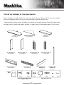 2
2
-
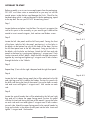 3
3
-
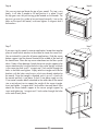 4
4
-
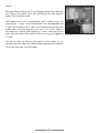 5
5
-
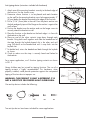 6
6
-
 7
7
-
 8
8
-
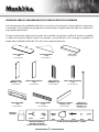 9
9
-
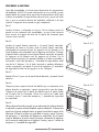 10
10
-
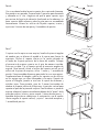 11
11
-
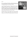 12
12
-
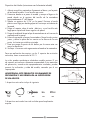 13
13
-
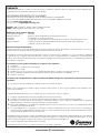 14
14
-
 15
15
-
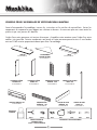 16
16
-
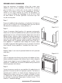 17
17
-
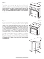 18
18
-
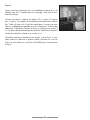 19
19
-
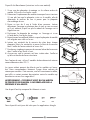 20
20
-
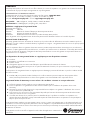 21
21


Muskoka MEF2803CCHB Assembly Instructions Manual
- Categoría
- Chimeneas
- Tipo
- Assembly Instructions Manual
En otros idiomas
- français: Muskoka MEF2803CCHB
- English: Muskoka MEF2803CCHB
Documentos relacionados
-
Muskoka MTVS4242SE Instrucciones de operación
-
-
-
-
-
-
-
Otros documentos
-
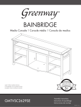 Greenway GMTVSC2629SE Guía del usuario
-
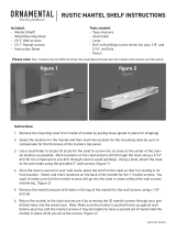 Ornamental Mouldings CLASSIC5WHW Guía de instalación
-
FMI W26LTF Manual de usuario
-
Runfine RFBE12301 Instrucciones de operación
-
Patio Festival PF18221 Instrucciones de operación
-
Ornamental Mouldings RUSTIC5WM Guía de instalación
-
Blackstone 1575 El manual del propietario
-
KitchenAid 790-0006A/0007A El manual del propietario
-
BBQ PG-CG004 El manual del propietario
-
 Kitchenaid - Old 810-0021 - Old El manual del propietario


